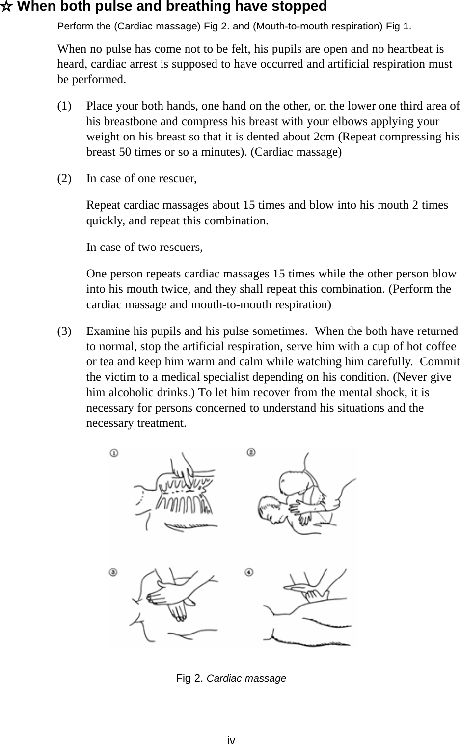
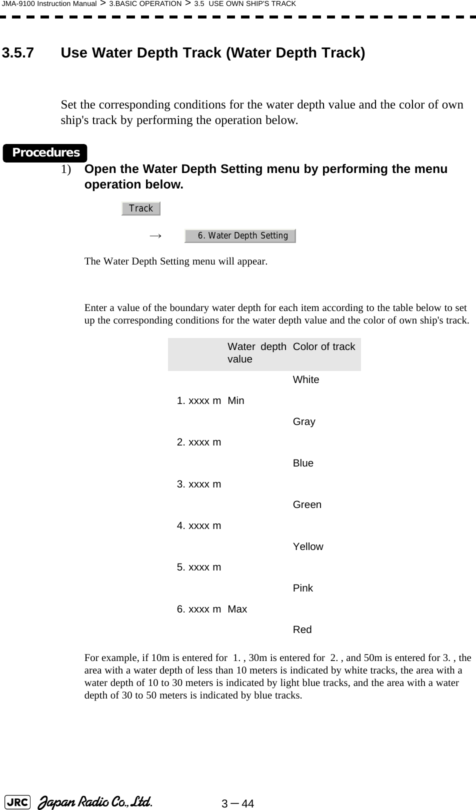
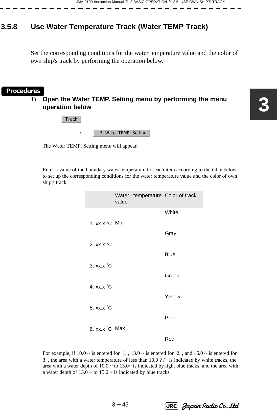
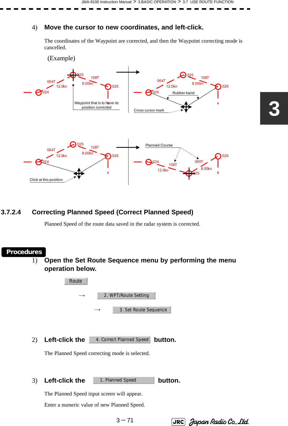
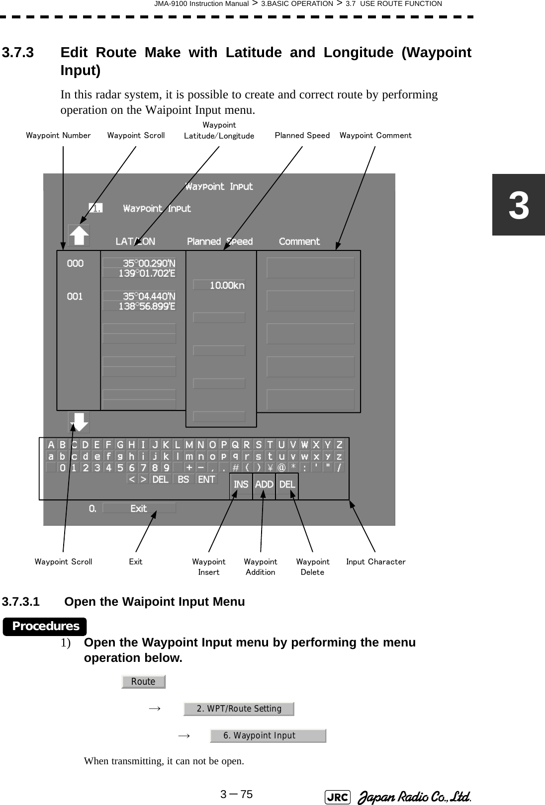
Japan Radio NKE1130 Marine Radar User Manual JMA 9100 series RADAR Instruction Manual
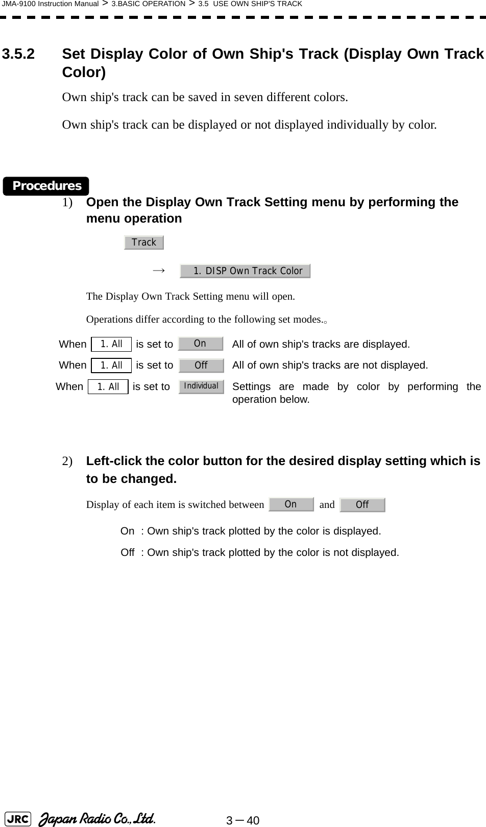
Japan Radio Co Ltd. Marine Radar JMA 9100 series RADAR Instruction Manual
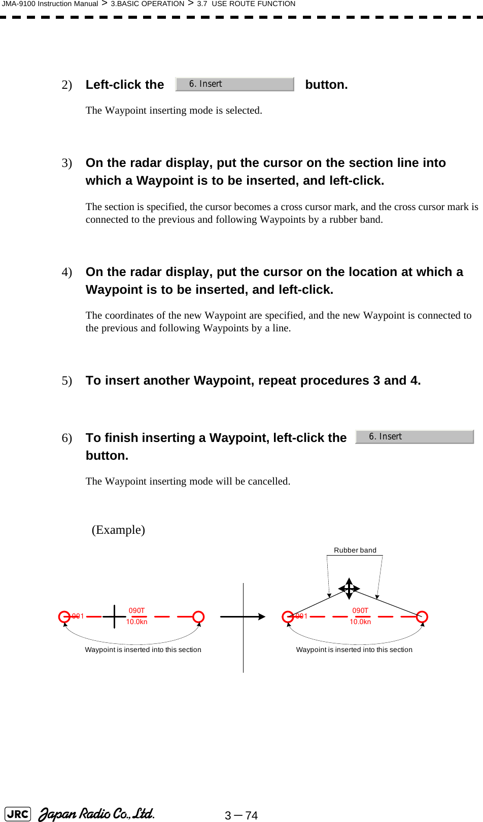
Contents
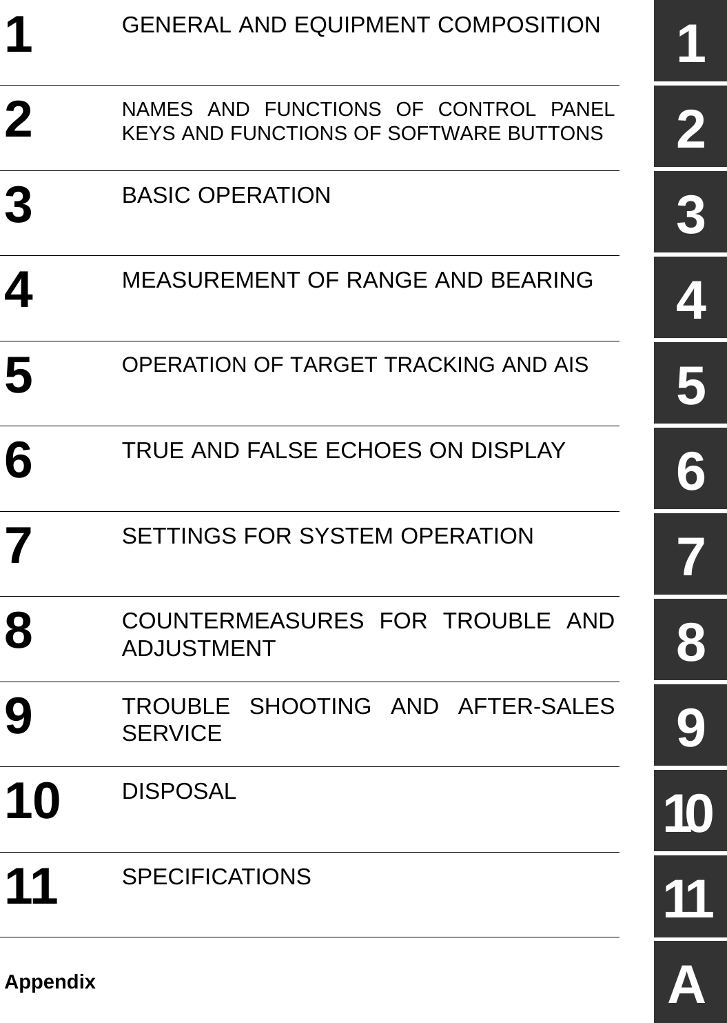
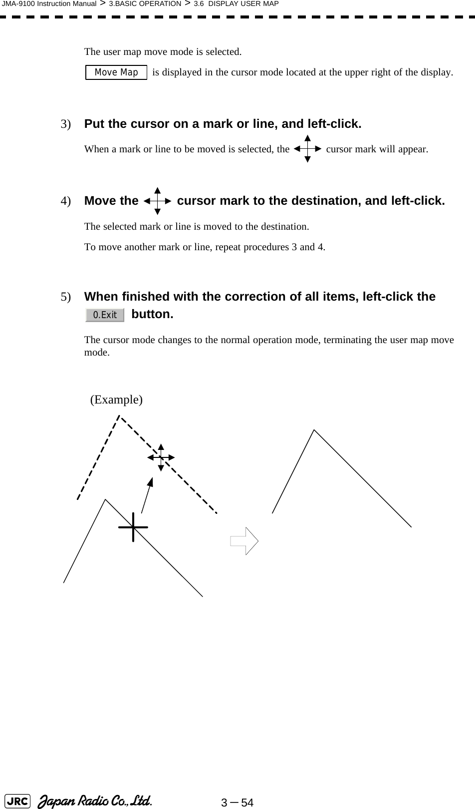
- 1. Users Manual 1
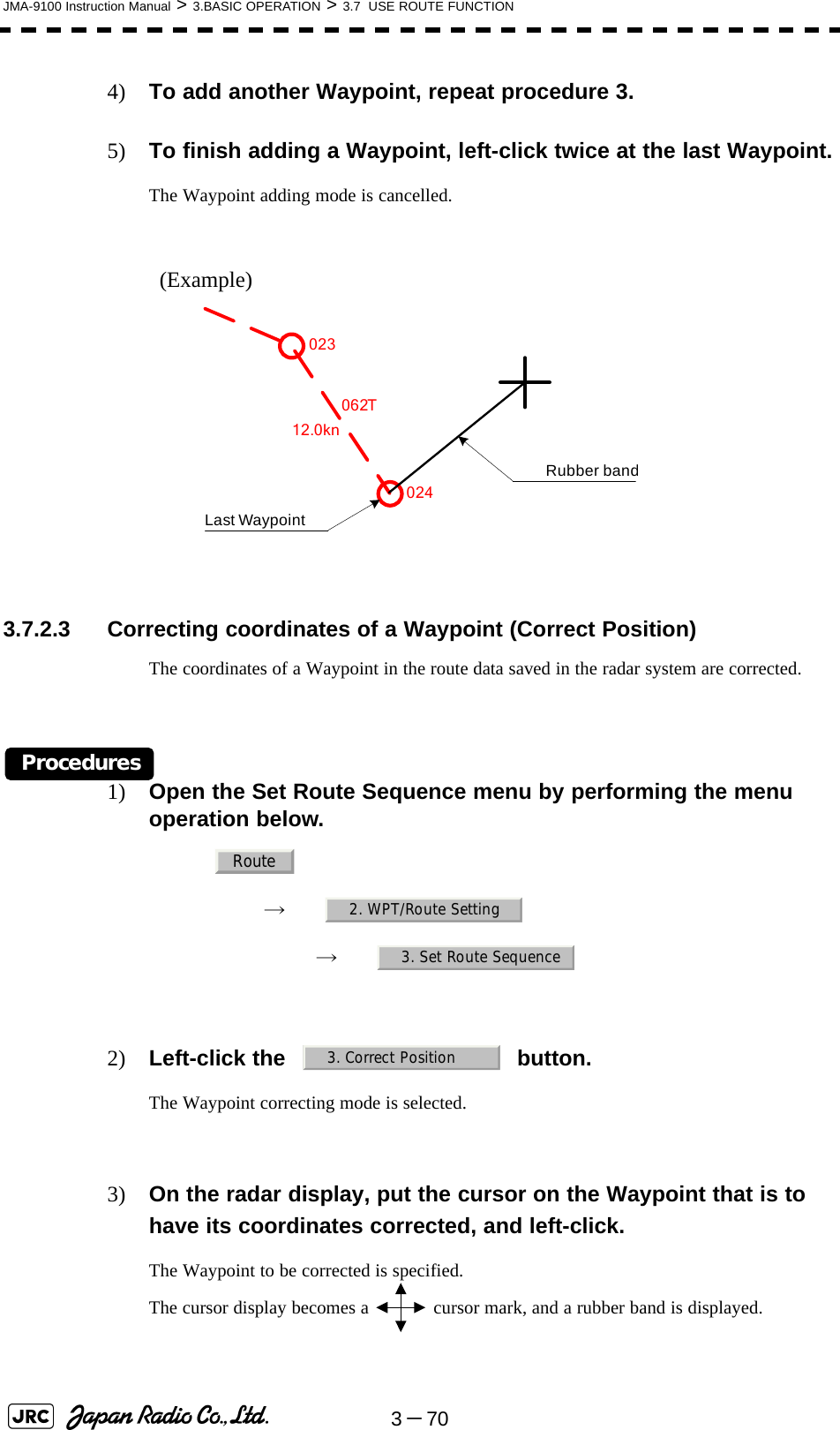
- 2. Users Manual 2
- 3. Users Manual 3
- 4. Users Manual
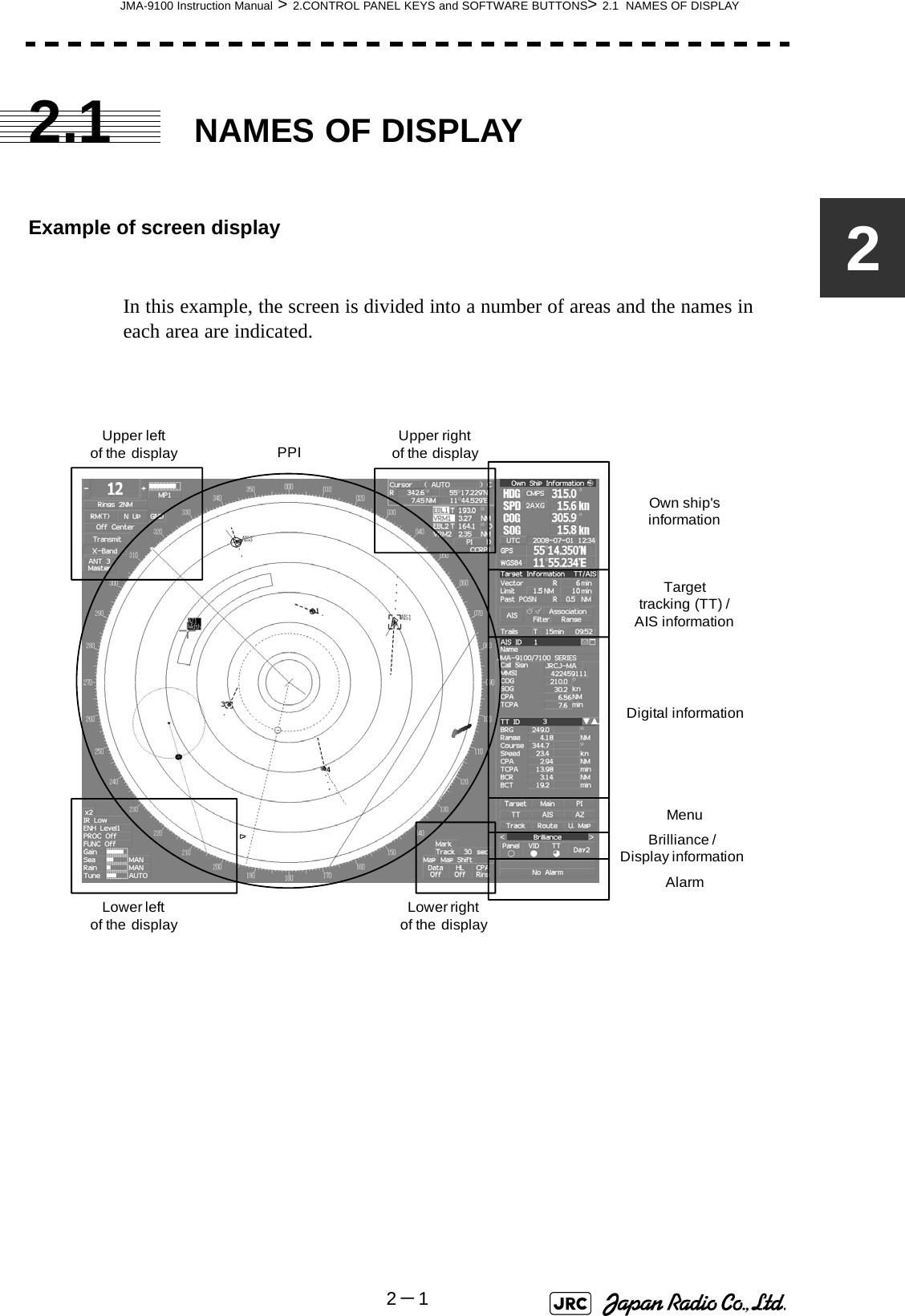
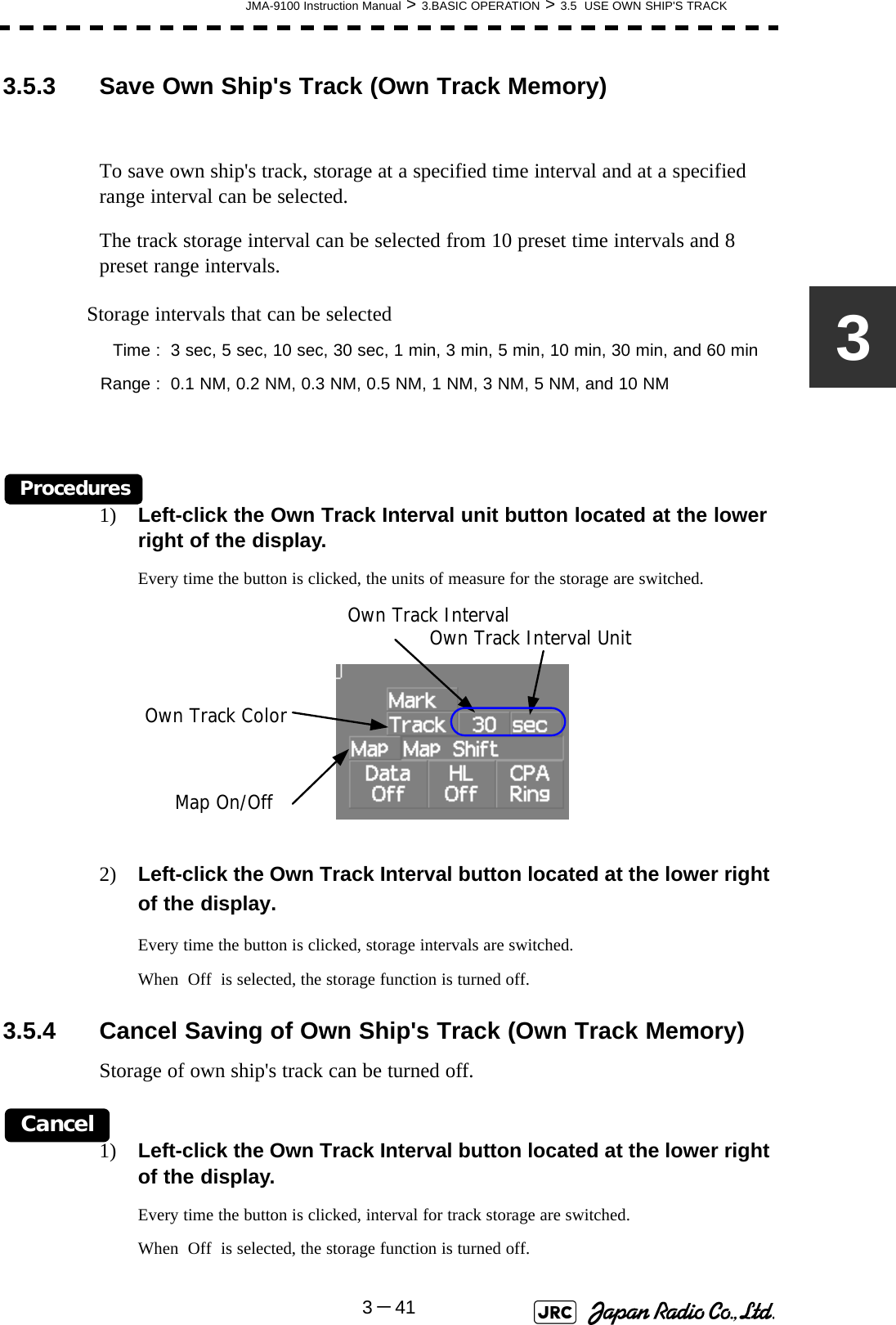
Users Manual 1
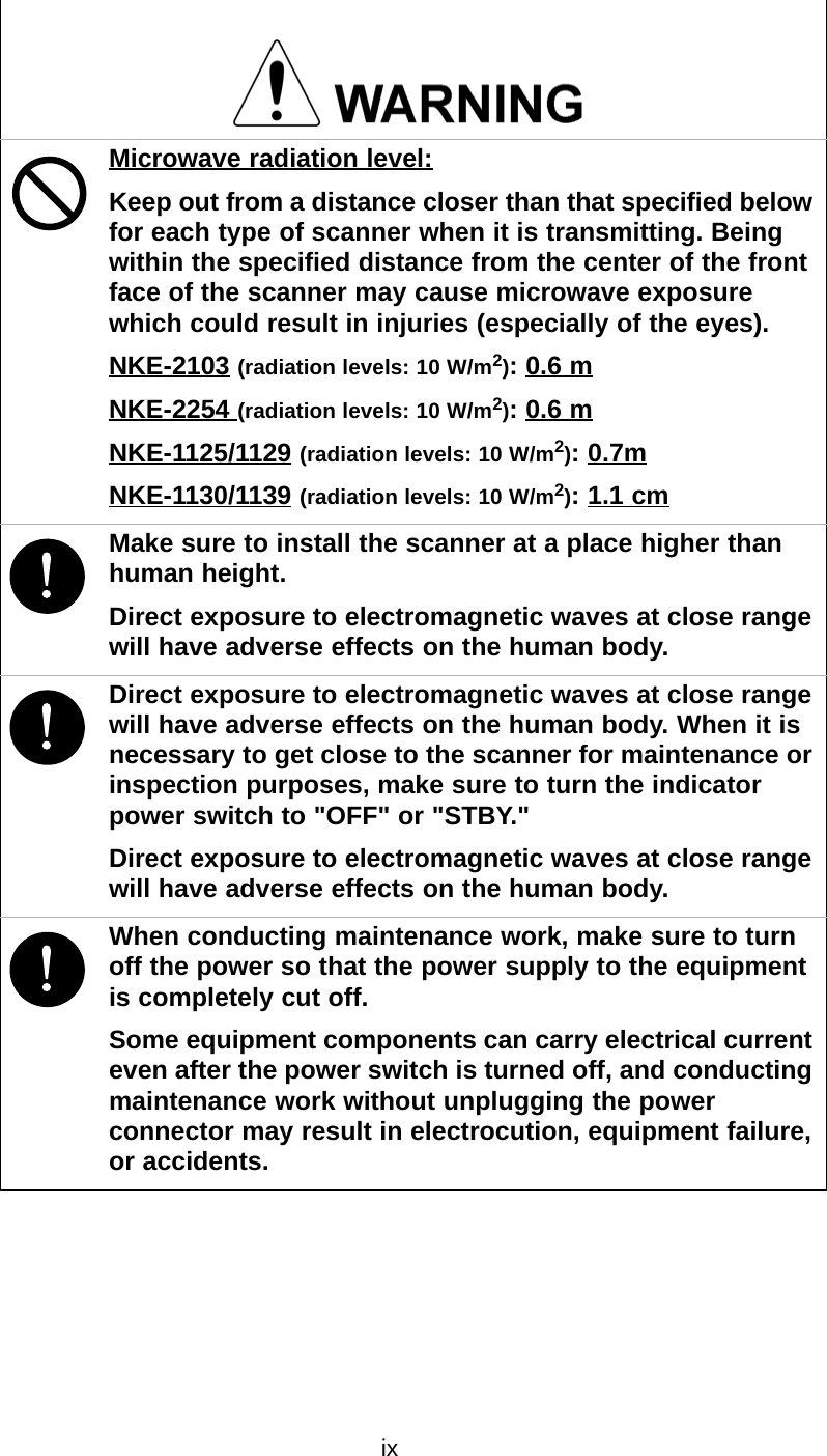
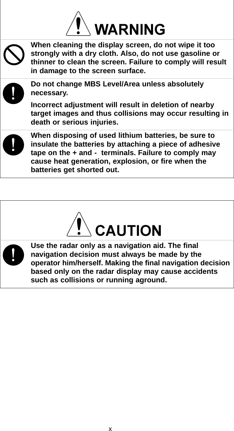
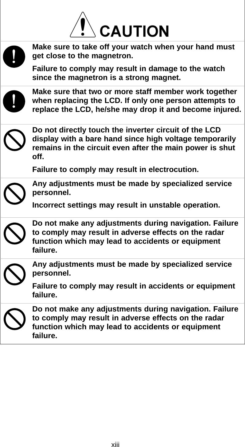
![xi!Use Target Tracking (TT) function only as a navigation aid. The final navigation decision must always be made by the operator him/herself. Making the final navigation decision based only on tracking target information may cause accidents.Tracking target information such as vector, target numerical data, and alarms may contain some errors. Also, targets that are not detected by the radar cannot be acquired or tracked.Making the final navigation decision based only on the radar display may cause accidents such as collisions or running aground.!A malfunction may occur if the power in the ship is instantaneously interrupted during operation of the radar. In this case, the power should be turned on again.When using the [AUTO SEA] function, never set the suppression level too high canceling out all image noises from the sea surface at close range.Detection of not only echoes from waves but also targets such as other ships or dangerous objects will become inhibited.When using the [AUTO SEA] function, make sure to choose the most appropriate image noise suppression level.When using the [AUTO RAIN] function, never set the suppression level too high canceling out all image noises from the rain or snow at close range.Detection of not only echoes from the rain or snow but also targets such as other ships or dangerous objects will become inhibited.When using the [AUTO RAIN] function, make sure to choose the most appropriate image noise suppression level.](https://usermanual.wiki/Japan-Radio/NKE1130.Users-Manual-1/User-Guide-994629-Page-13.png)

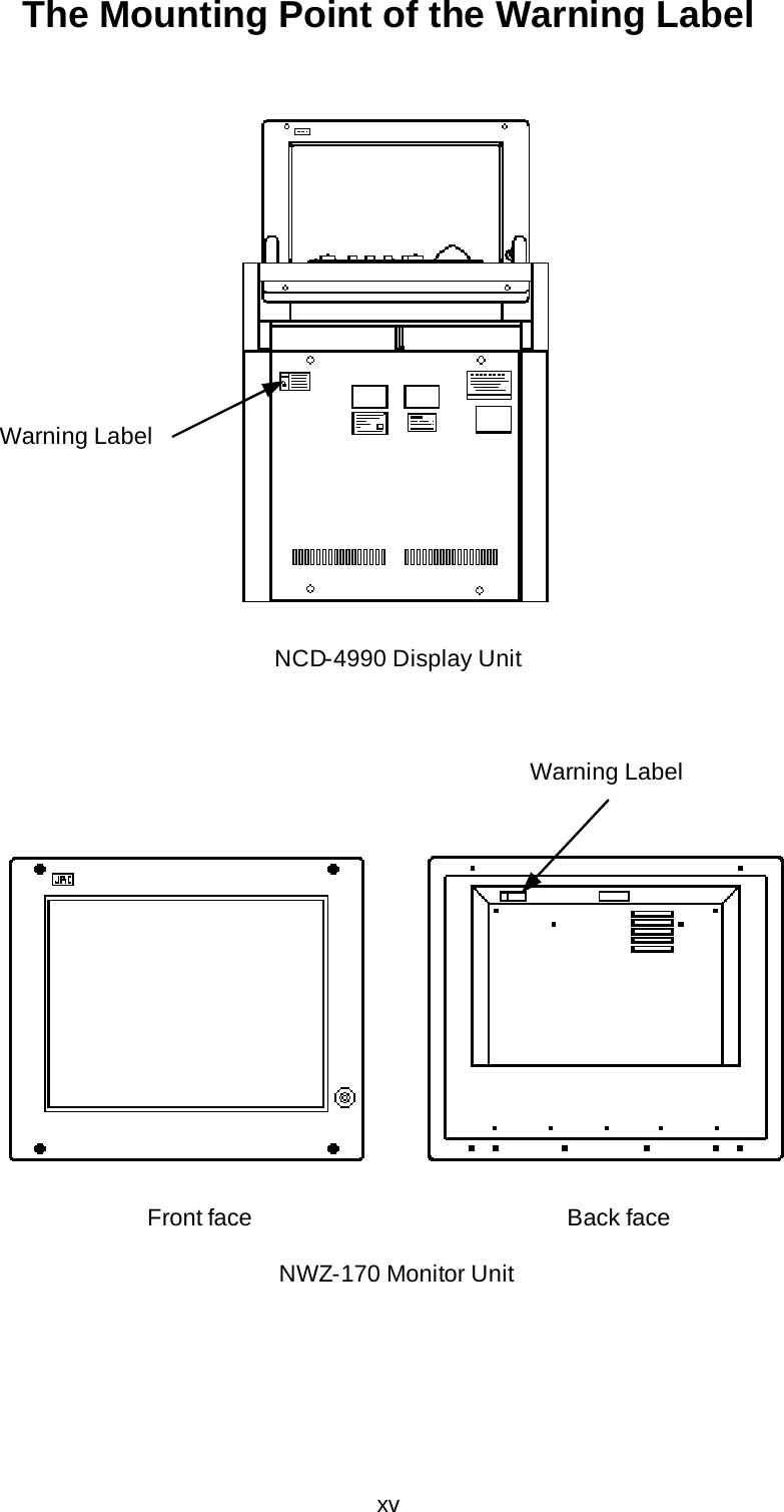
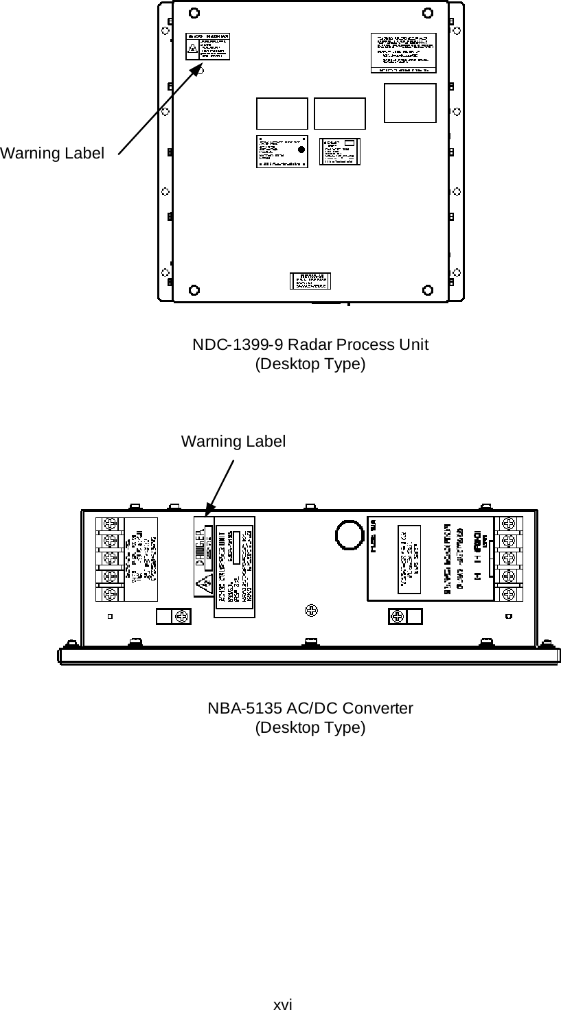
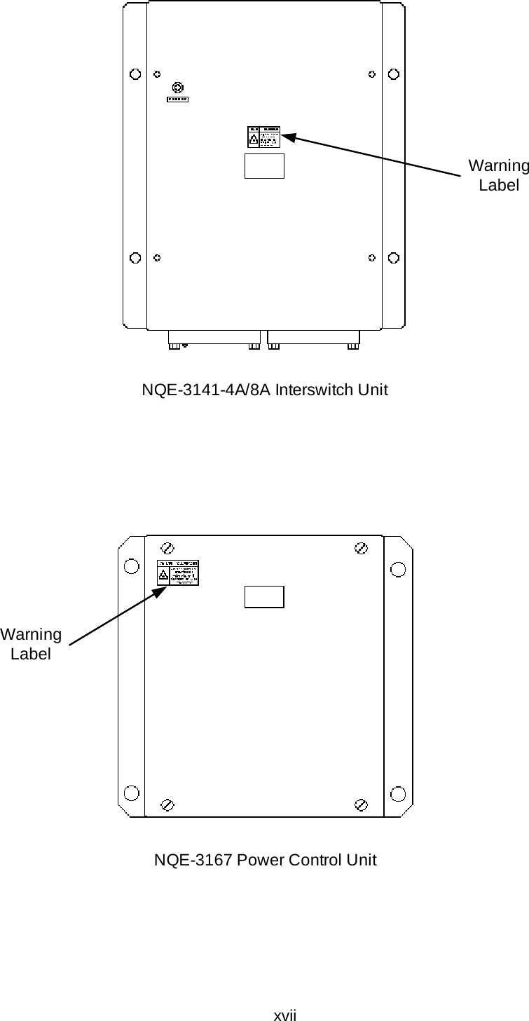
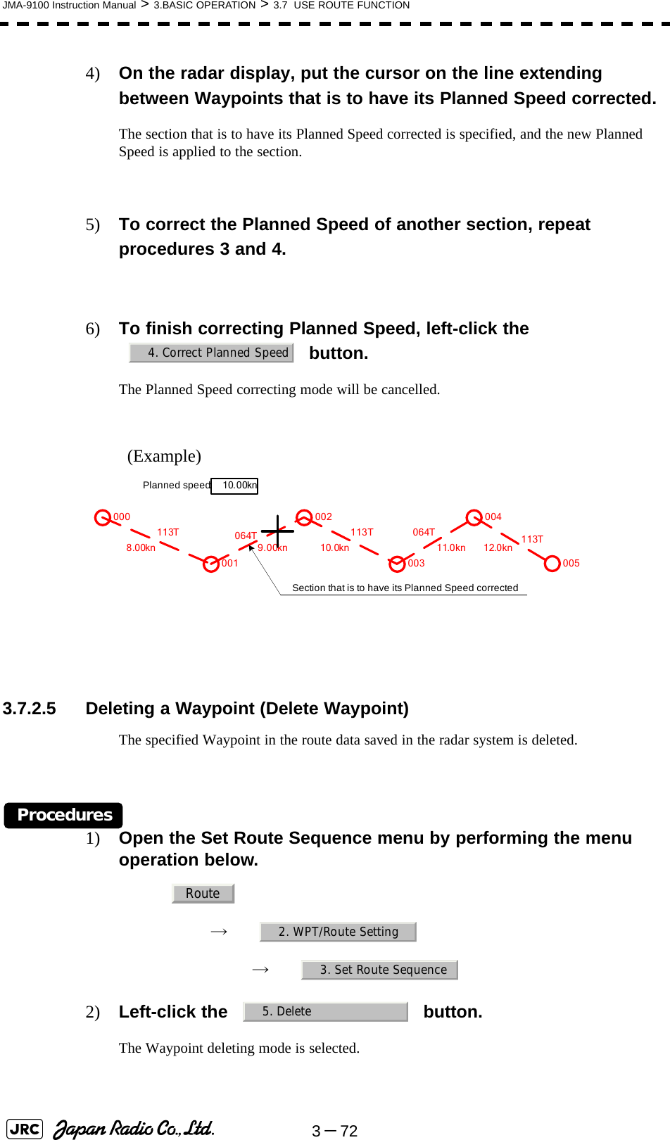
![Index◆◆◆ PRECAUTIONS BEFORE OPERATION ◆◆◆.............................................. i◆◆◆ FIRST-AID TREATMENTS ◆◆◆.................................................................. iiPREFACE ................................................................................................................... vThe Mounting Point of the Warning Label................................................................. xvEQUIPMENT APPEARANCE ................................................................................... xxGLOSSARY ............................................................................................................ xxviSECTION 1GENERAL AND EQUIPMENT COMPOSITION1.1 FUNCTIONS ...........................................................................................1-11.1.1 Function of This System .................................................................1-11.2 FEATURES .............................................................................................1-21.3 CONFIGURATION ..................................................................................1-41.4 EXTERIOR DRAWINGS .........................................................................1-61.5 GENERAL SYSTEM DIAGRAMS ........................................................1-26SECTION 2NAMES AND FUNCTIONS OF CONTROL PANEL KEYS AND FUNCTIONS OF SOFTWARE BUTTONS2.1 NAMES OF DISPLAY .............................................................................2-12.2 NAMES AND FUNCTIONS OF CONTROL PANEL KEYS ..................2-112.3 FUNCTIONS OF SOFTWARE BUTTONS ...........................................2-16SECTION 3BASIC OPERATION3.1 OPERATION FLOW ...............................................................................3-13.1.1 Power ON and Start the System ....................................................3-23.1.2 Observe and Adjust Video ..............................................................3-43.1.3 Acquire and Measure Data .............................................................3-43.1.4 Display and Measure with Reference to CCRP ............................3-43.1.5 End the Operation and Stop the System .......................................3-53.2 OBSERVE AND ADJUST VIDEO ..........................................................3-63.2.1 Adjust Monitor Brilliance [BRILL] ..................................................3-63.2.2 Change Observation Range [RANGE+/-] ......................................3-63.2.3 Tune ..................................................................................................3-73.2.4 Adjust Gain [GAIN] .........................................................................3-83.2.5 Suppress Sea Clutter [SEA] ..........................................................3-93.2.6 Suppress Rain/Snow Clutter [RAIN] ...........................................3-11](https://usermanual.wiki/Japan-Radio/NKE1130.Users-Manual-1/User-Guide-994629-Page-33.png)
![3.2.7 Reset Alarm Buzzer [ALARM ACK] .............................................3-123.2.8 To get the appropriate image that targets can be easily observed ............3-133.3 OPERATION PROCEDURES ..............................................................3-143.3.1 Move Cross Cursor Mark by Trackball ........................................3-143.3.2 Operate Software Buttons ...........................................................3-153.3.3 Basic Menu Operation ..................................................................3-163.3.4 Operation on Numeric Value, Latitude / Longitude and Character Input menu .......3-173.3.5 Overview of Menu Structure .........................................................3-223.4 GENERAL RADAR OPERATION ........................................................3-233.4.1 Interference Rejection (IR) ............................................................3-233.4.2 Switch Transmitter Pulse Length [GAIN] ....................................3-243.4.3 Target Enhance (ENH) ..................................................................3-253.4.4 Use Video Processing (PROC) .....................................................3-263.4.5 Switch Azimuth Display Mode (AZI MODE) ................................3-273.4.6 Switch True/Relative Motion Display Mode (TM/RM) .................3-283.4.7 Move Own Ship’s Display Position (Off Center) .........................3-293.4.8 Display Radar Trails (Trails) .........................................................3-303.4.9 Zoom (x2) .......................................................................................3-333.4.10 Hide/Display Range Rings [HL OFF] ...........................................3-343.4.11 Hide Graphics Information on Radar Display [DATA OFF] .......3-343.4.12 Switch Day/Night Mode [DAY/NIGHT] .........................................3-353.4.13 Adjust Operation Panel Brilliance [PANEL] ................................3-353.4.14 Set True Bearing ............................................................................3-363.4.15 Set Own Ship Speed .....................................................................3-363.4.16 Magnet Compass Correction (MAG Compass Setting) .............3-373.5 USE OWN SHIP'S TRACK ...................................................................3-393.5.1 Display Own Ship’s Track (Display Own Track) .........................3-393.5.2 Set Display Color of Own Ship's Track (Display Own Track Color) ..3-403.5.3 Save Own Ship's Track (Own Track Memory) ............................3-413.5.4 Cancel Saving of Own Ship's Track (Own Track Memory) ........3-413.5.5 Clear Own Ship's Track (Clear Own Track) ................................3-423.5.6 Use Expanded Own Ship's Track (Own Track Type) .................3-423.5.7 Use Water Depth Track (Water Depth Track) ..............................3-443.5.8 Use Water Temperature Track (Water TEMP Track) ..................3-453.5.9 Use Tidal Current Track (Current Vector Track) .........................3-46](https://usermanual.wiki/Japan-Radio/NKE1130.Users-Manual-1/User-Guide-994629-Page-34.png)
![3.6 DISPLAY USER MAP ...........................................................................3-473.6.1 Create User Map (Mark/Line) ........................................................3-473.6.2 Set User Map Display (Mark Display Setting) .............................3-503.6.3 Edit User Map (Edit User Map) .....................................................3-523.6.4 Correct Position on User Map (Shift User Map) .........................3-603.6.5 Save User Map ...............................................................................3-613.6.6 Set and Display Geodetic System (Geodetic) .............................3-653.7 USE ROUTE FUNCTION ......................................................................3-673.7.1 Display Route/Destination Mark (Select Route) .........................3-673.7.2 Edit Route (Set Route Sequence) ................................................3-683.7.3 Edit Route Make with Latitude and Longitude (Waypoint Input) .......3-753.7.4 Use Route Monitoring Function (Waypoint/Route Alarm) .........3-793.7.5 Method of Using Route .................................................................3-813.7.6 Detailed Route Settings ................................................................3-823.7.7 Clear Waypoint/Route Data (Clear WPT/Route Data) .................3-863.7.8 Operate Route Data File ................................................................3-873.8 APPLIED OPERATIONS ......................................................................3-913.8.1 Set Radar Signal Processing (Process Setting) .........................3-913.8.2 Set Radar Trails (RADAR Trails Setting) .....................................3-953.8.3 Set Scanner Unit (TXRX Setting) .................................................3-973.8.4 Set Cursor (Cursor Setting) ..........................................................3-983.8.5 Set Radar Display (Display Setting) ............................................3-993.8.6 Adjust Sound Volume (Buzzer Volume) ....................................3-1023.8.7 Set User Option Keys [OPTION 1/2] ..........................................3-1033.8.8 Set Navigation Data Display (Multi Window Setting) ...............3-1053.8.9 AUTO Backup ..............................................................................3-1103.9 USE FUNCTION KEY [USER] ...........................................................3-1113.9.1 Operation Procedures .................................................................3-1113.9.2 Function Setting Menu Items .....................................................3-1123.9.3 Overview of Function Operations (User Function Setting) .....3-1133.9.4 Overview of saved Function Setting Data .................................3-1173.10 USE USER SETTING .........................................................................3-1183.10.1 Save Operating State (Save User Setting) ................................3-1183.10.2 Load Operating State (Load User Setting) ................................3-1193.10.3 Delete Operating State (Delete User Setting) ...........................3-119](https://usermanual.wiki/Japan-Radio/NKE1130.Users-Manual-1/User-Guide-994629-Page-35.png)
![3.11 USING CARD .....................................................................................3-1203.11.1 Operate File on the Card (File Manager) ...................................3-120SECTION 4MEASUREMENT OF RANGE AND BEARING4.1 USE OF NAVIGATION TOOLS ..............................................................4-14.1.1 Using Cursor (Cursor) ....................................................................4-24.1.2 Using Range Rings (Range Rings) ................................................4-24.1.3 Using Electronic Bearing Line (EBL1/EBL2) ................................4-34.1.4 Using Parallel Index Lines (PI Menu) .............................................4-84.1.5 Operating EBL Maneuver Function (EBL Maneuver Setting) ....4-144.1.6 Operating EBL, VRM, and PI with Cursor ...................................4-164.2 MEASUREMENT OF RANGE AND BEARING ....................................4-194.2.1 Measurement with Cursor Position (Cursor) ..............................4-194.2.2 Measurement with Electronic Bearing Line and Variable Range Marker [EBL] [VRM] .......................................................................................4-204.2.3 Measurement with Two Arbitrary Points .....................................4-21SECTION 5OPERATION OF TARGET TRACKING AND AIS5.1 PREPARATION ......................................................................................5-15.1.1 Collision Avoidance ........................................................................5-25.1.2 Definitions of Symbols ...................................................................5-55.1.3 Radar Display ..................................................................................5-85.1.4 Cursor Modes (Cursor) .................................................................5-105.1.5 Setting Collision Decision Criteria ..............................................5-125.1.6 Setting Vectors (Vector Time) ......................................................5-135.1.7 Setting the GPS antenna location ................................................5-135.2 TARGET TRACKING OPERATION .....................................................5-145.2.1 Acquiring Target [ACQ] ................................................................5-145.2.2 Canceling Unwanted Tracked Targets [ACQ CANCEL] .............5-165.2.3 Tracked Target Data Display [TGT DATA] ..................................5-175.2.4 Displaying Target ID No.(Target Number Display) .....................5-185.2.5 Adding Tracked Target ID Name (Name) .....................................5-195.2.6 Reference Target (Reference) ......................................................5-205.2.7 Operation Test (TT Test Menu) ...................................................5-21](https://usermanual.wiki/Japan-Radio/NKE1130.Users-Manual-1/User-Guide-994629-Page-36.png)
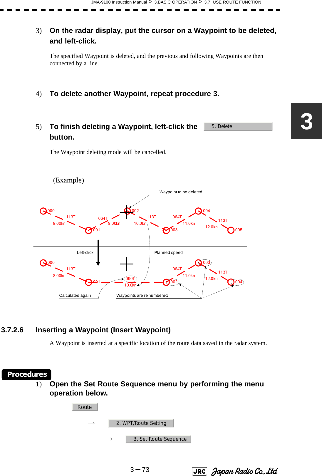
![5.3 AIS OPERATION ..................................................................................5-265.3.1 Restrictions ....................................................................................5-265.3.2 Setting AIS Display Function (AIS Function) ..............................5-265.3.3 Activate AIS Targets (Activate AIS) .............................................5-275.3.4 Deactivate AIS Targets (Deactivate AIS) .....................................5-275.3.5 Displaying AIS Information [TGT DATA] .....................................5-285.3.6 Displaying Target ID No. (Target Number Display) ....................5-315.3.7 Setting AIS Filter (AIS Filter Setting) ...........................................5-325.3.8 Conditions for Deciding AIS Target to be Lost ..........................5-355.3.9 Setting Conditions for AIS Alarm (AIS Alarm Setting) ...............5-365.4 DECISION OF TARGETS AS IDENTICAL (Association) ...................5-375.4.1 Setting of Function to Decide Targets as Identical (Association) .....5-375.4.2 Setting of Conditions for Deciding AIS and Tracked Targets as Identical (Association Setting) .............................................................................5-375.4.3 Types of Decision Conditions to be Set ......................................5-385.5 ALARM DISPLAY .................................................................................5-395.5.1 CPA / TCPA Alarm .........................................................................5-405.5.2 Alarm for New Target Acquired in Automatic Acquisition Zone (New Target) ..............................................................................................5-415.5.3 Lost Target Alarm (Lost) ...............................................................5-415.5.4 Gyro Set Alarm ..............................................................................5-425.6 TRACK FUNCTION ..............................................................................5-435.6.1 Past Position (Past POSN) ...........................................................5-435.6.2 Target Ship's Tracks (Target Track) ............................................5-445.7 TRIAL MANEUVERING (Trial Maneuver) ..........................5-535.7.1 Trial Maneuvering in the True Vector Mode ................................5-545.7.2 Trial Maneuvering in the Relative Vector Mode ..........................5-555.7.3 Operation of Trial Maneuvering Function ...................................5-56SECTION 6TRUE AND FALSE ECHOES ON DISPLAY6.1 RADAR WAVE WITH THE HORIZON ...................................................6-16.2 STRENGTH OF REFLECTION FROM THE TARGET ...........................6-36.3 SEA CLUTTER AND RAIN AND SNOW CLUTTER ..............................6-56.4 FALSE ECHOES ....................................................................................6-96.5 DISPLAY OF RADAR TRANSPONDER (SART) ................................6-12](https://usermanual.wiki/Japan-Radio/NKE1130.Users-Manual-1/User-Guide-994629-Page-37.png)


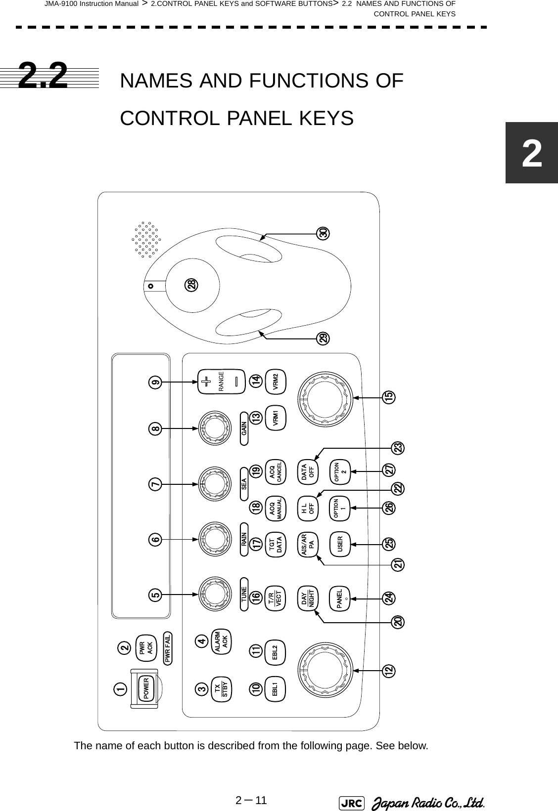
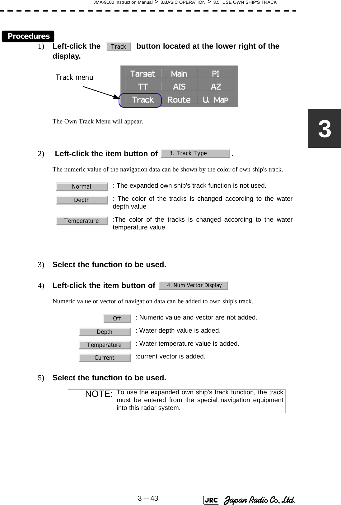
![2-12JMA-9100 Instruction Manual > 2.CONTROL PANEL KEYS and SOFTWARE BUTTONS > 2.2 NAMES AND FUNCTIONS OF CONTROL PANEL KEYS [POWER] (Power supply) switchThe lamp is lit and the equipment is activated.If this switch is pressed while the equipment is running, the power of the equipment is shut down.→3.1.1 on page 3-2 [PWR ACK] (Power alarm acknowledgement) keyUse this function to acknowledge the alarm when power supply abnormality occurs.To enable this key, an external battery (separate power from normal AC) is required. [TX/STBY] (Transmission/Standby) keyWhen the [POWER] switch is pressed, the "STANDBY" message is displayed in the top-left corner of the screen in about 3 minutes. If this key is pressed, transmission starts. If this key is pressed during transmission, the equipment is set to a standby state.→3.1.1 on page 3-2 [ALARM ACK] (Alarm acknowledgement) keyUse this function to acknowledge alarms such as failure alarm, approaching target alarm, and collision alarm.By pressing this key at the occurrence of an alarm, the alarm sound can be stopped.If multiple alarms occur, press this key same time as the alarms.→3.2.7 on page 3-12 [TUNE] (Tuning) dialUse his function to tune a transmitter.The mode is switched to manual/automatic whenever this dial is pressed.→3.2.3 on page 3-7 [RAIN] (Rain / snow clutter suppression) dialThis function suppresses rain / snow clutters.To increase the effect of suppression, turn the dial clockwise.The mode can be switched to manual or automatic by pressing the dial.→3.2.6 on page 3-11 [SEA] (Sea clutter suppression) dialThis function suppresses sea clutter.To increase the effect of suppression, turn the dial clockwise.The mode can be switched to manual or automatic by pressing the dial.→3.2.5 on page 3-91234567](https://usermanual.wiki/Japan-Radio/NKE1130.Users-Manual-1/User-Guide-994629-Page-96.png)
![JMA-9100 Instruction Manual > 2.CONTROL PANEL KEYS and SOFTWARE BUTTONS> 2.2 NAMES AND FUNCTIONS OFCONTROL PANEL KEYS2-132 [GAIN] (Gain/pulse length) dialThis function adjusts the reception sensitivity of the radar.To increase the sensitivity, turn the dial clockwise.The transmission pulse width can be switched by pressing the dial.gain→3.2.4 on page 3-8pulse width→3.4.2 on page 3-24 [RANGE +/-] (Range switching) keyThis function switches the range.Press [+] to increase the observation range.Press [-] to reduce the observation range.→3.2.2 on page 3-6 [EBL1] (Electronic Bearing Line 1) keyUse this function to display and select EBL1.If the key is pressed for 2 seconds or more, the menu for setting EBL1 is displayed.→4.1.3 on page 4-3 [EBL2] (Electronic Bearing Line 2) keyUse this function to display and select EBL2.If the key is pressed for 2 seconds or more, the menu for setting EBL2 is displayed.→4.1.3 on page 4-3 [EBL] (Electronic Bearing Line) dialThis function rotates the azimuth of the EBL that is selected in EBL1/2.By pressing the dial, the selected EBL can be switched to Center fixing → Floating → Center fixing.→4.1.3 on page 4-3 [VRM1] (Variable Range Marker 1) keyThis function selects VRM1. The On/Off and dial use right are switched.→ on page 4-6 [VRM2] (Variable Range Marker 2) keyThis function selects VRM2. The On/Off and dial use right are switched.→ on page 4-6891011121314](https://usermanual.wiki/Japan-Radio/NKE1130.Users-Manual-1/User-Guide-994629-Page-97.png)
![2-14JMA-9100 Instruction Manual > 2.CONTROL PANEL KEYS and SOFTWARE BUTTONS > 2.2 NAMES AND FUNCTIONS OF CONTROL PANEL KEYS [VRM] (Variable Range Marker) dialThis function changes the range of the VRM that is selected by VRM1/2.By pressing the dial, the parallel line cursor function can be switched to Operation → Fixed → Off → Operation.→ on page 4-6 [T/R VECT] (True vector display / Relative vector display) keyThis function switches the display mode (true/relative) of the tracked target and AIS target vector.→5.1.6 on page 5-13 [TGT DATA] (Target data display) keyThis function displays the digital data of the tracked target or AIS target at the cursor position.the tracked target→5.2.3 on page 5-17the AIS target→5.3.5 on page 5-28 [ACQ MANUAL] (Manual acquisition) keyThis function enables manual acquisition of the target at the cursor position.→5.2.1 on page 5-14 [ACQ CANCEL] (Tracked target cancellation) keyThis function cancels the symbol and vector of the target that is being tracked and stops the tracking of the target.If this key is pressed for 2 seconds or more, all the targets that are being tracked are cancelled.→5.2.2 on page 5-16 [DAY/NIGHT] (Day/night mode) keyThis function switches the color and brightness of the screen that was preset.→3.4.12 on page 3-35 [AIS/TT] (AIS On/Off) keyThis function switches the AIS function to ON/OFF when the AIS function is enabled.→5.3.2 on page 5-26 [HL OFF] (Ship's heading line Off) keyHL (ship's heading highlight line) can be set to Off only while this key is pressed.→3.4.10 on page 3-341516171819202122](https://usermanual.wiki/Japan-Radio/NKE1130.Users-Manual-1/User-Guide-994629-Page-98.png)
![JMA-9100 Instruction Manual > 2.CONTROL PANEL KEYS and SOFTWARE BUTTONS> 2.2 NAMES AND FUNCTIONS OFCONTROL PANEL KEYS2-152 [DATA OFF] (DATA Off) keyThis function sets the graphics other than HL, range ring, EBL, and VRM to OFF temporarily while this key is pressed.→3.4.11 on page 3-34 [PANEL] (Operator panel brilliance) keyThis function adjusts the lighting brilliance of various switches and dial positions on the operator panel. The brightness changes cyclically whenever this key is pressed.→3.4.13 on page 3-35 [USER] keyBy pressing this key, the signal processing setting that is preset can be called.The setting changes to FUNC OFF ==> FUNC1 ==> FUNC2 ==> FUNC3 ==> FUNC4 whenever this key is pressed.If this key pressed for 2 seconds or more, the function setting menu is displayed.→3.9 on page 3-111 [OPTION1] keyBy pressing this key, the pre-registered menu position can be directly displayed. At factory shipment, the calling of [Main Menu] is assigned.→3.8.7 on page 3-103 [OPTION2] keyBy pressing this key, the pre-registered menu position can be directly displayed. At factory shipment, the calling of [Sub Menu] is assigned.→3.8.7 on page 3-103 Track ballThis function moves the cursor mark to any position. Use this function for setting in each mode.Use this function to specify a center position of floating EBL and an off-center position.→3.3.1 on page 3-14 [Track ball left button] Use this function to confirm menu selection and numeric value input. [Track ball right button] Use this function to reset menu selection and numeric value input. [BRILL] (Brilliance dial)This dial is provided at the right of the monitor. Use this function to adjust the brilliance of the monitor.→3.2.1 on page 3-6232425262728293031](https://usermanual.wiki/Japan-Radio/NKE1130.Users-Manual-1/User-Guide-994629-Page-99.png)

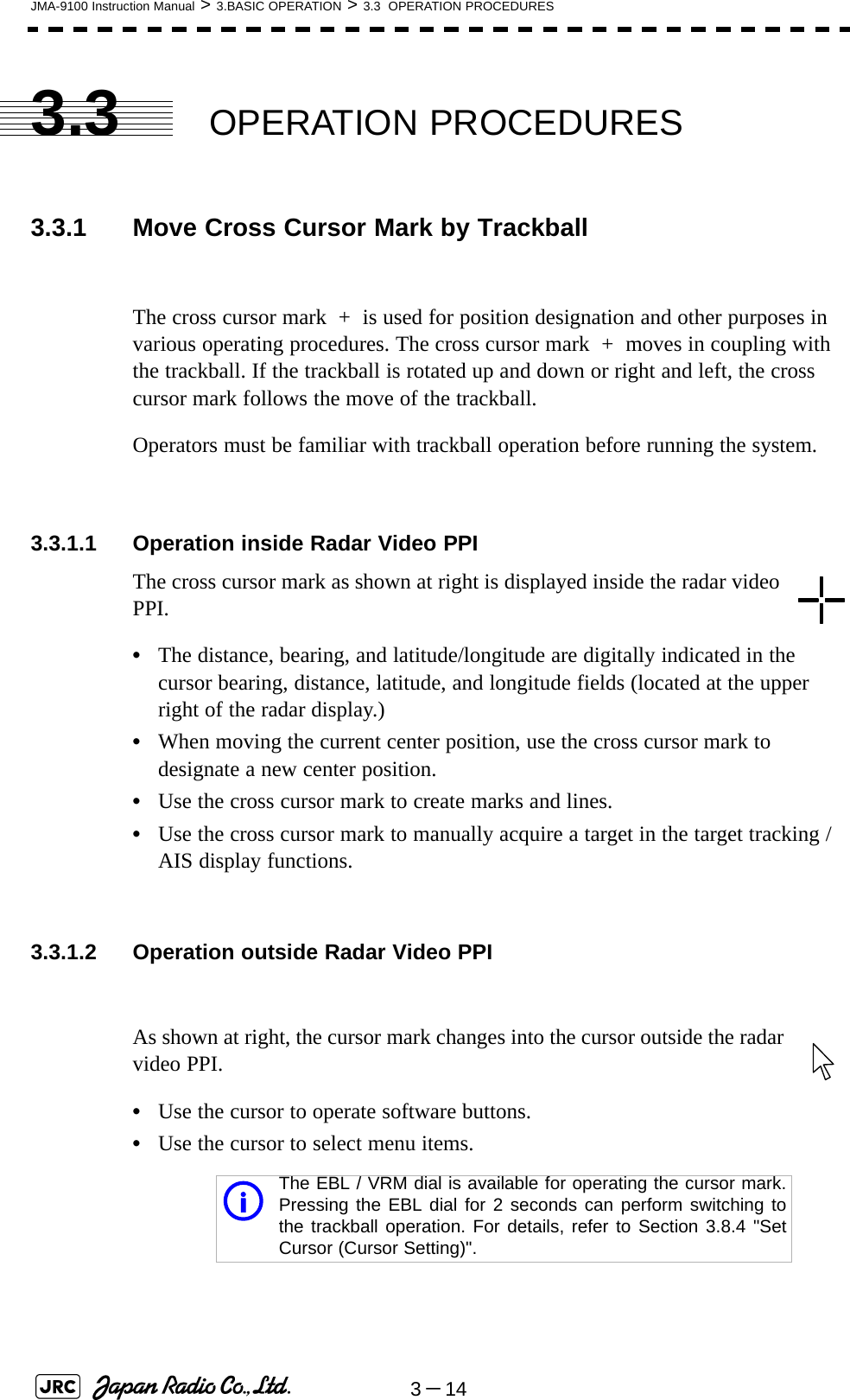
![BASIC OPERATION3.1 OPERATION FLOW ...............................................................................3-13.1.1 Power ON and Start the System ....................................................3-23.1.2 Observe and Adjust Video ..............................................................3-43.1.3 Acquire and Measure Data .............................................................3-43.1.4 Display and Measure with Reference to CCRP ............................3-43.1.5 End the Operation and Stop the System .......................................3-53.2 OBSERVE AND ADJUST VIDEO ..........................................................3-63.2.1 Adjust Monitor Brilliance [BRILL] ..................................................3-63.2.2 Change Observation Range [RANGE+/-] ......................................3-63.2.3 Tune ..................................................................................................3-73.2.4 Adjust Gain [GAIN] .........................................................................3-83.2.5 Suppress Sea Clutter [SEA] ..........................................................3-93.2.6 Suppress Rain/Snow Clutter [RAIN] ...........................................3-113.2.7 Reset Alarm Buzzer [ALARM ACK] .............................................3-123.2.8 To get the appropriate image that targets can be easily observed ...3-133.3 OPERATION PROCEDURES ..............................................................3-143.3.1 Move Cross Cursor Mark by Trackball ........................................3-14SECTION 3BASIC OPERATION](https://usermanual.wiki/Japan-Radio/NKE1130.Users-Manual-1/User-Guide-994629-Page-117.png)
![3.3.2 Operate Software Buttons ...........................................................3-153.3.3 Basic Menu Operation ..................................................................3-163.3.4 Operation on Numeric Value, Latitude / Longitude and Character Input menu .....................................................................................3-173.3.5 Overview of Menu Structure .........................................................3-223.4 GENERAL RADAR OPERATION ........................................................3-233.4.1 Interference Rejection (IR) ............................................................3-233.4.2 Switch Transmitter Pulse Length [GAIN] ....................................3-243.4.3 Target Enhance (ENH) ..................................................................3-253.4.4 Use Video Processing (PROC) .....................................................3-263.4.5 Switch Azimuth Display Mode (AZI MODE) ................................3-273.4.6 Switch True/Relative Motion Display Mode (TM/RM) .................3-283.4.7 Move Own Ship’s Display Position (Off Center) .........................3-293.4.8 Display Radar Trails (Trails) .........................................................3-303.4.9 Zoom (x2) .......................................................................................3-333.4.10 Hide/Display Range Rings [HL OFF] ...........................................3-343.4.11 Hide Graphics Information on Radar Display [DATA OFF] .......3-343.4.12 Switch Day/Night Mode [DAY/NIGHT] .........................................3-353.4.13 Adjust Operation Panel Brilliance [PANEL] ................................3-353.4.14 Set True Bearing ............................................................................3-363.4.15 Set Own Ship Speed .....................................................................3-363.4.16 Magnet Compass Correction (MAG Compass Setting) .............3-373.5 USE OWN SHIP'S TRACK ...................................................................3-393.5.1 Display Own Ship’s Track (Display Own Track) ......................3-393.5.2 Set Display Color of Own Ship's Track (Display Own Track Color) ..3-403.5.3 Save Own Ship's Track (Own Track Memory) ............................3-413.5.4 Cancel Saving of Own Ship's Track (Own Track Memory) ........3-413.5.5 Clear Own Ship's Track (Clear Own Track) ................................3-423.5.6 Use Expanded Own Ship's Track (Own Track Type) .................3-423.5.7 Use Water Depth Track (Water Depth Track) ..............................3-443.5.8 Use Water Temperature Track (Water TEMP Track) ..................3-453.5.9 Use Tidal Current Track (Current Vector Track) .........................3-463.6 DISPLAY USER MAP ...........................................................................3-473.6.1 Create User Map (Mark/Line) ........................................................3-473.6.2 Set User Map Display (Mark Display Setting) .............................3-503.6.3 Edit User Map (Edit User Map) .....................................................3-523.6.4 Correct Position on User Map (Shift User Map) .........................3-603.6.5 Save User Map ...............................................................................3-613.6.6 Set and Display Geodetic System (Geodetic) .............................3-653.7 USE ROUTE FUNCTION ......................................................................3-673.7.1 Display Route/Destination Mark (Select Route) .........................3-673.7.2 Edit Route (Set Route Sequence) ................................................3-683.7.3 Edit Route Make with Latitude and Longitude (Waypoint Input) .......3-753.7.4 Use Route Monitoring Function (Waypoint/Route Alarm) .........3-79](https://usermanual.wiki/Japan-Radio/NKE1130.Users-Manual-1/User-Guide-994629-Page-118.png)
![3.7.5 Method of Using Route .................................................................3-813.7.6 Detailed Route Settings ................................................................3-823.7.7 Clear Waypoint/Route Data (Clear WPT/Route Data) .................3-863.7.8 Operate Route Data File ................................................................3-873.8 APPLIED OPERATIONS ......................................................................3-913.8.1 Set Radar Signal Processing (Process Setting) .........................3-913.8.2 Set Radar Trails (RADAR Trails Setting) .....................................3-953.8.3 Set Scanner Unit (TXRX Setting) .................................................3-973.8.4 Set Cursor (Cursor Setting) ..........................................................3-983.8.5 Set Radar Display (Display Setting) ............................................3-993.8.6 Adjust Sound Volume (Buzzer Volume) ....................................3-1023.8.7 Set User Option Keys [OPTION 1/2] ..........................................3-1033.8.8 Set Navigation Data Display (Multi Window Setting) ...............3-1053.8.9 AUTO Backup ..............................................................................3-1103.9 USE FUNCTION KEY [USER] ...........................................................3-1113.9.1 Operation Procedures .................................................................3-1113.9.2 Function Setting Menu Items .....................................................3-1123.9.3 Overview of Function Operations (User Function Setting) .....3-1133.9.4 Overview of saved Function Setting Data .................................3-1173.10 USE USER SETTING .........................................................................3-1183.10.1 Save Operating State (Save User Setting) ................................3-1183.10.2 Load Operating State (Load User Setting) ................................3-1193.10.3 Delete Operating State (Delete User Setting) ...........................3-1193.11 USING CARD .....................................................................................3-1203.11.1 Operate File on the Card (File Manager) ...................................3-120](https://usermanual.wiki/Japan-Radio/NKE1130.Users-Manual-1/User-Guide-994629-Page-119.png)
![JMA-9100 Instruction Manual > 3.BASIC OPERATION > 3.1 OPERATION FLOW3-33Procedures1) Check that the ship’s mains are turned on.2) Press [POWER] key.The system is turned on, and the preheating time is displayed. is indicated at the upper left of the radar display.3) Wait until the preheating time is over.When the preheating time is over, the preheating time screen disappears, and at the upper left of the radar display changes to .4) Press [TX/STBY] key.The radar will start transmission and the antenna will start rotating. at the upper left of the radar display changes to .NOTE: The radar does not start transmission if you press [TX/STBY] key while is indicated.PreheatPreheatStandbyStandby TransmitPreheat](https://usermanual.wiki/Japan-Radio/NKE1130.Users-Manual-1/User-Guide-994629-Page-123.png)
![3-4JMA-9100 Instruction Manual > 3.BASIC OPERATION > 3.1 OPERATION FLOW3.1.2 Observe and Adjust VideoProcedures1) Press [RANGE+] key or [RANGE-] key to set the range to the scale required for target observation.2) [GAIN] [SEA] and [RAIN] to obtain the clearest targets.For how to adjust video, see Section 3.2 "OBSERVE AND ADJUST VIDEO" 3.1.3 Acquire and Measure DataFor details on how to acquire data and measure, see the SECTION 4"MEASUREMENT OF RANGE AND BEARING".3.1.4 Display and Measure with Reference to CCRPThe radar video, range, bearing, Target Tracking and AIS data display etc... are displayed with reference to CCRP (Consistent Common Reference Point).If scanner is switched, these data are measured from CCRP.If some kind of functions set scanner position to outside of the PPI range, these data except Target Tracking and AIS data are displayed with reference to scanner position.For how to setting CCRP, see the Section 7.1.9 "Setting of CCRP (CCRP Setting)". Refer to [GAIN] dial→Section 3.2.4 "Adjust Gain [GAIN]" [SEA] dial→Section 3.2.5 "Suppress Sea Clutter [SEA]" [RAIN] dial→Section 3.2.6 "Suppress Rain/Snow Clutter [RAIN]"for how to use each dial.](https://usermanual.wiki/Japan-Radio/NKE1130.Users-Manual-1/User-Guide-994629-Page-124.png)
![JMA-9100 Instruction Manual > 3.BASIC OPERATION > 3.1 OPERATION FLOW3-533.1.5 End the Operation and Stop the SystemExit1) Press [TX/STBY] key.The radar will stop transmission and the antenna will stop rotating. at the upper left of the radar display changes to .2) Press [POWER] key.The system will be turned off.Maintain the standby state if radar observation is restarted in arelatively short time.Only pressing the [TX/STBY] key startsobservation.!• When conducting maintenance work, make sure to turn off the power and make the main breaker OFF so that the power supply to the equipment is completely cut off.• Some equipment components can carry electrical current even after the power switch is turned off, and conducting maintenance work without unplugging the power connector may result in electrocution, equipment failure, or accidents.Transmit Standbyi](https://usermanual.wiki/Japan-Radio/NKE1130.Users-Manual-1/User-Guide-994629-Page-125.png)
![3-6JMA-9100 Instruction Manual > 3.BASIC OPERATION > 3.2 OBSERVE AND ADJUST VIDEO3.2 OBSERVE AND ADJUST VIDEO3.2.1 Adjust Monitor Brilliance [BRILL] Procedures1) Obtain the best-to-see display with optimum brilliance by turning the [BRILL] dial at the lower right of the monitor unit.Turning the [BRILL] dial clockwise increases the brilliance of the entire display.Conversely, turning the [BRILL] dial counterclockwise decreases the brilliance of the entire display.In consideration of the ambient brightness, adjust display brilliance that is high enough to easily observe the radar display but does not glare.3.2.2 Change Observation Range [RANGE+/-] Procedures1) Pressing the [RANGE+] key will increase the observation range, enabling the wider area to be observed.Increasing the observation range will enable a wider range to be observed.However, a video image is small and the ability to detect targets near own ship decreases. Therefore, when observing the vicinity of own ship, use the smaller observation range.2) Pressing the [RANGE-] key will decrease the observation range, reducing the area that can be observed.Decreasing the observation range will enable the vicinity of own ship to be enlarged. However, caution must be taken because video images of the area beyond the observation range cannot be displayed.](https://usermanual.wiki/Japan-Radio/NKE1130.Users-Manual-1/User-Guide-994629-Page-126.png)
![JMA-9100 Instruction Manual > 3.BASIC OPERATION > 3.2 OBSERVE AND ADJUST VIDEO3-733.2.3 TuneThis radar system provides the automatic tune mode and the manual tune mode. The automatic tune mode automatically adjusts the tuning of the transmitting frequency and the receiving frequency, and the manual tune mode enables tuning to be adjusted by using the dial located on the operation panel. Normally use the automatic tune mode. Only when the best tuning is not possible by the automatic tune mode due to the deterioration of magnetron, use the manual tune mode.The currently used tune mode is displayed in the area at the lower left of the display.3.2.3.1 When using the automatic tune modeProcedures1) Press the [TUNE] dial to set the automatic tune mode.Tune adjustment is automatically conducted in the automatic tune mode. Tune is adjusted at the start of transmission, at the change of the range or pulse width. Tune adjustment is completed within several seconds.3.2.3.2 When using the manual tune modeProcedures1) Press the [TUNE] dial to set the manual tune mode.2) Turn the [TUNE] dial to make adjustments so that the tuning bar is maximized. The tuning bar is displayed in the area at the upper left of the display.Normally, use the automatic tune mode.Use the manual tune mode only when best tuning is not possible in the automatic tune mode due to deterioration of magnetron.](https://usermanual.wiki/Japan-Radio/NKE1130.Users-Manual-1/User-Guide-994629-Page-127.png)
![3-8JMA-9100 Instruction Manual > 3.BASIC OPERATION > 3.2 OBSERVE AND ADJUST VIDEO3.2.4 Adjust Gain [GAIN] See also the Section 3.2.8 "To get the appropriate image that targets can be easily observed".Procedures1) Adjust noise on the radar display by turning the [GAIN] dial until targets can be easily observed.Turning [GAIN] dial clockwise increases gain.Turning [GAIN] dial counterclockwise decreases gain.If the gain is too high, unnecessary signals including receiver noise and false images increase resulting in reduction of visibility of targets.On the contrary, if the gain is too low, targets including ships and dangerous objects may not be clearly indicated.Be sure to always adjust for the best gain.Turning the [GAIN] dial clockwise will increase the receiving gain, and therange to observe radar video is widened. However, if the gain is too high,unnecessary signals including receiver noise and false images increaseresulting in reduction of targets' visibility.To observe densely crowded targets or short-range targets, turning the[GAIN] dial counterclockwise will decrease the receiving gain, whichenables targets to be easily observed. However, caution must be taken soas not to overlook a small and important target.iIt is recommended to restore the setting tothe factory default, if you lost the appropriatesettings.The factory default level is shown onthe bar chart as a green line. The factory defafult level is assigned byevery function mode. See the Section 3.9"USE FUNCTION KEY [USER]"Current LevelFactory Default](https://usermanual.wiki/Japan-Radio/NKE1130.Users-Manual-1/User-Guide-994629-Page-128.png)
![JMA-9100 Instruction Manual > 3.BASIC OPERATION > 3.2 OBSERVE AND ADJUST VIDEO3-933.2.5 Suppress Sea Clutter [SEA] See also the Section 3.2.8 "To get the appropriate image that targets can be easily observed".3.2.5.1 Using the manual sea clutter suppression modeProcedures1) Adjust the sea clutter returns on the radar display by turning the [SEA] dial until targets can be easily observed. Turning [SEA] dial clockwise suppresses sea clutter returns. Turning [SEA] dial counterclockwise intensifies sea clutter returns.When using the [AUTO SEA] function, never set the suppression level too high canceling out all image noises from the sea surface at close range.Detection of not only echoes from waves but also targets such as other ships or dangerous objects will become inhibited.When using the [AUTO SEA] function, make sure to choose the most appropriate image noise suppression level.The sea clutter suppression function suppresses sea clutter returns bydecreasing the receiving gain on a short range.Turning the [SEA] dial clockwise heightens the effect of sea cluttersuppression. However, be careful that excessive suppression causeslow signal-strength targets such as buoys and boats to disappear fromthe radar display.](https://usermanual.wiki/Japan-Radio/NKE1130.Users-Manual-1/User-Guide-994629-Page-129.png)
![3-10JMA-9100 Instruction Manual > 3.BASIC OPERATION > 3.2 OBSERVE AND ADJUST VIDEO 3.2.5.2 Using the automatic sea clutter suppression modeThe sea clutter suppression in accordance with the intensity of sea clutter is possible. Use this mode when the sea clutter's intensity differs according to directional orientation.Procedures1) Press the [SEA] dial. Alternatively, Left-click the Sea MAN button located at the lower left of the display.The automatic sea clutter suppression mode is selected, and Sea AUTO is displayed in the lower left of the radar display.2) Make adjustments by turning the [SEA] dial.Even when the automatic sea clutter suppression mode is selected, turning the [SEA] dial can make fine adjustments manually.Cancel1) ress the [SEA] dial. Alternatively, Left-click the Sea AUTO button located at the lower left of the display.The automatic sea clutter suppression mode is cancelled, and Sea MAN is displayed in the lower left of the radar display. iIt is recommended to restore the setting tothe factory default, if you lost the appropriatesettings.The factory default level is shown onthe bar chart as a green line. The factory defafult level is assigned byevery function mode. See the Section 3.9"USE FUNCTION KEY [USER]"NOTE: When the automatic sea clutter suppression mode is selected, the automatic rain/snow suppression mode is switched to the manual mode.To select both the sea clutter suppression function and the rain/snow suppression function in the automatic mode, use the automatic rain/snow suppression mode.Current LevelFactory Default](https://usermanual.wiki/Japan-Radio/NKE1130.Users-Manual-1/User-Guide-994629-Page-130.png)
![JMA-9100 Instruction Manual > 3.BASIC OPERATION > 3.2 OBSERVE AND ADJUST VIDEO3-1133.2.6 Suppress Rain/Snow Clutter [RAIN] See also the Section 3.2.8 "To get the appropriate image that targets can be easily observed".3.2.6.1 Using the manual rain / snow clutter suppression modeProcedures1) Adjust the rain / snow clutter returns of the display by turning the [AUTO-RAIN] dial until targets can be easily observed. Turning [RAIN] dial clockwise suppresses rain / snow clutter returns.Turning [RAIN] dial counterclockwise intensifies rain / snow clutter returns.When using the [AUTO RAIN] function, never set the suppression level too high canceling out all image noises from the rain or snow at the close range.Detection of not only echoes from the rain or snow but also targets such as other ships or dangerous objects will become inhibited.When using the [AUTO RAIN] function, make sure to choose the most appropriate image noise suppression level.When the [RAIN] dial is turned clockwise, the rain / snow cluttersuppression function suppresses rain / snow clutter returns and getstargets hidden by rain / snow clutter returns to appear of the display.However, be careful that excessive suppression may cause smalltargets to be overlooked. Since the rain / snow clutter suppressionfunction also has the effect of suppressing sea clutter, the suppressionefficiency improves when the [RAIN] dial is used with the [SEA] dial. Ingeneral, turn the [RAIN] dial fully to the left.iIt is recommended to restore the setting tothe factory default, if you lost the appropriatesettings.The factory default level is shown onthe bar chart as a green line. The factory defafult level is assigned byevery function mode. See the Section 3.9"USE FUNCTION KEY [USER]"Current LevelFactory Default](https://usermanual.wiki/Japan-Radio/NKE1130.Users-Manual-1/User-Guide-994629-Page-131.png)
![3-12JMA-9100 Instruction Manual > 3.BASIC OPERATION > 3.2 OBSERVE AND ADJUST VIDEO3.2.6.2 Using the automatic rain / snow clutter suppression modeThe rain / snow clutter suppression in accordance with the intensity of rain / snow clutter is possible. Use this mode when the rain / snow clutter's intensity differs according to directional orientation.Procedures1) Press the [RAIN] dial. Alternatively, Left-click the Rain MAN button located at the lower left of the display.The automatic rain / snow clutter suppression mode is selected, and Sea AUTO, Rain AUTO is displayed in the lower left of the radar display.2) Make adjustments by turning the [RAIN] dial and the [SEA] dial.Even when the automatic rain / snow clutter suppression mode is selected, turning the [RAIN] dial and the [SEA] dial can make fine adjustments manually.Cancel1) Press the [RAIN] dial. Alternatively, Left-click the Rain AUTO button located at the lower left of the display.The automatic rain / snow clutter suppression mode is cancelled, and Sea AUTO, Rain AUTO is changed to Sea MAN ,Rain MAN in the lower left of the radar display.3.2.7 Reset Alarm Buzzer [ALARM ACK] When an audible alarm is issued, use ALARM ACK to acknowledge the alarm information, stop the alarm buzzing, and stop the alarm lamp flashing. (If more than one alarm has occurred, press the switch for each alarm indication.) The alarm stops buzzing, but the alarm indication does not disappear.Procedures1) Press [ALARM ACK] key. Alternatively, Left-click the Alarm Acknowridge button located at the lower right of the display.The alarm will stop buzzing.NOTE: When the automatic rain / snow clutter suppression mode is selected, the automatic sea clutter suppression mode is also activated.It is not possible to set only the rain / snow clutter suppression function to the automatic mode.](https://usermanual.wiki/Japan-Radio/NKE1130.Users-Manual-1/User-Guide-994629-Page-132.png)
![JMA-9100 Instruction Manual > 3.BASIC OPERATION > 3.2 OBSERVE AND ADJUST VIDEO3-1333.2.8 To get the appropriate image that targets can be easilyobservedTo get the appropriate image that targets can be easily observed which requires an understanding for RADAR signal processing features and an adjustment for the sea state. All of the parameter can be set indivisually and manually, but it may by difficult for even expert person.The sets of signal processing parameters for the general using condition are stored in FUNC as factory default settings. In most cases, to select the FUNC mode which fit in the current sea state is lead to get the appropriate image easily and quickly. So It is recommended to enable the FUNC mode. Procedures1) Press [USER] key / Press FUNC mode switch button and select the mode which fit in the current sea state.The four preset modes is assigned on the FUNC mode. For details, refer to the Section 3.9 "USE FUNCTION KEY [USER]".2) Make adjustments by turning the [GAIN] dial, the [SEA] dial and the [RAIN] dial when it is necessary.In most cases, it may be get the appropriate image.: Use this mode to monitor a relatively short range, for example,bays and coasts where many boats and ships arerunning.(Importance is attached to resolution.): Use this mode to monitor a relatively long range, for example,the open sea. (Importance is attached to long-range gain.): Use this mode when many rain / snow clutter returns or seaclutter returns are detected in stormy weather. (Importance isattached to rain / snow clutter and sea clutter suppression, andgain slightly lowers.): Use this mode when sea clutter is not strong but rain / snowclutter is strong. (Importance is attached to rain / snow cluttersuppression, and gain slightly lowers.)iIt is recommended to restore the setting tothe factory default, if you lost the appropriatesettings.The factory default level is shown onthe bar chart as a green line. The factory defafult level is assigned forevery function mode. See the Section 3.9"USE FUNCTION KEY [USER]"Function (FUNC) modeCoastDeep SeaStormRainCurrent LevelFactory Default](https://usermanual.wiki/Japan-Radio/NKE1130.Users-Manual-1/User-Guide-994629-Page-133.png)
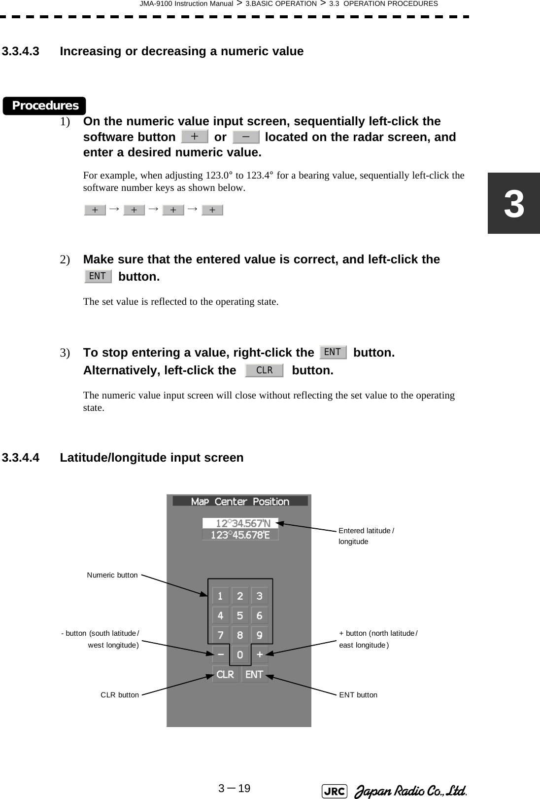
![JMA-9100 Instruction Manual > 3.BASIC OPERATION > 3.3 OPERATION PROCEDURES3-1733.3.3.7 Menu Operation with the Trackball 3.3.4 Operation on Numeric Value, Latitude / Longitude andCharacter Input menuWhen a numeric value must be entered while operating this radar system, the numeric value input screen will appear. In that case, enter a numeric value according to the following operation method.Press numeric keys corresponding to the desired item number to display the selected item.Press numeric keys corresponding to the desired item number to select a set value.Software buttonPress the[0]key to move to the higher level.When the [ > ] mark appears at the right end of a menu item, press numeric keys corresponding to the selected item number to move to a lower level.Item Selected itemCursorPresent state](https://usermanual.wiki/Japan-Radio/NKE1130.Users-Manual-1/User-Guide-994629-Page-137.png)
![3-18JMA-9100 Instruction Manual > 3.BASIC OPERATION > 3.3 OPERATION PROCEDURES3.3.4.1 Numeric value input screen 3.3.4.2 Directly entering a numeric valueProcedures1) On the numeric value input screen, sequentially left-click the software number keys located on the radar screen, and enter a desired numeric value.For example, when entering → → → for a bearing value, sequentially left-click the software number keys as shown below.2) Make sure that the entered value is correct, and left-click the button.The set value is reflected to the operating state.3) To stop entering a value, right-click the [ENT] button. Alternatively, left-click the button. The numeric value input screen will close without reflecting the set value to the operating state. Entered value+ buttonEnter buttonClear button- buttonNumeric button1234ENTCLR](https://usermanual.wiki/Japan-Radio/NKE1130.Users-Manual-1/User-Guide-994629-Page-138.png)
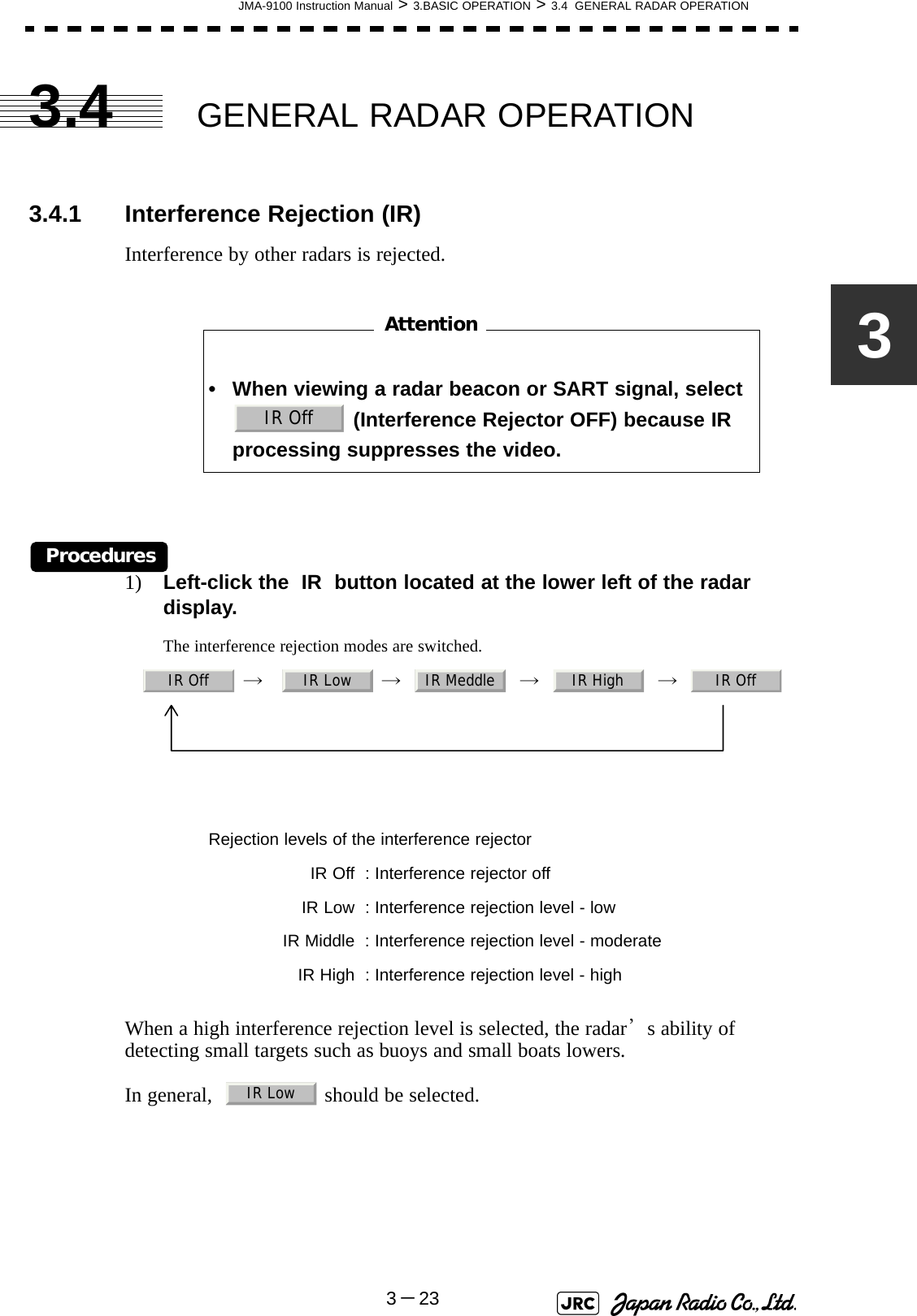
![3-24JMA-9100 Instruction Manual > 3.BASIC OPERATION > 3.4 GENERAL RADAR OPERATION3.4.2 Switch Transmitter Pulse Length [GAIN]Procedures1) Press [GAIN] dialValues of the transmitter pulse width are switched. Usable transmitter pulse width differs according to the type of antenna being used and the observation range being used. For usable pulse width, see Section 11.8 "SCANNER UNIT (NKE-1139)"~Section 11.14 "SCANNER UNIT (NKE-2103-6HS)". Effects of transmitter pulse widthWith selected: The transmitter pulse becomes shorter, and therange resolution improves. The effect ofsuppressing sea clutter returns and rain/snowclutter returns heightens.Recommended condition for selection: In bays/harbors where targets are denselycrowded. Rough sea state due to torrential rain orstormy weather.With selected: The normal transmitter pulse length is set. Bothrange resolution and gain are appropriately set.Recommended condition for selection: General navigationWith selected: The transmitter pulse becomes longer, and gainimproves. Small targets are zoomed and are easyto observe. When the sea state is bad, detectionperformance decreases.Recommended condition for selection: Detection of small targets in good weatherconditions.MP1 MP2 LP1 LP2SPMPLP](https://usermanual.wiki/Japan-Radio/NKE1130.Users-Manual-1/User-Guide-994629-Page-144.png)
![JMA-9100 Instruction Manual > 3.BASIC OPERATION > 3.4 GENERAL RADAR OPERATION3-2533.4.3 Target Enhance (ENH)The dimension of video display is enlarged to enhance a target.Procedures1) Left-click the ENH button located at the lower left of the radar display.The target enlargement levels are switched. ⇒ ⇒ ⇒ ⇒ In general, ENH Level1 or ENH Level2 should be selected.Effect of target enlargement :Expansion off Select this mode particularly whenresolution is required. :Expansion small Select this mode in general. Radar echoesare expanded by 1 scale in all directions. :Expansion medium Select this mode to easily view the radarvideo. Radar echoes are expanded by 2scales in all directions on the display. Expansion large Select this mode to detect small targetssuch as buoys. The expansion near ascreen center is added to ENH Level2.NOTE: When ENH Level3 is selected, sea clutter returns and rain/snow clutter returns are apt to be expanded. When using thisexpansion mode, operate [SEA] dial and [RAIN] dial tosuppress sea clutter returns and rain/snow clutter returns.ENH Off ENH Level1 ENH Level2 ENH Level3 ENH OffENH OffENH Level1ENH Level2ENH Level3](https://usermanual.wiki/Japan-Radio/NKE1130.Users-Manual-1/User-Guide-994629-Page-145.png)
![JMA-9100 Instruction Manual > 3.BASIC OPERATION > 3.4 GENERAL RADAR OPERATION3-2733.4.5 Switch Azimuth Display Mode (AZI MODE)Select the bearing for the radar video to be displayed on the radar display.Procedures1) Left-click the AZI Mode button located at the lower left of the display.The bearing display modes are switched. → → True Bearing Mode [North Up]The video is displayed so that the zenith of the PPI (0° on range rings) points to the due north. Fixed targets do not flicker and are easily identified on the chart, and the true bearing of a target can easily be read out.Relative Bearing Mode [Head Up]The video is displayed so that the ship’s heading line points to the zenith of the PPI (0° on range rings). Since targets are displayed in their directions relative to the ship’s heading line, the operator can view the video in the same field of view as in operating the ship at sea. This mode is suitable for watching over other ships.Course-up Bearing Mode [Course Up]By setting the course-up mode, own ship's course is fixed so that it is located on the zenith of the radar display (0° on range rings). In the same way as in the North-up mode, fixed targets do not flicker, and are stabilized even if the ship is yawing. The bearing of the heading line varies by the same shift of own ship’s course. To change the course, press the [AZI MODE] key several times again to select the course-up mode so as to set a new course.H Up N Up C UpHLNorth-up mode Head-up mode Course-up modeHLNorth HLNorth](https://usermanual.wiki/Japan-Radio/NKE1130.Users-Manual-1/User-Guide-994629-Page-147.png)
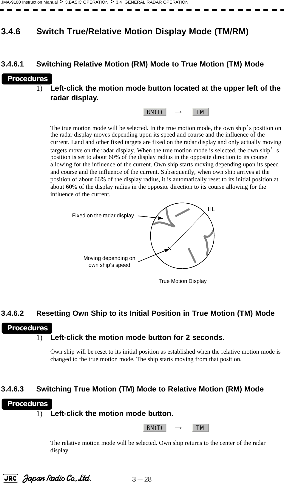
![JMA-9100 Instruction Manual > 3.BASIC OPERATION > 3.4 GENERAL RADAR OPERATION3-2933.4.7 Move Own Ship’s Display Position (Off Center)The own ship’s position can be moved from the display center to any position within 66% of the display radius. This function is convenient for observing a wide coverage in any direction.If Off Center functions set to scanner position is outside of the PPI range, when function switching display with reference to scanner position.Procedures1) Left-click the Off Center button located at the upper left of the display.The cross cursor mark will appear at the own ship’s position on the radar display.2) Move the cross cursor mark (own ship’s display position) to a desired position by using the trackball.While the cross cursor mark is moving, the own ship’s display position moves following the cross cursor mark.When it moves to a position outside 66% of the display radius, the center position is limited to a position within 66% of the display radius.3) Press the trackball button on the left key.The own ship’s display position will be fixed to the cross cursor mark.3.4.7.1 Returning Own Ship's Position to the CenterProcedures1) Left-click the Off Center button for 2 seconds.The own ship position is returned to the center of the display. This function is not available on the 96 NM range.iMove the cursor mark toa desired positionHLPress the [ENT]keyThe own ship’s display position will be fixed.HL](https://usermanual.wiki/Japan-Radio/NKE1130.Users-Manual-1/User-Guide-994629-Page-149.png)
![3-34JMA-9100 Instruction Manual > 3.BASIC OPERATION > 3.4 GENERAL RADAR OPERATION3.4.10 Hide/Display Range Rings [HL OFF]Procedures1) Press the [HL OFF] key. Alternatively, Left-click the button located at the lower right of the display.The ship's heading line (HL) is hidden while the [HL OFF] key is held down.The ship's heading line that indicates the course of own ship is always shown on the radar display. The heading line is hidden while the [HL OFF] key is held down, so the targets on the heading line can be easily observed.3.4.11 Hide Graphics Information on Radar Display [DATA OFF]Various graphics information such as target tracking TT/AIS symbols, NAV lines, and MAP information is shown on the radar display of this radar system, and may make it difficult to view the radar video. In that case, use this function to temporarily hide unnecessary graphics information.Procedures1) Press the [DATA OFF] key. Alternatively, Left-click the button located at the lower right of the display. While the key is pressed, graphics data other than VRM, EBL, HL, cross cursor mark, and range rings on the radar display is temporarily hidden.HLOffDataOff](https://usermanual.wiki/Japan-Radio/NKE1130.Users-Manual-1/User-Guide-994629-Page-154.png)
![JMA-9100 Instruction Manual > 3.BASIC OPERATION > 3.4 GENERAL RADAR OPERATION3-3533.4.12 Switch Day/Night Mode [DAY/NIGHT] Several combinations of the display color and brilliance according to the ambient lighting conditions are provided. The display color setting is easily changed.Procedures1) Press the [DAY/NIGHT] key. Alternatively, left-click the Day/Night button located at the lower right of the radar display.The DAY/NIGHT modes are switched. → → → ← ← ← The current mode is displayed at the lower right of the radar display.For how to set the display color and brilliance for each mode, see Section 3.8.5 "Set Radar Display (Display Setting)"3.4.13 Adjust Operation Panel Brilliance [PANEL] Adjust brilliance of the operation panel according to the ambient lighting conditions.Procedures1) Press the [PANEL] key. Alternatively, left-click the button located at the lower right of the radar display. In consideration of the ambient brightness, adjust panel brilliance that is high enough to read the characters on the operation panel but does not glare.The [PANEL] key lamp lights up irrespective of panel brilliance adjustment. Day1 Day2 Day3 DuskDay2 Day3 Dusk NightPanel○](https://usermanual.wiki/Japan-Radio/NKE1130.Users-Manual-1/User-Guide-994629-Page-155.png)
![3-46JMA-9100 Instruction Manual > 3.BASIC OPERATION > 3.5 USE OWN SHIP'S TRACK3.5.9 Use Tidal Current Track (Current Vector Track)Set the conditions for adding tidal current vectors to own ship's track by performing the operation below.Procedures1) Open the Current Setting menu by performing the menu operation below.→ The Current Setting menu will appear.Set the tidal current vector display conditions.[1]Length of the tidal current vector (Current Size)•Set the length of the tidal current vector.•The unit of measure is kn/cm.•If 1.0kn/cm is set, a tidal current of 1.0kn is shown as a one-centimeter lineon the radar display.[2]Color of the vector for tidal current layer A (Layer A)•Set the vector's display color for tidal current layer A.•Choose one of the following colorsWhite、Gray、Blue、Green、Yellow、Pink、Red[3]Color of the vector for tidal current layer B (Layer B)•Set the vector's display color for tidal current layer B.•Choose one of the following colorsWhite、Gray、Blue、Green、Yellow、Pink、Red[4]Color of the vector for tidal current layer C (Layer C)•Set the vector's display color for tidal current layer C.•Choose one of the following colorsWhite、Gray、Blue、Green、Yellow、Pink、Red Track8. Current Setting](https://usermanual.wiki/Japan-Radio/NKE1130.Users-Manual-1/User-Guide-994629-Page-166.png)
![JMA-9100 Instruction Manual > 3.BASIC OPERATION > 3.6 DISPLAY USER MAP3-4733.6 DISPLAY USER MAPUp to 20,000 items of NAV lines, coastlines, depth contours, and NAV marks can be created, displayed, loaded, and saved. (This function is available only when navigation equipment is connected to this radar system.)3.6.1 Create User Map (Mark/Line)In this system, when the radar is in the transmission state, the user map is displayed all the time. However, valid latitude/longitude data and true bearing data must be entered into the system.The user map can be created and edited by performing the following operation.3.6.1.1 Plotting a markProcedures1) Left-click the button located at the upper right of the display to set the Mark mode. The mark font to be used is displayed to the right of the button.Marks that can be used : 29 typesLines that can be used : 3 types (solid, broken, and dashed-dotted line)Color of mark and linesthat can be used : 7 colorsiIf radar video is poor visibility caused by user map function,press the [DATA OFF] key to map displays temporarily off.CursorCursor mode switching Mark color / line color switchingMark font / line pattern switchingCursor](https://usermanual.wiki/Japan-Radio/NKE1130.Users-Manual-1/User-Guide-994629-Page-167.png)
![3-60JMA-9100 Instruction Manual > 3.BASIC OPERATION > 3.6 DISPLAY USER MAP3) Left-click the button.The selected mark will be deleted. 3.6.4 Correct Position on User Map (Shift User Map)3.6.4.1 Correcting the display position on the user map (Shift)If the display position on the user map is different from an actual position, it can be changed to the correct position in manual mode.Procedures1) Open the [Shift] menu by performing the menu operation below. → is displayed for the Cursor mode, indicating that the user map shift mode is selected.2) Put the pointer on a mark or end of a line, coastline, or depth contour line, and left-click.3) Move the cross cursor mark to the location to be corrected, and left-click.Positions of all marks and lines currently displayed will be corrected.At this time, Map Shift is displayed in the map position correction (lower right of the display), indicating that the position is being corrected.NOTE: If data is not copied on the flash memory card (option), the datais not be reloaded.:Heading correction is conducted:Heading correction is not conducted1. YesU.Map3. ShiftShiftMap ShiftMap Shift](https://usermanual.wiki/Japan-Radio/NKE1130.Users-Manual-1/User-Guide-994629-Page-180.png)
![JMA-9100 Instruction Manual > 3.BASIC OPERATION > 3.6 DISPLAY USER MAP3-6133.6.4.2 Restoring the corrected user map to its original state (Shift Clear)Procedures1) Open the Mark Operations menu by performing the following menu operation.→ Only the most recently corrected data (for a single input) will be cleared, and the data will be displayed at its original position.At this time, Map Shift is not displayed in the map position correction (lower right of the display). 3.6.5 Save User Map3.6.5.1 Loading navigation data (Load User Map)Procedures1) Insert a flash memory card into the card slot.Flash memory card (option) is necessary.2) Open the File Operations menu by performing the following menu operation.→ 3) Left-click the item button of and select the card slot.Slot1 and Slot2 of the Select Card Slot items are switched.4) Left-click the item button of and select /. and of the Load Mode items are switched.When [Add] is selected, new data is added to the savedd data. When [Overwrite] is selected, the saved data is overwritten.:Heading correction is conducted:Heading correction is not conductedU.Map4. Shift ClearMap ShiftMap Shift U.Map7. File Operation1. Select Card Slot2. Load ModeAddOverwriteAddOverwrite](https://usermanual.wiki/Japan-Radio/NKE1130.Users-Manual-1/User-Guide-994629-Page-181.png)
![JMA-9100 Instruction Manual > 3.BASIC OPERATION > 3.6 DISPLAY USER MAP3-6533.6.6 Set and Display Geodetic System (Geodetic)To create navigation information, set the geodetic system that is used with the connected navigation equipment. When navigation information is loaded, the geodetic system used when the navigation information was saved, is displayed. Make sure that the displayed geodetic system is identical to the one used with the navigation equipment. If the two geodetic systems are different, the positions of navigation information on the radar display will be shifted. Therefore, it is important to set the geodetic system of the navigation equipment.[1] Setting the geodetic system for navigation data to be saved (Geodetic)Procedures1) Open the Geodetic menu by performing the following menu operation.→ The numeric value input screen for Geodetic will appear.2) Enter the desired geodetic system number.The geodetic system is determined.For how to input numeric datas on the numeric value input screen, see Section 3.3.4 "Operation on Numeric Value, Latitude / Longitude and Character Input menu".[2] Displaying the geodetic system of the navigation data being displayed (Geodetic)Procedures1) Load navigation data by referring to Section 3.6.5.1 "Loading navigation data (Load User Map)".2) Open the Mark Operations menu by performing the following menu operation.The geodetic system will be displayed in the field. U.Map6. GeodeticU.Map6. Geodetic](https://usermanual.wiki/Japan-Radio/NKE1130.Users-Manual-1/User-Guide-994629-Page-185.png)
![JMA-9100 Instruction Manual > 3.BASIC OPERATION > 3.7 USE ROUTE FUNCTION3-6733.7 USE ROUTE FUNCTIONIn this radar system, a destination mark set by navigation equipment can be displayed, and a simple route can be created, displayed, loaded and saved. (To use this function, navigation equipment must be connected to this system)3.7.1 Display Route/Destination Mark (Select Route)In this radar system, the following route and destination marks can be displayed.Procedures1) Left-click the button located at the lower right of the radar display.The Route Menu will appear.2) Set the item.The following route/destination mark display modes can be selected.iIf radar video is poor visibility caused by route function, click theMap button to turn off the Map function. Otherwise, press the[DATA OFF] key to map displays temporarily off.Route : Route created in the radar system are displayed.Destination mark : Destination marks sent from outside navigation equipment aredisplayed. : Route and destination marks are not displayed. : Route saved in the system are displayed.: Destination marks are displayed by using WPT data sentfrom outside navigation equipment.iTo display the mark on the radar display, selectNMEA .The destination mark is displayed only when the Waypoint datais received from outside by using the NMEA sentence(RMB,BWC,BWR).Route1. Select RouteOffInternalNMEA○WP](https://usermanual.wiki/Japan-Radio/NKE1130.Users-Manual-1/User-Guide-994629-Page-187.png)
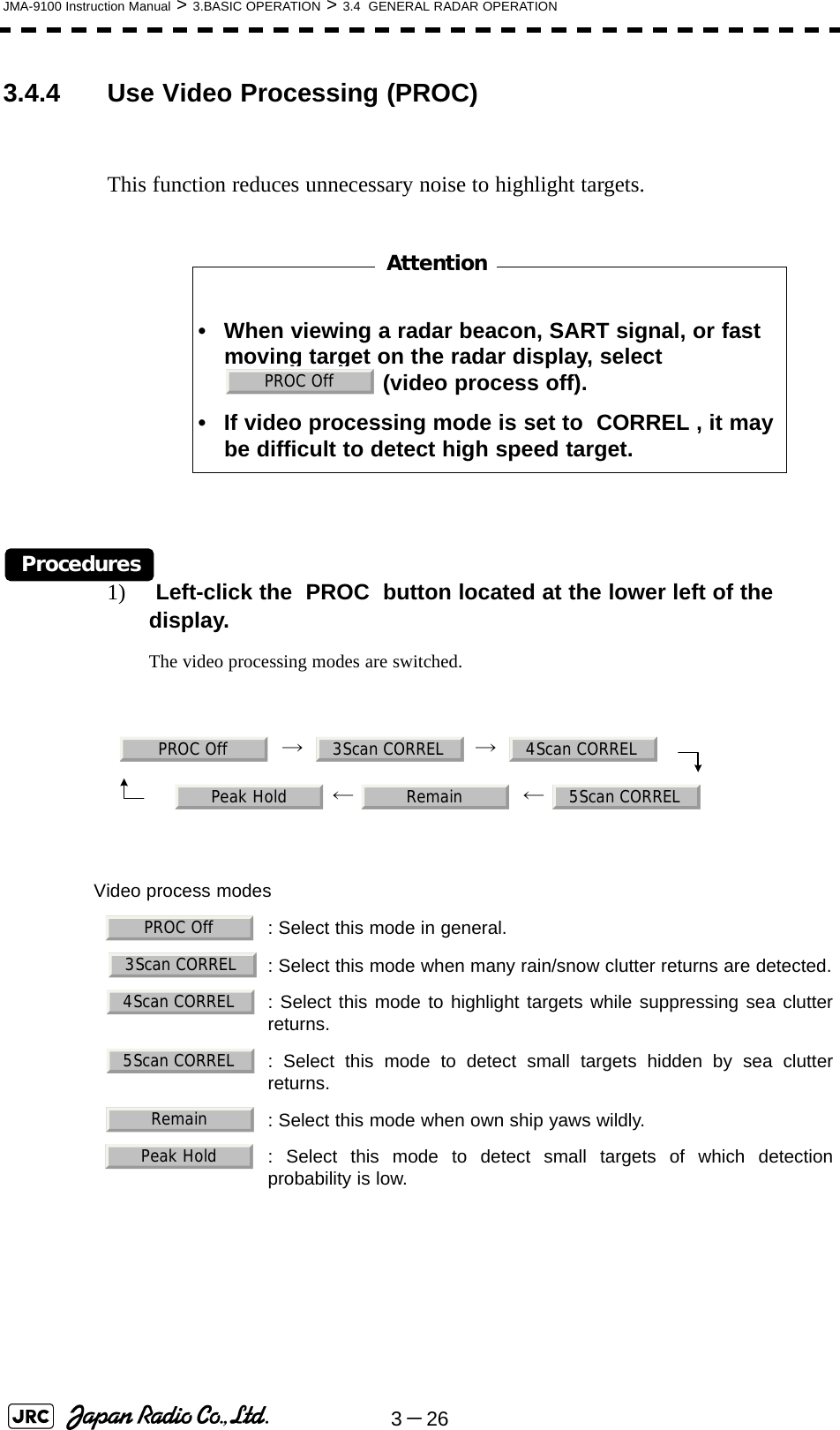
![JMA-9100 Instruction Manual > 3.BASIC OPERATION > 3.8 APPLIED OPERATIONS3-9333.8.1.4 Process Switch•This function sets a specific area and switches the video process mode between the inside and outside of the area.•In Section 3.8.1.5 "2nd Porcess Mode" 2nd Process Mode, set the second video process mode for the area outside the boundary.•In [2] PROCESS of Main Menu , set the first video process mode for the area inside the boundary.•Gain at a distance can be improved by suppressing near sea clutter through the correlative process.•There are two methods for setting an area:3.8.1.5 2nd Porcess Mode•Set the second video process mode for the outside of a specific area.•This function is enabled when or is selected in Section 3.8.1.4 "Process Switch".3.8.1.6 Process Switch Range•Set the boundary range of a specific area.•This function is enabled when is selected in Section 3.8.1.4 "Process Switch".•The specific area turns out to be a circle with the own ship’s position as the center.•The boundary range can be set in units of 0.1 nm, ranging 0.1 to 25.5 nm. :Disables the Process Switching function. (Standardsetting):Sets a boundary at a constant range from the center. Setthe boundary range in Section 3.8.1.6 "Process SwitchRange". The specific area turns out to be a circle with theown ship’s position as the center.:Automatically sets a specific area. The area subject tomany clutter returns is inside the boundary, and the arealess subject to clutter returns is outside the boundary.Video process modes : Select this mode in general. : Select this mode when many rain/snow clutter returns are detected.: Select this mode to highlight targets while suppressing sea clutter returns. : Select this mode to detect small targets hidden by sea clutter returns.: Select this mode when own ship yaws wildly. : Select this mode to detect small targets of which detection probability is low.OffRange FixAUTORange FixAUTOPROC Off3Scan CORREL4Scan CORREL5Scan CORRELRemainPeak HoldRange Fix](https://usermanual.wiki/Japan-Radio/NKE1130.Users-Manual-1/User-Guide-994629-Page-213.png)
![3-94JMA-9100 Instruction Manual > 3.BASIC OPERATION > 3.8 APPLIED OPERATIONS3.8.1.7 Fast Target Detection•This function displays fast moving targets that are suppressed in scan-correlative process mode.•This function is enabled when , , or is selected as the video process mode. •If unwanted waves remain on the radar display, suppress them by using the [SEA], [RAIN], or [GAIN] dial, or adjusting the interference rejection mode. : Disables the Fast Target Detection function.: Enables the Fast Target Detection function.3Scan CORREL 4Scan CORREL5Scan CORRELOffOn](https://usermanual.wiki/Japan-Radio/NKE1130.Users-Manual-1/User-Guide-994629-Page-214.png)
![3-98JMA-9100 Instruction Manual > 3.BASIC OPERATION > 3.8 APPLIED OPERATIONS3.8.3.4 Ice Class Standby Mode•In this mode, the antenna is rotated when transmission is in the standby state.•This mode is effective to prevent the antenna's rotating shaft from freezing. 3.8.4 Set Cursor (Cursor Setting)This function enables the setting of detail information about cursor operation and display.Procedures1) Open the Cursor Setting menu by performing the menu operation below.→ → → The Cursor Setting menu will appear.Detail information about cursor operation and display can be set by changing the settings of the menu items.3.8.4.1 EBL/VRM Control CURS•The EBL/VRM Control Cursor is switched between Valid and Invalid.•The trackball is provided as a standard device. If the trackball malfunctions, the cursor can be moved by using the [EBL] dial and [VRM] dial.•The cursor moves horizontally when [EBL] is operated, and moves vertically when [VRM] is operated.•To switch between EBL/VRM operation and cursor operation while ON is selected, hold down the [EBL] dial for 2 seconds. :The ice class standby mode is not used. When transmission isin the standby state, the antenna also stops rotating. :The ice class standby mode is used. When transmission is inthe standby state, the antenna rotates. : Cursor is operated using a [EBL] [VRM] dial. : Cursor is operated using a trackball.OffOnMain7. Sub Menu9. EBL/Cursor Setting3. Cursor SettingOnOff](https://usermanual.wiki/Japan-Radio/NKE1130.Users-Manual-1/User-Guide-994629-Page-218.png)
![JMA-9100 Instruction Manual > 3.BASIC OPERATION > 3.8 APPLIED OPERATIONS3-10333.8.7 Set User Option Keys [OPTION 1/2]Users can freely make settings with [OPTION 1] key and [OPTION 2] key.By using the keys, users can open a frequently used menu by only single operation, or assign special functions, to the user key switches.3.8.7.1 Initial Setting (Option Key Setting)Set functions that can be performed with the option key switches.Procedures1) Open the Option Key Setting menu by performing the menu operation below.→ → The Option Key Setting menu will appear.This system provides two user keys: [OPTION 1] and [OPTION 2]. Different functions can be allocated to each key. Functions that can be allocated to each key are as follows: : A specific menu is directly displayed. : The zoom display function is switched between on and off. : Set/Cancel Waypoint menu key : Start-point, Pass-point key in simple route operating : End-point key in simple route operating : Screen capture key (This function is enabled only when thecard (optional) is connected.)Main7. Sub Menu4. Option Key SettingMenuZoomDEST->○○->Capture Screen](https://usermanual.wiki/Japan-Radio/NKE1130.Users-Manual-1/User-Guide-994629-Page-223.png)
![3-104JMA-9100 Instruction Manual > 3.BASIC OPERATION > 3.8 APPLIED OPERATIONS3.8.7.2 Using Option Keys (Directly displaying a specified )Preset the that is to be displayed with the option key switch.Procedures1) Perform the general menu open procedure to open the menu that is to be directly displayed with Option Key.2) While the menu is open, hold down [OPTION 1] key or [OPTION 2] key for 2 seconds.The menu currently being displayed is saved for the pressed option key. 3.8.7.3 How to use the Optin key ( Display)Preset whether to execute the display by operating the user key.Procedures1) Press either [OPTION 1] key or [OPTION 2] key for which has been set.The zoom mode is activated.2) Put the cursor on a location that is to be zoomed, and left-click.Zoom is set.Cancel1) Press either [OPTION 1] key or [OPTION 2] key for which has been set.The zoom mode is cancelled and a normal display will appear. iThe menu set for the pressed option key will open.Subsequently, general menu operation can be performed.MenuMenuZoomZoomZoomZoom](https://usermanual.wiki/Japan-Radio/NKE1130.Users-Manual-1/User-Guide-994629-Page-224.png)
![3-106JMA-9100 Instruction Manual > 3.BASIC OPERATION > 3.8 APPLIED OPERATIONS•Navigation information of the water depth, water temperature, tidal current, wind direction/velocity, and destination is displayed with numeric values.•Left-click the button located at thelower righit of the display. The navigation data display function is switched between On and Off. 3.8.8.3 Depth Graph Setting •The Depth Graph Setting menu will appear.[1] Depth Graph Display•Determine whether to display received water depth information with a graph.•One of two digital information areas is used to display data.•When the water-depth graph is displayed, the sizes of the target tracking (TT)/AIS numeric data display areas are exclusively decreased.•Left-click the button located at thelower righit of the display. The water-depth graph display function is switched between On and Off.[2] Depth Range•Select the depth range on the water depth graph.[3] Time Range•Select the time range on the water depth graph.: Does not display the numeric values of navigation information.: Displays the numeric values of navigation information in digital information area 1.: Displays the numeric values of navigation information in digital information area 2.: Does not display a water depth graph.: Displays the water depth graph in digital information area 1.: Displays the water depth graph in digital information area 2.: Sets 50 m as the depth range.: Sets 100 m as the depth range.: Sets 250 m as the depth range.: Uses the depth range in the DPT sentence included inreceived data.TargetOffArea1Area2TargetOffArea1Area250m100m250mAUTO](https://usermanual.wiki/Japan-Radio/NKE1130.Users-Manual-1/User-Guide-994629-Page-226.png)
![JMA-9100 Instruction Manual > 3.BASIC OPERATION > 3.8 APPLIED OPERATIONS3-1073 [4] Depth Unit•Set the unit of water depth for the water-depth graph.3.8.8.4 Wind Graph Setting •The Wind Graph Setting menu will appear.[1] Wind Graph Display•Determine whether to display received wind direction/velocity information with a graph.•One of two digital information areas is used to display data.•When the wind direction / speed graph is displayed, the sizes of the target tracking (TT) / AIS numeric data display areas are exclusively decreased.•Left-click the button located at thelower righit of the display. The wind direction / speed graph display function is switched between On and Off.[2] Wind Speed Unit•Set the unit of wind velocity for the wind direction / speed graph.: Sets 10 minutes as the time range.: Sets 15 minutes as the time range.: Sets 30 minutes as the time range.: Sets 60 minutes as the time range.: Sets 12 hours as the time range.: The foot is used as the unit of water depth.: The fathom is used as the unit of water depth.: The meter is used as the unit of water depth.: Does not display the wind direction / speed graph.: Displays the wind direction / speed graph in digital information area 1.: Displays the wind direction / speed graph in digital information area 2.: Meters per second are used as the unit of wind speed.: Kirometers per hour are used as the unit of wind speed.: Knots are used as the unit of wind speed.10min15min30min60min12hourFeetFathomMetersTargetOffArea1Area2m/skm/hkn](https://usermanual.wiki/Japan-Radio/NKE1130.Users-Manual-1/User-Guide-994629-Page-227.png)
![3-108JMA-9100 Instruction Manual > 3.BASIC OPERATION > 3.8 APPLIED OPERATIONS3.8.8.5 TEMP Graph Setting •The TEMP Graph Setting menu will appear.[1] TEMP Graph Display•Determine whether to display the graph of the water-temperature data that has been received on the radar display.•One of two digital information areas is used to display data.•When the water-temperature graph is displayed, the sizes of the target tracking (TT)/AIS numeric data display areas are exclusively decreased.•Left-click the button located at thelower righit of the display. The water-temperature graph display function is switched between On and Off.[2] TEMP Graph Color•Set the color for the water-temperature graph.•There are eight selection items: , , , , , , [3] TEMP Range•When Color is selected for the display color for the water-temperature graph, set the temperature range of each color. [4] Time Range•Set the time range for the water-temperature graph.: The water-temperature graph is not displayed.: The water-temperature graph is displayed in digital information area 1.: The water-temperature graph is displayed in digital information area 2.: The time range is set at 10 minutes.: The time range is set at 15 minutes.: The time range is set at 30 minutes.: The time range is set at 60 minutes.: The time range is set at 12 hours.TargetOffArea1Area2White Gray Blue Green Yellow Pink Red10min15min30min60min12hour](https://usermanual.wiki/Japan-Radio/NKE1130.Users-Manual-1/User-Guide-994629-Page-228.png)
![JMA-9100 Instruction Manual > 3.BASIC OPERATION > 3.8 APPLIED OPERATIONS3-10933.8.8.6 Course Bar Setting•The Course Bar Setting menu will appear.[1] Course Bar Display•Determine whether to display the bar graph for the course data that has been received on the radar display.•One of two digital information areas is used to display data.•When the course-bar graph is displayed, the sizes of the target tracking (TT)/AIS numeric data display areas are exclusively decreased.•Left-click the button located at the lower righit of the display. The course bar display function is switched between On and Off.[2] Autopilot Course•Determine which field of the APB sentence that has been received is used to display AP course.[3] ROT Scale•Set the maximum scale for the TURN Rate graph. : The course bar graph is not displayed.: The course bar graph is displayed in digital information area 1.: The course bar graph is displayed in digital information area 2.:Heading to Steer to Destination:Bearing Origin to Destination:Bearing, Present Postion to Destination : The scale is set at ±30°/min.: The scale is set at ±60°/min.: The scale is set at ±90°/min.: The scale is set at ±120°/min.: The scale is set at ±150°/min.: The scale is set at ±300°/min.TargetOffArea1Area2Course to SteerFrom OriginFrom CURR POSN30-0-3060-0-6090-0-90120-0-120150-0-150300-0-300](https://usermanual.wiki/Japan-Radio/NKE1130.Users-Manual-1/User-Guide-994629-Page-229.png)
![JMA-9100 Instruction Manual > 3.BASIC OPERATION > 3.9 USE FUNCTION KEY [USER]3-11133.9 USE FUNCTION KEY [USER]"Radar Function Setting" is provided for easily obtaining the best radar video by storing complex radar signal processing settings in the optimum status by use, and calling the setting in accordance with the conditions for using the function.Functions are factory-set for general use, and the settings can be fine adjusted by operating the menu.Four function modes are available, and they are factory-set as follows:3.9.1 Operation Procedures3.9.1.1 Calling a FunctionProcedures1) Press the [USER] key.Each time the [USER] key is pressed, the selection changes cyclically as follows:Function Off→Function1→Function2→Function3→Function4→Function OffThe name of the current function mode is displayed at the lower left of the display.Alternatively, left-clicking the function button located at the lower left of the radar display will enable the same operation.3.9.1.2 Changing Function Setting (temporary change)When radar signal processing setting is changed by using the menu or button on the radar display while function 1 to 4 is called, the change is temporarily reflected to the operating state.Since this method does not change the memory contents, the new setting is discarded as soon as another function is called.When the previous function is called again, operation is performed according to the memory contents.Function 1: Useful for observing short-range videos.Function 2: Suitable for general ocean navigation.Function 3: Useful for observing videos in stormy weather.Function 4: Use this mode when sea clutter is not strong butrain / snow clutter is strong.CoastDeep SeaStormRainFunction (FUNC) mode](https://usermanual.wiki/Japan-Radio/NKE1130.Users-Manual-1/User-Guide-994629-Page-231.png)
![3-112JMA-9100 Instruction Manual > 3.BASIC OPERATION > 3.9 USE FUNCTION KEY [USER]3.9.1.3 Changing Function Setting (memory contents change)To change the memory contents of functions 1 to 4, use the function setting menu.For how to operate the function setting menu, see Section 3.9.3 "Overview of Function Operations (User Function Setting)". 3.9.2 Function Setting Menu ItemsThe function setting menu has the items below.page 1 Option1. Mode Name of the mode to be used Coast/Deepsea/....2. IR Radar interference rejection Off/Low/Middle/High3. Process Video process PROC Off/3Scan CORREL/....4. Target Enhance Target expansion Off/Level1/Level2/Level35. AUTO Sea/Rain Automatic clutter suppression Off / AUTO Sea / AUTO Sea/Rain6. Save Present State Saving the present statepage 2 Option1. Pulse Length 0.75NM Standard pulse length for 0.75nm range SP1/MP12. Pulse Length 1.5NM Standard pulse length for 1.5nm range SP1/MP1/MP2/MP33. Pulse Length 3/4NM Standard pulse length for 3nm range MP1/MP2/MP3/LP14. Pulse Length 6/8NM Standard pulse length for 6nm range MP1/MP2/MP3/LP1/LP25. Pulse Length 12NM Standard pulse length for 12nm range MP1/MP2/MP3/LP1/LP26. Pulse Length 16NM Standard pulse length for 16nm range MP1/MP2/MP3/LP1/LP2page 3 Option1. Video Latitude Dynamic range of radar video Narrow/ Normal /Wide/Super Wide2. Video Noise Rejection Radar video noise rejection Off/Level1/Level23. AUTO Dynamic Range Automatic dynamic range control Off/On4. Process Switch Radar video process switching Off/Range FIX/AUTO5. 2nd Process Mode 2nd video process mode PROC Off/3Scan CORREL/....6. Process Switch Range Video process switching range7. Fast Target Detection Off/Onpage 4 Option1. Trails Interval Radar trails length Off/15sec/....2. Trails Mode True/Relative3. Trails Reference Level Radar trails plotting threshold Level1-44. Trails Reduction Thinning of radar trails Off/Level1-36. Trails Process Superimpose-display of time radar trails andcontinuous radar trails. Off/On7. Max Interval Maximum time for radar trails display Short/Middle/Longpage 5 Option1. Gain Offset Gain correction2. PRF Transmitting repetition frequency Normal/Economy/High Power3. Small Buoy Detection Small target detection mode Off/On4. Fishnet Detection Fishnet detection mode Off/On5. Antenna Height Default/-5m/5-10m/10-20m/20m8. Set Mode Default9. Initialize](https://usermanual.wiki/Japan-Radio/NKE1130.Users-Manual-1/User-Guide-994629-Page-232.png)
![JMA-9100 Instruction Manual > 3.BASIC OPERATION > 3.9 USE FUNCTION KEY [USER]3-11333.9.3 Overview of Function Operations (User Function Setting)The following outlines the operation of each function selected from the function setting menu:Procedures1) Open the Process Setting menu by performing the menu operation below.→ → → The User Function Setting menu will appear.Specify the number for the function for which the settings are to be changed.The following are the operation overviews of each function setting item.page 1-[1] Mode•Selects the function name to be indicated at the lower left of the radar display when the function is selected.•When the setting is changed back to the factory setting, the initial value of the selected mode is called.•The following 11 modes are provided: : Use this mode to monitor a relatively short range, for example, baysand coasts where many boats and ships are running. (Importance isattached to resolution.): Use this mode to monitor a relatively long range, for example, the opensea. (Importance is attached to long-range gain.): Use this mode to detect small targets such as fishnets of round haulnetters hidden by sea clutter returns. (Importance is attached to seaclutter suppression, and gain to moving targets lowers.): Use this mode when many rain / snow clutter returns or sea clutterreturns are detected in stormy weather. (Importance is attached to rain /snow clutter and sea clutter suppression, and gain slightly lowers.) : Use this mode when only a few rain / snow clutter returns or sea clutterreturns are detected. : Use this mode when sea clutter is not strong but rain / snow clutter isstrong. (Importance is attached to rain / snow clutter suppression, andgain slightly lowers.): Use this mode to detect flocks of sea birds. : Use this mode to monitor utmost distances in the broad ocean.: Use this mode to detect small targets like radio buoys in areas outsidethe sea clutter area. (This mode displays targets of which detectionprobability is low.) : General mode used when the nine modes above are not applicable. : General mode used when the nine modes above are not applicable.Main3. RADAR Menu1. Process Setting8. User Function SettingCoastDeep SeaFish NetStormCalmRainBirdLongBuoyUser1User2](https://usermanual.wiki/Japan-Radio/NKE1130.Users-Manual-1/User-Guide-994629-Page-233.png)
![3-114JMA-9100 Instruction Manual > 3.BASIC OPERATION > 3.9 USE FUNCTION KEY [USER]page 1-[2] IR (Radar interference rejection)•Same function as IR Setting described in Section 3.4.1 "Interference Rejection (IR)".page 1-[3] Process (Video process)•Same function as PROCESS Setting described in Section 3.4.4 "Use Video Processing (PROC)" page 1-[4] Target Enhance•Same function as TARGET ENHANCE Setting described in Section 3.4.3 "Target Enhance (ENH)".page 1-[5] Auto STC/FTC (Auto Sea/Rain)•Detects unwanted waves such as rain/snow clutter and sea clutter and automatically suppresses them.•When the sea state or weather changes, this function automatically performs suppression processing in accordance with the situation.•Suppression processing is not full automatic, and requires the operator to adjust the afterimages of unwanted waves.•To adjust the afterimage of sea clutter, use the [SEA] dial.•To adjust the afterimage of rain/snow clutter, use the [RAIN] dial.•In areas where the density of unwanted waves is low, unwanted waves may remain being judged as targets. Thus, use the automatic clutter suppression mode together with the video process mode.•Characteristics of the automatic clutter suppression function: : Disables the automatic clutter suppression function. Select offwhen rain / snow clutter and sea clutter are not strong or when theship is in a bay. : Automatically detects the strength of sea clutter, and performs themost suitable sea clutter suppression processing. Even when the strength of sea clutter varies depending on the winddirection, AUTO Sea performs the most suitable suppressionprocessing. Land like islands can be displayed naturally. Since rain clouds outside sea clutter areas are recognized as land,there is no effect of suppressing rain / snow clutter. : Along with AUTO Sea, AUTO Rain automatically detects thestrength of rain / snow clutter, and performs the most suitable rain /snow clutter suppression processing. When rain clouds are scattered about, AUTO Rain performs rain /snow clutter suppression processing for only the rain-cloud areas. Since land is recognized as rain clouds, land videos becomeobscure.OffAUTO SeaAUTO Sea/Rain](https://usermanual.wiki/Japan-Radio/NKE1130.Users-Manual-1/User-Guide-994629-Page-234.png)
![JMA-9100 Instruction Manual > 3.BASIC OPERATION > 3.9 USE FUNCTION KEY [USER]3-1153page 2-[1]~[7] PL (Pulse Length)•Sets the standard transmitter pulse length in each range.•When the range is called, the pulse range is used.page 3-[1]~[7] Video setting menu (Process Setting)•Operation is the same as that of the Process Setting menu described in Section 3.8.1 "Set Radar Signal Processing (Process Setting)".page 4-[1]~[7] Radar trails settings (Trails Setting)•Same functions as in the Trails Setting of the RADAR Menu described in Section 3.8.2 "Set Radar Trails (RADAR Trails Setting)". page 5-[1] Gain Offset•Corrects gain while the function mode is called.•Since the displayed noise level varies depending on the combination of the video process mode and the interference rejection level, gain needs fine adjustment for always obtaining the highest level.•The gain correction function saves the correction value set by the gain adjust in each function mode, so it can obtain the highest gain without the gain adjust being operated when the function mode is changed.•To set high gain, set a value on the “+” side.•To set low gain, set a value on the “-” side.•When the radar interference rejection level is increased, the noise level is lowered. Thus, set a gain correction value to the “+” side.•When the video process mode , , or is used, the noise level is lowered. Thus, set a gain correction value to the “+” side.•When the video process mode or is used, noise is hard to disappear. Thus, set a gain correction value to the “-” side.page 5-[2] PRF•Same function as in the TXRX Setting described in Section 3.8.3 "Set Scanner Unit (TXRX Setting)".3Scan CORREL4Scan CORREL5Scan CORRELRemain Peak Hold](https://usermanual.wiki/Japan-Radio/NKE1130.Users-Manual-1/User-Guide-994629-Page-235.png)
![3-116JMA-9100 Instruction Manual > 3.BASIC OPERATION > 3.9 USE FUNCTION KEY [USER]page 5-[3] Small Buoy Detection•Reduces the loss of signal processing during detection of small targets.page 5-[4] FishNet Detection•Use this mode to detect small targets hidden by sea clutter returns.•This function becomes more effective when the AUTO RAIN clutter suppression function is used together.page 5-[5] Antenna Height•Set the height of radar antenna above sea level.•The STC/FTC curve is changed. :Activates the general signal processing mode. :Activates the small buoy detection mode that reduces the lossof signal processing. :Activates the general signal processing mode. :Activates the fishnet detection mode. : Set default : Set the antenna height under 5m.: Set the antenna height 5m to 10m.: Set the antenna height 10m to 20m.: Set the antenna height over 20m.OffOnOffOnDefault~5m5m~10m10m~20m20m~](https://usermanual.wiki/Japan-Radio/NKE1130.Users-Manual-1/User-Guide-994629-Page-236.png)
![JMA-9100 Instruction Manual > 3.BASIC OPERATION > 3.9 USE FUNCTION KEY [USER]3-11733.9.4 Overview of saved Function Setting DataThe overview of saved function setting data is as follows:Procedures1) Open the User Function Setting menu by performing the menu operation below.→ → → page 1-[1] Mode•Calls the default value of the mode, and saves it for the function number.page 1-[6] Save Present State•The currently operating state can be saved for the function number.•Use this function to save the state of good setting that will be frequently used.page 5-[8] Set Mode Default•Saves the setting of the current function number, as the default setting of the mode.page 5-[9] Initialize•Changes the memory contents of the mode, which is used with the current function number, back to the factory setting. Factory-set data: : Saved data that general operation cannot changeDefault data: : Standard data of each function mode that users can changeData that can be called: : Saved data that can be called by pressing the [USER] keyMain3. RADAR Menu1. Process Setting8. User Function SettingCoastDeepseaFishnetStormCalmRainBirdLongBuoyUser1User2CoastDeepseaFishnetStormCalmRainBirdLongBuoyUser1User2FUNC1FUNC2FUNC3FUNC4Present【USER】FUNCTION SETTINGFactory-set dataFUNCTION SETTINGDefault dataFUNCTION SETTINGData that can be called Current data5-[81-[15-[91-[6](https://usermanual.wiki/Japan-Radio/NKE1130.Users-Manual-1/User-Guide-994629-Page-237.png)
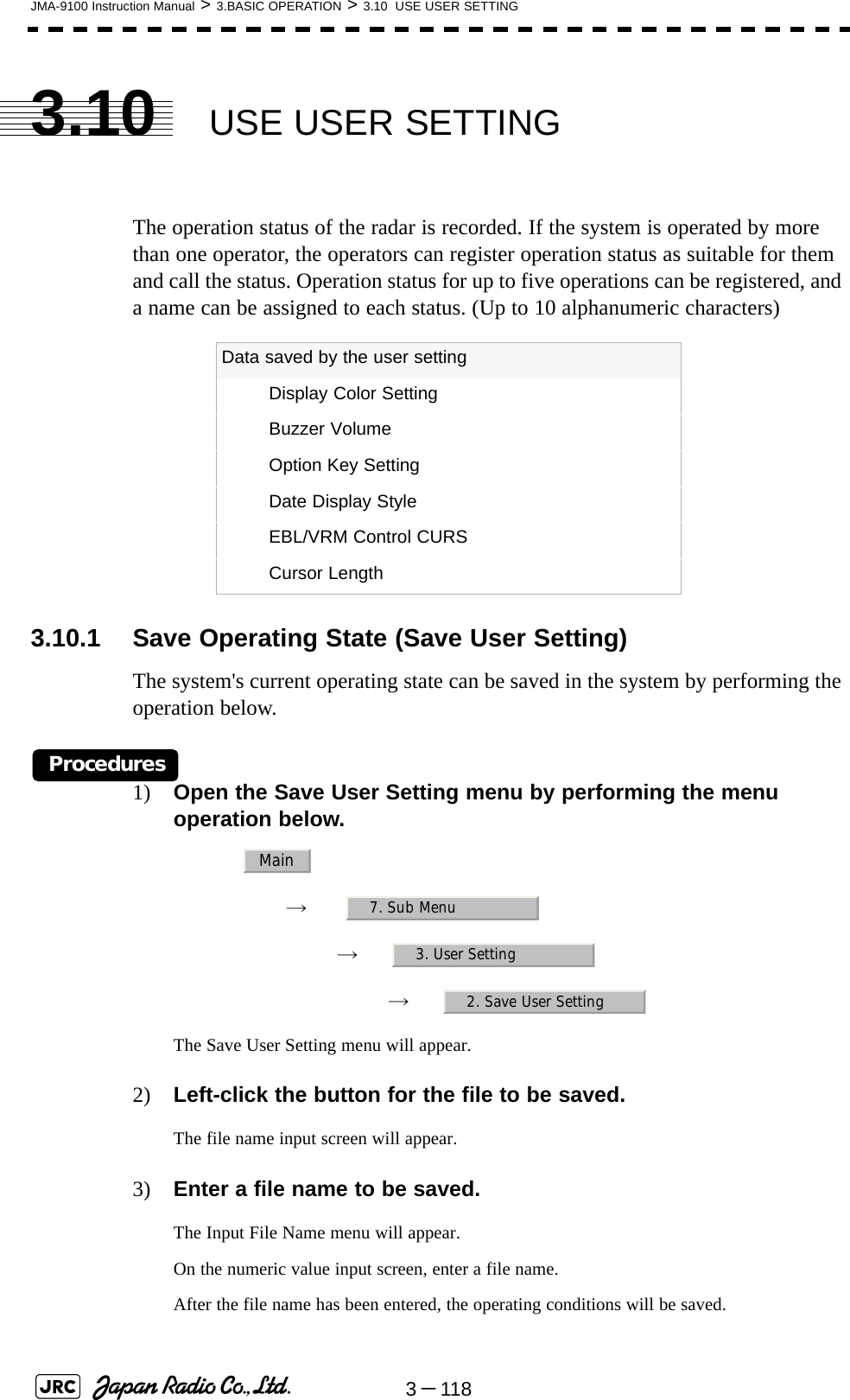
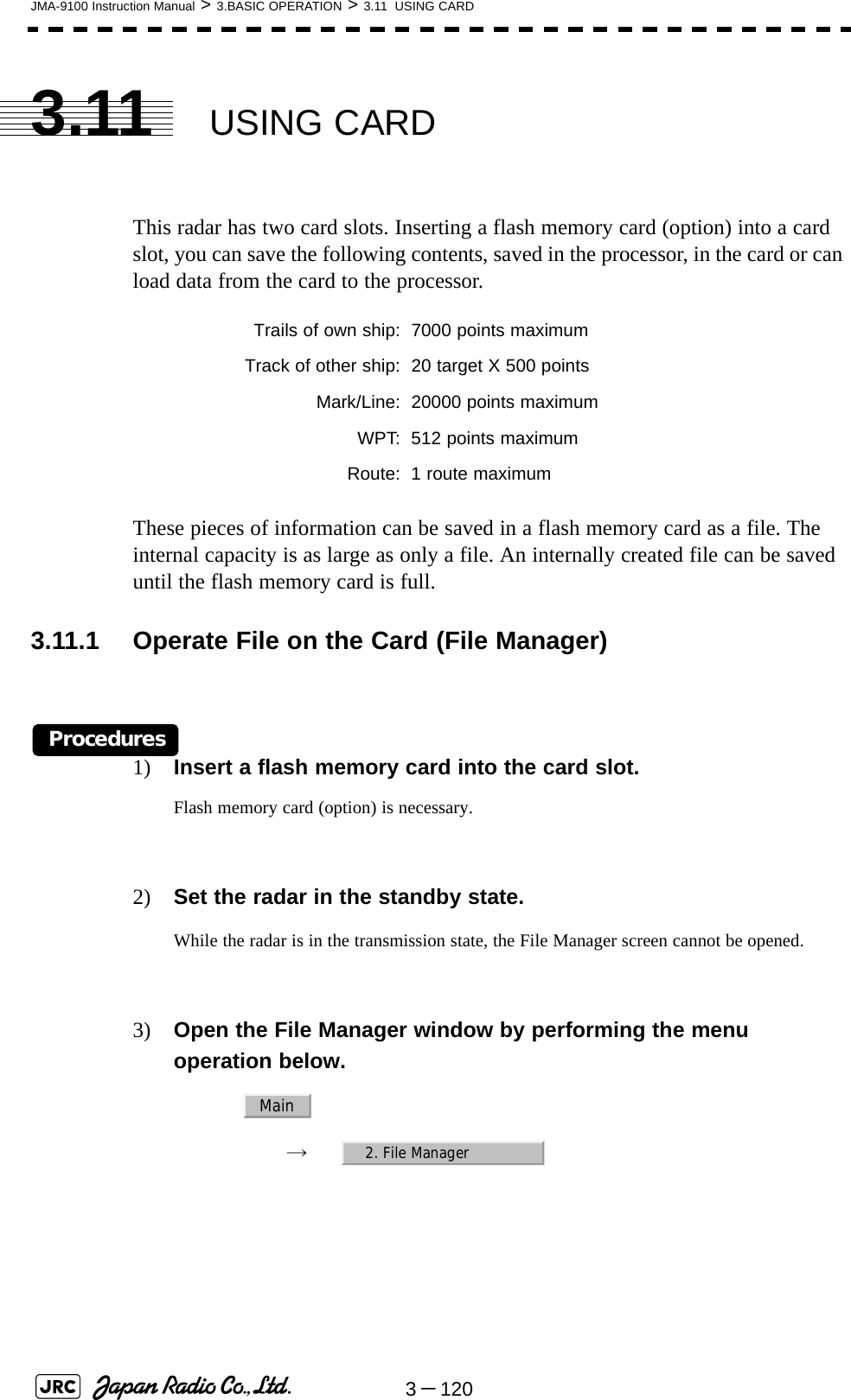
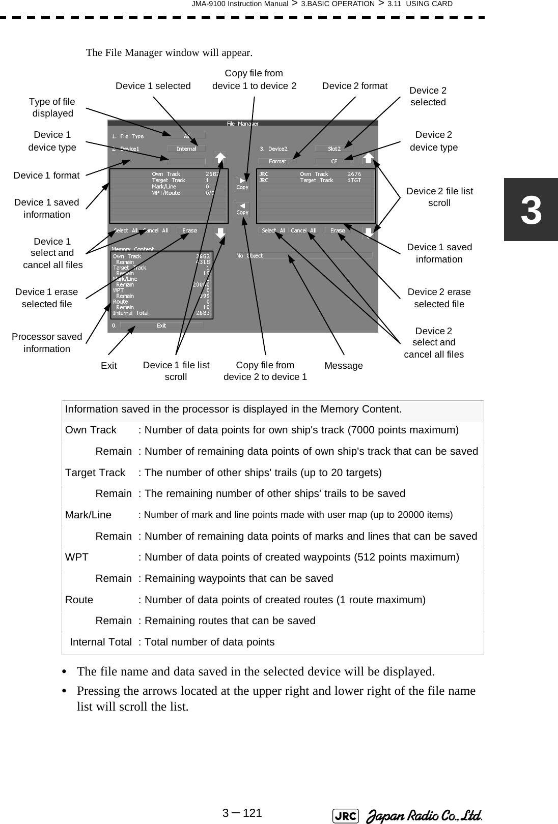
![MEASUREMENT OF RANGE AND BEARING4.1 USE OF NAVIGATION TOOLS ..............................................................4-14.1.1 Using Cursor (Cursor) ....................................................................4-24.1.2 Using Range Rings (Range Rings) ................................................4-24.1.3 Using Electronic Bearing Line (EBL1/EBL2) ................................4-34.1.4 Using Parallel Index Lines (PI Menu) .............................................4-84.1.5 Operating EBL Maneuver Function (EBL Maneuver Setting) ....4-144.1.6 Operating EBL, VRM, and PI with Cursor ...................................4-164.2 MEASUREMENT OF RANGE AND BEARING ....................................4-194.2.1 Measurement with Cursor Position (Cursor) ..............................4-194.2.2 Measurement with Electronic Bearing Line and Variable Range Marker [EBL] [VRM] .....................................................................4-204.2.3 Measurement with Two Arbitrary Points .....................................4-21SECTION 4MEASUREMENT OF RANGE ANDBEARING](https://usermanual.wiki/Japan-Radio/NKE1130.Users-Manual-1/User-Guide-994629-Page-247.png)
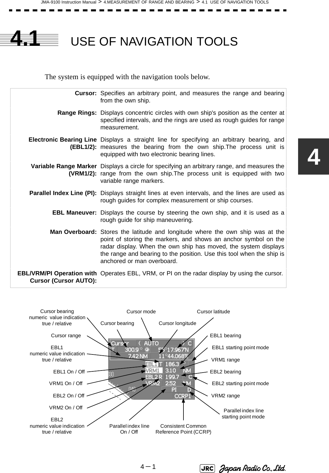
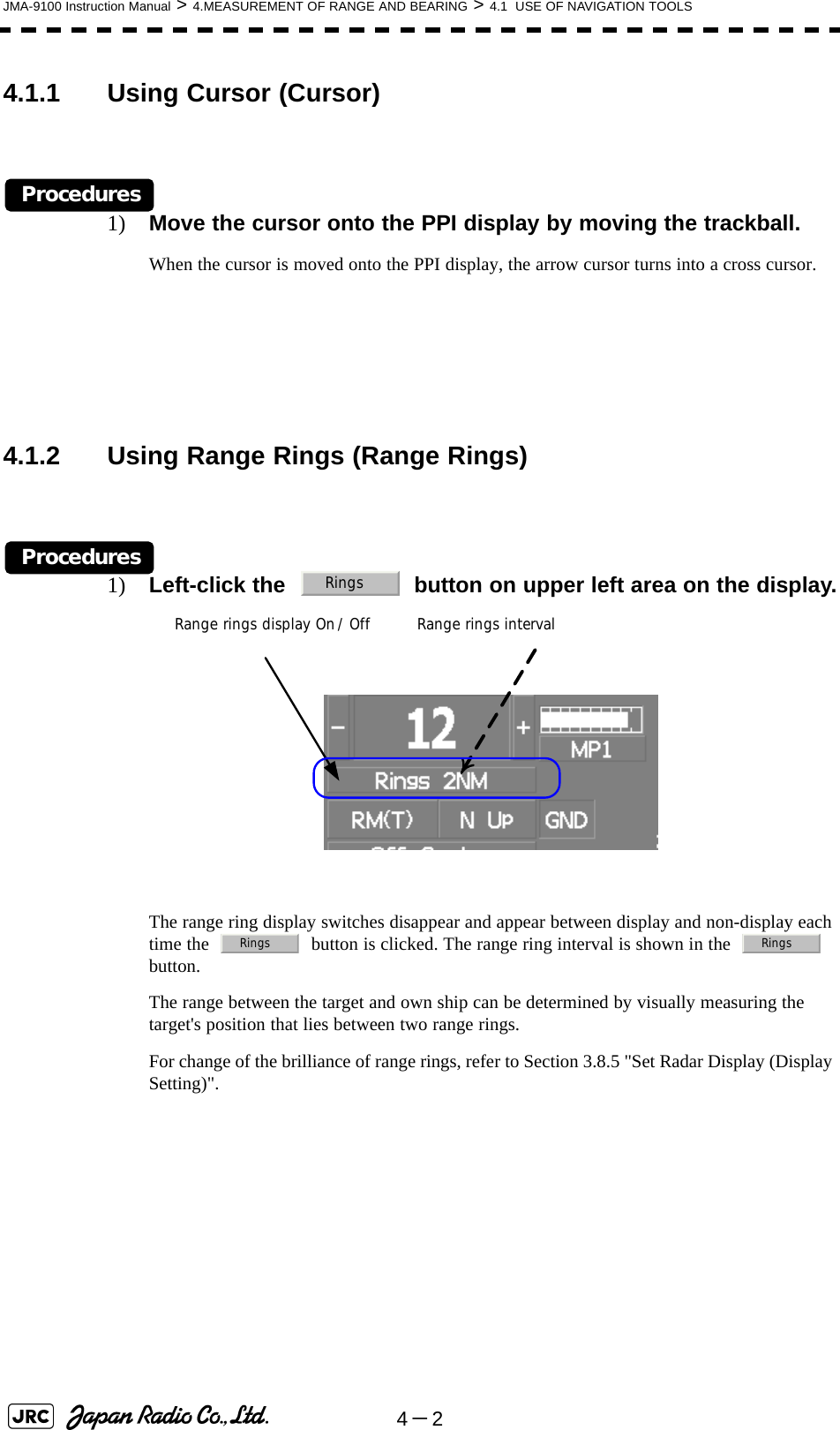
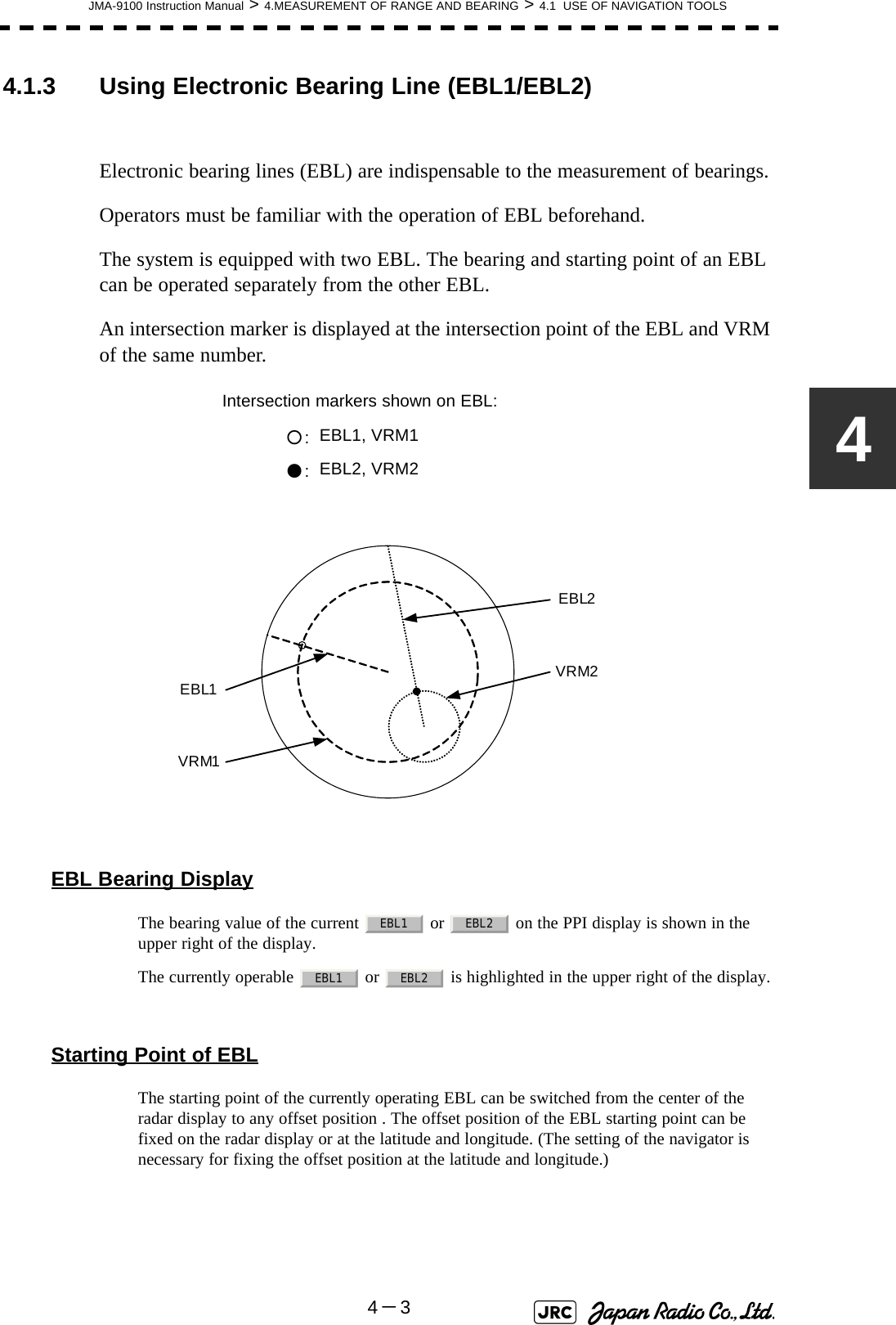
![4-4JMA-9100 Instruction Manual > 4.MEASUREMENT OF RANGE AND BEARING > 4.1 USE OF NAVIGATION TOOLS4.1.3.1 Operating EBL (EBL)Procedures1) Press the [EBL1] or [EBL2] key.The EBL button (located at the upper right of the display) will be highlighted, and the selected EBL becomes operable.Turn the [EBL] dial.To turn the [EBL] dial to the right, turn the EBL control clockwise; to turn the [EBL] dial to the left, turn the EBL control counterclockwise.Cancel1) Press the [EBL1] or [EBL2] key again.The selected EBL display will disappear.4.1.3.2 Moving the Starting Point of EBLThe system provides three types of EBL starting points. Select one of them in accordance with purpose.[1] To move the starting point of EBLProcedures1) Make EBL1 or EBL2 operable.2) Press the [EBL] dial to set or for the EBL1 / EBL2 starting point mode switching located at the upper right of the display.The selected EBL starting point mode is switched as shown below each time the dial is pressed. ⇒ ⇒ ⇒ 3) Put the cursor on the EBL starting point is to be moved, and left-click.The selected EBL starting point will be determined. : The EBL starting point is defined as the own ship's position.: The EBL starting point is moved and fixed on the radar display.: The EBL starting point is moved and fixed at the latitude andlongitude. (The navigator needs to be connected.)_CDC D_C D _](https://usermanual.wiki/Japan-Radio/NKE1130.Users-Manual-1/User-Guide-994629-Page-252.png)
![JMA-9100 Instruction Manual > 4.MEASUREMENT OF RANGE AND BEARING > 4.1 USE OF NAVIGATION TOOLS4-54[2] To return the EBL starting point to own ship's positionProcedures1) Make EBL1 or EBL2 operable.2) Press the [EBL] dial to set for the EBL1 / EBL2 starting point mode switching located at the upper right of the display.The selected EBL starting point will be set as the own ship's position.4.1.3.3 Setting EBL Operation Mode[1] To set the numeric value display mode of EBL (EBL Bearing REF)Determine whether to display EBL in true bearing mode or relative bearing mode.Procedures1) Put the cursor on the EBL1/2 numeric value indication true / relative switching (located at the upper right of the display), and left-click.The selected mode is switched as shown below each time the left button is clicked. ⇒ ⇒ [2] To set a mode for fixing EBL display (EBL Bearing Fix)When this function is set to Angle , an EBL is fixed to the preset bearing. For example, if a true bearing of 020° is preset, the EBL is fixed to the true bearing 020° even when the own ship turns.When the function is set to Screen , the EBL is fixed on the radar display. In this case, the EBL is always fixed to the same bearing on the display when the own ship turns.:EBL bearing is displayed in true bearing mode.:EBL bearing is displayed in relative bearing mode._T R TTR](https://usermanual.wiki/Japan-Radio/NKE1130.Users-Manual-1/User-Guide-994629-Page-253.png)
![JMA-9100 Instruction Manual > 4.MEASUREMENT OF RANGE AND BEARING > 4.1 USE OF NAVIGATION TOOLS4-74VRM OperationThe range value of the current or on the PPI display is shown in the VRM1/2 range located at the upper right of the display. The currently operable VRM1 or VRM2 is highlighted in the button located at the upper right of the display.4.1.3.4 To operate VRM (VRM)Procedures1) Press the [VRM1] or [VRM2] key.The and buttons (located at the upper right of the display) will be highlighted, and the selected VRM becomes operable.2) Turn the [VRM] dial.To turn the [VRM] dial to the right, the VRM control wide, to turn the [VRM] dial to the left, the VRM control narrow.Cancel1) Press the [VRM1] or [VRM2] key again.The selected EBL display will disappear.VRM2EBL2VRM1EBL1VRM1 VRM2VRM1 VRM2VRM1 VRM2](https://usermanual.wiki/Japan-Radio/NKE1130.Users-Manual-1/User-Guide-994629-Page-255.png)
![4-8JMA-9100 Instruction Manual > 4.MEASUREMENT OF RANGE AND BEARING > 4.1 USE OF NAVIGATION TOOLS4.1.4 Using Parallel Index Lines (PI Menu)Parallel index lines can be displayed.4.1.4.1 Operating Parallel Index Lines (PI)Procedures1) Press the [VRM] dial.Parallel index lines and the PI Menu will appear.To change the bearing of parallel index lines, turn the [EBL] dial, to change the line interval, turn the [VRM] dial.The bearing and interval of parallel index lines are displayed in the PI Menu.2) Press the [VRM] dial again.The parallel index lines will be fixed.Cancel1) Press the [VRM] dial again.The parallel index line display will disappear.4.1.4.2 Operation of Parallel Index Lines•Parallel index lines rotate in the same direction as you turn the [EBL] dial.(1, 2)•The intervals of parallel index lines narrow when you turn the [VRM] dial counterclockwise (3), and widen when you turn the [VRM] dial clockwise (4).•When the [VRM] dial is pressed, the PI Menu closes and the parallel index lines are fixed.iParallel index lines are operable only while the PI Menu isdisplayed. When the menu is closed, the parallel index linedisplay remains, but the settings of the bearing and intervalcannot be adjusted any more. To adjust the bearing andinterval after closing the menu, press the [VRM] dial twice toopen the PI Menu.](https://usermanual.wiki/Japan-Radio/NKE1130.Users-Manual-1/User-Guide-994629-Page-256.png)
![JMA-9100 Instruction Manual > 4.MEASUREMENT OF RANGE AND BEARING > 4.1 USE OF NAVIGATION TOOLS4-94During the operation of parallel index lines, pressing the [EBL1] or [EBL2] key disables operation for rotation directions. Pressing the [VRM1] or [VRM2] key disables operation for parallel index line intervals.4.1.4.3 Settings in PI Menu (PI Menu)The operation of parallel index lines can be set in the PI Menu.Procedures1) Left-click the button to open the PI menu. [1] Display for All LinesSets the parallel index line display to on or off. :Parallel index lines are displayed. :Parallel index lines are not displayed.HL②①③④②①④③EBL1 EBL2 VRM 1 VRM 2PIOnOff](https://usermanual.wiki/Japan-Radio/NKE1130.Users-Manual-1/User-Guide-994629-Page-257.png)
![4-10JMA-9100 Instruction Manual > 4.MEASUREMENT OF RANGE AND BEARING > 4.1 USE OF NAVIGATION TOOLS[2] Operation ModeSets an operation mode for parallel index lines.a. Operation if is selected•A line perpendicular to the own ship and the intersection marker "----○" are displayed on an operable line.•Turning the [EBL] dial changes the direction.•Pressing the [VRM] dial changes the range, end point 1, or end point 2 to be operated.•An operable point is displayed with "● " and can be operated by turning the [VRM] dial.•If Sequential is selected for [3] Control, the parallel index lines of the next number can be displayed by pressing the [EBL] dial.•To close the menu, left click software button.b. Operation if is selected•Select a group of lines to be operated according to the setting of [3] Control.•Pressing the [EBL] dial switches between the direction change mode and elevation-angle change mode. Turning the [EBL] dial changes the direction or elevation angle. :All the parallel lines are operated at the same time.:The bearing of each line is operated individually.:Equally spaced lateral lines are displayed on both sides. :Two lines intersecting at the center of a circle are displayed.AllPIIndividualPITrackPIEquiangularPIAllIndividualTrackEquiangularIndividual0.ExitEquiangular](https://usermanual.wiki/Japan-Radio/NKE1130.Users-Manual-1/User-Guide-994629-Page-258.png)
![JMA-9100 Instruction Manual > 4.MEASUREMENT OF RANGE AND BEARING > 4.1 USE OF NAVIGATION TOOLS4-114[3] ControlDetermines whether to operate all the lines at the same time. The setting items are determined by the setting of Section [2] "Operation Mode".a. If is selectedThe setting cannot be changed.b. If is selectedDetermine whether to set consecutive lines or individual lines.c. If or is selectedSelect a group of lines to be operated.[4] FloatingMoves the center point of parallel index lines.[5] Heading LinkDetermines whether to operate parallel index lines following the heading bearing.:All the lines are operated at the same time.:Lines are operated sequentially. to :A specified line is operated. to :A specified group is operated. :The starting point of parallel index lines is defined asthe own ship's position. :The center of parallel index lines is moved and fixed onthe radar display.:The center of parallel index lines is moved and fixed atthe latitude and longitude. (The navigator needs to beconnected.) :Parallel index lines are operated following the headingbearing. :Parallel index lines are not operated following theheading bearing.AllAllIndividualSequentialIndex Line1Line8TrackEquiangularGroup1 Group4OffScreen FixL/L FixOnOff](https://usermanual.wiki/Japan-Radio/NKE1130.Users-Manual-1/User-Guide-994629-Page-259.png)
![4-12JMA-9100 Instruction Manual > 4.MEASUREMENT OF RANGE AND BEARING > 4.1 USE OF NAVIGATION TOOLS[6] NextMoves to the next page.[7] Range Scale LinkDetermines the operation of parallel index line intervals when the range is changed.[8] Reference BearingSets a reference bearing for the numeric data display of parallel index lines. The setting items are determined by the setting of Section [2] "Operation Mode"a. If is selectedb. If is selected :The intervals are fixed with the actual range (nm). Theappearance of parallel index line intervals changeswhen the range is changed. :The intervals are fixed with the display range. Theparallel index line intervals (nm) change when therange is changed. :Displayed with true bearing (with North as reference). :Displayed with the heading line as reference. :Displayed with true bearing (with North asreference). :Displayed with the heading line as reference. to :Displayed with a specified line as reference.OnOffAllTrueHLIndividualTrueHLIndex Line1 Line8](https://usermanual.wiki/Japan-Radio/NKE1130.Users-Manual-1/User-Guide-994629-Page-260.png)
![JMA-9100 Instruction Manual > 4.MEASUREMENT OF RANGE AND BEARING > 4.1 USE OF NAVIGATION TOOLS4-134c. If is selected d. If is selectedThe setting cannot be changed.[9] Operation AreaIf All is selected for Section [2] "Operation Mode", this function sets an area for displaying parallel index lines.[10]Display for Individual LineDetermines whether to turn on / off the parallel index line display of a selected number. : Displayed with true bearing (with North asreference). : Displayed with the heading line as reference. to : Displayed with a specified line as reference.Line1, Line3, Line5 andLine7 correspond toGroup1, Group2, Group3and Group4, respectively.:Parallel index lines are displayed only on one side. :Parallel index lines are displayed on both sides. On :The line of the selected number is displayed. Off :The line of the selected number is not displayed.If is selected for Section [2] "Operation Mode", theline near the own ship is .If or is selectedfor Section [2] "Operation Mode",Line1, Line3, Line5 and Line7correspond to Group1, Group2,Group3 and Group4, respectively.TrackTrueHLIndex Line1Line8Line1Line3Line5Line7Group1Group2Group3Group4⇔⇔⇔⇔EquiangularOne SideBoth SideAllIndex Line1Line1Line3Line5Line7Group1Group2Group3Group4⇔⇔⇔⇔TrackEquiangular](https://usermanual.wiki/Japan-Radio/NKE1130.Users-Manual-1/User-Guide-994629-Page-261.png)
![JMA-9100 Instruction Manual > 4.MEASUREMENT OF RANGE AND BEARING > 4.1 USE OF NAVIGATION TOOLS4-1544.1.5.2 Creation of Maneuver Curve (EBL Maneuver)Procedures1) Left-click the item button of while the EBL Maneuver Setting menu is open.The EBL maneuver function will be set to on or off.A auxiliary line for maneuver curve creation, a maneuver curve, and a WOL will appear on the radar display.2) Put the cursor on the starting point of the auxiliary line, and set the bearing of the auxiliary line by operating the [EBL] dial.The bearing of the auxiliary line is the final bearing in which the own ship is to move.The WOL position varies depending on the bearing of the auxiliary line.If the WOL is behind the CCRP, the line color of WOL will change.3) Left-click.The setting will be determined. However, if the WOL is behind the CCRP position at this point, left-clicking is rejected, and the setting is not determined.1. EBL ManeuverScheduled routeManeuver curveAuxiliary lineOwn ship’s positionWOL : Steering pointReach : Range from when the rudderis steered to when the shipbegins to turnRadius : Turning radiusHLRadiusWOLReach](https://usermanual.wiki/Japan-Radio/NKE1130.Users-Manual-1/User-Guide-994629-Page-263.png)
![JMA-9100 Instruction Manual > 4.MEASUREMENT OF RANGE AND BEARING > 4.1 USE OF NAVIGATION TOOLS4-1744.1.6.3 Operating EBL and VRM Concurrently (EBL・VRM)Procedures1) Put the cursor on the intersection marker ( ○ or ● ), and left-click.When the cursor is moved to it, or is shown at the upper right of the cursor. The EBL and VRM become operable when left-clicking.2) Move the cursor to the bearing / range to be set.The EBL and VRM will move as the cursor moves.3) Left-click.The EBL and VRM will be fixed.4.1.6.4 Operating Parallel Index Lines (PI)[1] To change the direction of parallel index linesProcedures1) Put the cursor on near the center of line, and left-click.When the cursor is moved there, it will turn into and will be displayed at the upper right of the cursor. The parallel index lines become operable when left-clicking.2) Move the cursor to the direction to be set.The parallel index lines will change the direction as the cursor moves.3) Left-click.The parallel index lines will be fixed.EBL1 VRM1 EBL2 VRM2PI](https://usermanual.wiki/Japan-Radio/NKE1130.Users-Manual-1/User-Guide-994629-Page-265.png)
![4-18JMA-9100 Instruction Manual > 4.MEASUREMENT OF RANGE AND BEARING > 4.1 USE OF NAVIGATION TOOLS[2] To change parallel index line intervalsProcedures1) Put the cursor on near the end of line, and left-click.When the cursor is moved there, it will turn into and will be displayed at the upper right of the cursor. The parallel index lines become operable when left-clicking.2) Move the cursor to the interval to be set.The parallel index lines interval will change as the cursor moves.If Individual is selected for Operation Mode, the parallel index lines move.3) Left-click.The parallel index lines will be fixed.[3] To change the end points of parallel index linesIf Individual is selected for Operation Mode, the length of parallel index lines can be changed.Procedures1) Put the cursor on the end point of parallel index lines, and left-click.When the cursor is moved there, it will turn into and will be displayed at the upper right of the cursor. The parallel index lines become operable when left-clicking.2) Move the cursor to the position to be set.The position of the end point will change as the cursor moves.3) Left-click.The parallel index lines will be fixed.PIPI](https://usermanual.wiki/Japan-Radio/NKE1130.Users-Manual-1/User-Guide-994629-Page-266.png)
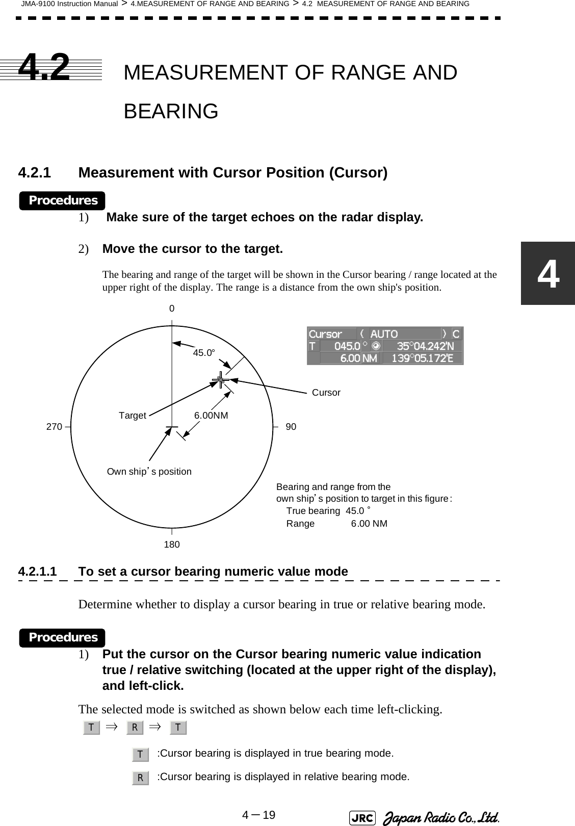
![4-20JMA-9100 Instruction Manual > 4.MEASUREMENT OF RANGE AND BEARING > 4.2 MEASUREMENT OF RANGE AND BEARING4.2.2 Measurement with Electronic Bearing Line and VariableRange Marker [EBL] [VRM] Procedures1) Press the [EBL1] key.The (located at the upper right of the display) will be highlighted, and EBL1 will be shown with a dotted line on the PPI display.2) Move the EBL1 to the target by turning the [EBL] dial.The EBL1 bearing will be shown in the EBL1 bearing (located at the upper right of the display). The EBL1 bearing is the bearing of the target.3) Press the [VRM1] key.The (located at the upper right of the display) will be highlighted, and VRM1 will be shown with a dotted line on the PPI display.4) Move the VRM1 to the target by turning the [VRM] dial.The range of VRM1 from the own ship's position will be shown in the VRM1 range located at the upper right of the display.EBL1 adjustmentVRM1 adjustmentEBL1 numeric value indication true / relative switchingEBL1 starting point mode switchingEBL1VRM1TargetEBL11800 90270VRM15.00NMBearing and range from theown ship’s position to target in this figure:True bearing 45.0 °Range 5.00 NM45.0°Own ship’s position](https://usermanual.wiki/Japan-Radio/NKE1130.Users-Manual-1/User-Guide-994629-Page-268.png)
![JMA-9100 Instruction Manual > 4.MEASUREMENT OF RANGE AND BEARING > 4.2 MEASUREMENT OF RANGE AND BEARING4-2144.2.3 Measurement with Two Arbitrary PointsProcedures1) Press the [EBL2] key.The ( located at the upper right of the display) will be highlighted, and EBL2 will be shown on the PPI display.2) Press the [EBL] dial to select C for the EBL2 starting point mode switching located at the upper right of the display.3) Put the cursor on the point A of the two points between which measurement is made, and left-click.Refer to the figure below.4) Move the EBL2 to the other point B by turning the [EBL] dial.5) Press the [VRM2] key.When VRM2 is selected, ● (intersection marker) will appear on the dotted line of EBL2.6) Move the intersection marker on the dotted line to point B by turning the [VRM] dial.The range and bearing between the two points will be shown in the VRM2 range and EBL2 bearing (located at the upper right of display).Similarly, EBL1 can also be used for measuring the bearing and range between two points. In this case, perform the above procedure reading EBL2 as EBL1 and VRM2 as VRM1.EBL2CapeEBL290.0°1800 90270VRM26.00NMBearing and range between pointsA and B in this figure:True bearing 90.0 °Range 6.00 NMCapeABOwn ship’s position](https://usermanual.wiki/Japan-Radio/NKE1130.Users-Manual-1/User-Guide-994629-Page-269.png)

![OPERATION OF TARGET TRACKING AND AIS5.1 PREPARATION ......................................................................................5-15.1.1 Collision Avoidance ........................................................................5-25.1.2 Definitions of Symbols ...................................................................5-55.1.3 Radar Display ..................................................................................5-85.1.4 Cursor Modes (Cursor) .................................................................5-105.1.5 Setting Collision Decision Criteria ..............................................5-125.1.6 Setting Vectors (Vector Time) ......................................................5-135.1.7 Setting the GPS antenna location ................................................5-135.2 TARGET TRACKING OPERATION .....................................................5-145.2.1 Acquiring Target [ACQ] ................................................................5-145.2.2 Canceling Unwanted Tracked Targets [ACQ CANCEL] .............5-165.2.3 Tracked Target Data Display [TGT DATA] ..................................5-175.2.4 Displaying Target ID No.(Target Number Display) .....................5-185.2.5 Adding Tracked Target ID Name (Name) .....................................5-195.2.6 Reference Target (Reference) ......................................................5-205.2.7 Operation Test (TT Test Menu) ...................................................5-215.3 AIS OPERATION ..................................................................................5-26SECTION 5OPERATION OF TARGET TRACKINGAND AIS](https://usermanual.wiki/Japan-Radio/NKE1130.Users-Manual-1/User-Guide-994629-Page-271.png)
![5.3.1 Restrictions ....................................................................................5-265.3.2 Setting AIS Display Function (AIS Function) ..............................5-265.3.3 Activate AIS Targets (Activate AIS) .............................................5-275.3.4 Deactivate AIS Targets (Deactivate AIS) .....................................5-275.3.5 Displaying AIS Information [TGT DATA] .....................................5-285.3.6 Displaying Target ID No. (Target Number Display) ....................5-315.3.7 Setting AIS Filter (AIS Filter Setting) ...........................................5-325.3.8 Conditions for Deciding AIS Target to be Lost ..........................5-355.3.9 Setting Conditions for AIS Alarm (AIS Alarm Setting) ...............5-365.4 DECISION OF TARGETS AS IDENTICAL (Association) ...................5-375.4.1 Setting of Function to Decide Targets as Identical (Association) .....5-375.4.2 Setting of Conditions for Deciding AIS and Tracked Targets as Identical (Association Setting) .....................................................5-375.4.3 Types of Decision Conditions to be Set ......................................5-385.5 ALARM DISPLAY .................................................................................5-395.5.1 CPA / TCPA Alarm .........................................................................5-405.5.2 Alarm for New Target Acquired in Automatic Acquisition Zone (New Target) ...................................................................................5-415.5.3 Lost Target Alarm (Lost) ...............................................................5-415.5.4 Gyro Set Alarm ..............................................................................5-425.6 TRACK FUNCTION ..............................................................................5-435.6.1 Past Position (Past POSN) ...........................................................5-435.6.2 Target Ship's Tracks (Target Track) ............................................5-445.7 TRIAL MANEUVERING (Trial Maneuver) ..........................5-535.7.1 Trial Maneuvering in the True Vector Mode ................................5-545.7.2 Trial Maneuvering in the Relative Vector Mode ..........................5-555.7.3 Operation of Trial Maneuvering Function ...................................5-56](https://usermanual.wiki/Japan-Radio/NKE1130.Users-Manual-1/User-Guide-994629-Page-272.png)
![JMA-9100 Instruction Manual > 5.OPERATION OF TARGET TRACKING AND AIS > 5.1 PREPARATION5-155.1 PREPARATION This section explains the features of the target tracking and AIS functions, and the initial setting for using each function.Target Tracking FunctionThe target tracking function calculates the course and speed of a target by automatically tracking the target's move. The target tracking function enables the automatic acquisition of targets by using the automatic acquisition zone function. The target tracking function also enables the simulation of the ship maneuvering method to avoid collisions by using the trial maneuver function.•There are the following limitations on use of the target acquisition and target tracking functions.[I] Resolution between adjacent targets and swapping during automatic target trackingDepending on the particular distance and echo size, resolution between adjacent targets during automatic target tracking usually ranges somewhere between 0.03 to 0.05 NM. If multiple targets approach each other, resolution will become about 0.05 NM and this may cause the system to regard them as one target and thus to swap them or lose part of them. Such swapping or less of targets may also occur if the picture of the target being tracked is affected by rain/snow clutter returns or sea clutter returns or moves very close to land.[II] Intensity of echoes and the target tracking functionThe intensity of echoes and the tracking function have a correlationship, and thus the target will be lost if no echoes are detected during six scans in succession. If a lost target exists, therefore, radar gain must be increased to support detection of the target. If, however, radar gain is increased too significantly, sea clutter returns or other noise may be erroneously detected and tracked as a target, and resultingly, a false alarm may be issued.[III]Adverse effects of error sources on automatic trackingTo execute accurate tracking, it becomes necessary first to appropriately adjust the [GAIN], [SEA] and [RAIN] dials of the radar so that the target to be acquired and tracked id clearly displayed on the radar display. Inappropriate settings of these adjustments reduce the reliability / accuracy of automatic tracking.Attention](https://usermanual.wiki/Japan-Radio/NKE1130.Users-Manual-1/User-Guide-994629-Page-273.png)
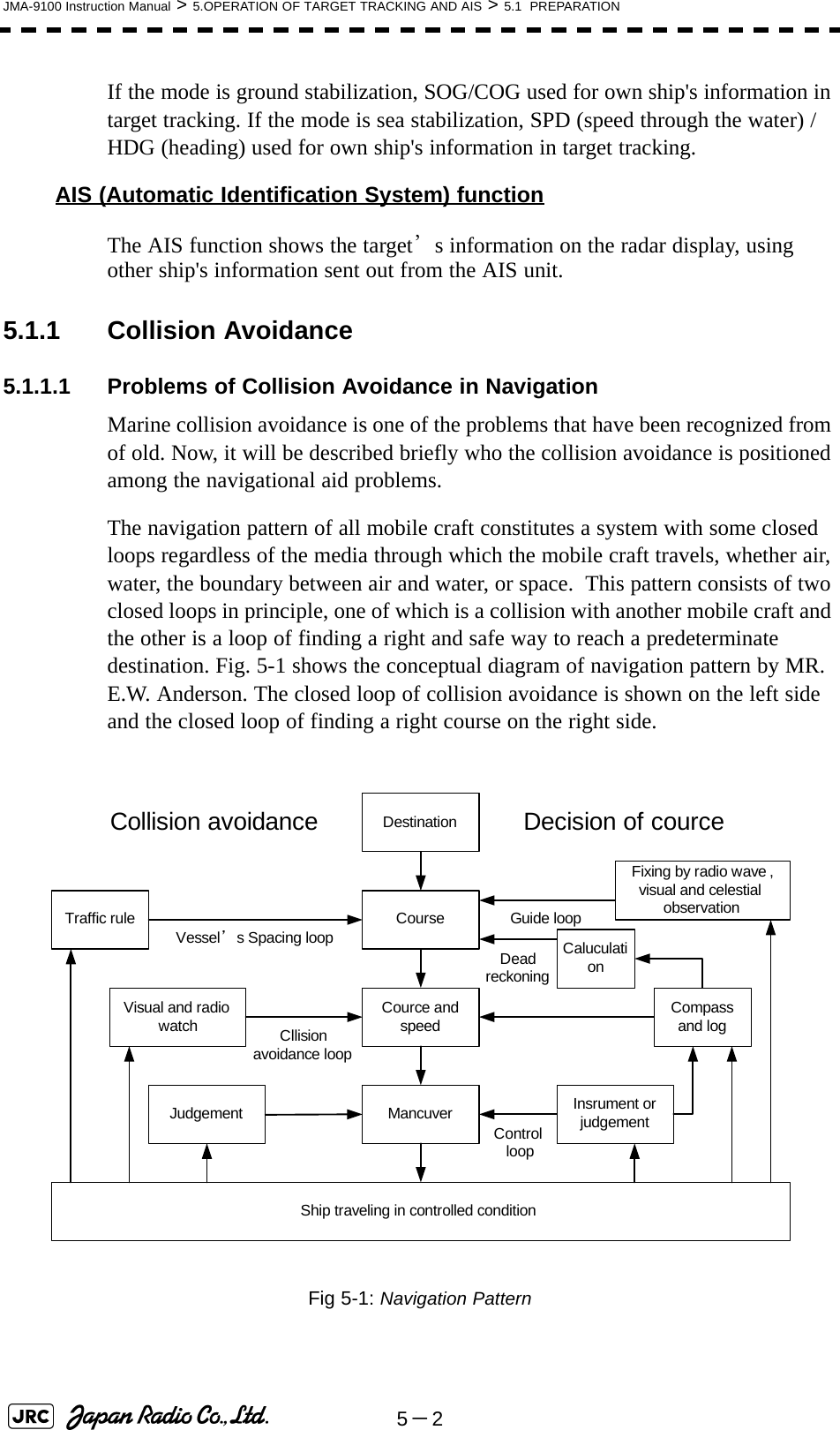
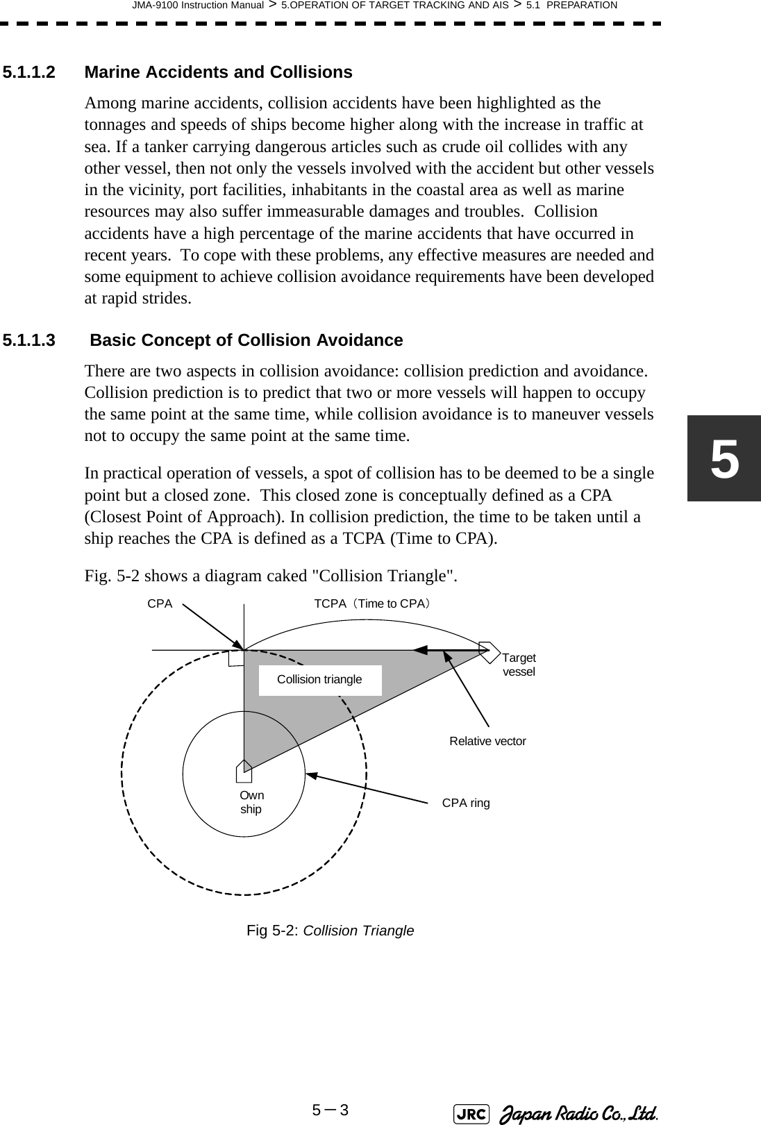
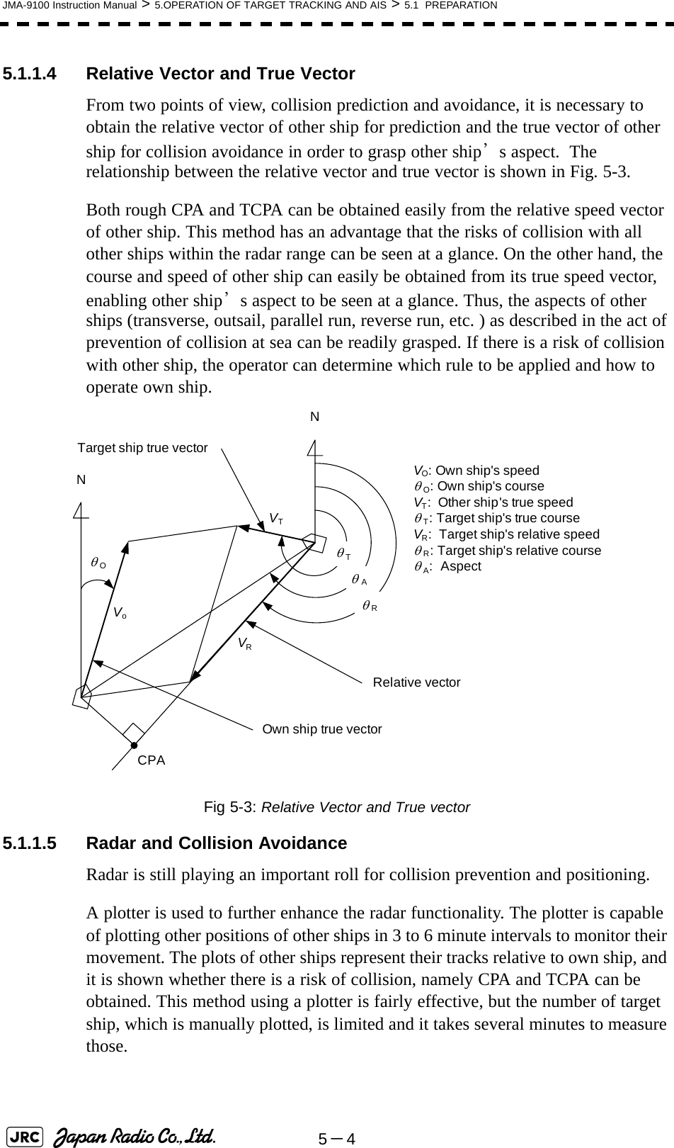
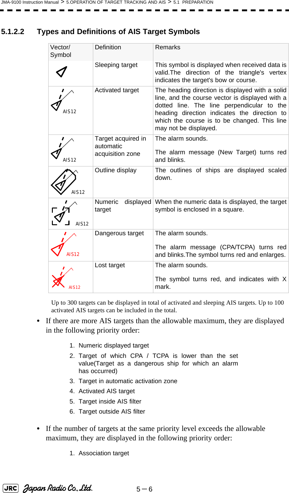
![5-8JMA-9100 Instruction Manual > 5.OPERATION OF TARGET TRACKING AND AIS > 5.1 PREPARATIONb. Setting of AIS Target Symbol DisplayThis function switches the AIS target symbol display between on and off.Procedures1) Left-click the button in the Target Information located at the upper right of the display.The AIS target symbol display will be set to on or off.5.1.3 Radar Display5.1.3.1 Vector DisplayA vector to represent a target’s predicted position can be presented in the True vector or Relative vector mode. In each mode, a vector length can be freely changed for a time interval of 1 to 60 minutes.To switch between the true vector mode and relative vector mode, press the [T/R VECT] key.5.1.3.2 Vector Mode Selection[1] True Vector ModeIn the true vector mode, the direction of a target vector indicates the true course of the target and its vector length is proportional to its speed.In this mode, own ship's vector is displayed as shown Fig 5-4.In this mode, the movements of other ships around own ship can be accurately and easily monitored.However, CPA Ring cannot appear in this mode.Fig 5-4: True Vector The relative vector isnot displayedTrue vectorOwn ship’s position HL](https://usermanual.wiki/Japan-Radio/NKE1130.Users-Manual-1/User-Guide-994629-Page-280.png)