Japan Radio NKE1130 Marine Radar User Manual JMA 9100 series RADAR Instruction Manual
Japan Radio Co Ltd. Marine Radar JMA 9100 series RADAR Instruction Manual
Contents
- 1. Users Manual 1
- 2. Users Manual 2
- 3. Users Manual 3
- 4. Users Manual
Users Manual 3
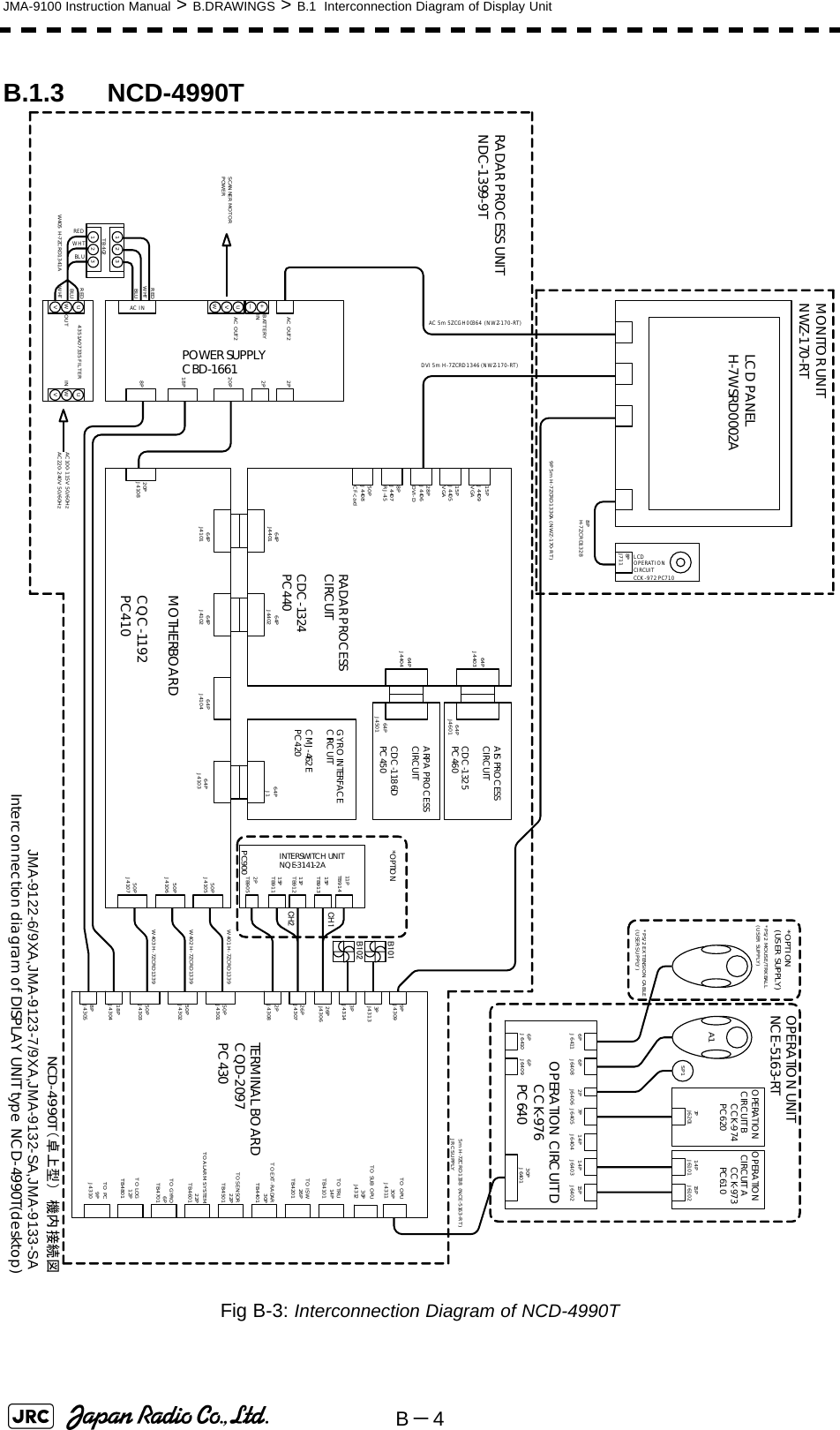
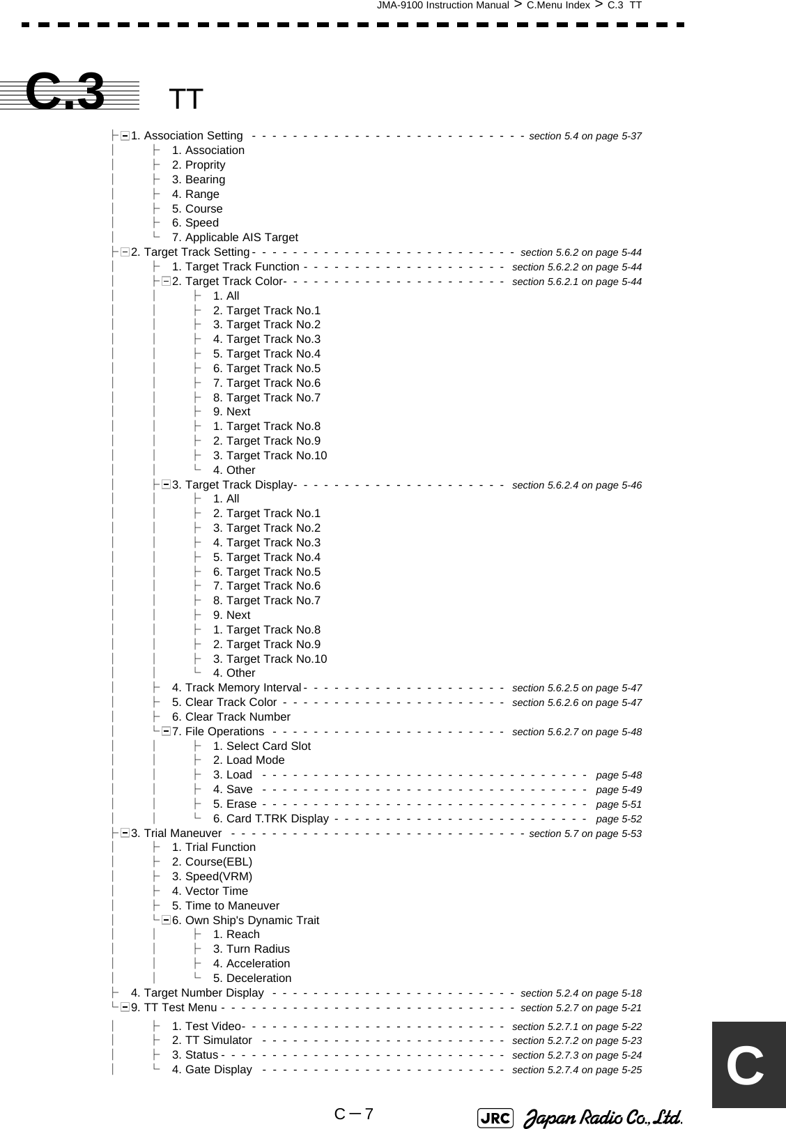
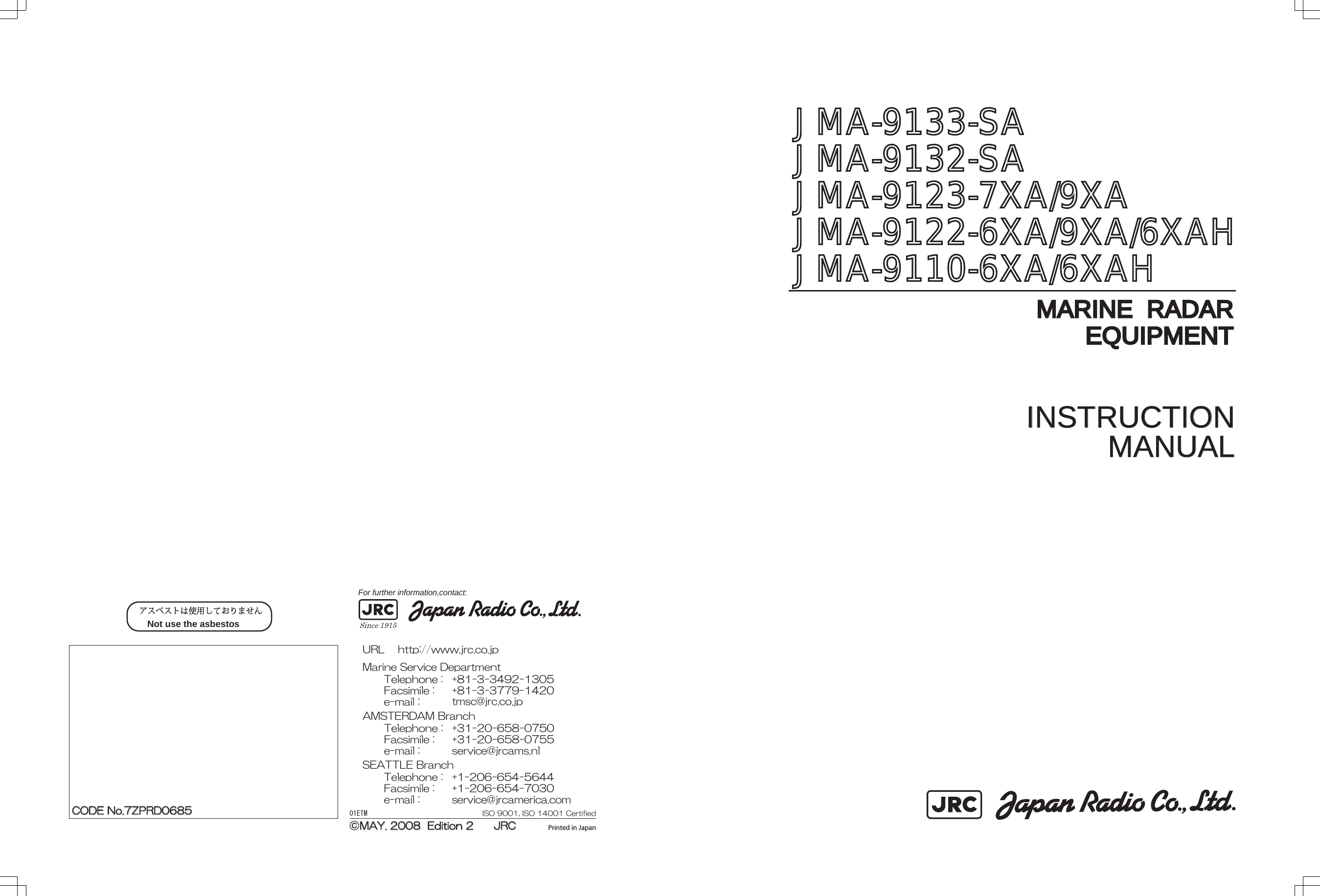
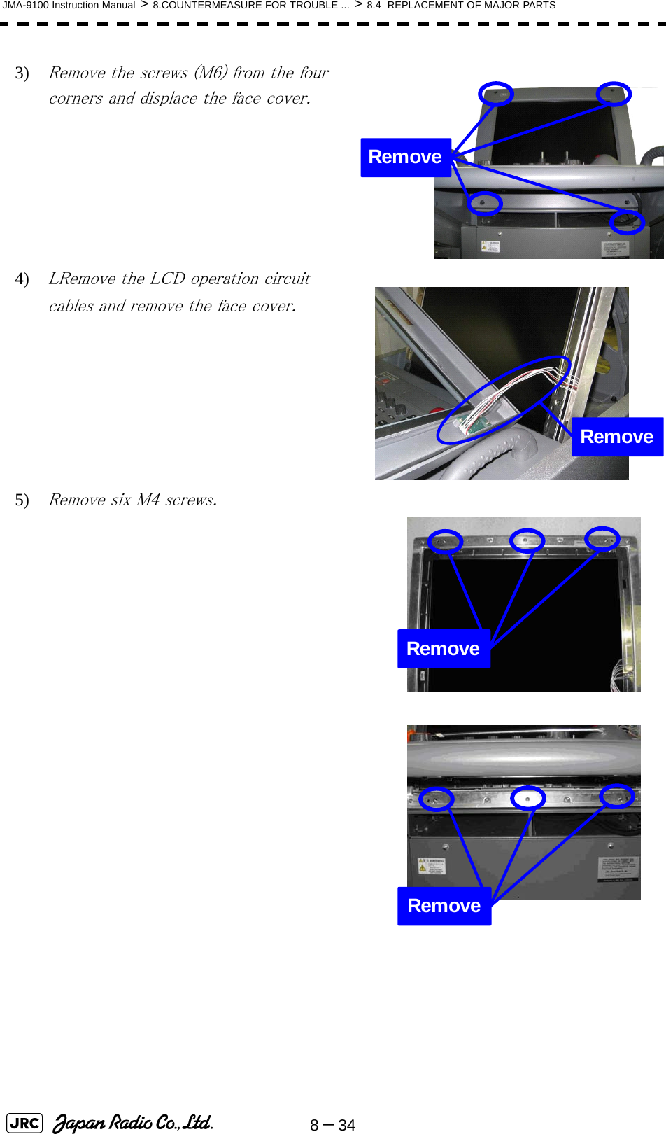
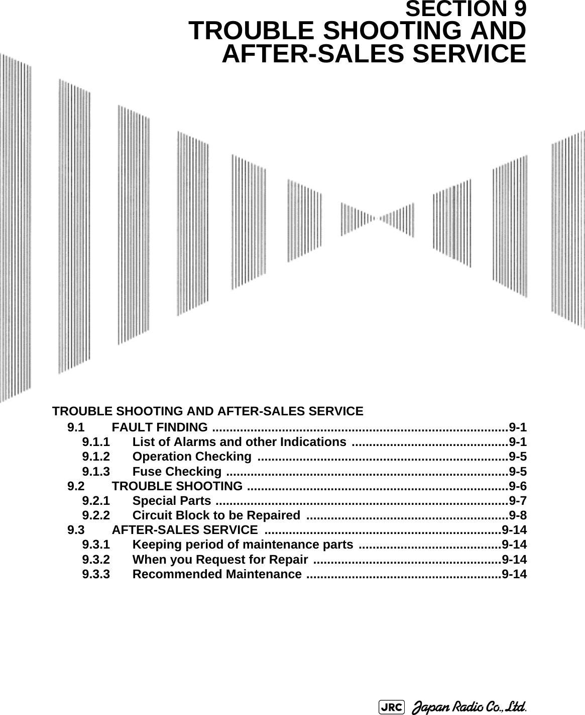
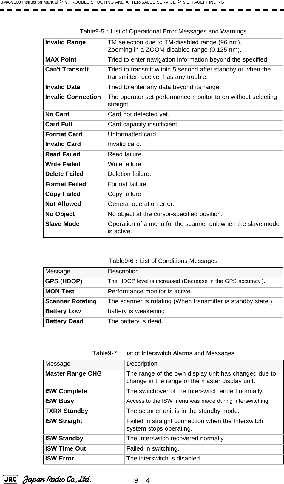
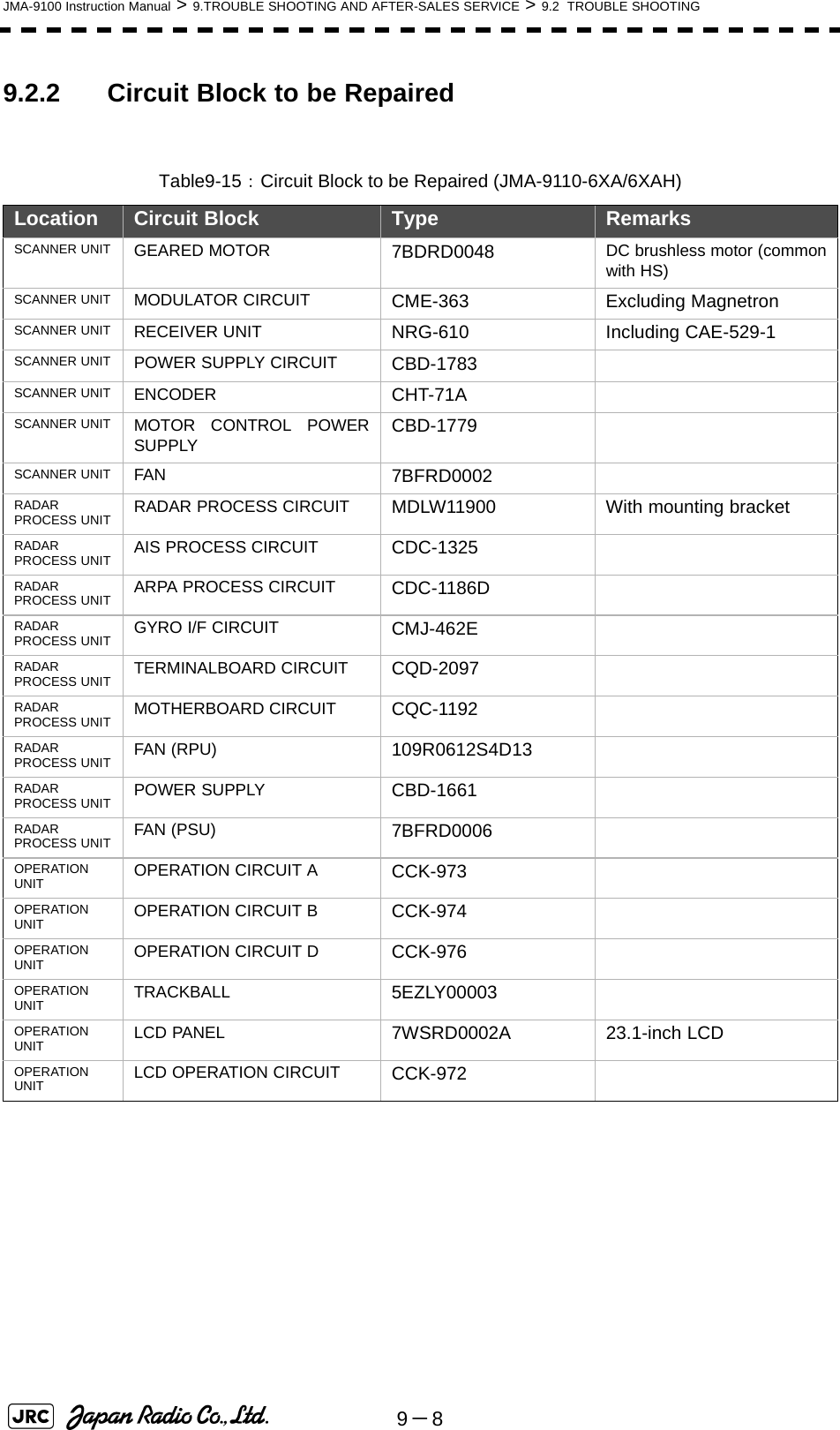
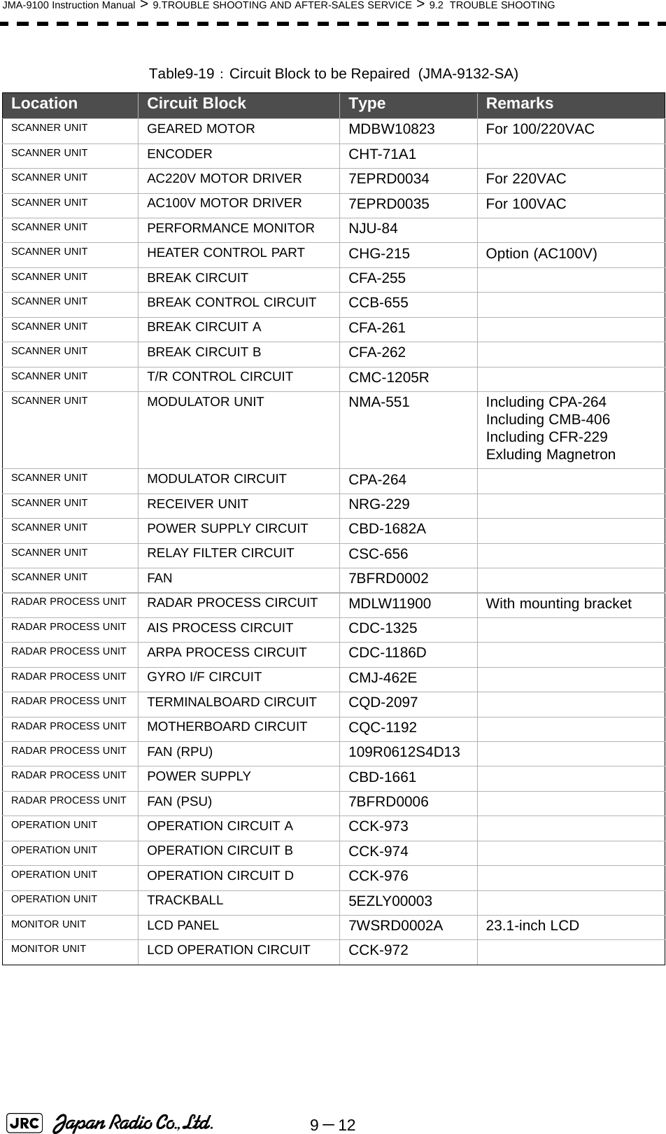
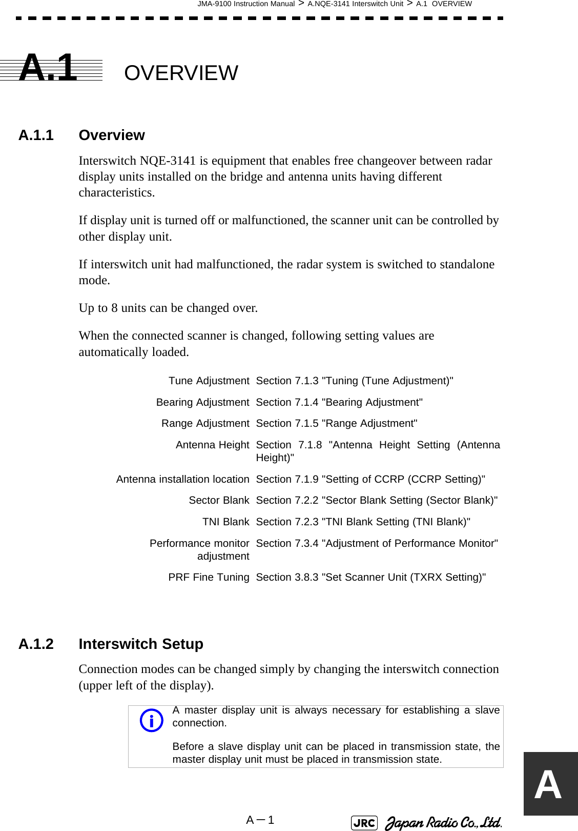
![JMA-9100 Instruction Manual > 8.COUNTERMEASURE FOR TROUBLE ... > 8.4 REPLACEMENT OF MAJOR PARTS8-3388.4.4 Replacement of LCD Monitor8.4.4.1 Display Unit NCD-4990Do not touch the LCD screen directly with your fingers.Do not touch the AR filter directly with your fingers.Perform the replacement work on a soft cloth to avoid damage to the LCD screen and other parts.[Required tools]•A Phillips screwdriver for 4 mm screws•A Phillips screwdriver for 6 mm screws[Disassembly]1) Remove the tilt fixing handle (standalone type only).2) Tilt up the screen as much as you can (standalone type only).Replacement of LCD monitor must be made by specializedservice personnel. For details, refer to Service Manual.](https://usermanual.wiki/Japan-Radio/NKE1130.Users-Manual-3/User-Guide-994639-Page-1.png)
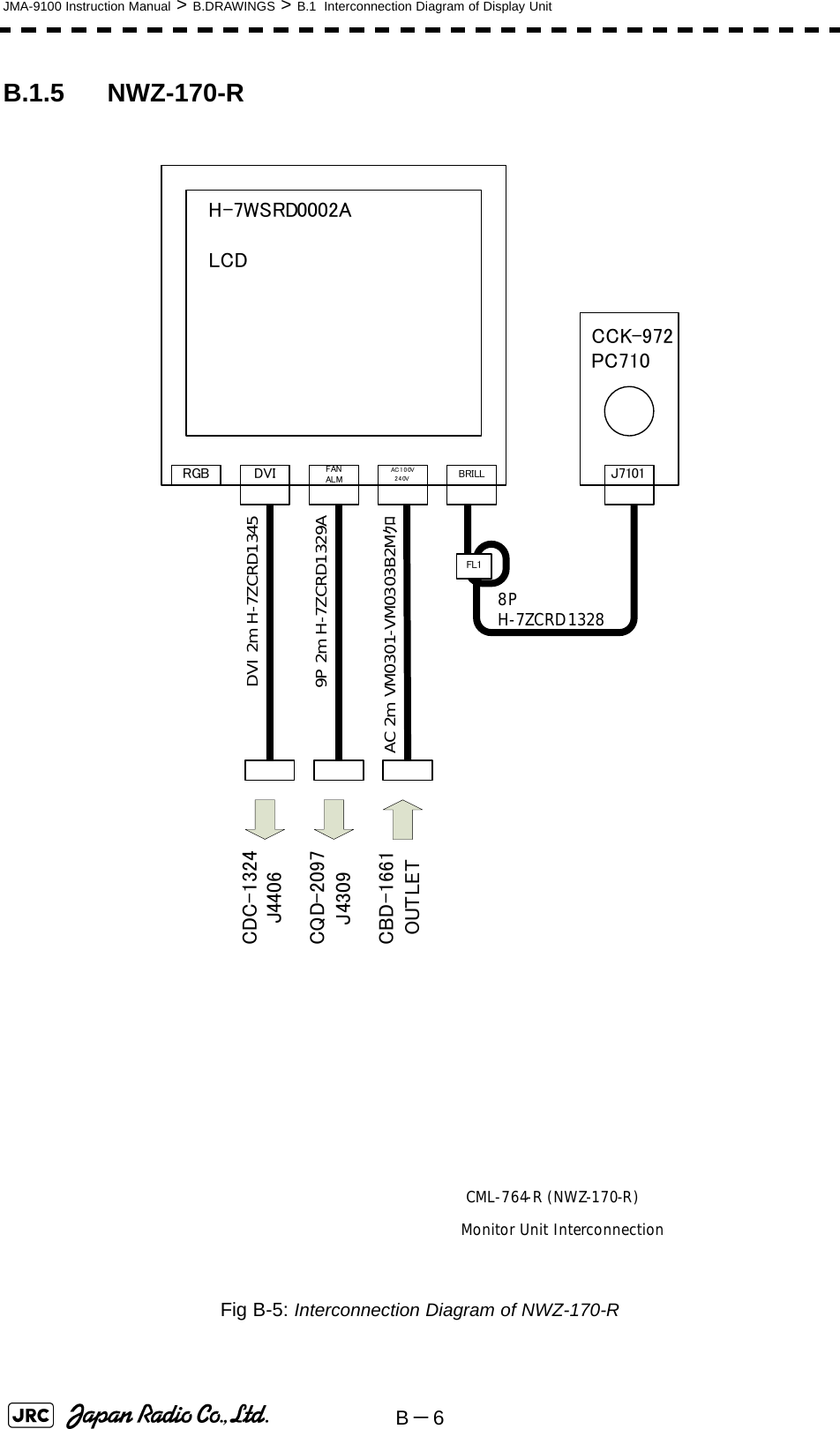
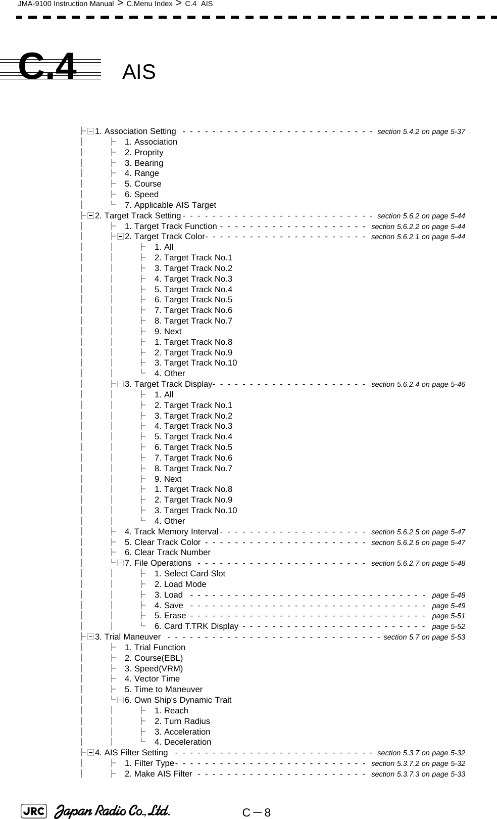
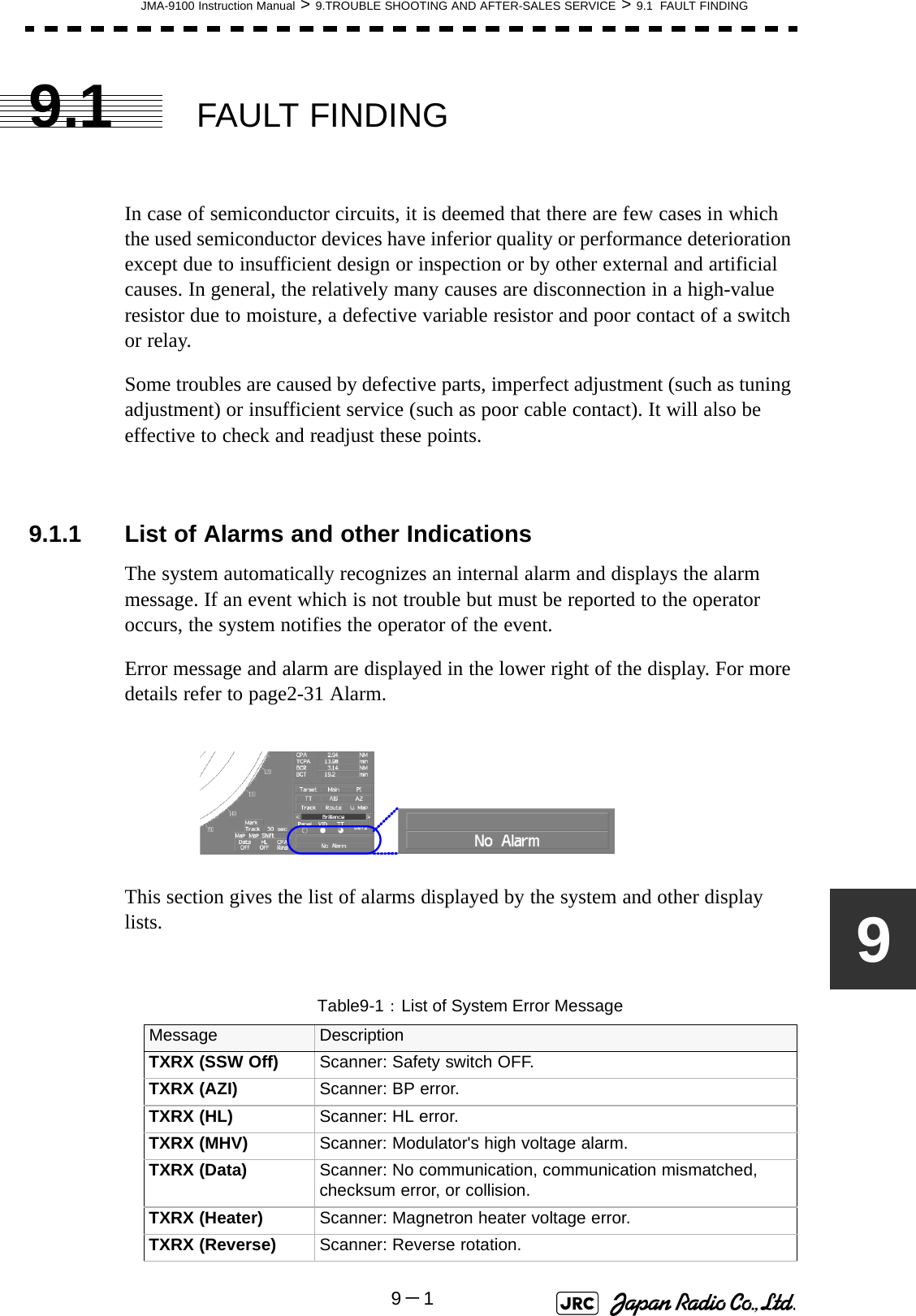
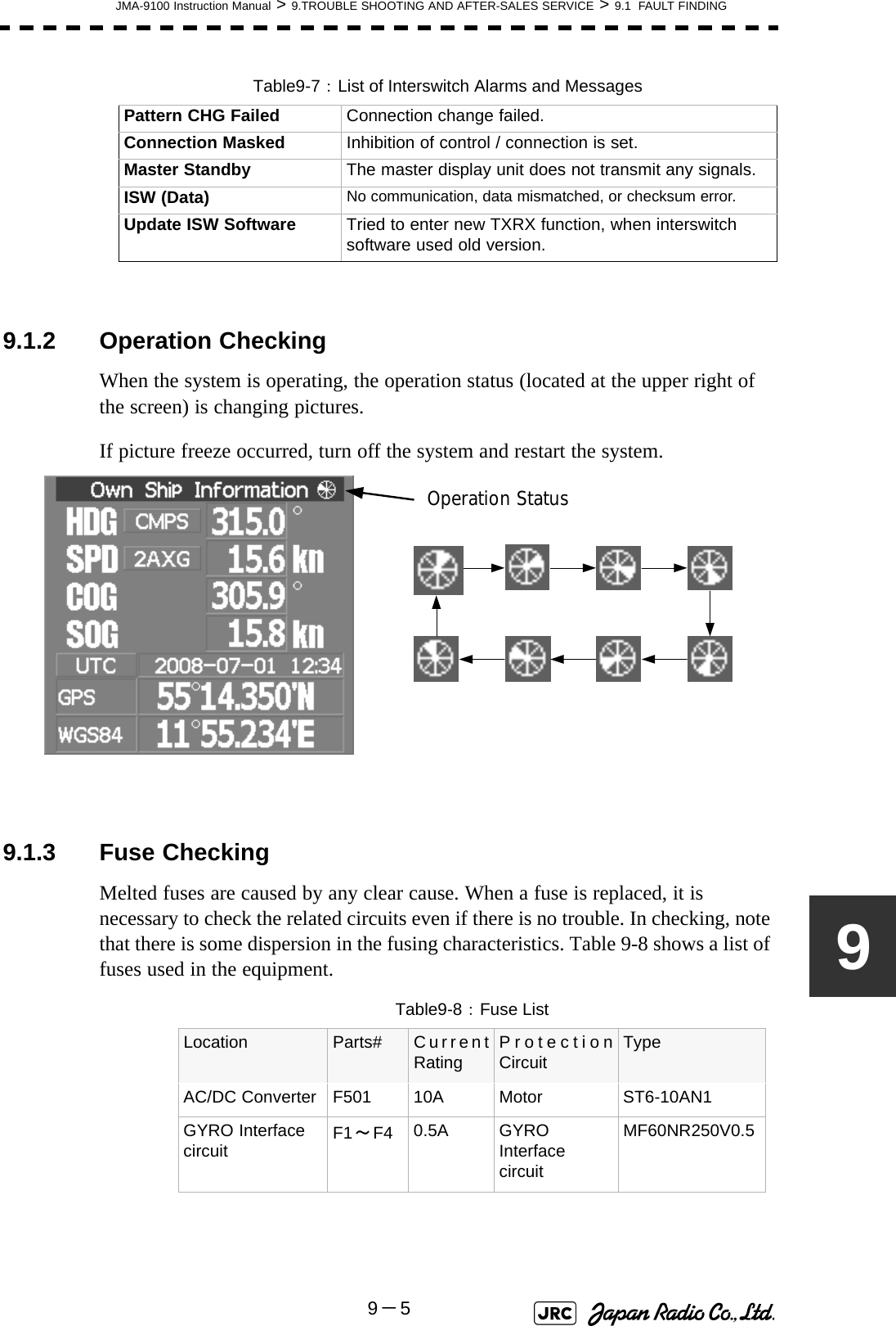
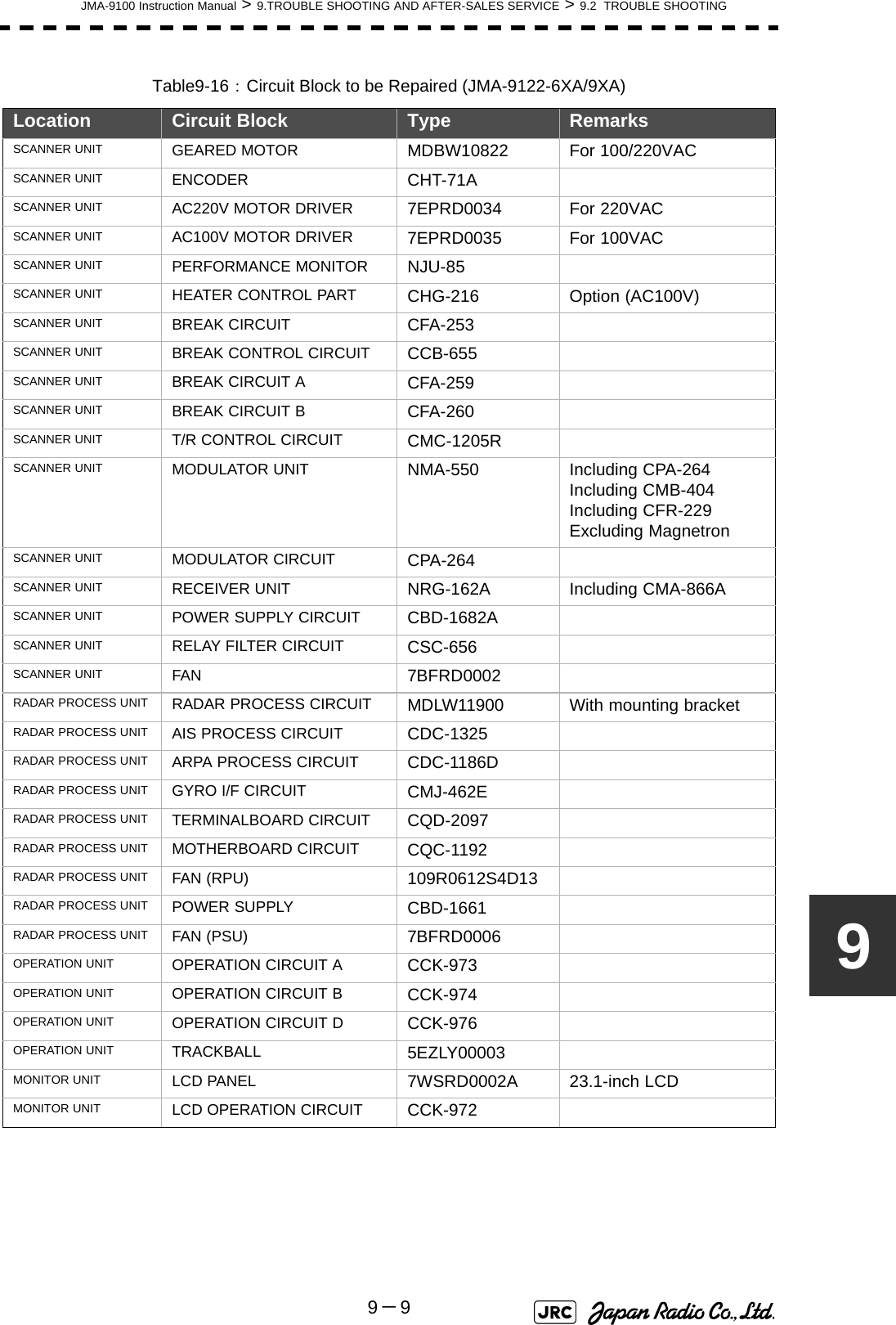
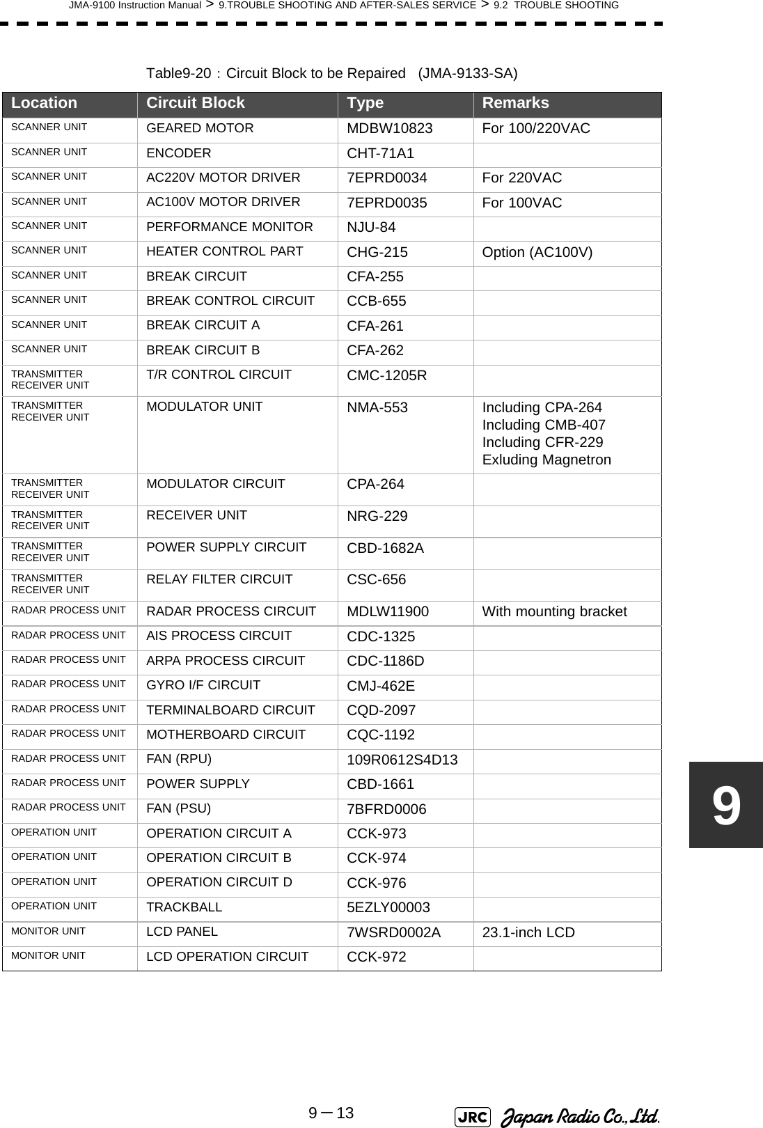
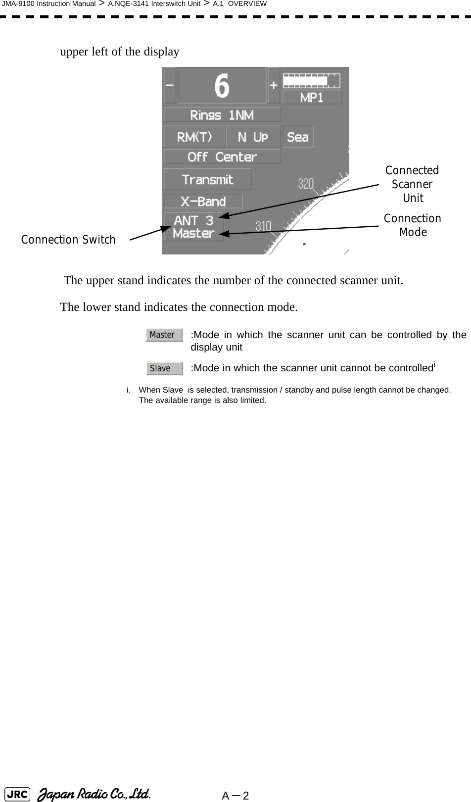
![JMA-9100 Instruction Manual > 8.COUNTERMEASURE FOR TROUBLE ... > 8.4 REPLACEMENT OF MAJOR PARTS8-3586) Displace the module and remove the three cables.7) Remove the LCD module.[Assembly]1) Tighten the lower three M4 screws halfway.2) Connect the cables to the LCD module.3) Align the module to the lower three screws and insert it downward.4) Check the positions of the two bosses and ensure that appropriate space is maintained under the LCD module. Tighten the six screws evenly.5) Connect the LCD operation circuit cables and attach the face cover.6) Tighten the screws at the four corners.7) Attach the tilt fixing handle.[Operation Check]1) After completing the replacement procedures, start the system to make sure that images are displayed properly.2) Turn the brightness knob to make sure the brightness can be changed between the minimum and the maximum levels. RemoveTemporary tightening Positions of the two bosses](https://usermanual.wiki/Japan-Radio/NKE1130.Users-Manual-3/User-Guide-994639-Page-3.png)
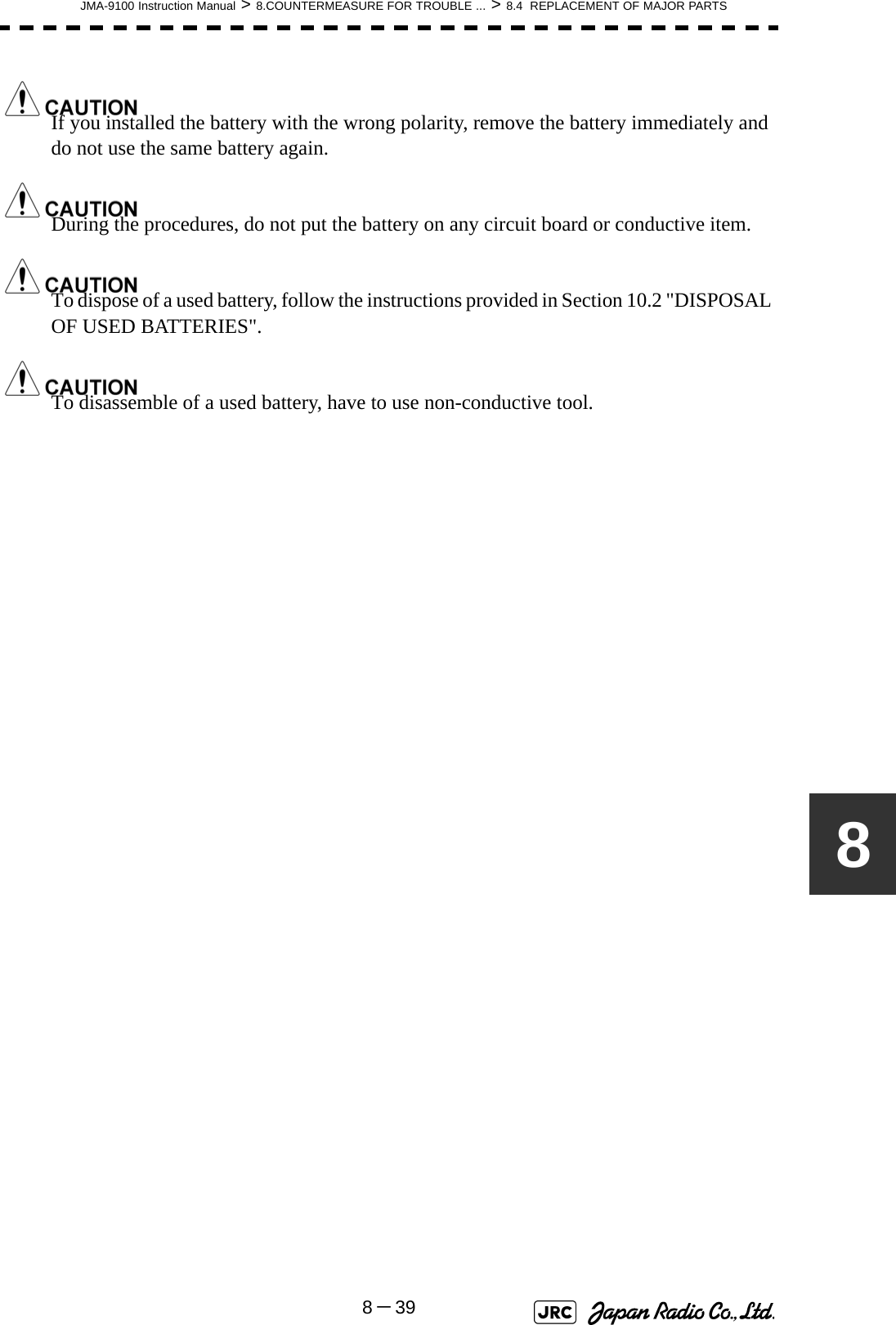
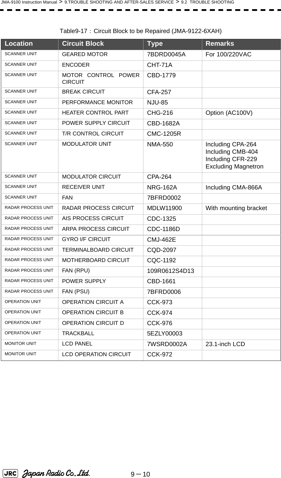
![8-36JMA-9100 Instruction Manual > 8.COUNTERMEASURE FOR TROUBLE ... > 8.4 REPLACEMENT OF MAJOR PARTS8.4.5 Replacement of Backup BatteryA coin-cell battery maintains radar system configuration, date, and time information while power off condition. Radar system configuration is saving to non-volatile memory at fixed intervals.8.4.5.1 About the Battery AlarmIf is appeared at the lower-right of the display when start up the radar system, the battery has not enough time left to live. We recommend to replace the battery.If is appeared at the lower-right of the display when start up the radar system, the battery has no time left to live. There is a necessary to replace the battery. In This condition, this radar system is restored configuration information from flash memory and normal operation is available. However, you turned of the radar system before saving to flash memory, the configuration information is maybe lost. In this case, you must setup the configuration again.8.4.5.2 How to Replacement of Backup Battery[Required tools]•A flat tip screwdriver for 6 mm screws•A Phillips screwdriver for 4 mm screws•A flat tip nonconductive screwdriver for 3 mm screwsReplacement of backup battery must be made by specializedservice personnel. For details, refer to Service Manual.About disposal of used battery, refer to Section 10.2.Battery LowBattery Dead](https://usermanual.wiki/Japan-Radio/NKE1130.Users-Manual-3/User-Guide-994639-Page-4.png)
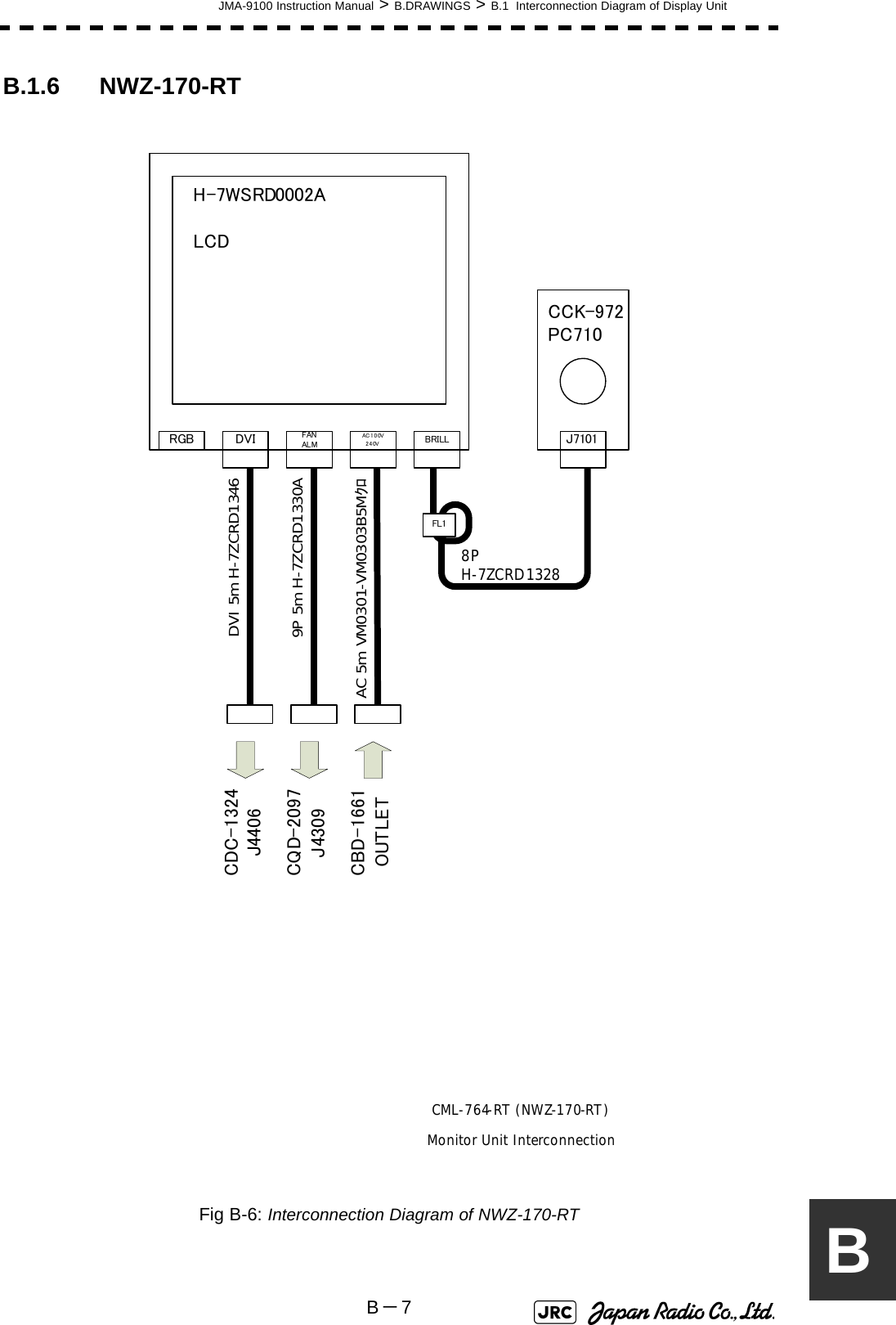
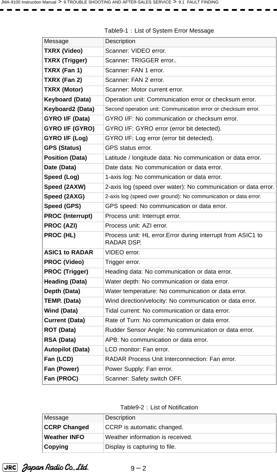
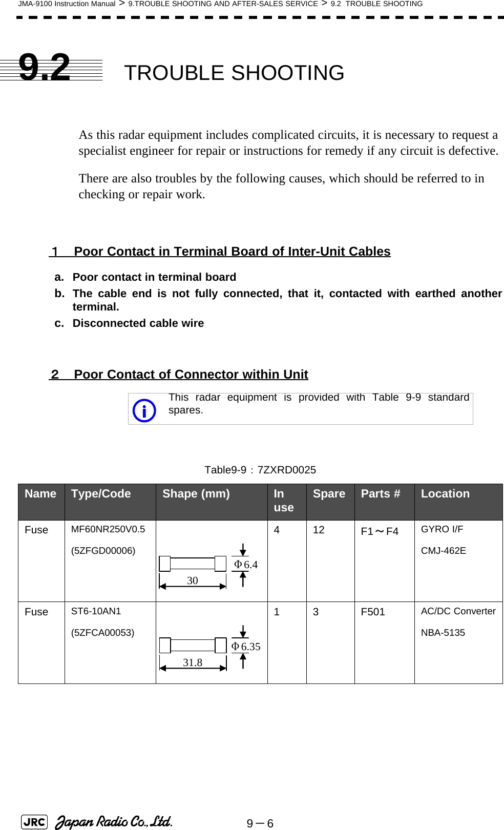
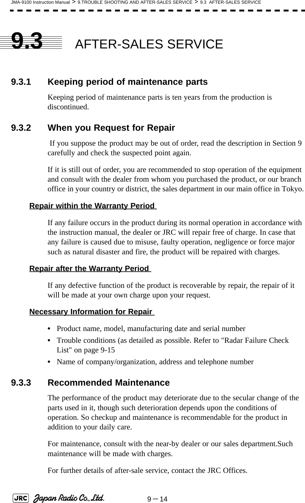
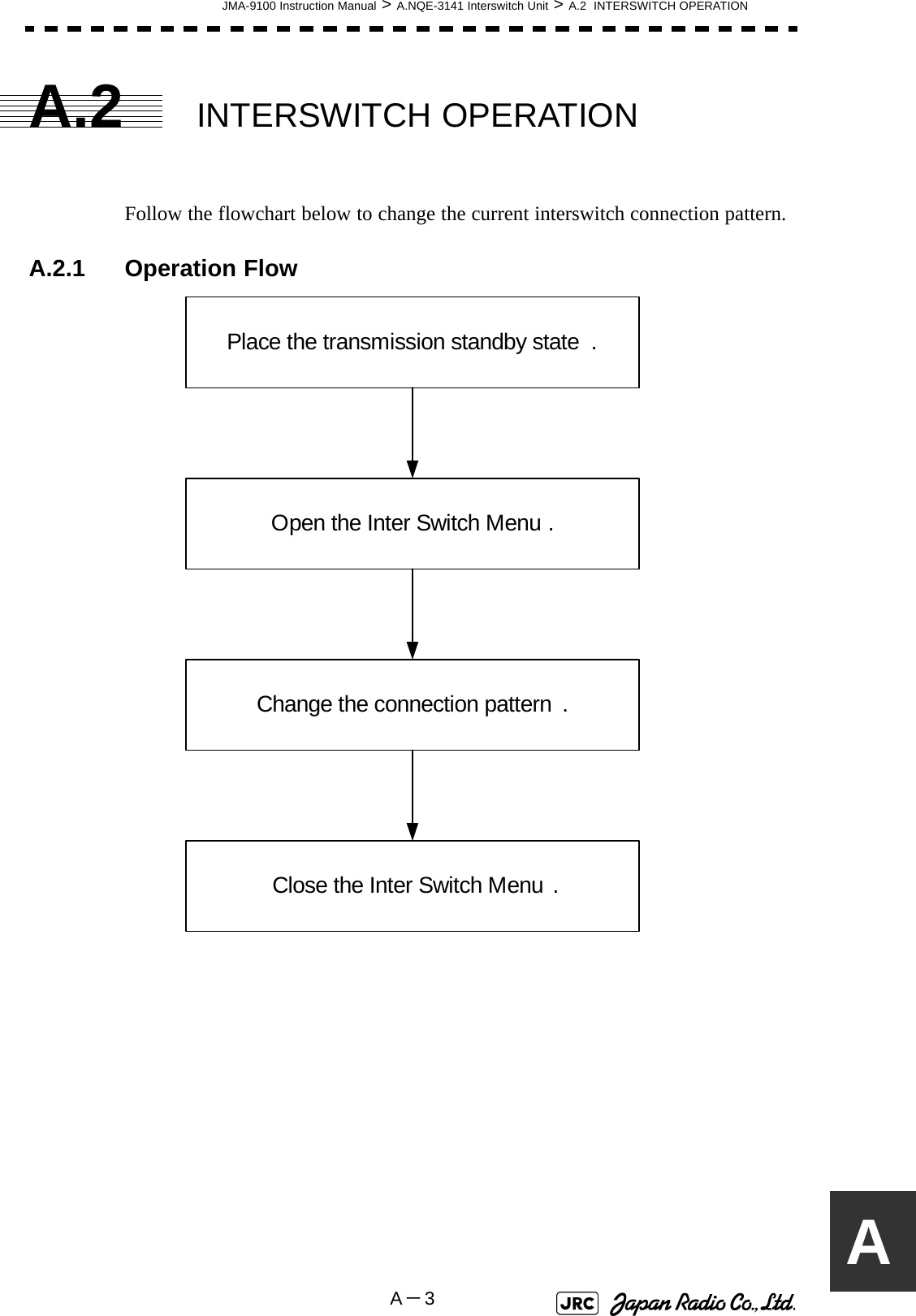
![JMA-9100 Instruction Manual > 8.COUNTERMEASURE FOR TROUBLE ... > 8.4 REPLACEMENT OF MAJOR PARTS8-378[Disassembly]1) Remove the four fixing screws to remove the cover from the display unit (NCD-4990).(A flat tip screwdriver for 6 mm screws)For standalone type NCD-4990For tabletop type: NDC-1399-92) Remove the cable connected to the radar processing circuit board.The radar processing circuit is the first board from the left.3) Remove the two fixing screws (M4).4) Pull out the board to the front.5) Insert the flat tip nonconductive screwdriver for adjustment or some stick between the battery and the battery holder and lift the battery up.RemoveRemoveRemove](https://usermanual.wiki/Japan-Radio/NKE1130.Users-Manual-3/User-Guide-994639-Page-5.png)
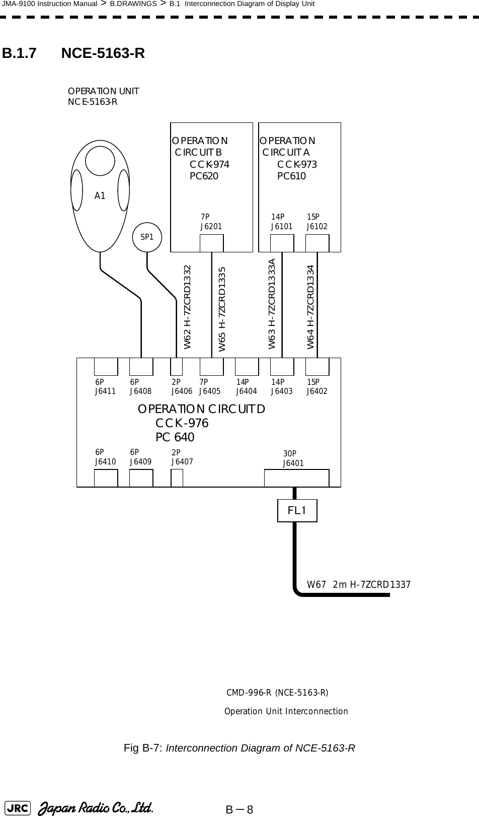
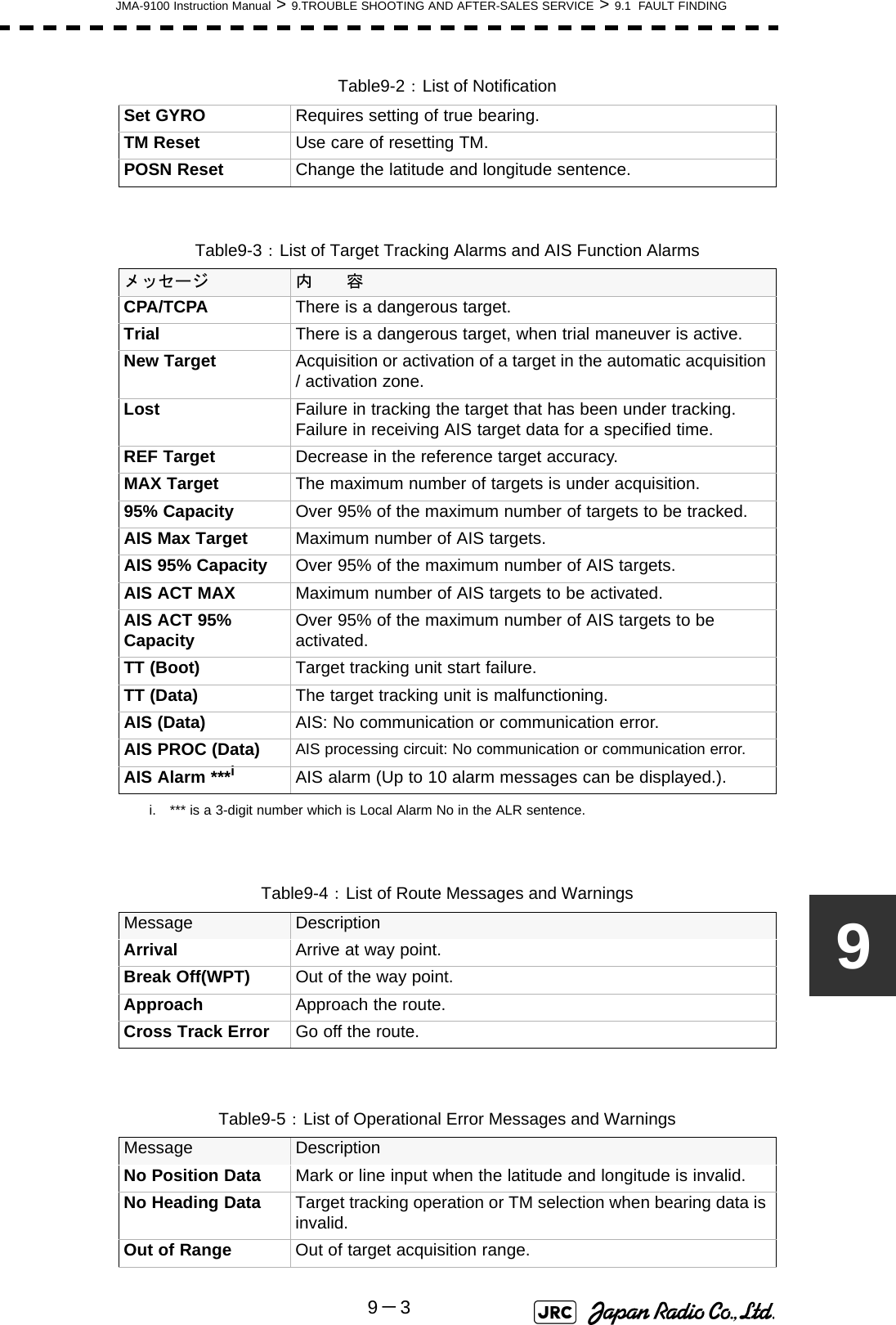
![8-38JMA-9100 Instruction Manual > 8.COUNTERMEASURE FOR TROUBLE ... > 8.4 REPLACEMENT OF MAJOR PARTS6) Insert the flat tip nonconductive sscrewdriver for adjustment or some stick to the location shown in the figure below and slide the battery sideways to remove the battery. [Assembly]1) Check the polarity of the battery. Make sure that the battery's positive (+) side is facing up.2) Slide the battery sideways into the battery holder.3) Make sure that the battery is inserted fully.[Check Item]1) Check that no error message comes up.2) Check that the system starts up normally.[Notes]](https://usermanual.wiki/Japan-Radio/NKE1130.Users-Manual-3/User-Guide-994639-Page-6.png)

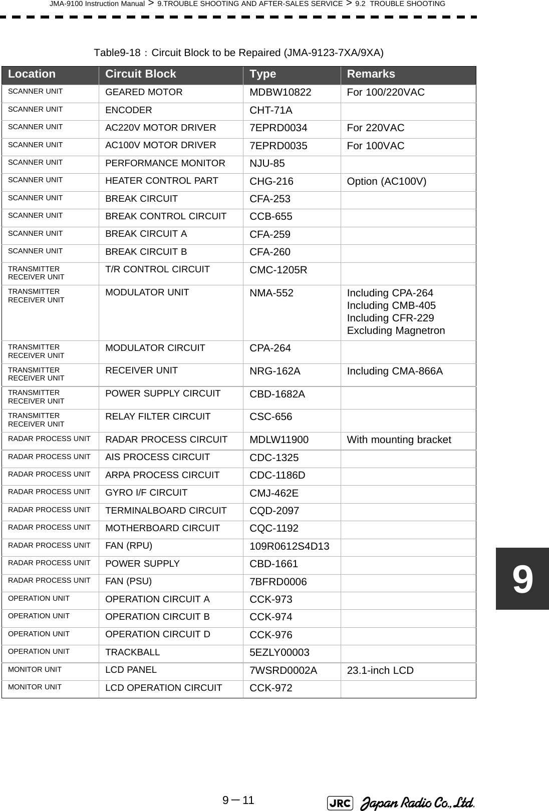
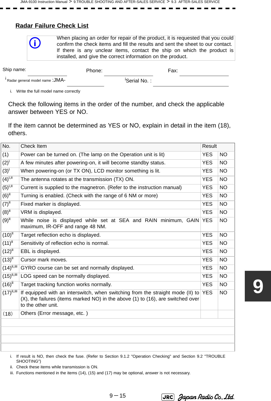


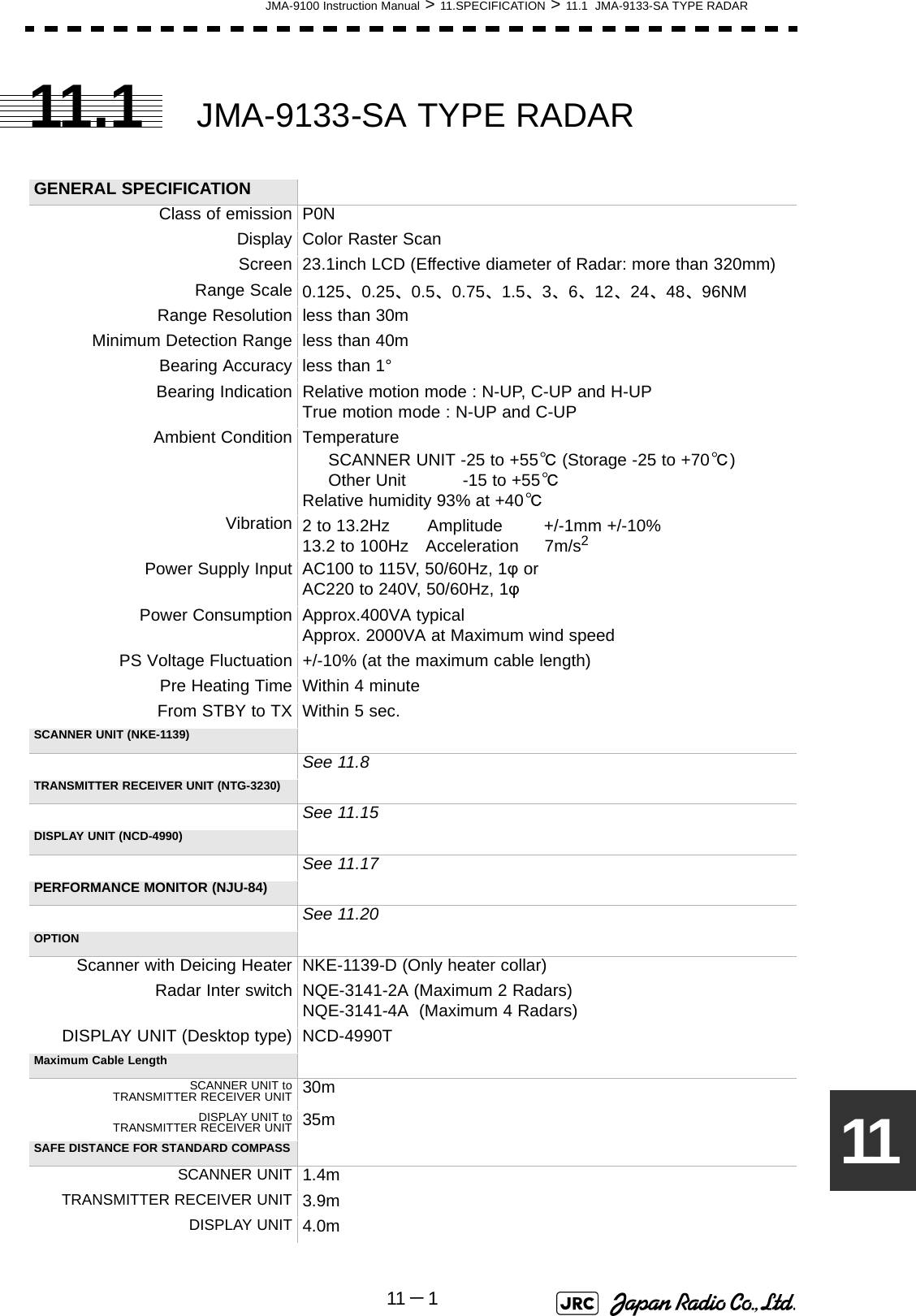
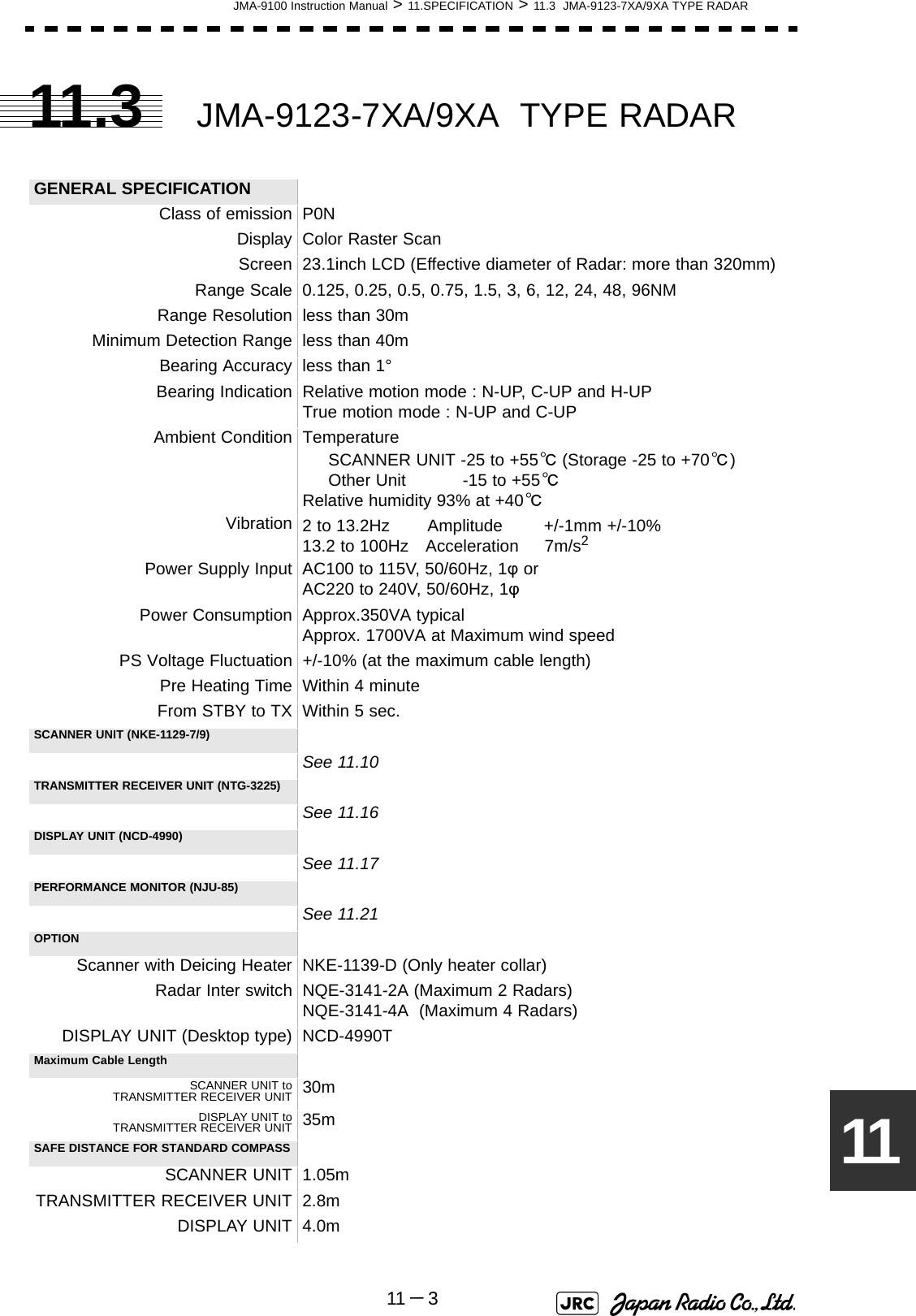


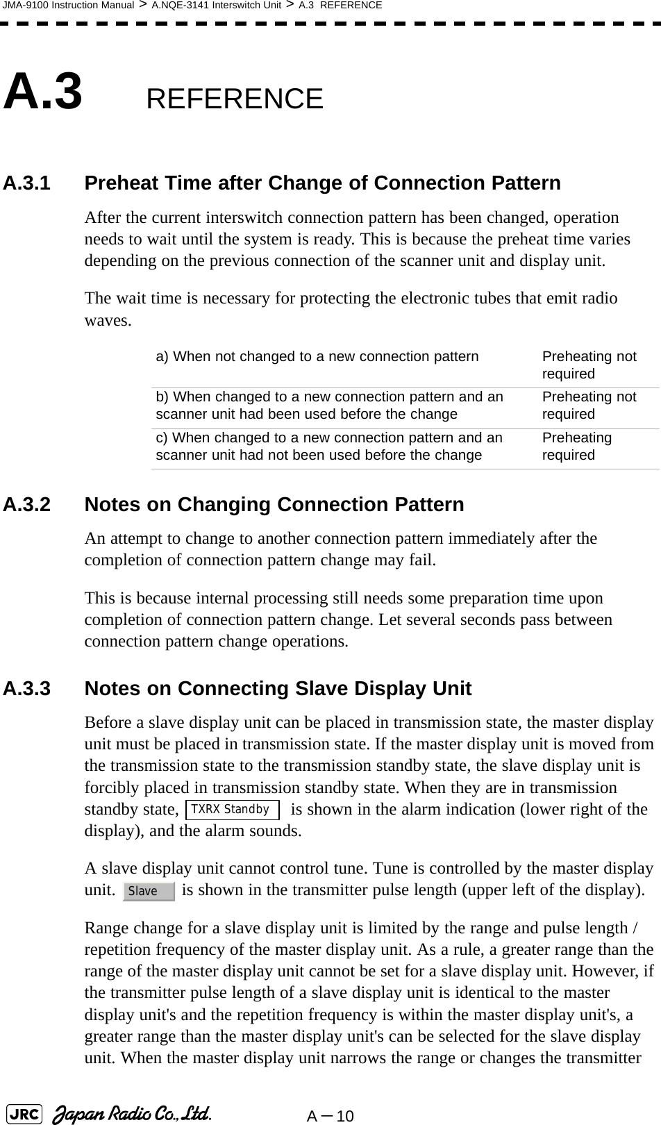
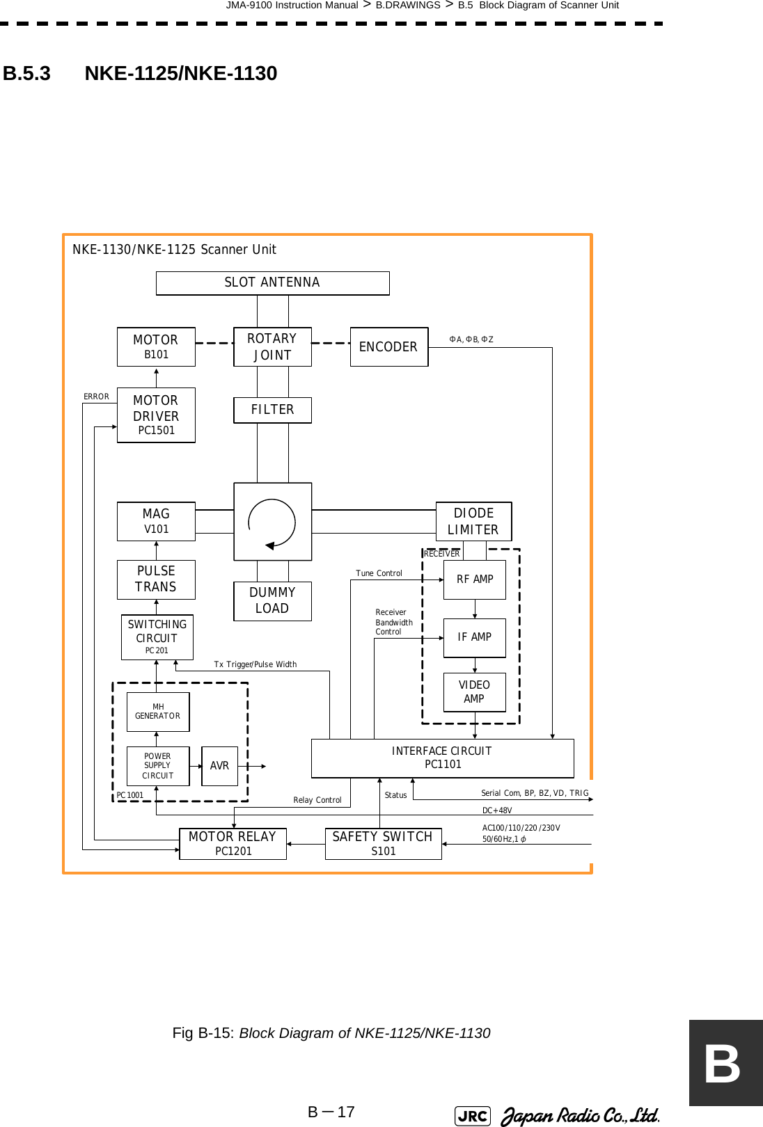
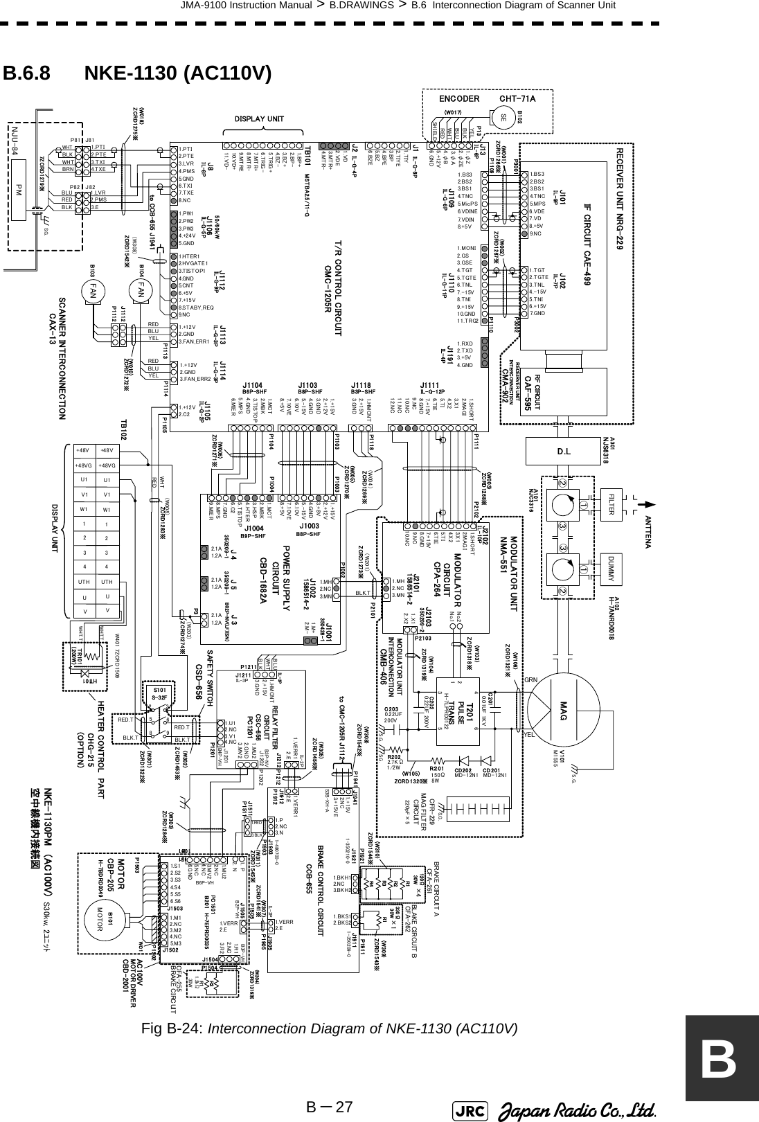
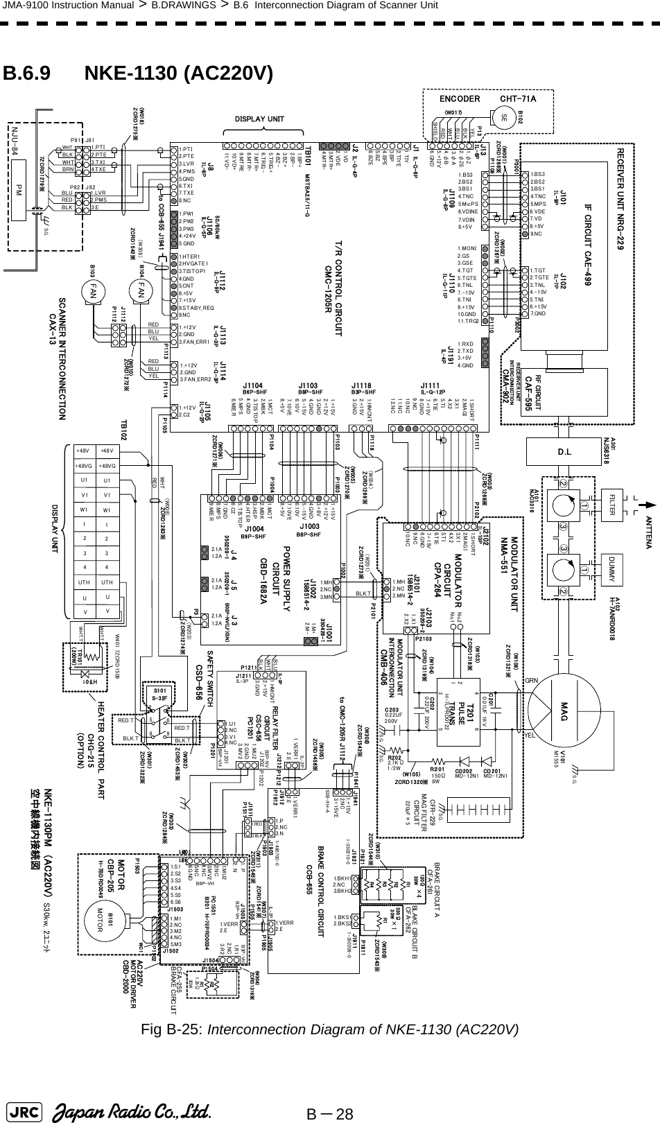
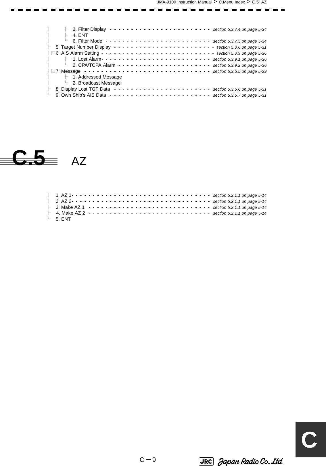
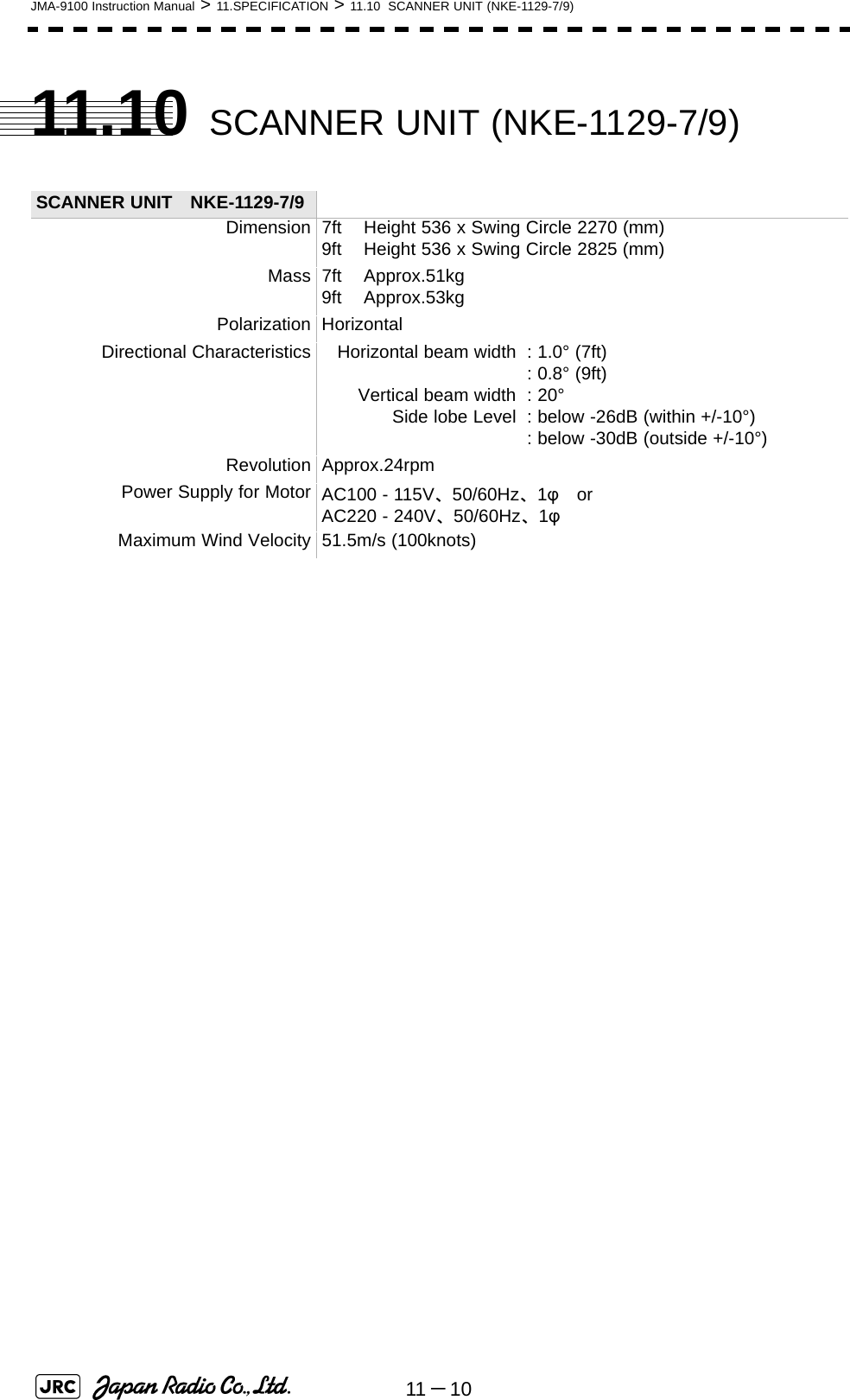
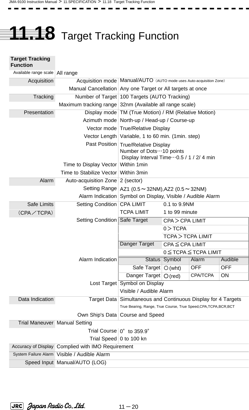
![JMA-9100 Instruction Manual > 11.SPECIFICATION > 11.9 SCANNER UNIT (NKE-1130)11 -91111.9 SCANNER UNIT (NKE-1130) SCANNER UNIT NKE-1130Dimension Height 791 x Swing Circle 4000 (mm)Mass Approx.180kgPolarization HorizontalDirectional Characteristics Horizontal beam widthVertical beam widthSide lobe Level: 1.9°: 25°: below -26dB (within +/-10°): below -30dB (outside +/-10°)Revolution Approx.24rpmPower Supply for Motor AC100 - 115V、50/60Hz、1φ orAC220 - 240V、50/60Hz、1φMaximum Wind Velocity 51.5m/s (100knots)Transmitting Frequency 3050±20MHzTransmitting Power 30kWTransmitting Tube Magnetron[M1555]TX Pulse width / RepetitionFrequency SP1:0.07μs/2250HzMP1:0.2μs/2250Hz MP2:0.3μs/1900Hz、MP3:0.4μs/1400Hz LP1:0.8μs/750Hz、LP2:1.0μs/650Hz LP3:1.2μs/510Hz0.125、0.25、0.5NM :SP1 0.75NM :SP1/MP1 1.5NM :SP1/MP1/MP2/MP3 3NM :MP1/MP2/MP3/LP1 6NM :MP1/MP2/MP3/LP1/LP2 12NM :MP1/MP2/MP3/LP1/LP2 24NM :MP3/LP1/LP2 48NM :LP2 96NM :LP3Modulator Solid State Modulator CircuitDuplexer Circulator + Diode LimiterFront End Module Built-inIntermediate Frequency Amplifier Intermediate FrequencyBand WidthGainAmplifying Characteristics: 60MHz: 25/8/3MHz: more than 90dB: Logarithmic AmplifierOverall Noise Figure 7.5dB ( Typical)Tuning Manual/AUTO](https://usermanual.wiki/Japan-Radio/NKE1130.Users-Manual-3/User-Guide-994639-Page-43.png)
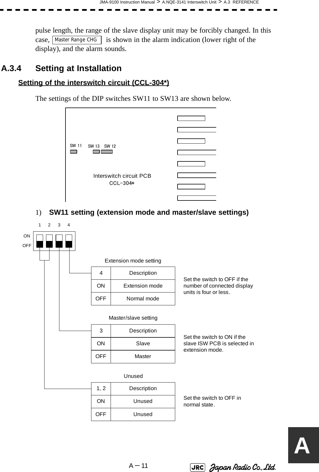
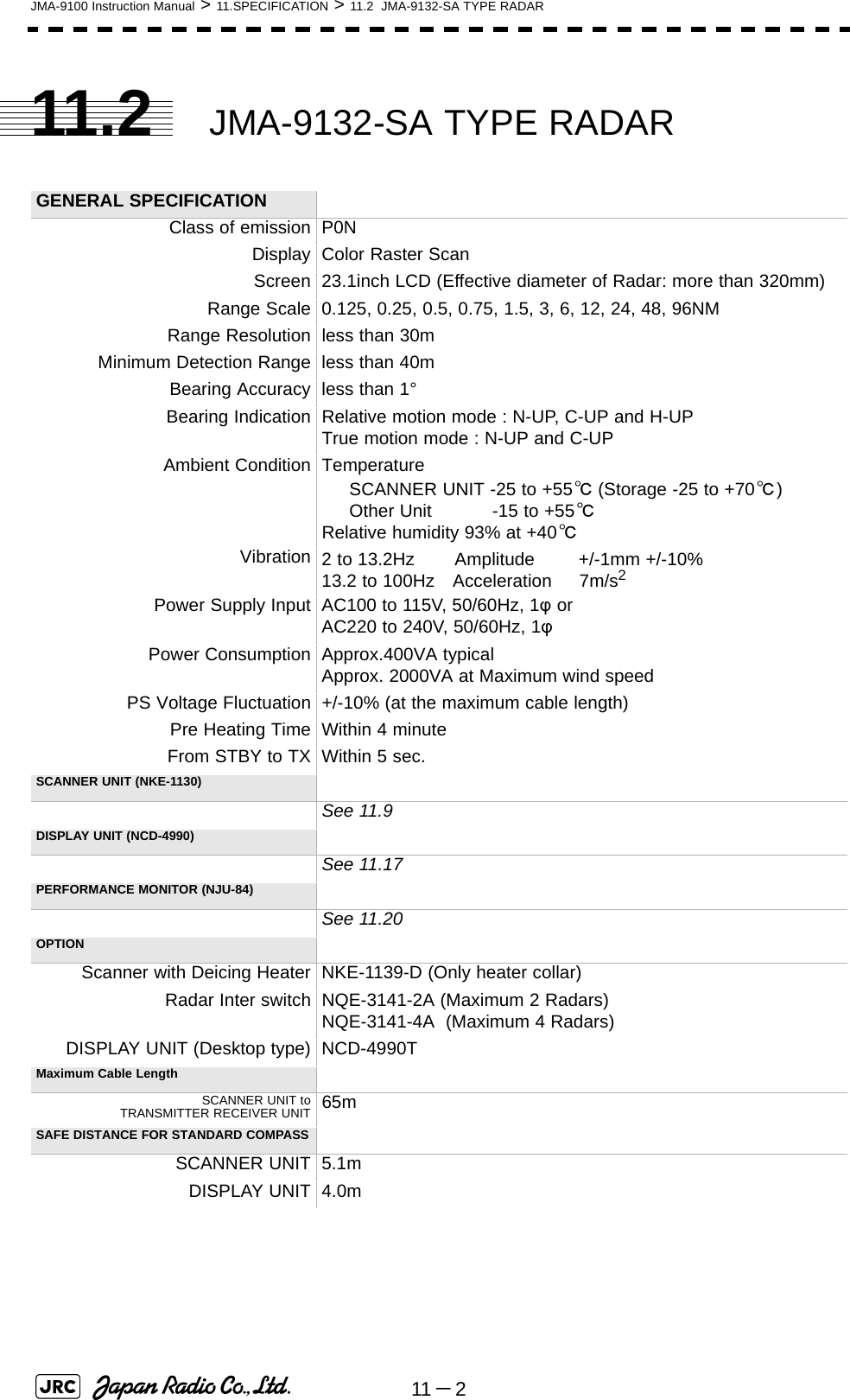
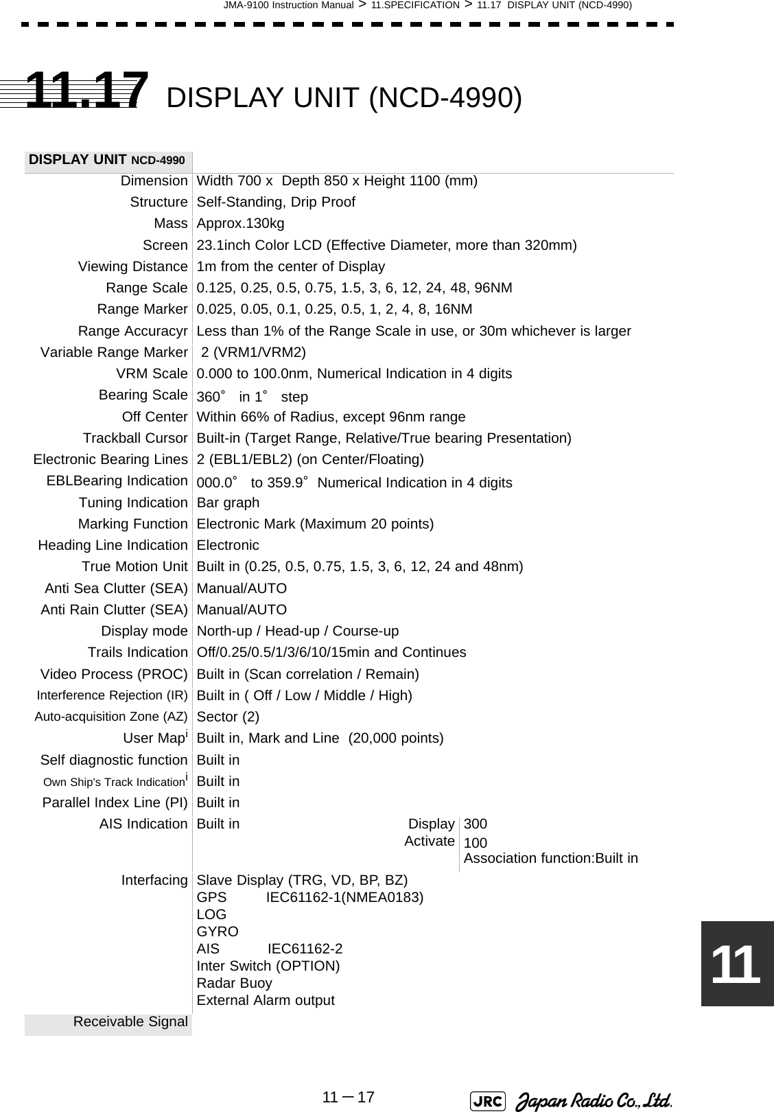
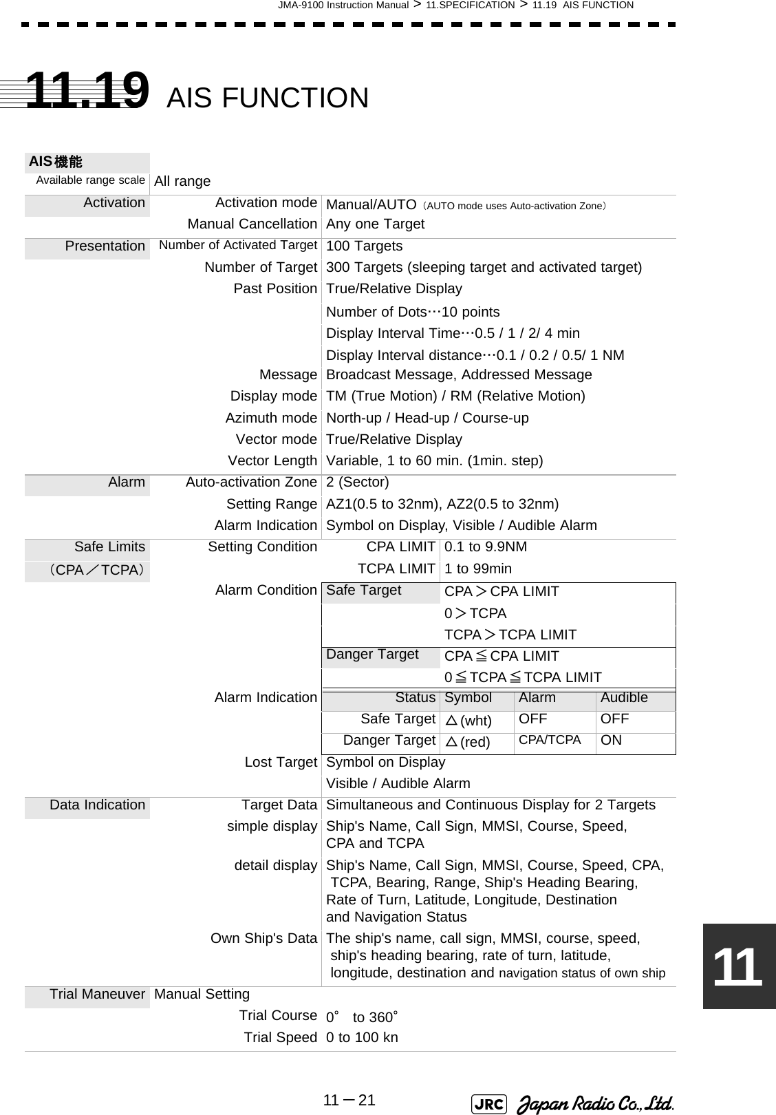
![JMA-9100 Instruction Manual > 11.SPECIFICATION > 11.11 SCANNER UNIT (NKE-1125-6/9)11 -111111.11 SCANNER UNIT (NKE-1125-6/9) SCANNER UNIT NKE-1125-6/9Dimension 6ft Height 536 x Swing Circle 1910 (mm)9ft Height 536 x Swing Circle 2825 (mm)Mass 6ft Approx. 55kg9ft Approx. 60kgPolarization HorizontalDirectional Characteristics Horizontal beam widthVertical beam widthSide lobe Level: 1.2° (6ft): 0.8° (9ft): 20°: below -26dB (within +/-10°): below -30dB (outside +/-10°)Revolution Approx.24rpmPower Supply for Motor AC100 - 115V、50/60Hz、1φ orAC220 - 240V、50/60Hz、1φMaximum Wind Velocity 51.5m/s (100knots)Transmitting Frequency 9410±30MHzTransmitting Power 25kWTransmitting Tube Magnetron[M1568BS]TX Pulse width / RepetitionFrequency SP1:0.07μs/2250HzMP1:0.2μs/2250Hz MP2:0.3μs/1900Hz、MP3:0.4μs/1400Hz LP1:0.8μs/750Hz、LP2:1.0μs/650Hz LP3:1.2μs/510Hz0.125、0.25、0.5NM :SP1 0.75NM :SP1/MP1 1.5NM :SP1/MP1/MP2/MP3 3NM :MP1/MP2/MP3/LP1 6NM :MP1/MP2/MP3/LP1/LP2 12NM :MP1/MP2/MP3/LP1/LP2 24NM :MP3/LP1/LP2 48NM :LP2 96NM :LP3Modulator Solid State Modulator CircuitDuplexer Circulator + Diode LimiterFront End Module Built-inIntermediate Frequency Amplifier Intermediate FrequencyBand WidthGainAmplifying Characteristics: 60MHz: 25/8/3MHz: more than 90dB: Logarithmic AmplifierOverall Noise Figure 7.5dB ( Typical)Tuning Manual/AUTO](https://usermanual.wiki/Japan-Radio/NKE1130.Users-Manual-3/User-Guide-994639-Page-45.png)
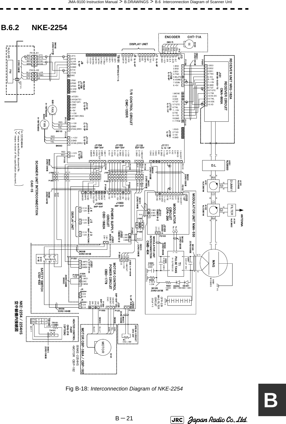
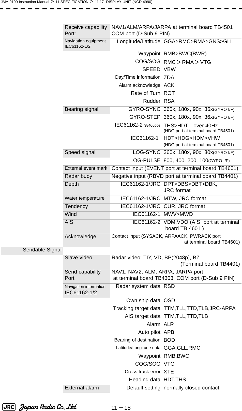
![11 -12JMA-9100 Instruction Manual > 11.SPECIFICATION > 11.12 SCANNER UNIT (NKE-2254-6HS)11.12 SCANNER UNIT (NKE-2254-6HS) SCANNER UNIT NKE-2254-6HSDimension Height 536 x Swing Circle 1910 (mm)Mass Approx. 55kgPolarization HorizontalDirectional Characteristics Horizontal beam widthVertical beam widthSide lobe Level: 1.2°: 20°: below -26dB (within +/-10°): below -30dB (outside +/-10°)Revolution Approx.24rpmPower Supply for Motor DC24VMaximum Wind Velocity 51.5m/s (100knots)Transmitting Frequency 9410±30MHzTransmitting Power 25kWTransmitting Tube Magnetron[M1568BS]TX Pulse width / RepetitionFrequency SP1:0.07μs/2250HzMP1:0.2μs/2250Hz MP2:0.3μs/1900Hz、MP3:0.4μs/1400Hz LP1:0.8μs/750Hz、LP2:1.0μs/650Hz LP3:1.2μs/510Hz0.125、0.25、0.5NM :SP1 0.75NM :SP1/MP1 1.5NM :SP1/MP1/MP2/MP3 3NM :MP1/MP2/MP3/LP1 6NM :MP1/MP2/MP3/LP1/LP2 12NM :MP1/MP2/MP3/LP1/LP2 24NM :MP3/LP1/LP2 48NM :LP2 96NM :LP3Modulator Solid State Modulator CircuitDuplexer Circulator + Diode LimiterFront End Module Built-inIntermediate Frequency Amplifier Intermediate FrequencyBand WidthGainAmplifying Characteristics: 60MHz: 25/8/3MHz: more than 90dB: Logarithmic AmplifierOverall Noise Figure 7.5dB ( Typical)Tuning Manual/AUTO](https://usermanual.wiki/Japan-Radio/NKE1130.Users-Manual-3/User-Guide-994639-Page-46.png)
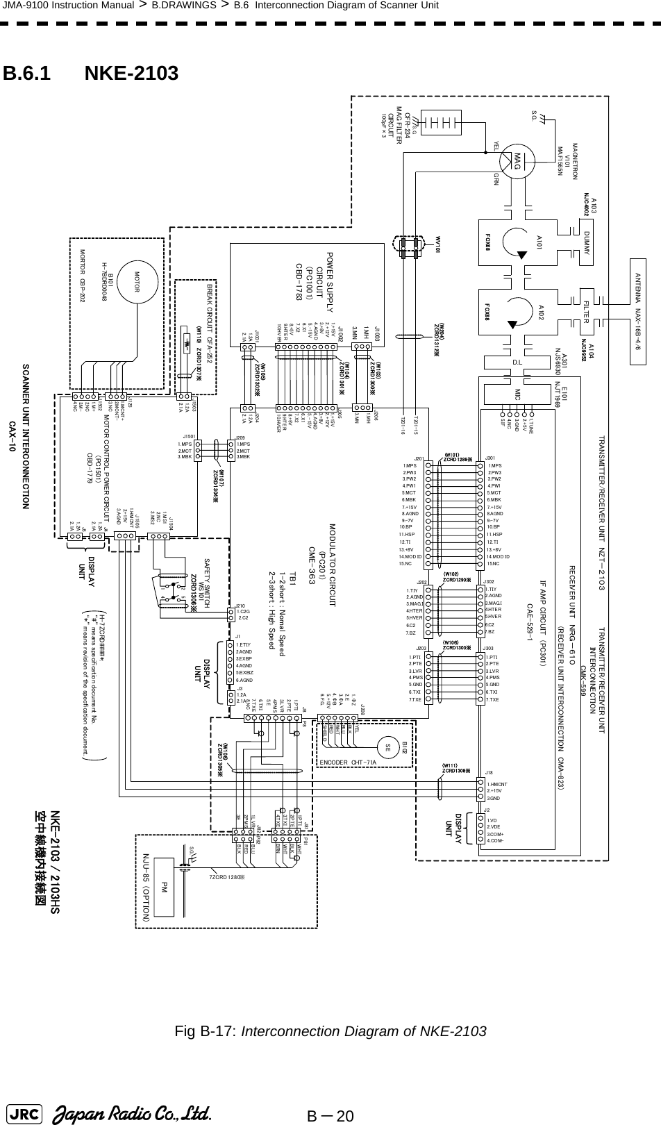
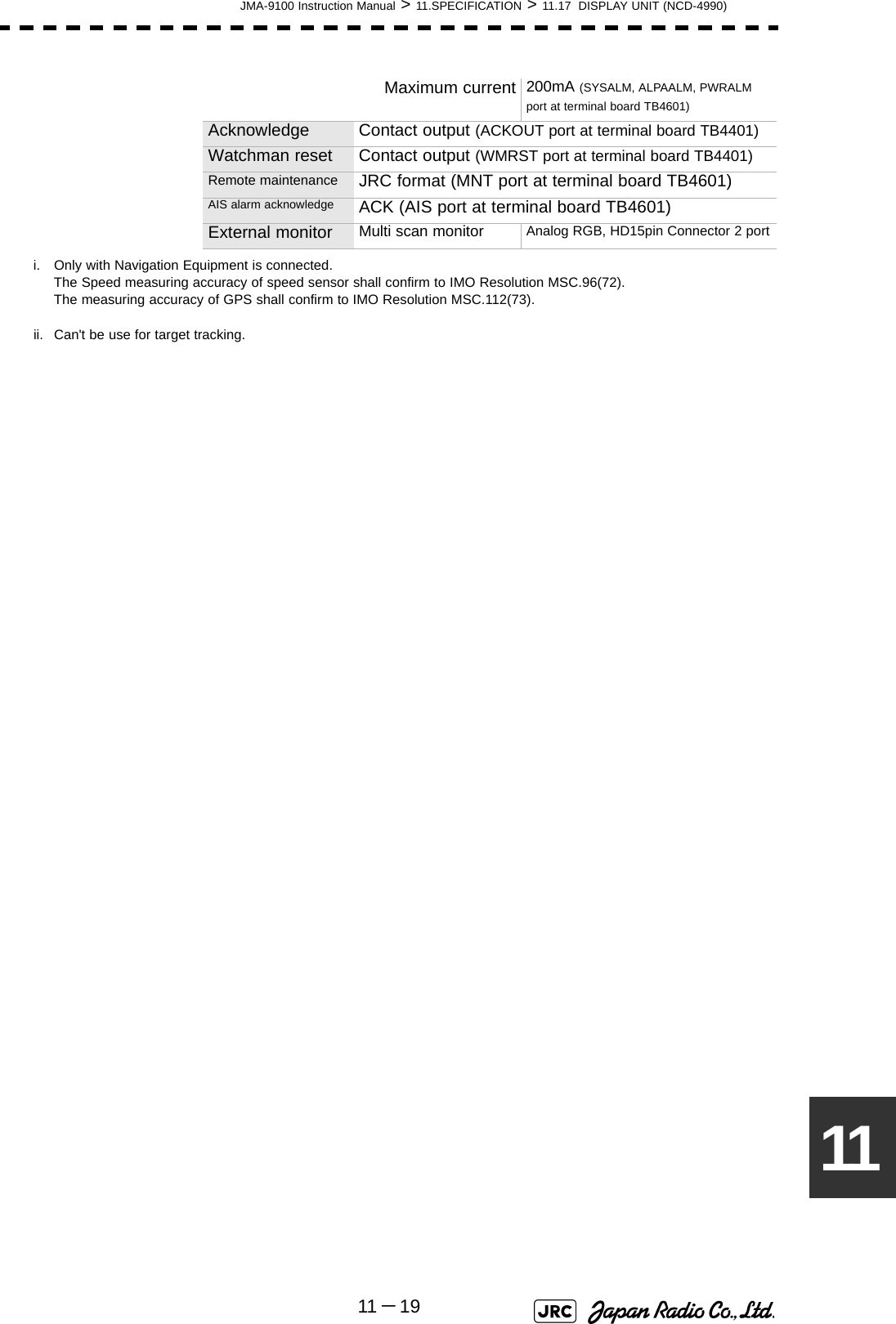
![JMA-9100 Instruction Manual > 11.SPECIFICATION > 11.13 SCANNER UNIT (NKE-2103-6)11 -131111.13 SCANNER UNIT (NKE-2103-6) SCANNER UNIT NKE-2103-6HSDimension Height 458 x Swing Circle 1910 (mm)Mass Approx. 40kgPolarization HorizontalDirectional Characteristics Horizontal beam widthVertical beam widthSide lobe Level: 1.2°: 20°: below -26dB (within +/-10°): below -30dB (outside +/-10°)Revolution Approx.24rpmPower Supply for Motor DC24VMaximum Wind Velocity 51.5m/s (100knots)Transmitting Frequency 9410±30MHzTransmitting Power 10kWTransmitting Tube Magnetron[MAF1565N]TX Pulse width / RepetitionFrequency SP1:0.08μs/2250HzMP1:0.25μs/1700Hz MP2:0.5μs/1200HzLP1:0.8μs/750Hz、LP2:1.0μs/650Hz0.125、0.25、0.5NM :SP1 0.75NM :SP1/MP1 1.5NM :SP1/MP1/MP2 3NM :MP1/MP2LP1 6NM :MP1/MP2/LP1/LP2 12NM :MP1/MP2/LP1/LP2 24NM :MP2/LP1/LP2 48NM :LP2 96NM :LP2Modulator Solid State Modulator CircuitDuplexer Circulator + Diode LimiterFront End Module Built-inIntermediate Frequency Amplifier Intermediate FrequencyBand WidthGainAmplifying Characteristics: 60MHz: 20/6/3MHz: more than 90dB: Logarithmic AmplifierOverall Noise Figure 7.5dB ( Typical)Tuning Manual/AUTO](https://usermanual.wiki/Japan-Radio/NKE1130.Users-Manual-3/User-Guide-994639-Page-47.png)
![11 -14JMA-9100 Instruction Manual > 11.SPECIFICATION > 11.14 SCANNER UNIT (NKE-2103-6HS)11.14 SCANNER UNIT (NKE-2103-6HS) SCANNER UNIT NKE-2103-6HSDimension Height 458 x Swing Circle 1910 (mm)Mass Approx. 40kgPolarization HorizontalDirectional Characteristics Horizontal beam widthVertical beam widthSide lobe Level: 1.2°: 20°: below -26dB (within +/-10°): below -30dB (outside +/-10°)Revolution Approx.24rpmPower Supply for Motor DC24VMaximum Wind Velocity 51.5m/s (100knots)Transmitting Frequency 9410±30MHzTransmitting Power 10kWTransmitting Tube Magnetron[MAF1565N]TX Pulse width / RepetitionFrequency SP1:0.08μs/2250HzMP1:0.25μs/1700Hz MP2:0.5μs/1200HzLP1:0.8μs/750Hz、LP2:1.0μs/650Hz0.125、0.25、0.5NM :SP1 0.75NM :SP1/MP1 1.5NM :SP1/MP1/MP2 3NM :MP1/MP2LP1 6NM :MP1/MP2/LP1/LP2 12NM :MP1/MP2/LP1/LP2 24NM :MP2/LP1/LP2 48NM :LP2 96NM :LP2Modulator Solid State Modulator CircuitDuplexer Circulator + Diode LimiterFront End Module Built-inIntermediate Frequency Amplifier Intermediate FrequencyBand WidthGainAmplifying Characteristics: 60MHz: 20/6/3MHz: more than 90dB: Logarithmic AmplifierOverall Noise Figure 7.5dB ( Typical)Tuning Manual/AUTO](https://usermanual.wiki/Japan-Radio/NKE1130.Users-Manual-3/User-Guide-994639-Page-48.png)
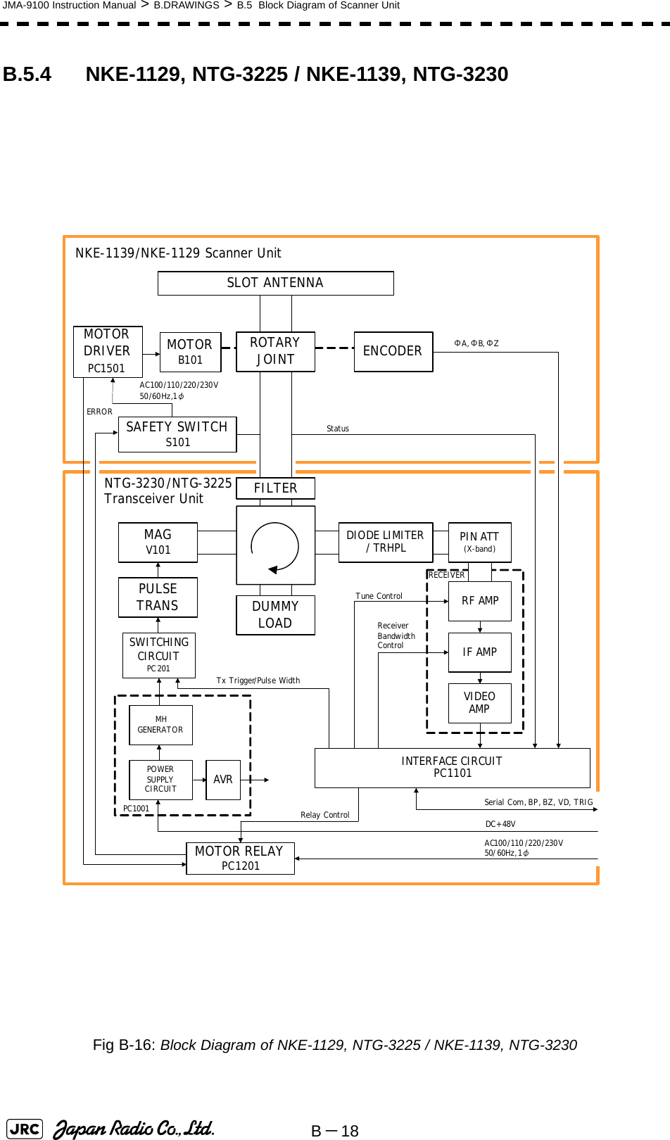
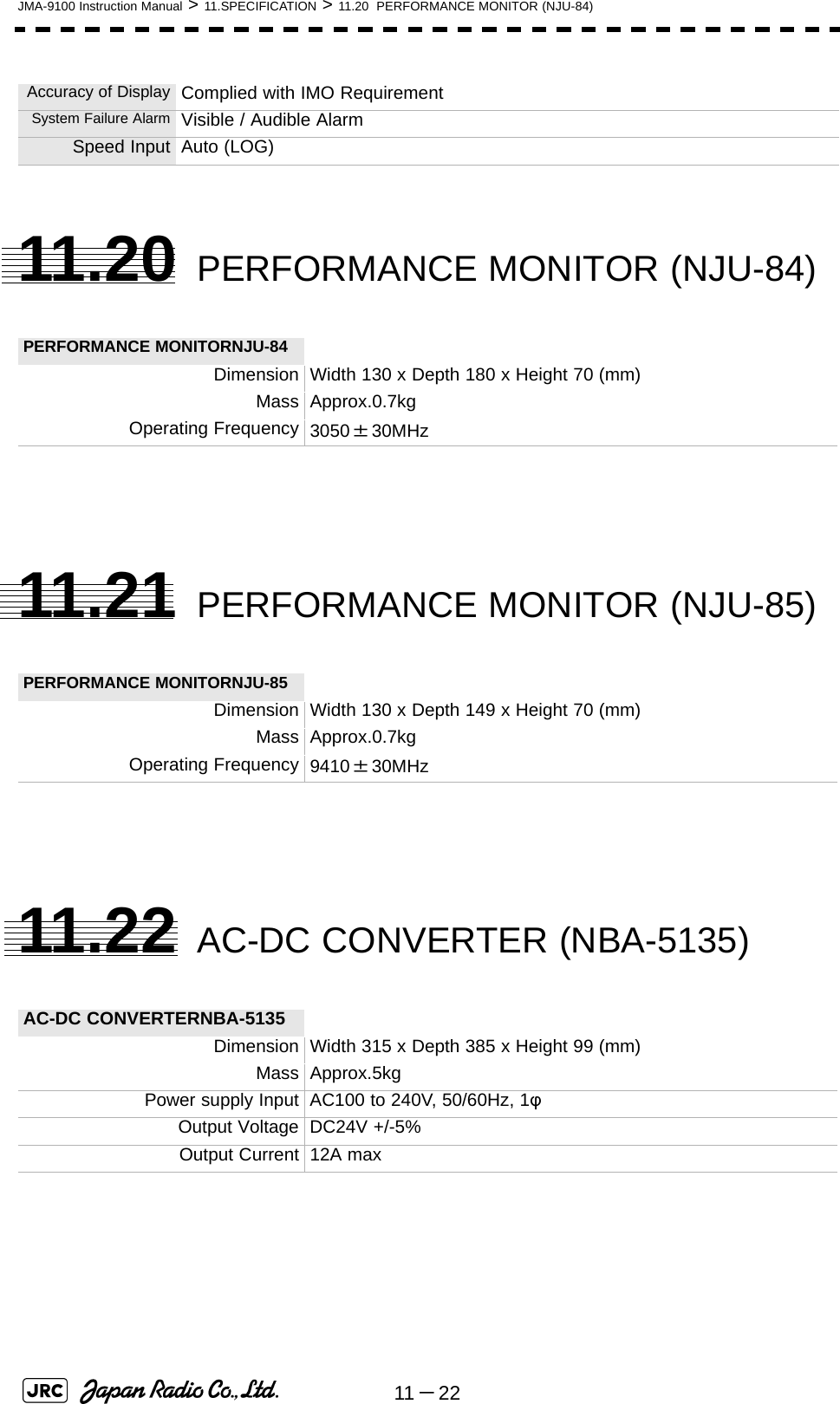
![JMA-9100 Instruction Manual > 11.SPECIFICATION > 11.15 TRANSMITTER RECEIVER UNIT (NTG-3230)11 -151111.15 TRANSMITTER RECEIVER UNIT (NTG-3230) SCANNER UNIT NTG-3230Dimension :Width 615 x Depth 365 x Height 615 (mm)構造 Wall Mount, Drip ProofMass Approx.33kgTransmitting Frequency 3050±20MHzTransmitting Power 30kWTransmitting Tube Magnetron [M1555]TX Pulse width / RepetitionFrequency SP1:0.07μs/2250HzMP1:0.2μs/2250Hz MP2:0.3μs/1900Hz、MP3:0.4μs/1400Hz LP1:0.8μs/750Hz、LP2:1.0μs/650Hz LP3:1.2μs/510Hz0.125、0.25、0.5NM :SP1 0.75NM :SP1/MP1 1.5NM :SP1/MP1/MP2/MP3 3NM :MP1/MP2/MP3/LP1 6NM :MP1/MP2/MP3/LP1/LP2 12NM :MP1/MP2/MP3/LP1/LP2 24NM :MP3/LP1/LP2 48NM :LP2 96NM :LP3Modulator Solid State Modulator CircuitDuplexer Circulator + TRHPLFront End Module Built-inIntermediate Frequency Amplifier Intermediate FrequencyBand WidthGainAmplifying Characteristics: 60MHz: 25/8/3MHz: more than 90dB: Logarithmic AmplifierOverall Noise Figure 7.5dB ( Typical)Tuning Manual/AUTO](https://usermanual.wiki/Japan-Radio/NKE1130.Users-Manual-3/User-Guide-994639-Page-49.png)
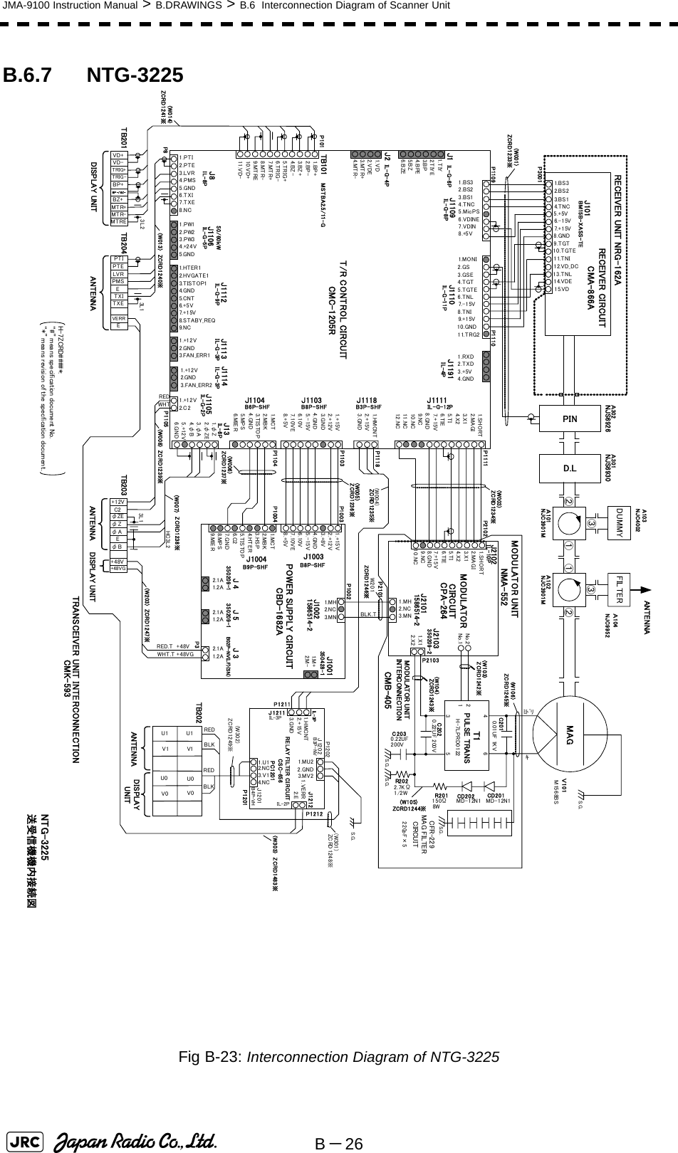
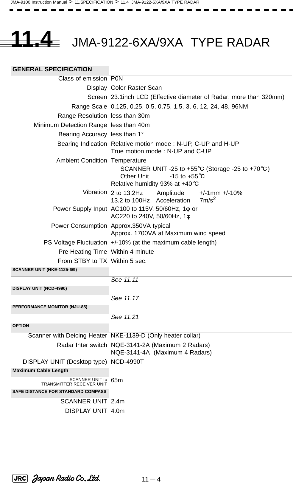
![11 -16JMA-9100 Instruction Manual > 11.SPECIFICATION > 11.16 TRANSMITTER RECEIVER UNIT (NTG-3225)11.16 TRANSMITTER RECEIVER UNIT (NTG-3225) SCANNER UNIT NTG-3225Dimension :Width 460 x Depth 227 x Height 461 (mm)構造 Wall Mount, Drip ProofMass Approx.15kgTransmitting Frequency 9410±30MHzTransmitting Power 25kWTransmitting Tube Magnetron[M1568BS]TX Pulse width / RepetitionFrequency SP1:0.07μs/2250HzMP1:0.2μs/2250Hz MP2:0.3μs/1900Hz、MP3:0.4μs/1400Hz LP1:0.8μs/750Hz、LP2:1.0μs/650Hz LP3:1.2μs/510Hz0.125、0.25、0.5NM :SP1 0.75NM :SP1/MP1 1.5NM :SP1/MP1/MP2/MP3 3NM :MP1/MP2/MP3/LP1 6NM :MP1/MP2/MP3/LP1/LP2 12NM :MP1/MP2/MP3/LP1/LP2 24NM :MP3/LP1/LP2 48NM :LP2 96NM :LP3Modulator Solid State Modulator CircuitDuplexer Circulator + Diode LimiterFront End Module Built-inIntermediate Frequency Amplifier Intermediate FrequencyBand WidthGainAmplifying Characteristics: 60MHz: 25/8/3MHz: more than 90dB: Logarithmic AmplifierOverall Noise Figure 7.5dB ( Typical)Tuning Manual/AUTO](https://usermanual.wiki/Japan-Radio/NKE1130.Users-Manual-3/User-Guide-994639-Page-50.png)
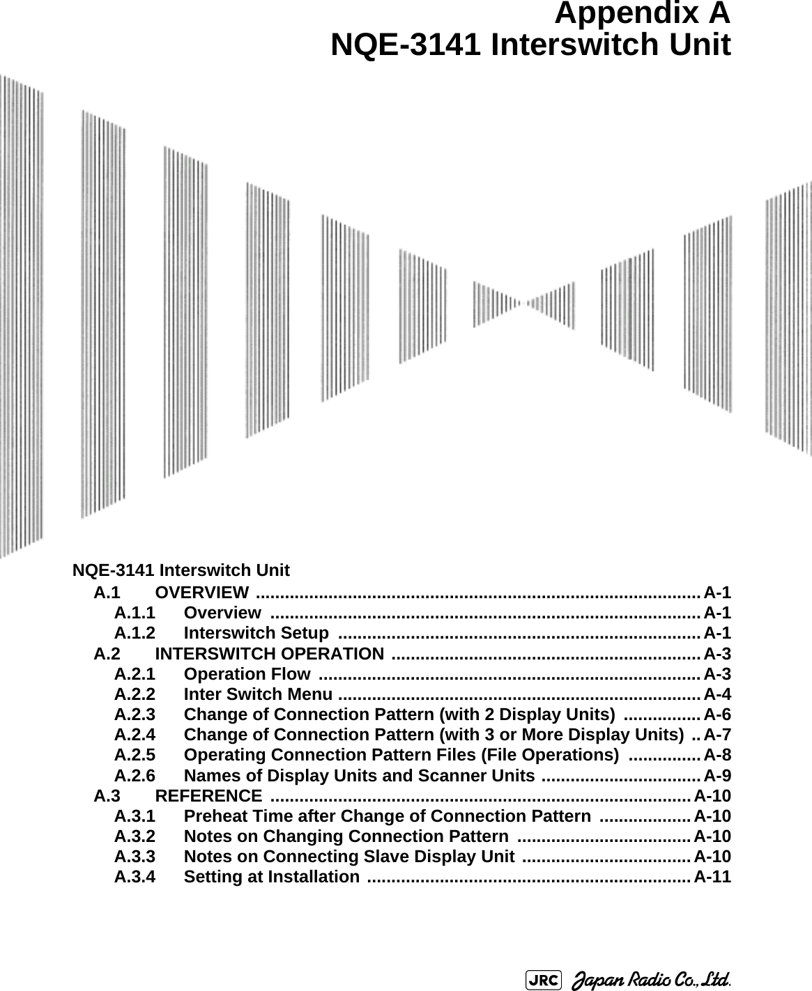
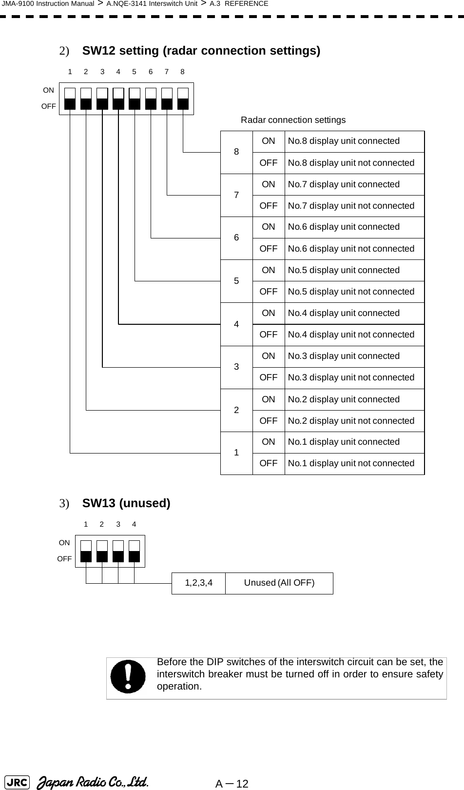
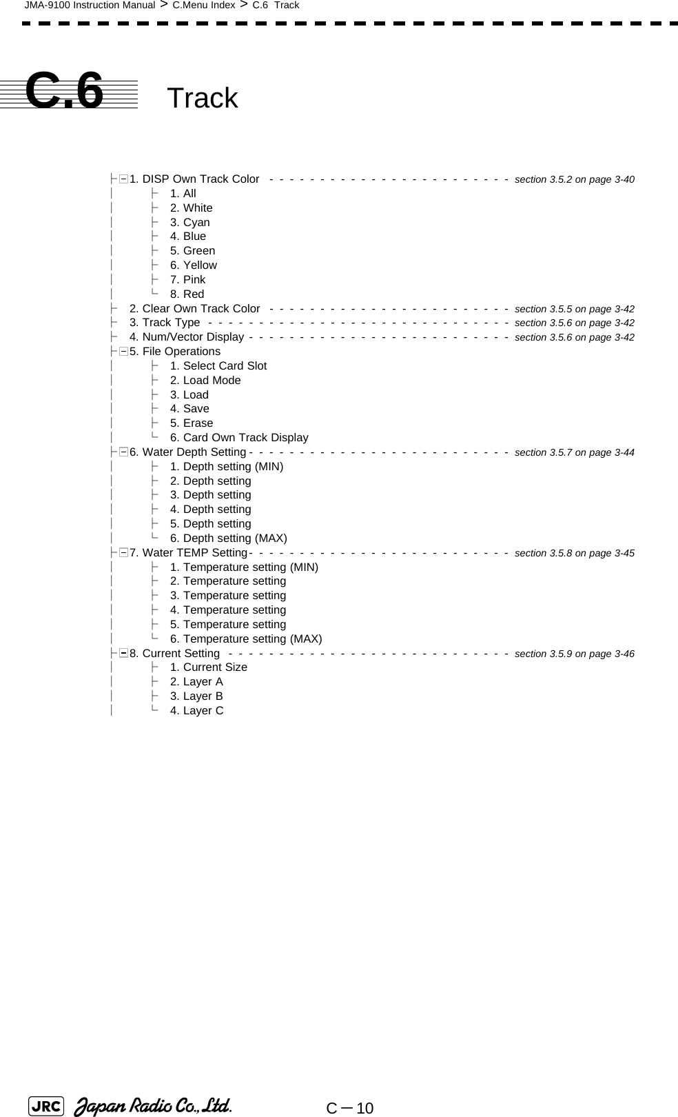
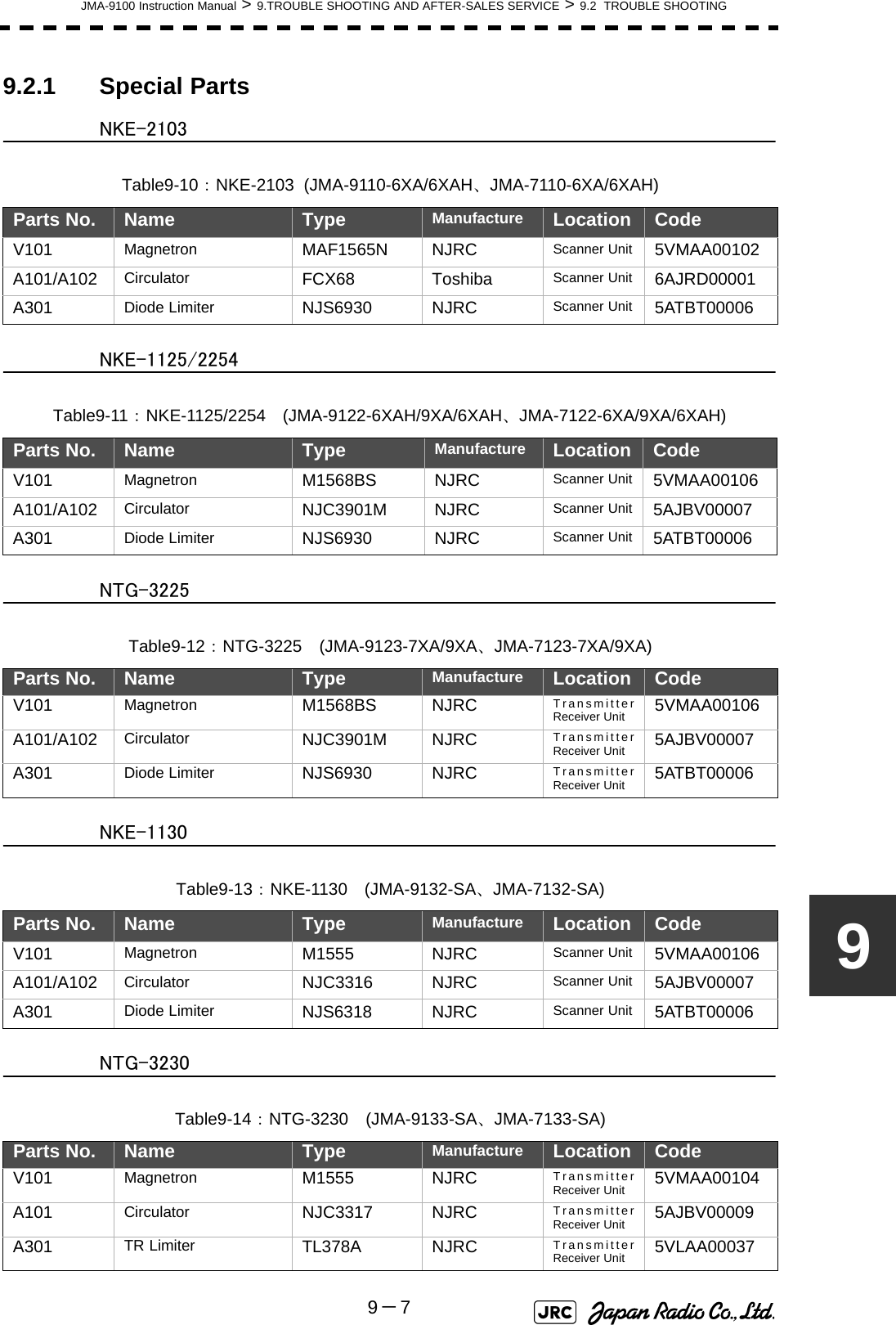
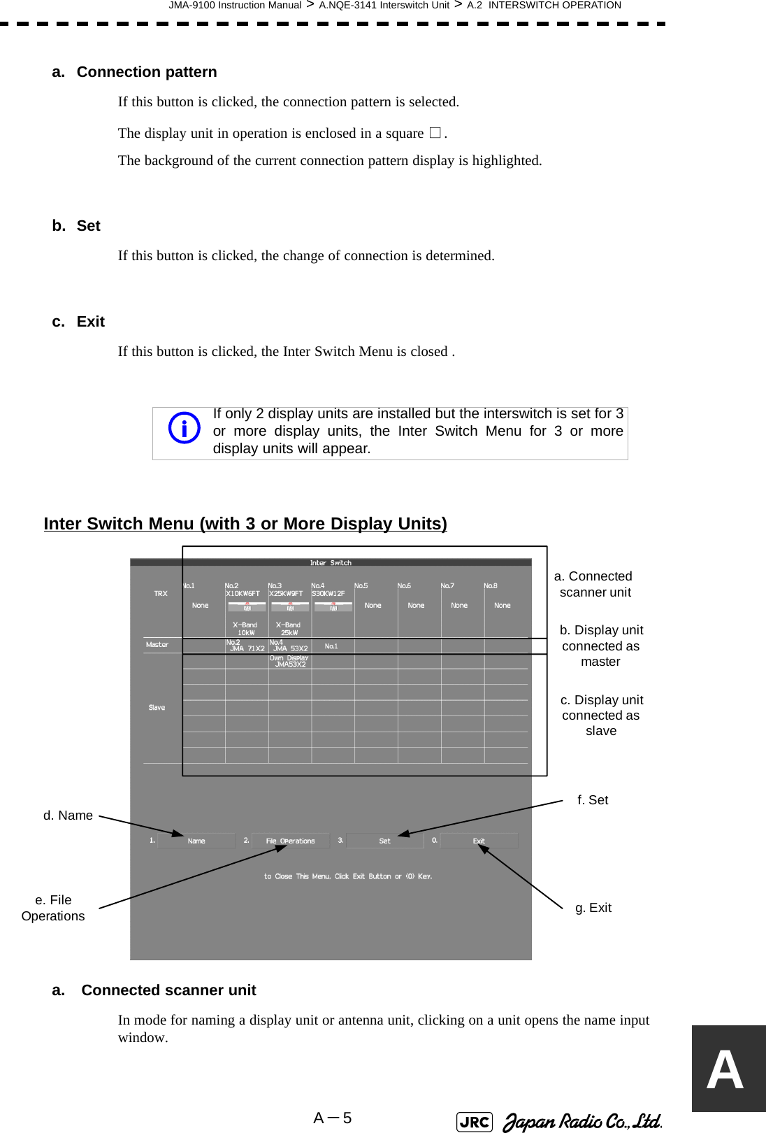
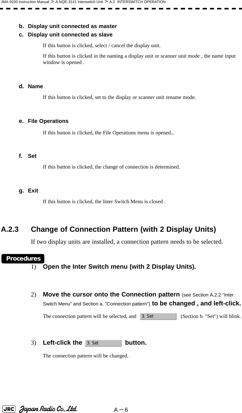
![A-4JMA-9100 Instruction Manual > A.NQE-3141 Interswitch Unit > A.2 INTERSWITCH OPERATIONA.2.2 Inter Switch MenuThe Inter Switch Menu can be opened only when the transmission standby state.Procedures1) Press the [TX/STBY] key to stop transmitting.The transmission standby state will be placed.2) Move the cursor onto the Interswitch connection change (upper left of the display), and left-click.The Inter Switch Menu will appear.Exit1) Left-click the button.The Inter Switch Menu will close. Inter Switch Menu (with 2 Display Units) 0.Exitb. Set c.ExitCurrent connection statusa. Connection patternDisplay unit in operation](https://usermanual.wiki/Japan-Radio/NKE1130.Users-Manual-3/User-Guide-994639-Page-62.png)
![A-8JMA-9100 Instruction Manual > A.NQE-3141 Interswitch Unit > A.2 INTERSWITCH OPERATIONA.2.5 Operating Connection Pattern Files (File Operations)Frequently used connection patterns can be read easily by saving interswitch connection patterns.[1] Loading connection patterns (Load)Procedures1) Open the Inter Switch Menu (with 3 or More Display Units).2) Left-click the button.The File Operations menu will appear.3) Left-click the button.Currently saved connection patterns in memory will be listed.4) Left-click the button corresponding to the file to be loaded.Confirmation Window will appear.5) Left-click the to load.The connection pattern will be changed. [2] Saving connection patterns (Save)Procedures1) Open the Inter Switch Menu (with 3 or More Display Units).2) Left-click the button.The File Operations window will appear.3) Left-click the button.The Save menu will appear.Currently saved connection patterns in memory will be listed.4) Left-click the button corresponding to the file to be saved.The Input File Name window will appear.5) Enter the file name to be saved.Up to 8 characters can be entered.For the input method on the character input screen, see Section 3.3.4.7 "Entering a character".The connection pattern will be saved when the name is input.2. File Operation3. Load1. Yes2. File Operation2. Save](https://usermanual.wiki/Japan-Radio/NKE1130.Users-Manual-3/User-Guide-994639-Page-66.png)
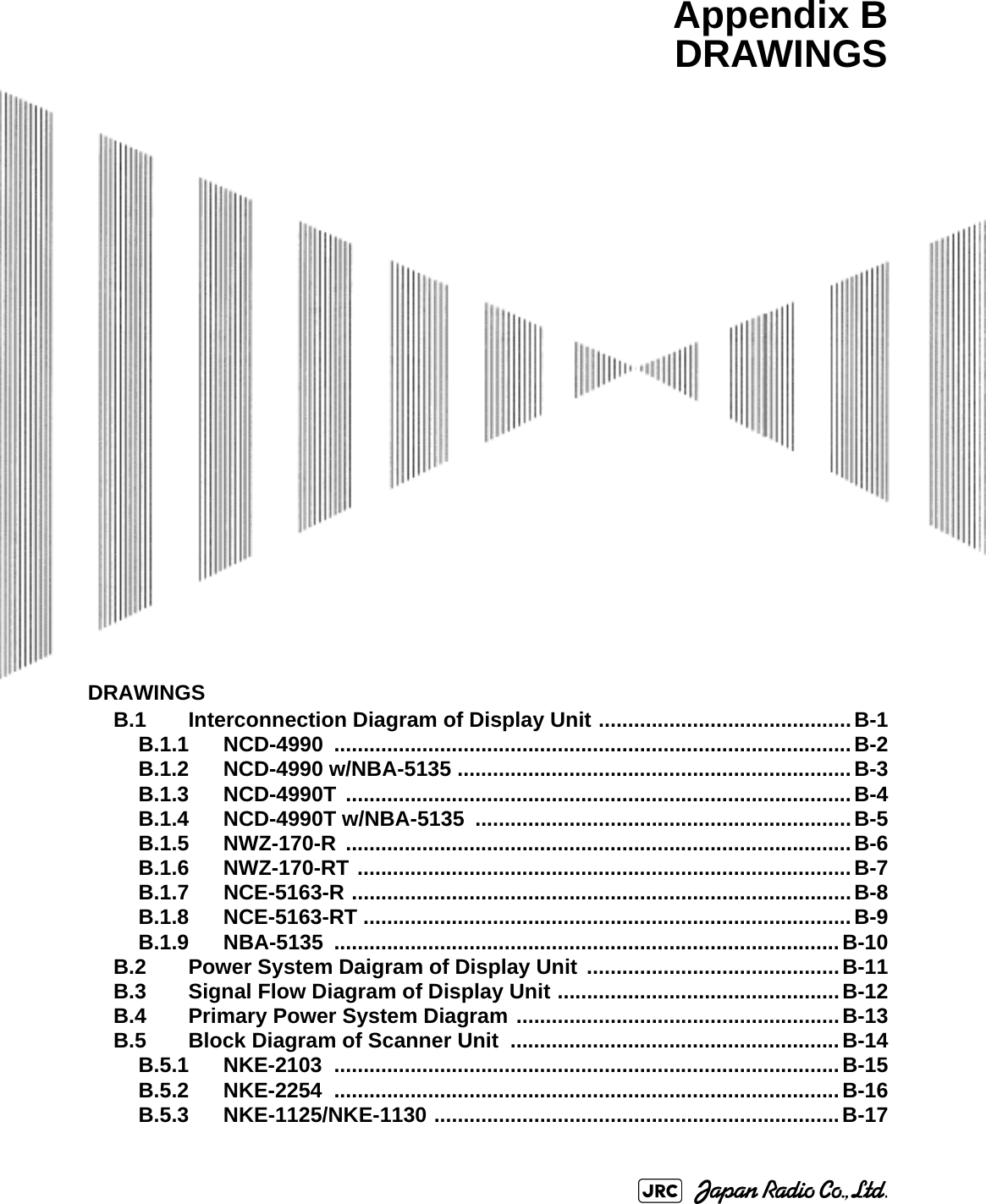
![JMA-9100 Instruction Manual > A.NQE-3141 Interswitch Unit > A.2 INTERSWITCH OPERATIONA-9A[3] Erasing a connection pattern (Erase)Procedures1) Open the Inter Switch Menu (with 3 or More Display Units).2) Left-click the button.The File Operations window will appear.3) Left-click the button. The Erase menu will appear.The list of connection patterns stored in the memory will be displayed.4) Left-click the button corresponding to the file to be erased.Confirmation Window will appear.5) Left-click the to load.The selected connection pattern is erased and the file name is deleted from the list. A.2.6 Names of Display Units and Scanner UnitsThe display units and antenna units can be named.Procedures1) Open the Inter Switch Menu (with 3 or More Display Units).2) Left-click the button. "Name" will be highlighted, indicating that the rename mode is activated.3) Move the cursor to the display unit (Section b. "Display unit connected as master" or Section c. "Display unit connected as slave") or scanner unit (Section a. "Connected scanner unit") to be renamed , and left-click.he Input IND Name or the Input TXRX Name window will appear.4) Input a new unit name.Up to 8 characters can be input as a unit name. For the input method on the character input menu, see Section 3.3.4.7 "Entering a character".The selected display unit or antenna unit will be renamed when the new name is input. 2. File Operation3. Erase1. Yes1. Name](https://usermanual.wiki/Japan-Radio/NKE1130.Users-Manual-3/User-Guide-994639-Page-67.png)