Japan Radio NKE1130 Marine Radar User Manual JMA 9100 series RADAR Instruction Manual
Japan Radio Co Ltd. Marine Radar JMA 9100 series RADAR Instruction Manual
Contents
- 1. Users Manual 1
- 2. Users Manual 2
- 3. Users Manual 3
- 4. Users Manual
Users Manual 2
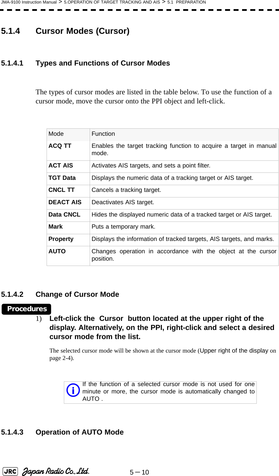
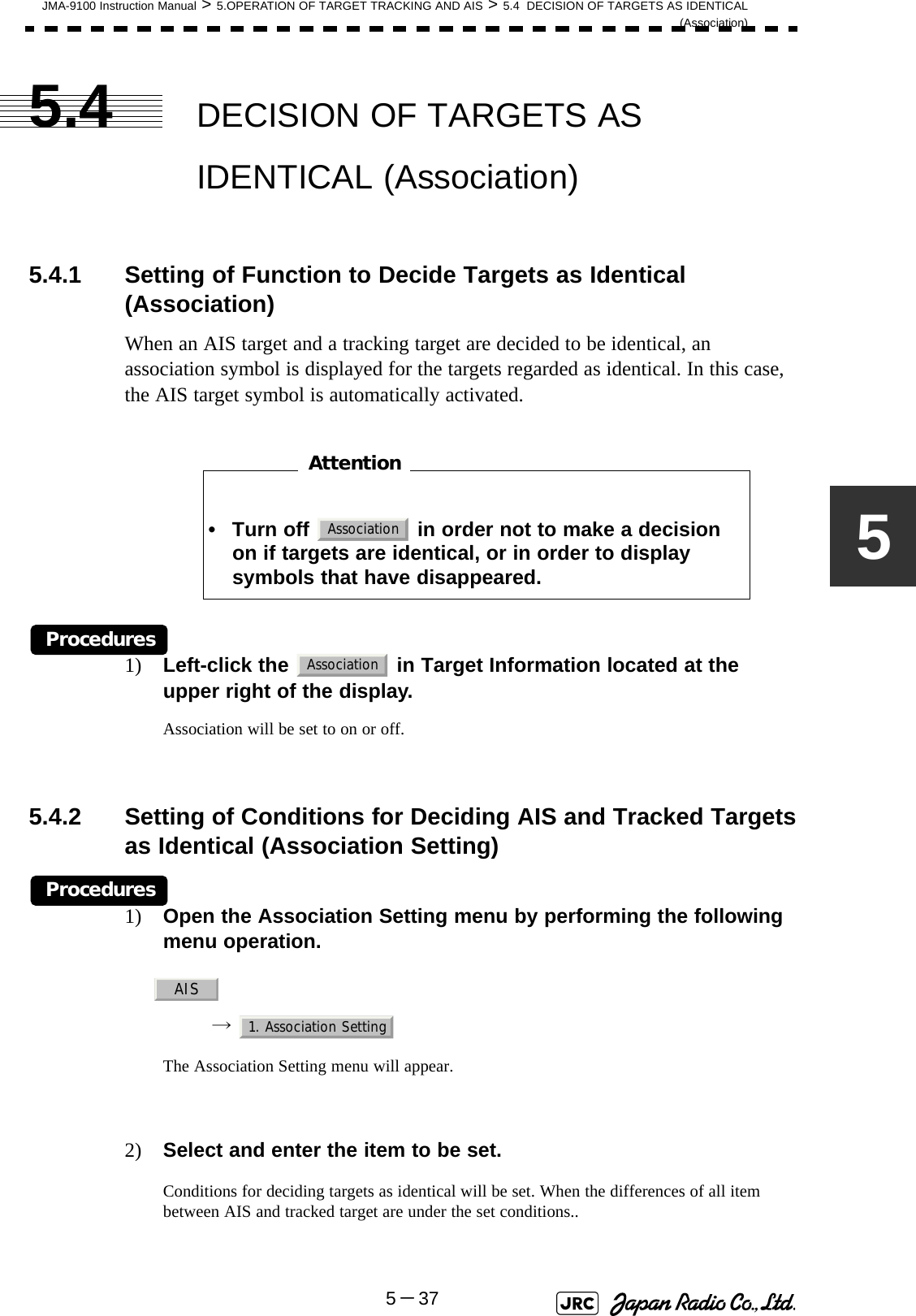
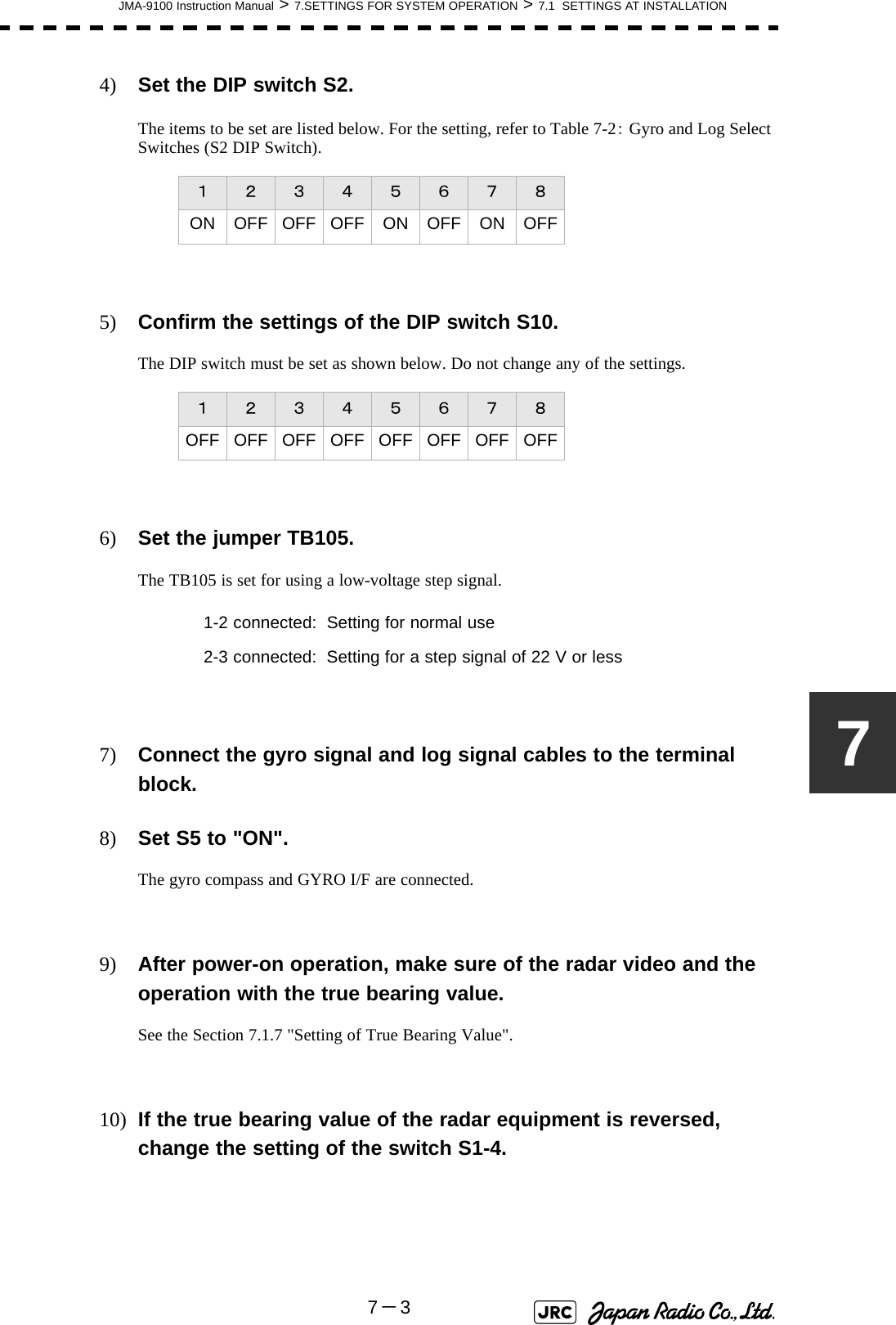
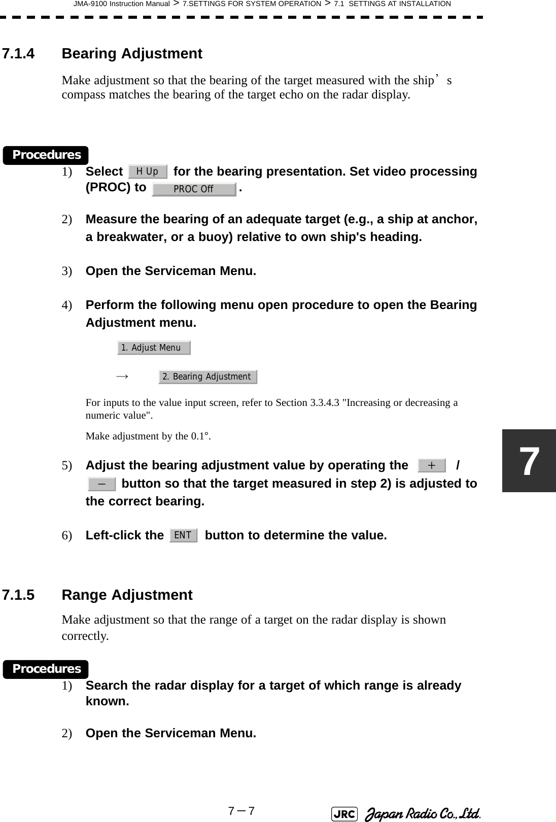
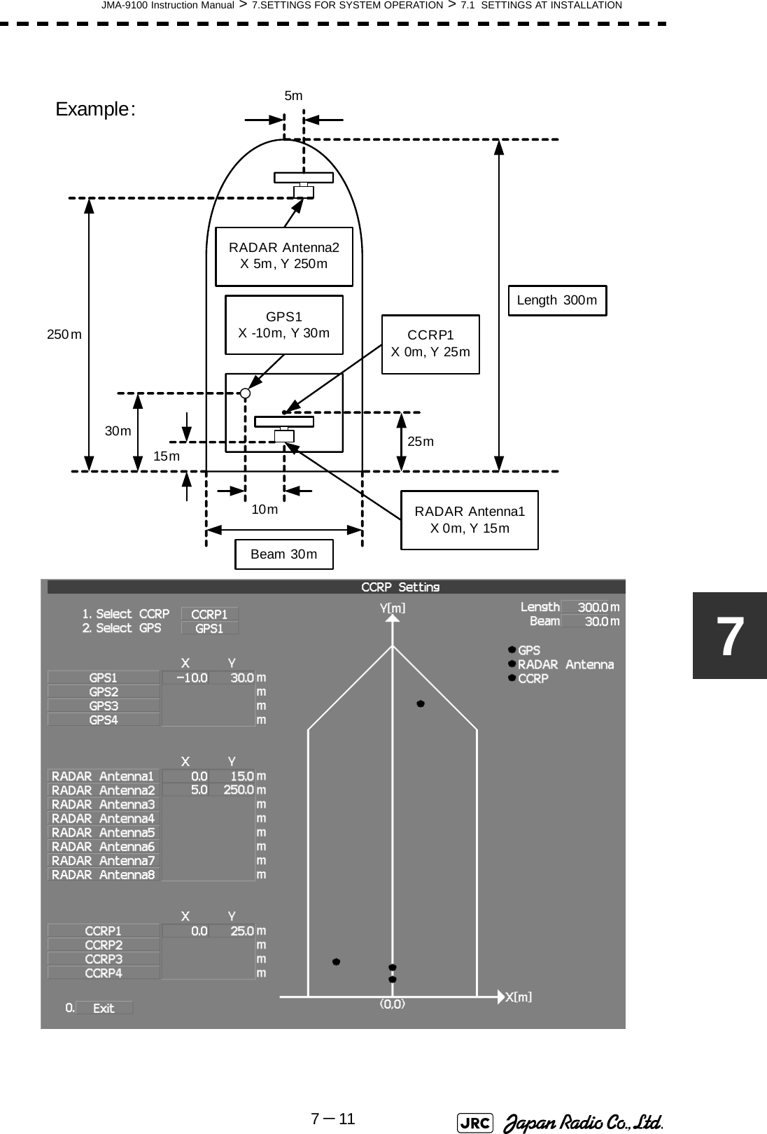
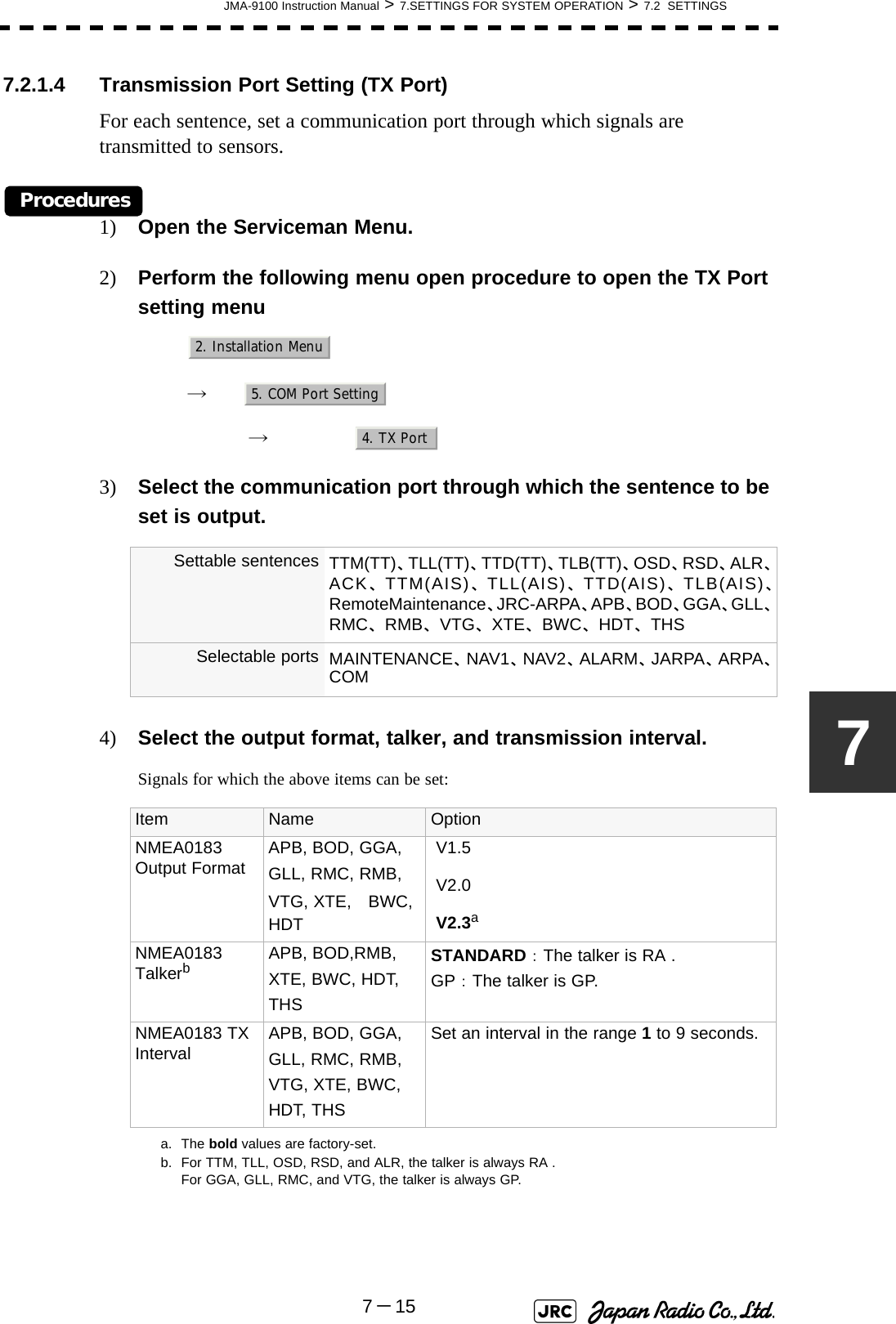
![JMA-9100 Instruction Manual > 5.OPERATION OF TARGET TRACKING AND AIS > 5.1 PREPARATION5-95[2] Relative Vector ModeThe relative vector does not represent the true motion of the target, but its relative relation with own ship. This means that a target with its relative vector directed to own ship (passing through the CPA Limit ring) will be a dangerous target. In the Relative Vector mode, it can be seen at a glance where the CPA Limit of the dangerous target is.Therefore, the True / Relative mode shall optionally be used for the purpose of observation: the True vector mode for grasping the true aspect of a target, and the Relative vector mode for grasping a target’s closest point of approach (CPA).Fig 5-5: Relative Vector5.1.3.3 Vector Length (Vector Time)The vector length of a target is proportional to its speed, and the vector time can be switched in a range of 1 to 60 minutes.The diagram below illustrates a vector length of a target for 6 minutes, and the tip of the vector represents the target's position expected to reach 6 minutes later.Fig 5-6: Vector LengthRefer to Section 5.1.6 "Setting Vectors (Vector Time)". The true vector isnot displayedRelative vectorCPA ringHLCurrent positionFuture predicted position(6 min later in this example)HL](https://usermanual.wiki/Japan-Radio/NKE1130.Users-Manual-2/User-Guide-994638-Page-1.png)
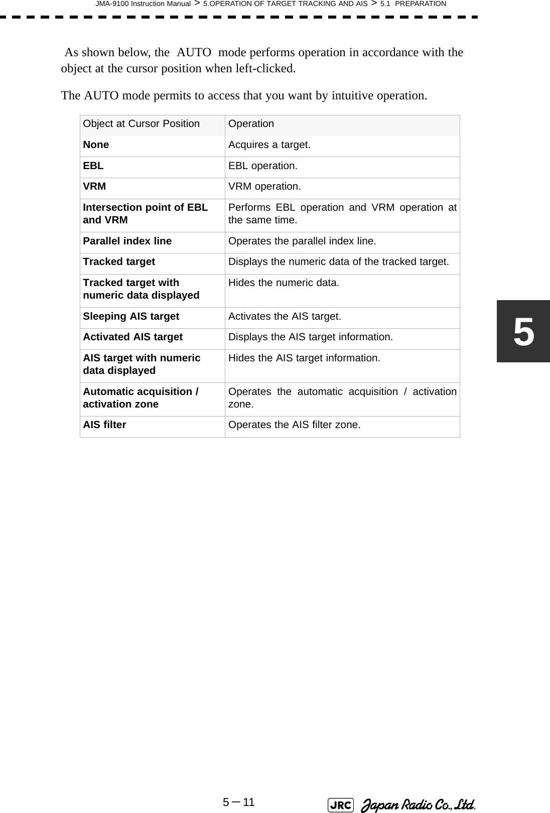
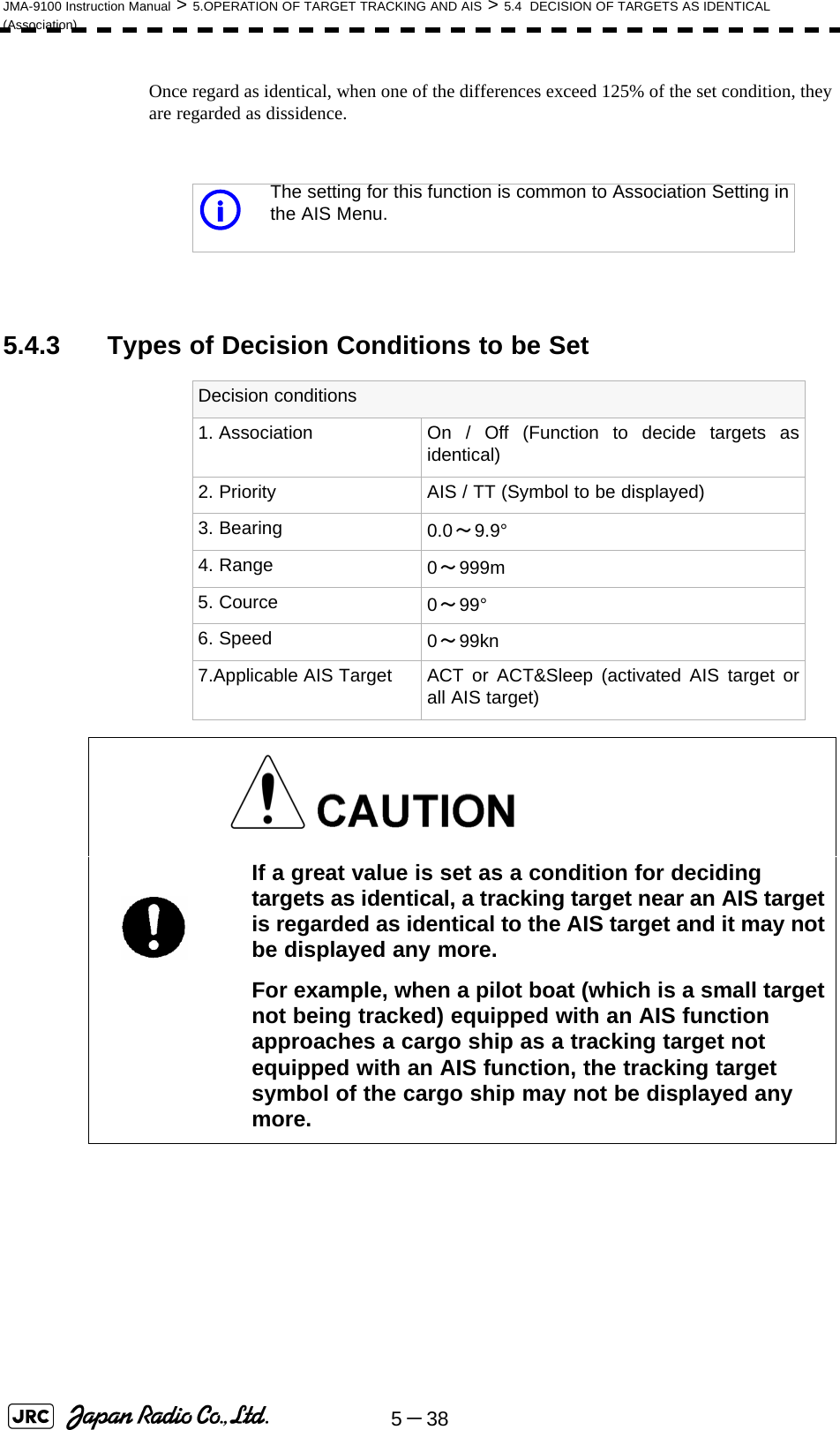
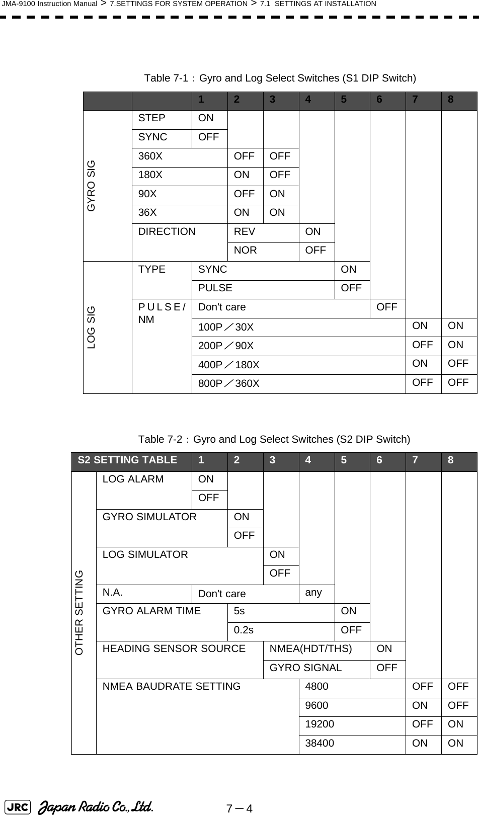
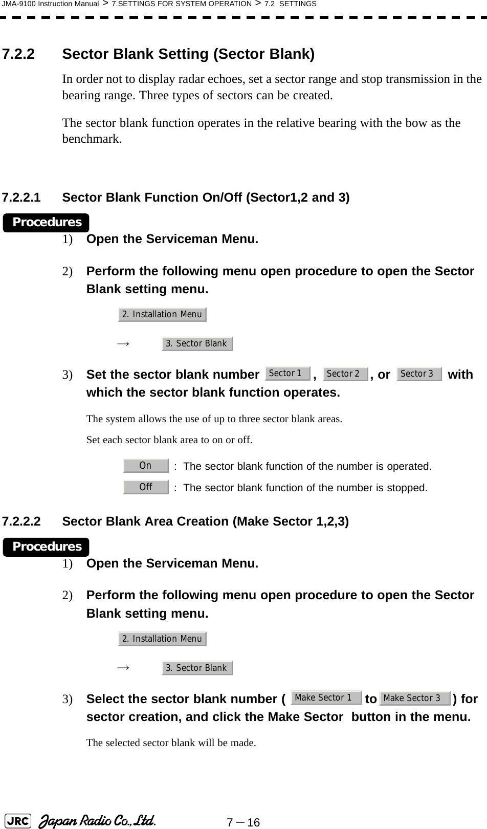
![JMA-9100 Instruction Manual > 5.OPERATION OF TARGET TRACKING AND AIS > 5.1 PREPARATION5-1355.1.6 Setting Vectors (Vector Time)Vector time can be set in minutes in the range 1 to 60 min.A true vector mode or relative vector mode can be selected.5.1.6.1 Setting vector time on the display (Vector)Procedures1) Left-click the target vector time setting button in the Target Information located at the lower right of the display.The Vector Time value input screen will appear.2) Enter the value to be set as vector time.For inputs to the value input screen, refer to Section 3.3.4 "Operation on Numeric Value, Latitude / Longitude and Character Input menu".5.1.6.2 Setting vector mode [T/R VECT] Procedures1) Press the [T/R VECT] key.The current vector mode (true vector) or (relative vector) will be displayed in the target vector display true / relative switching in Target Information located at the upper right of the display.5.1.7 Setting the GPS antenna locationSet the GPS antenna location. Set offset ranges in longitudinal direction and latitudinal direction from the own ship's reference position.For the setting procedure, refer to Section 7.1.9 "Setting of CCRP (CCRP Setting)". • If offset ranges are not set correctly, AIS symbols and radar echoes may be displayed shifted.• When offset ranges are set, latitude and longitude data received from the GPS is offset, and the offset data is displayed as the latitude and longitude of own ship’s position.TRAttention](https://usermanual.wiki/Japan-Radio/NKE1130.Users-Manual-2/User-Guide-994638-Page-5.png)
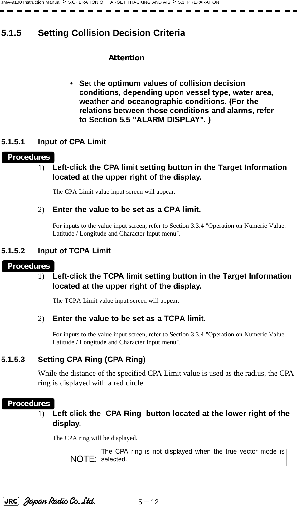
![5-14JMA-9100 Instruction Manual > 5.OPERATION OF TARGET TRACKING AND AIS > 5.2 TARGET TRACKING OPERATION5.2 TARGET TRACKING OPERATIONThis section explains how to use the target tracking function.The target tracking function automatically tracks a target, and displays the target's course and speed as vectors. The target tracking function calculates CPA and TCPA, and issues an alarm as needed.The tracking data is erased from memory when the power is turned off or during transmission standby.5.2.1 Acquiring Target [ACQ] Target acquisition can be performed on two modes, Automatic and Manual, and both modes can be used at the same time.5.2.1.1 Automatic acquisition[1] Turning On / Off the automatic acquisition and AIS activation (AZ Menu)Procedures1) Open the AZ menu by following menu operations.The AZ Menu will appear.2) Left-click the item button of or . The acquisition / activation zone 1 (AZ1) or acquisition / activation zone 2 (AZ2) will be set to on or off. NOTE: If the number of targets being tracked has reached theallowable maximum and other targets (not being tracked) gointo the acquisition/activation zone, automatically acquiredtargets are canceled in ascending order of danger.The position of the scanner shall be at the centre of the azimuthor range in the acquisition/activation zone.:The acquisition / activation zone is turned on. The mark and target ID number are put to an acquired target andmove with the target. The vectors are displayed within 1minute. AIS targets are activated.:The acquisition/activation zone is turned off. Theacquisition/activation zone will disappear from the radardisplay, but the system continues to track the acquiredtarget. The activated AIS targets remain activate.AZ1. AZ1 2. AZ2On12Off](https://usermanual.wiki/Japan-Radio/NKE1130.Users-Manual-2/User-Guide-994638-Page-6.png)
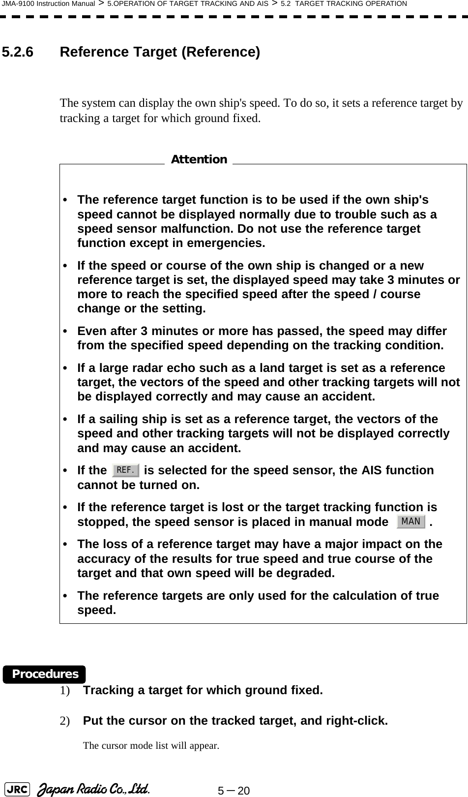
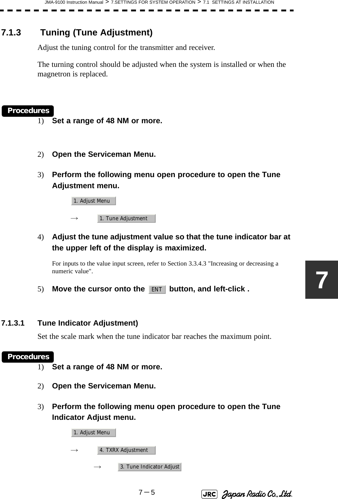
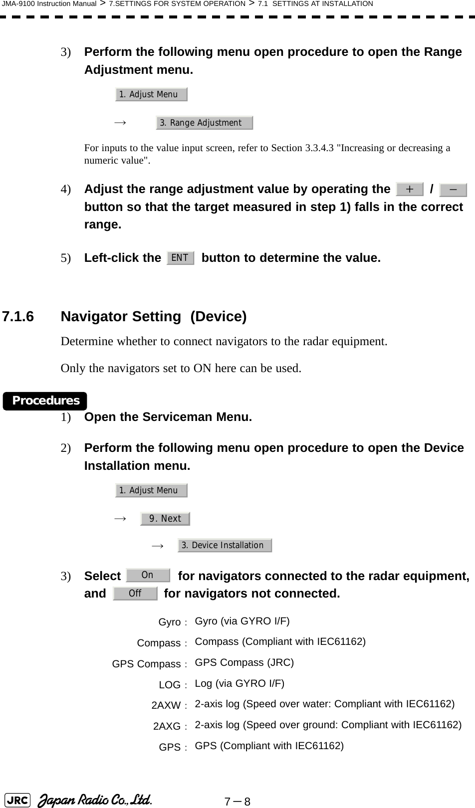
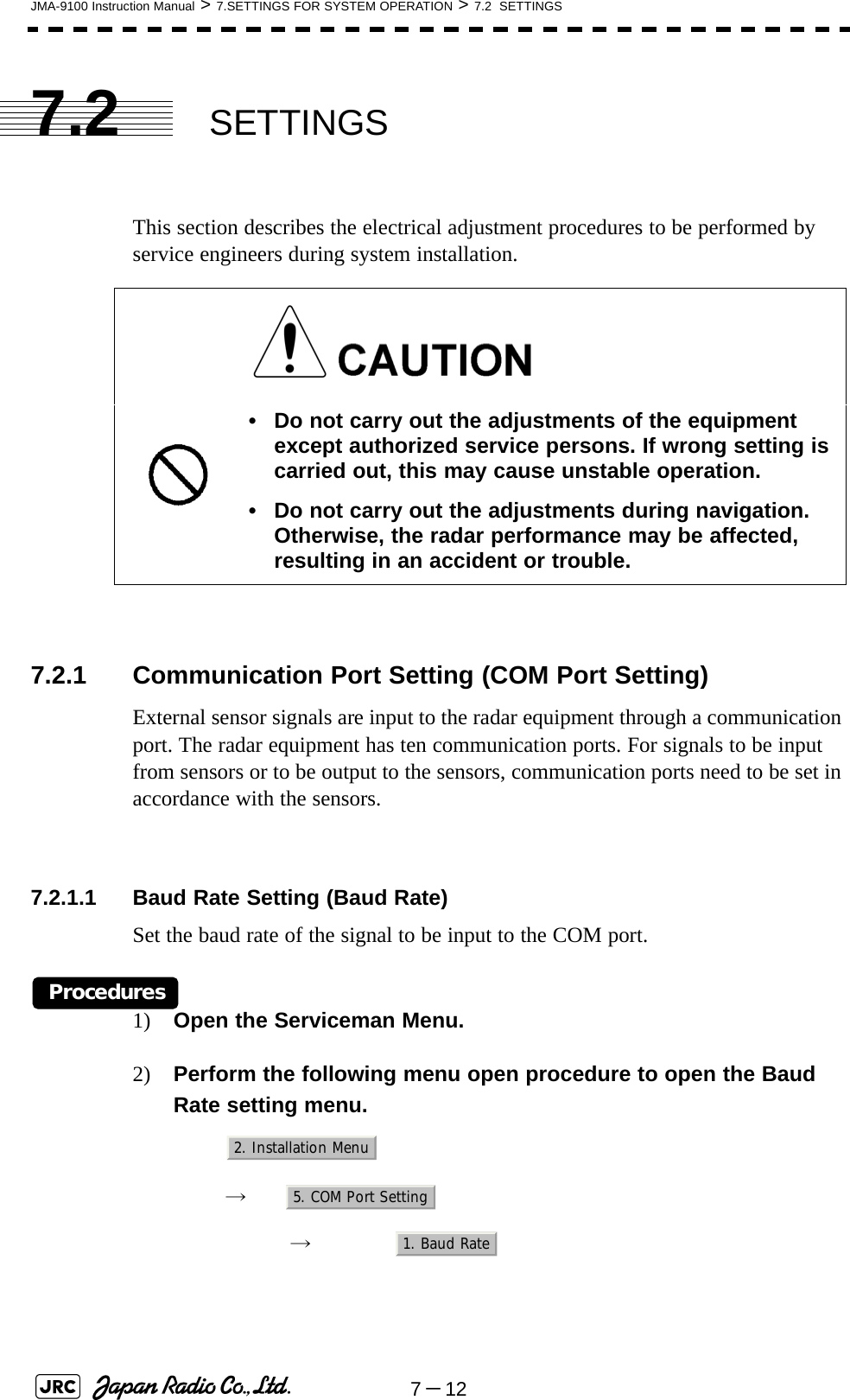
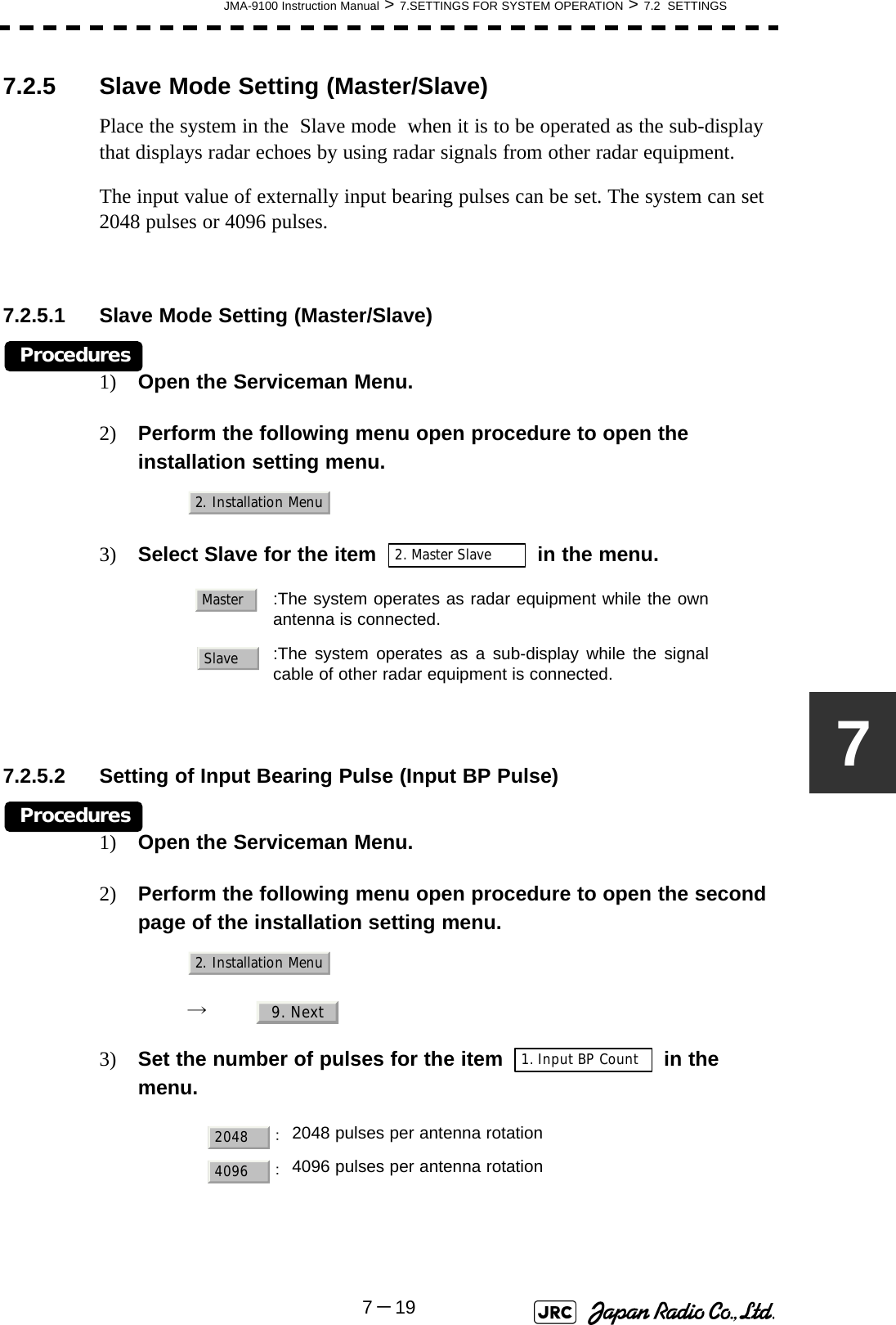
![JMA-9100 Instruction Manual > 5.OPERATION OF TARGET TRACKING AND AIS > 5.2 TARGET TRACKING OPERATION5-155[2] Creating the automatic acquisition and AIS activation Zone (Make AZ)Procedures1) Open the AZ menu by following menu operations.=捕捉・活性化メニュー (AZ Menu)が開きます。2) Left-click the item button of or .The range setting of the acquisition / activation zone 1 (AZ1) or acquisition / activation zone 2 (AZ2) will be started.3) Set the starting azimuth and range by turning the [EBL] dial and [VRM] dial, and left-click.4) Set the ending azimuth and range by turning the [EBL] dial and [VRM] dial, and left-click.The acquisition / activation zone will be determined. 5.2.1.2 Manual Acquisition [ACQ MANUAL] Procedures1) Move the cursor onto the target to be acquired, and press the [ACQ MANUAL] key.The target will be acquired and the initial acquisition symbol will be displayed.The vector will be displayed within one minute.To perform operation only in the manual acquisition mode without automatic acquisition/activation, turn off the automatic acquisition/activation function.NOTE: If more targets are acquired manually in the condition that themaximum number of targets are under tracking, the targetscannot acquired.AZ3. Make AZ14. Make AZ2Target manually acquired .The initial acquisition symbol is displayed.Target that has passed for 1 min.The acquisition symbol and vector are displayed .](https://usermanual.wiki/Japan-Radio/NKE1130.Users-Manual-2/User-Guide-994638-Page-7.png)
![5-16JMA-9100 Instruction Manual > 5.OPERATION OF TARGET TRACKING AND AIS > 5.2 TARGET TRACKING OPERATION[1] Use of Automatic and Manual Acquisition ModesUse the manual acquisition mode while the automatic acquisition mode is on.Manually acquire the target to which particular attention should be paid, and get the other targets automatically acquired. If a new target appears exceeding the maximum number of targets, the manually acquired target is displayed even in the background until it gets out of the display. However, automatically acquired targets are canceled starting far distance from own ship. 5.2.2 Canceling Unwanted Tracked Targets [ACQ CANCEL] Unwanted tracked targets can be canceled one by one in the following cases:•Tracking is no longer necessary for targets with which vectors/symbols are displayed after being acquired and tracked.•The number of vectors on the radar display needs to be reduced for easy observation.When targets are to be re-acquired from the beginning, all the current vectors can also be canceled.5.2.2.1 Canceling targets one by one [ACQ CANCEL] Procedures1) Put the cursor on the tracked target to the desired for canceling target, and press the [ACQ CANCEL] key.The vectors and symbols of the tracked targets will disappear, and only the radar video remain.5.2.2.2 Canceling all targets collectively [ACQ CANCEL] Procedures1) Press the [ACQ CANCEL] key for 5 seconds.The vectors and symbols of all the targets will disappear, and only the radar videos remain. NOTE: When all the targets have been canceled, the system stopstracking them. Thus, you need to re-acquire targets in manualor automatic acquisition mode. Do not cancel all the targetsunless otherwise required.](https://usermanual.wiki/Japan-Radio/NKE1130.Users-Manual-2/User-Guide-994638-Page-8.png)
![JMA-9100 Instruction Manual > 5.OPERATION OF TARGET TRACKING AND AIS > 5.2 TARGET TRACKING OPERATION5-1755.2.3 Tracked Target Data Display [TGT DATA] 5.2.3.1 Type of Data Display (Target Information)The target for which its numeric data is displayed is marked with a symbol to distinguish from other targets.If a target's data is displayed, but without the symbol , such a target exists outside the currently displayed radar display.5.2.3.2 Method of Displaying Numeric Data [TGT DATA] Procedures1) Put the cursor on the tracked target for which numeric data is to be displayed, and press the [TGT DATA] key.Then, the data of the designated target will appear, it will be marked with a symbol . The target data will remain on the radar display until the target is lost and its vector disappears, or until another target is designated.If a target with the mark is designated, only its true bearing and range will appear until its vector appears. When a target or own ship changes its course, or when a new target is acquired, its vector may not reach a given level of accuracy until 3 minutes or more has passed after such course change or target acquisition.Even if 3 minutes or more has passed, the vector may include an error depending upon the tracking conditions.Target DataTarget identification (TT ID) ID number of the targetTrue bearing(BRG) 0.1° unitRange 0.01NM untiCource 0.1° unitSpeed 0.1knot unitClosest point of approach (CPA) 0.01NM unitTime to CPA (TCPA) 0.1min unitBow crossing range (BCR) 0.01NM unitBow crossing time (BCT) 0.1min unitAttention12121212](https://usermanual.wiki/Japan-Radio/NKE1130.Users-Manual-2/User-Guide-994638-Page-9.png)
![5-18JMA-9100 Instruction Manual > 5.OPERATION OF TARGET TRACKING AND AIS > 5.2 TARGET TRACKING OPERATION5.2.3.3 Cancellation of Numeric Data Display (CNCL Data)Procedures1) Put the cursor on the tracked target with which numeric data is displayed, and right-click.The cursor mode list will appear.2) Left-click button.The numeric value will disappear.5.2.4 Displaying Target ID No.(Target Number Display)A target ID number is a value displayed beside the acquisition symbol when a target is acquired.A target ID number 1 to 100 is assigned to each target in acquisition order. Once a target ID number is assigned, it identifies the target until the target is lost or the target acquisition is canceled.Procedures1) Open the TT Menu by following menu operation.2) Left-click the item button of Target Number Display will appear.3) Press the [numeric] key corresponding to the display method to be set.If there are many tracking targets and their symbol display is confusing, set Target Number Display to off to view the radar display easily. : Displays target ID numbers.: Hides target ID numbers.: Displays target ID number with target track.An ID number is always displayed for only targets with whichnumeric data is displayed.6. CNCL DataTT4. Target Number DisplayOnOffTarget Tracki](https://usermanual.wiki/Japan-Radio/NKE1130.Users-Manual-2/User-Guide-994638-Page-10.png)
![JMA-9100 Instruction Manual > 5.OPERATION OF TARGET TRACKING AND AIS > 5.2 TARGET TRACKING OPERATION5-1955.2.5 Adding Tracked Target ID Name (Name)The system can enter a name for each of tracking targets that have been acquired.Procedures1) Put the cursor on the tracked target, and right-click.The cursor mode list will appear.2) Left-click The Property will appear.3) Left-click the item button of .The setting items for ship name (Name) will be displayed.4) Select the input method.5.2.5.1 Entering a new ship name (Input)5) Input a new ship name.Up to 8 characters can be input as a ship name.For the input method on the character input screen, see Section 3.3.4.7 "Entering a character".The input name by selecting is saved in Data Base .5.2.5.2 Selecting one of previously input ship names (Data Base)5) Press the [numeric] key corresponding to the ship name to be selected.The selected ship name will be entered. :Selection of one of previously input shipnames.When this method is selected, a list of shipnames that have been input by selecting will be displayed.:Input of a new ship name. When this method isselected, the ship name (Name) input window willopen.i Data Base can contain 30 ship names.8. Property1. NameData BaseInputInputInput](https://usermanual.wiki/Japan-Radio/NKE1130.Users-Manual-2/User-Guide-994638-Page-11.png)
![5-22JMA-9100 Instruction Manual > 5.OPERATION OF TARGET TRACKING AND AIS > 5.2 TARGET TRACKING OPERATION5.2.7.1 Test Video (Test Video)Test Video is used to check whether the video signals under target acquisition and tracking are inputted to and processed in the target detection circuit normally.However, it is sufficient to check that VDH in Test Video is displayed.Procedures1) Open the TT test menu by following menu operation.→ 2) Left-click the item button of .The setting items for Test Video will be displayed.3) Select the test video to be displayed.In general, is sufficient for target display checks in test video mode.Cancel1) Left-click the item button of while the TT Test Menu is displayed.The setting items for Test Video will be displayed.2) Left-click button.The test video display will be turned off.NOTE: Test Video may not be displayed for a target which is not yetacquired or tracked. Test Video may not be displayed either ifthe [GAIN] dial or [SEA] dial is not properly adjusted.iIf any target displayed clearly in the radar display is notdisplayed in the Test Video mode, the target detection circuit ofthe Target Tracking unit may have a trouble.TT9. TT Test Menu1. Test VideoVDH1. Test VideoOff](https://usermanual.wiki/Japan-Radio/NKE1130.Users-Manual-2/User-Guide-994638-Page-14.png)
![JMA-9100 Instruction Manual > 5.OPERATION OF TARGET TRACKING AND AIS > 5.2 TARGET TRACKING OPERATION5-2355.2.7.2 Target Tracking Simulator (Target Tracking Simulator)Pseudo targets can be generated in certain known positions to check whether the target tracking units are operating normally. Since the pseudo targets move depending on known parameters, the values for these pseudo targets can be compared with the known value if the pseudo targets are acquired and tracked, and displayed. Thus, it can be checked if the system is operating normally.Procedures1) Press the [TX/STBY] key to stop the transmitting.The equipment will enter the transmission standby state.2) Open the TT Test Menu by performing the following menu operation.→ 3) Left-click the item button of . The setting items for TT Simulator will be displayed.4) Select the scenario to be set.5) Press the [TX/STBY] key to transmit.The simulator will be activated and generate pseudo targets. The characters "X" at the bottom of the radar display blinks indicating that the simulation mode is active.Target tracking simulator / scenarioScenario Target start point Target end point Pseudo-targetspeedDistance Bearing Distance Bearing1 3.2NM 20° 1NM 90° 20kn2 6NM 0° 0NM 0° 10kn3 6NM 18° every 1NM 18° every 10kn4 6NM 45° 1NM 45° 105kn5 6NM 45° 6NM 150° 20kn6 6NM 45° 6NM 150° 20kniWhen the simulator is operating, set 0° as the heading bearing,and 0 kn as the speed of own ship.When the range betweenown ship and the pseudo target is 0, the target will disappear.TT9. TT Test Menu2. TT Simulator](https://usermanual.wiki/Japan-Radio/NKE1130.Users-Manual-2/User-Guide-994638-Page-15.png)
![5-24JMA-9100 Instruction Manual > 5.OPERATION OF TARGET TRACKING AND AIS > 5.2 TARGET TRACKING OPERATIONExit1) Press the [TX/STBY] key to stop the transmitting.The equipment will enter the transmission standby state.2) Left-click the item button of while the TT Test Menu is displayed.The setting items for TT Simulator will be displayed.3) Left-click .The TT Simulator display will be turned off.5.2.7.3 Status display (Status)The current Target Tracking status will appear.Procedures1) Open the TT Test Menu by performing the following menu operation.→ 2) Left-click the item button of . The setting items for Status will be displayed. : Vector response: Threshold value used for automatic acquisition: Threshold value used for tracking: Unused: Size of gate used for tracking: Number of targets currently acquired2. TT SimulatorOffTT9. TT Test Menu3. Status*Constant*VID Level TD*VID Level HIGH*VID Level LOW*Gate Size*Tracking](https://usermanual.wiki/Japan-Radio/NKE1130.Users-Manual-2/User-Guide-994638-Page-16.png)
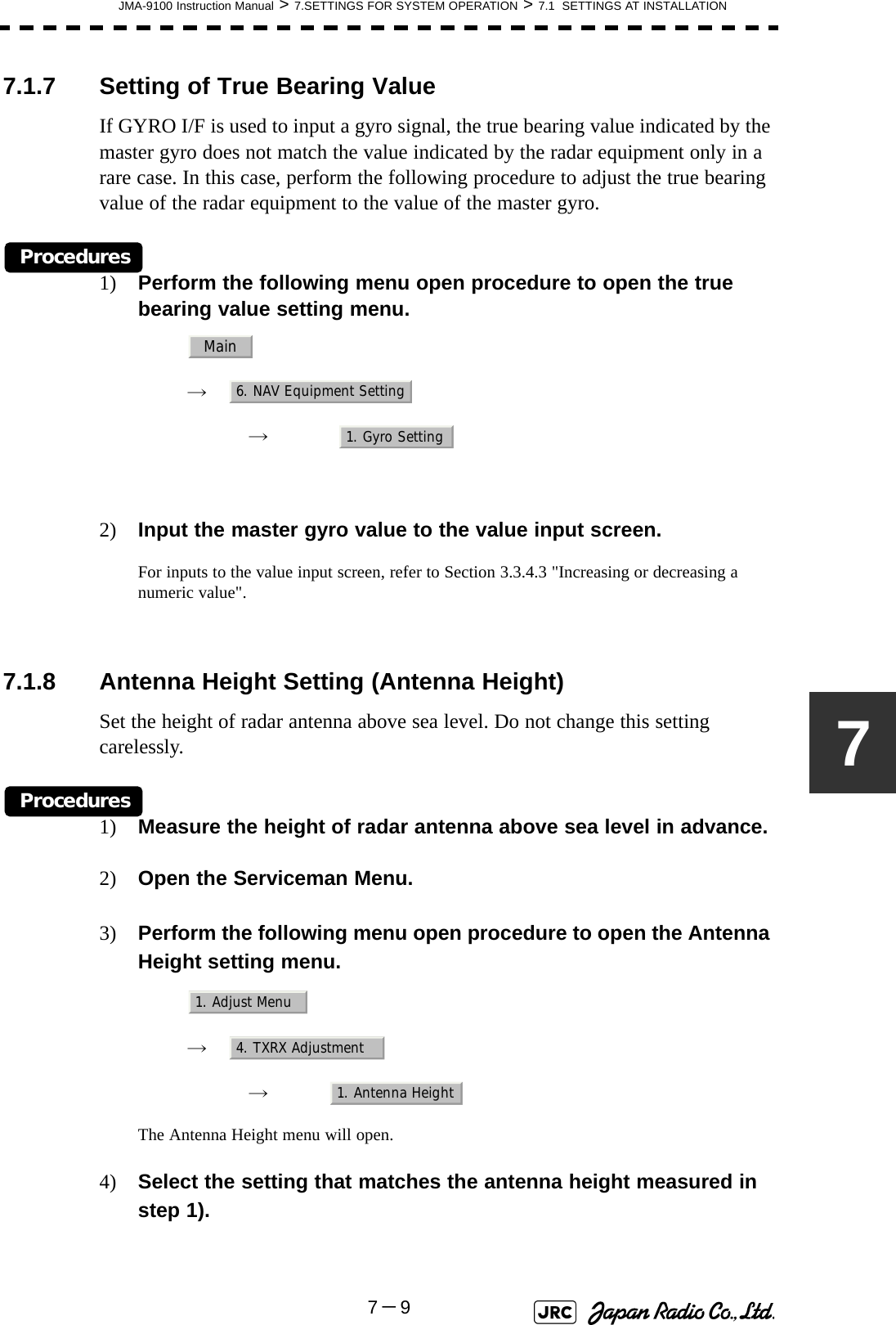
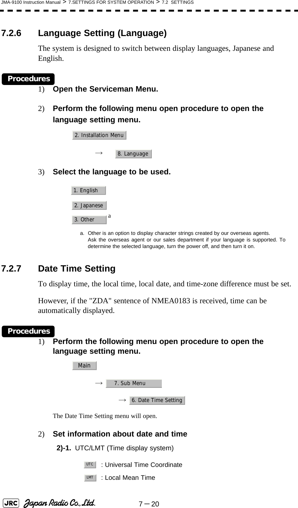
![JMA-9100 Instruction Manual > 5.OPERATION OF TARGET TRACKING AND AIS > 5.2 TARGET TRACKING OPERATION5-2555.2.7.4 Gate DisplayThe gate displays an area monitoring a target using the Target Tracking function. This radar equipment allows the gate size to change automatically according to target range and size. User can check the gate size using the following function.Procedures1) Open the TT Test Menu by performing the following menu operation.→ 2) Left-click the item button of .The gate display mode is switched.3) Display the numeric value of a target according to Section 5.2.3 "Tracked Target Data Display [TGT DATA]" .The numeric value of the target will be displayed, and the tracked target symbol will be enclosed in a green gate.: Gate is displayed: Gate is not displayediThe Target Tracking can display the gate of two targetssimultaneously.TT9. TT Test Menu4. Gate DisplayOnOffTracked Target symbolEcho Gate (displayed in green)Vector](https://usermanual.wiki/Japan-Radio/NKE1130.Users-Manual-2/User-Guide-994638-Page-17.png)
![5-26JMA-9100 Instruction Manual > 5.OPERATION OF TARGET TRACKING AND AIS > 5.3 AIS OPERATION5.3 AIS OPERATION5.3.1 RestrictionsThe following restrictions are placed on use of the AIS function.The AIS function is unavailable in the following cases:• or is selected for the speed sensor.The current offset (Set/Drift Setting) is set while or is selected for the speed sensor. or cannot be selected for the speed sensor in the following case:•The AIS function is turned on and the current offset (Set/Drift Setting) is selected. cannot be selected for the speed sensor in the following case:•The AIS function is On.Current offset (Set/Drift Setting) cannot be turned On in the following case:• or is selected for the speed sensor while the AIS function is on.5.3.2 Setting AIS Display Function (AIS Function) Procedures1) Press the [AIS/TT] key. Alternatively, left-click the button in the Target Information located at the upper right of the display.The received AIS information will be shown on the radar display. • When the AIS function is set to Off, the AIS display function is turned off and AIS symbols are no longer displayed.• Once the AIS display function is set to Off, it is not automatically switched to On even if a dangerous target exists.MANREF.LOG 2AXWLOG 2AXWMANLOG 2AXWAttentionAIS](https://usermanual.wiki/Japan-Radio/NKE1130.Users-Manual-2/User-Guide-994638-Page-18.png)
![JMA-9100 Instruction Manual > 5.OPERATION OF TARGET TRACKING AND AIS > 5.3 AIS OPERATION5-2755.3.3 Activate AIS Targets (Activate AIS)Activate an AIS target, and display the target’s vector and make a collision decision.5.3.3.1 Manual activation (ACT AIS)Activate an AIS target in manual mode to display the vector and heading line.Procedures1) Put the cursor on the AIS symbol to be activated, and right-click.The setting items for cursor modes will be displayed.2) Left-click .The selected AIS target will be activated.5.3.3.2 Automatic activationActivate an AIS target in automatic mode to display the vector and heading line.When the automatic activation function is used, AIS targets are automatically activated when they go into the automatic activation zone. The automatic activation zone is identical to the automatic acquisition zone (AZ) used for target tracking. For the zone setting, refer to Section 5.2.1 "Acquiring Target [ACQ]"The position of the scanner shall be at the centre of the azimuth or range in the acquisition/activation zone.If there are more AIS targets than the allowable maximum, they are deactivated in the low-priority (See the Section 5.1.2 "Definitions of Symbols").5.3.4 Deactivate AIS Targets (Deactivate AIS)Deactivate an AIS target and clear the display of the vector and heading line.Procedures1) Put the cursor on the AIS target to be deactivated, and right-click.The setting items for cursor modes will be displayed.2) Left-click The selected AIS target will be deactivated.iIf an AIS target is activated but the vector is not displayed, referto Section 5.3.6 "Displaying Target ID No. (Target NumberDisplay)".iThis operation is available only for an activated AIS target.2. ACT AIS5. DEACT AIS](https://usermanual.wiki/Japan-Radio/NKE1130.Users-Manual-2/User-Guide-994638-Page-19.png)
![5-28JMA-9100 Instruction Manual > 5.OPERATION OF TARGET TRACKING AND AIS > 5.3 AIS OPERATION5.3.5 Displaying AIS Information [TGT DATA] 5.3.5.1 Types of information displayedThere are two modes (simple and detail) to display AIS target information. The display items are determined by the selected mode.The detail mode displays the numeric data of only a single ship, the simple mode can display the numeric data of up to two ships.For NAV Status, one of the following statuses is displayed in accordance with Navigation Status:Display Item Detail mode Simple modeNAME (ship name) Up to 20 charactersCall Sign Up to 7 charactersMMSI Up to 9 charactersCOG (course over ground) or CTW (course through water) 0.1° unitSOG (speed over ground) or STW (speed through water) 0.1kn unitCPA (closest point of approach) 0.01NM unitTCPA (time to CPA) 0.1min unitBRG (true bearing) 0.1° unit Not displayedRange 0.01NM unitHDG (heading bearing) 0.1° unitROT (rate of turn) 0.01° /minPOSN (latitude / longitude) 0.001' unitDestination (waypoint) Up to 20 charactersNAV Status Status (number)No. Status0 Under Way Using Engine1at Anchor2 Not Under Command3 Restricted Manoeuvrability4 Constrained by Her Draft5 Moored6 Aground7 Engaged in Fishing8 Under Way Sailing9 Reserved10 Reserved11-14 Reserved15 Not Defined](https://usermanual.wiki/Japan-Radio/NKE1130.Users-Manual-2/User-Guide-994638-Page-20.png)
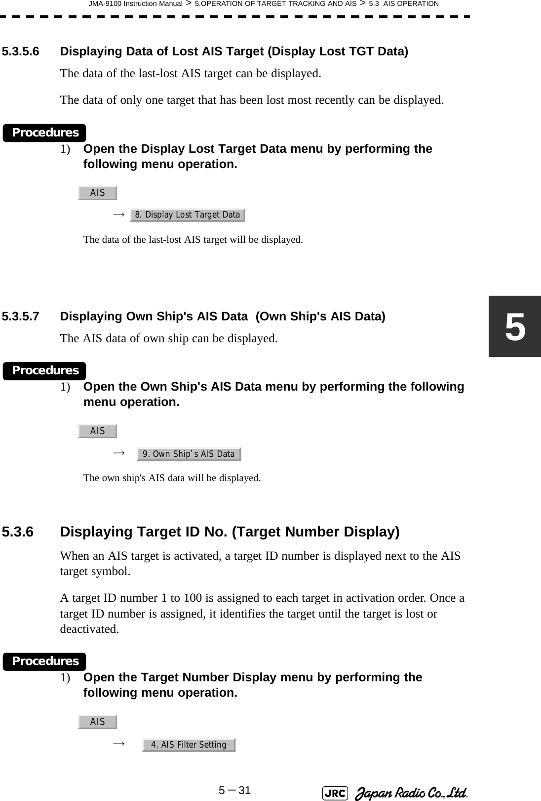
![JMA-9100 Instruction Manual > 5.OPERATION OF TARGET TRACKING AND AIS > 5.3 AIS OPERATION5-2955.3.5.2 Displaying AIS Target Information [TGT DATA] Procedures1) Put the cursor on the AIS target of which information is to be displayed , and press the [TGT DATA] key.The information of the selected AIS target will be displayed.5.3.5.3 Canceling AIS Target Information Display (CNCL Data)Procedures1) Put the cursor on the activated AIS target of which information display is to be cancelled, and right-click.The setting items for cursor modes will be displayed.2) Left-click .The information display of the selected AIS target will be cleared.5.3.5.4 Selecting Detail / Simple Mode for AIS Target Information DisplayProcedures1) Left-click the or button in the Digital Information located at the center right of the display.The detail or simple mode display for AIS target information will be selected. 5.3.5.5 MessageReceived AIS messages can be displayed.Up to 10 messages of addressed message and up to 10 messages of broadcast message can be displayed.If the number of messages exceeds 10, the oldest received messages are sequentially deleted.[1] Displaying Message Selected from List (Message)Procedures1) Open the Message menu by performing the following menu operation.iWhen the numeric data of a target is displayed but the mark is not on the radar display, the target is outside thedisplay.AIS126. CNCL Data□_](https://usermanual.wiki/Japan-Radio/NKE1130.Users-Manual-2/User-Guide-994638-Page-21.png)
![5-30JMA-9100 Instruction Manual > 5.OPERATION OF TARGET TRACKING AND AIS > 5.3 AIS OPERATION→ 2) Left-click or .Addressed messages list or broadcast messages list are displayed.Each list shows ship names and message-received time.For an unread message, is displayed to the left of the item number.3) Left-click the item button to display the message.The message will appear.[2] Displaying Specified Target's MessageProcedures1) Display AIS target information.If there are messages from the target, a message mark will be displayed in the Digital Information located at the center right of the display.2) Left-click the unread message display button in the Digital Information located at the center right of the display.The message will appear. [3] Deleting Message (Delete)Procedures1) Left-click while the message is displayed.The Confirmation Window will appear.2) Left-click to delete the message.The message will be deleted, and the ship name and message-received time will disappear from the list.AIS9. TT Test MenuAddressed Message Broadcast Message*1. Delete1. Yes](https://usermanual.wiki/Japan-Radio/NKE1130.Users-Manual-2/User-Guide-994638-Page-22.png)
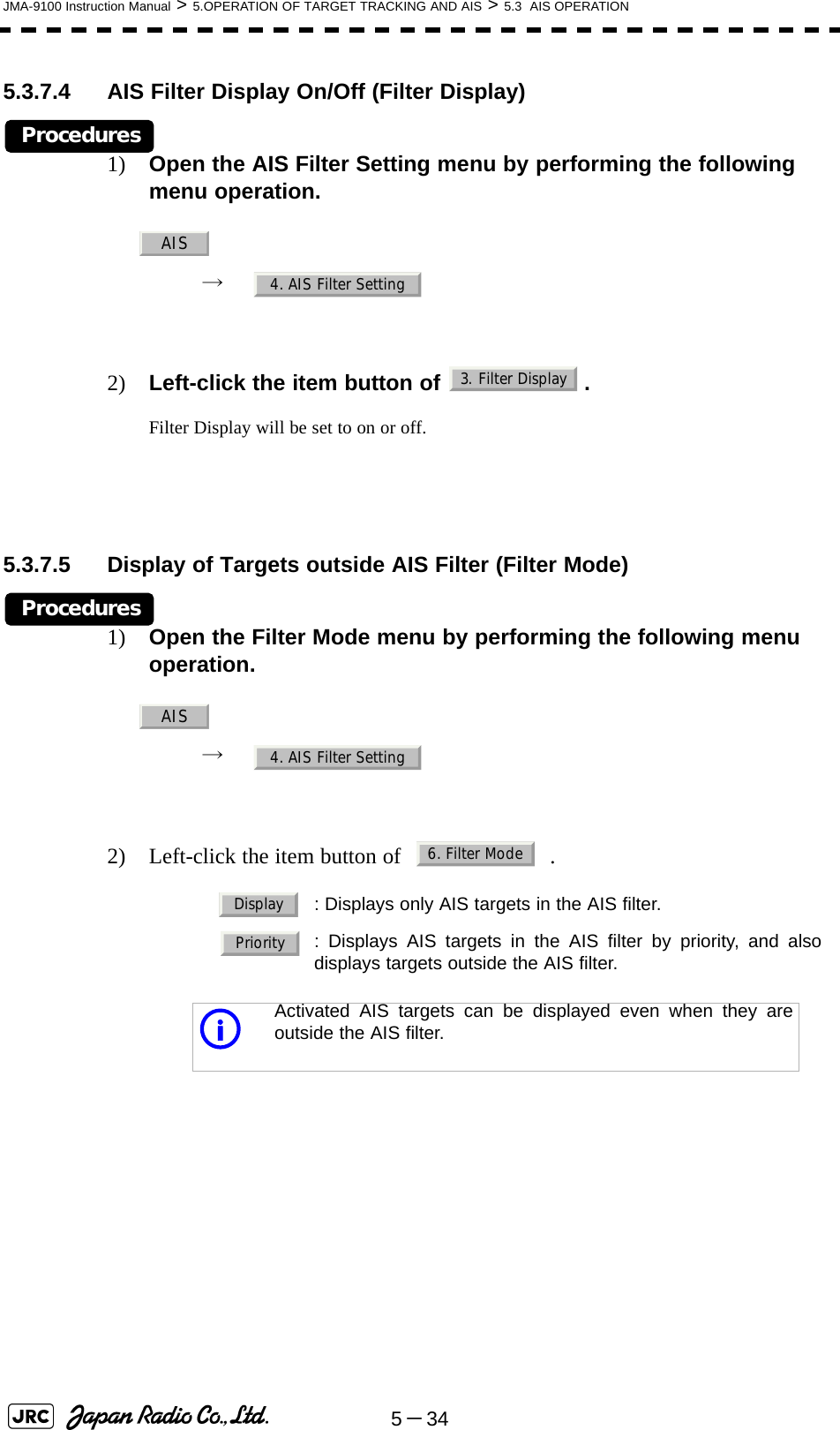
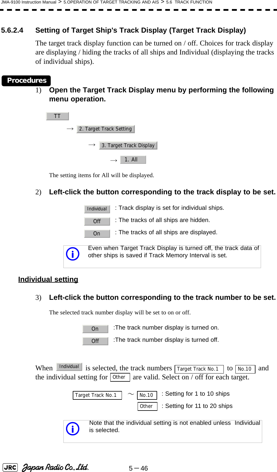
![5-32JMA-9100 Instruction Manual > 5.OPERATION OF TARGET TRACKING AND AIS > 5.3 AIS OPERATION2) Left-click the item button corresponding to the display method to be set.If there are many tracking targets and their symbol display is confusing, set Target Number Display to off to view the radar display easily. 5.3.7 Setting AIS Filter (AIS Filter Setting)5.3.7.1 About an AIS filterBy setting an AIS filter, an AIS target in the area can be displayed by priority or only the targets in the area can be displayed. An AIS filter is initially set in a circle having a radius of 20 [nm] from the CCRP. If 301 or more AIS targets exist in the filter range, they are displayed in the priority order explained in Section 5.1.2 "Definitions of Symbols".5.3.7.2 Types of AIS Filters (Filter Type)There are the following 3 types of AIS filters:Procedures1) Left-click the AIS filter mode switching in Target Information located at the upper right of the display, and select the filter to be set.The AIS filter will be selected.: Displays target ID numbers.: Hides target ID numbers.: Displays target ID number with AIS track.: Displays the ship's name.iAn ID number or ship's name is always displayed for onlytargets with which numeric value is displayed.: A filter is set in a circle with a set range as the radius. : A filter is set in a sector formed by two bearings with thebow as reference. : A filter is set in a zone formed by two bearings and tworanges with the bow as reference.OnOffTarget TrackShip’s NameRangeSectorZone](https://usermanual.wiki/Japan-Radio/NKE1130.Users-Manual-2/User-Guide-994638-Page-24.png)
![JMA-9100 Instruction Manual > 5.OPERATION OF TARGET TRACKING AND AIS > 5.3 AIS OPERATION5-3355.3.7.3 Creation of AIS Filter (Make AIS Filter)Procedures1) Open the AIS Filter Setting menu by performing the following menu operation.→ 2) Left-click .The mode to make an AIS filter will be activated.[1] Setting Range Filter3) Set a filter range by turning the [VRM] dial, and left-click.[2] Setting Sector Filter3) Set a starting bearing by turning the [EBL] dial, and left-click.4) Set an ending bearing by turning the [EBL] dial, and left-click. [3] Setting Zone Filter3) Set a starting bearing and range by turning the [EBL] dial and [VRM] dial, and left-click.4) Set an ending bearing and range by turning the [EBL] dial and [VRM] dial, and left-click.iWhen the automatic activation function is enabled, the filterrange is automatically changed for covering the automaticactivation zone. Thus, the automatic activation zone is alwayswithin the filter range.AIS4. AIS Filter Setting2. Make AIS Filter](https://usermanual.wiki/Japan-Radio/NKE1130.Users-Manual-2/User-Guide-994638-Page-25.png)
![JMA-9100 Instruction Manual > 5.OPERATION OF TARGET TRACKING AND AIS > 5.3 AIS OPERATION5-3555.3.7.6 Point FilterAIS targets which are not displayed because they are outside the AIS filter or at low priority levels can be activated by giving a higher priority to them.Procedures1) Put the cursor on the position where a point filter is to be set, and right-click to select the filter to be set.The setting items for cursor modes will be displayed.2) Left-click .A point filter will be set at the cursor position.If an AIS target is in the point filter, it will be activated.When an AIS target is activated or an AIS target is not found within one minute, the point filter will be cleared.5.3.8 Conditions for Deciding AIS Target to be LostAbout a lost targetWhen the data of an AIS target cannot be received for a specified time, the target is decided to be lost and the target data is deleted. As shown in the table below, the time until target data is deleted varies depending on the class of receive data and the target status.If the [ALARM ACK] key is pressed, the symbol is cleared. iThe point filter's range is 1 nm, and cannot be changed.Deciding AIS Target to be LostTarget status Time until data deletionSOLAS ship (Class A) SOLAS ship (Class B)Vessel below 3 knots (Class A) or 2 knots (Class B) and it is now at anchor or on the berth 18 min 18 minVessel of 3 knots or more and it is now at anchor or on the berth 60 sec 18 minVessel of 0 to 14 knots (Class B: 0 to 14 knots) 60 sec 180 secVessel of 14 to 23 knots 36 sec 180 secVessel of 23 knots or more 30 sec 180 seciWhen a dangerous target ship is lost, a lost alarm is issued andthe symbol changes to a lost symbol. The system calculatesthe current position from the last-received data and continuesdisplaying the symbol for eternity.2. ACT AIS](https://usermanual.wiki/Japan-Radio/NKE1130.Users-Manual-2/User-Guide-994638-Page-27.png)
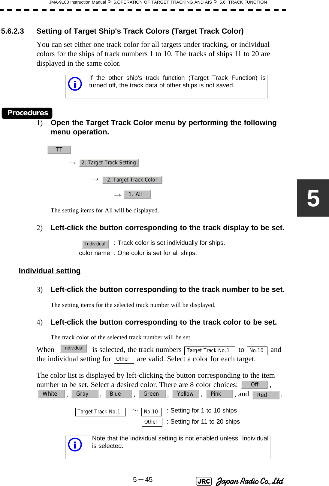
![JMA-9100 Instruction Manual > 5.OPERATION OF TARGET TRACKING AND AIS > 5.6 TRACK FUNCTION5-4755.6.2.5 Setting of Target Ship's Track Saving Interval (Track Memory Interval)An interval for saving target ship's track data can be set.Procedures1) Open the Track Memory Interval menu by performing the following menu operation.→ → 2) Left-click the button corresponding to the interval to be set.Select an interval from the following: 5.6.2.6 Clear of Target Ship's Track (Clear Track)The target ship's track can be cleared by setting a color or a track number.[1] Clear of Tracks by Setting Color (Clear Track Color)Procedures1) Open the Clear Track Color menu by performing the following menu operation.→ → The setting items for Clear Track Color will be displayed.iThis function is not available when the Target Track Function isturned off.Off/3sec/5sec/10sec/30sec/1min/3min/5min/10min/30min/60min/1NM/3NM/5NM/10NMiIf Card T.TRK Display is used, target ship's tracks displayedthrough the card cannot be cleared.TT2. Target Track Setting4. Track Memory IntervalTT2. Target Track Setting5. Clear Track Color](https://usermanual.wiki/Japan-Radio/NKE1130.Users-Manual-2/User-Guide-994638-Page-39.png)
![5-48JMA-9100 Instruction Manual > 5.OPERATION OF TARGET TRACKING AND AIS > 5.6 TRACK FUNCTION2) Left-click the button corresponding to the color of the target tracks to be cleared.The Confirmation Window will appear.3) Left-click to clear the track line.All the tracks of the selected color will be cleared.[2] Clear of Tracks by Setting Track Number (Clear Track Number)Procedures1) Open the T.TRK menu by performing the following menu operation.→ → The setting items for Clear Track Number will be displayed.2) Left-click the button corresponding to the number of the tracks to be cleared.The Confirmation Window will appear.3) Left-click to clear the track line.The tracks of the selected number will be cleared. 5.6.2.7 Operation of Target Ship's Track Data Saved on Card (FileOperations)Target ship's track data can be saved on a flash memory card and read from the card.[1] Loading File (Load)Procedures1) Insert a flash memory card into the card slotFlash memory card (option) is necessary.iData can be saved to a flash memory card until the cardbecomes full, but the number of files that can be read anddisplayed is limited to 64 in alphanumeric order. When thenumber of files has reached 64, delete unnecessary files.1. YesTT2. Target Track Setting6. Clear Track Number1. Yes](https://usermanual.wiki/Japan-Radio/NKE1130.Users-Manual-2/User-Guide-994638-Page-40.png)
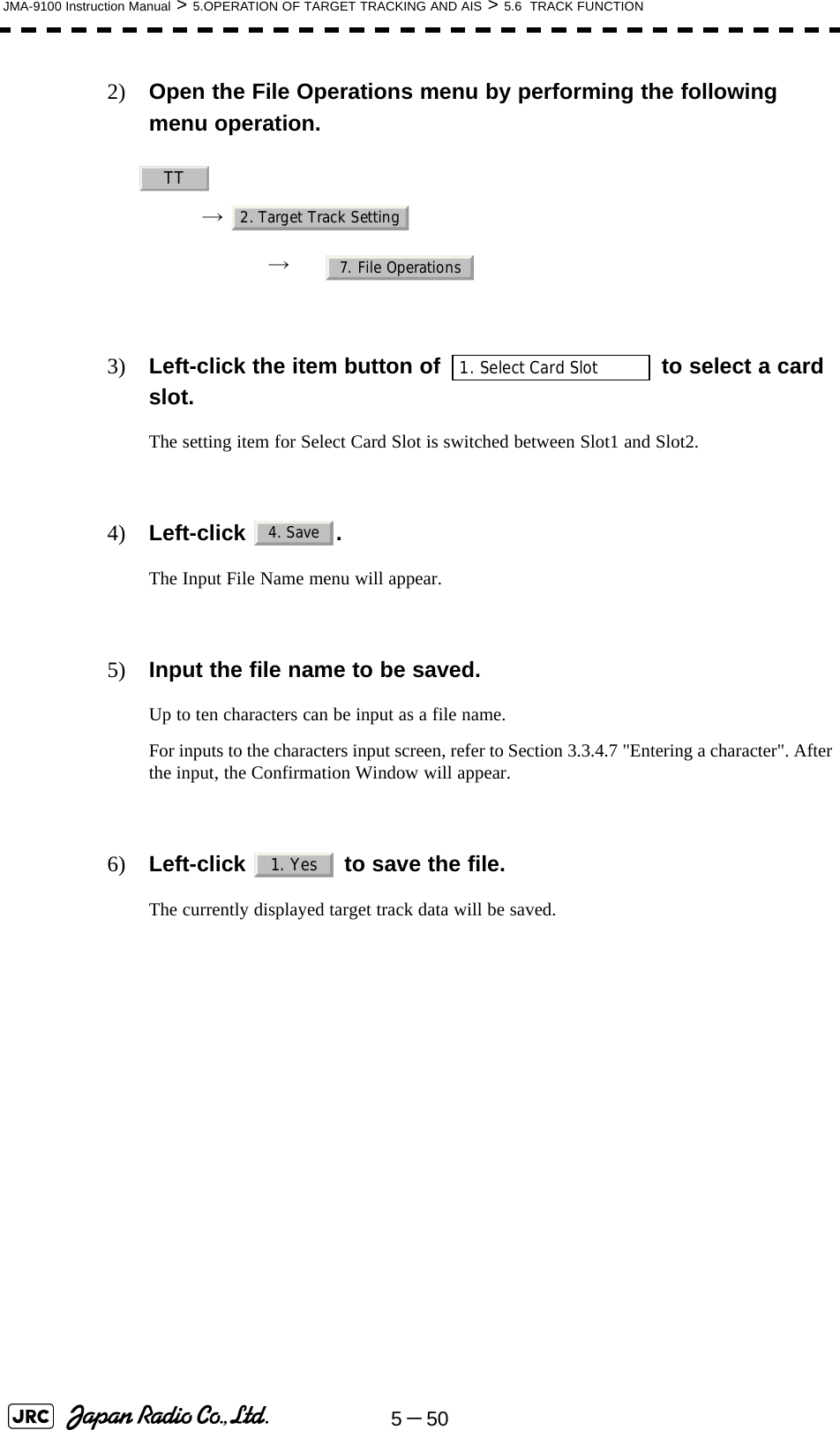
![JMA-9100 Instruction Manual > 5.OPERATION OF TARGET TRACKING AND AIS > 5.6 TRACK FUNCTION5-4952) Open the File Operations menu by performing the following menu operation.→ → 3) Left-click the item button of to select a card slot.The setting item for Select Card Slot is switched between Slot1 and Slot2.4) Left-click the item button of to select Add or Overwrite. The setting item for Load Mode is switched between and .When is selected, new data is added to the current data on the card. When is selected, new data is saved over the current data on the card.5) Left-click .Currently saved target ship's track data will be listed.6) Left-click the button corresponding to the file to be loaded.The Confirmation Window will appear.7) Left-click to load the file.The selected target track data will be loaded and shown on the radar display.[2] Saving File (Save)Procedures1) Insert a flash memory card into the card slot.Flash memory card (option) is necessary.TT2. Target Track Setting7. File Operations1. Select Card Slot2. Load ModeAddOverwriteAddOverwrite3. Load1. Yes](https://usermanual.wiki/Japan-Radio/NKE1130.Users-Manual-2/User-Guide-994638-Page-41.png)
![JMA-9100 Instruction Manual > 5.OPERATION OF TARGET TRACKING AND AIS > 5.6 TRACK FUNCTION5-515[3] Erasing File (Erase)Procedures1) Insert the flash memory card into the card slot.Flash memory card (option) is necessary.2) Open the File Operations menu by performing the following menu operation.→ → 3) Left-click the item button of to select a card slot.The setting item for Select Card Slot is switched between Slot1 and Slot2.4) Left-click .The Erase menu will appear.Currently saved target ship's track data on the card will be listed.5) Left-click the button corresponding to the file to be erased.The Confirmation Window will appear.6) Left-click to erase the file.The selected target track data will be erased and the file name will disappear from the list.TT2. Target Track Setting7. File Operations1. Select Card Slot5. Erase1. Yes](https://usermanual.wiki/Japan-Radio/NKE1130.Users-Manual-2/User-Guide-994638-Page-43.png)
![5-52JMA-9100 Instruction Manual > 5.OPERATION OF TARGET TRACKING AND AIS > 5.6 TRACK FUNCTION[4] Displaying File (Card Target Track Display)Procedures1) Insert the flash memory card into the card slot.Flash memory card (option) is necessary.2) Open the File Operations menu by performing the following menu operation.→ → 3) Left-click the item button of to select a card slot. The setting item for Select Card Slot is switched between Slot1 and Slot2.4) Left-click . The Card T.TRK Display menu will appear.Currently saved target ship's track data on the card will be listed.5) Left-click the button corresponding to the file to be displayed.The Confirmation Window will appear.6) Left-click to display the T.TRK line.The selected file will be highlighted, and the currently saved target track data will be displayed.Cancel1) Open the Card T.TRK Display window.The displayed file is highlighted.2) Left-click the button corresponding to the displayed file.The file will be deselected and returned to normal display.TT2. Target Track Setting7. File Operations1. Select Card Slot6. Card T.TRK Display1. Yes](https://usermanual.wiki/Japan-Radio/NKE1130.Users-Manual-2/User-Guide-994638-Page-44.png)
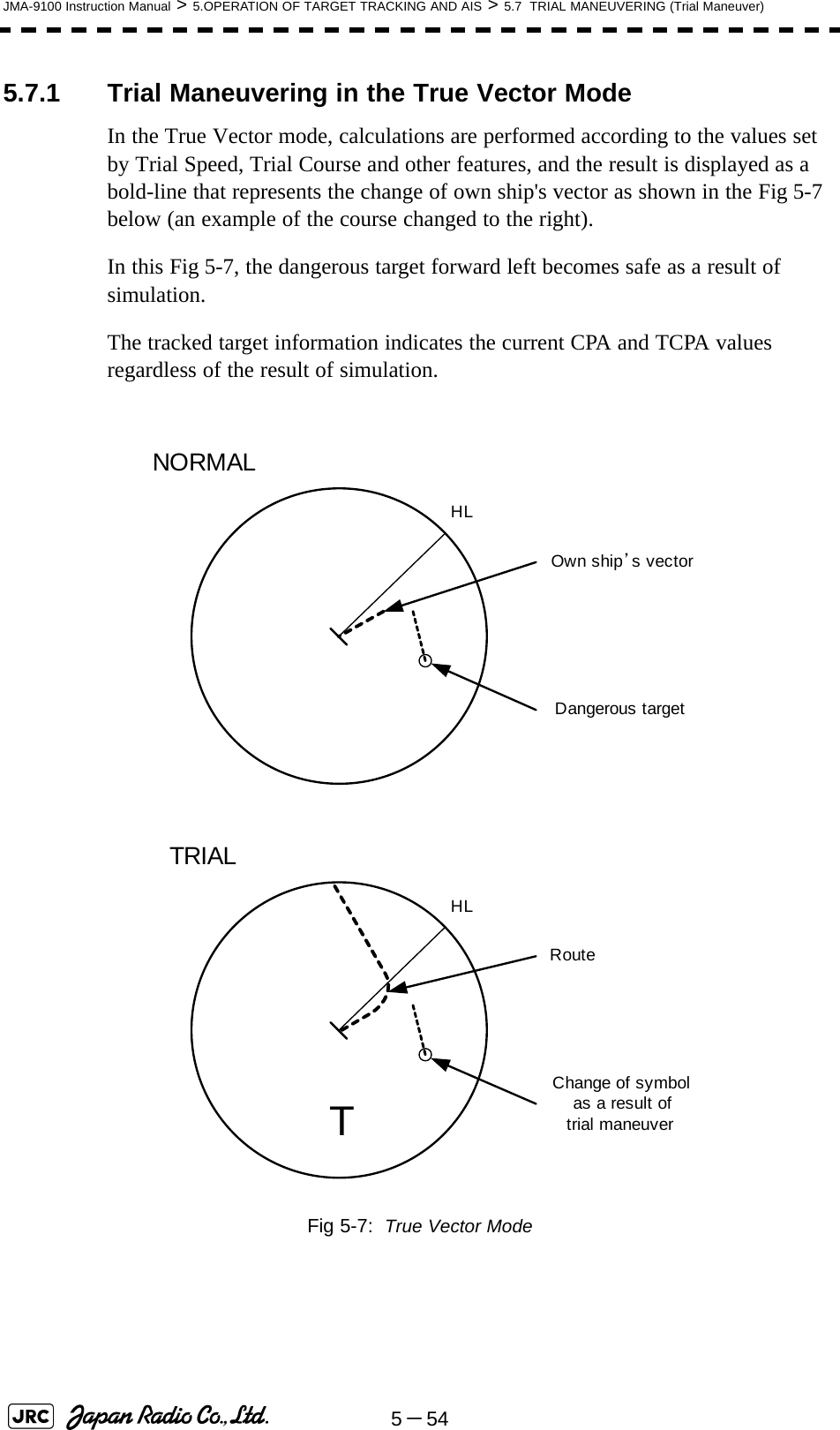
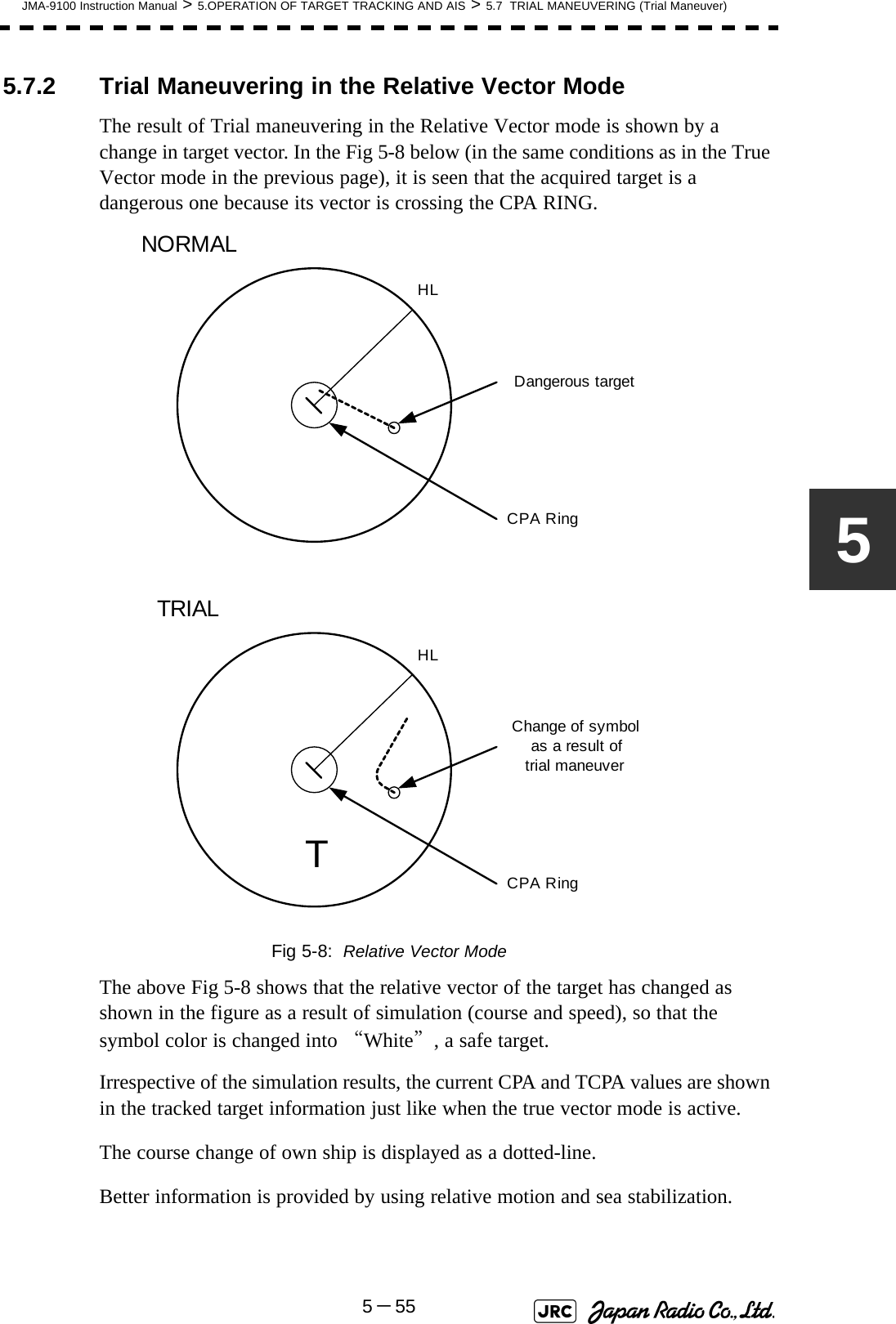
![JMA-9100 Instruction Manual > 5.OPERATION OF TARGET TRACKING AND AIS > 5.7 TRIAL MANEUVERING (Trial Maneuver)5-5355.7 TRIAL MANEUVERING (Trial Maneuver) The trial maneuvering is the function of simulating own ship’s course and speed for collision avoidance when a dangerous target appears. When the own ship's course and speed are entered in manual mode, the trial maneuvering function checks if pre-acquired or pre-activated targets are dangerous.The ranges of course and speed to be entered manually:• Trial maneuvering is to simulate own ship’s course and speed in the conditions that the course and speed of a target ship are unchanged as they are. As the situation is different from any actual ship maneuvering, set values with large margins to CPA Limit and TCPA Limit.Course: 360° (in 0.1° intervals) ............................................... [EBL] dialSpeed: 0 to 100kn (in 0.1kn step)........................................ [VRM] dialAttention](https://usermanual.wiki/Japan-Radio/NKE1130.Users-Manual-2/User-Guide-994638-Page-45.png)
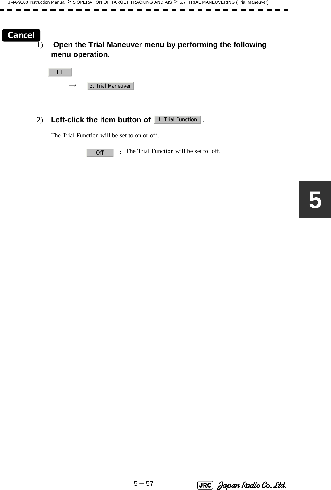
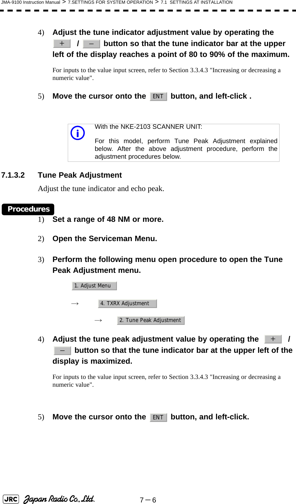
![5-56JMA-9100 Instruction Manual > 5.OPERATION OF TARGET TRACKING AND AIS > 5.7 TRIAL MANEUVERING (Trial Maneuver)5.7.3 Operation of Trial Maneuvering FunctionProcedures1) Open the Trial Maneuver menu by performing the following menu operation.→ 2) Left-click the item button of .The Trial Function will be set to on or off.When Trial Function is set to on, the character " T " indicating trial maneuvering blinks in the own ship display field of the radar display.3) Set values for Course by turning the [EBL] dial, and for Speed by turning the [VRM] dial.4) Set other characteristics.For inputs to the value input screen, refer to Section 3.3.4.2 "Directly entering a numeric value".Dangerous target symbols are displayed in red and safe target symbols in white.: The trial maneuvering function is turned on.: The trial maneuvering function is turned off.: Vector time (1 to 60 min): Time until trial maneuvering is started (0 to 30 min): Dynamic trait of the own ship→ : Range from when steered to when the shipbeings to turn (0 to 2000 m)→ : Turning radius (0.10 to 2.00 nm)→ : Acceleration (0.0 to 100 knots/min)→ : Deceleration (0.0 to 100 knots/min)iVector Time is valid only when Trial Function is set to on. If it is off, the vector timebefore trial maneuvering is displayed.Time until the start of trial maneuvering is counted down immediately after the input.The acceleration and deceleration are influenced depending on the relationshipbetween the current speed and the input speed for trial maneuvering.If 0.0 kn/min is set for Acceleration when the speed for trial maneuvering is fasterthan the current speed, or for Deceleration when the speed for trial maneuvering isslower than the current speed, the system performs simulation on the assumptionthat the speed is changed immediately after the time set for Time to Maneuver .TT3. Trial Maneuver1. Trial FunctionOnOffVector TimeTime to ManeuverOwn Ship Dynamic TraitReachTurn RadiusAccelerationDecceleration](https://usermanual.wiki/Japan-Radio/NKE1130.Users-Manual-2/User-Guide-994638-Page-48.png)

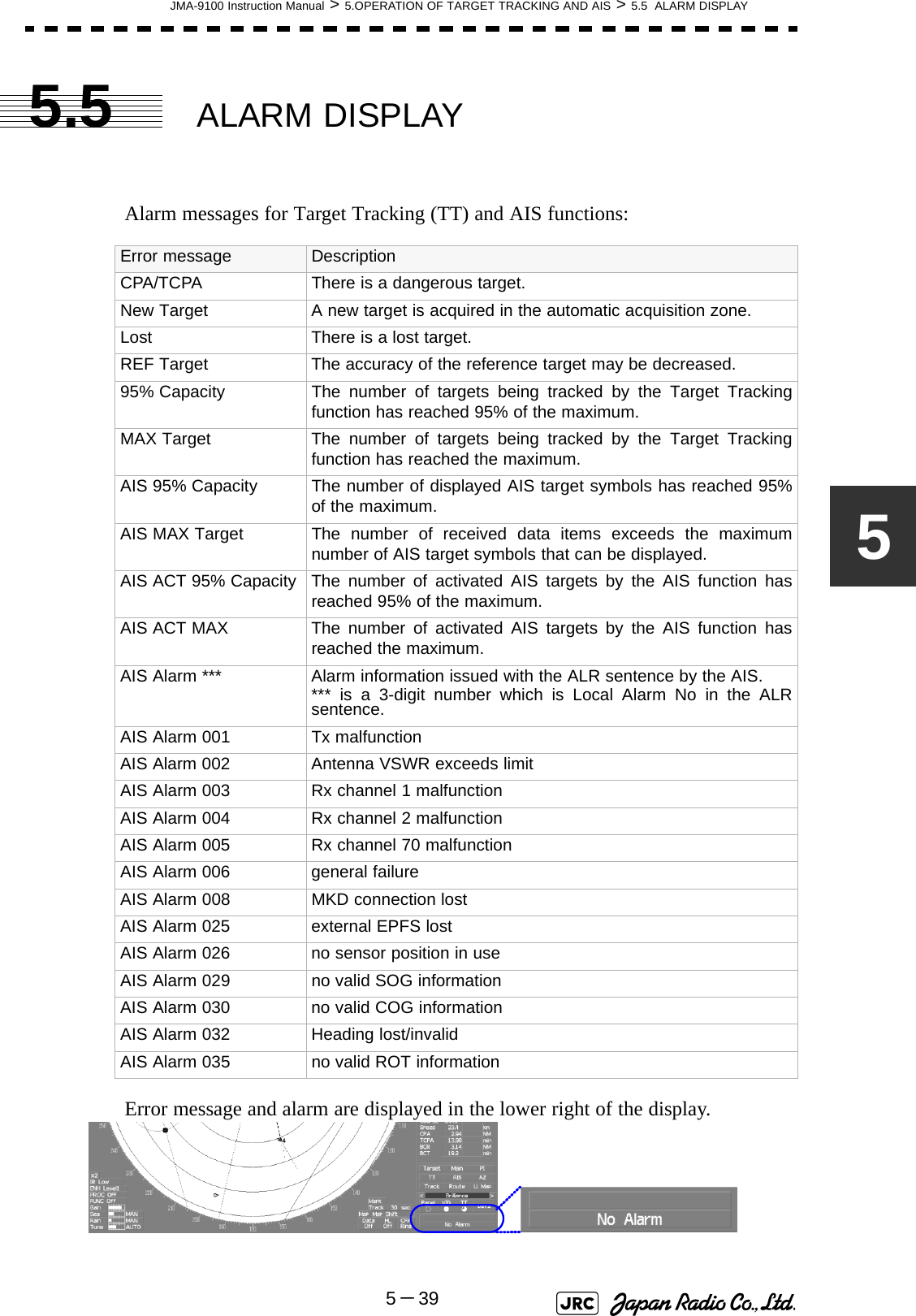
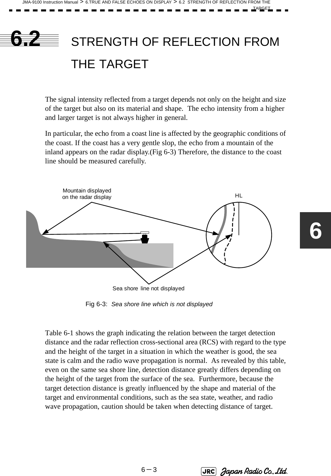
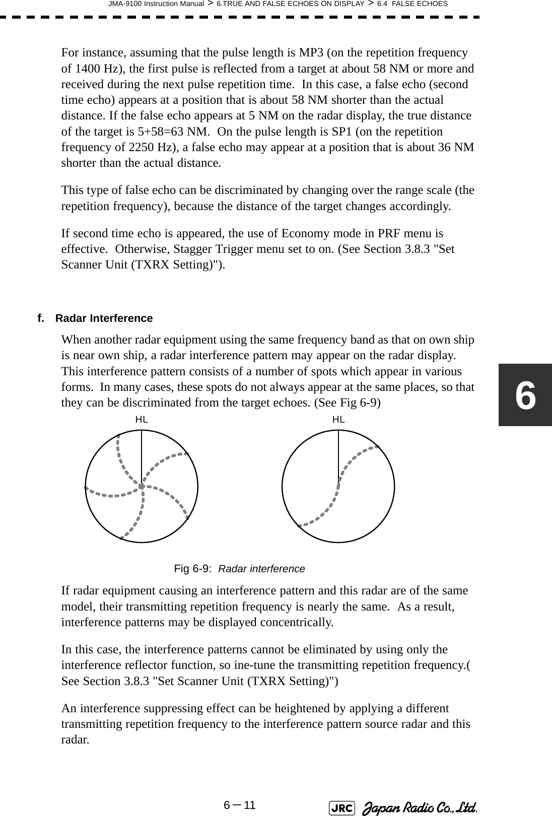
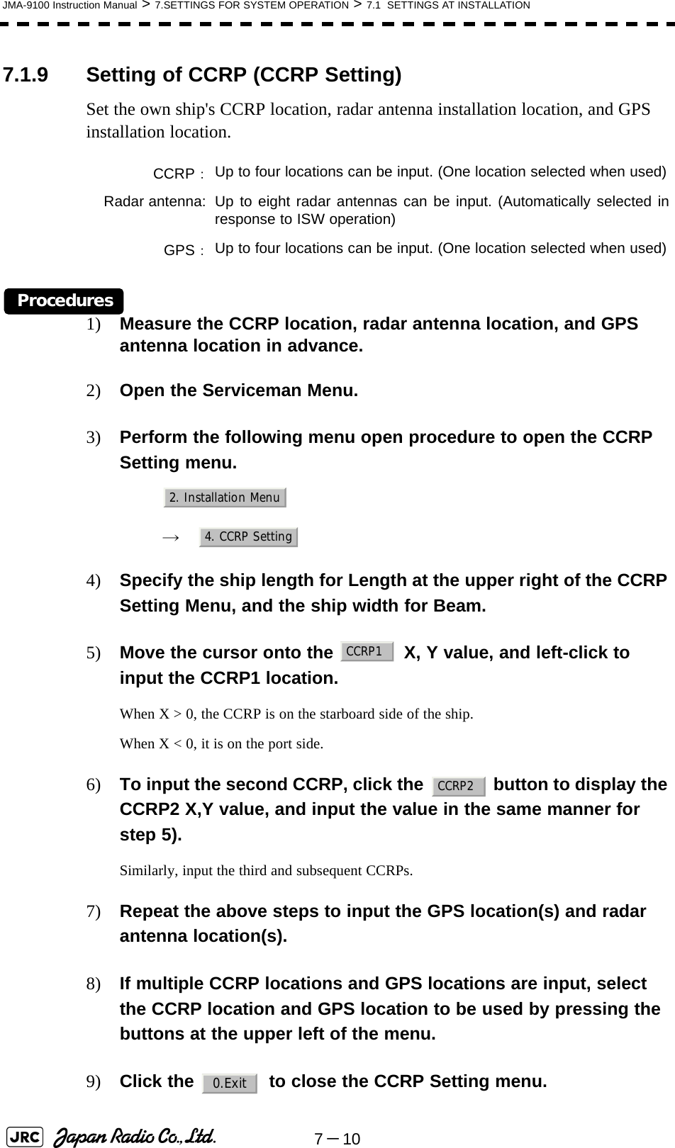
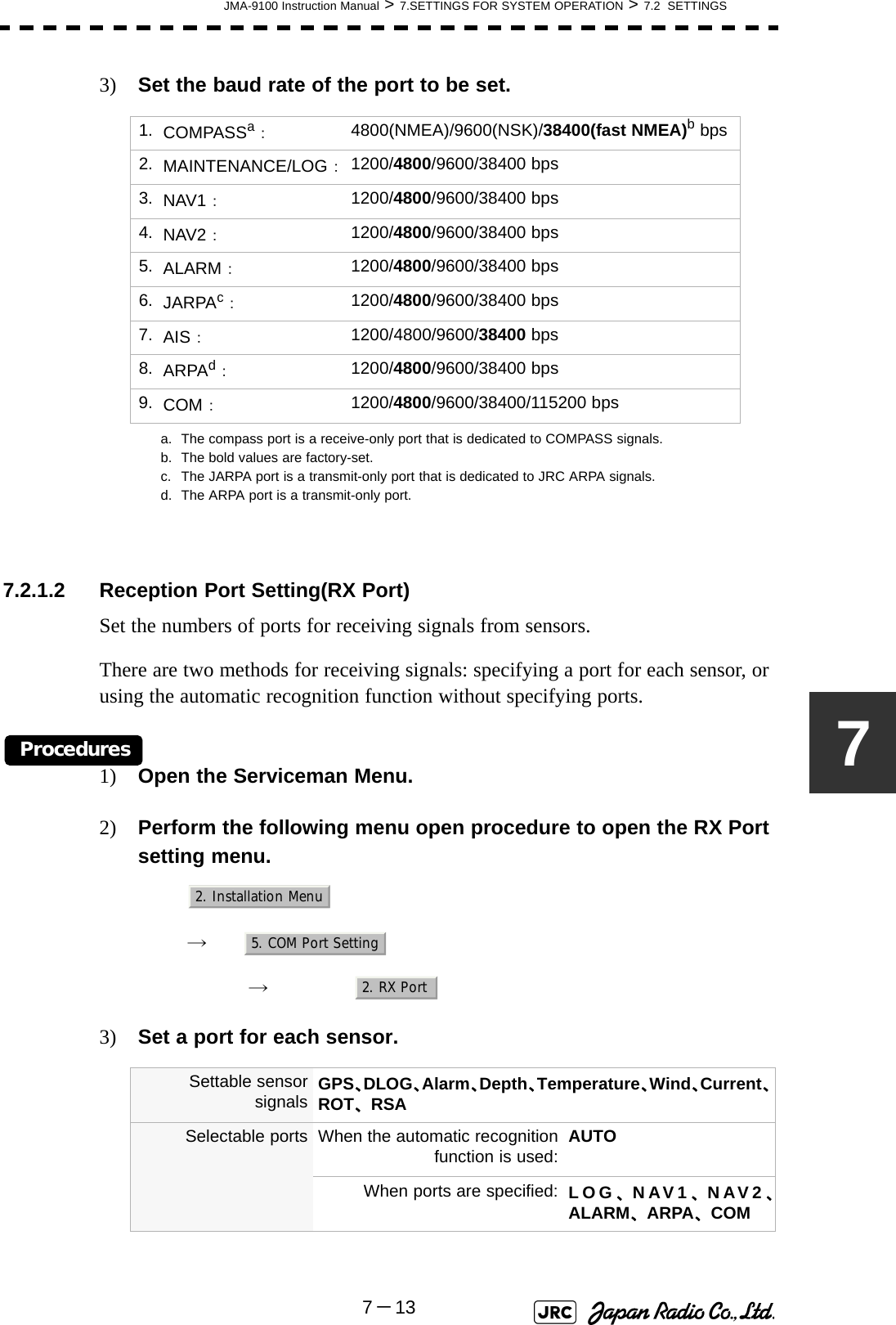
![JMA-9100 Instruction Manual > 6.TRUE AND FALSE ECHOES ON DISPLAY > 6.1 RADAR WAVE WITH THE HORIZON6-16The radar operator has a role of interpreting the radar displays to provide his best aid in maneuvering the ship. For this purpose, the operator has to observe the radar displays after fully understanding the advantages and disadvantages that the radar has. For better interpretation of radar display, it is important to gain more experiences by operating the radar equipment in fair weathers and comparing the target ships watched with the naked eyes and their echoes on the radar display.The radar is mainly used to monitor the courses of own ship and other ships in open seas, to check buoys and other nautical marks when entering a port, to measure own ship’s position in the coastal waters relative to the bearings and ranges of the shore or islands using a chart, and to monitor the position and movement of a heavy rain if it appears on the radar display.Various types of radar display will be explained below.6.1 RADAR WAVE WITH THE HORIZONRadar beam radiation has the nature of propagating nearly along the curved surface of the earth. The propagation varies with the property of the air layer through which the radar beam propagates. In the normal propagation, the distance (D) of the radar wave to the horizon is approximately 10% longer than the distance to the optical horizon. The distance (D) is given by the following formula: [NM]: Height (m) of radar scanner above sea level: Height (m) of a target above sea levelFig 6-2 is a diagram for determining the maximum detection range of a target that is limited by the curve of the earth surface in the normal propagation.Fig 6-1: RADAR wave with the horizonD2.23h1h2+()=h1h2DEarthh1h2Radar Targets](https://usermanual.wiki/Japan-Radio/NKE1130.Users-Manual-2/User-Guide-994638-Page-53.png)
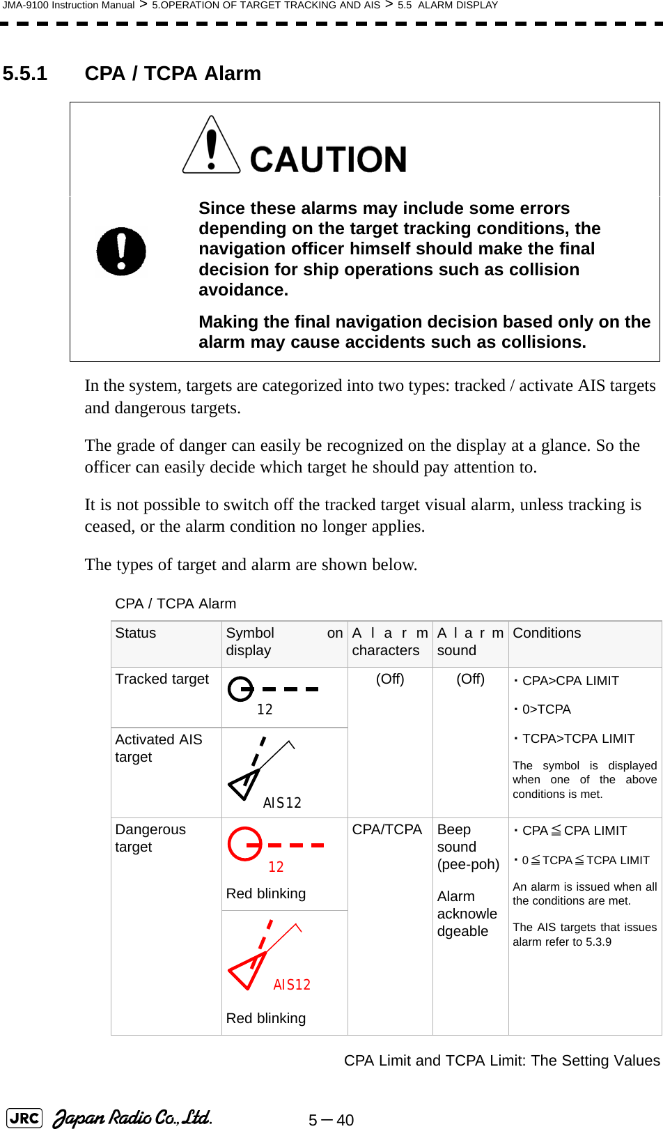
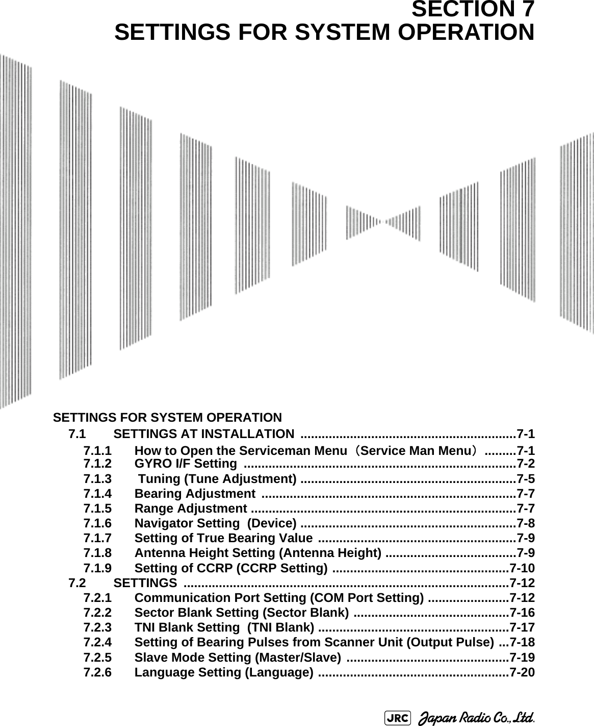
![6-2JMA-9100 Instruction Manual > 6.TRUE AND FALSE ECHOES ON DISPLAY > 6.1 RADAR WAVE WITH THE HORIZON Fig 6-2: Maximum detection range of a targetWhen the height of own ship’s scanner is 10 m for instance,i. A target that can be detected at the radar range of 64 nm on the radar displayis required to have a height of 660 m or more.ii. If the height of a target is 10 m, the radar range has to be approx. 15 nm.However, the maximum radar range at which a target can be detected on theradar display depends upon the size of the target and the weather conditions,that is, the radar range may increase or decrease depending upon thoseconditions. Height of RADAR Scanner Detective Range Height of TargetD[NM]](https://usermanual.wiki/Japan-Radio/NKE1130.Users-Manual-2/User-Guide-994638-Page-54.png)
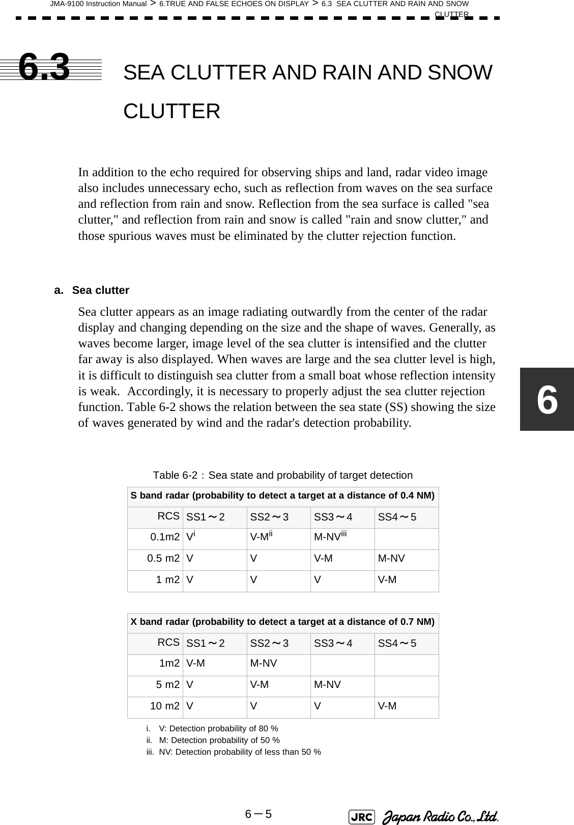
![6-4JMA-9100 Instruction Manual > 6.TRUE AND FALSE ECHOES ON DISPLAY > 6.2 STRENGTH OF REFLECTION FROM THE TARGET Table 6-1: Relation between type and height of target and detection distance and RCSType of target Height from sea surface (m)Detection distance (NM) RCS X band S band X band S bandSea shore line 60 20 20 50,000 50,000Sea shore line 6 8 8 5000 5000Sea shore line 3 6 6 2500 2500SOLAS target ship (>5000GT) 10 11 11 50,000 30,000SOLAS target ship (>500GT) 5 8 8 1800 1000Small boat with IMO standard compatible radar reflector 45.03.77,50,5Marine buoy with corner reflector 3,5 4.9 3.6 10 1Standard marine buoy 3,5 4.6 3.0 5 0,510-meter small boat without radar reflector 23.43.02,51,4Waterway location beacon 1 2.0 1.0 1 0,1Detection distance shown in the above table may greatlydecrease depending on the shape of the target, sea state,weather and radio wave propagation conditions.m2[]i](https://usermanual.wiki/Japan-Radio/NKE1130.Users-Manual-2/User-Guide-994638-Page-56.png)
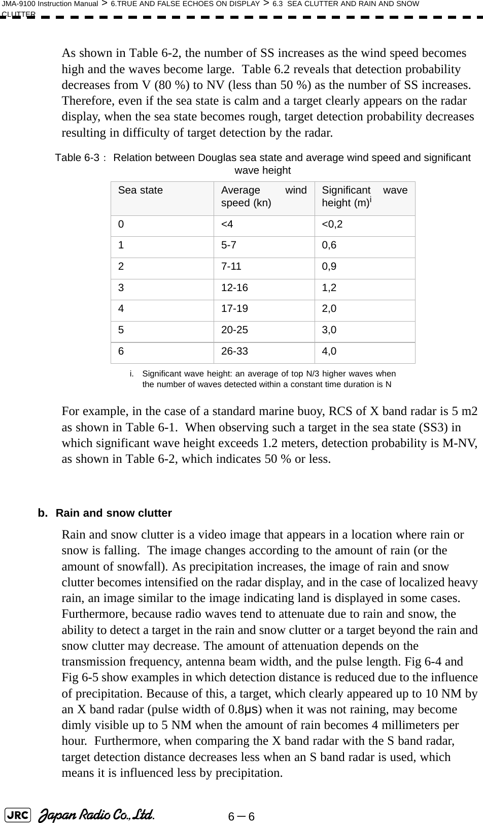
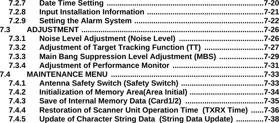
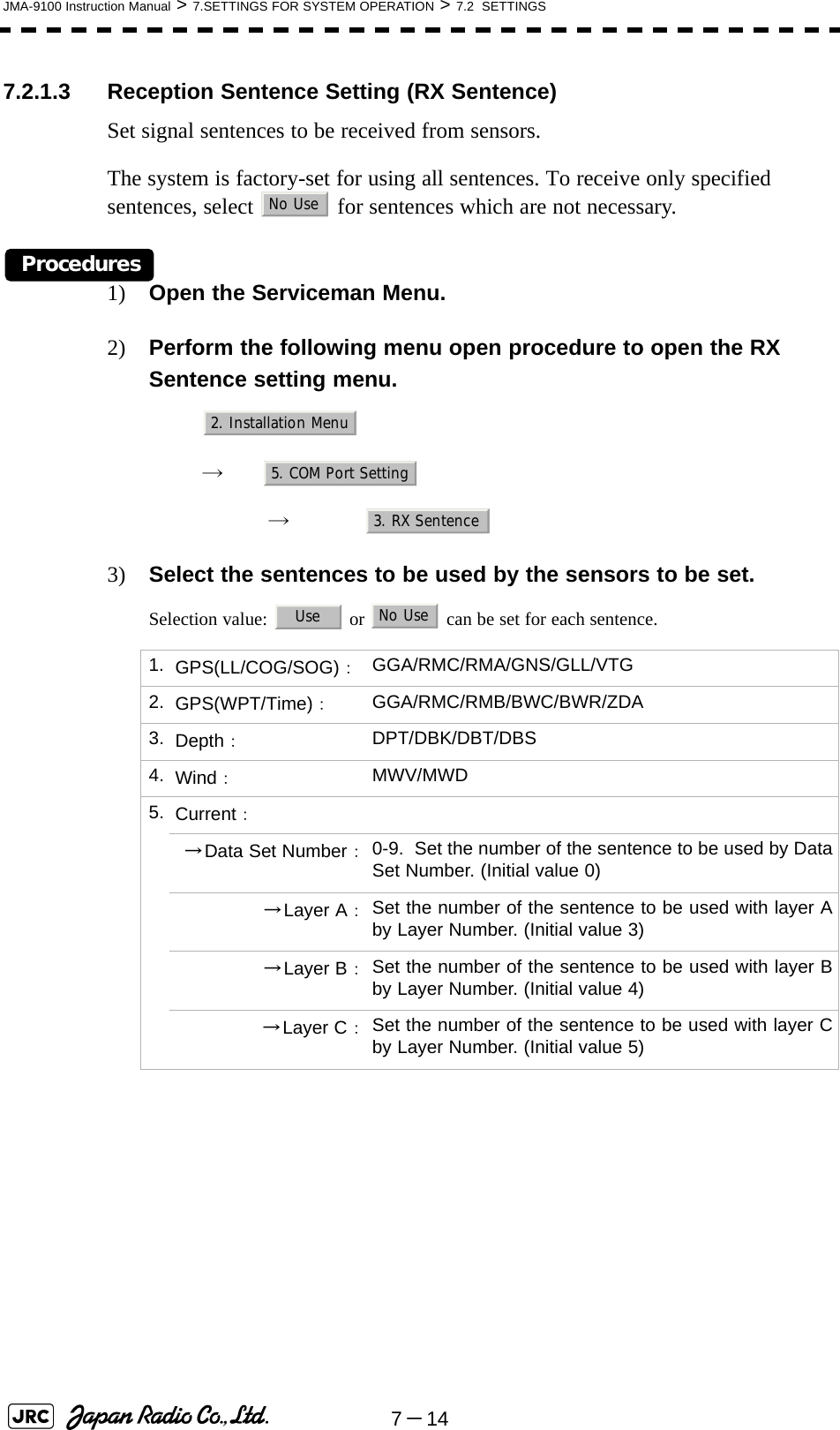
![JMA-9100 Instruction Manual > 6.TRUE AND FALSE ECHOES ON DISPLAY > 6.3 SEA CLUTTER AND RAIN AND SNOWCLUTTER6-76 02468101214160 2 4 6 81012 14 16降雨時の検出距離 (NM) 雨の降っていないときの検出距離(NM) 16mm/hr の降雨時 パルス幅 0.05us4mm/hr の降雨時 パルス幅 0.05us16mm/hr の降雨時 パルス幅 0.8us4mm/hr の降雨時 パルス幅 0.8usDetection distance while it is not rainning[NM]Detection distance while it is raining [NM]Precipitation of 16 mm/hr Pulse width 0.8usPrecipitation of 4 mm/hr Pulse width 0.8usPrecipitation of 4 mm/hr Pulse width 0.05usPrecipitation of 16 mm/hr Pulse width 0.05usFig 6-4: Decreased target detection distance by S band radar due to precipitation 0 2 4 6 8 10 12 14 16 024 6810 12 14 16降雨時の検出距離 (NM) 16mm/hr の降雨時 パルス幅 0.05us4mm/hr の降雨時 パルス幅 0.05us16mm/hr の降雨時 パルス幅 0.8us4mm/hr の降雨時 パルス幅 0.8us雨の降っていないときの検出距離(NM) Detection distance while it is not rainning[NM]Detection distance while it is raining [NM]Precipitation of 16 mm/hr Pulse width 0.8usPrecipitation of 4 mm/hr Pulse width 0.8usPrecipitation of 4 mm/hr Pulse width 0.05usPrecipitation of 16 mm/hr Pulse width 0.05usFig 6-5: Decreased target detection distance by X band radar due to precipitation](https://usermanual.wiki/Japan-Radio/NKE1130.Users-Manual-2/User-Guide-994638-Page-59.png)
![6-8JMA-9100 Instruction Manual > 6.TRUE AND FALSE ECHOES ON DISPLAY > 6.3 SEA CLUTTER AND RAIN AND SNOW CLUTTERc. Coping with sea clutter and rain and snow clutterWhen the weather is bad and the ocean is rough, the use of an S band radar is effective because the radar is not influenced by sea clutter so much and attenuation due to rain drops is small. When an X band radar is used, reducing the pulse width will reduce the influence by spurious waves, and also the spurious wave rejection function effectively works; therefore, the use of short pulse is effective when the weather is bad. By using image processing functions PROCl 1 to 3, it is expected that spurious waves are further suppressed. Since optimal settings for those items can be automatically made by using the function mode, it is recommended that STORM or RAIN be used by selecting the function mode when the weather is bad. For details of the function mode, see Section 3.9 "USE FUNCTION KEY [USER]".However, these functions may make some targets invisible, particularly targets with higher speeds.](https://usermanual.wiki/Japan-Radio/NKE1130.Users-Manual-2/User-Guide-994638-Page-60.png)
![6-12JMA-9100 Instruction Manual > 6.TRUE AND FALSE ECHOES ON DISPLAY > 6.5 DISPLAY OF RADAR TRANSPONDER (SART)6.5 DISPLAY OF RADAR TRANSPONDER (SART)The SART (Search and rescue Radar Transponder) is a survival device authorized by the GMDSS (Global Maritime Distress and Safety System), which is used for locating survivors in case that a distress accident occurs at sea. The SART is designed to operate in the 9 GHz frequency band.When receiving the 9 GHz radar signal (interrogating signal) transmitted from the radar equipment on a rescue ship or search aircraft, the SART transmit a series of response signals to inform the distress position to the rescue and search party.Procedures1) Press [RANGE +] or [RANGE -] key to set the radar range to 6 NM or 12 NM.2) Set the SART display mode according to the procedures below. → → → With the SART display mode set to ON, settings as shown below are made automatically.This radar provides a shortcut item to make settings for SARTsignal reception. Execution of this item automatically switchesto the setting for SART reception.It also functions for detect thebeacon or target enhancer. :SART ON :SART OFFSea clutter control : Minimum (Most counterclockwise)AUTO SEA function : OFFRain and Snow Clutter Control (RAIN) : MinimumAuto Rain and Snow Clutter function(AUTO RAIN) :OFFTUNE control : No tuning (to weaken clutterechoes)Interference rejection (IR) : OFFPROCESS : OFFiMain3. RADAR Menu1. Process Setting9. SARTOnOff](https://usermanual.wiki/Japan-Radio/NKE1130.Users-Manual-2/User-Guide-994638-Page-64.png)
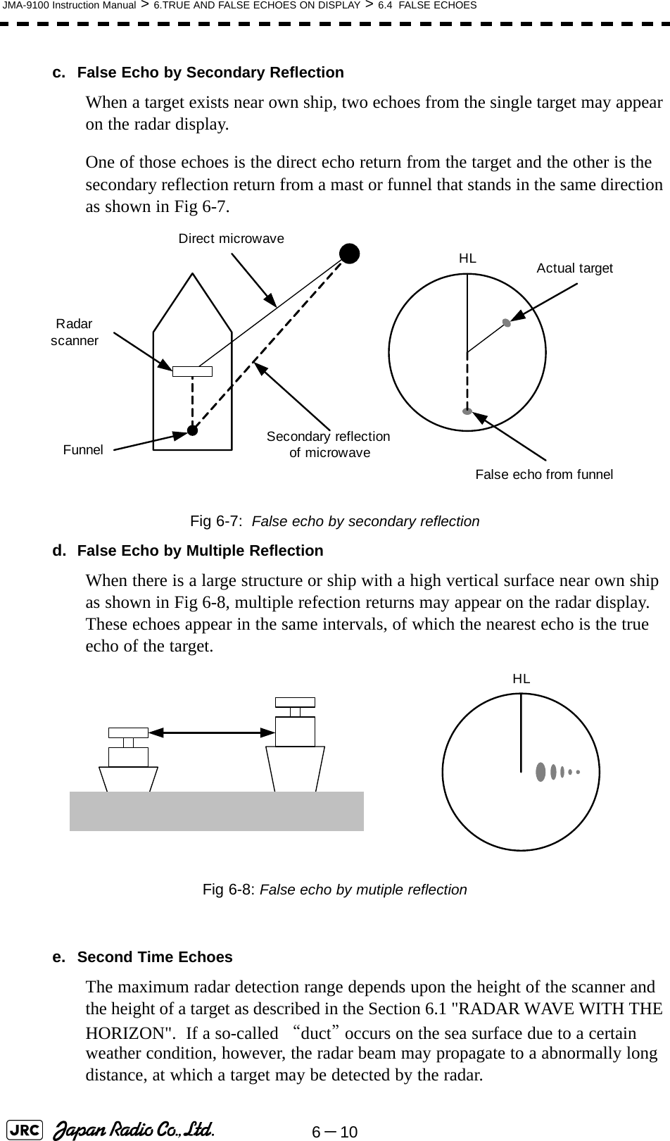
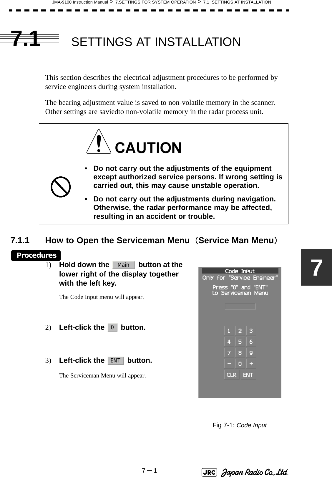
![JMA-9100 Instruction Manual > 6.TRUE AND FALSE ECHOES ON DISPLAY > 6.5 DISPLAY OF RADAR TRANSPONDER (SART)6-136[Example of Display] • When the SART function is set to ON, small targets around own ship will disappear from the radar display. So it is necessary to exercise full surveillance over the conditions around own ship by visual watch in order to avoid any collision or stranding.If two or more sets of radar equipment are installed on own ship, use one set of 9 GHz band radar for detection of the SART signal and operate others as normal radars for avoiding collision, monitoring targets around own ship, and checking on own ship’s position and avoidance of stranding.After end of detecting the START signal, turn the START display off. Then the radar returns normally to the nautical mode.Other ShipsLandSART codePosition of SARTAttention](https://usermanual.wiki/Japan-Radio/NKE1130.Users-Manual-2/User-Guide-994638-Page-65.png)

![7-2JMA-9100 Instruction Manual > 7.SETTINGS FOR SYSTEM OPERATION > 7.1 SETTINGS AT INSTALLATION7.1.2 GYRO I/F Settinga. Gyro Settings (STEP or SYNC)The GYRO I/F circuit of the system is designed to be compatible with most types of gyro compasses by simply setting the switches.Before power-on operation can be performed, the switches S1, S2, S5, S6, S7 and jumper TB105 on the gyro interface circuit (PC4201) must be set in accordance with the type of your gyro compass by performing the procedure below. The switches are factory-set for a gyration ratio of 180X and the step motor type. Make sure of the type of the gyro compass installed on the own ship before starting the procedure below.Procedures1) Set S5 to "OFF".The gyro compass and GYRO I/F are breaked off.2) Set S6 and S7 in accordance with the type of your gyro compass.There are two types of gyro compasses: one type outputs a step signal, and the other type outputs a synchro signal. Make sure of the type of the gyro compass installed on the own ship before setting the switches S6 and S7.3) Set the DIP switch S1 in accordance with the type of the compass.The items to be set are listed below. For the settings, refer to Table 7-1: Gyro and Log Select Switches (S1 DIP Switch).Step motor type: DC24V to DC100VSynchro-motor type: Primary excitation voltage 50 to 115 VACSynchro signal: Set the switches to [SYNC].Step signal: Set the switches to [STEP].S1-1: Type of gyro signal (step/synchro)S1-2/3: Gyration ratio of gyro compassS1-4: Gyration direction of gyro compassS1-5: Type of log signal (pulse/synchro)S1-7/8: Ratio of log signal](https://usermanual.wiki/Japan-Radio/NKE1130.Users-Manual-2/User-Guide-994638-Page-70.png)
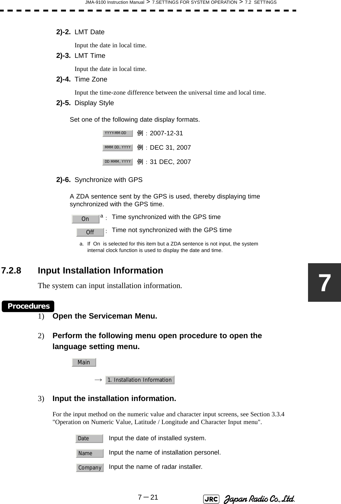
![JMA-9100 Instruction Manual > 7.SETTINGS FOR SYSTEM OPERATION > 7.2 SETTINGS7-1774) Set the starting azimuth of the sector blank by operating the [EBL] dial, and left-click the button. The start angle of the sector blank will be set.5) Set the ending azimuth of the sector blank by operating the [EBL] dial, and left-click the button.The end angle of the sector blank will be set.7.2.3 TNI Blank Setting (TNI Blank)Set a sector range and stop tuning operation in the bearing range.If a structure such as the mast is close to the radar antenna, automatic tuning operation may become unstable. In this case, set a TNI blank in the direction of the structure in order to stabilize the tuning operation.Only one type of a sector can be created. The TNI blank function operates in the relative bearing with the bow as the benchmark.7.2.3.1 TNI Blank Function On/Off (Sector)Procedures1) Open the Serviceman Menu.2) Perform the following menu open procedure to open the TNI Blank setting menu. → → 3) Select the item in the menu, and turn on or off the TNI blank function.7.2.3.2 TNI Blank Area Creation (Make Sector)Procedures1) Open the Serviceman Menu. : The TNI blank function is operated. : The TNI blank function is stopped.ENTENT2. Installation Menu9. Next2. TNI Blank1. TNI BlankOnOff](https://usermanual.wiki/Japan-Radio/NKE1130.Users-Manual-2/User-Guide-994638-Page-85.png)
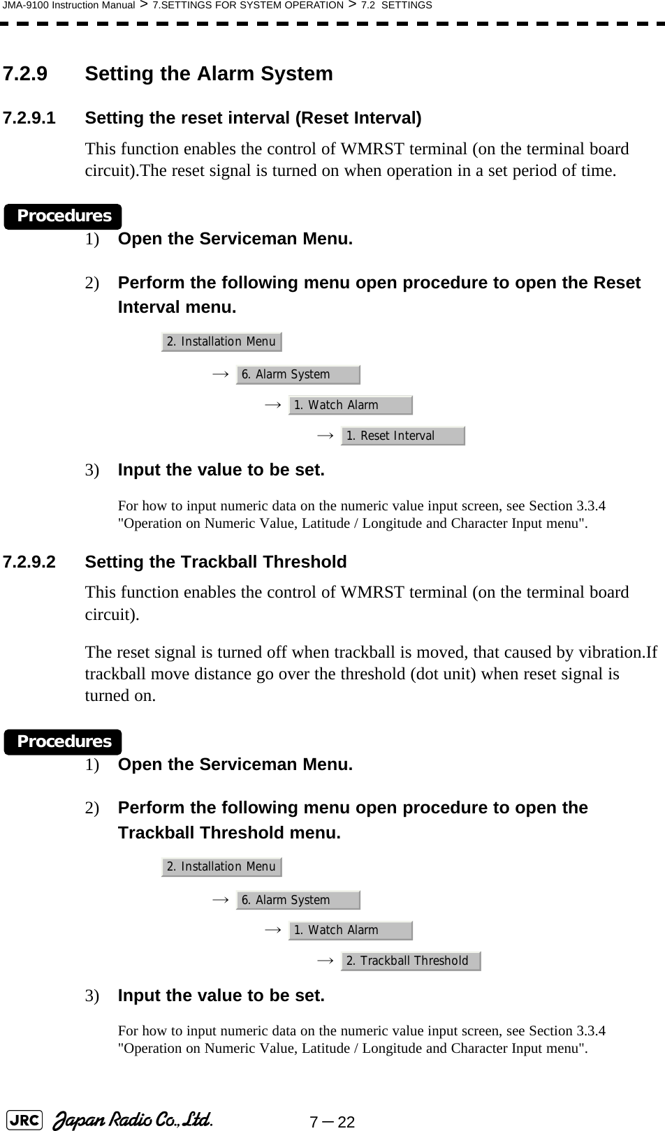
![7-18JMA-9100 Instruction Manual > 7.SETTINGS FOR SYSTEM OPERATION > 7.2 SETTINGS2) Perform the following menu open procedure to open the Sector Blank setting menu. → → 3) Left-click the button in the menu.The selected sector blank will be made.4) Set the starting azimuth of the TNI blank by operating the [EBL] dial, and left-click the button. The start angle of the TNI blank will be set.5) Set the ending azimuth of the TNI blank by operating the [EBL] dial, and left-click the button.The end angle of the TNI blank will be set.7.2.4 Setting of Bearing Pulses from Scanner Unit (Output Pulse)Set the output value of bearing pulses from the scanner unit. The system can set 2048 pulses or 4096 pulses. This setting is enabled only when the scanner unit of 25 or 30 kW is used.Procedures1) Open the Serviceman Menu.2) Perform the following menu open procedure to open the Output Pulse setting menu. → → 3) Set the number of pulses to be output by the scanner unit. aa. If a 10 kW antenna is used, 2048 is always set.:2048 pulses per antenna rotation (Recommended value):4096 pulses per antenna rotation2. Installation Menu9. Next2. TNI Blank2. Make SectorENTENT1. Adjust Menu4. TXRX Adjustment6. Output Pulse20484096](https://usermanual.wiki/Japan-Radio/NKE1130.Users-Manual-2/User-Guide-994638-Page-86.png)
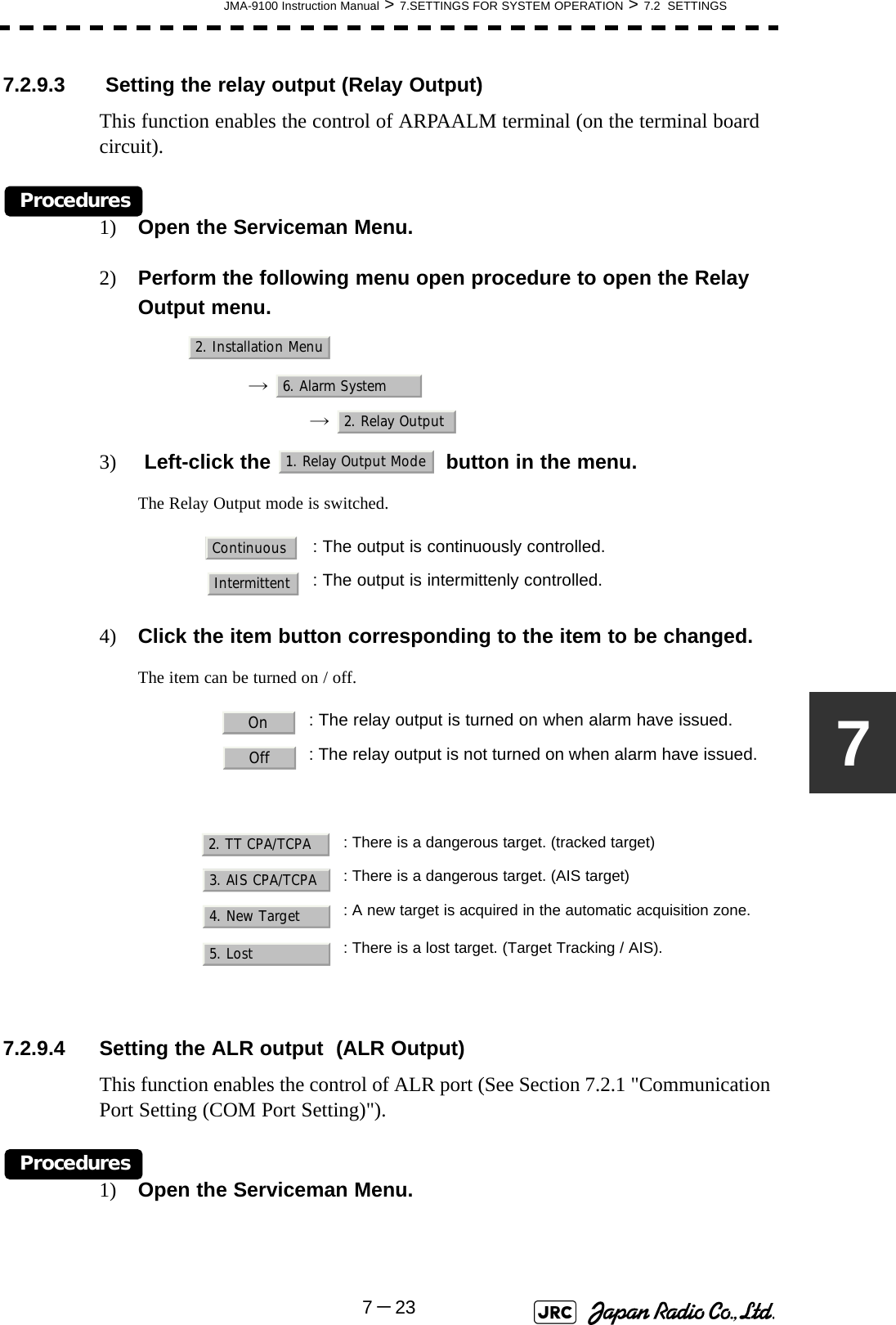
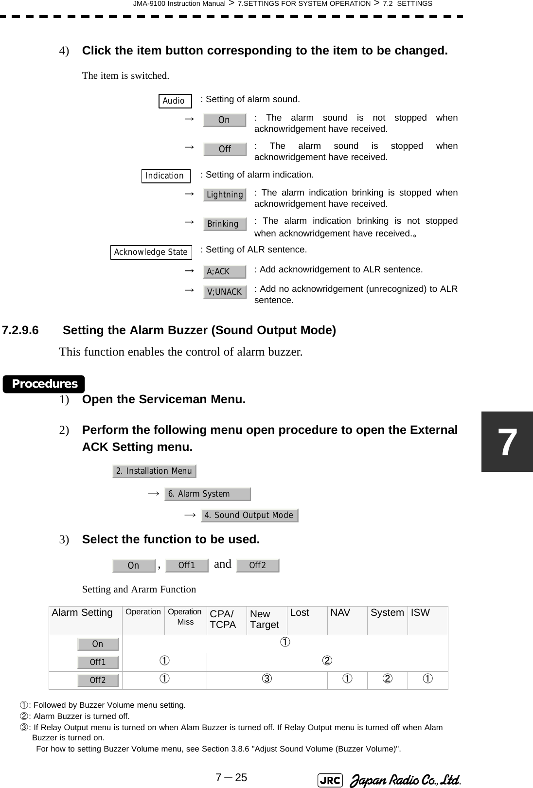
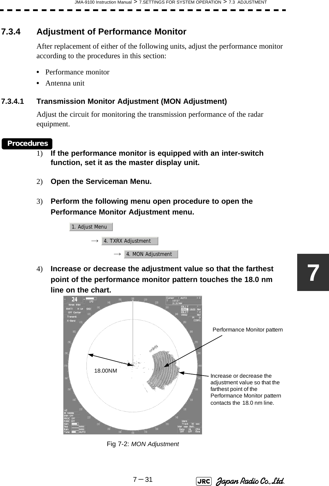
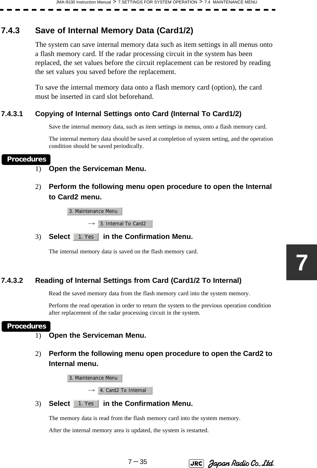
![JMA-9100 Instruction Manual > 7.SETTINGS FOR SYSTEM OPERATION > 7.3 ADJUSTMENT7-2977.3.3 Main Bang Suppression Level Adjustment (MBS)Main Bang Suppression is adjusted to suppress main bang, a reflection signal from 3D circuit including wave guide tube, that generally appears as a circular image focusing on the center of the radar display. Optimum adjustment allows main bang image to remain lightly on the display.7.3.3.1 Adjustment of Main Bang Suppression Level (MBS Level)Procedures1) Open the Serviceman Menu.2) Perform the following menu open procedure to open the MBS level adjustment menu.→ → 3) Set the radar as follows:•Set the radar range to 0.125 NM.•Set the radar video enhance function (ENH) to OFF.•Set the image processing (PROC) to OFF.•Turn the [RAIN] control to the minimum position (fully to the left).•Turn the [GAIN] control to the maximum position (fully to the right).•Turn the [SEA] control to achieve the strength with which main bang can be judged.4) Adjust the value so that the main bang can be erased. Do not change this adjusted level carelessly.Incorrect adjustment may erase targets in point-blank range and cause collision, resulting in death or serious injury.9. RADAR/TT Initial Setup3. MBS1. MBS Level](https://usermanual.wiki/Japan-Radio/NKE1130.Users-Manual-2/User-Guide-994638-Page-97.png)
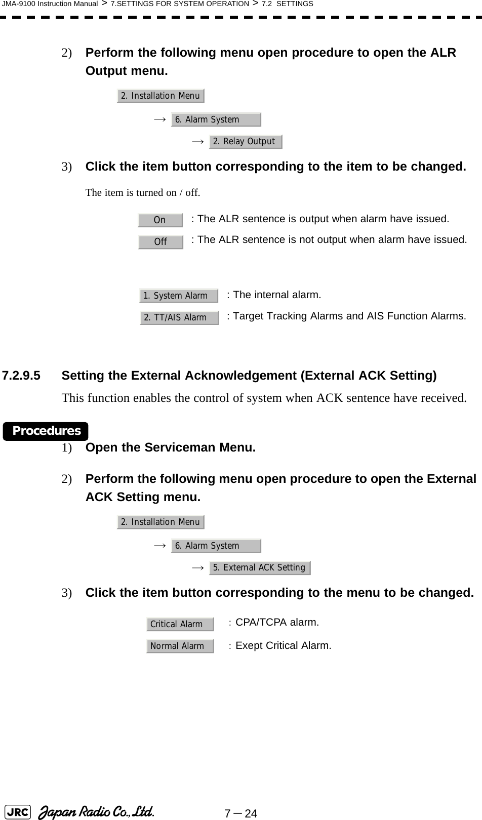
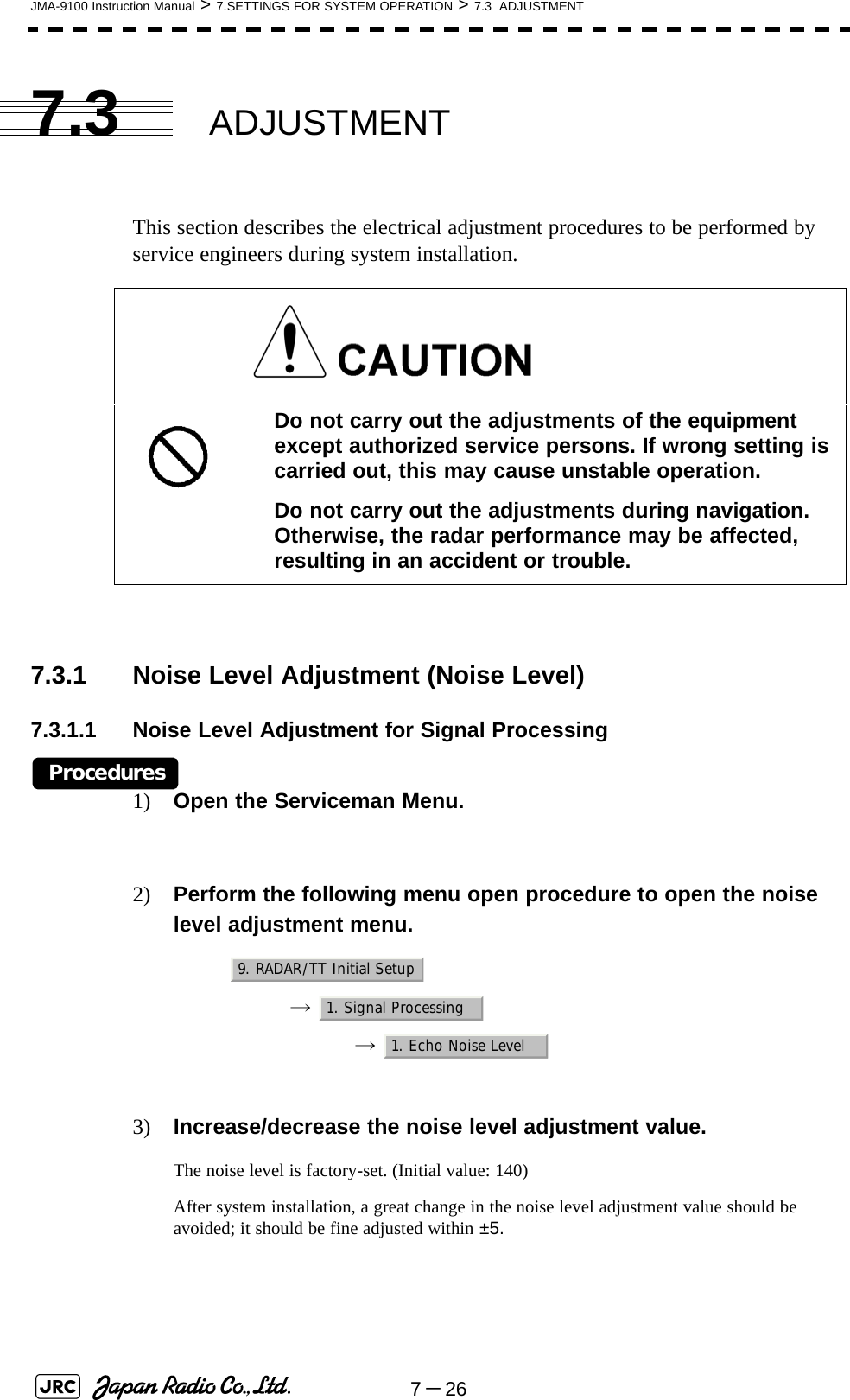
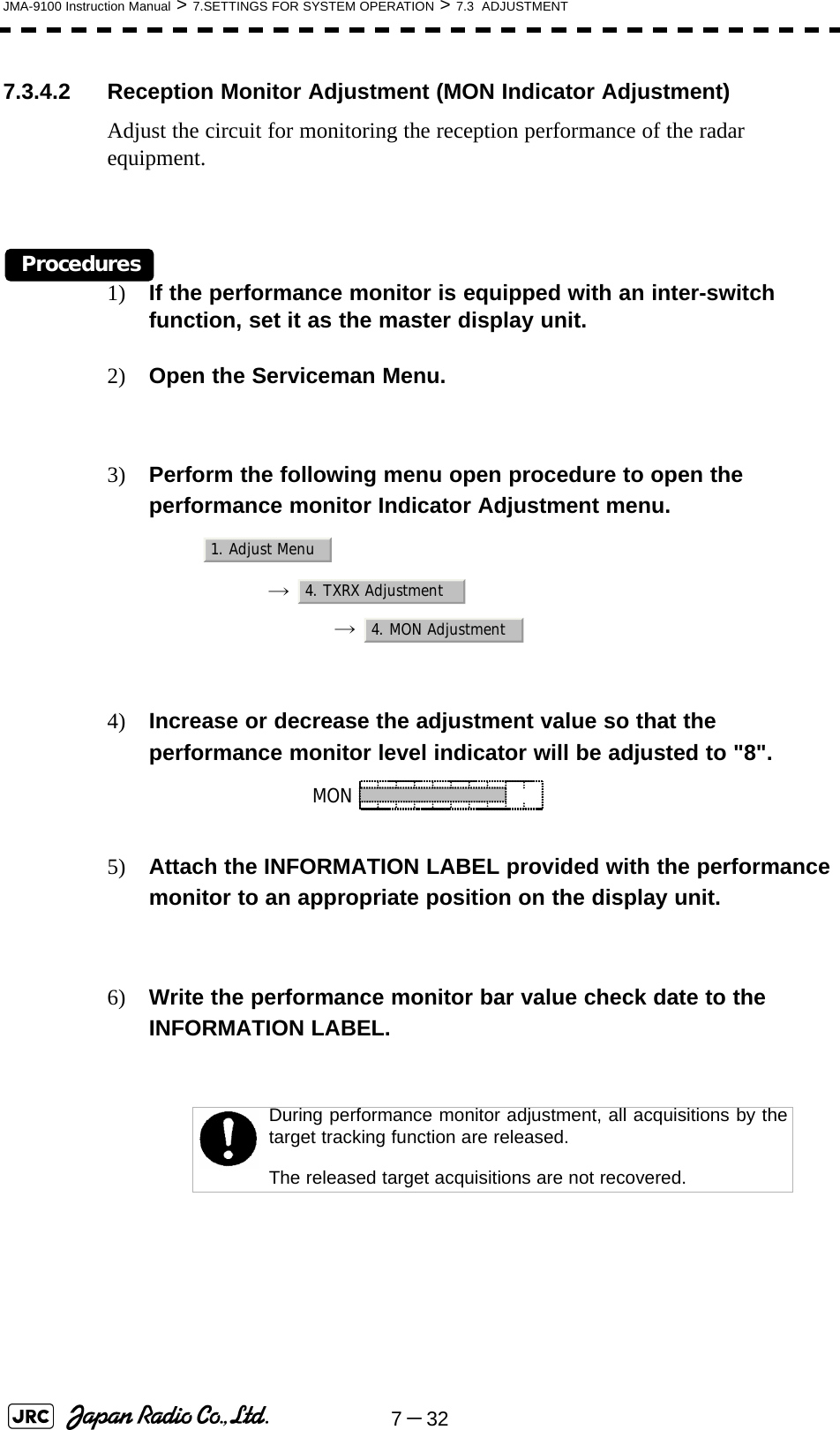
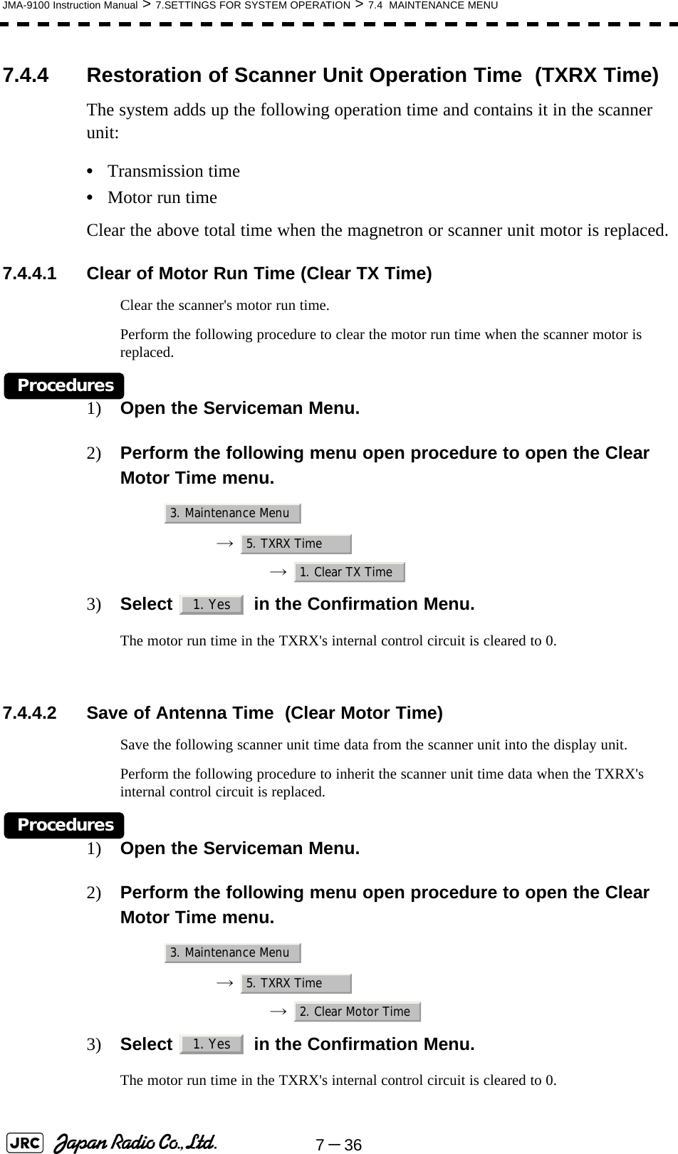
![7-30JMA-9100 Instruction Manual > 7.SETTINGS FOR SYSTEM OPERATION > 7.3 ADJUSTMENT7.3.3.2 Adjustment of Main Bang Suppression Area (MBS Area)Procedures1) Open the Serviceman Menu.2) Perform the following menu open procedure to open the MBS Area adjustment menu.→ → 3) Set the radar as follows:•Set the radar range to 0.125 NM.•Set the radar video enhance function (ENH) to OFF.•Set the image processing (PROC) to OFF.•Turn the [RAIN] control to the minimum position (fully to the left).•Turn the [GAIN] control to the maximum position (fully to the right).•Turn the [SEA] control to achieve the strength with which main bang can be judged.4) Adjust the value so that the main bang can be erased.9. RADAR/TT Initial Setup3. MBS2. MBS Area](https://usermanual.wiki/Japan-Radio/NKE1130.Users-Manual-2/User-Guide-994638-Page-98.png)
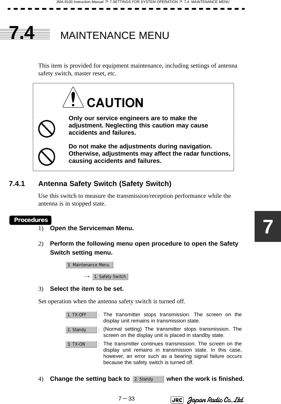
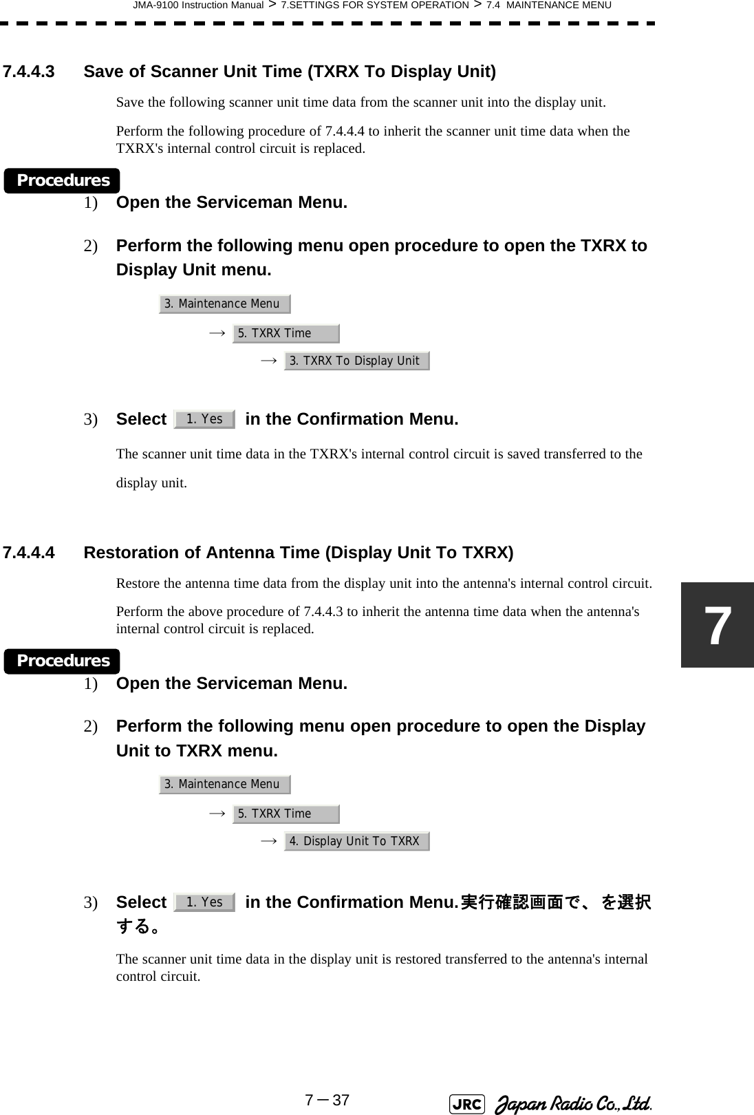
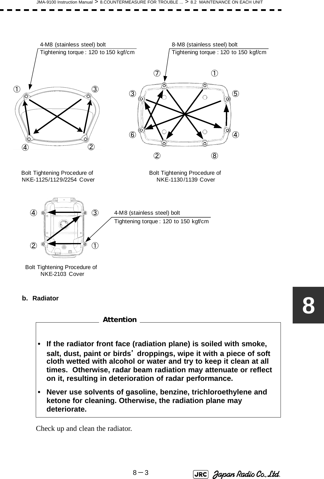
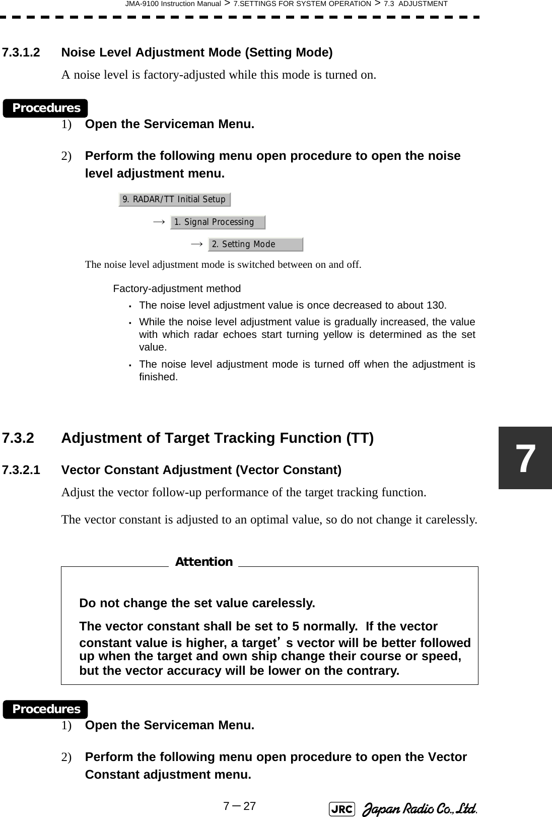
![8-6JMA-9100 Instruction Manual > 8.COUNTERMEASURE FOR TROUBLE ... > 8.3 PERFORMANCE CHECK8.3 PERFORMANCE CHECKMake operational check on the radar equipment regularly and if any problem is found, investigate it immediately. Pay special attention to the high voltage sections in checking and take full care that no trouble is caused by any error or carelessness in measurement. Take note of the results of checking, which can be used effectively in the next check work.Operational check shall be made in accordance with Table 8-1 Function Check List in the order as specified in it.8.3.1 Check Performance on Test MenuThe radar operating state can be checked by opening the Test Menu.Table8-1: Performance Check ListEquipment Item to be checked Criteria RemarksTransmitter Receiver Unit Tuning LED of Receiver The LED is lighting during operation 48NM rangeDisplay Unit Video and echoes on the screen SensitivityLCD brilliance can be controlled correctlyVarious markersVarious numerical indicationsLightingCan be correctly controlledMemory See the Section [1] "Memory Test"Communications Lines See the Section [3] "Check ofCommunication Lines (Line Test)"Power Supply, Backup Battery See the Section [4] "Supply Voltage" Monitor See the Section 8.3.1.2 "Monitor Test"Operation Unit See the Section 8.3.1.3 "Operation UnitTest (Keyboard Test)" System Alarm Log Display See the Section 8.3.1.5 "System AlarmLog display" System Information Display See the Section 8.3.1.6 "SystemInformation" Magnetron current See the Section 8.3.1.7 "MagnetronCurrent" Target Tracking See the Section 5.2.7 "Operation Test(TT Test Menu)" Scanner Unit Signals from the Scanner Unit See the Section [2] "TXRX Test"Performance Monitor See the Section 8.3.1.4 "Check of thePerformance Monitor (MON Display)"](https://usermanual.wiki/Japan-Radio/NKE1130.Users-Manual-2/User-Guide-994638-Page-114.png)
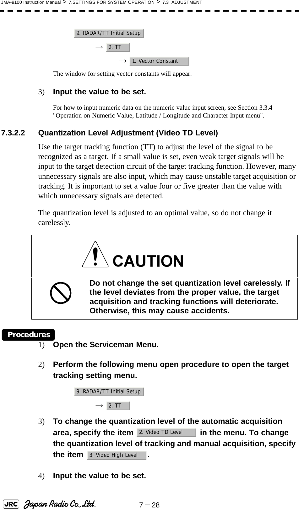
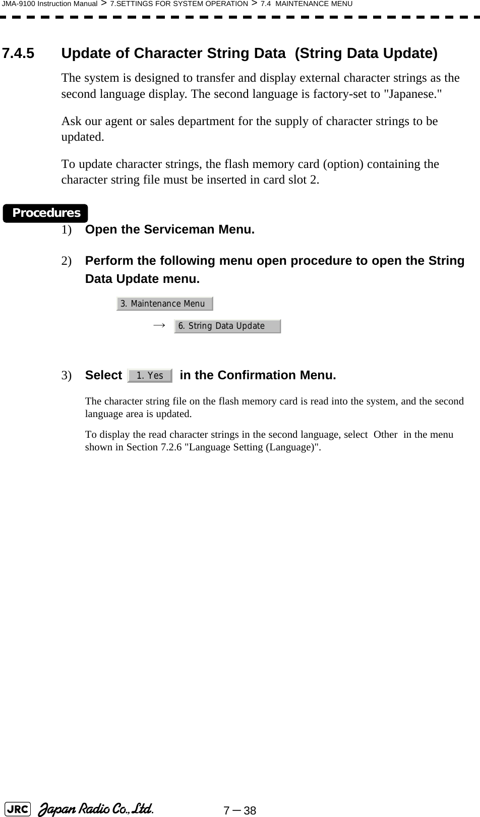
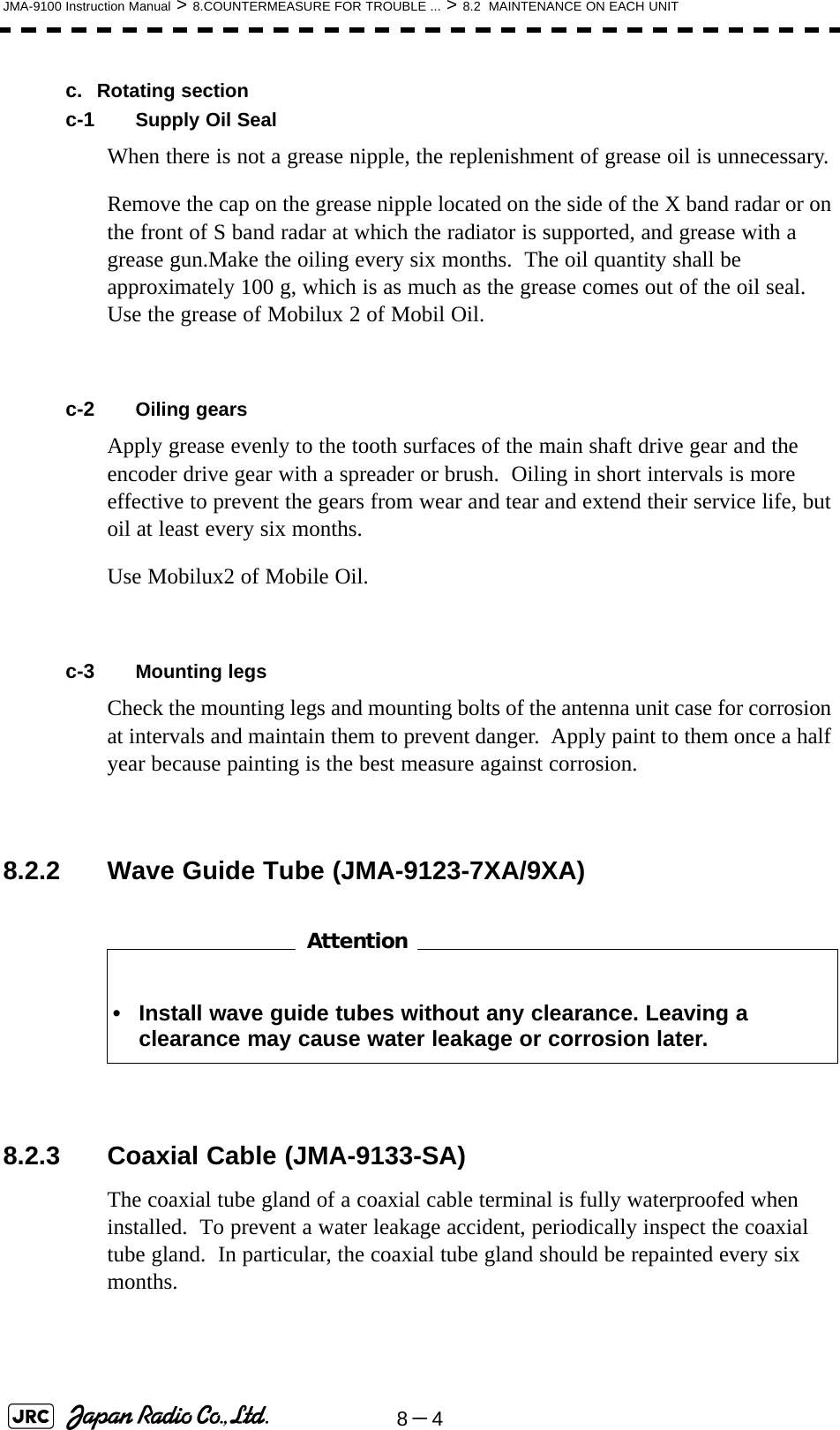
![JMA-9100 Instruction Manual > 8.COUNTERMEASURE FOR TROUBLE ... > 8.3 PERFORMANCE CHECK8-78Procedures1) Perform the following menu open procedure to open the Test Menu.→ 2) Select the items to be checked.The list of check items will appear.8.3.1.1 Self-diagnosis function (Self Test)Check of memory, scanner unit, and communications Lines[1] Memory TestChecks for the performance of built-in memory.When no abnormality is found, OK is displayed. When an abnormality is found, NG is displayed. 8.3.1.1Self-diagnosis function (Self Test)8.3.1.2Monitor Test8.3.1.3Operation Unit Test (Keyboard Test)8.3.1.4Check of the Performance Monitor (MON Display)8.3.1.5System Alarm Log display8.3.1.6System Information8.3.1.7Magnetron Current[1]Memory Test[2]TXRX Test[3]Check of Communication Lines (Line Test)[4]Supply VoltageSDRAM CheckSRAM CheckFLASH ROM CheckGRAPHIC CheckMain9. Test Menu1. Self Test2. Monitor Test3. Keyboard Test4. MON Display5. System Alarm Log6. System InformationMagnetron Current1. Memory Test2. TXRX Test3. Line Test4. Supply Voltage1. SDRAM2. SRAM3. FLASH ROM4. GRAPHIC](https://usermanual.wiki/Japan-Radio/NKE1130.Users-Manual-2/User-Guide-994638-Page-115.png)
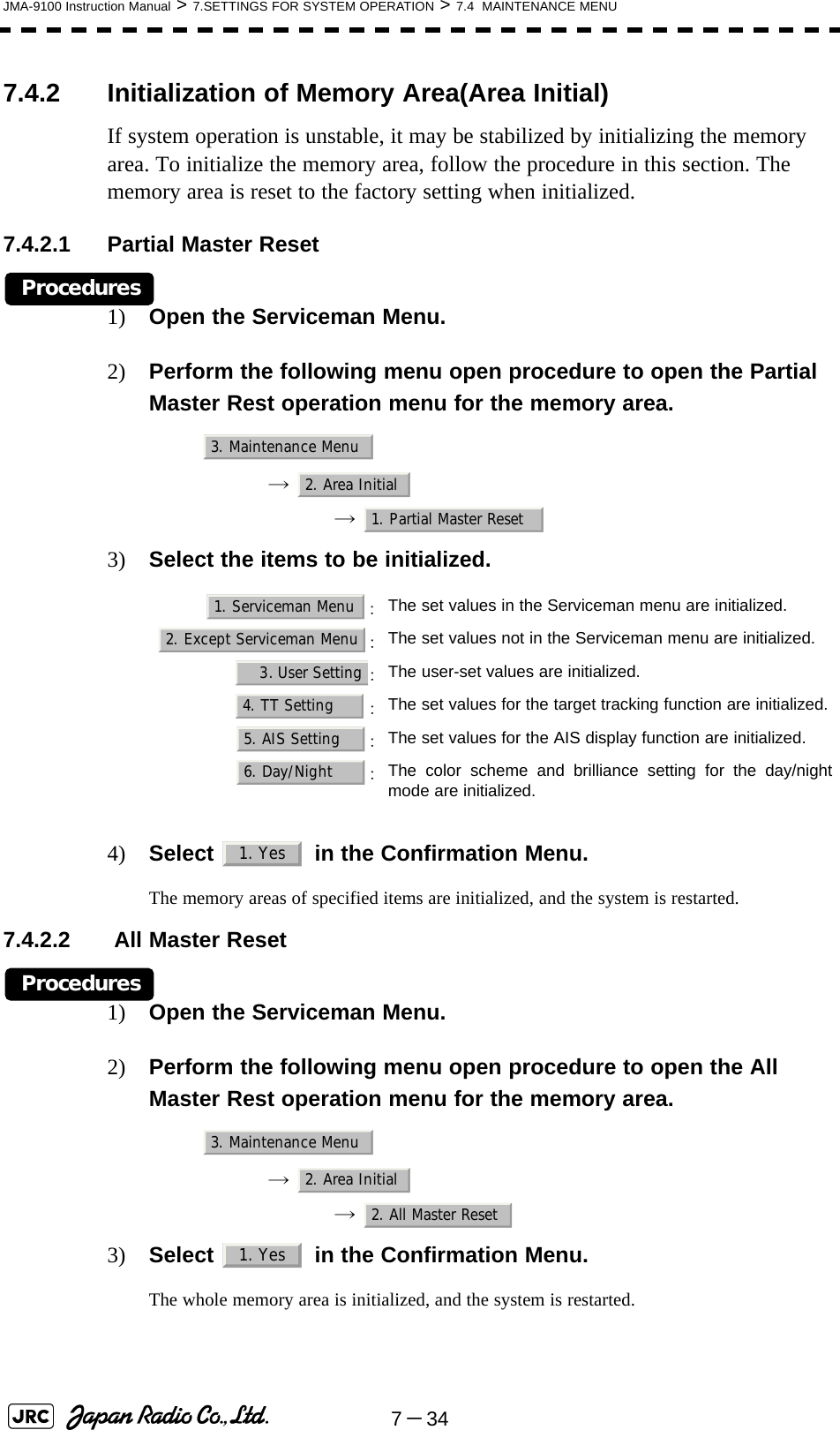
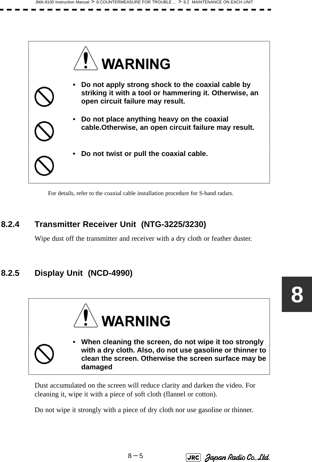
![8-8JMA-9100 Instruction Manual > 8.COUNTERMEASURE FOR TROUBLE ... > 8.3 PERFORMANCE CHECK[2] TXRX TestChecks for signals from the scanner.When no abnormality is found, OK is displayed. When an abnormality is found, NG is displayed.In standby, ** will appear.[3] Check of Communication Lines (Line Test)Check the status of communications with options.When no abnormality is found, OK is displayed. When an abnormality is found, NG is displayed.The status display field of equipment not connected is left blank.[4] Supply VoltageCheck the voltage of internal power supply. Scanner's safety switch checkScanner rotation signal checkHeading line signal checkCheck on the load current of high voltage inthe modulatorRadar trigger signal checkRadar video checkCheck on connection with the transmitter-receiverCheck on connection with the signal processing circuitCheck on connection with the target tracking unitCheck on connection with the GYRO I/F unitCheck on connection with the interswitchItem Normal value12V 11.4 to 12.6V5V 4.75 to 5.25V3.3V 3.14 to 3.46VBattery 2.5V or moreSafety SwitchAZI PulseHL PulseMH CurrentTriggerVideoTXRXSIG. PROCTT GYRO I/F ISW](https://usermanual.wiki/Japan-Radio/NKE1130.Users-Manual-2/User-Guide-994638-Page-116.png)
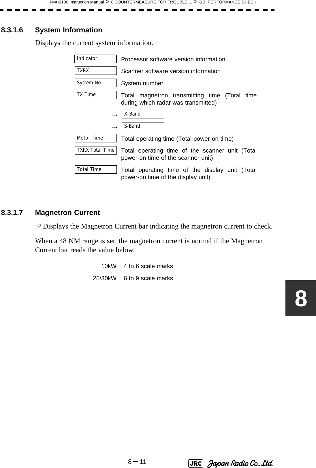
![JMA-9100 Instruction Manual > 8.COUNTERMEASURE FOR TROUBLE ... > 8.3 PERFORMANCE CHECK8-988.3.1.2 Monitor TestChecks for the display.The test pattern will be shown on the display.To return to the normal display, press any key.If errors occur in the monitor, no test pattern will appear.8.3.1.3 Operation Unit Test (Keyboard Test)Checks for the controls and switches of the operation panel.[1] Key TestChecks for the controls and switches of the operation panel.Each key on the operation panel on the display is shown in reverse video at the same time the key is pressed, and the name of the pressed key is displayed.[2] Buzzer TestChecks for the operation panel buzzer.The buzzer will sound. The buzzer automatically stops after it sounds for a specified length of time.[3] Light TestChecks for the control panel light.The brightness of the operation panel is gradually intensified at four levels. :All colors are filled with white.:A white box is displayed on the black background of 1280×1024dot.:Displays rectangle X 2, circle X 2, and cross-shape X13(white lines on the black background).:Displays “H” of 9 dots X 9 dots on the entire screen (whitecharacter on the black background).:Gray scale display (16 levels):Displays a color bar.:Displays the VDR test pattern.:Displays the specified color.[1]Key Test[2]Buzzer Test[3]Light Test1. Pattern12. Pattern23. Pattern34. Pattern45. Pattern56. Pattern67. Pattern78. Pattern81. Key Test2. Buzzer Test3. Light Test](https://usermanual.wiki/Japan-Radio/NKE1130.Users-Manual-2/User-Guide-994638-Page-117.png)
![8-10JMA-9100 Instruction Manual > 8.COUNTERMEASURE FOR TROUBLE ... > 8.3 PERFORMANCE CHECK8.3.1.4 Check of the Performance Monitor (MON Display)Displays the performance monitor status.Procedures1) Turn the [VRM] dial to make adjustments so that the farthest point of the performance monitor pattern.The of is displayed.8.3.1.5 System Alarm Log displayDisplays previously occurred system errors with the dates and times when they occurred.The current error is displayed at the lower right of the radar display. For details, refer to Section 9.1.1 "List of Alarms and other Indications".The Error log display button (page2-31 Alarm) is clicked, in the same way as that one.To erase the alarm logs, press the button in the log display window.Transmitter system attenuation value check.→ Receiver system attenuation value check.→ → *Transmitter SystemAttenuation Value*Receiver SystemMON Pattern RangeAttenuation ValueAttenuation Value *Receiver SystemAll Clear](https://usermanual.wiki/Japan-Radio/NKE1130.Users-Manual-2/User-Guide-994638-Page-118.png)
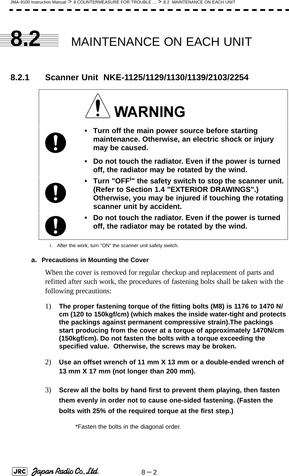
![8-14JMA-9100 Instruction Manual > 8.COUNTERMEASURE FOR TROUBLE ... > 8.4 REPLACEMENT OF MAJOR PARTS8.4.2.1 Scanner Unit NKE-1130[Required tools]•A Phillips screwdriver for 4 mm screw•A Phillips screwdriver for 6 mm screw•A wrench (width across flats 13 mm, for M8 screws) [Replacement procedure]1) Before starting part replacement work, turn off the safety switch of the scanner unit.The safety switch is located on the rear (stern) side. Remove the cover and turn off (to the lower side) the safety switch. 2) Remove the pedestal cover.Make sure that there is no foreign matter or dust adhered to the gasket when you put the cover on.Bow sideTurn off the safety switch.Remove the eight hexagonal screws.Removing the port side cover](https://usermanual.wiki/Japan-Radio/NKE1130.Users-Manual-2/User-Guide-994638-Page-122.png)
![JMA-9100 Instruction Manual > 8.COUNTERMEASURE FOR TROUBLE ... > 8.4 REPLACEMENT OF MAJOR PARTS8-1583) Remove the cover on the left (port) side and check that there is no remaining electric charge in the modulation high-voltage circuit board.Remove the two screws (M4) holding the magnetron cables (both yellow and green).4) Remove the eight screws (M6) to remove the fixture holding the magnetron. The screws cannot be removed from the fixture, so loosen the all eight screws and remove the magnetron together with the fixture.The magnetron is held by a hook, but be careful not to let it fall.Use a non-magnetic screwdriver. If the magnetron comes into contact with any metal (tool), its performance may deteriorate.5) Install the new magnetron together with the fixture and tighten the screws to hold the cables.Follow the removal procedure in the reverse order.Do not forget to tighten the screws and connect the cables. [Operation check]After you have completed the replacement work, follow the procedure below to check the operation.MagnetronRemove the yellow cable.Remove the green cable.Remove the two screws.Remove the magnetron.Remove the metal fixture.Loosen the eight screws.](https://usermanual.wiki/Japan-Radio/NKE1130.Users-Manual-2/User-Guide-994638-Page-123.png)
![8-16JMA-9100 Instruction Manual > 8.COUNTERMEASURE FOR TROUBLE ... > 8.4 REPLACEMENT OF MAJOR PARTS1) Turn on the power supply for the radar. Allow sufficient time for the radar to be preheated (about 20 to 30 minutes / bring the radar unit to STBY mode).2) Start emitting radio waves from the short pulse range and gradually change the emissions to the long pulse range. Open the service engineer menu to perform tuning adjustment. If operation becomes unstable, bring the radar unit back to STBY mode and restart emission after allowing for an interval of 5 to 10 minutes.3) Emit radio waves in long pulse range mode for about 15 minutes and reopen the service engineer menu to perform tuning adjustment. Adjust the setting in the service engineer menu until the tuning indication bar on the display unit reaches the 8th calibration marking. Check in the service engineer menu that the magnetron current is between the 6th and 9th calibration markings. 4) Finally, initialize the transmission time in the service engineer menu. 8.4.2.2 Scanner Unit NKE-2254, NKE-1125[Required tools]•A Phillips screwdriver for 4 mm screw•A Phillips screwdriver for 6 mm screw•A wrench (width across flats 13 mm, for M8 screws) [Replacement procedure]1) Before starting part replacement work, turn off the safety switch of the scanner unit.Bow directionTurn off the safety switch.](https://usermanual.wiki/Japan-Radio/NKE1130.Users-Manual-2/User-Guide-994638-Page-124.png)
![8-18JMA-9100 Instruction Manual > 8.COUNTERMEASURE FOR TROUBLE ... > 8.4 REPLACEMENT OF MAJOR PARTSUse a non-magnetic screwdriver. If the magnetron comes into contact with any metal (tool), its performance may deteriorate.6) After having replaced the magnetron, reassemble the unit by following the disassembly procedure in the reverse order.Do not forget to tighten the bolts and screws, and do not forget to reconnect the cables.Extreme care should be taken to connect the leads (yellow and green) to the magnetron for prevention of contact with other parts or the casing. Contact may cause them to discharge.[Operation check]After you have completed the replacement work, follow the procedure below to check the operation.1) Turn on the power supply for the radar. Allow sufficient time for the radar to be preheated (about 20 to 30 minutes / bring the radar unit to STBY mode).2) Start emitting radio waves from the short pulse range and gradually change the emissions to the long pulse range. Open the service engineer menu to perform tuning adjustment. If operation becomes unstable, bring the radar unit back to STBY mode and restart emission after allowing for an interval of 5 to 10 minutes.3) Emit radio waves in long pulse range mode for about 15 minutes and reopen the service engineer menu to perform tuning adjustment. Adjust the setting in the service engineer menu until the tuning indication bar on the display unit reaches the 8th calibration marking. Check in the service engineer menu that the magnetron current is between the 6th and 9th calibration markings. 4) Finally, initialize the transmission time in the service engineer menu.](https://usermanual.wiki/Japan-Radio/NKE1130.Users-Manual-2/User-Guide-994638-Page-126.png)
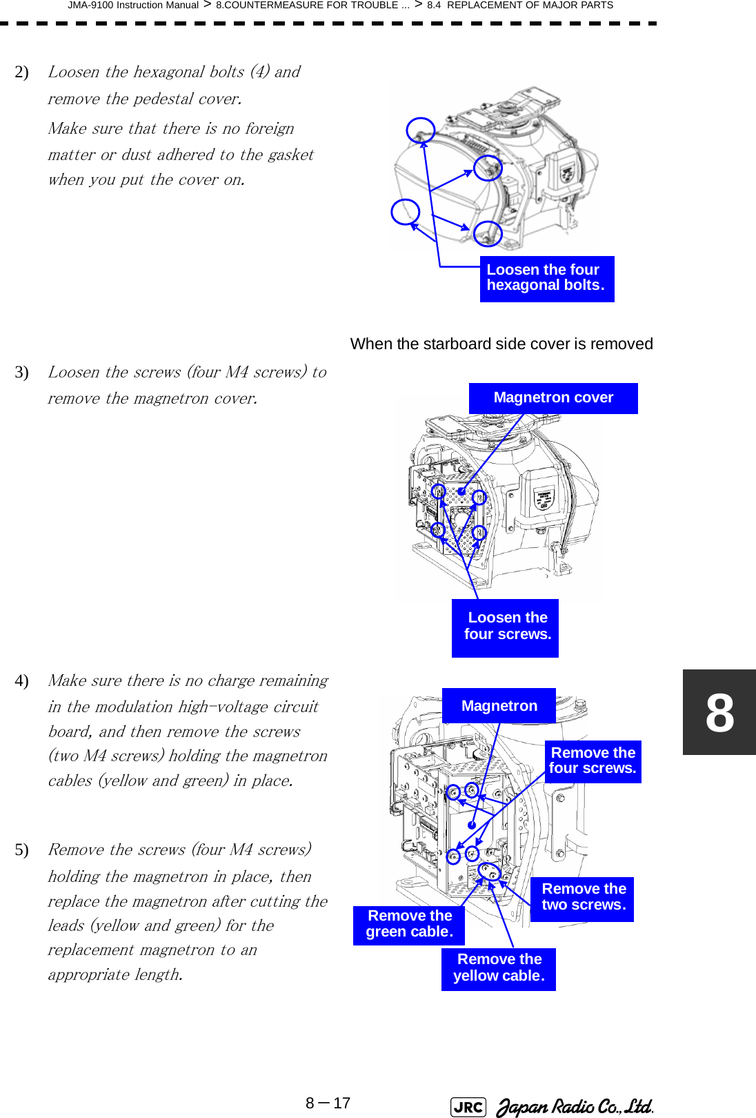
![JMA-9100 Instruction Manual > 8.COUNTERMEASURE FOR TROUBLE ... > 8.4 REPLACEMENT OF MAJOR PARTS8-1988.4.2.3 Scanner Unit NKE-2103[Required tools]•A Phillips screwdriver for 4 mm screw•A Phillips screwdriver for 6 mm screw•A wrench (width across flats 13 mm, for M8 screws) 1) Before starting part replacement work, turn off the safety switch on the bottom of the scanner unit.2) Loosen the hexagonal bolts (four bolts) and open the upper cover until the stopper of the stay operates.When closing the upper cover, release the stay stopper and then tighten the cover.Bow directionTurn off the safety switch.Loosen the four hexagonal bolts.Stay](https://usermanual.wiki/Japan-Radio/NKE1130.Users-Manual-2/User-Guide-994638-Page-127.png)
![JMA-9100 Instruction Manual > 8.COUNTERMEASURE FOR TROUBLE ... > 8.4 REPLACEMENT OF MAJOR PARTS8-218Do not forget to tighten the bolts and screws, and do not forget to reconnect the cables.Extreme care should be taken to connect the leads (yellow and green) to the magnetron for prevention of contact with other parts or the casing.[Operation check]After you have completed the replacement work, follow the procedure below to check the operation.1) Turn on the power supply for the radar. Allow sufficient time for the radar to be preheated (about 20 to 30 minutes / bring the radar unit to STBY mode).2) Start emitting radio waves from the short pulse range and gradually change the emissions to the long pulse range. Open the service engineer menu to perform tuning adjustment. If operation becomes unstable, bring the radar unit back to STBY mode and restart emission after allowing for an interval of 5 to 10 minutes.3) Emit radio waves in long pulse range mode for about 15 minutes and reopen the service engineer menu to perform tuning adjustment. Adjust the setting in the service engineer menu until the tuning indication bar on the display unit reaches the 8th calibration marking. Check in the service engineer menu that the magnetron current is between the 4th and 6th calibration markings. 4) Finally, initialize the transmission time in the service engineer menu. 8.4.2.4 Transmitter Receiver Unit NTG-3230[Required tools]A flatblade screwdriver for 6 mm screws•A Phillips screwdriver for 4 mm screw•A Phillips screwdriver for 6 mm screw](https://usermanual.wiki/Japan-Radio/NKE1130.Users-Manual-2/User-Guide-994638-Page-129.png)
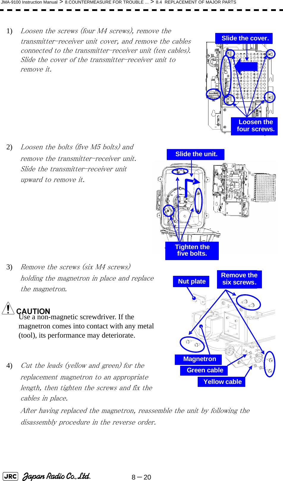
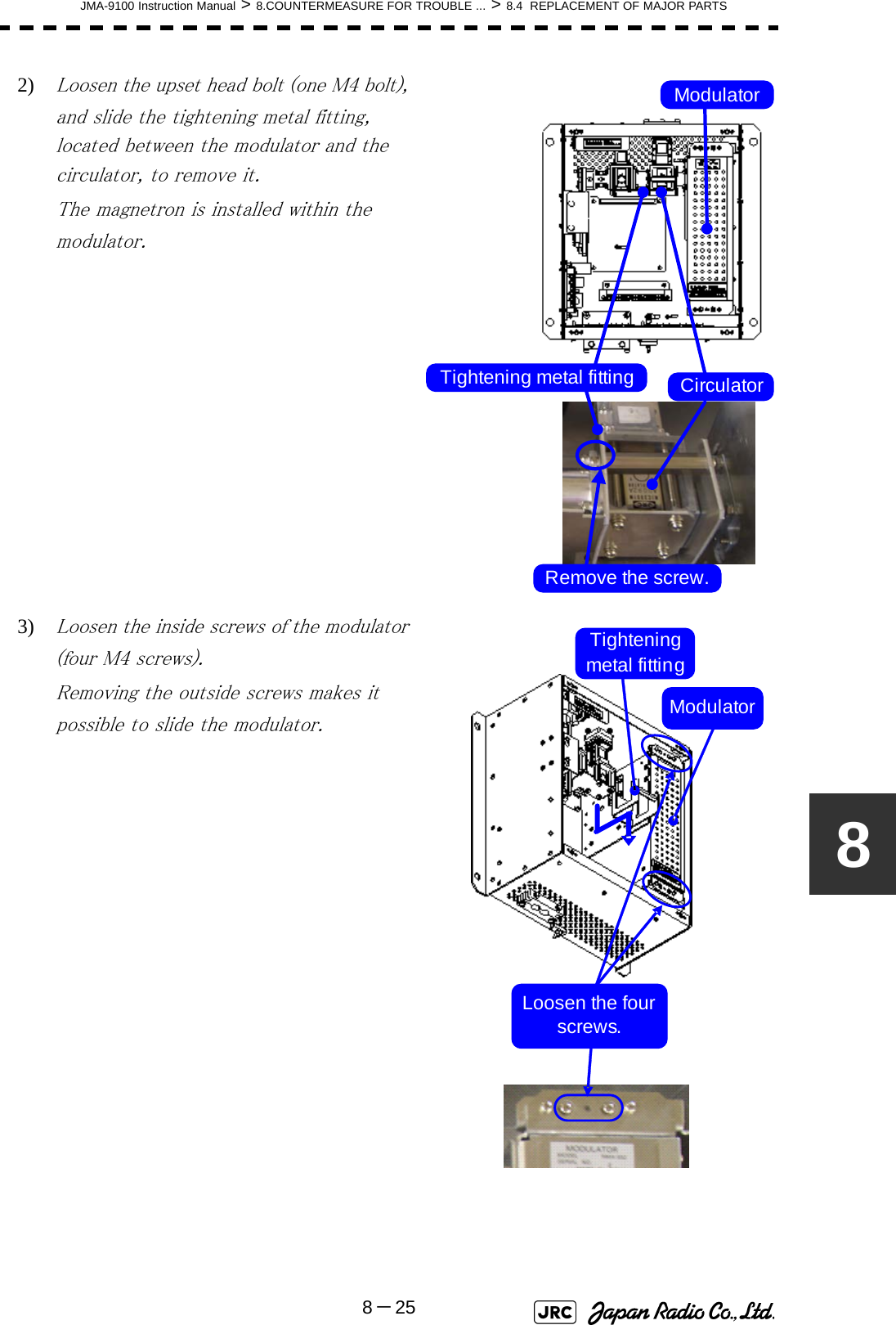
![8-22JMA-9100 Instruction Manual > 8.COUNTERMEASURE FOR TROUBLE ... > 8.4 REPLACEMENT OF MAJOR PARTS[Replacement procedure]1) Loosen the four screws and remove the cover.The screws are slotted captive screws.Use a flatblade screwdriver.2) Remove the screws (six M4 screws) and slide the modulator cover to the right to remove it.Remove the four screws.Loosen the six screws.Modulator cover](https://usermanual.wiki/Japan-Radio/NKE1130.Users-Manual-2/User-Guide-994638-Page-130.png)
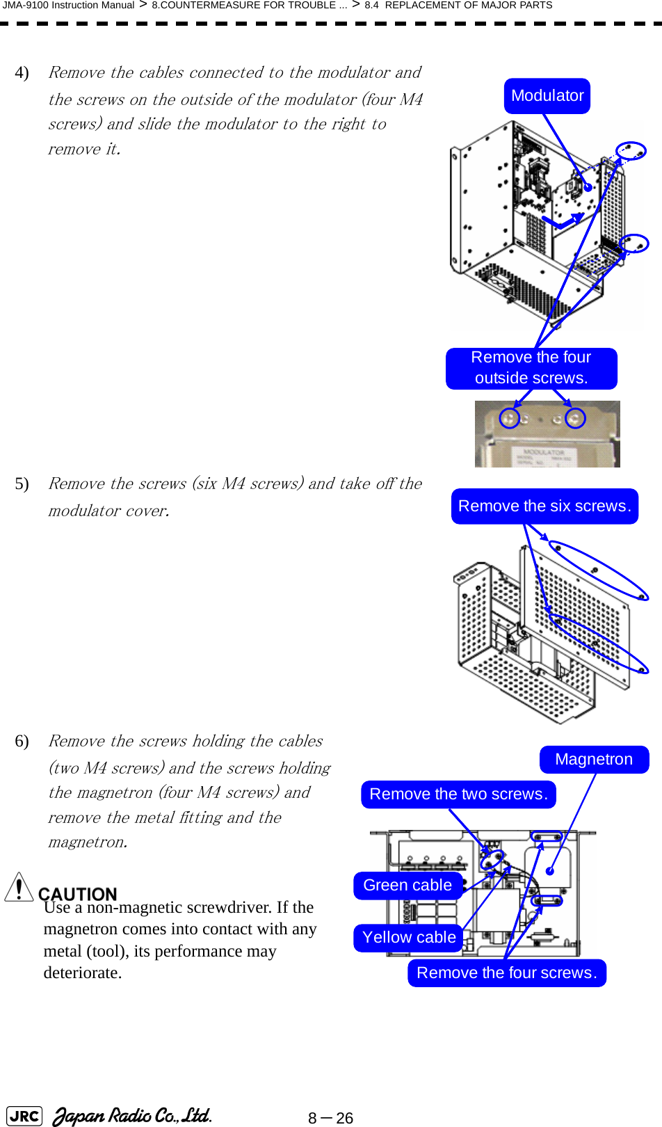
![JMA-9100 Instruction Manual > 8.COUNTERMEASURE FOR TROUBLE ... > 8.4 REPLACEMENT OF MAJOR PARTS8-2383) Remove the screws holding the cables (two M4 screws) and the bolts holding the magnetron (eight M6 screws) and remove the metal fitting and the magnetron.Use a non-magnetic screwdriver. If the magnetron comes into contact with any metal (tool), its performance may deteriorate.4) Be careful to attach the colored cables (yellow and green) to the correct connections on the replacement magnetron.After having replaced the magnetron, reassemble the unit by following the disassembly procedure in the reverse order.Do not forget to tighten the bolts and screws, and do not forget to reconnect the cables.[Operation check]After you have completed the replacement work, follow the procedure below to check the operation.1) Turn on the power supply for the radar. Allow sufficient time for the radar to be preheated (about 20 to 30 minutes / bring the radar unit to STBY mode).2) Start emitting radio waves from the short pulse range and gradually change the emissions to the long pulse range. Open the service engineer menu to perform tuning adjustment. If operation becomes unstable, bring the radar unit back to STBY mode and restart emission after allowing for an interval of 5 to 10 minutes.3) Emit radio waves in long pulse range mode for about 15 minutes and reopen the service engineer menu to perform tuning adjustment. Yellow cableMagnetronModulatorGreencableRemove the eight bolts.Remove the two screws.Green cableYellow cable](https://usermanual.wiki/Japan-Radio/NKE1130.Users-Manual-2/User-Guide-994638-Page-131.png)
![8-24JMA-9100 Instruction Manual > 8.COUNTERMEASURE FOR TROUBLE ... > 8.4 REPLACEMENT OF MAJOR PARTSAdjust the setting in the service engineer menu until the tuning indication bar on the display unit reaches the 8th calibration marking. Check in the service engineer menu that the magnetron current is between the 6th and 9th calibration markings. 4) Finally, initialize the transmission time in the service engineer menu. 8.4.2.5 Transmitter Receiver Unit NTG-3225[Required tools]A flatblade screwdriver for 6 mm screws・A Phillips screwdriver for 4 mm screw[Replacement procedure]1) Loosen the four screws and remove the cover.The screws are slotted captive screws.Use a flatblade screwdriver.Loosen the four screws.](https://usermanual.wiki/Japan-Radio/NKE1130.Users-Manual-2/User-Guide-994638-Page-132.png)
![JMA-9100 Instruction Manual > 8.COUNTERMEASURE FOR TROUBLE ... > 8.4 REPLACEMENT OF MAJOR PARTS8-2787) Be careful to attach the colored cables (yellow and green) to the correct connections on the replacement magnetron.After having replaced the magnetron, reassemble the unit by following the disassembly procedure in the reverse order.Do not forget to tighten the bolts and screws, and do not forget to reconnect the cables.[Operation check]After you have completed the replacement work, follow the procedure below to check the operation.1) Turn on the power supply for the radar. Allow sufficient time for the radar to be preheated (about 20 to 30 minutes / bring the radar unit to STBY mode).2) Start emitting radio waves from the short pulse range and gradually change the emissions to the long pulse range. Open the service engineer menu to perform tuning adjustment. If operation becomes unstable, bring the radar unit back to STBY mode and restart emission after allowing for an interval of 5 to 10 minutes.3) Emit radio waves in long pulse range mode for about 15 minutes and reopen the service engineer menu to perform tuning adjustment. Adjust the setting in the service engineer menu until the tuning indication bar on the display unit reaches the 8th calibration marking. Check in the service engineer menu that the magnetron current is between the 6th and 9th calibration markings. 4) Finally, initialize the transmission time in the service engineer menu. MagnetronPulse transformerYellow cableGreen cable](https://usermanual.wiki/Japan-Radio/NKE1130.Users-Manual-2/User-Guide-994638-Page-135.png)
![8-28JMA-9100 Instruction Manual > 8.COUNTERMEASURE FOR TROUBLE ... > 8.4 REPLACEMENT OF MAJOR PARTS8.4.3 Replacement of Motor8.4.3.1 Scanner Unit NKE-1139/1130[Required tools]•A wrench (width across flats 17 mm, for M10 screws)•A Phillips screwdriver for 4 mm screw•Tools for removing the cover from the scanner unit.(Refer to the 8.4.2.1)[Replacement procedure]1) Remove the cover on the right (starboard) side (see 8.4.2.1) and loosen the four screws (M4) to remove the driver unit, which has the motor driver circuit board on its back side. Disconnect the cables connecting the motor to the motor driver circuit board.Replacement of motor must be made by specialized servicepersonnel. For details, refer to Service Manual.Driver unit (driver circuit board at the back side)Remove the four screws.Driver circuit board Disconnect the cables.](https://usermanual.wiki/Japan-Radio/NKE1130.Users-Manual-2/User-Guide-994638-Page-136.png)
![8-30JMA-9100 Instruction Manual > 8.COUNTERMEASURE FOR TROUBLE ... > 8.4 REPLACEMENT OF MAJOR PARTS[Operation check]After you have completed the replacement work, follow the procedure below to check the operation.1) Turn on the radar power supply. After the countdown is completed, start emission and check that the radar image appears without error. Check that you do not hear any unusual sound when the motor starts, rotates, and stops.2) Open the service engineer menu to initialize the motor rotation time.8.4.3.2 Scanner Unit NKE-1125/2254[Required tools]•Single-ended wrench (width across flats 17 mm for M8 bolts)•Tools for removing the cover from the scanner unit.(Refer to the 8.4.2.2)[Replacement procedure]1) Remove the cover on the left (port) side (see Section 8.4.2.2) and remove the cables connected to the motor driver circuit board.2) Remove the hexagonal bolts (four M8 bolts) and remove the motor.3) Remove the hexagonal bolts (four M8 bolts) and remove the installation plate from the motor.MotorMotor driver circuitRemove the four bolts. Remove the two cables.MotorMotor driver circuit board Remove the four bolts.](https://usermanual.wiki/Japan-Radio/NKE1130.Users-Manual-2/User-Guide-994638-Page-138.png)
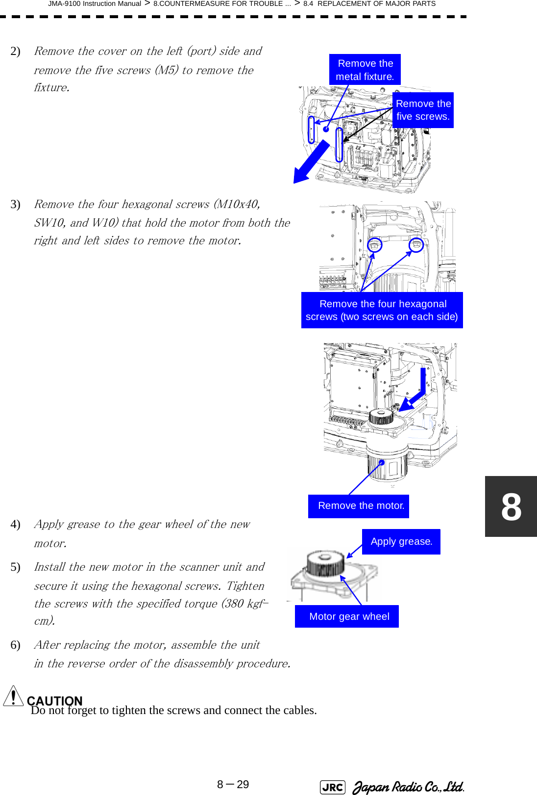
![JMA-9100 Instruction Manual > 8.COUNTERMEASURE FOR TROUBLE ... > 8.4 REPLACEMENT OF MAJOR PARTS8-3184) Attach the installation plate to the replacement motor. Do not forget to tighten the hexagonal bolts to an appropriate torque (210 kgf-cm) so they are free of looseness. 5) Install the motor into the scanner unit. Press the motor against the protrusions of the arm fixed to the motor on which the arm extends through the wall of the casing, adjust it to minimize backlash, and fix it in place.Do not forget to tighten the hexagonal bolts, to an appropriate torque (140 kgf-cm) so they are free of looseness.6) After having installed the motor, grease the gear wheel.7) After having replaced the motor, reassemble the unit by following the disassembly procedure in the reverse order.Do not forget to tighten the bolts and screws, and do not forget to reconnect the cables.8) 8.4.3.3 Scanner Unit NKE-2103[Required tools]•A Phillips screwdriver for 4 mm screw•A Phillips screwdriver for 5 mm screw•Single-ended wrench (width across flats 10 mm for M6 bolts)•Tools for removing the cover from the scanner unit.(Refer to the 8.4.2.3)Arm protrusionsPressTighten the four bolts.Grease here.](https://usermanual.wiki/Japan-Radio/NKE1130.Users-Manual-2/User-Guide-994638-Page-139.png)
![8-32JMA-9100 Instruction Manual > 8.COUNTERMEASURE FOR TROUBLE ... > 8.4 REPLACEMENT OF MAJOR PARTS[Replacement procedure]1) Open the upper cover (see Section 8.4.2.3) to remove the transmitter-receiver unit.2) Remove the hexagonal bolts (four M6 bolts) and remove the motor. Grease the gear wheel of the replacement motor and place it in the casing. Do not forget to tighten the hexagonal bolts to an appropriate torque (72 kgf-cm) so they are free of looseness.3) After having replaced the motor, reassemble the unit by following the disassembly procedure in the reverse order.Do not forget to tighten the bolts and screws, and do not forget to reconnect the cables.Clamp the cables so they do not interfere with the rotation of the motor's rotors.[Operation check]After you have completed the replacement work, follow the procedure below to check the operation.1) Turn on the radar and emit radar waves once the countdown is finished, and check that the radar image is correctly displayed. Check that the motor does not make any abnormal sound when it starts to rotate, while it is rotating, or when it stops. Remove the four bolts.](https://usermanual.wiki/Japan-Radio/NKE1130.Users-Manual-2/User-Guide-994638-Page-140.png)