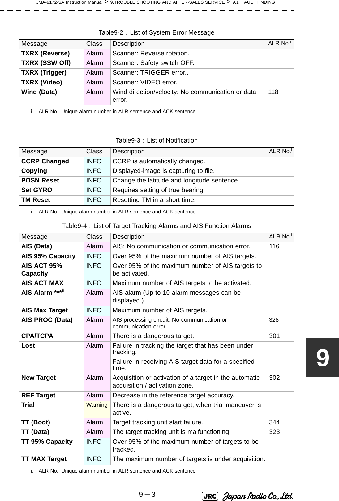
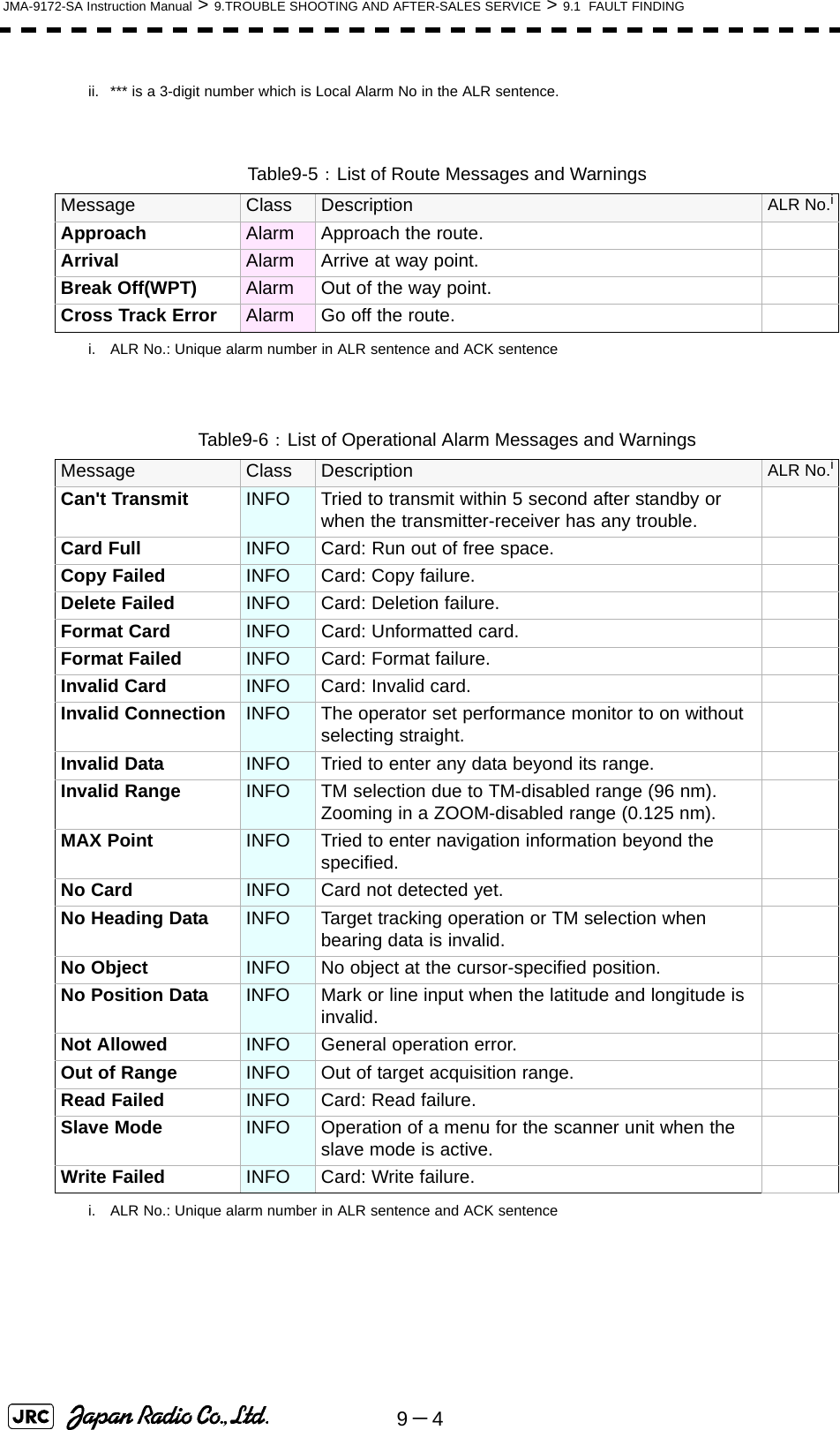
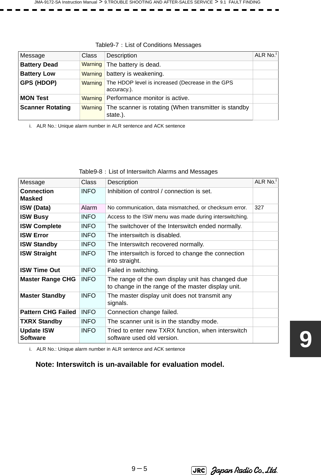
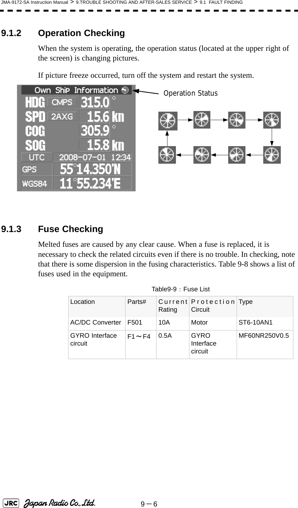
Japan Radio NKE1532 MARINE RADAR User Manual JMA 9100 series RADAR Instruction Manual
Japan Radio Co Ltd. MARINE RADAR JMA 9100 series RADAR Instruction Manual
UserManual.wiki
>
Japan Radio
>
NKE1532 User Manual
>
Users Manual 2
Contents
1.
Users Manual 1
2.
Users Manual 2
Users Manual 2
Navigation menu
Upload a User Manual
Namespaces
Wiki Guide
HTML
PDF
Info
Views
User Manual
Discussion / Help
Navigation
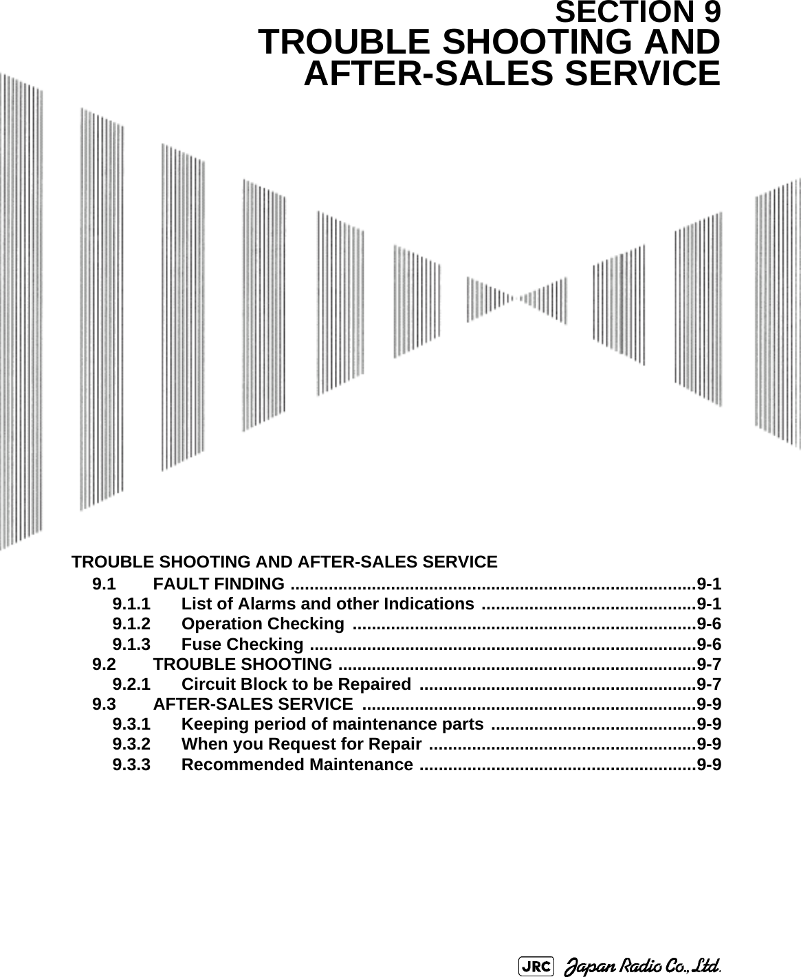
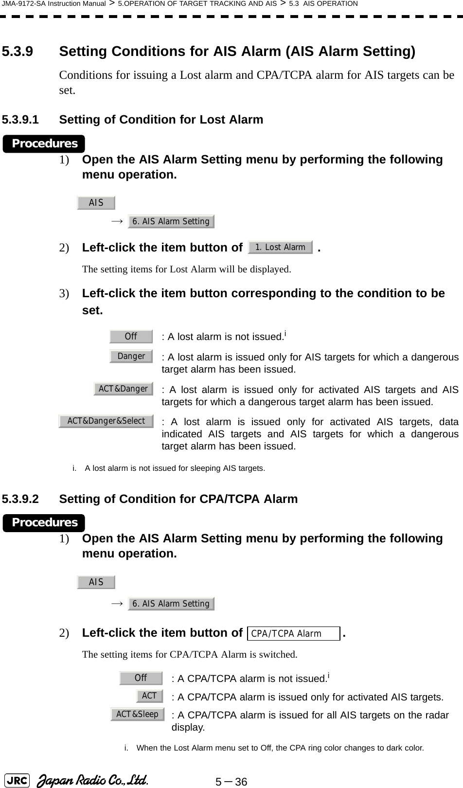
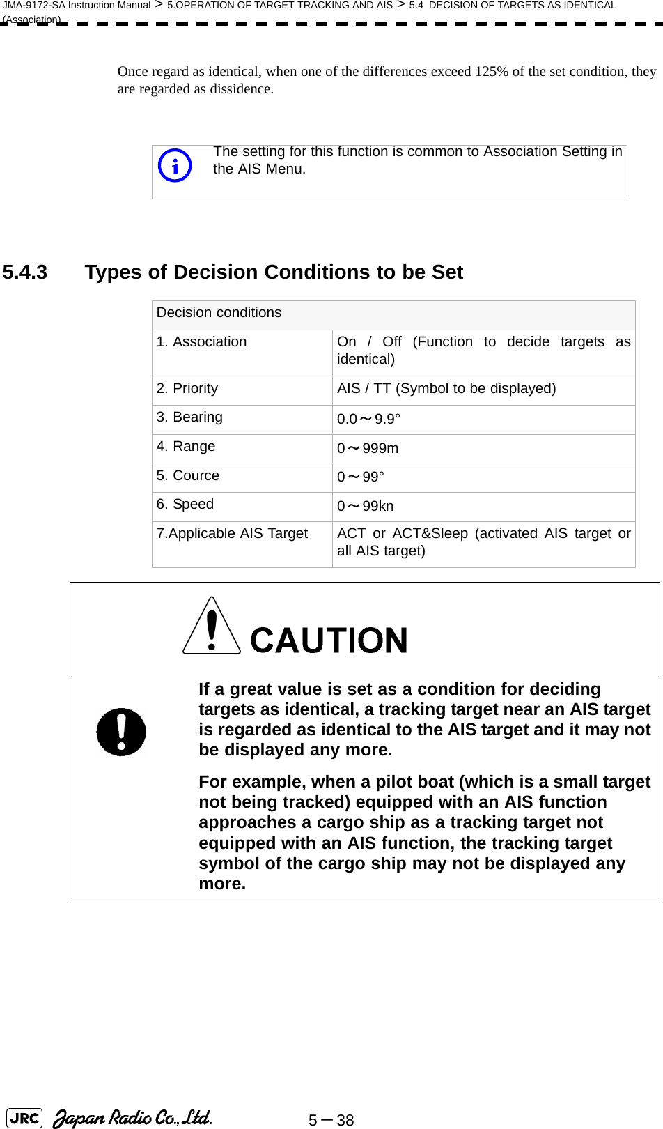
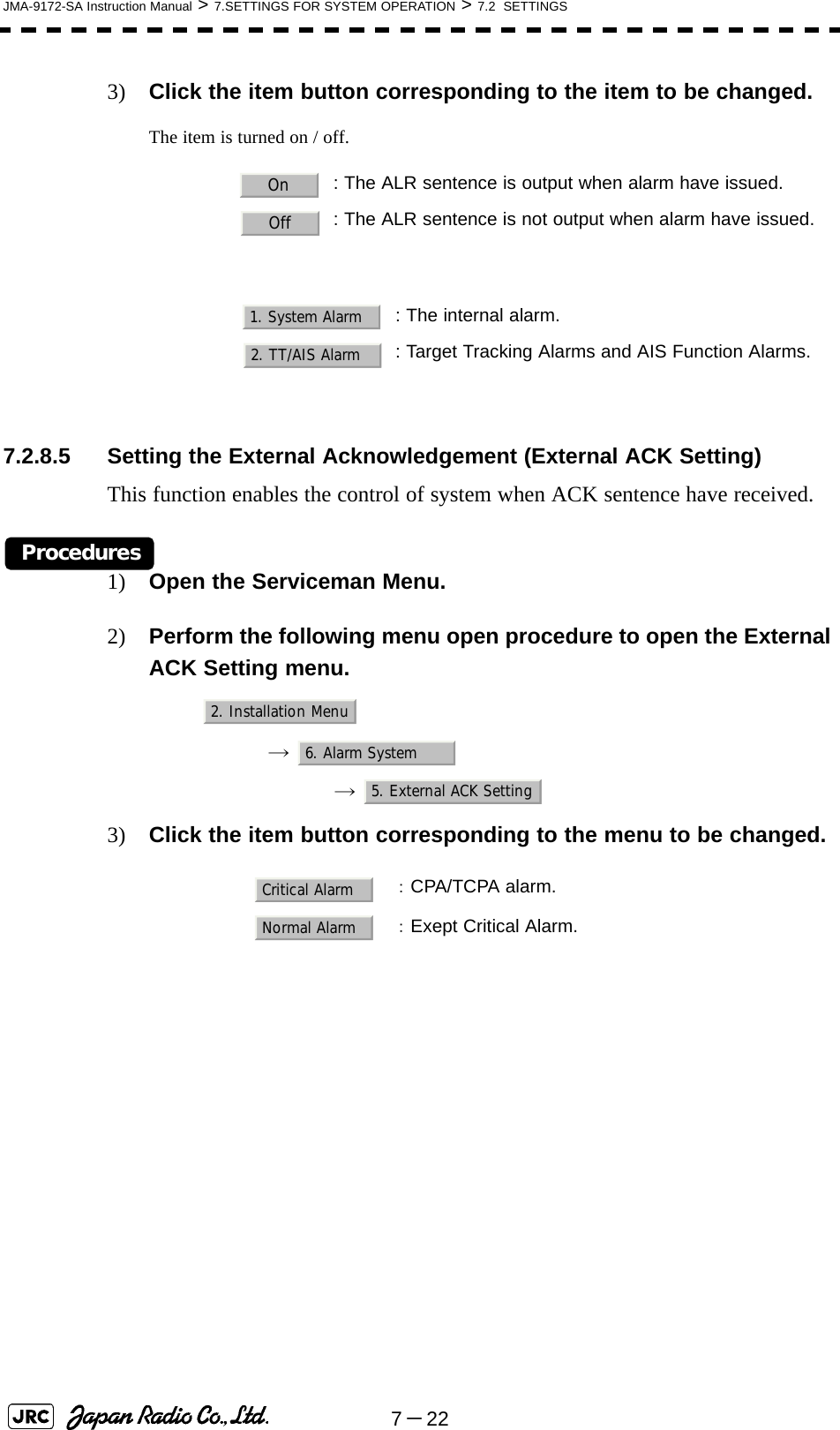
![5-34JMA-9172-SA Instruction Manual > 5.OPERATION OF TARGET TRACKING AND AIS > 5.3 AIS OPERATION4) Set an ending bearing and range by turning the [EBL] dial and [VRM] dial, and left-click.5.3.7.4 AIS Filter Display On/Off (Filter Display)Procedures1) Open the AIS Filter Setting menu by performing the following menu operation.→ 2) Left-click the item button of .Filter Display will be set to on or off.5.3.7.5 Display of Targets outside AIS Filter (Filter Mode)Procedures1) Open the Filter Mode menu by performing the following menu operation.→ 2) Left-click the item button of .iWhen the automatic activation function is enabled, the filterrange is automatically changed for covering the automaticactivation zone. Thus, the automatic activation zone is alwayswithin the filter range.: Displays only AIS targets in the AIS filter.: Displays AIS targets in the AIS filter by priority, and alsodisplays targets outside the AIS filter.iActivated AIS targets can be displayed even when they areoutside the AIS filter.AIS4. AIS Filter Setting3. Filter DisplayAIS4. AIS Filter Setting6. Filter ModeDisplayPriority](https://usermanual.wiki/Japan-Radio/NKE1532.Users-Manual-2/User-Guide-1404444-Page-1.png)
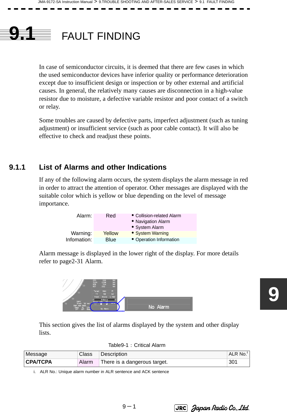
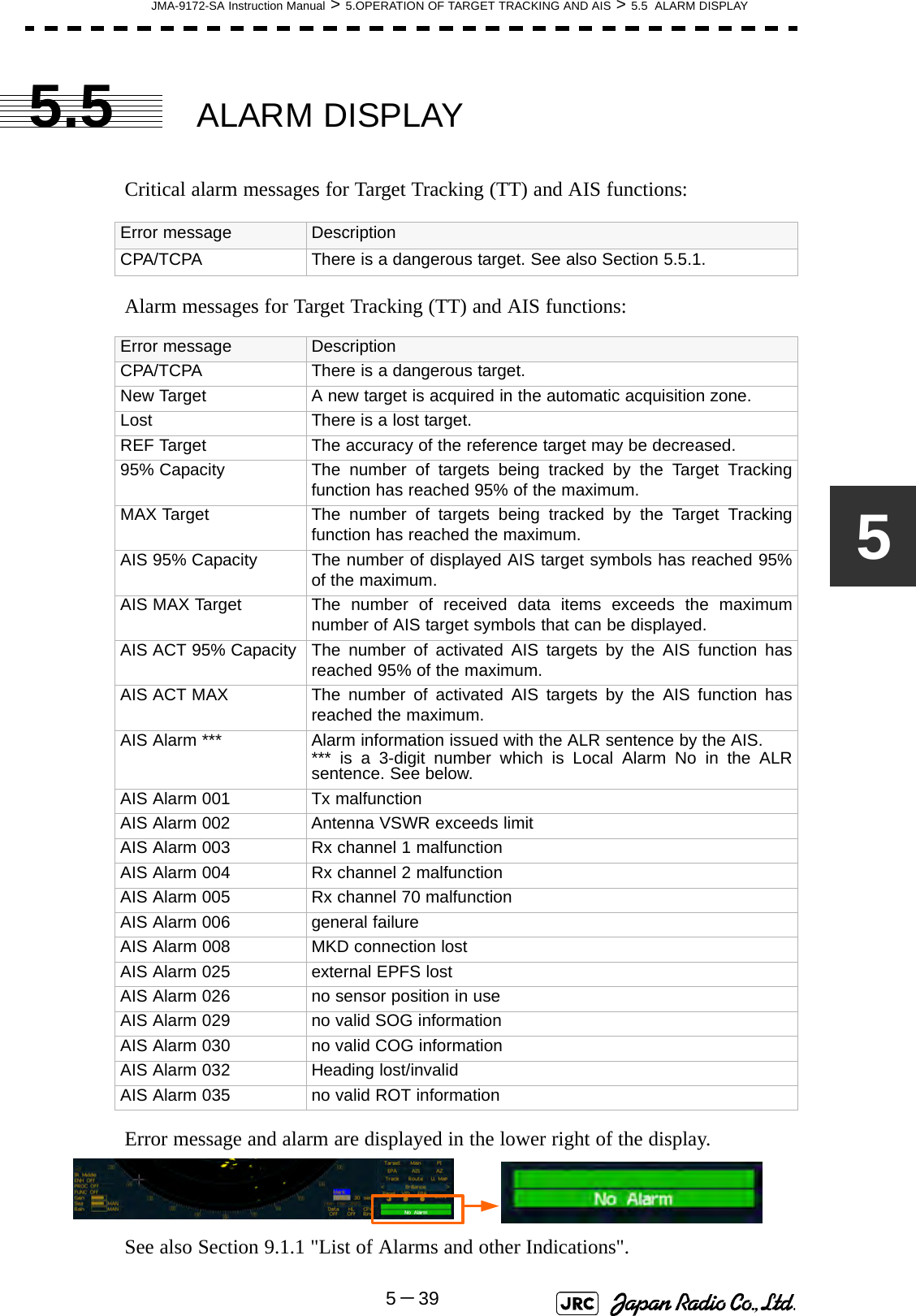
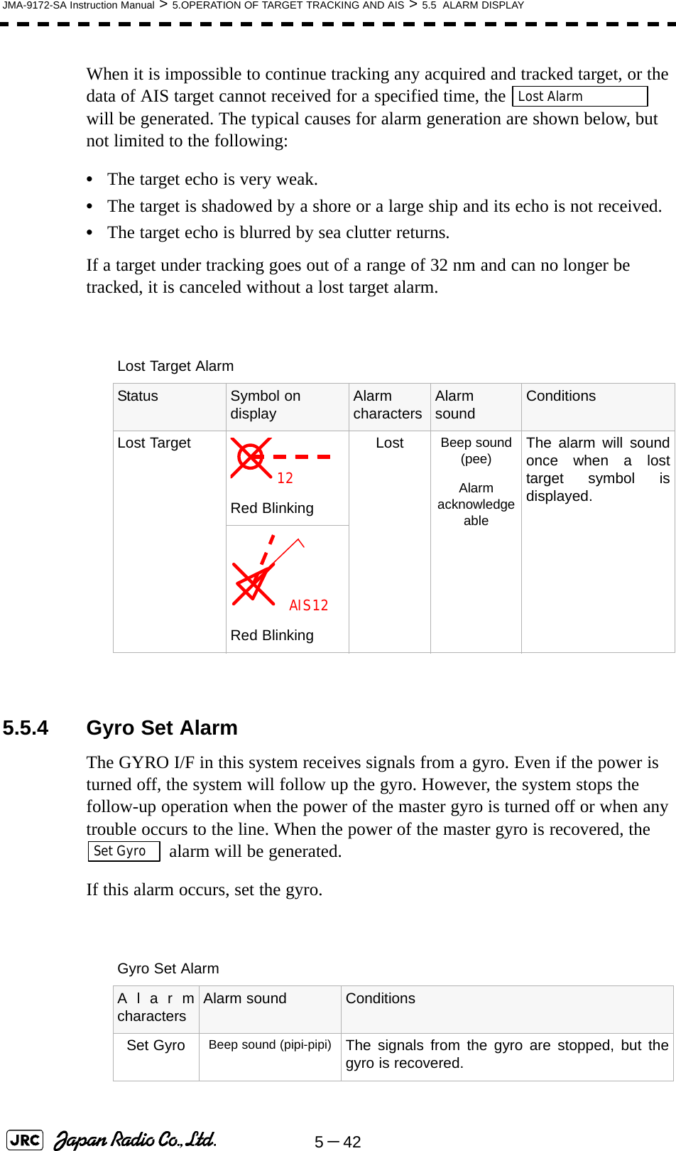
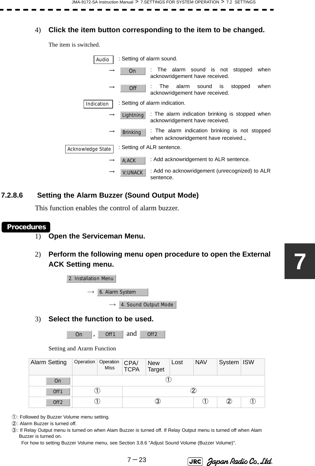
![JMA-9172-SA Instruction Manual > 5.OPERATION OF TARGET TRACKING AND AIS > 5.3 AIS OPERATION5-3555.3.7.6 Point FilterAIS targets which are not displayed because they are outside the AIS filter or at low priority levels can be activated by giving a higher priority to them.Procedures1) Put the cursor on the position where a point filter is to be set, and right-click to select the filter to be set.2) The setting items for cursor modes will be displayed.Left-click .A point filter will be set at the cursor position.If an AIS target is in the point filter, it will be activated.When an AIS target is activated or an AIS target is not found within one minute, the point filter will be cleared.5.3.8 Conditions for Deciding AIS Target to be LostAbout a lost targetWhen the data of an AIS target cannot be received for a specified time, the target is decided to be lost and the target data is deleted. As shown in the table below, the time until target data is deleted varies depending on the class of receive data and the target status.If the [ALARM ACK] key is pressed, the symbol is cleared. iThe point filter's range is 1 nm, and cannot be changed.Deciding AIS Target to be LostTarget status Time until data deletionSOLAS ship (Class A) SOLAS ship (Class B)Vessel below 3 knots (Class A) or 2 knots (Class B) and it is now at anchor or on the berth 18 min 18 minVessel of 3 knots or more and it is now at anchor or on the berth 60 sec 18 minVessel of 0 to 14 knots (Class B: 0 to 14 knots) 60 sec 180 secVessel of 14 to 23 knots 36 sec 180 secVessel of 23 knots or more 30 sec 180 secSAR (Search and Rescue) 60 sec 60 secATON (Aid to Navigation) 18 min 18 minBase Station 60 sec 60 seciWhen a dangerous target ship is lost, a lost alarm is issued and the symbolchanges to a lost symbol. The lost symbol will display continuously on thelast-received position.2. ACT AIS](https://usermanual.wiki/Japan-Radio/NKE1532.Users-Manual-2/User-Guide-1404444-Page-2.png)
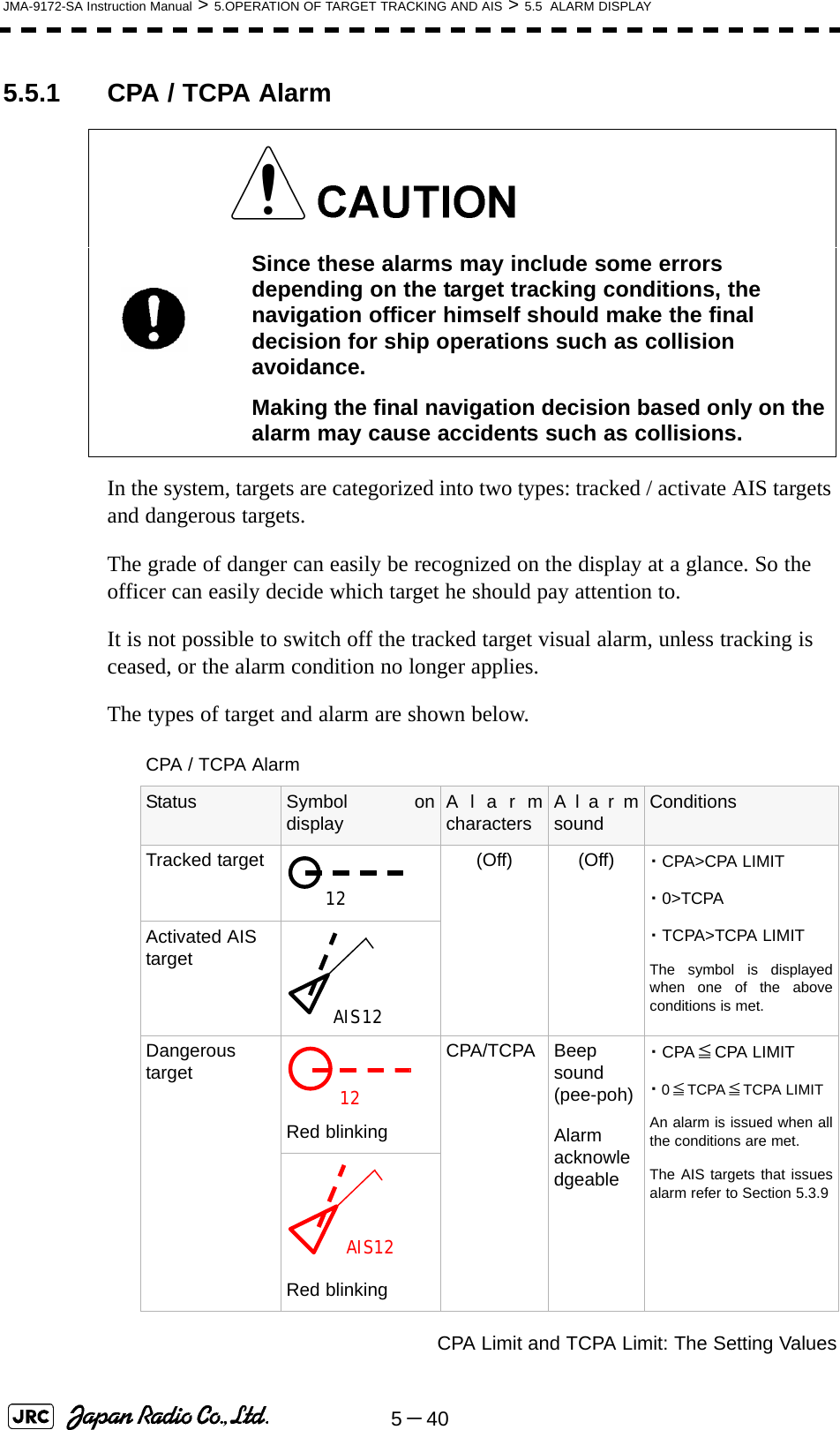
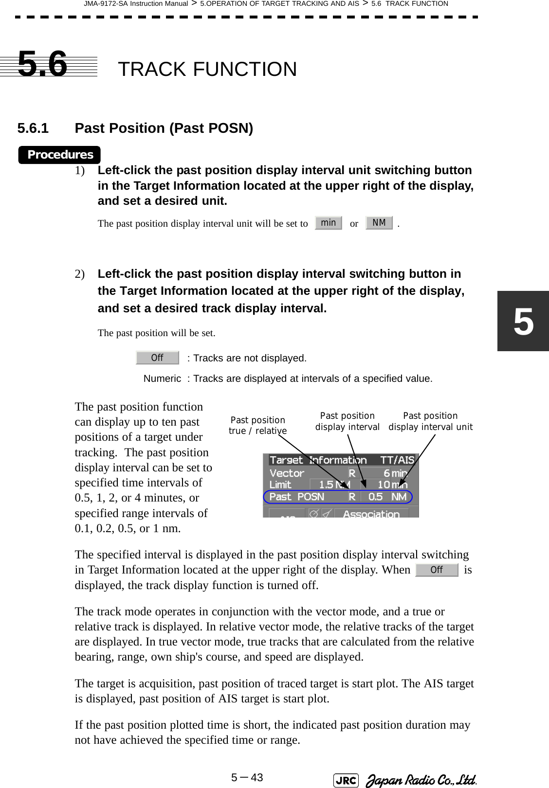
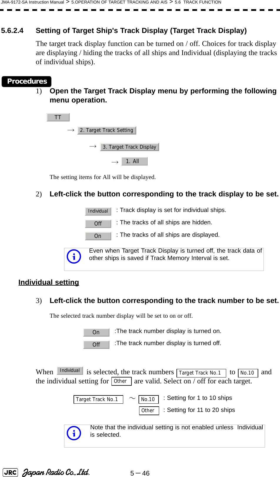
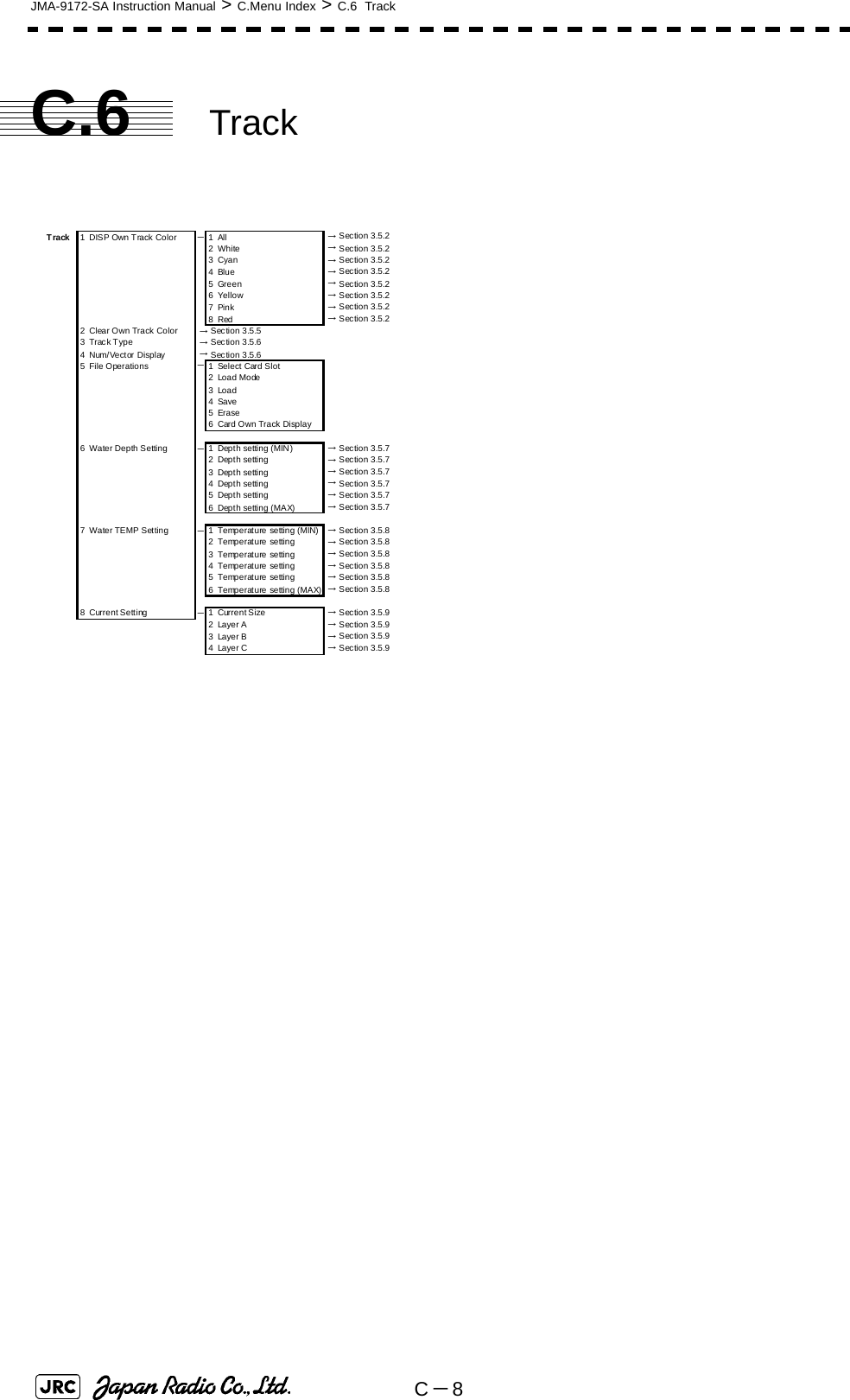
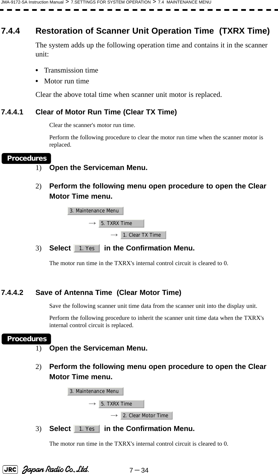
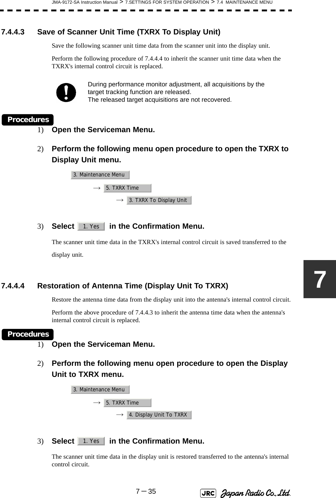
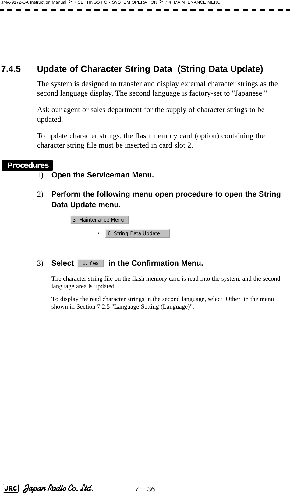
![JMA-9172-SA Instruction Manual > 5.OPERATION OF TARGET TRACKING AND AIS > 5.6 TRACK FUNCTION5-4755.6.2.5 Setting of Target Ship's Track Saving Interval (Track Memory Interval)An interval for saving target ship's track data can be set.Procedures1) Open the Track Memory Interval menu by performing the following menu operation.→ → 2) Left-click the button corresponding to the interval to be set.Select an interval from the following: 5.6.2.6 Clear of Target Ship's Track (Clear Track)The target ship's track can be cleared by setting a color or a track number.[1] Clear of Tracks by Setting Color (Clear Track Color)Procedures1) Open the Clear Track Color menu by performing the following menu operation.→ → The setting items for Clear Track Color will be displayed.iThis function is not available when the Target Track Function isturned off.Off/3sec/5sec/10sec/30sec/1min/3min/5min/10min/30min/60min/1NM/3NM/5NM/10NMiIf Card T.TRK Display is used, target ship's tracks displayedthrough the card cannot be cleared.TT2. Target Track Setting4. Track Memory IntervalTT2. Target Track Setting5. Clear Track Color](https://usermanual.wiki/Japan-Radio/NKE1532.Users-Manual-2/User-Guide-1404444-Page-14.png)
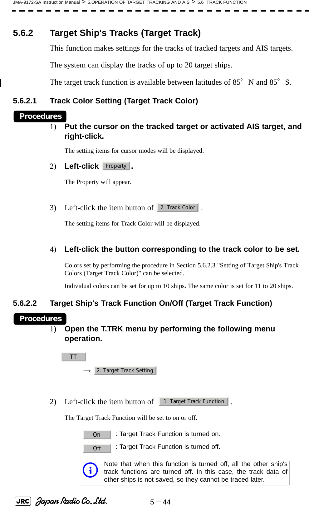
![5-48JMA-9172-SA Instruction Manual > 5.OPERATION OF TARGET TRACKING AND AIS > 5.6 TRACK FUNCTION2) Left-click the button corresponding to the color of the target tracks to be cleared.The Confirmation Window will appear.3) Left-click to clear the track line.All the tracks of the selected color will be cleared.[2] Clear of Tracks by Setting Track Number (Clear Track Number)Procedures1) Open the T.TRK menu by performing the following menu operation.→ → The setting items for Clear Track Number will be displayed.2) Left-click the button corresponding to the number of the tracks to be cleared.The Confirmation Window will appear.3) Left-click to clear the track line.The tracks of the selected number will be cleared. 5.6.2.7 Operation of Target Ship's Track Data Saved on Card (FileOperations)Target ship's track data can be saved on a flash memory card and read from the card.iData can be saved to a flash memory card until the cardbecomes full, but the number of files that can be read anddisplayed is limited to 64 in alphanumeric order. When thenumber of files has reached 64, delete unnecessary files.1. YesTT2. Target Track Setting6. Clear Track Number1. Yes](https://usermanual.wiki/Japan-Radio/NKE1532.Users-Manual-2/User-Guide-1404444-Page-15.png)
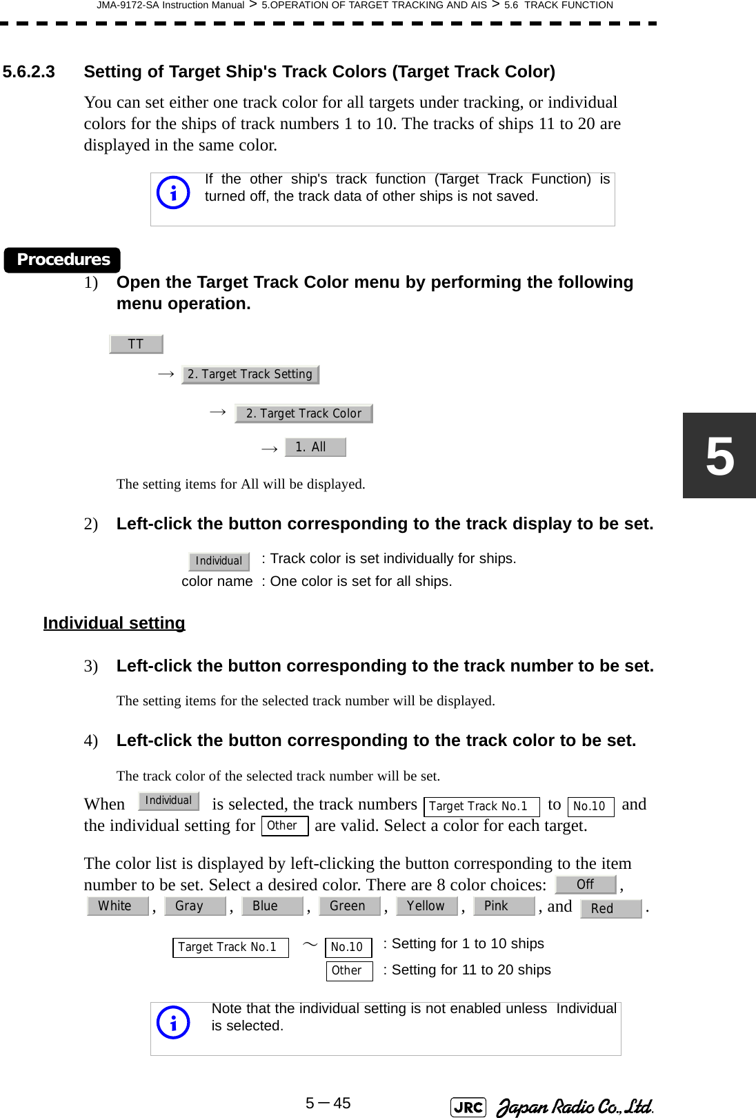
![JMA-9172-SA Instruction Manual > 5.OPERATION OF TARGET TRACKING AND AIS > 5.6 TRACK FUNCTION5-495[1] Loading File (Load)Procedures1) Insert a flash memory card into the card slotFlash memory card (option) is necessary.2) Open the File Operations menu by performing the following menu operation.→ → 3) Left-click the item button of to select a card slot.The setting item for Select Card Slot is switched between Slot1 and Slot2.4) Left-click the item button of to select Add or Overwrite. The setting item for Load Mode is switched between and .When is selected, new data is added to the current data on the card. When is selected, new data is saved over the current data on the card.5) Left-click .Currently saved target ship's track data will be listed.6) Left-click the button corresponding to the file to be loaded.The Confirmation Window will appear.7) Left-click to load the file.The selected target track data will be loaded and shown on the radar display.TT2. Target Track Setting7. File Operations1. Select Card Slot2. Load ModeAddOverwriteAddOverwrite3. Load1. Yes](https://usermanual.wiki/Japan-Radio/NKE1532.Users-Manual-2/User-Guide-1404444-Page-16.png)
![5-50JMA-9172-SA Instruction Manual > 5.OPERATION OF TARGET TRACKING AND AIS > 5.6 TRACK FUNCTION[2] Saving File (Save)Procedures1) Insert a flash memory card into the card slot.Flash memory card (option) is necessary.2) Open the File Operations menu by performing the following menu operation.→ → 3) Left-click the item button of to select a card slot.The setting item for Select Card Slot is switched between Slot1 and Slot2.4) Left-click . The Input File Name menu will appear.5) Input the file name to be saved.Up to ten characters can be input as a file name.For inputs to the characters input screen, refer to Section 3.3.4.7 "Entering a character". After the input, the Confirmation Window will appear.6) Left-click to save the file.The currently displayed target track data will be saved. TT2. Target Track Setting7. File Operations1. Select Card Slot4. Save1. Yes](https://usermanual.wiki/Japan-Radio/NKE1532.Users-Manual-2/User-Guide-1404444-Page-17.png)
![JMA-9172-SA Instruction Manual > 5.OPERATION OF TARGET TRACKING AND AIS > 5.6 TRACK FUNCTION5-515[3] Erasing File (Erase)Procedures1) Insert the flash memory card into the card slot.Flash memory card (option) is necessary.2) Open the File Operations menu by performing the following menu operation.→ → 3) Left-click the item button of to select a card slot.The setting item for Select Card Slot is switched between Slot1 and Slot2.4) Left-click .The Erase menu will appear.Currently saved target ship's track data on the card will be listed.5) Left-click the button corresponding to the file to be erased.The Confirmation Window will appear.6) Left-click to erase the file.The selected target track data will be erased and the file name will disappear from the list.TT2. Target Track Setting7. File Operations1. Select Card Slot5. Erase1. Yes](https://usermanual.wiki/Japan-Radio/NKE1532.Users-Manual-2/User-Guide-1404444-Page-18.png)
![5-52JMA-9172-SA Instruction Manual > 5.OPERATION OF TARGET TRACKING AND AIS > 5.6 TRACK FUNCTION[4] Displaying File (Card Target Track Display)Procedures1) Insert the flash memory card into the card slot.Flash memory card (option) is necessary.2) Open the File Operations menu by performing the following menu operation.→ → 3) Left-click the item button of to select a card slot. The setting item for Select Card Slot is switched between Slot1 and Slot2.4) Left-click . The Card T.TRK Display menu will appear.Currently saved target ship's track data on the card will be listed.5) Left-click the button corresponding to the file to be displayed.The Confirmation Window will appear.6) Left-click to display the T.TRK line.The selected file will be highlighted, and the currently saved target track data will be displayed.Cancel1) Open the Card T.TRK Display window.The displayed file is highlighted.2) Left-click the button corresponding to the displayed file.The file will be deselected and returned to normal display.TT2. Target Track Setting7. File Operations1. Select Card Slot6. Card T.TRK Display1. Yes](https://usermanual.wiki/Japan-Radio/NKE1532.Users-Manual-2/User-Guide-1404444-Page-19.png)
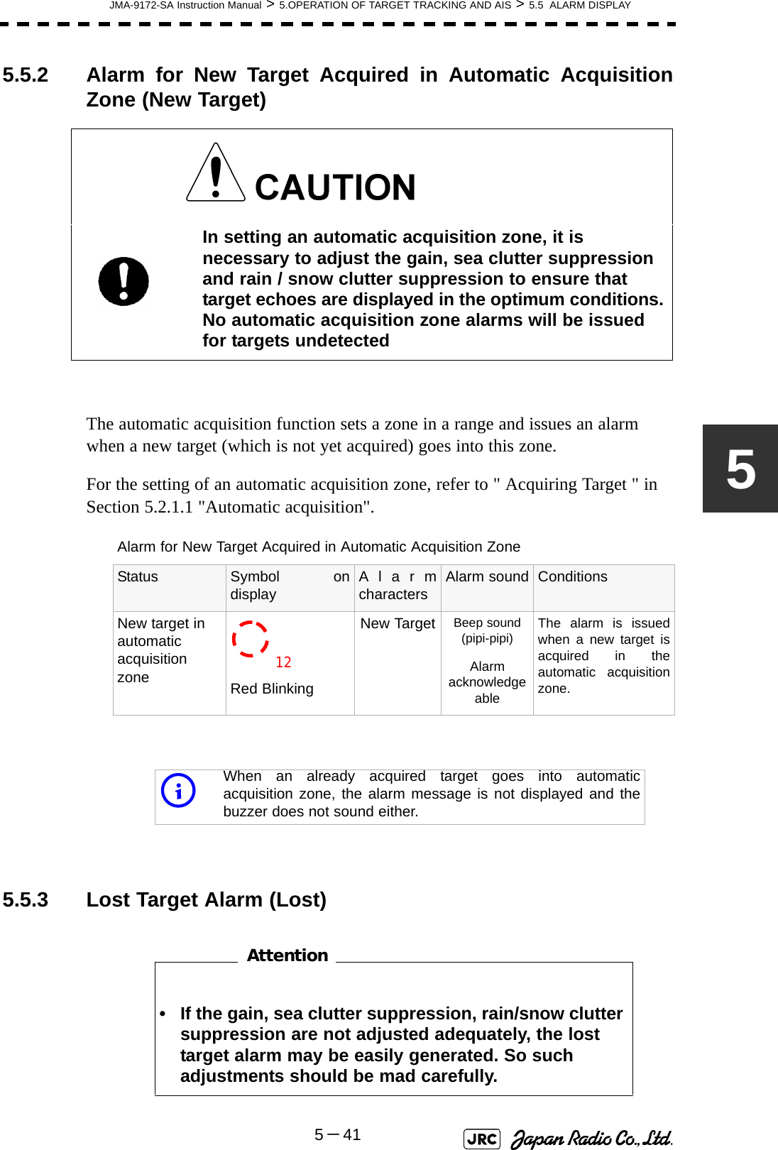
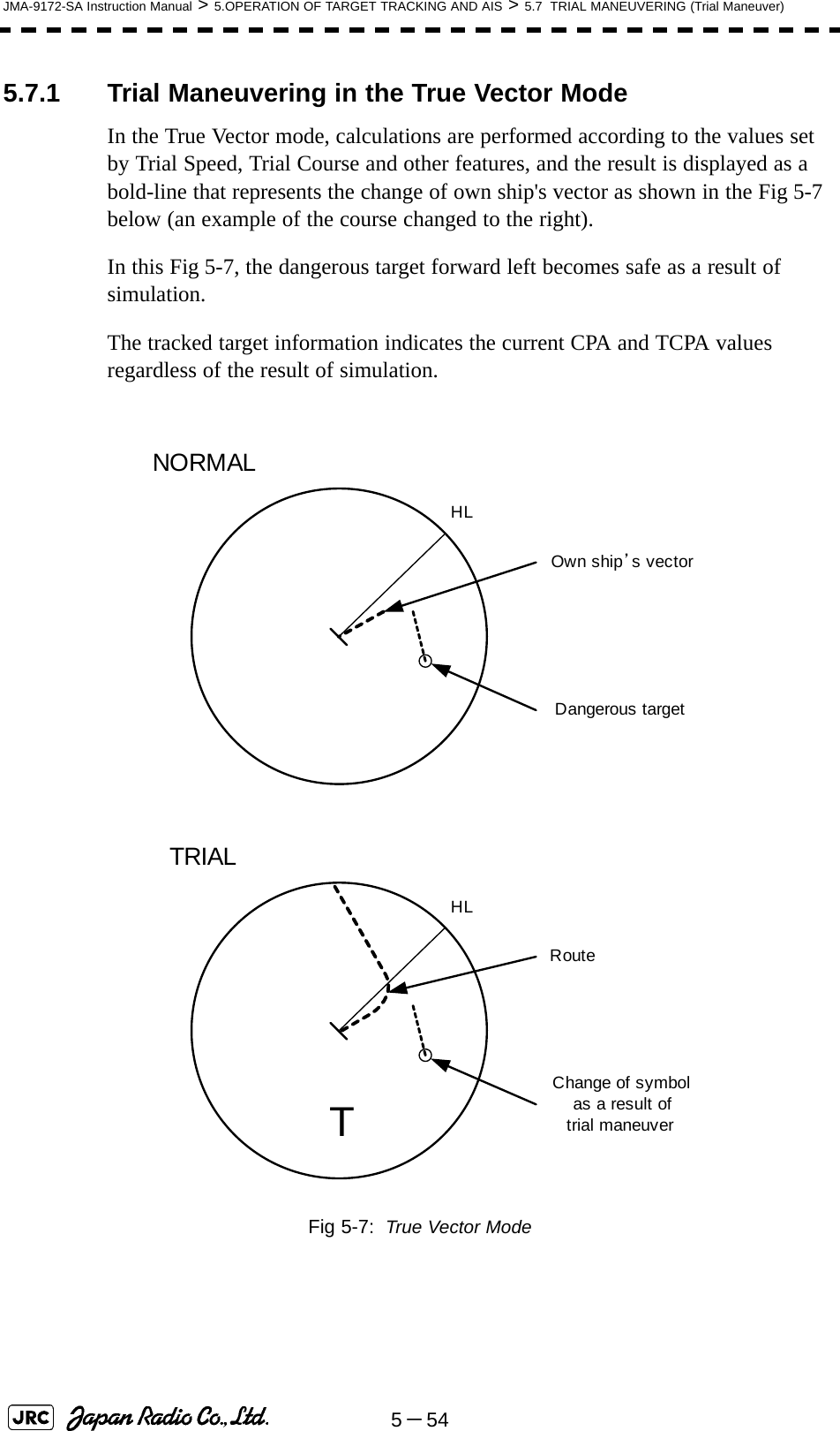
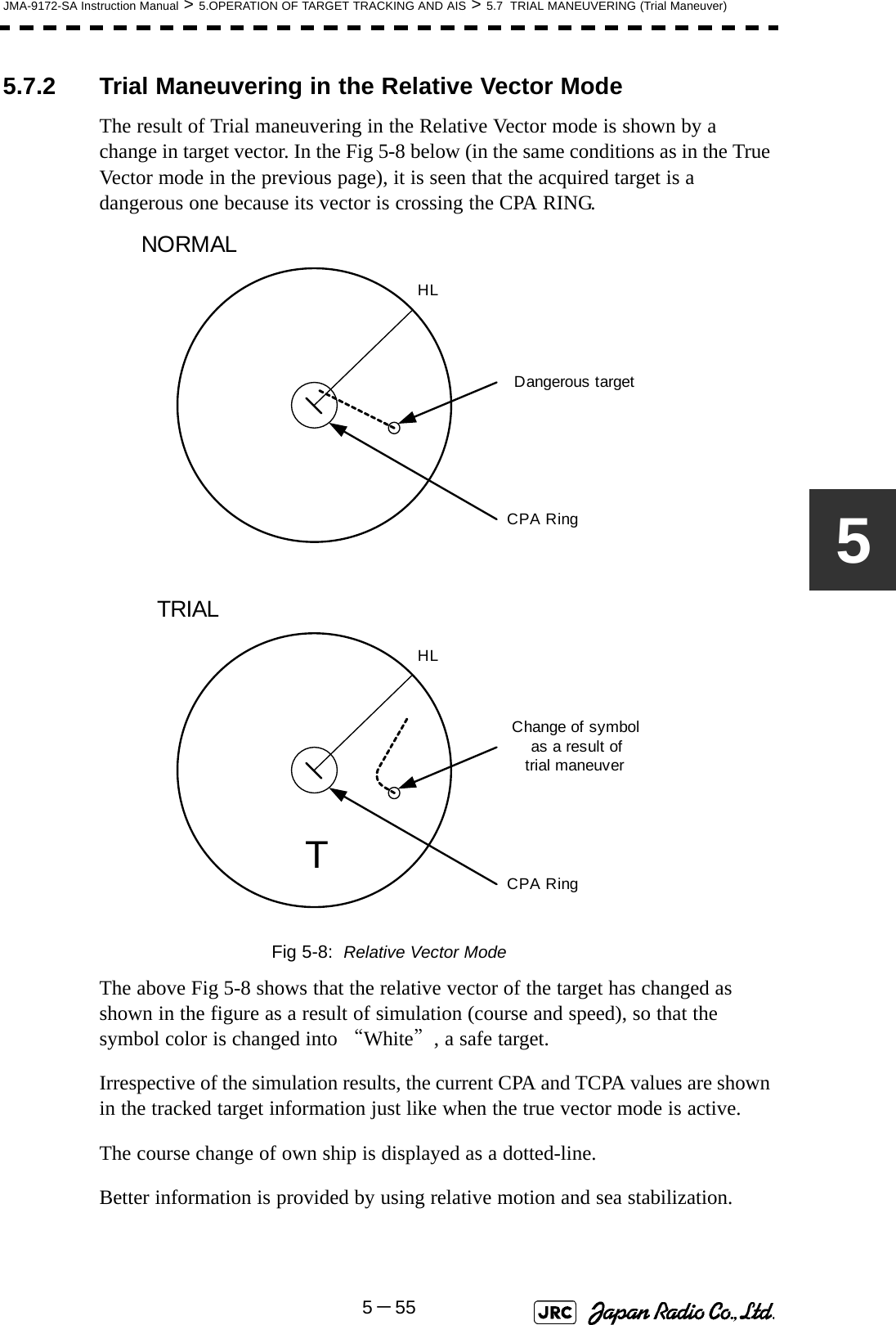
![JMA-9172-SA Instruction Manual > 5.OPERATION OF TARGET TRACKING AND AIS > 5.7 TRIAL MANEUVERING (Trial Maneuver)5-5355.7 TRIAL MANEUVERING (Trial Maneuver) The trial maneuvering is the function of simulating own ship’s course and speed for collision avoidance when a dangerous target appears. When the own ship's course and speed are entered in manual mode, the trial maneuvering function checks if pre-acquired or pre-activated targets are dangerous.The ranges of course and speed to be entered manually:• Trial maneuvering is to simulate own ship’s course and speed in the conditions that the course and speed of a target ship are unchanged as they are. As the situation is different from any actual ship maneuvering, set values with large margins to CPA Limit and TCPA Limit.Course: 360° (in 0.1° intervals) ............................................... [EBL] dialSpeed: 0 to 100kn (in 0.1kn step)........................................ [VRM] dialAttention](https://usermanual.wiki/Japan-Radio/NKE1532.Users-Manual-2/User-Guide-1404444-Page-20.png)
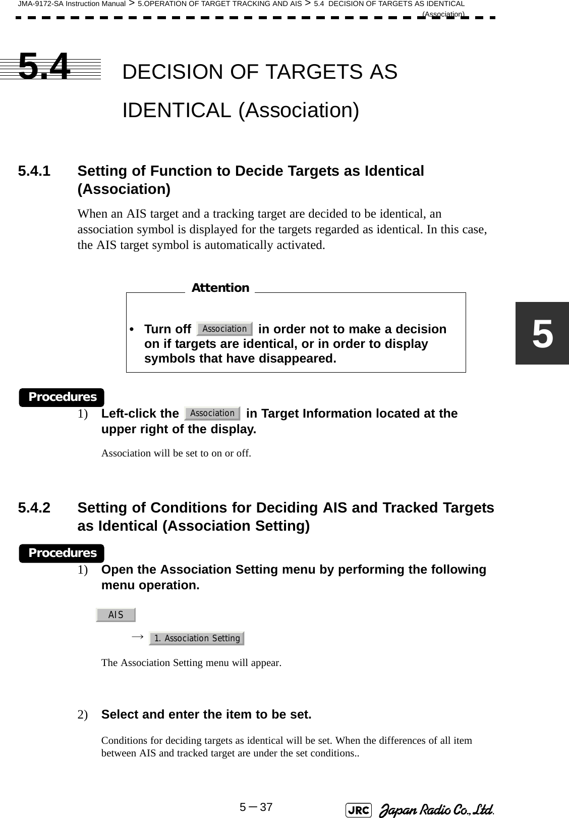
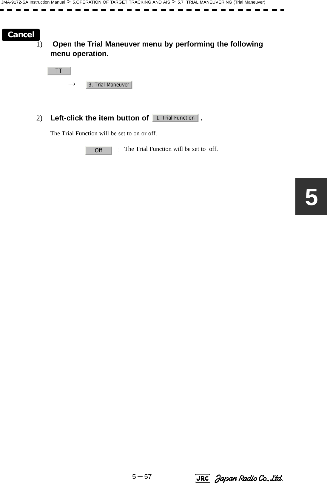
![5-56JMA-9172-SA Instruction Manual > 5.OPERATION OF TARGET TRACKING AND AIS > 5.7 TRIAL MANEUVERING (Trial Maneuver)5.7.3 Operation of Trial Maneuvering FunctionProcedures1) Open the Trial Maneuver menu by performing the following menu operation.→ 2) Left-click the item button of .The Trial Function will be set to on or off.When the Trial Function is active, the character " T " will display at the bottom of the radar display.3) Set values for Course by turning the [EBL] dial, and for Speed by turning the [VRM] dial.4) Set other characteristics.For inputs to the value input screen, refer to Section 3.3.4.2 "Directly entering a numeric value".Dangerous target symbols are displayed in red and safe target symbols in white.: The trial maneuvering function is turned on.: The trial maneuvering function is turned off.: Vector time (1 to 60 min): Time until trial maneuvering is started (0 to 30 min): Dynamic trait of the own ship→ : Range from when steered to when the shipbeings to turn (0 to 2000 m)→ : Turning radius (0.10 to 2.00 nm)→ : Acceleration (0.0 to 100 knots/min)→ : Deceleration (0.0 to 100 knots/min)iVector Time is valid only when Trial Function is set to on. If it is off, the vector timebefore trial maneuvering is displayed.Time until the start of trial maneuvering is counted down immediately after the input.The acceleration and deceleration are influenced depending on the relationshipbetween the current speed and the input speed for trial maneuvering.If 0.0 kn/min is set for Acceleration when the speed for trial maneuvering is fasterthan the current speed, or for Deceleration when the speed for trial maneuvering isslower than the current speed, the system performs simulation on the assumptionthat the speed is changed immediately after the time set for Time to Maneuver .TT3. Trial Maneuver1. Trial FunctionOnOffVector TimeTime to ManeuverOwn Ship Dynamic TraitReachTurn RadiusAccelerationDecceleration](https://usermanual.wiki/Japan-Radio/NKE1532.Users-Manual-2/User-Guide-1404444-Page-23.png)

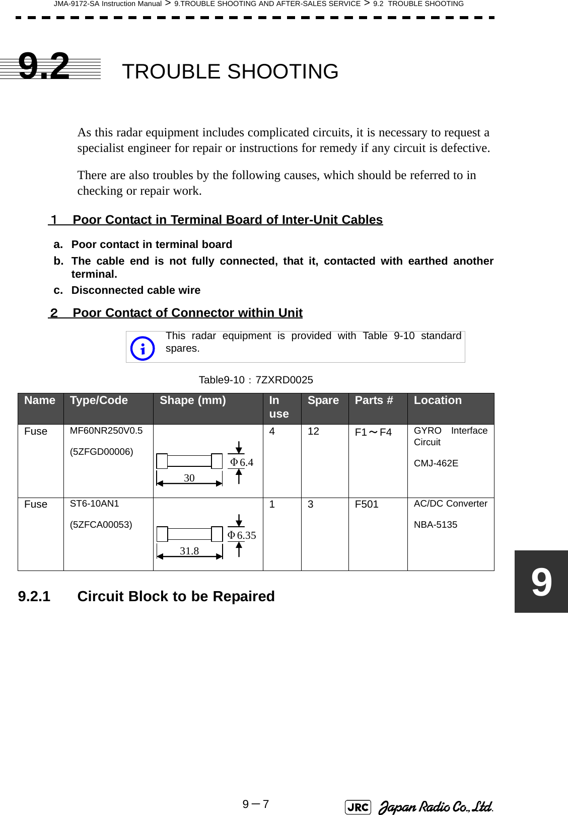
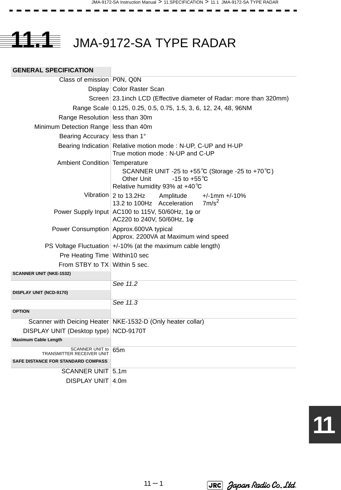
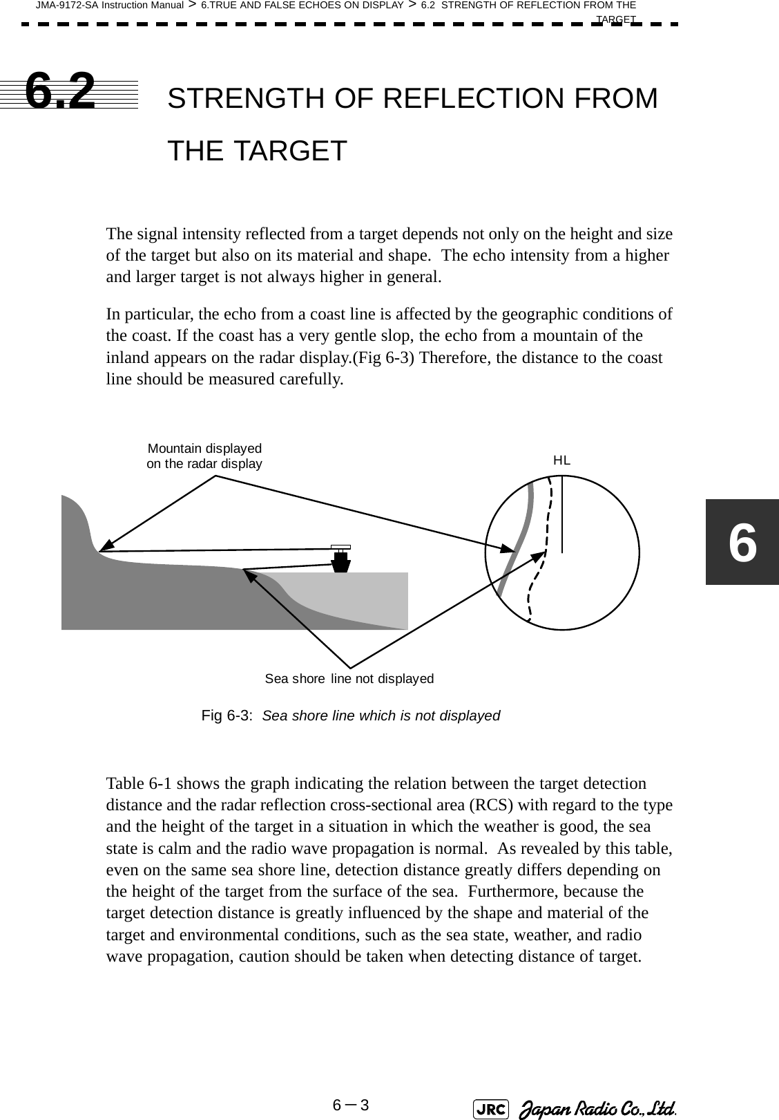
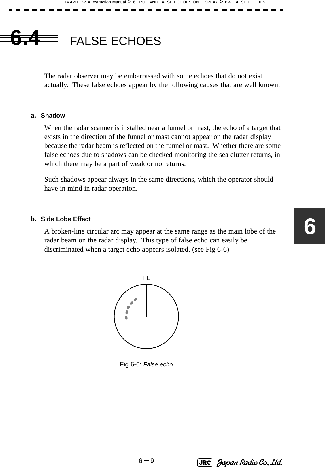
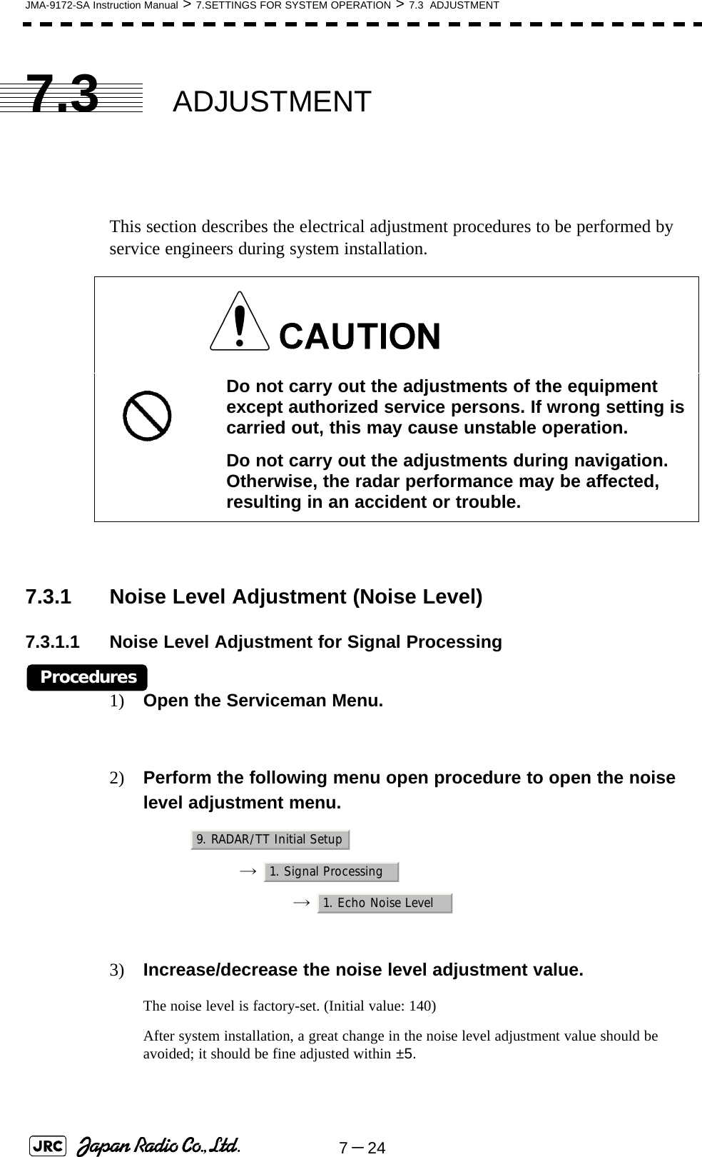
![JMA-9172-SA Instruction Manual > 6.TRUE AND FALSE ECHOES ON DISPLAY > 6.1 RADAR WAVE WITH THE HORIZON6-16The radar operator has a role of interpreting the radar displays to provide his best aid in maneuvering the ship. For this purpose, the operator has to observe the radar displays after fully understanding the advantages and disadvantages that the radar has. For better interpretation of radar display, it is important to gain more experiences by operating the radar equipment in fair weathers and comparing the target ships watched with the naked eyes and their echoes on the radar display.The radar is mainly used to monitor the courses of own ship and other ships in open seas, to check buoys and other nautical marks when entering a port, to measure own ship’s position in the coastal waters relative to the bearings and ranges of the shore or islands using a chart, and to monitor the position and movement of a heavy rain if it appears on the radar display.Various types of radar display will be explained below.6.1 RADAR WAVE WITH THE HORIZONRadar beam radiation has the nature of propagating nearly along the curved surface of the earth. The propagation varies with the property of the air layer through which the radar beam propagates. In the normal propagation, the distance (D) of the radar wave to the horizon is approximately 10% longer than the distance to the optical horizon. The distance (D) is given by the following formula: [NM]: Height (m) of radar scanner above sea level: Height (m) of a target above sea levelFig 6-2 is a diagram for determining the maximum detection range of a target that is limited by the curve of the earth surface in the normal propagation.Fig 6-1: RADAR wave with the horizonD2.23h1h2+()=h1h2DEarthh1h2Radar Targets](https://usermanual.wiki/Japan-Radio/NKE1532.Users-Manual-2/User-Guide-1404444-Page-28.png)
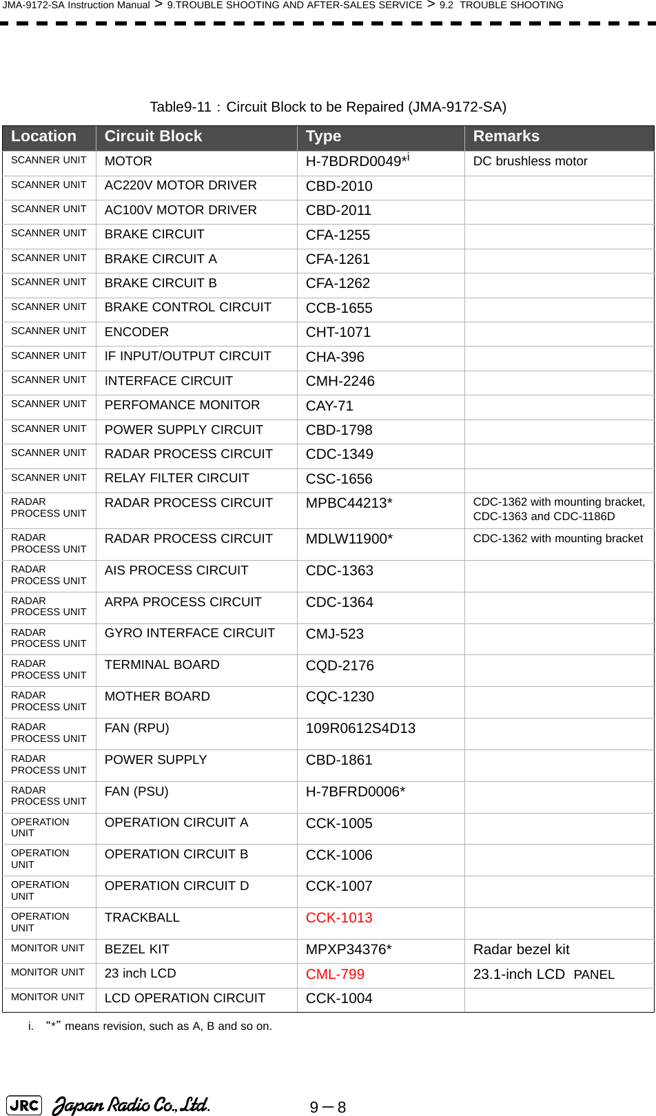
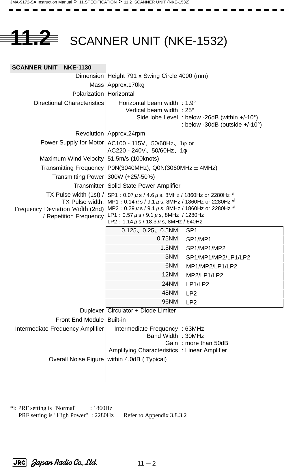
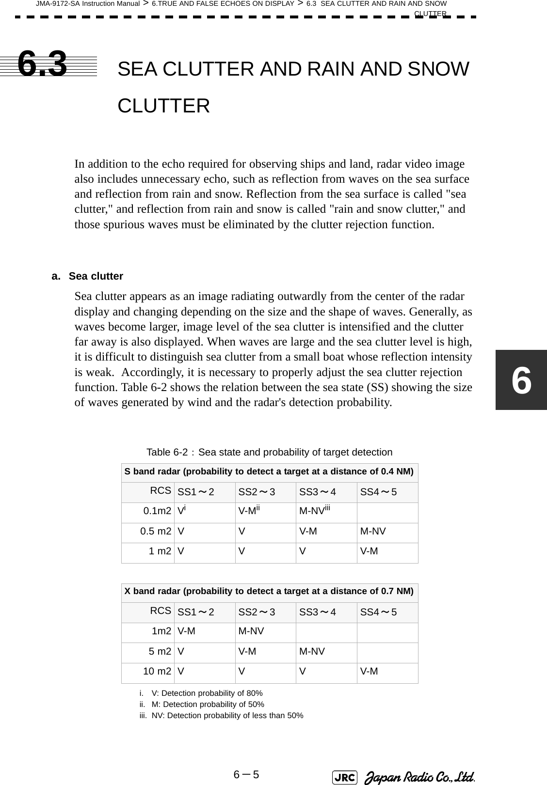
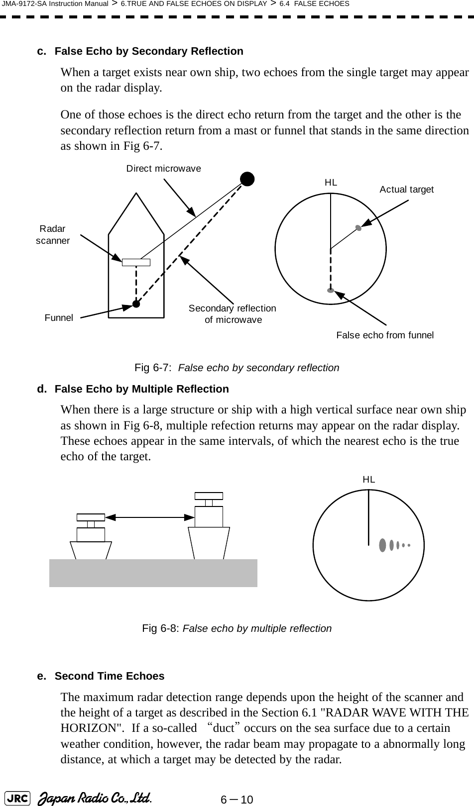
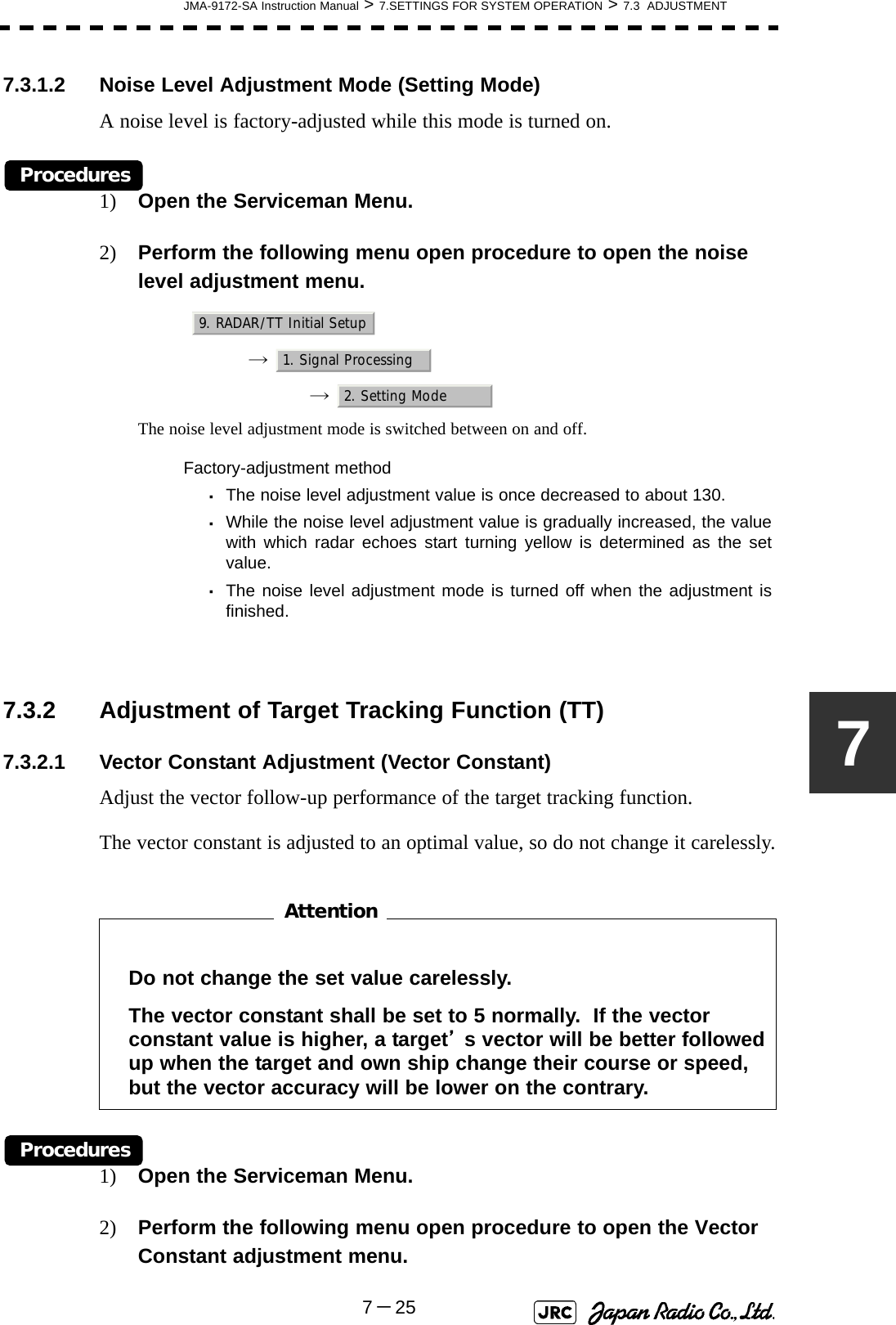
![6-2JMA-9172-SA Instruction Manual > 6.TRUE AND FALSE ECHOES ON DISPLAY > 6.1 RADAR WAVE WITH THE HORIZON Fig 6-2: Maximum detection range of a targetWhen the height of own ship’s scanner is 10 m for instance,i. A target that can be detected at the radar range of 64 nm on the radar displayis required to have a height of 660 m or more.ii. If the height of a target is 10 m, the radar range has to be approx. 15 nm.However, the maximum radar range at which a target can be detected on theradar display depends upon the size of the target and the weather conditions,that is, the radar range may increase or decrease depending upon thoseconditions. Height of RADAR Scanner Detective Range Height of TargetD[NM]](https://usermanual.wiki/Japan-Radio/NKE1532.Users-Manual-2/User-Guide-1404444-Page-29.png)
![6-4JMA-9172-SA Instruction Manual > 6.TRUE AND FALSE ECHOES ON DISPLAY > 6.2 STRENGTH OF REFLECTION FROM THE TARGET Table 6-1: Relation between type and height of target and detection distance and RCSType of target Height from sea surface (m)Detection distance (NM) RCS X band S band X band S bandSea shore line 60 20 20 50,000 50,000Sea shore line 6 8 8 5000 5000Sea shore line 3 6 6 2500 2500SOLAS target ship (>5000GT) 10 11 11 50,000 30,000SOLAS target ship (>500GT) 5 8 8 1800 1000Small boat with IMO standard compatible radar reflector 45.03.77,50,5Marine buoy with corner reflector 3,5 4.9 3.6 10 1Standard marine buoy 3,5 4.6 3.0 5 0,510-meter small boat without radar reflector 23.43.02,51,4Waterway location beacon 1 2.0 1.0 1 0,1Detection distance shown in the above table may greatlydecrease depending on the shape of the target, sea state,weather and radio wave propagation conditions.m2[]i](https://usermanual.wiki/Japan-Radio/NKE1532.Users-Manual-2/User-Guide-1404444-Page-31.png)
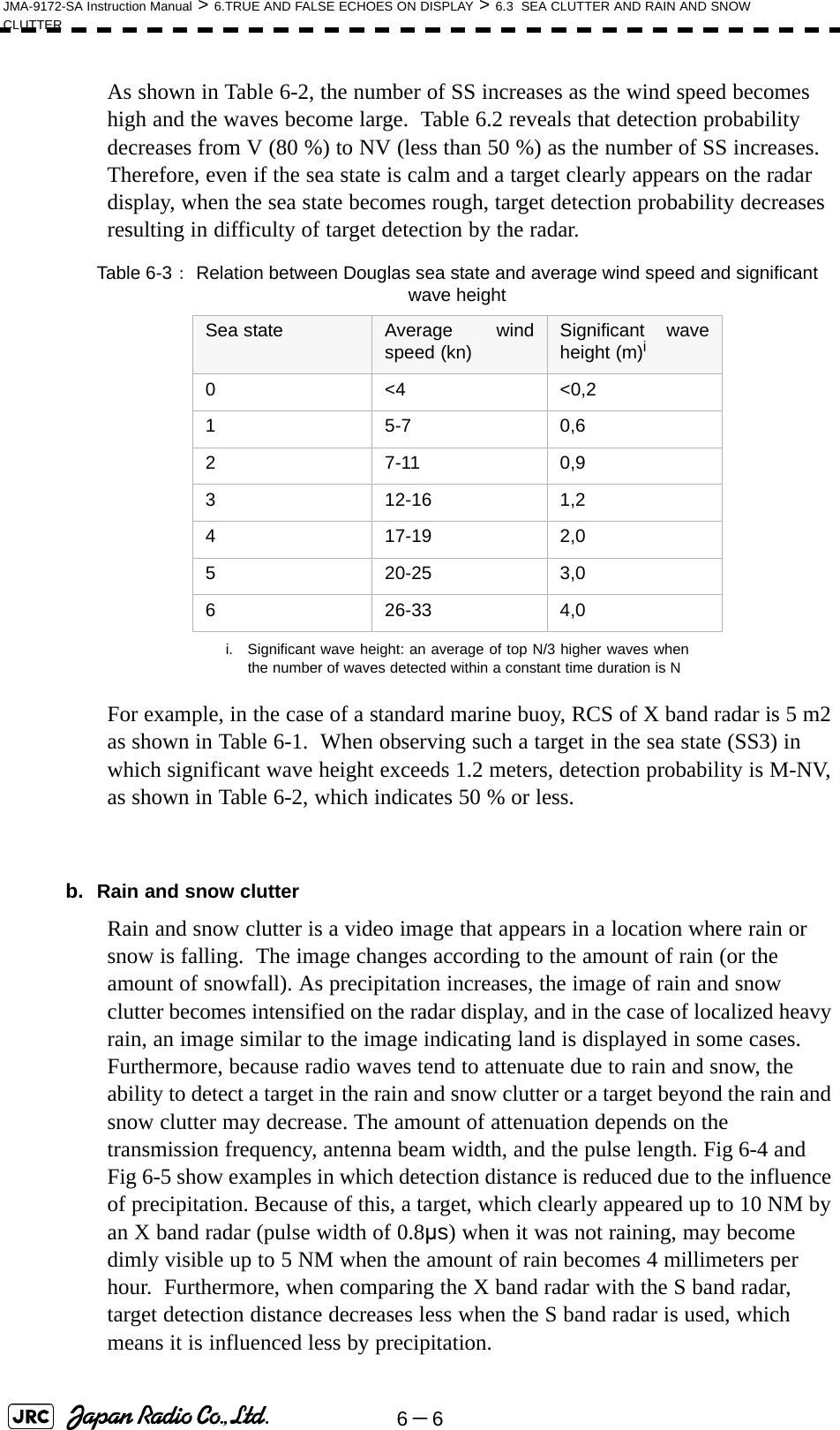
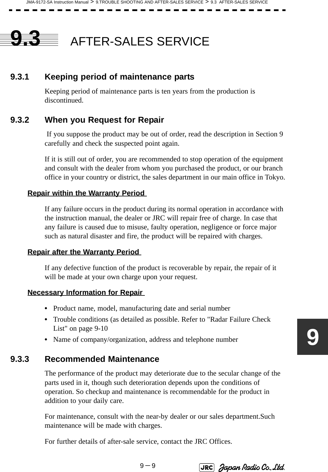
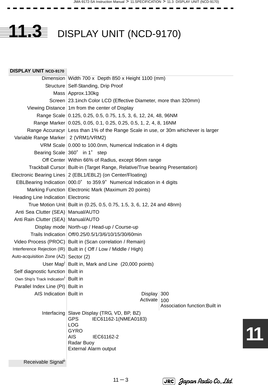
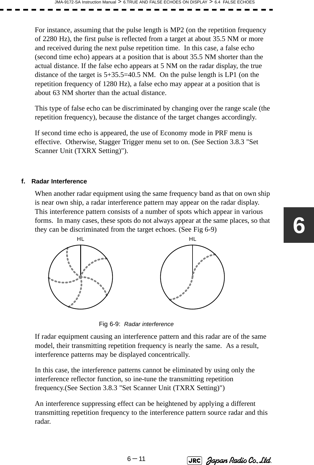
![JMA-9172-SA Instruction Manual > 6.TRUE AND FALSE ECHOES ON DISPLAY > 6.3 SEA CLUTTER AND RAIN AND SNOWCLUTTER6-76 02468101214160 2 4 6 81012 14 16降雨時の検出距離 (NM) 雨の降っていないときの検出距離(NM) 16mm/hr の降雨時 パルス幅 0.05us4mm/hr の降雨時 パルス幅 0.05us16mm/hr の降雨時 パルス幅 0.8us4mm/hr の降雨時 パルス幅 0.8usDetection distance while it is not rainning[NM]Detection distance while it is raining [NM]Precipitation of 16 mm/hr Pulse width 0.8usPrecipitation of 4 mm/hr Pulse width 0.8usPrecipitation of 4 mm/hr Pulse width 0.05usPrecipitation of 16 mm/hr Pulse width 0.05usFig 6-4: Decreased target detection distance by S band radar due to precipitation 0 2 4 6 8 10 12 14 16 024 6810 12 14 16降雨時の検出距離 (NM) 16mm/hr の降雨時 パルス幅 0.05us4mm/hr の降雨時 パルス幅 0.05us16mm/hr の降雨時 パルス幅 0.8us4mm/hr の降雨時 パルス幅 0.8us雨の降っていないときの検出距離(NM) Detection distance while it is not rainning[NM]Detection distance while it is raining [NM]Precipitation of 16 mm/hr Pulse width 0.8usPrecipitation of 4 mm/hr Pulse width 0.8usPrecipitation of 4 mm/hr Pulse width 0.05usPrecipitation of 16 mm/hr Pulse width 0.05usFig 6-5: Decreased target detection distance by X band radar due to precipitation](https://usermanual.wiki/Japan-Radio/NKE1532.Users-Manual-2/User-Guide-1404444-Page-34.png)
![6-8JMA-9172-SA Instruction Manual > 6.TRUE AND FALSE ECHOES ON DISPLAY > 6.3 SEA CLUTTER AND RAIN AND SNOW CLUTTERc. Coping with sea clutter and rain and snow clutterWhen the weather is bad and the ocean is rough, the use of the S band radar is effective because the radar is not influenced by sea clutter so much and attenuation due to rain drops is small. When an X band radar is used, reducing the pulse width will reduce the influence by spurious waves, and also the spurious wave rejection function effectively works; therefore, the use of short pulse is effective when the weather is bad. By using image processing functions PROCl 1 to 3, it is expected that spurious waves are further suppressed. Since optimal settings for those items can be automatically made by using the function mode, it is recommended that STORM or RAIN be used by selecting the function mode when the weather is bad. For details of the function mode, see Section 3.9 "USE FUNCTION KEY [USER]".However, these functions may make some targets invisible, particularly targets with higher speeds.](https://usermanual.wiki/Japan-Radio/NKE1532.Users-Manual-2/User-Guide-1404444-Page-35.png)

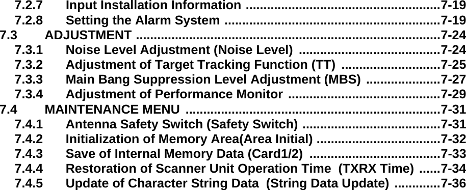
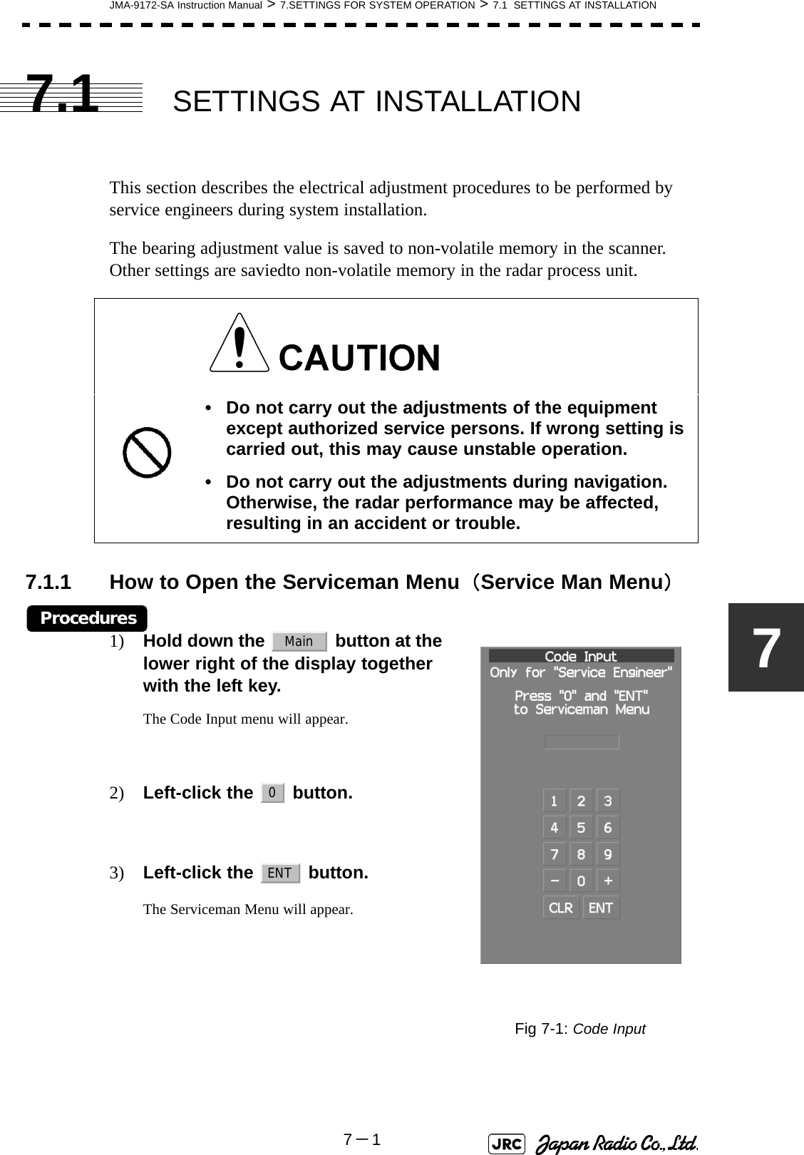
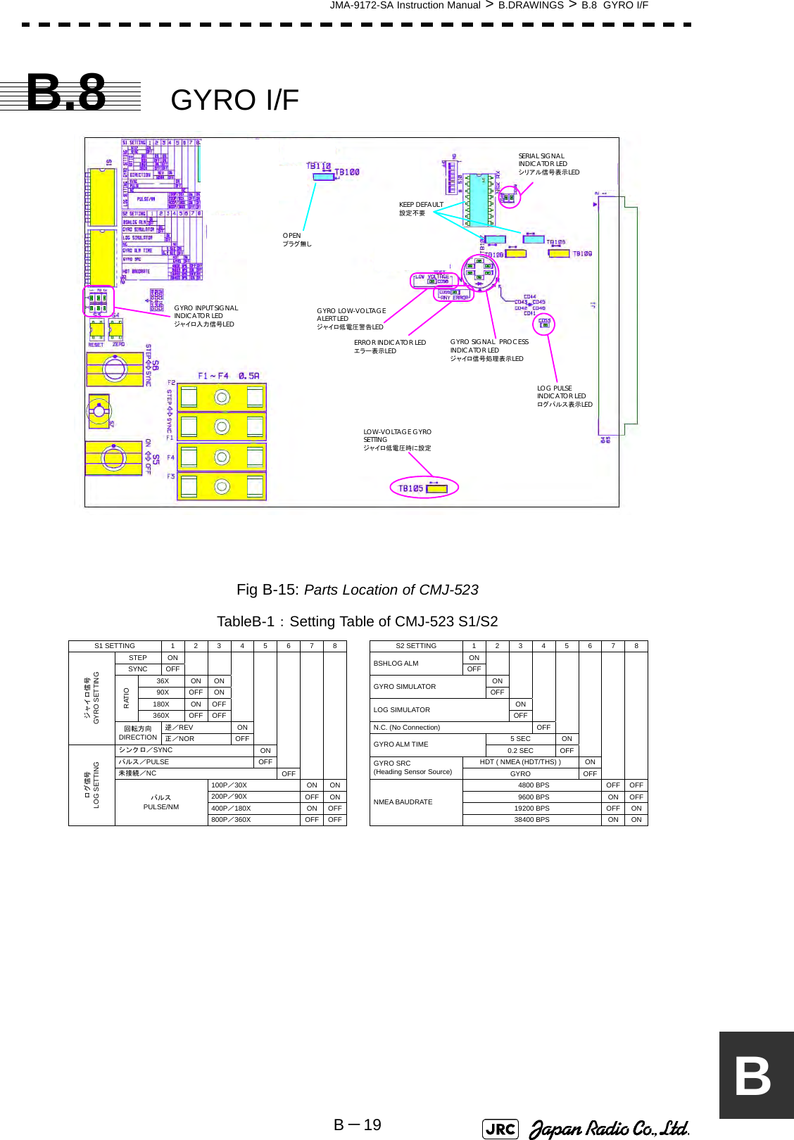
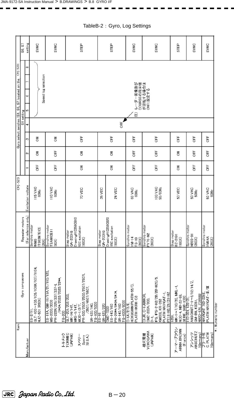
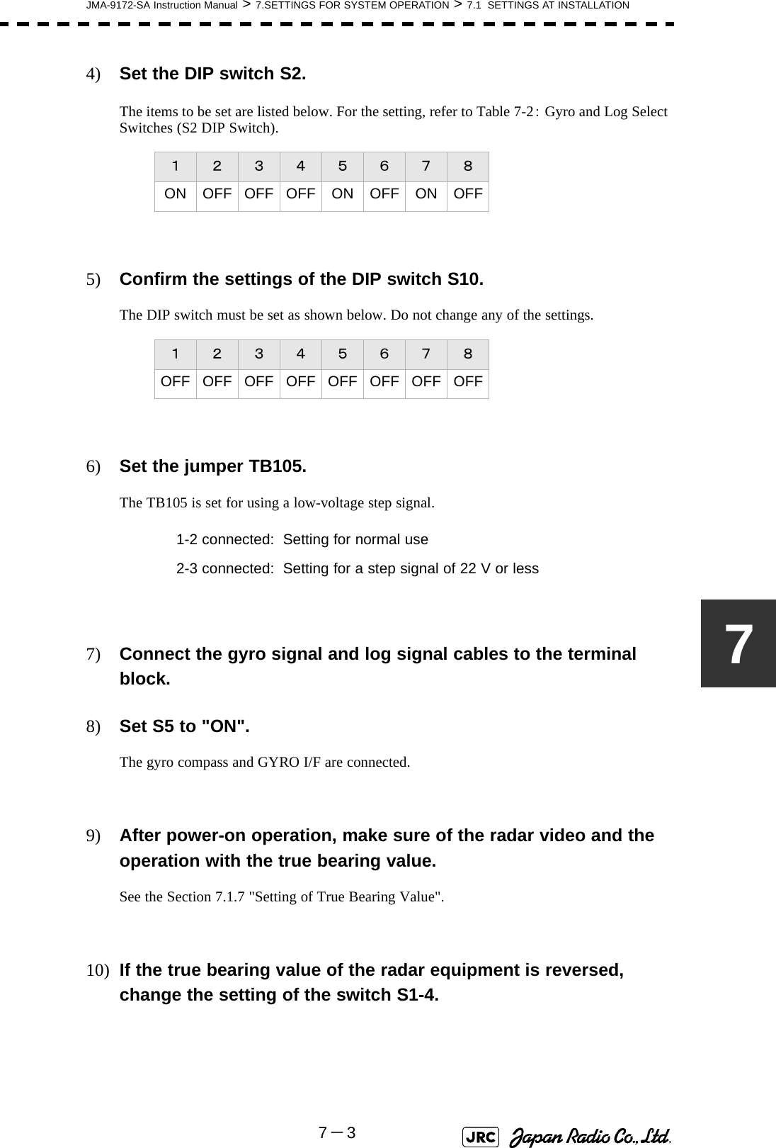
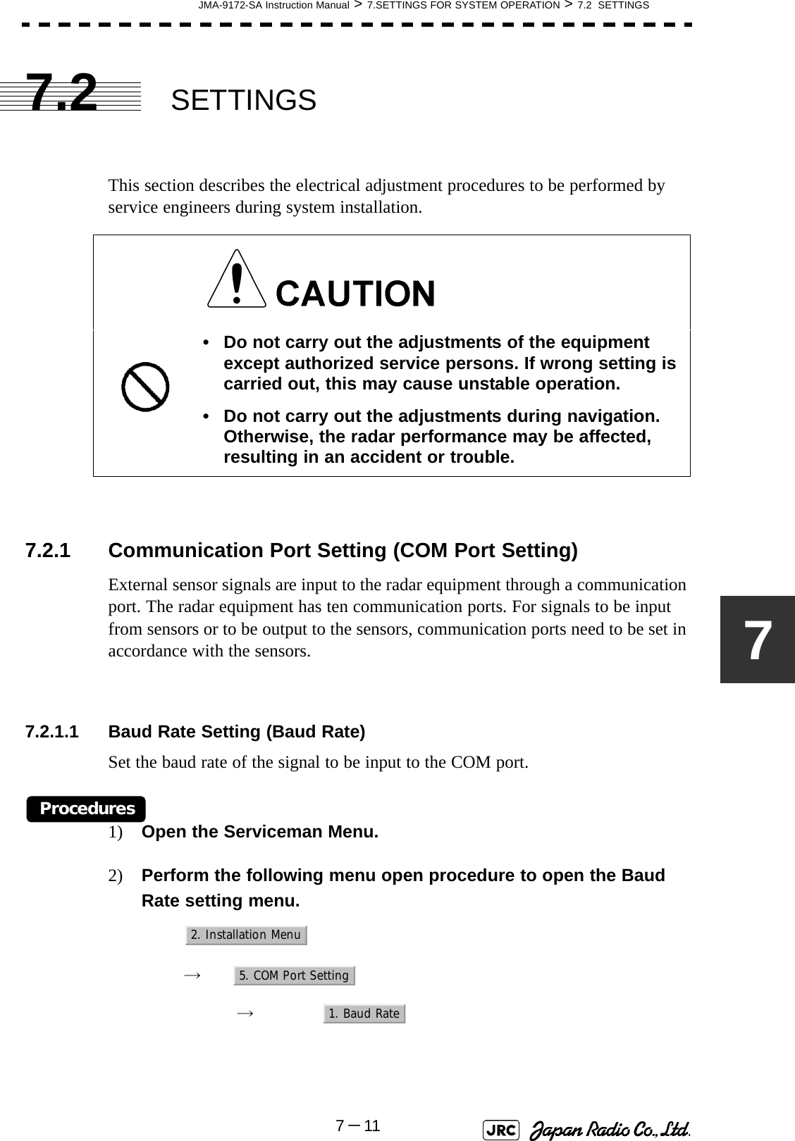
![7-2JMA-9172-SA Instruction Manual > 7.SETTINGS FOR SYSTEM OPERATION > 7.1 SETTINGS AT INSTALLATION7.1.2 GYRO I/F Settinga. Gyro Settings (STEP or SYNC)The GYRO I/F circuit of the system is designed to be compatible with most types of gyro compasses by simply setting the switches.Before power-on operation can be performed, the switches S1, S2, S5, S6, S7 and jumper TB105 on the gyro interface circuit (PC4201) must be set in accordance with the type of your gyro compass by performing the procedure below. The switches are factory-set for a gyration ratio of 180X and the step motor type. Make sure of the type of the gyro compass installed on the own ship before starting the procedure below.Procedures1) Set S5 to "OFF".The gyro compass and GYRO I/F are cut off.2) Set S6 and S7 in accordance with the type of your gyro compass.There are two types of gyro compasses: one type outputs a step signal, and the other type outputs a synchro signal. Make sure of the type of the gyro compass installed on the own ship before setting the switches S6 and S7.3) Set the DIP switch S1 in accordance with the type of the compass.The items to be set are listed below. For the settings, refer to Table 7-1: Gyro and Log Select Switches (S1 DIP Switch).Step motor type: DC24V to DC100VSynchro-motor type: Primary excitation voltage 50 to 115 VACSynchro signal: Set the switches to [SYNC].Step signal: Set the switches to [STEP].S1-1: Type of gyro signal (step/synchro)S1-2/3: Gyration ratio of gyro compassS1-4: Gyration direction of gyro compassS1-5: Type of log signal (pulse/synchro)S1-7/8: Ratio of log signal](https://usermanual.wiki/Japan-Radio/NKE1532.Users-Manual-2/User-Guide-1404444-Page-43.png)
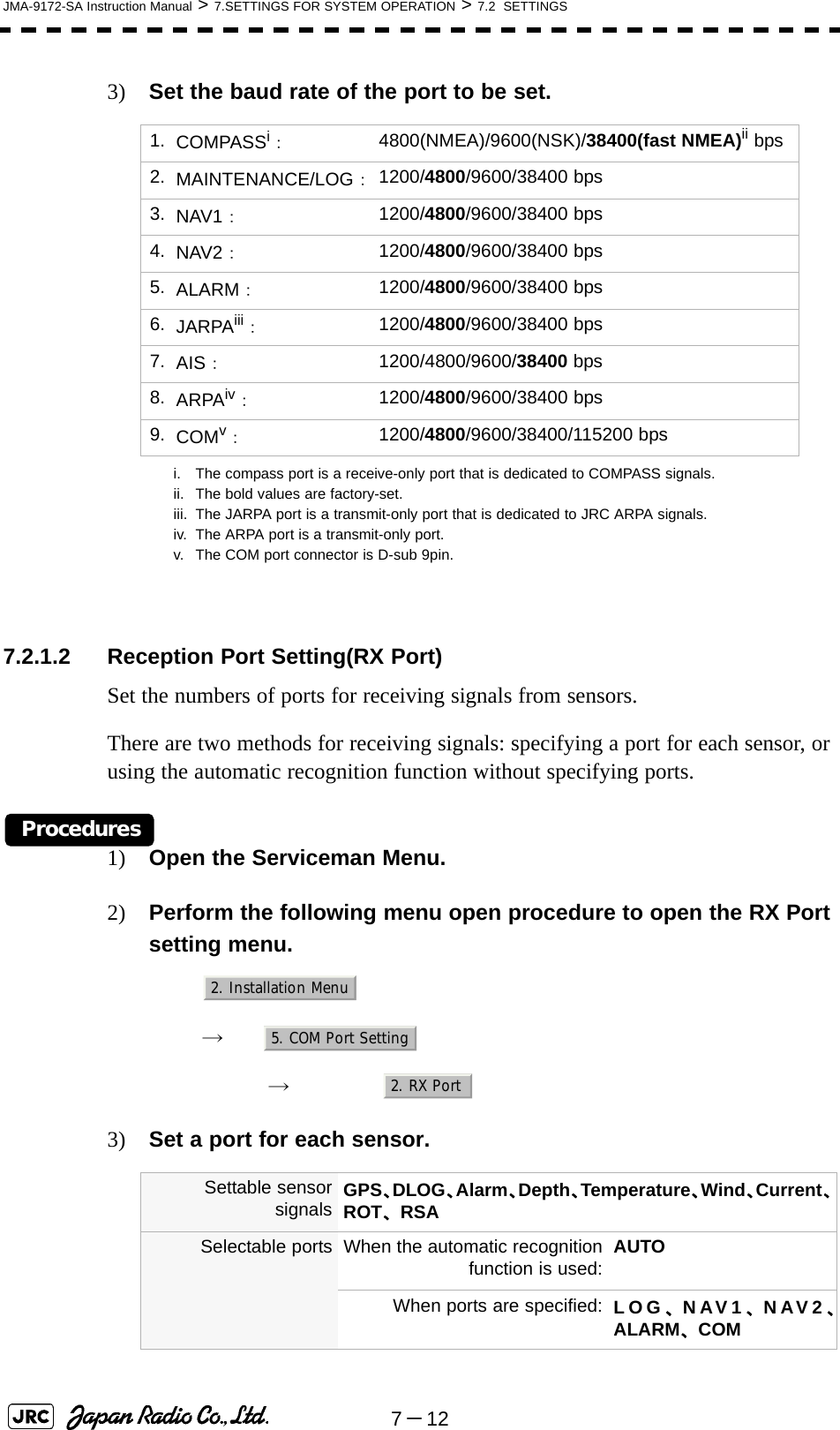
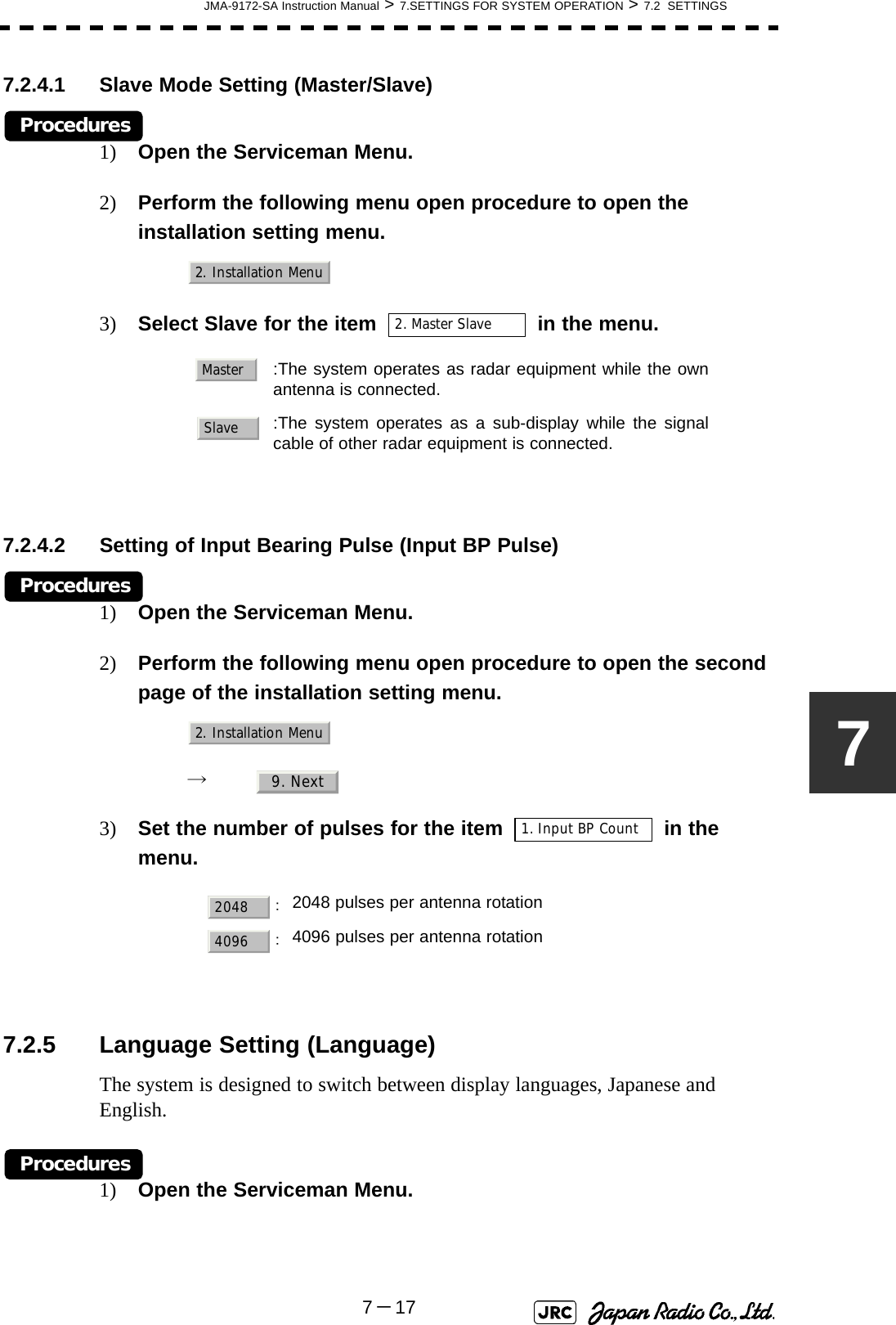
![7-16JMA-9172-SA Instruction Manual > 7.SETTINGS FOR SYSTEM OPERATION > 7.2 SETTINGS4) Set the starting azimuth of the sector blank by operating the [EBL] dial, and left-click the button. The start angle of the sector blank will be set.5) Set the ending azimuth of the sector blank by operating the [EBL] dial, and left-click the button.The end angle of the sector blank will be set.7.2.3 Setting of Bearing Pulses from Scanner Unit (Output Pulse)Set the output value of bearing pulses from the scanner unit. The system can set 2048 pulses or 4096 pulses. This setting is enabled only when the scanner unit of 25 or 30 kW is used.Procedures1) Open the Serviceman Menu.2) Perform the following menu open procedure to open the Output Pulse setting menu. → → 3) Set the number of pulses to be output by the scanner unit. 7.2.4 Slave Mode Setting (Master/Slave)Place the system in the Slave mode when it is to be operated as the sub-display that displays radar echoes by using radar signals from other radar equipment.The input value of externally input bearing pulses can be set. The system can set 2048 pulses or 4096 pulses.ii. If a 10 kW antenna is used, 2048 is always set.:2048 pulses per antenna rotation (Recommended value):4096 pulses per antenna rotationENTENT1. Adjust Menu4. TXRX Adjustment6. Output Pulse20484096](https://usermanual.wiki/Japan-Radio/NKE1532.Users-Manual-2/User-Guide-1404444-Page-57.png)
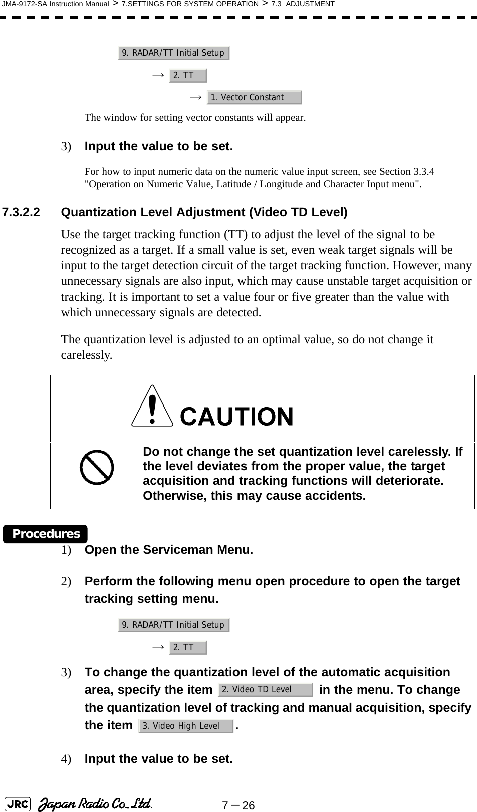
![JMA-9172-SA Instruction Manual > 7.SETTINGS FOR SYSTEM OPERATION > 7.3 ADJUSTMENT7-2777.3.3 Main Bang Suppression Level Adjustment (MBS)Main Bang Suppression is adjusted to suppress main bang, a reflection signal from 3D circuit including wave guide tube, that generally appears as a circular image focusing on the center of the radar display. Optimum adjustment allows main bang image to remain lightly on the display.7.3.3.1 Adjustment of Main Bang Suppression Level (MBS Level)Procedures1) Open the Serviceman Menu.2) Perform the following menu open procedure to open the MBS level adjustment menu.→ → 3) Set the radar as follows:•Set the radar range to 0.125 NM.•Set the radar video enhance function (ENH) to OFF.•Set the image processing (PROC) to OFF.•Turn the [RAIN] control to the minimum position (fully to the left).•Turn the [GAIN] control to the maximum position (fully to the right).•Turn the [SEA] control to achieve the strength with which main bang can be judged.4) Adjust the value so that the main bang can be erased. Do not change this adjusted level carelessly.Incorrect adjustment may erase targets in point-blank range and cause collision, resulting in death or serious injury.9. RADAR/TT Initial Setup3. MBS1. MBS Level](https://usermanual.wiki/Japan-Radio/NKE1532.Users-Manual-2/User-Guide-1404444-Page-68.png)
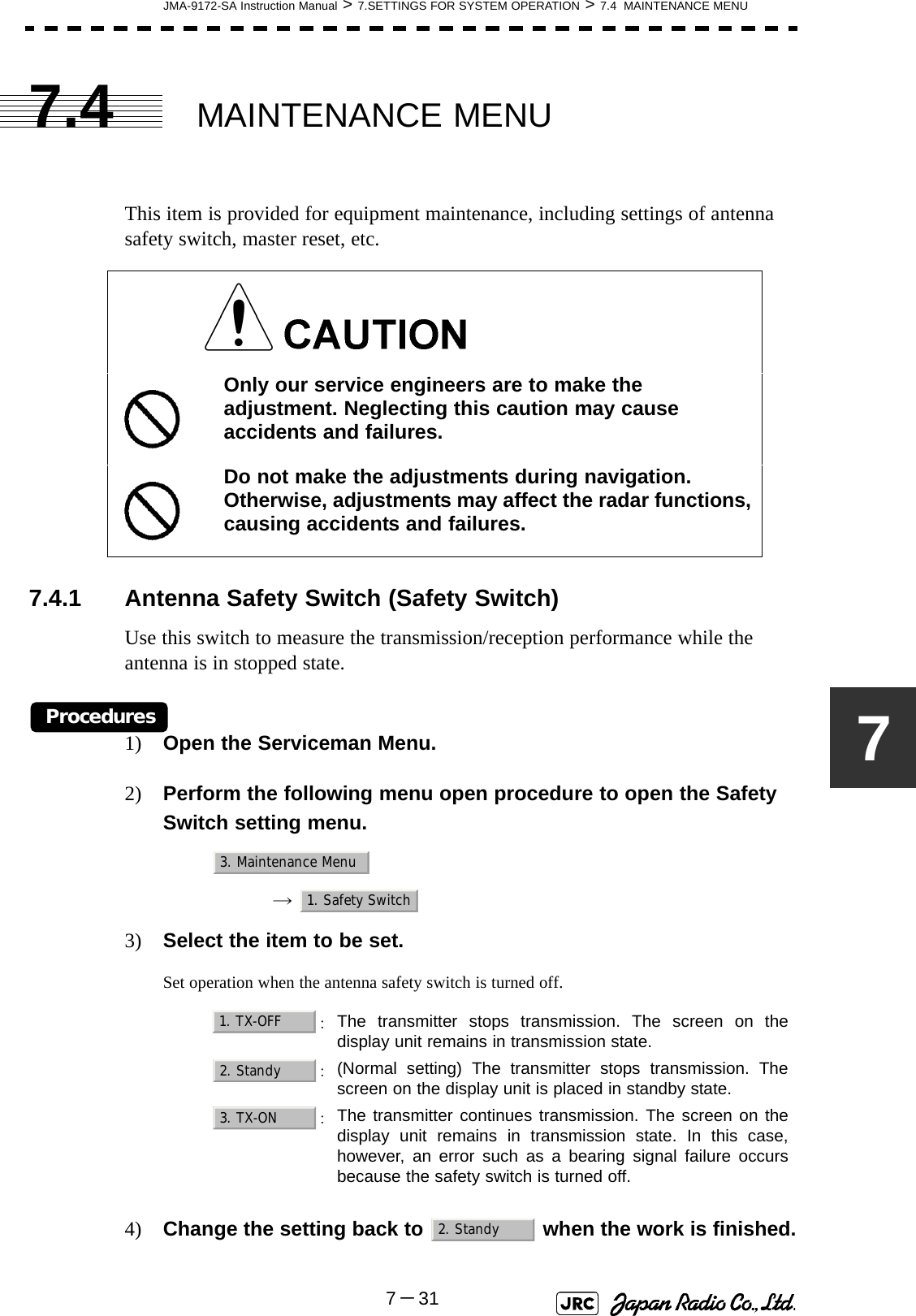
![7-28JMA-9172-SA Instruction Manual > 7.SETTINGS FOR SYSTEM OPERATION > 7.3 ADJUSTMENT7.3.3.2 Adjustment of Main Bang Suppression Area (MBS Area)Procedures1) Open the Serviceman Menu.2) Perform the following menu open procedure to open the MBS Area adjustment menu.→ → 3) Set the radar as follows:•Set the radar range to 0.125 NM.•Set the radar video enhance function (ENH) to OFF.•Set the image processing (PROC) to OFF.•Turn the [RAIN] control to the minimum position (fully to the left).•Turn the [GAIN] control to the maximum position (fully to the right).•Turn the [SEA] control to achieve the strength with which main bang can be judged.4) Adjust the value so that the main bang can be erased.9. RADAR/TT Initial Setup3. MBS2. MBS Area](https://usermanual.wiki/Japan-Radio/NKE1532.Users-Manual-2/User-Guide-1404444-Page-69.png)
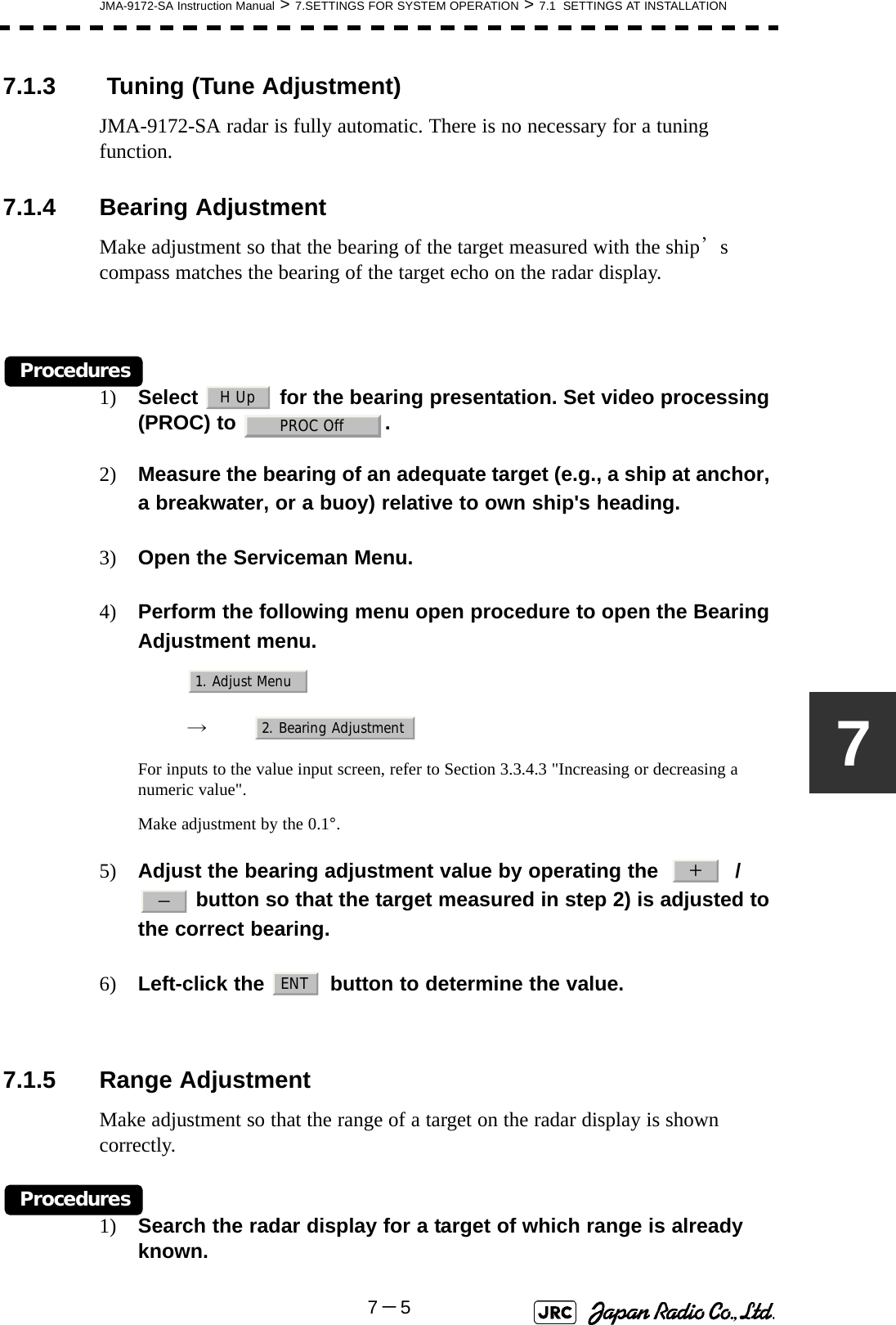
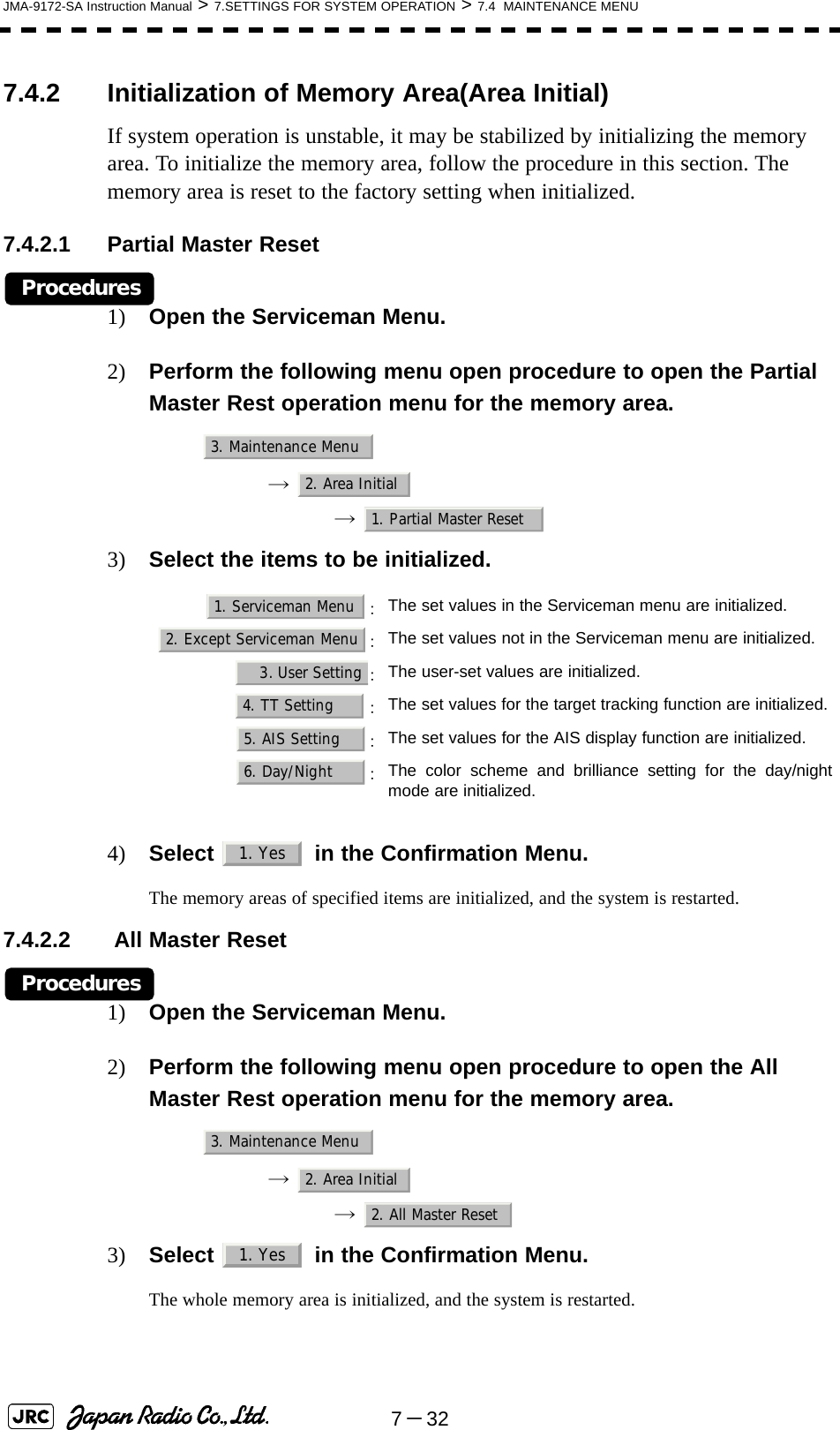
![JMA-9172-SA Instruction Manual > 7.SETTINGS FOR SYSTEM OPERATION > 7.3 ADJUSTMENT7-2977.3.4 Adjustment of Performance Monitor (SSR MON)AttensionReplace the Antenna unit, TRX Module(CMN-750), performance monitor circuit (CAY-71), and radar process circuits (CHA-396, CDC-1349, CMH-2246), adjust the perfomance monitor according to the procedures in this section:[i] Transmission Monitor Adjustment (Tx MON Adjustment)Procedures1) Set the master display unit for radar with the inter-switch function. (Interswitch is un-available for evaluation model.)2) Open the Serviceman Menu.3) Perform the following menu open procedure to open the “Tx Monitor Adjustment” menu. 1.Adjust Menu →4.TXRX Adjustment →7.SSR MON Setting →2. Tx MON Adjustment4) Adjust the “Tx MON Adjustment” value to “0.0 ± 1.0dB” by operating the “+” / “-” button.5) Left-click the “ENT” button.Adjust to “0.0±1.0dB”435](https://usermanual.wiki/Japan-Radio/NKE1532.Users-Manual-2/User-Guide-1404444-Page-70.png)
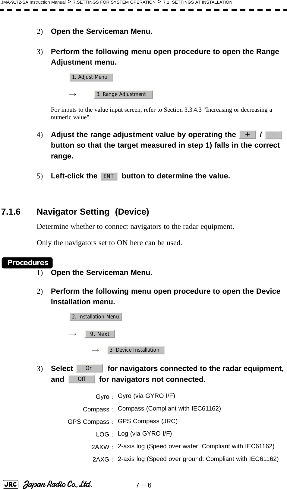
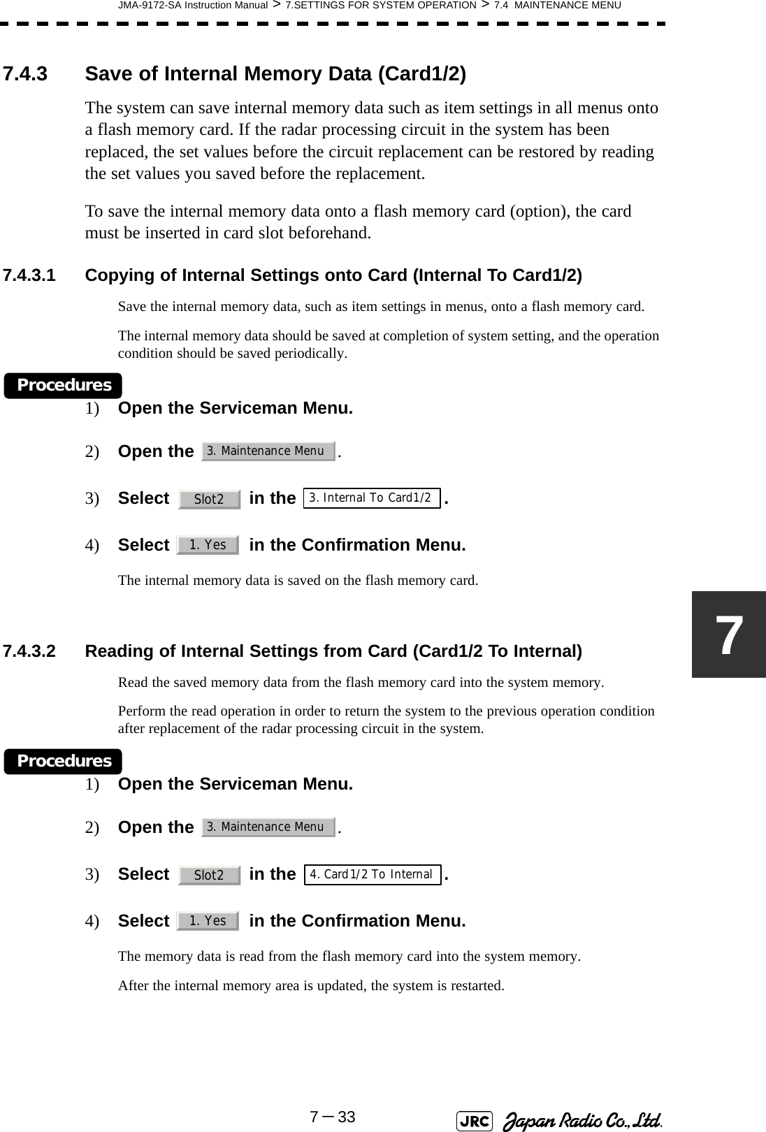
![7-30JMA-9172-SA Instruction Manual > 7.SETTINGS FOR SYSTEM OPERATION > 7.3 ADJUSTMENT[ii] Receiver Monitor Adjustment (Rx MON Adjustment)Attension Do not change the parameters of “6. Monitor Range” and “7.Rx MON Gain”.Procedures1) Set the master display unit for radar with the inter-switch function. (Interswitch is un-available for evaluation model.)2) Open the Serviceman Menu.3) Perform the following menu open procedure to open the “Tx Monitor Adjustment” menu. 1.Adjust Menu →4.TXRX Adjustment →7.SSR MON Setting →5. Monitor Sector4) The +/- button is operated so that "Rx ATT Value" may become the maximum. *The PM Rx area(22.5°) displayed on the PPI screen moves to operate "+/-" button. 5) Perform the following menu open procedure to open the “Rx MON Adjustment” menu.6) Adjust the “Rx MON Adjustment” value to “0.0 ± 1.0dB” by operating the “+” / “-” button.7) Left-click the “ENT” button. Maximum Adjust to “0.0dB±1.0dB”5.3. 6.7 5. 4.](https://usermanual.wiki/Japan-Radio/NKE1532.Users-Manual-2/User-Guide-1404444-Page-71.png)
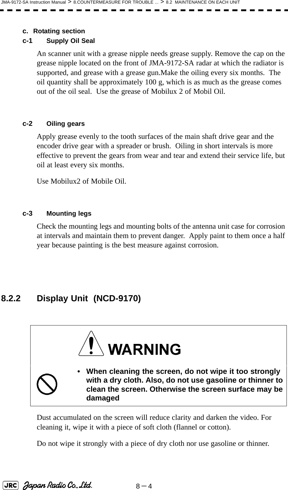
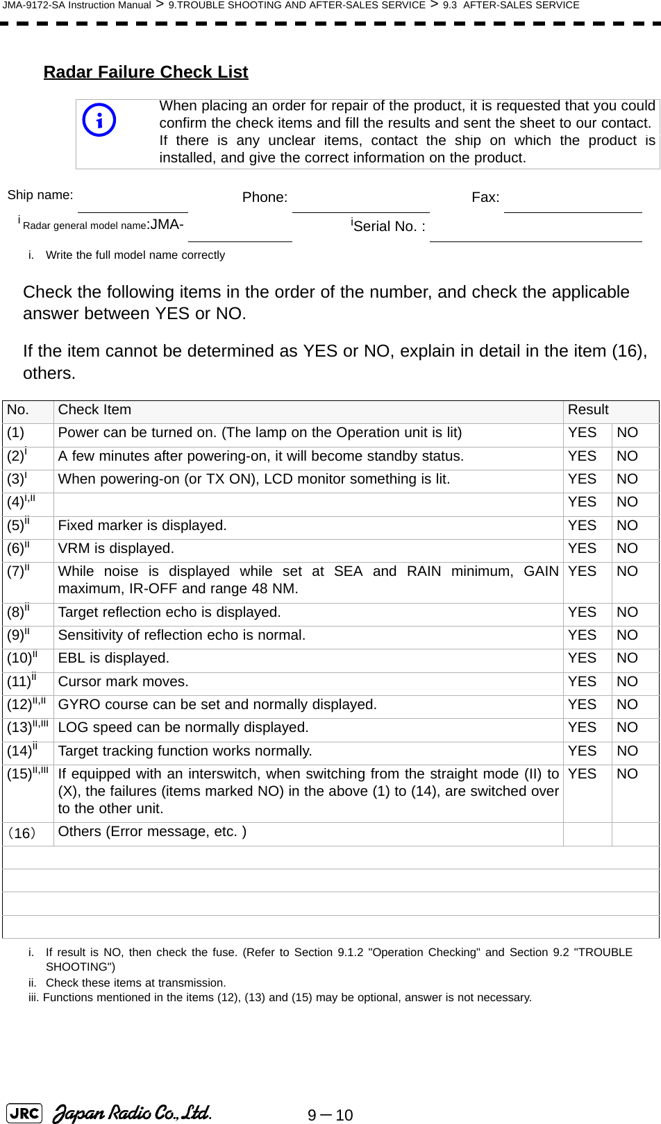
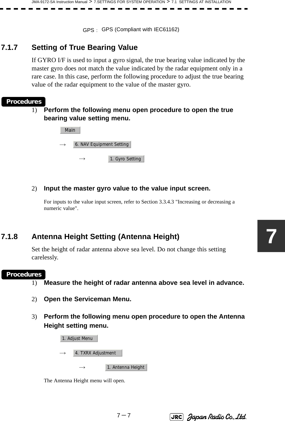
![JMA-9172-SA Instruction Manual > 8.COUNTERMEASURE FOR TROUBLE ... > 8.3 PERFORMANCE CHECK8-588.3 PERFORMANCE CHECKMake operational check on the radar equipment regularly and if any problem is found, investigate it immediately. Pay special attention to the high voltage sections in checking and take full care that no trouble is caused by any error or carelessness in measurement. Take note of the results of checking, which can be used effectively in the next check work.Operational check shall be made in accordance with Table 8-1 Function Check List in the order as specified in it.8.3.1 Check Performance on Test MenuThe radar operating state can be checked by opening the Test Menu.Table8-1: Performance Check ListEquipment Item to be checked Criteria RemarksDisplay Unit Video and echoes on the screen SensitivityLCD brilliance can be controlled correctlyVarious markersVarious numerical indicationsLightingCan be correctly controlledMemory See the Section [1] "Memory Test"Communications Lines See the Section [3] "Check ofCommunication Lines (Line Test)"Power Supply, Backup Battery See the Section [4] "Supply Voltage" Monitor See the Section 8.3.1.2 "Monitor Test"Operation Unit See the Section 8.3.1.3 "Operation UnitTest (Keyboard Test)" System Alarm Log Display See the Section 8.3.1.5 "System AlarmLog display" System Information Display See the Section 8.3.1.6 "SystemInformation" Target Tracking See the Section 5.2.7 "Operation Test(TT Test Menu)" Scanner Unit Signals from the Scanner Unit See the Section [2] "TXRX Test"Performance Monitor See the Section 8.3.1.4 "Check of thePerformance Monitor (MON Display)"](https://usermanual.wiki/Japan-Radio/NKE1532.Users-Manual-2/User-Guide-1404444-Page-84.png)
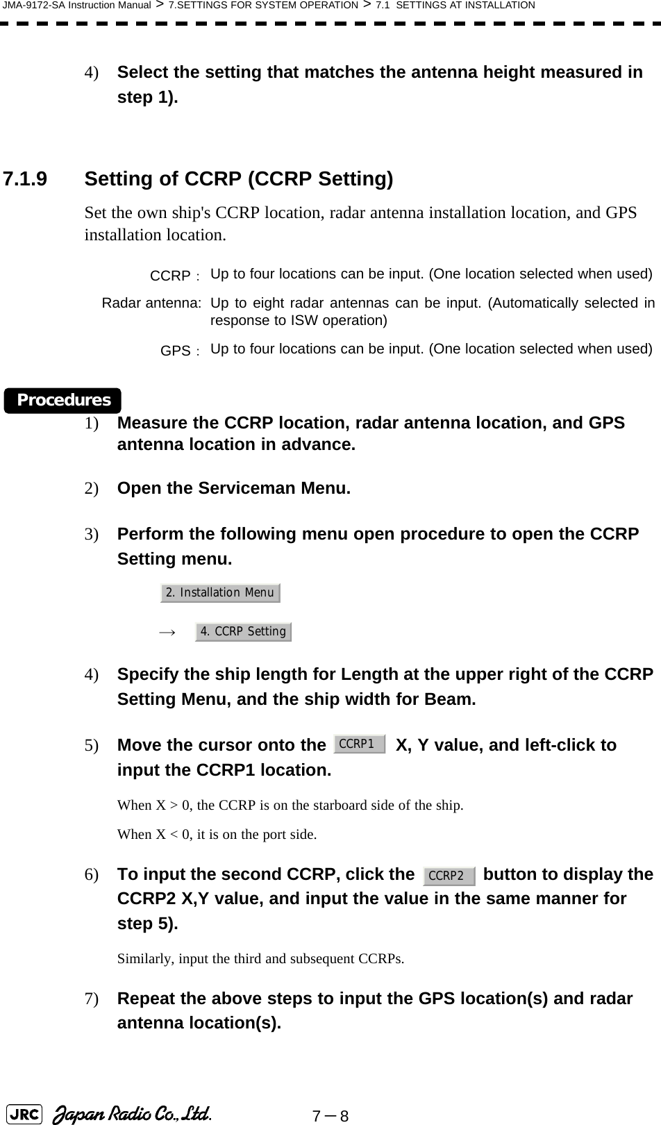
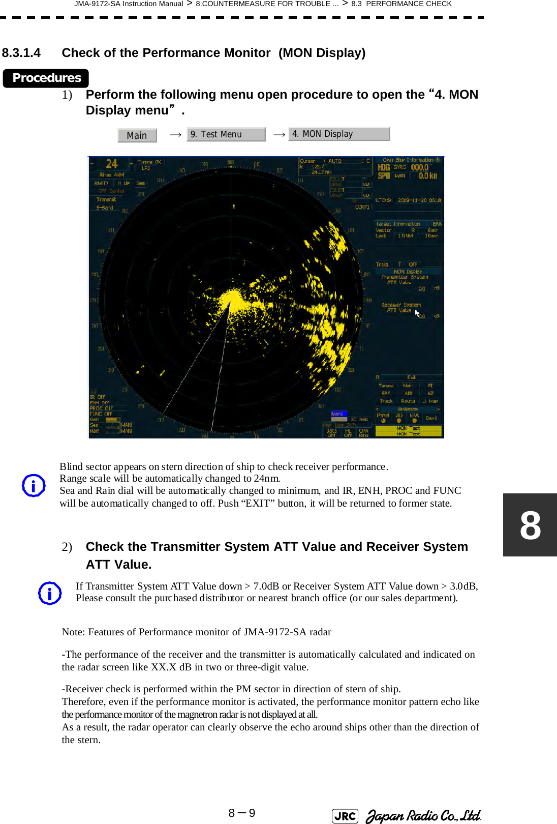
![8-6JMA-9172-SA Instruction Manual > 8.COUNTERMEASURE FOR TROUBLE ... > 8.3 PERFORMANCE CHECKProcedures1) Perform the following menu open procedure to open the Test Menu.→ 2) Select the items to be checked.The list of check items will appear.8.3.1.1 Self-diagnosis function (Self Test)Check of memory, scanner unit, and communications Lines[1] Memory TestChecks for the performance of built-in memory.When no abnormality is found, OK is displayed. When an abnormality is found, NG is displayed. [2] TXRX TestChecks for signals from the scanner.8.3.1.1Self-diagnosis function (Self Test)8.3.1.2Monitor Test8.3.1.3Operation Unit Test (Keyboard Test)8.3.1.4Check of the Performance Monitor (MON Display)8.3.1.5System Alarm Log display8.3.1.6System Information[1]Memory Test[2]TXRX Test[3]Check of Communication Lines (Line Test)[4]Supply VoltageSDRAM CheckSRAM CheckFLASH ROM CheckGRAPHIC CheckScanner's safety switch checkMain9. Test Menu1. Self Test2. Monitor Test3. Keyboard Test4. MON Display5. System Alarm Log6. System Information1. Memory Test2. TXRX Test3. Line Test4. Supply Voltage1. SDRAM2. SRAM3. FLASH ROM4. GRAPHICSafety Switch](https://usermanual.wiki/Japan-Radio/NKE1532.Users-Manual-2/User-Guide-1404444-Page-85.png)
![JMA-9172-SA Instruction Manual > 8.COUNTERMEASURE FOR TROUBLE ... > 8.3 PERFORMANCE CHECK8-78When no abnormality is found, OK is displayed. When an abnormality is found, NG is displayed.In standby, ** will appear.[3] Check of Communication Lines (Line Test)Check the status of communications with options.When no abnormality is found, OK is displayed. When an abnormality is found, NG is displayed.The status display field of equipment not connected is left blank.[4] Supply VoltageCheck the voltage of internal power supply. Scanner rotation signal checkHeading line signal checkCheck on the load current of high voltage inthe modulatorRadar trigger signal checkRadar video checkCheck on connection with the transmitter-receiverCheck on connection with the signal processing circuitCheck on connection with the target tracking unitCheck on connection with the GYRO I/F unitCheck on connection with the interswitchItem Normal operating range12V 11.4 to 12.6V5V 4.75 to 5.25V3.3V 3.14 to 3.46VBattery 2.5V or moreAZI PulseHL PulseMH CurrentTriggerVideoTXRXSIG. PROCTT GYRO I/F ISW](https://usermanual.wiki/Japan-Radio/NKE1532.Users-Manual-2/User-Guide-1404444-Page-86.png)
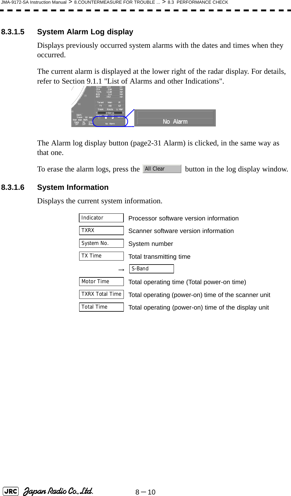
![8-8JMA-9172-SA Instruction Manual > 8.COUNTERMEASURE FOR TROUBLE ... > 8.3 PERFORMANCE CHECK8.3.1.2 Monitor TestChecks for the display.The test pattern will be shown on the display.To return to the normal display, press any key.If errors occur in the monitor, no test pattern will appear.8.3.1.3 Operation Unit Test (Keyboard Test)Checks for the controls and switches of the operation panel.[1] Key TestChecks for the controls and switches of the operation panel.Each key on the operation panel on the display is shown in reverse video at the same time the key is pressed, and the name of the pressed key is displayed.[2] Buzzer TestChecks for the operation panel buzzer.The buzzer will sound. The buzzer automatically stops after it sounds for a specified length of time.[3] Light TestChecks for the control panel light.The brightness of the operation panel is gradually intensified at four levels. :All colors are filled with white.:A white box is displayed on the black background of1280×1024dot.:Displays rectangle X 2, circle X 2, and cross-shape X13(white lines on the black background).:Displays “H” of 9 dots X 9 dots on the entire screen (whitecharacter on the black background).:Gray scale display (16 levels):Displays a color bar.:Displays the VDR test pattern.:Displays the specified color.[1]Key Test[2]Buzzer Test[3]Light Test1. Pattern12. Pattern23. Pattern34. Pattern45. Pattern56. Pattern67. Pattern78. Pattern81. Key Test2. Buzzer Test3. Light Test](https://usermanual.wiki/Japan-Radio/NKE1532.Users-Manual-2/User-Guide-1404444-Page-87.png)
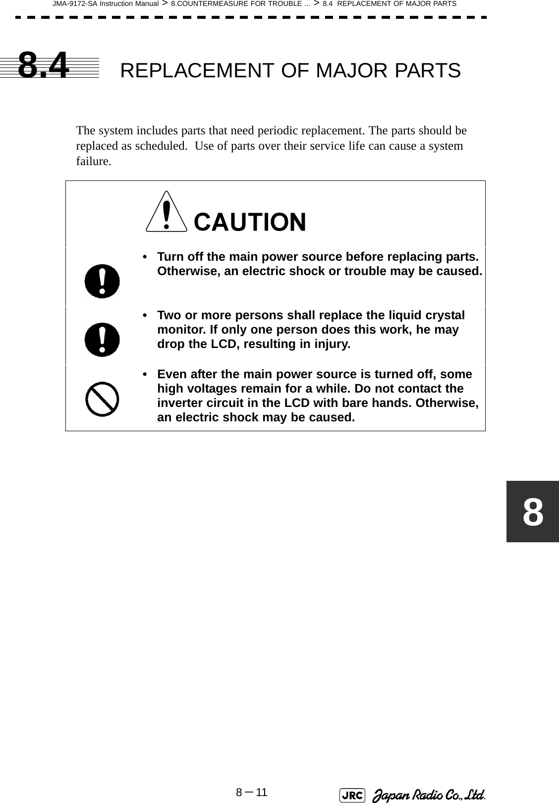
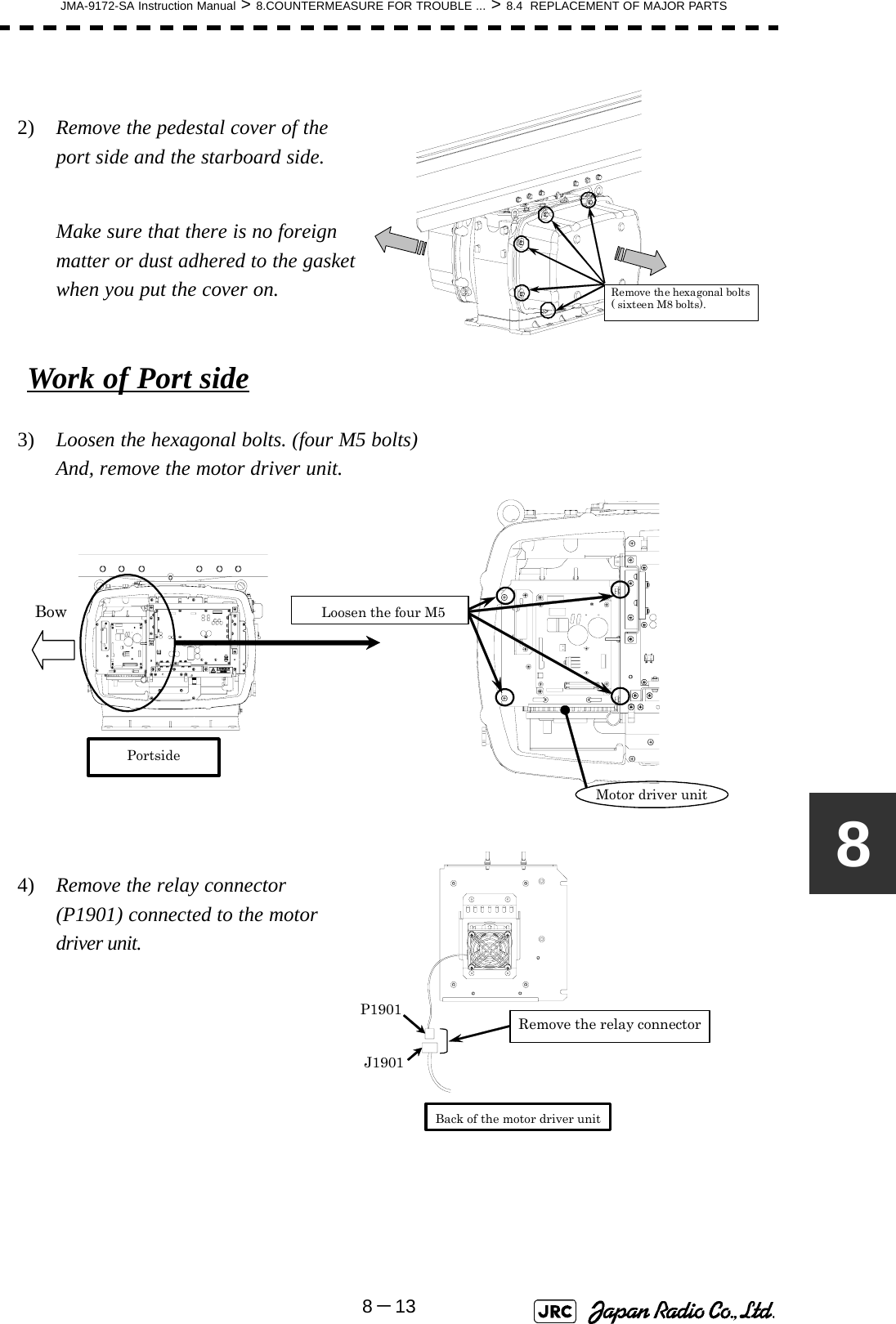
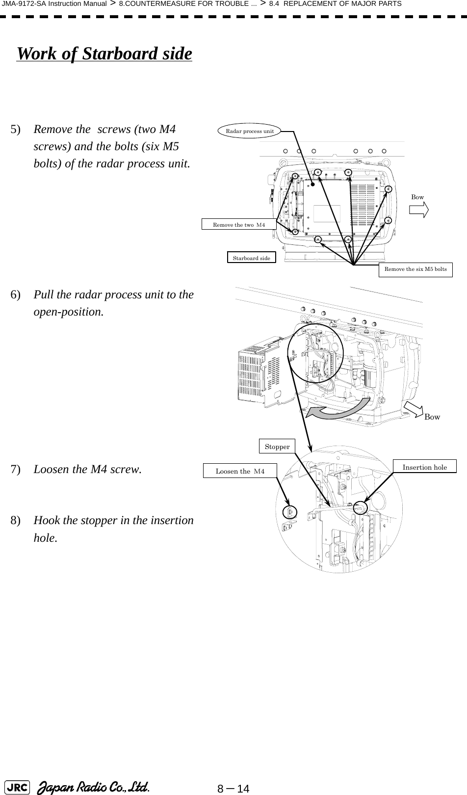
![8-12JMA-9172-SA Instruction Manual > 8.COUNTERMEASURE FOR TROUBLE ... > 8.4 REPLACEMENT OF MAJOR PARTS8.4.1 Parts Required for Periodic ReplacementHere are parts required for periodic replacement8.4.2 Replacement of Motor8.4.2.1 Scanner Unit NKE-1532[Required tools]•Wrenches (M5, M8, and M10)•A Phillips screwdriver (M2)[Required procedure]Removal of the pedestal cover1) Turn off the safety switch of the scanner before replacing the motor. Part name Interval Part type Part code1. Motor 10,000 hours MDBW10823*ii. “*” means revision, such as A, B and so on.ii. The φ92mm Fan is auxiliary use of the φ120mm Fan. MDBW10823*i2. Fan (Scanner Unit) φ120mm (Radar process Unit) φ92mm*ii (Radar process Unit) φ60mm (Motor Driver) φ60mm (Power Supply Unit)90,000 hours45,000 hours45,000 hours45,000 hoursH-7ZCRD1569*iH-7ZCRD1570*iH-7ZCRD1572*iH-7ZCRD1574*i7ZCRD1569*i7ZCRD1570*i7ZCRD1572*i7ZCRD1574*i3. LCD PANEL 50,000 hours 7WASR002*i7WASR002*i4. Fan (Display Unit)(Radar Process Circuit) 20,000 hours 109R0612S4D13 5BFAB00588(Power Supply) 20,000 hours H-7BFRD0006*i7BFRD0006*i5. Backup battery 5 years CR2032 5ZBCJ00012Replacement of motor must be made by specialized servicepersonnel. For details, refer to Service Manual. Turn off the safety switch.](https://usermanual.wiki/Japan-Radio/NKE1532.Users-Manual-2/User-Guide-1404444-Page-91.png)
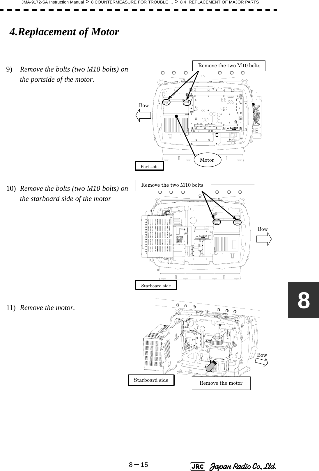
![8-16JMA-9172-SA Instruction Manual > 8.COUNTERMEASURE FOR TROUBLE ... > 8.4 REPLACEMENT OF MAJOR PARTS12) Grease the gear wheel of the new motor.13) Install the new motor in the scanner unit and secure it using the hexagonal bolts. Tighten the bolts with the specified torque (380 kgf-cm).14) After replacing the motor, and assemble the unit in the reverse order of the disassembly procedure.Do not forget to tighten the screws and bolts .Do not forget to connect the cables.[Operation check]Follow the procedure below to check the operation after you have replaced the motor.1) Turn on the radar power supply. When the Countdown is completed, push the “TX / STBY” button and check that the radar image appears without error. Check that you do not listen any unusual sound starting, rotating, and stopping the motor.2) Open the service engineer menu, and initialize the motor rotation time. Grease the motor gear wheel](https://usermanual.wiki/Japan-Radio/NKE1532.Users-Manual-2/User-Guide-1404444-Page-95.png)
![JMA-9172-SA Instruction Manual > 8.COUNTERMEASURE FOR TROUBLE ... > 8.4 REPLACEMENT OF MAJOR PARTS8-1788.4.3 Replacement of 23inch LCD Do not touch the LCD screen directly with your fingers.Do not touch the AR filter directly with your fingers.Perform the replacement work on a soft cloth to avoid damage to the LCD screen and other parts.[Required tools]•A Phillips screwdriver for 4 mm screws•A Phillips screwdriver for 6 mm screws[Disassembly]1) Remove the tilt fixing handle (standalone type only).2) Tilt up the screen as much as you can (standalone type only).3) Remove the screws (M6) from the four corners and displace the face cover.Replacement of LCD monitor must be made by specializedservice personnel. For details, refer to Service Manual.Remove](https://usermanual.wiki/Japan-Radio/NKE1532.Users-Manual-2/User-Guide-1404444-Page-96.png)
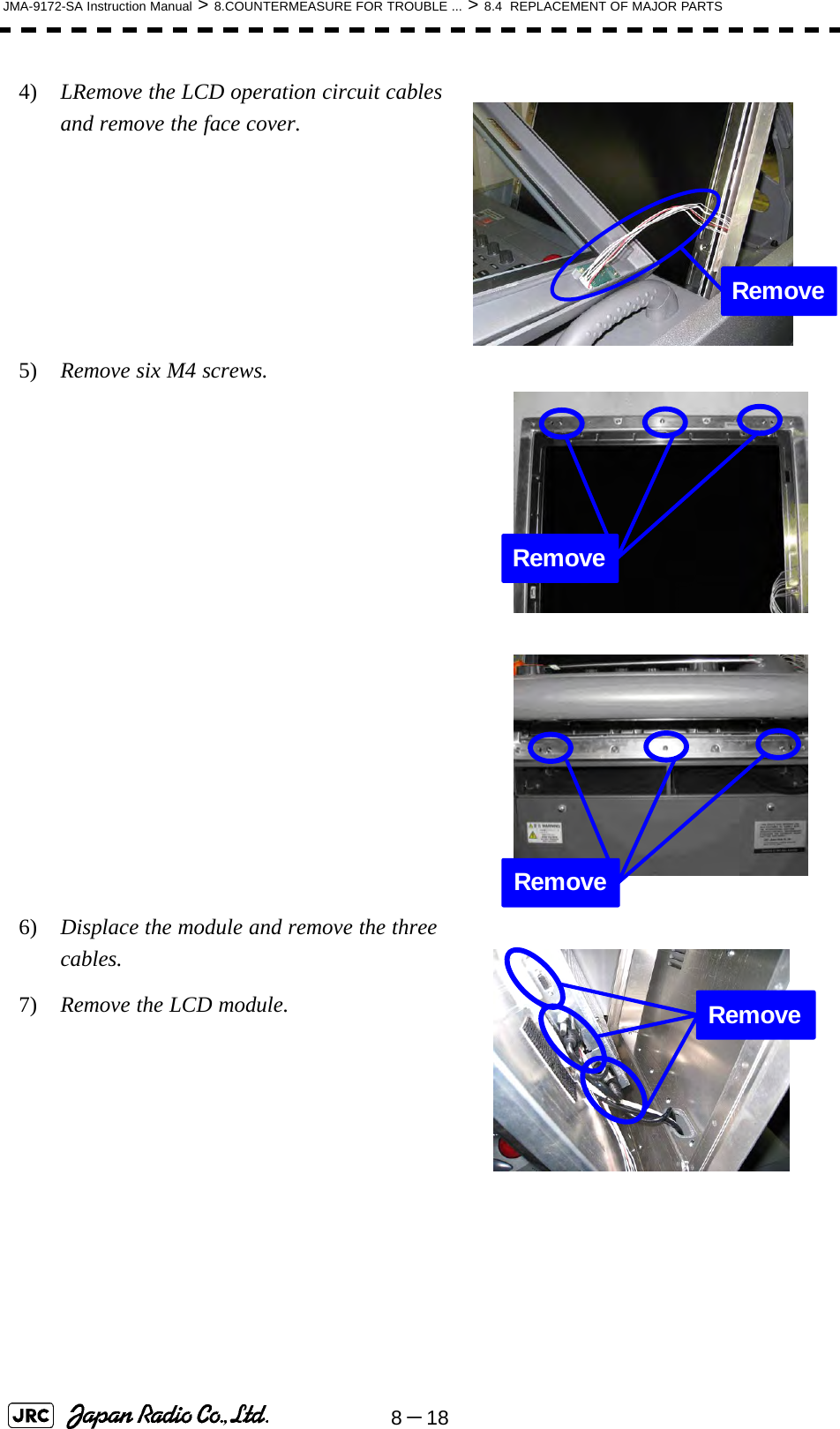
![JMA-9172-SA Instruction Manual > 8.COUNTERMEASURE FOR TROUBLE ... > 8.4 REPLACEMENT OF MAJOR PARTS8-198[Assembly]1) Tighten the lower three M4 screws halfway.2) Connect the cables to the LCD module.3) Align the module to the lower three screws and insert it downward.4) Check the positions of the two bosses and ensure that appropriate space is maintained under the LCD module. Tighten the six screws evenly.5) Connect the LCD operation circuit cables and attach the face cover.6) Tighten the screws at the four corners.7) Attach the tilt fixing handle.[Operation Check]1) After completing the replacement procedures, start the system to make sure that images are displayed properly.2) Turn the brightness knob to make sure the brightness can be changed between the minimum and the maximum levels. Temporary tightening Positions of the two bosses](https://usermanual.wiki/Japan-Radio/NKE1532.Users-Manual-2/User-Guide-1404444-Page-98.png)
![8-20JMA-9172-SA Instruction Manual > 8.COUNTERMEASURE FOR TROUBLE ... > 8.4 REPLACEMENT OF MAJOR PARTS8.4.4 Replacement of Backup BatteryA coin-cell battery maintains radar system configuration, date, and time information while power off condition. Radar system configuration is saving to non-volatile memory at fixed intervals.8.4.4.1 About the Battery AlarmIf is appeared at the lower-right of the display when start up the radar system, the battery has not enough time left to live. We recommend to replace the battery.If is appeared at the lower-right of the display when start up the radar system, the battery has no time left to live. There is a necessary to replace the battery. In This condition, this radar system is restored configuration information from flash memory and normal operation is available. However, you turned of the radar system before saving to flash memory, the configuration information is maybe lost. In this case, you must setup the configuration again.8.4.4.2 How to Replacement of Backup Battery[Required tools]•A flat tip screwdriver for 6 mm screws•A Phillips screwdriver for 4 mm screws•A flat tip nonconductive screwdriver for 3 mm screwsReplacement of backup battery must be made by specializedservice personnel. For details, refer to Service Manual.About disposal of used battery, refer to Section 10.2.Battery LowBattery Dead](https://usermanual.wiki/Japan-Radio/NKE1532.Users-Manual-2/User-Guide-1404444-Page-99.png)
![JMA-9172-SA Instruction Manual > 8.COUNTERMEASURE FOR TROUBLE ... > 8.4 REPLACEMENT OF MAJOR PARTS8-218[Disassembly]1) Remove the four fixing screws to remove the cover from the display unit (NCD-9170).(A flat tip screwdriver for 6 mm screws)For standalone type NCD-9170For desktop type: NDC-14782) Remove the cable connected to the radar process circuit board.The radar process circuit is the first board from the left.3) Remove the two fixing screws (M4).4) Pull out the board to the front.5) Insert the flat tip nonconductive screwdriver for adjustment or some stick between the battery and the battery holder and lift the battery up.RemoveRemoveRemove](https://usermanual.wiki/Japan-Radio/NKE1532.Users-Manual-2/User-Guide-1404444-Page-100.png)
![8-22JMA-9172-SA Instruction Manual > 8.COUNTERMEASURE FOR TROUBLE ... > 8.4 REPLACEMENT OF MAJOR PARTS6) Insert the flat tip nonconductive screwdriver for adjustment or some stick to the location shown in the figure below and slide the battery sideways to remove the battery. [Assembly]1) Check the polarity of the battery. Make sure that the battery's positive (+) side is facing up.2) Slide the battery sideways into the battery holder.3) Make sure that the battery is inserted fully.[Check Item]1) Check that no error message comes up.2) Check that the system starts up normally.[Notes]](https://usermanual.wiki/Japan-Radio/NKE1532.Users-Manual-2/User-Guide-1404444-Page-101.png)