Japan Radio NKE1532 MARINE RADAR User Manual JMA 9100 series RADAR Instruction Manual
Japan Radio Co Ltd. MARINE RADAR JMA 9100 series RADAR Instruction Manual
Contents
- 1. Users Manual 1
- 2. Users Manual 2
Users Manual 2
5-34
JMA-9172-SA Instruction Manual > 5.OPERATION OF TARGET TRACKING AND AIS > 5.3 AIS OPERATION
4) Set an ending bearing and range by turning the [EBL] dial and
[VRM] dial, and left-click.
5.3.7.4 AIS Filter Display On/Off (Filter Display)
Procedures
1) Open the AIS Filter Setting menu by performing the following
menu operation.
→
2) Left-click the item button of .
Filter Display will be set to on or off.
5.3.7.5 Display of Targets outside AIS Filter (Filter Mode)
Procedures
1) Open the Filter Mode menu by performing the following menu
operation.
→
2) Left-click the item button of .
i
When the automatic activation function is enabled, the filter
range is automatically changed for covering the automatic
activation zone. Thus, the automatic activation zone is always
within the filter range.
: Displays only AIS targets in the AIS filter.
: Displays AIS targets in the AIS filter by priority, and also
displays targets outside the AIS filter.
iActivated AIS targets can be displayed even when they are
outside the AIS filter.
AIS
4. AIS Filter Setting
3. Filter Display
AIS
4. AIS Filter Setting
6. Filter Mode
Display
Priority
JMA-9172-SA Instruction Manual > 5.OPERATION OF TARGET TRACKING AND AIS > 5.3 AIS OPERATION
5-35
5
5.3.7.6 Point Filter
AIS targets which are not displayed because they are outside the AIS filter or at
low priority levels can be activated by giving a higher priority to them.
Procedures
1) Put the cursor on the position where a point filter is to be set,
and right-click to select the filter to be set.
2) The setting items for cursor modes will be displayed.Left-click .
A point filter will be set at the cursor position.
If an AIS target is in the point filter, it will be activated.
When an AIS target is activated or an AIS target is not found within one minute, the point
filter will be cleared.
5.3.8 Conditions for Deciding AIS Target to be Lost
About a lost target
When the data of an AIS target cannot be received for a specified time, the target
is decided to be lost and the target data is deleted. As shown in the table below,
the time until target data is deleted varies depending on the class of receive data
and the target status.
If the [ALARM ACK] key is pressed, the symbol is cleared.
i
The point filter's range is 1 nm, and cannot be changed.
Deciding AIS Target to be Lost
Target status Time until data deletion
SOLAS ship (Class A) SOLAS ship (Class B)
Vessel below 3 knots (Class A) or 2 knots
(Class B) and it is now at anchor or on the berth 18 min 18 min
Vessel of 3 knots or more and it is now at
anchor or on the berth 60 sec 18 min
Vessel of 0 to 14 knots (Class B: 0 to 14 knots) 60 sec 180 sec
Vessel of 14 to 23 knots 36 sec 180 sec
Vessel of 23 knots or more 30 sec 180 sec
SAR (Search and Rescue) 60 sec 60 sec
ATON (Aid to Navigation) 18 min 18 min
Base Station 60 sec 60 sec
iWhen a dangerous target ship is lost, a lost alarm is issued and the symbol
changes to a lost symbol. The lost symbol will display continuously on the
last-received position.
2. ACT AIS
5-36
JMA-9172-SA Instruction Manual > 5.OPERATION OF TARGET TRACKING AND AIS > 5.3 AIS OPERATION
5.3.9 Setting Conditions for AIS Alarm (AIS Alarm Setting)
Conditions for issuing a Lost alarm and CPA/TCPA alarm for AIS targets can be
set.
5.3.9.1 Setting of Condition for Lost Alarm
Procedures
1) Open the AIS Alarm Setting menu by performing the following
menu operation.
→
2) Left-click the item button of .
The setting items for Lost Alarm will be displayed.
3) Left-click the item button corresponding to the condition to be
set.
5.3.9.2 Setting of Condition for CPA/TCPA Alarm
Procedures
1) Open the AIS Alarm Setting menu by performing the following
menu operation.
→
2) Left-click the item button of .
The setting items for CPA/TCPA Alarm is switched.
: A lost alarm is not issued.i
i. A lost alarm is not issued for sleeping AIS targets.
: A lost alarm is issued only for AIS targets for which a dangerous
target alarm has been issued.
: A lost alarm is issued only for activated AIS targets and AIS
targets for which a dangerous target alarm has been issued.
: A lost alarm is issued only for activated AIS targets, data
indicated AIS targets and AIS targets for which a dangerous
target alarm has been issued.
: A CPA/TCPA alarm is not issued.i
i. When the Lost Alarm menu set to Off, the CPA ring color changes to dark color.
: A CPA/TCPA alarm is issued only for activated AIS targets.
: A CPA/TCPA alarm is issued for all AIS targets on the radar
display.
AIS
6. AIS Alarm Setting
1. Lost Alarm
Off
Danger
ACT&Danger
ACT&Danger&Select
AIS
6. AIS Alarm Setting
CPA/TCPA Alarm
Off
ACT
ACT&Sleep
JMA-9172-SA Instruction Manual > 5.OPERATION OF TARGET TRACKING AND AIS > 5.4 DECISION OF TARGETS AS IDENTICAL
(Association)
5-37
5
5.4 DECISION OF TARGETS AS
IDENTICAL (Association)
5.4.1 Setting of Function to Decide Targets as Identical
(Association)
When an AIS target and a tracking target are decided to be identical, an
association symbol is displayed for the targets regarded as identical. In this case,
the AIS target symbol is automatically activated.
Procedures
1) Left-click the in Target Information located at the
upper right of the display.
Association will be set to on or off.
5.4.2 Setting of Conditions for Deciding AIS and Tracked Targets
as Identical (Association Setting)
Procedures
1) Open the Association Setting menu by performing the following
menu operation.
→
The Association Setting menu will appear.
2) Select and enter the item to be set.
Conditions for deciding targets as identical will be set. When the differences of all item
between AIS and tracked target are under the set conditions..
• Turn off in order not to make a decision
on if targets are identical, or in order to display
symbols that have disappeared.
Attention
Association
Association
AIS
1. Association Setting
5-38
JMA-9172-SA Instruction Manual > 5.OPERATION OF TARGET TRACKING AND AIS > 5.4 DECISION OF TARGETS AS IDENTICAL
(Association)
Once regard as identical, when one of the differences exceed 125% of the set condition, they
are regarded as dissidence.
5.4.3 Types of Decision Conditions to be Set
iThe setting for this function is common to Association Setting in
the AIS Menu.
Decision conditions
1. Association On / Off (Function to decide targets as
identical)
2. Priority AIS / TT (Symbol to be displayed)
3. Bearing 0.0~9.9°
4. Range 0~999m
5. Cource 0~99°
6. Speed 0~99kn
7.Applicable AIS Target ACT or ACT&Sleep (activated AIS target or
all AIS target)
If a great value is set as a condition for deciding
targets as identical, a tracking target near an AIS target
is regarded as identical to the AIS target and it may not
be displayed any more.
For example, when a pilot boat (which is a small target
not being tracked) equipped with an AIS function
approaches a cargo ship as a tracking target not
equipped with an AIS function, the tracking target
symbol of the cargo ship may not be displayed any
more.
JMA-9172-SA Instruction Manual > 5.OPERATION OF TARGET TRACKING AND AIS > 5.5 ALARM DISPLAY
5-39
5
5.5 ALARM DISPLAY
Critical alarm messages for Target Tracking (TT) and AIS functions:
Alarm messages for Target Tracking (TT) and AIS functions:
Error message and alarm are displayed in the lower right of the display.
See also Section 9.1.1 "List of Alarms and other Indications".
Error message Description
CPA/TCPA There is a dangerous target. See also Section 5.5.1.
Error message Description
CPA/TCPA There is a dangerous target.
New Target A new target is acquired in the automatic acquisition zone.
Lost There is a lost target.
REF Target The accuracy of the reference target may be decreased.
95% Capacity The number of targets being tracked by the Target Tracking
function has reached 95% of the maximum.
MAX Target The number of targets being tracked by the Target Tracking
function has reached the maximum.
AIS 95% Capacity The number of displayed AIS target symbols has reached 95%
of the maximum.
AIS MAX Target The number of received data items exceeds the maximum
number of AIS target symbols that can be displayed.
AIS ACT 95% Capacity The number of activated AIS targets by the AIS function has
reached 95% of the maximum.
AIS ACT MAX The number of activated AIS targets by the AIS function has
reached the maximum.
AIS Alarm *** Alarm information issued with the ALR sentence by the AIS.
*** is a 3-digit number which is Local Alarm No in the ALR
sentence. See below.
AIS Alarm 001 Tx malfunction
AIS Alarm 002 Antenna VSWR exceeds limit
AIS Alarm 003 Rx channel 1 malfunction
AIS Alarm 004 Rx channel 2 malfunction
AIS Alarm 005 Rx channel 70 malfunction
AIS Alarm 006 general failure
AIS Alarm 008 MKD connection lost
AIS Alarm 025 external EPFS lost
AIS Alarm 026 no sensor position in use
AIS Alarm 029 no valid SOG information
AIS Alarm 030 no valid COG information
AIS Alarm 032 Heading lost/invalid
AIS Alarm 035 no valid ROT information
5-40
JMA-9172-SA Instruction Manual > 5.OPERATION OF TARGET TRACKING AND AIS > 5.5 ALARM DISPLAY
5.5.1 CPA / TCPA Alarm
In the system, targets are categorized into two types: tracked / activate AIS targets
and dangerous targets.
The grade of danger can easily be recognized on the display at a glance. So the
officer can easily decide which target he should pay attention to.
It is not possible to switch off the tracked target visual alarm, unless tracking is
ceased, or the alarm condition no longer applies.
The types of target and alarm are shown below.
CPA Limit and TCPA Limit: The Setting Values
Since these alarms may include some errors
depending on the target tracking conditions, the
navigation officer himself should make the final
decision for ship operations such as collision
avoidance.
Making the final navigation decision based only on the
alarm may cause accidents such as collisions.
CPA / TCPA Alarm
Status Symbol on
display Alarm
characters Alarm
sound Conditions
Tracked target (Off) (Off) ・CPA>CPA LIMIT
・0>TCPA
・TCPA>TCPA LIMIT
The symbol is displayed
when one of the above
conditions is met.
Activated AIS
target
Dangerous
target
Red blinking
CPA/TCPA Beep
sound
(pee-poh)
Alarm
acknowle
dgeable
・CPA≦CPA LIMIT
・0≦TCPA≦TCPA LIMIT
An alarm is issued when all
the conditions are met.
The AIS targets that issues
alarm refer to Section 5.3.9
Red blinking
12
AIS12
12
AIS12
JMA-9172-SA Instruction Manual > 5.OPERATION OF TARGET TRACKING AND AIS > 5.5 ALARM DISPLAY
5-41
5
5.5.2 Alarm for New Target Acquired in Automatic Acquisition
Zone (New Target)
The automatic acquisition function sets a zone in a range and issues an alarm
when a new target (which is not yet acquired) goes into this zone.
For the setting of an automatic acquisition zone, refer to " Acquiring Target " in
Section 5.2.1.1 "Automatic acquisition".
5.5.3 Lost Target Alarm (Lost)
In setting an automatic acquisition zone, it is
necessary to adjust the gain, sea clutter suppression
and rain / snow clutter suppression to ensure that
target echoes are displayed in the optimum conditions.
No automatic acquisition zone alarms will be issued
for targets undetected
Alarm for New Target Acquired in Automatic Acquisition Zone
Status Symbol on
display Alarm
characters Alarm sound Conditions
New target in
automatic
acquisition
zone Red Blinking
New Target Beep sound
(pipi-pipi)
Alarm
acknowledge
able
The alarm is issued
when a new target is
acquired in the
automatic acquisition
zone.
i
When an already acquired target goes into automatic
acquisition zone, the alarm message is not displayed and the
buzzer does not sound either.
• If the gain, sea clutter suppression, rain/snow clutter
suppression are not adjusted adequately, the lost
target alarm may be easily generated. So such
adjustments should be mad carefully.
12
Attention
5-42
JMA-9172-SA Instruction Manual > 5.OPERATION OF TARGET TRACKING AND AIS > 5.5 ALARM DISPLAY
When it is impossible to continue tracking any acquired and tracked target, or the
data of AIS target cannot received for a specified time, the
will be generated. The typical causes for alarm generation are shown below, but
not limited to the following:
•The target echo is very weak.
•The target is shadowed by a shore or a large ship and its echo is not received.
•The target echo is blurred by sea clutter returns.
If a target under tracking goes out of a range of 32 nm and can no longer be
tracked, it is canceled without a lost target alarm.
5.5.4 Gyro Set Alarm
The GYRO I/F in this system receives signals from a gyro. Even if the power is
turned off, the system will follow up the gyro. However, the system stops the
follow-up operation when the power of the master gyro is turned off or when any
trouble occurs to the line. When the power of the master gyro is recovered, the
alarm will be generated.
If this alarm occurs, set the gyro.
Lost Target Alarm
Status Symbol on
display Alarm
characters Alarm
sound Conditions
Lost Target
Red Blinking
Lost Beep sound
(pee)
Alarm
acknowledge
able
The alarm will sound
once when a lost
target symbol is
displayed.
Red Blinking
Gyro Set Alarm
Alarm
characters Alarm sound Conditions
Set Gyro Beep sound (pipi-pipi) The signals from the gyro are stopped, but the
gyro is recovered.
Lost Alarm
12
AIS12
Set Gyro
JMA-9172-SA Instruction Manual > 5.OPERATION OF TARGET TRACKING AND AIS > 5.6 TRACK FUNCTION
5-43
5
5.6 TRACK FUNCTION
5.6.1 Past Position (Past POSN)
Procedures
1) Left-click the past position display interval unit switching button
in the Target Information located at the upper right of the display,
and set a desired unit.
The past position display interval unit will be set to or .
2) Left-click the past position display interval switching button in
the Target Information located at the upper right of the display,
and set a desired track display interval.
The past position will be set.
The past position function
can display up to ten past
positions of a target under
tracking. The past position
display interval can be set to
specified time intervals of
0.5, 1, 2, or 4 minutes, or
specified range intervals of
0.1, 0.2, 0.5, or 1 nm.
The specified interval is displayed in the past position display interval switching
in Target Information located at the upper right of the display. When is
displayed, the track display function is turned off.
The track mode operates in conjunction with the vector mode, and a true or
relative track is displayed. In relative vector mode, the relative tracks of the target
are displayed. In true vector mode, true tracks that are calculated from the relative
bearing, range, own ship's course, and speed are displayed.
The target is acquisition, past position of traced target is start plot. The AIS target
is displayed, past position of AIS target is start plot.
If the past position plotted time is short, the indicated past position duration may
not have achieved the specified time or range.
: Tracks are not displayed.
Numeric : Tracks are displayed at intervals of a specified value.
min NM
Off
Past position
display interval
Past position
true / relative
Past position
display interval unit
Off
5-44
JMA-9172-SA Instruction Manual > 5.OPERATION OF TARGET TRACKING AND AIS > 5.6 TRACK FUNCTION
5.6.2 Target Ship's Tracks (Target Track)
This function makes settings for the tracks of tracked targets and AIS targets.
The system can display the tracks of up to 20 target ships.
The target track function is available between latitudes of 85°N and 85°S.
5.6.2.1 Track Color Setting (Target Track Color)
Procedures
1) Put the cursor on the tracked target or activated AIS target, and
right-click.
The setting items for cursor modes will be displayed.
2) Left-click .
The Property will appear.
3) Left-click the item button of .
The setting items for Track Color will be displayed.
4) Left-click the button corresponding to the track color to be set.
Colors set by performing the procedure in Section 5.6.2.3 "Setting of Target Ship's Track
Colors (Target Track Color)" can be selected.
Individual colors can be set for up to 10 ships. The same color is set for 11 to 20 ships.
5.6.2.2 Target Ship's Track Function On/Off (Target Track Function)
Procedures
1) Open the T.TRK menu by performing the following menu
operation.
→
2) Left-click the item button of .
The Target Track Function will be set to on or off.
: Target Track Function is turned on.
: Target Track Function is turned off.
i
Note that when this function is turned off, all the other ship's
track functions are turned off. In this case, the track data of
other ships is not saved, so they cannot be traced later.
Property
2. Track Color
TT
2. Target Track Setting
1. Target Track Function
On
Off
JMA-9172-SA Instruction Manual > 5.OPERATION OF TARGET TRACKING AND AIS > 5.6 TRACK FUNCTION
5-45
5
5.6.2.3 Setting of Target Ship's Track Colors (Target Track Color)
You can set either one track color for all targets under tracking, or individual
colors for the ships of track numbers 1 to 10. The tracks of ships 11 to 20 are
displayed in the same color.
Procedures
1) Open the Target Track Color menu by performing the following
menu operation.
→
→
→
The setting items for All will be displayed.
2) Left-click the button corresponding to the track display to be set.
Individual setting
3) Left-click the button corresponding to the track number to be set.
The setting items for the selected track number will be displayed.
4) Left-click the button corresponding to the track color to be set.
The track color of the selected track number will be set.
When is selected, the track numbers to and
the individual setting for are valid. Select a color for each target.
The color list is displayed by left-clicking the button corresponding to the item
number to be set. Select a desired color. There are 8 color choices: ,
, , , , , , and .
iIf the other ship's track function (Target Track Function) is
turned off, the track data of other ships is not saved.
: Track color is set individually for ships.
color name : One color is set for all ships.
~ : Setting for 1 to 10 ships
: Setting for 11 to 20 ships
i
Note that the individual setting is not enabled unless Individual
is selected.
TT
2. Target Track Setting
2. Target Track Color
1. All
Individual
Individual
Target Track No.1
No.10
Other
Off
White Gray Blue Green Yellow Pink Red
Target Track No.1
No.10
Other
5-46
JMA-9172-SA Instruction Manual > 5.OPERATION OF TARGET TRACKING AND AIS > 5.6 TRACK FUNCTION
5.6.2.4 Setting of Target Ship's Track Display (Target Track Display)
The target track display function can be turned on / off. Choices for track display
are displaying / hiding the tracks of all ships and Individual (displaying the tracks
of individual ships).
Procedures
1) Open the Target Track Display menu by performing the following
menu operation.
→
→
→
The setting items for All will be displayed.
2) Left-click the button corresponding to the track display to be set.
Individual setting
3) Left-click the button corresponding to the track number to be set.
The selected track number display will be set to on or off.
When is selected, the track numbers to and
the individual setting for are valid. Select on / off for each target.
: Track display is set for individual ships.
: The tracks of all ships are hidden.
: The tracks of all ships are displayed.
i
Even when Target Track Display is turned off, the track data of
other ships is saved if Track Memory Interval is set.
:The track number display is turned on.
:The track number display is turned off.
~ : Setting for 1 to 10 ships
: Setting for 11 to 20 ships
iNote that the individual setting is not enabled unless Individual
is selected.
TT
2. Target Track Setting
3. Target Track Display
1. All
Individual
Off
On
On
Off
Individual
Target Track No.1 No.10
Other
Target Track No.1 No.10
Other
JMA-9172-SA Instruction Manual > 5.OPERATION OF TARGET TRACKING AND AIS > 5.6 TRACK FUNCTION
5-47
5
5.6.2.5 Setting of Target Ship's Track Saving Interval (Track Memory Interval)
An interval for saving target ship's track data can be set.
Procedures
1) Open the Track Memory Interval menu by performing the
following menu operation.
→
→
2) Left-click the button corresponding to the interval to be set.
Select an interval from the following:
5.6.2.6 Clear of Target Ship's Track (Clear Track)
The target ship's track can be cleared by setting a color or a track number.
[1] Clear of Tracks by Setting Color (Clear Track Color)
Procedures
1) Open the Clear Track Color menu by performing the following
menu operation.
→
→
The setting items for Clear Track Color will be displayed.
iThis function is not available when the Target Track Function is
turned off.
Off/
3sec/5sec/10sec/30sec/
1min/3min/5min/10min/30min/60min/
1NM/3NM/5NM/10NM
iIf Card T.TRK Display is used, target ship's tracks displayed
through the card cannot be cleared.
TT
2. Target Track Setting
4. Track Memory Interval
TT
2. Target Track Setting
5. Clear Track Color
5-48
JMA-9172-SA Instruction Manual > 5.OPERATION OF TARGET TRACKING AND AIS > 5.6 TRACK FUNCTION
2) Left-click the button corresponding to the color of the target
tracks to be cleared.
The Confirmation Window will appear.
3) Left-click to clear the track line.
All the tracks of the selected color will be cleared.
[2] Clear of Tracks by Setting Track Number (Clear Track Number)
Procedures
1) Open the T.TRK menu by performing the following menu
operation.
→
→
The setting items for Clear Track Number will be displayed.
2) Left-click the button corresponding to the number of the tracks
to be cleared.
The Confirmation Window will appear.
3) Left-click to clear the track line.
The tracks of the selected number will be cleared.
5.6.2.7 Operation of Target Ship's Track Data Saved on Card (File
Operations)
Target ship's track data can be saved on a flash memory card and read from the
card.
iData can be saved to a flash memory card until the card
becomes full, but the number of files that can be read and
displayed is limited to 64 in alphanumeric order. When the
number of files has reached 64, delete unnecessary files.
1. Yes
TT
2. Target Track Setting
6. Clear Track Number
1. Yes
JMA-9172-SA Instruction Manual > 5.OPERATION OF TARGET TRACKING AND AIS > 5.6 TRACK FUNCTION
5-49
5
[1] Loading File (Load)
Procedures
1) Insert a flash memory card into the card slot
Flash memory card (option) is necessary.
2) Open the File Operations menu by performing the following
menu operation.
→
→
3) Left-click the item button of to select a card slot.
The setting item for Select Card Slot is switched between Slot1 and Slot2.
4) Left-click the item button of to select Add or
Overwrite.
The setting item for Load Mode is switched between and
.
When is selected, new data is added to the current data on the
card. When is selected, new data is saved over the current data
on the card.
5) Left-click .
Currently saved target ship's track data will be listed.
6) Left-click the button corresponding to the file to be loaded.
The Confirmation Window will appear.
7) Left-click to load the file.
The selected target track data will be loaded and shown on the radar display.
TT
2. Target Track Setting
7. File Operations
1. Select Card Slot
2. Load Mode
Add
Overwrite
Add
Overwrite
3. Load
1. Yes
5-50
JMA-9172-SA Instruction Manual > 5.OPERATION OF TARGET TRACKING AND AIS > 5.6 TRACK FUNCTION
[2] Saving File (Save)
Procedures
1) Insert a flash memory card into the card slot.
Flash memory card (option) is necessary.
2) Open the File Operations menu by performing the following
menu operation.
→
→
3) Left-click the item button of to select a card
slot.
The setting item for Select Card Slot is switched between Slot1 and Slot2.
4) Left-click .
The Input File Name menu will appear.
5) Input the file name to be saved.
Up to ten characters can be input as a file name.
For inputs to the characters input screen, refer to Section 3.3.4.7 "Entering a character". After
the input, the Confirmation Window will appear.
6) Left-click to save the file.
The currently displayed target track data will be saved.
TT
2. Target Track Setting
7. File Operations
1. Select Card Slot
4. Save
1. Yes
JMA-9172-SA Instruction Manual > 5.OPERATION OF TARGET TRACKING AND AIS > 5.6 TRACK FUNCTION
5-51
5
[3] Erasing File (Erase)
Procedures
1) Insert the flash memory card into the card slot.
Flash memory card (option) is necessary.
2) Open the File Operations menu by performing the following
menu operation.
→
→
3) Left-click the item button of to select a card
slot.
The setting item for Select Card Slot is switched between Slot1 and Slot2.
4) Left-click .
The Erase menu will appear.
Currently saved target ship's track data on the card will be listed.
5) Left-click the button corresponding to the file to be erased.
The Confirmation Window will appear.
6) Left-click to erase the file.
The selected target track data will be erased and the file name will disappear from the list.
TT
2. Target Track Setting
7. File Operations
1. Select Card Slot
5. Erase
1. Yes
5-52
JMA-9172-SA Instruction Manual > 5.OPERATION OF TARGET TRACKING AND AIS > 5.6 TRACK FUNCTION
[4] Displaying File (Card Target Track Display)
Procedures
1) Insert the flash memory card into the card slot.
Flash memory card (option) is necessary.
2) Open the File Operations menu by performing the following
menu operation.
→
→
3) Left-click the item button of to select a card
slot.
The setting item for Select Card Slot is switched between Slot1 and Slot2.
4) Left-click .
The Card T.TRK Display menu will appear.
Currently saved target ship's track data on the card will be listed.
5) Left-click the button corresponding to the file to be displayed.
The Confirmation Window will appear.
6) Left-click to display the T.TRK line.
The selected file will be highlighted, and the currently saved target track data will be
displayed.
Cancel
1) Open the Card T.TRK Display window.
The displayed file is highlighted.
2) Left-click the button corresponding to the displayed file.
The file will be deselected and returned to normal display.
TT
2. Target Track Setting
7. File Operations
1. Select Card Slot
6. Card T.TRK Display
1. Yes

JMA-9172-SA Instruction Manual > 5.OPERATION OF TARGET TRACKING AND AIS > 5.7 TRIAL MANEUVERING (Trial Maneuver)
5-53
5
5.7 TRIAL MANEUVERING
(Trial Maneuver)
The trial maneuvering is the function of simulating own ship’s course and speed
for collision avoidance when a dangerous target appears. When the own ship's
course and speed are entered in manual mode, the trial maneuvering function
checks if pre-acquired or pre-activated targets are dangerous.
The ranges of course and speed to be entered manually:
• Trial maneuvering is to simulate own ship’s course
and speed in the conditions that the course and
speed of a target ship are unchanged as they are.
As the situation is different from any actual ship
maneuvering, set values with large margins to CPA
Limit and TCPA Limit.
Course: 360° (in 0.1° intervals) ............................................... [EBL] dial
Speed: 0 to 100kn (in 0.1kn step)........................................ [VRM] dial
Attention
5-54
JMA-9172-SA Instruction Manual > 5.OPERATION OF TARGET TRACKING AND AIS > 5.7 TRIAL MANEUVERING (Trial Maneuver)
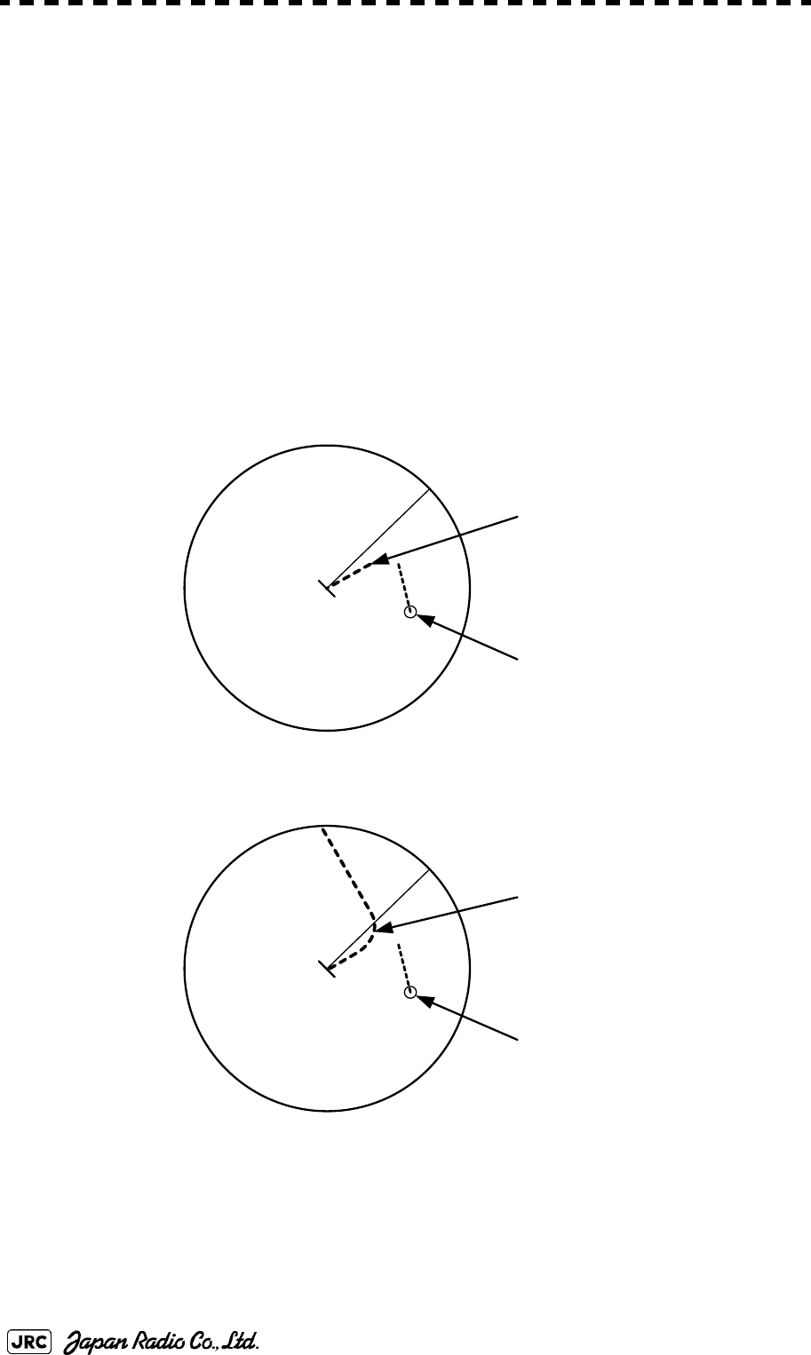
5.7.1 Trial Maneuvering in the True Vector Mode
In the True Vector mode, calculations are performed according to the values set
by Trial Speed, Trial Course and other features, and the result is displayed as a
bold-line that represents the change of own ship's vector as shown in the Fig 5-7
below (an example of the course changed to the right).
In this Fig 5-7, the dangerous target forward left becomes safe as a result of
simulation.
The tracked target information indicates the current CPA and TCPA values
regardless of the result of simulation.
Fig 5-7: True Vector Mode
Dangerous target
HL
Change of symbol
as a result of
trial maneuver
HL
T
TRIAL
NORMAL
Route
Own ship’s vector

JMA-9172-SA Instruction Manual > 5.OPERATION OF TARGET TRACKING AND AIS > 5.7 TRIAL MANEUVERING (Trial Maneuver)
5-55
5
5.7.2 Trial Maneuvering in the Relative Vector Mode
The result of Trial maneuvering in the Relative Vector mode is shown by a
change in target vector. In the Fig 5-8 below (in the same conditions as in the True
Vector mode in the previous page), it is seen that the acquired target is a
dangerous one because its vector is crossing the CPA RING.
Fig 5-8: Relative Vector Mode
The above Fig 5-8 shows that the relative vector of the target has changed as
shown in the figure as a result of simulation (course and speed), so that the
symbol color is changed into “White”, a safe target.
Irrespective of the simulation results, the current CPA and TCPA values are shown
in the tracked target information just like when the true vector mode is active.
The course change of own ship is displayed as a dotted-line.
Better information is provided by using relative motion and sea stabilization.
CPA Ring
Change of symbol
as a result of
trial maneuver
TRIAL
NORMAL
Dangerous target
CPA Ring
HL
HL
T
5-56
JMA-9172-SA Instruction Manual > 5.OPERATION OF TARGET TRACKING AND AIS > 5.7 TRIAL MANEUVERING (Trial Maneuver)
5.7.3 Operation of Trial Maneuvering Function
Procedures
1) Open the Trial Maneuver menu by performing the following menu
operation.
→
2) Left-click the item button of .
The Trial Function will be set to on or off.
When the Trial Function is active, the character " T " will display at the bottom of the radar
display.
3) Set values for Course by turning the [EBL] dial, and for Speed by
turning the [VRM] dial.
4) Set other characteristics.
For inputs to the value input screen, refer to Section 3.3.4.2 "Directly entering a numeric
value".
Dangerous target symbols are displayed in red and safe target symbols in white.
: The trial maneuvering function is turned on.
: The trial maneuvering function is turned off.
: Vector time (1 to 60 min)
: Time until trial maneuvering is started (0 to 30 min)
: Dynamic trait of the own ship
→ : Range from when steered to when the ship
beings to turn (0 to 2000 m)
→ : Turning radius (0.10 to 2.00 nm)
→ : Acceleration (0.0 to 100 knots/min)
→ : Deceleration (0.0 to 100 knots/min)
i
Vector Time is valid only when Trial Function is set to on. If it is off, the vector time
before trial maneuvering is displayed.
Time until the start of trial maneuvering is counted down immediately after the input.
The acceleration and deceleration are influenced depending on the relationship
between the current speed and the input speed for trial maneuvering.
If 0.0 kn/min is set for Acceleration when the speed for trial maneuvering is faster
than the current speed, or for Deceleration when the speed for trial maneuvering is
slower than the current speed, the system performs simulation on the assumption
that the speed is changed immediately after the time set for Time to Maneuver .
TT
3. Trial Maneuver
1. Trial Function
On
Off
Vector Time
Time to Maneuver
Own Ship Dynamic Trait
Reach
Turn Radius
Acceleration
Decceleration

JMA-9172-SA Instruction Manual > 5.OPERATION OF TARGET TRACKING AND AIS > 5.7 TRIAL MANEUVERING (Trial Maneuver)
5-57
5
Cancel
1) Open the Trial Maneuver menu by performing the following
menu operation.
→
2) Left-click the item button of .
The Trial Function will be set to on or off.
:The Trial Function will be set to off.
TT
3. Trial Maneuver
1. Trial Function
Off

5-58
JMA-9172-SA Instruction Manual > 5.OPERATION OF TARGET TRACKING AND AIS > 5.7 TRIAL MANEUVERING (Trial Maneuver)

TRUE AND FALSE ECHOES ON DISPLAY
6.1 RADAR WAVE WITH THE HORIZON ...................................................6-1
6.2 STRENGTH OF REFLECTION FROM THE TARGET ...........................6-3
6.3 SEA CLUTTER AND RAIN AND SNOW CLUTTER ..............................6-5
6.4 FALSE ECHOES ....................................................................................6-9
SECTION 6
TRUE AND FALSE ECHOES ON DISPLAY
JMA-9172-SA Instruction Manual > 6.TRUE AND FALSE ECHOES ON DISPLAY > 6.1 RADAR WAVE WITH THE HORIZON
6-1
6
The radar operator has a role of interpreting the radar displays to provide his best
aid in maneuvering the ship. For this purpose, the operator has to observe the
radar displays after fully understanding the advantages and disadvantages that the
radar has. For better interpretation of radar display, it is important to gain more
experiences by operating the radar equipment in fair weathers and comparing the
target ships watched with the naked eyes and their echoes on the radar display.
The radar is mainly used to monitor the courses of own ship and other ships in
open seas, to check buoys and other nautical marks when entering a port, to
measure own ship’s position in the coastal waters relative to the bearings and
ranges of the shore or islands using a chart, and to monitor the position and
movement of a heavy rain if it appears on the radar display.
Various types of radar display will be explained below.
6.1 RADAR WAVE WITH THE HORIZON
Radar beam radiation has the nature of propagating nearly along the curved
surface of the earth. The propagation varies with the property of the air layer
through which the radar beam propagates. In the normal propagation, the distance
(D) of the radar wave to the horizon is approximately 10% longer than the
distance to the optical horizon. The distance (D) is given by the following
formula:
[NM]
: Height (m) of radar scanner above sea level
: Height (m) of a target above sea level
Fig 6-2 is a diagram for determining the maximum detection range of a target that
is limited by the curve of the earth surface in the normal propagation.
Fig 6-1: RADAR wave with the horizon
D
2.23
h
1
h
2
+()=
h
1
h
2
D
Earth
h
1
h
2
Radar Targets
6-2
JMA-9172-SA Instruction Manual > 6.TRUE AND FALSE ECHOES ON DISPLAY > 6.1 RADAR WAVE WITH THE HORIZON
Fig 6-2: Maximum detection range of a target
When the height of own ship’s scanner is 10 m for instance,
i. A target that can be detected at the radar range of 64 nm on the radar display
is required to have a height of 660 m or more.
ii. If the height of a target is 10 m, the radar range has to be approx. 15 nm.
However, the maximum radar range at which a target can be detected on the
radar display depends upon the size of the target and the weather conditions,
that is, the radar range may increase or decrease depending upon those
conditions.
Height of RADAR Scanner Detective Range Height of Target
D[NM]
JMA-9172-SA Instruction Manual > 6.TRUE AND FALSE ECHOES ON DISPLAY > 6.2 STRENGTH OF REFLECTION FROM THE
TARGET
6-3
6
6.2 STRENGTH OF REFLECTION FROM
THE TARGET
The signal intensity reflected from a target depends not only on the height and size
of the target but also on its material and shape. The echo intensity from a higher
and larger target is not always higher in general.
In particular, the echo from a coast line is affected by the geographic conditions of
the coast. If the coast has a very gentle slop, the echo from a mountain of the
inland appears on the radar display.(Fig 6-3) Therefore, the distance to the coast
line should be measured carefully.
Fig 6-3: Sea shore line which is not displayed
Table 6-1 shows the graph indicating the relation between the target detection
distance and the radar reflection cross-sectional area (RCS) with regard to the type
and the height of the target in a situation in which the weather is good, the sea
state is calm and the radio wave propagation is normal. As revealed by this table,
even on the same sea shore line, detection distance greatly differs depending on
the height of the target from the surface of the sea. Furthermore, because the
target detection distance is greatly influenced by the shape and material of the
target and environmental conditions, such as the sea state, weather, and radio
wave propagation, caution should be taken when detecting distance of target.
Mountain displayed
on the radar display
Sea shore line not displayed
HL
6-4
JMA-9172-SA Instruction Manual > 6.TRUE AND FALSE ECHOES ON DISPLAY > 6.2 STRENGTH OF REFLECTION FROM THE
TARGET
Table 6-1: Relation between type and height of target and detection distance and RCS
Type of target Height from
sea surface
(m)
Detection distance
(NM) RCS
X band S band X band S band
Sea shore line 60 20 20 50,000 50,000
Sea shore line 6 8 8 5000 5000
Sea shore line 3 6 6 2500 2500
SOLAS target ship (>5000GT) 10 11 11 50,000 30,000
SOLAS target ship (>500GT) 5 8 8 1800 1000
Small boat with IMO standard
compatible radar reflector 45.03.77,50,5
Marine buoy with corner
reflector 3,5 4.9 3.6 10 1
Standard marine buoy 3,5 4.6 3.0 5 0,5
10-meter small boat without
radar reflector 23.43.02,51,4
Waterway location beacon 1 2.0 1.0 1 0,1
Detection distance shown in the above table may greatly
decrease depending on the shape of the target, sea state,
weather and radio wave propagation conditions.
m
2
[]
i
JMA-9172-SA Instruction Manual > 6.TRUE AND FALSE ECHOES ON DISPLAY > 6.3 SEA CLUTTER AND RAIN AND SNOW
CLUTTER
6-5
6
6.3 SEA CLUTTER AND RAIN AND SNOW
CLUTTER
In addition to the echo required for observing ships and land, radar video image
also includes unnecessary echo, such as reflection from waves on the sea surface
and reflection from rain and snow. Reflection from the sea surface is called "sea
clutter," and reflection from rain and snow is called "rain and snow clutter," and
those spurious waves must be eliminated by the clutter rejection function.
a. Sea clutter
Sea clutter appears as an image radiating outwardly from the center of the radar
display and changing depending on the size and the shape of waves. Generally, as
waves become larger, image level of the sea clutter is intensified and the clutter
far away is also displayed. When waves are large and the sea clutter level is high,
it is difficult to distinguish sea clutter from a small boat whose reflection intensity
is weak. Accordingly, it is necessary to properly adjust the sea clutter rejection
function. Table 6-2 shows the relation between the sea state (SS) showing the size
of waves generated by wind and the radar's detection probability.
Table 6-2: Sea state and probability of target detection
S band radar (probability to detect a target at a distance of 0.4 NM)
RCS SS1~2SS2~3SS3~4SS4~5
0.1m2 Vi
i. V: Detection probability of 80%
V-Mii
ii. M: Detection probability of 50%
M-NViii
iii. NV: Detection probability of less than 50%
0.5 m2 V V V-M M-NV
1 m2VVVV-M
X band radar (probability to detect a target at a distance of 0.7 NM)
RCS SS1~2SS2~3SS3~4SS4~5
1m2 V-M M-NV
5 m2 V V-M M-NV
10 m2VVVV-M
6-6
JMA-9172-SA Instruction Manual > 6.TRUE AND FALSE ECHOES ON DISPLAY > 6.3 SEA CLUTTER AND RAIN AND SNOW
CLUTTER
As shown in Table 6-2, the number of SS increases as the wind speed becomes
high and the waves become large. Table 6.2 reveals that detection probability
decreases from V (80 %) to NV (less than 50 %) as the number of SS increases.
Therefore, even if the sea state is calm and a target clearly appears on the radar
display, when the sea state becomes rough, target detection probability decreases
resulting in difficulty of target detection by the radar.
For example, in the case of a standard marine buoy, RCS of X band radar is 5 m2
as shown in Table 6-1. When observing such a target in the sea state (SS3) in
which significant wave height exceeds 1.2 meters, detection probability is M-NV,
as shown in Table 6-2, which indicates 50 % or less.
b. Rain and snow clutter
Rain and snow clutter is a video image that appears in a location where rain or
snow is falling. The image changes according to the amount of rain (or the
amount of snowfall). As precipitation increases, the image of rain and snow
clutter becomes intensified on the radar display, and in the case of localized heavy
rain, an image similar to the image indicating land is displayed in some cases.
Furthermore, because radio waves tend to attenuate due to rain and snow, the
ability to detect a target in the rain and snow clutter or a target beyond the rain and
snow clutter may decrease. The amount of attenuation depends on the
transmission frequency, antenna beam width, and the pulse length. Fig 6-4 and
Fig 6-5 show examples in which detection distance is reduced due to the influence
of precipitation. Because of this, a target, which clearly appeared up to 10 NM by
an X band radar (pulse width of 0.8μs) when it was not raining, may become
dimly visible up to 5 NM when the amount of rain becomes 4 millimeters per
hour. Furthermore, when comparing the X band radar with the S band radar,
target detection distance decreases less when the S band radar is used, which
means it is influenced less by precipitation.
Table 6-3: Relation between Douglas sea state and average wind speed and significant
wave height
Sea state Average wind
speed (kn) Significant wave
height (m)i
i. Significant wave height: an average of top N/3 higher waves when
the number of waves detected within a constant time duration is N
0<4<0,2
15-70,6
27-110,9
3 12-16 1,2
4 17-19 2,0
5 20-25 3,0
6 26-33 4,0
JMA-9172-SA Instruction Manual > 6.TRUE AND FALSE ECHOES ON DISPLAY > 6.3 SEA CLUTTER AND RAIN AND SNOW
CLUTTER
6-7
6
0
2
4
6
8
10
12
14
16
0
2
4
6
81012 14 16
降
雨
時
の
検
出
距
離
(NM)
雨の降っていないときの検出距離(NM)
16mm/hr の降雨時 パルス幅 0.05us
4mm/hr の降雨時 パルス幅 0.05us
16mm/hr の降雨時 パルス幅 0.8us
4mm/hr の降雨時 パルス幅 0.8us
Detection distance while it is not rainning[NM]
Detection distance while it is raining [NM]
Precipitation of 16 mm/hr Pulse width 0.8us
Precipitation of 4 mm/hr Pulse width 0.8us
Precipitation of 4 mm/hr Pulse width 0.05us
Precipitation of 16 mm/hr Pulse width 0.05us
Fig 6-4: Decreased target detection distance by S band radar due to
precipitation
0
2
4
6
8
10
12
14
16
024
6810 12 14 16
降
雨
時
の
検
出
距
離
(NM)
16mm/hr の降雨時 パルス幅 0.05us
4mm/hr の降雨時 パルス幅 0.05us
16mm/hr の降雨時 パルス幅 0.8us
4mm/hr の降雨時 パルス幅 0.8us
雨の降っていないときの検出距離(NM)
Detection distance while it is not rainning[NM]
Detection distance while it is raining [NM]
Precipitation of 16 mm/hr Pulse width 0.8us
Precipitation of 4 mm/hr Pulse width 0.8us
Precipitation of 4 mm/hr Pulse width 0.05us
Precipitation of 16 mm/hr Pulse width 0.05us
Fig 6-5: Decreased target detection distance by X band radar due to
precipitation

6-8
JMA-9172-SA Instruction Manual > 6.TRUE AND FALSE ECHOES ON DISPLAY > 6.3 SEA CLUTTER AND RAIN AND SNOW
CLUTTER
c. Coping with sea clutter and rain and snow clutter
When the weather is bad and the ocean is rough, the use of the S band radar is
effective because the radar is not influenced by sea clutter so much and
attenuation due to rain drops is small. When an X band radar is used, reducing the
pulse width will reduce the influence by spurious waves, and also the spurious
wave rejection function effectively works; therefore, the use of short pulse is
effective when the weather is bad. By using image processing functions PROCl 1
to 3, it is expected that spurious waves are further suppressed. Since optimal
settings for those items can be automatically made by using the function mode, it
is recommended that STORM or RAIN be used by selecting the function mode
when the weather is bad. For details of the function mode, see Section 3.9 "USE
FUNCTION KEY [USER]".
However, these functions may make some targets invisible, particularly targets
with higher speeds.
JMA-9172-SA Instruction Manual > 6.TRUE AND FALSE ECHOES ON DISPLAY > 6.4 FALSE ECHOES
6-9
6
6.4 FALSE ECHOES
The radar observer may be embarrassed with some echoes that do not exist
actually. These false echoes appear by the following causes that are well known:
a. Shadow
When the radar scanner is installed near a funnel or mast, the echo of a target that
exists in the direction of the funnel or mast cannot appear on the radar display
because the radar beam is reflected on the funnel or mast. Whether there are some
false echoes due to shadows can be checked monitoring the sea clutter returns, in
which there may be a part of weak or no returns.
Such shadows appear always in the same directions, which the operator should
have in mind in radar operation.
b. Side Lobe Effect
A broken-line circular arc may appear at the same range as the main lobe of the
radar beam on the radar display. This type of false echo can easily be
discriminated when a target echo appears isolated. (see Fig 6-6)
Fig 6-6: False echo
HL
6-10
JMA-9172-SA Instruction Manual > 6.TRUE AND FALSE ECHOES ON DISPLAY > 6.4 FALSE ECHOES
c. False Echo by Secondary Reflection
When a target exists near own ship, two echoes from the single target may appear
on the radar display.
One of those echoes is the direct echo return from the target and the other is the
secondary reflection return from a mast or funnel that stands in the same direction
as shown in Fig 6-7.
Fig 6-7: False echo by secondary reflection
d. False Echo by Multiple Reflection
When there is a large structure or ship with a high vertical surface near own ship
as shown in Fig 6-8, multiple refection returns may appear on the radar display.
These echoes appear in the same intervals, of which the nearest echo is the true
echo of the target.
Fig 6-8: False echo by multiple reflection
e. Second Time Echoes
The maximum radar detection range depends upon the height of the scanner and
the height of a target as described in the Section 6.1 "RADAR WAVE WITH THE
HORIZON". If a so-called “duct” occurs on the sea surface due to a certain
weather condition, however, the radar beam may propagate to a abnormally long
distance, at which a target may be detected by the radar.
Radar
scanner
Funnel
HL
Direct microwave
Secondary reflection
of microwave
Actual target
False echo from funnel
HL
JMA-9172-SA Instruction Manual > 6.TRUE AND FALSE ECHOES ON DISPLAY > 6.4 FALSE ECHOES
6-11
6
For instance, assuming that the pulse length is MP2 (on the repetition frequency
of 2280 Hz), the first pulse is reflected from a target at about 35.5 NM or more
and received during the next pulse repetition time. In this case, a false echo
(second time echo) appears at a position that is about 35.5 NM shorter than the
actual distance. If the false echo appears at 5 NM on the radar display, the true
distance of the target is 5+35.5=40.5 NM. On the pulse length is LP1 (on the
repetition frequency of 1280 Hz), a false echo may appear at a position that is
about 63 NM shorter than the actual distance.
This type of false echo can be discriminated by changing over the range scale (the
repetition frequency), because the distance of the target changes accordingly.
If second time echo is appeared, the use of Economy mode in PRF menu is
effective. Otherwise, Stagger Trigger menu set to on. (See Section 3.8.3 "Set
Scanner Unit (TXRX Setting)").
f. Radar Interference
When another radar equipment using the same frequency band as that on own ship
is near own ship, a radar interference pattern may appear on the radar display.
This interference pattern consists of a number of spots which appear in various
forms. In many cases, these spots do not always appear at the same places, so that
they can be discriminated from the target echoes. (See Fig 6-9)
Fig 6-9: Radar interference
If radar equipment causing an interference pattern and this radar are of the same
model, their transmitting repetition frequency is nearly the same. As a result,
interference patterns may be displayed concentrically.
In this case, the interference patterns cannot be eliminated by using only the
interference reflector function, so ine-tune the transmitting repetition
frequency.(See Section 3.8.3 "Set Scanner Unit (TXRX Setting)")
An interference suppressing effect can be heightened by applying a different
transmitting repetition frequency to the interference pattern source radar and this
radar.
HL HL

6-12
JMA-9172-SA Instruction Manual > 6.TRUE AND FALSE ECHOES ON DISPLAY > 6.4 FALSE ECHOES

SETTINGS FOR SYSTEM OPERATION
7.1 SETTINGS AT INSTALLATION .............................................................7-1
7.1.1 How to Open the Serviceman Menu(Service Man Menu) .........7-1
7.1.2 GYRO I/F Setting .............................................................................7-2
7.1.3 Tuning (Tune Adjustment) .............................................................7-5
7.1.4 Bearing Adjustment ........................................................................7-5
7.1.5 Range Adjustment ...........................................................................7-5
7.1.6 Navigator Setting (Device) .............................................................7-6
7.1.7 Setting of True Bearing Value ........................................................7-7
7.1.8 Antenna Height Setting (Antenna Height) .....................................7-7
7.1.9 Setting of CCRP (CCRP Setting) ....................................................7-8
7.2 SETTINGS ............................................................................................7-11
7.2.1 Communication Port Setting (COM Port Setting) .......................7-11
7.2.2 Sector Blank Setting (Sector Blank) ............................................7-15
7.2.3 Setting of Bearing Pulses from Scanner Unit (Output Pulse) ...7-16
7.2.4 Slave Mode Setting (Master/Slave) ..............................................7-16
7.2.5 Language Setting (Language) ......................................................7-17
7.2.6 Date Time Setting ..........................................................................7-18
SECTION 7
SETTINGS FOR SYSTEM OPERATION
7.2.7 Input Installation Information .......................................................7-19
7.2.8 Setting the Alarm System .............................................................7-19
7.3 ADJUSTMENT ......................................................................................7-24
7.3.1 Noise Level Adjustment (Noise Level) ........................................7-24
7.3.2 Adjustment of Target Tracking Function (TT) ............................7-25
7.3.3 Main Bang Suppression Level Adjustment (MBS) .....................7-27
7.3.4 Adjustment of Performance Monitor ...........................................7-29
7.4 MAINTENANCE MENU ........................................................................7-31
7.4.1 Antenna Safety Switch (Safety Switch) .......................................7-31
7.4.2 Initialization of Memory Area(Area Initial) ...................................7-32
7.4.3 Save of Internal Memory Data (Card1/2) .....................................7-33
7.4.4 Restoration of Scanner Unit Operation Time (TXRX Time) ......7-34
7.4.5 Update of Character String Data (String Data Update) .............7-36
JMA-9172-SA Instruction Manual > 7.SETTINGS FOR SYSTEM OPERATION > 7.1 SETTINGS AT INSTALLATION
7-1
7
7.1 SETTINGS AT INSTALLATION
This section describes the electrical adjustment procedures to be performed by
service engineers during system installation.
The bearing adjustment value is saved to non-volatile memory in the scanner.
Other settings are saviedto non-volatile memory in the radar process unit.
7.1.1 How to Open the Serviceman Menu(Service Man Menu)
Procedures
1) Hold down the button at the
lower right of the display together
with the left key.
The Code Input menu will appear.
2) Left-click the button.
3) Left-click the button.
The Serviceman Menu will appear.
• Do not carry out the adjustments of the equipment
except authorized service persons. If wrong setting is
carried out, this may cause unstable operation.
• Do not carry out the adjustments during navigation.
Otherwise, the radar performance may be affected,
resulting in an accident or trouble.
Fig 7-1: Code Input
Main
0
ENT

7-2
JMA-9172-SA Instruction Manual > 7.SETTINGS FOR SYSTEM OPERATION > 7.1 SETTINGS AT INSTALLATION
7.1.2 GYRO I/F Setting
a. Gyro Settings (STEP or SYNC)
The GYRO I/F circuit of the system is designed to be compatible with most types
of gyro compasses by simply setting the switches.
Before power-on operation can be performed, the switches S1, S2, S5, S6, S7 and
jumper TB105 on the gyro interface circuit (PC4201) must be set in accordance
with the type of your gyro compass by performing the procedure below.
The switches are factory-set for a gyration ratio of 180X and the step motor type.
Make sure of the type of the gyro compass installed on the own ship before
starting the procedure below.
Procedures
1) Set S5 to "OFF".
The gyro compass and GYRO I/F are cut off.
2) Set S6 and S7 in accordance with the type of your gyro compass.
There are two types of gyro compasses: one type outputs a step signal, and the other type
outputs a synchro signal. Make sure of the type of the gyro compass installed on the own
ship before setting the switches S6 and S7.
3) Set the DIP switch S1 in accordance with the type of the
compass.
The items to be set are listed below. For the settings, refer to Table 7-1: Gyro and Log
Select Switches (S1 DIP Switch).
Step motor type: DC24V to DC100V
Synchro-motor type: Primary excitation voltage 50 to 115 VAC
Synchro signal: Set the switches to [SYNC].
Step signal: Set the switches to [STEP].
S1-1: Type of gyro signal (step/synchro)
S1-2/3: Gyration ratio of gyro compass
S1-4: Gyration direction of gyro compass
S1-5: Type of log signal (pulse/synchro)
S1-7/8: Ratio of log signal

JMA-9172-SA Instruction Manual > 7.SETTINGS FOR SYSTEM OPERATION > 7.1 SETTINGS AT INSTALLATION
7-3
7
4) Set the DIP switch S2.
The items to be set are listed below. For the setting, refer to Table 7-2: Gyro and Log Select
Switches (S2 DIP Switch).
5) Confirm the settings of the DIP switch S10.
The DIP switch must be set as shown below. Do not change any of the settings.
6) Set the jumper TB105.
The TB105 is set for using a low-voltage step signal.
7) Connect the gyro signal and log signal cables to the terminal
block.
8) Set S5 to "ON".
The gyro compass and GYRO I/F are connected.
9) After power-on operation, make sure of the radar video and the
operation with the true bearing value.
See the Section 7.1.7 "Setting of True Bearing Value".
10) If the true bearing value of the radar equipment is reversed,
change the setting of the switch S1-4.
1 2 3 4 5 6 7 8
ON OFF OFF OFF ON OFF ON OFF
1 2 3 4 5 6 7 8
OFFOFFOFFOFFOFFOFFOFFOFF
1-2 connected: Setting for normal use
2-3 connected: Setting for a step signal of 22 V or less
7-4
JMA-9172-SA Instruction Manual > 7.SETTINGS FOR SYSTEM OPERATION > 7.1 SETTINGS AT INSTALLATION
Table 7-1: Gyro and Log Select Switches (S1 DIP Switch)
12345678
GYRO SIG
STEP ON
SYNC OFF
360X OFF OFF
180X ON OFF
90X OFF ON
36X ON ON
DIRECTION REV ON
NOR OFF
LOG SIG
TYPE SYNC ON
PULSE OFF
PULSE/
NM Don't care OFF
100P/30X ON ON
200P/90X OFF ON
400P/180X ON OFF
800P/360X OFF OFF
Table 7-2: Gyro and Log Select Switches (S2 DIP Switch)
S2 SETTING TABLE 12345678
OTHER SETTING
LOG ALARM ON
OFF
GYRO SIMULATOR ON
OFF
LOG SIMULATOR ON
OFF
N.A. Don't care any
GYRO ALARM TIME 5s ON
0.2s OFF
HEADING SENSOR SOURCE NMEA(HDT/THS) ON
GYRO SIGNAL OFF
NMEA BAUDRATE SETTING 4800 OFF OFF
9600 ON OFF
19200 OFF ON
38400 ON ON

JMA-9172-SA Instruction Manual > 7.SETTINGS FOR SYSTEM OPERATION > 7.1 SETTINGS AT INSTALLATION
7-5
7
7.1.3 Tuning (Tune Adjustment)
JMA-9172-SA radar is fully automatic. There is no necessary for a tuning
function.
7.1.4 Bearing Adjustment
Make adjustment so that the bearing of the target measured with the ship’s
compass matches the bearing of the target echo on the radar display.
Procedures
1) Select for the bearing presentation. Set video processing
(PROC) to .
2) Measure the bearing of an adequate target (e.g., a ship at anchor,
a breakwater, or a buoy) relative to own ship's heading.
3) Open the Serviceman Menu.
4) Perform the following menu open procedure to open the Bearing
Adjustment menu.
→
For inputs to the value input screen, refer to Section 3.3.4.3 "Increasing or decreasing a
numeric value".
Make adjustment by the 0.1°.
5) Adjust the bearing adjustment value by operating the /
button so that the target measured in step 2) is adjusted to
the correct bearing.
6) Left-click the button to determine the value.
7.1.5 Range Adjustment
Make adjustment so that the range of a target on the radar display is shown
correctly.
Procedures
1) Search the radar display for a target of which range is already
known.
H Up
PROC Off
1. Adjust Menu
2. Bearing Adjustment
+
-
ENT

7-6
JMA-9172-SA Instruction Manual > 7.SETTINGS FOR SYSTEM OPERATION > 7.1 SETTINGS AT INSTALLATION
2) Open the Serviceman Menu.
3) Perform the following menu open procedure to open the Range
Adjustment menu.
→
For inputs to the value input screen, refer to Section 3.3.4.3 "Increasing or decreasing a
numeric value".
4) Adjust the range adjustment value by operating the /
button so that the target measured in step 1) falls in the correct
range.
5) Left-click the button to determine the value.
7.1.6 Navigator Setting (Device)
Determine whether to connect navigators to the radar equipment.
Only the navigators set to ON here can be used.
Procedures
1) Open the Serviceman Menu.
2) Perform the following menu open procedure to open the Device
Installation menu.
→
→
3) Select for navigators connected to the radar equipment,
and for navigators not connected.
Gyro:Gyro (via GYRO I/F)
Compass:Compass (Compliant with IEC61162)
GPS Compass:GPS Compass (JRC)
LOG:Log (via GYRO I/F)
2AXW:2-axis log (Speed over water: Compliant with IEC61162)
2AXG:2-axis log (Speed over ground: Compliant with IEC61162)
1. Adjust Menu
3. Range Adjustment
+-
ENT
2. Installation Menu
9. Next
3. Device Installation
On
Off

JMA-9172-SA Instruction Manual > 7.SETTINGS FOR SYSTEM OPERATION > 7.1 SETTINGS AT INSTALLATION
7-7
7
7.1.7 Setting of True Bearing Value
If GYRO I/F is used to input a gyro signal, the true bearing value indicated by the
master gyro does not match the value indicated by the radar equipment only in a
rare case. In this case, perform the following procedure to adjust the true bearing
value of the radar equipment to the value of the master gyro.
Procedures
1) Perform the following menu open procedure to open the true
bearing value setting menu.
→
→
2) Input the master gyro value to the value input screen.
For inputs to the value input screen, refer to Section 3.3.4.3 "Increasing or decreasing a
numeric value".
7.1.8 Antenna Height Setting (Antenna Height)
Set the height of radar antenna above sea level. Do not change this setting
carelessly.
Procedures
1) Measure the height of radar antenna above sea level in advance.
2) Open the Serviceman Menu.
3) Perform the following menu open procedure to open the Antenna
Height setting menu.
→
→
The Antenna Height menu will open.
GPS:GPS (Compliant with IEC61162)
Main
6. NAV Equipment Setting
1. Gyro Setting
1. Adjust Menu
4. TXRX Adjustment
1. Antenna Height

7-8
JMA-9172-SA Instruction Manual > 7.SETTINGS FOR SYSTEM OPERATION > 7.1 SETTINGS AT INSTALLATION
4) Select the setting that matches the antenna height measured in
step 1).
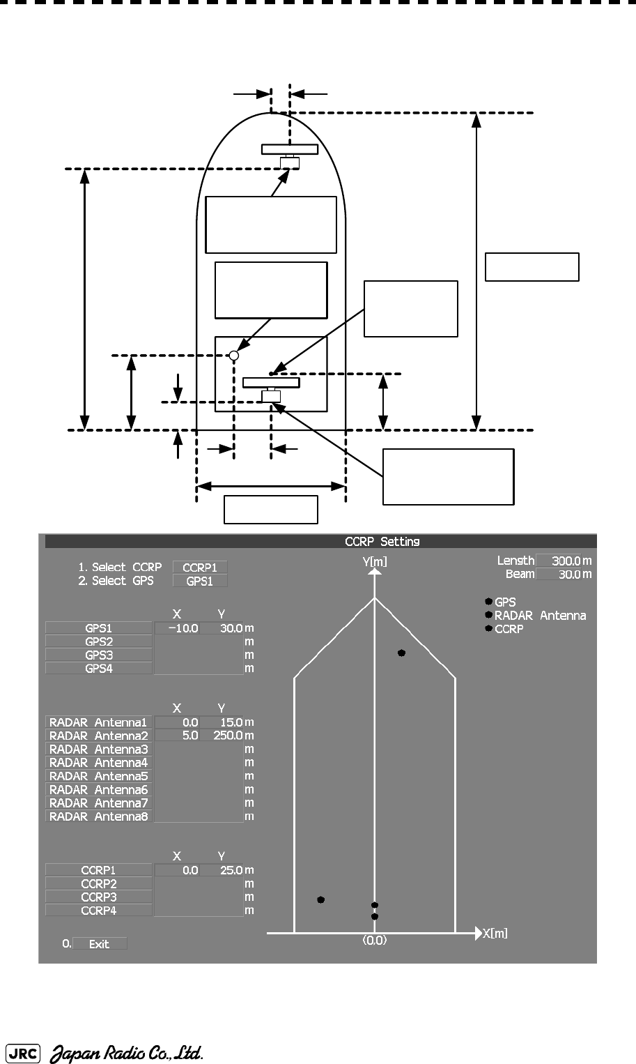
7.1.9 Setting of CCRP (CCRP Setting)
Set the own ship's CCRP location, radar antenna installation location, and GPS
installation location.
Procedures
1) Measure the CCRP location, radar antenna location, and GPS
antenna location in advance.
2) Open the Serviceman Menu.
3) Perform the following menu open procedure to open the CCRP
Setting menu.
→
4) Specify the ship length for Length at the upper right of the CCRP
Setting Menu, and the ship width for Beam.
5) Move the cursor onto the X, Y value, and left-click to
input the CCRP1 location.
When X > 0, the CCRP is on the starboard side of the ship.
When X < 0, it is on the port side.
6) To input the second CCRP, click the button to display the
CCRP2 X,Y value, and input the value in the same manner for
step 5).
Similarly, input the third and subsequent CCRPs.
7) Repeat the above steps to input the GPS location(s) and radar
antenna location(s).
CCRP:Up to four locations can be input. (One location selected when used)
Radar antenna: Up to eight radar antennas can be input. (Automatically selected in
response to ISW operation)
GPS:Up to four locations can be input. (One location selected when used)
2. Installation Menu
4. CCRP Setting
CCRP1
CCRP2

JMA-9172-SA Instruction Manual > 7.SETTINGS FOR SYSTEM OPERATION > 7.1 SETTINGS AT INSTALLATION
7-9
7
8) If multiple CCRP locations and GPS locations are input, select
the CCRP location and GPS location to be used by pressing the
buttons at the upper left of the menu.
9) Click the to close the CCRP Setting menu.
0.Exit
7-10
JMA-9172-SA Instruction Manual > 7.SETTINGS FOR SYSTEM OPERATION > 7.1 SETTINGS AT INSTALLATION
Length 300m
Beam 30m
RADAR Antenna1
X 0m, Y 15m
GPS1
X -10m, Y 30m
RADAR Antenna2
X 5m, Y 250m
30m
250 m
15m
10m
5m
25m
CCRP1
X 0m, Y 25m
Example:
JMA-9172-SA Instruction Manual > 7.SETTINGS FOR SYSTEM OPERATION > 7.2 SETTINGS
7-11
7
7.2 SETTINGS
This section describes the electrical adjustment procedures to be performed by
service engineers during system installation.
7.2.1 Communication Port Setting (COM Port Setting)
External sensor signals are input to the radar equipment through a communication
port. The radar equipment has ten communication ports. For signals to be input
from sensors or to be output to the sensors, communication ports need to be set in
accordance with the sensors.
7.2.1.1 Baud Rate Setting (Baud Rate)
Set the baud rate of the signal to be input to the COM port.
Procedures
1) Open the Serviceman Menu.
2) Perform the following menu open procedure to open the Baud
Rate setting menu.
→
→
• Do not carry out the adjustments of the equipment
except authorized service persons. If wrong setting is
carried out, this may cause unstable operation.
• Do not carry out the adjustments during navigation.
Otherwise, the radar performance may be affected,
resulting in an accident or trouble.
2. Installation Menu
5. COM Port Setting
1. Baud Rate

7-12
JMA-9172-SA Instruction Manual > 7.SETTINGS FOR SYSTEM OPERATION > 7.2 SETTINGS
3) Set the baud rate of the port to be set.
7.2.1.2 Reception Port Setting(RX Port)
Set the numbers of ports for receiving signals from sensors.
There are two methods for receiving signals: specifying a port for each sensor, or
using the automatic recognition function without specifying ports.
Procedures
1) Open the Serviceman Menu.
2) Perform the following menu open procedure to open the RX Port
setting menu.
→
→
3) Set a port for each sensor.
1. COMPASSi:
i. The compass port is a receive-only port that is dedicated to COMPASS signals.
4800(NMEA)/9600(NSK)/38400(fast NMEA)ii bps
ii. The bold values are factory-set.
2. MAINTENANCE/LOG:1200/4800/9600/38400 bps
3. NAV1:1200/4800/9600/38400 bps
4. NAV2:1200/4800/9600/38400 bps
5. ALARM:1200/4800/9600/38400 bps
6. JARPAiii:
iii. The JARPA port is a transmit-only port that is dedicated to JRC ARPA signals.
1200/4800/9600/38400 bps
7. AIS:1200/4800/9600/38400 bps
8. ARPAiv:
iv. The ARPA port is a transmit-only port.
1200/4800/9600/38400 bps
9. COMv:
v. The COM port connector is D-sub 9pin.
1200/4800/9600/38400/115200 bps
Settable sensor
signals GPS、DLOG、Alarm、Depth、Temperature、Wind、Current、
ROT、RSA
Selectable ports When the automatic recognition
function is used: AUTO
When ports are specified: LOG、NAV1、NAV2、
ALARM、COM
2. Installation Menu
5. COM Port Setting
2. RX Port

JMA-9172-SA Instruction Manual > 7.SETTINGS FOR SYSTEM OPERATION > 7.2 SETTINGS
7-13
7
7.2.1.3 Reception Sentence Setting (RX Sentence)
Set signal sentences to be received from sensors.
The system is factory-set for using all sentences. To receive only specified
sentences, select for sentences which are not necessary.
Procedures
1) Open the Serviceman Menu.
2) Perform the following menu open procedure to open the RX
Sentence setting menu.
→
→
3) Select the sentences to be used by the sensors to be set.
Selection value: or can be set for each sentence.
1. GPS(LL/COG/SOG):GGA/RMC/RMA/GNS/GLL/VTG
2. GPS(WPT/Time):GGA/RMC/RMB/BWC/BWR/ZDA
3. Depth:DPT/DBK/DBT/DBS
4. Wind:MWV/MWD
5. Current:
→Data Set Number:0-9. Set the number of the sentence to be used by Data
Set Number. (Initial value 0)
→Layer A:Set the number of the sentence to be used with layer A
by Layer Number. (Initial value 3)
→Layer B:Set the number of the sentence to be used with layer B
by Layer Number. (Initial value 4)
→Layer C:Set the number of the sentence to be used with layer C
by Layer Number. (Initial value 5)
6. Autopilot:APB
No Use
2. Installation Menu
5. COM Port Setting
3. RX Sentence
Use
No Use

7-14
JMA-9172-SA Instruction Manual > 7.SETTINGS FOR SYSTEM OPERATION > 7.2 SETTINGS
7.2.1.4 Transmission Port Setting (TX Port)
For each sentence, set a communication port through which signals are
transmitted to sensors.
Procedures
1) Open the Serviceman Menu.
2) Perform the following menu open procedure to open the TX Port
setting menu
→
→
3) Select the communication port through which the sentence to be
set is output.
4) Select the output format, talker, and transmission interval.
Signals for which the above items can be set:
Settable sentences TTM(TT)、TLL(TT)、TTD(TT)、TLB(TT)、OSD、RSD、ALR、
ACK、TTM(AIS)、TLL(AIS)、TTD(AIS)、TLB(AIS)、
RemoteMaintenance、JRC-ARPA、APB、BOD、GGA、GLL、
RMC、RMB、VTG、XTE、BWC、HDT、THS
Selectable ports MAINTENANCE、NAV1、NAV2、ALARM、JARPA、ARPA、
COM
Item Name Option
NMEA0183
Output Format APB, BOD, GGA,
GLL, RMC, RMB,
VTG, XTE, BWC,
HDT
V1.5
V2.0
V2.3i
i. The bold values are factory-set.
NMEA0183
Talkerii
ii. For TTM, TLL, OSD, RSD, and ALR, the talker is always RA .
For GGA, GLL, RMC, and VTG, the talker is always GP.
APB, BOD,RMB,
XTE, BWC, HDT,
THS
STANDARD:The talker is RA .
GP:The talker is GP.
NMEA0183 TX
Interval APB, BOD, GGA,
GLL, RMC, RMB,
VTG, XTE, BWC,
HDT, THS
Set an interval in the range 1 to 9 seconds.
2. Installation Menu
5. COM Port Setting
4. TX Port

JMA-9172-SA Instruction Manual > 7.SETTINGS FOR SYSTEM OPERATION > 7.2 SETTINGS
7-15
7
7.2.2 Sector Blank Setting (Sector Blank)
In order not to display radar echoes, set a sector range and stop transmission in the
bearing range. Three types of sectors can be created.
The sector blank function operates in the relative bearing with the bow as the
benchmark.
7.2.2.1 Sector Blank Function On/Off (Sector1,2 and 3)
Procedures
1) Open the Serviceman Menu.
2) Perform the following menu open procedure to open the Sector
Blank setting menu.
→
3) Set the sector blank number , , or with
which the sector blank function operates.
The system allows the use of up to three sector blank areas.
Set each sector blank area to on or off.
7.2.2.2 Sector Blank Area Creation (Make Sector 1,2,3)
Procedures
1) Open the Serviceman Menu.
2) Perform the following menu open procedure to open the Sector
Blank setting menu.
→
3) Select the sector blank number ( to ) for
sector creation, and click the Make Sector button in the menu.
The selected sector blank will be made.
: The sector blank function of the number is operated.
: The sector blank function of the number is stopped.
2. Installation Menu
3. Sector Blank
Sector 1 Sector 2 Sector 3
On
Off
2. Installation Menu
3. Sector Blank
Make Sector 1 Make Sector 3

7-16
JMA-9172-SA Instruction Manual > 7.SETTINGS FOR SYSTEM OPERATION > 7.2 SETTINGS
4) Set the starting azimuth of the sector blank by operating the
[EBL] dial, and left-click the button.
The start angle of the sector blank will be set.
5) Set the ending azimuth of the sector blank by operating the [EBL]
dial, and left-click the button.
The end angle of the sector blank will be set.
7.2.3 Setting of Bearing Pulses from Scanner Unit (Output Pulse)
Set the output value of bearing pulses from the scanner unit. The system can set
2048 pulses or 4096 pulses. This setting is enabled only when the scanner unit of
25 or 30 kW is used.
Procedures
1) Open the Serviceman Menu.
2) Perform the following menu open procedure to open the Output
Pulse setting menu.
→
→
3) Set the number of pulses to be output by the scanner unit.
7.2.4 Slave Mode Setting (Master/Slave)
Place the system in the Slave mode when it is to be operated as the sub-display
that displays radar echoes by using radar signals from other radar equipment.
The input value of externally input bearing pulses can be set. The system can set
2048 pulses or 4096 pulses.
i
i. If a 10 kW antenna is used, 2048 is always set.
:2048 pulses per antenna rotation (Recommended value)
:4096 pulses per antenna rotation
ENT
ENT
1. Adjust Menu
4. TXRX Adjustment
6. Output Pulse
2048
4096
JMA-9172-SA Instruction Manual > 7.SETTINGS FOR SYSTEM OPERATION > 7.2 SETTINGS
7-17
7
7.2.4.1 Slave Mode Setting (Master/Slave)
Procedures
1) Open the Serviceman Menu.
2) Perform the following menu open procedure to open the
installation setting menu.
3) Select Slave for the item in the menu.
7.2.4.2 Setting of Input Bearing Pulse (Input BP Pulse)
Procedures
1) Open the Serviceman Menu.
2) Perform the following menu open procedure to open the second
page of the installation setting menu.
→
3) Set the number of pulses for the item in the
menu.
7.2.5 Language Setting (Language)
The system is designed to switch between display languages, Japanese and
English.
Procedures
1) Open the Serviceman Menu.
:The system operates as radar equipment while the own
antenna is connected.
:The system operates as a sub-display while the signal
cable of other radar equipment is connected.
:2048 pulses per antenna rotation
:4096 pulses per antenna rotation
2. Installation Menu
2. Master Slave
Master
Slave
2. Installation Menu
9. Next
1. Input BP Count
2048
4096

7-18
JMA-9172-SA Instruction Manual > 7.SETTINGS FOR SYSTEM OPERATION > 7.2 SETTINGS
2) Perform the following menu open procedure to open the
language setting menu.
→
3) Select the language to be used.
7.2.6 Date Time Setting
To display time, the local time, local date, and time-zone difference must be set.
However, if the "ZDA" sentence of NMEA0183 is received, time can be
automatically displayed.
Procedures
1) Perform the following menu open procedure to open the Date
Time setting menu.
→
→
The Date Time Setting menu will open.
2) Set information about date and time
2)-1. UTC/LMT (Time display system)
2)-2. LMT Date
Input the date in local time.
2)-3. LMT Time
Input the date in local time.
2)-4. Time Zone
Input the time-zone difference between the universal time and local time.
i
i. Other is an option to display character strings created by our overseas agents.
Ask the overseas agent or our sales department if your language is supported. To
determine the selected language, turn the power off, and then turn it on.
: Universal Time Coordinate
: UTC (System Time)
: Local Mean Time
: LMT (System Time)
2. Installation Menu
8. Language
1. English
2. Japanese
3. Other
Main
7. Sub Menu
6. Date Time Setting
UTC
UTC (S)
LMT
LMT (S)

JMA-9172-SA Instruction Manual > 7.SETTINGS FOR SYSTEM OPERATION > 7.2 SETTINGS
7-19
7
2)-5. Display Style
2)-6. Synchronize with GPS
7.2.7 Input Installation Information
The system can input installation information.
Procedures
1) Open the Serviceman Menu.
2) Perform the following menu open procedure to open the
Installation Information setting menu.
→
3) Input the installation information.
For the input method on the numeric value and character input screens, see Section 3.3.4
"Operation on Numeric Value, Latitude / Longitude and Character Input menu".
7.2.8 Setting the Alarm System
7.2.8.1 Setting the reset interval (Reset Interval)
This function enables the control of WMRST terminal (on the terminal board
circuit).The reset signal is turned on when operation in a set period of time.
Set one of the following date display formats.
ex) 2007-12-31
ex) DEC 31, 2007
ex) 31 DEC, 2007
A ZDA sentence sent by the GPS is used, thereby displaying time
synchronized with the GPS time.
i:
i. If On is selected for this item but a ZDA sentence is not input, the system
internal clock function is used to display the date and time.
Time synchronized with the GPS time
:Time not synchronized with the GPS time
Input the date of installed system.
Input the name of installation personel.
Input the name of radar installer.
YYYY-MM-DD
MMM DD, YYYY
DD MMM, YYYY
On
Off
Main
1. Installation Information
Date
Name
Company

7-20
JMA-9172-SA Instruction Manual > 7.SETTINGS FOR SYSTEM OPERATION > 7.2 SETTINGS
Procedures
1) Open the Serviceman Menu.
2) Perform the following menu open procedure to open the Reset
Interval menu.
→
→
→
3) Input the value to be set.
For how to input numeric data on the numeric value input screen, see Section 3.3.4
"Operation on Numeric Value, Latitude / Longitude and Character Input menu".
7.2.8.2 Setting the Trackball Threshold
This function enables the control of WMRST terminal (on the terminal board
circuit).
The reset signal is turned off when trackball is moved, that caused by vibration.If
trackball move distance go over the threshold (dot unit) when reset signal is
turned on.
Procedures
1) Open the Serviceman Menu.
2) Perform the following menu open procedure to open the
Trackball Threshold menu.
→
→
→
3) Input the value to be set.
For how to input numeric data on the numeric value input screen, see Section 3.3.4
"Operation on Numeric Value, Latitude / Longitude and Character Input menu".
7.2.8.3 Setting the relay output (Relay Output)
This function enables the control of ARPAALM terminal (on the terminal board
circuit).
Procedures
1) Open the Serviceman Menu.
2. Installation Menu
6. Alarm System
1. Watch Alarm
1. Reset Interval
2. Installation Menu
6. Alarm System
1. Watch Alarm
2. Trackball Threshold

JMA-9172-SA Instruction Manual > 7.SETTINGS FOR SYSTEM OPERATION > 7.2 SETTINGS
7-21
7
2) Perform the following menu open procedure to open the Relay
Output menu.
→
→
3) Left-click the button in the menu.
The Relay Output mode is switched.
4) Click the item button corresponding to the item to be changed.
The item can be turned on / off.
7.2.8.4 Setting the ALR output (ALR Output)
This function enables the control of ALR port (See Section 7.2.1 "Communication
Port Setting (COM Port Setting)").
Procedures
1) Open the Serviceman Menu.
2) Perform the following menu open procedure to open the ALR
Output menu.
→
→
: The output is continuously controlled.
: The output is intermittenly controlled.
: The relay output is turned on when alarm have issued.
: The relay output is not turned on when alarm have issued.
: There is a dangerous target. (tracked target)
: There is a dangerous target. (AIS target)
: A new target is acquired in the automatic acquisition zone.
: There is a lost target. (Target Tracking / AIS).
2. Installation Menu
6. Alarm System
2. Relay Output
1. Relay Output Mode
Continuous
Intermittent
On
Off
2. TT CPA/TCPA
3. AIS CPA/TCPA
4. New Target
5. Lost
2. Installation Menu
6. Alarm System
2. Relay Output

7-22
JMA-9172-SA Instruction Manual > 7.SETTINGS FOR SYSTEM OPERATION > 7.2 SETTINGS
3) Click the item button corresponding to the item to be changed.
The item is turned on / off.
7.2.8.5 Setting the External Acknowledgement (External ACK Setting)
This function enables the control of system when ACK sentence have received.
Procedures
1) Open the Serviceman Menu.
2) Perform the following menu open procedure to open the External
ACK Setting menu.
→
→
3) Click the item button corresponding to the menu to be changed.
: The ALR sentence is output when alarm have issued.
: The ALR sentence is not output when alarm have issued.
: The internal alarm.
: Target Tracking Alarms and AIS Function Alarms.
:CPA/TCPA alarm.
:Exept Critical Alarm.
On
Off
1. System Alarm
2. TT/AIS Alarm
2. Installation Menu
6. Alarm System
5. External ACK Setting
Critical Alarm
Normal Alarm
JMA-9172-SA Instruction Manual > 7.SETTINGS FOR SYSTEM OPERATION > 7.2 SETTINGS
7-23
7
4) Click the item button corresponding to the item to be changed.
The item is switched.
7.2.8.6 Setting the Alarm Buzzer (Sound Output Mode)
This function enables the control of alarm buzzer.
Procedures
1) Open the Serviceman Menu.
2) Perform the following menu open procedure to open the External
ACK Setting menu.
→
→
3) Select the function to be used.
, and
Setting and Ararm Function
①: Followed by Buzzer Volume menu setting.
②: Alarm Buzzer is turned off.
③: If Relay Output menu is turned on when Alam Buzzer is turned off. If Relay Output menu is turned off when Alam
Buzzer is turned on.
For how to setting Buzzer Volume menu, see Section 3.8.6 "Adjust Sound Volume (Buzzer Volume)".
: Setting of alarm sound.
→: The alarm sound is not stopped when
acknowridgement have received.
→: The alarm sound is stopped when
acknowridgement have received.
: Setting of alarm indication.
→: The alarm indication brinking is stopped when
acknowridgement have received.
→: The alarm indication brinking is not stopped
when acknowridgement have received.。
: Setting of ALR sentence.
→: Add acknowridgement to ALR sentence.
→: Add no acknowridgement (unrecognized) to ALR
sentence.
Alarm Setting Operation Operation
Miss CPA/
TCPA New
Target Lost NAV System ISW
①
①②
①③①②①
Audio
On
Off
Indication
Lightning
Brinking
Acknowledge State
A;ACK
V;UNACK
2. Installation Menu
6. Alarm System
4. Sound Output Mode
On
Off1 Off2
On
Off1
Off2
7-24
JMA-9172-SA Instruction Manual > 7.SETTINGS FOR SYSTEM OPERATION > 7.3 ADJUSTMENT
7.3 ADJUSTMENT
This section describes the electrical adjustment procedures to be performed by
service engineers during system installation.
7.3.1 Noise Level Adjustment (Noise Level)
7.3.1.1 Noise Level Adjustment for Signal Processing
Procedures
1) Open the Serviceman Menu.
2) Perform the following menu open procedure to open the noise
level adjustment menu.
→
→
3) Increase/decrease the noise level adjustment value.
The noise level is factory-set. (Initial value: 140)
After system installation, a great change in the noise level adjustment value should be
avoided; it should be fine adjusted within ±5.
Do not carry out the adjustments of the equipment
except authorized service persons. If wrong setting is
carried out, this may cause unstable operation.
Do not carry out the adjustments during navigation.
Otherwise, the radar performance may be affected,
resulting in an accident or trouble.
9. RADAR/TT Initial Setup
1. Signal Processing
1. Echo Noise Level

JMA-9172-SA Instruction Manual > 7.SETTINGS FOR SYSTEM OPERATION > 7.3 ADJUSTMENT
7-25
7
7.3.1.2 Noise Level Adjustment Mode (Setting Mode)
A noise level is factory-adjusted while this mode is turned on.
Procedures
1) Open the Serviceman Menu.
2) Perform the following menu open procedure to open the noise
level adjustment menu.
→
→
The noise level adjustment mode is switched between on and off.
7.3.2 Adjustment of Target Tracking Function (TT)
7.3.2.1 Vector Constant Adjustment (Vector Constant)
Adjust the vector follow-up performance of the target tracking function.
The vector constant is adjusted to an optimal value, so do not change it carelessly.
Procedures
1) Open the Serviceman Menu.
2) Perform the following menu open procedure to open the Vector
Constant adjustment menu.
Factory-adjustment method
・The noise level adjustment value is once decreased to about 130.
・While the noise level adjustment value is gradually increased, the value
with which radar echoes start turning yellow is determined as the set
value.
・The noise level adjustment mode is turned off when the adjustment is
finished.
Do not change the set value carelessly.
The vector constant shall be set to 5 normally. If the vector
constant value is higher, a target’s vector will be better followed
up when the target and own ship change their course or speed,
but the vector accuracy will be lower on the contrary.
9. RADAR/TT Initial Setup
1. Signal Processing
2. Setting Mode
Attention
7-26
JMA-9172-SA Instruction Manual > 7.SETTINGS FOR SYSTEM OPERATION > 7.3 ADJUSTMENT
→
→
The window for setting vector constants will appear.
3) Input the value to be set.
For how to input numeric data on the numeric value input screen, see Section 3.3.4
"Operation on Numeric Value, Latitude / Longitude and Character Input menu".
7.3.2.2 Quantization Level Adjustment (Video TD Level)
Use the target tracking function (TT) to adjust the level of the signal to be
recognized as a target. If a small value is set, even weak target signals will be
input to the target detection circuit of the target tracking function. However, many
unnecessary signals are also input, which may cause unstable target acquisition or
tracking. It is important to set a value four or five greater than the value with
which unnecessary signals are detected.
The quantization level is adjusted to an optimal value, so do not change it
carelessly.
Procedures
1) Open the Serviceman Menu.
2) Perform the following menu open procedure to open the target
tracking setting menu.
→
3) To change the quantization level of the automatic acquisition
area, specify the item in the menu. To change
the quantization level of tracking and manual acquisition, specify
the item .
4) Input the value to be set.
Do not change the set quantization level carelessly. If
the level deviates from the proper value, the target
acquisition and tracking functions will deteriorate.
Otherwise, this may cause accidents.
9. RADAR/TT Initial Setup
2. TT
1. Vector Constant
9. RADAR/TT Initial Setup
2. TT
2. Video TD Level
3. Video High Level
JMA-9172-SA Instruction Manual > 7.SETTINGS FOR SYSTEM OPERATION > 7.3 ADJUSTMENT
7-27
7
7.3.3 Main Bang Suppression Level Adjustment (MBS)
Main Bang Suppression is adjusted to suppress main bang, a reflection signal
from 3D circuit including wave guide tube, that generally appears as a circular
image focusing on the center of the radar display. Optimum adjustment allows
main bang image to remain lightly on the display.
7.3.3.1 Adjustment of Main Bang Suppression Level (MBS Level)
Procedures
1) Open the Serviceman Menu.
2) Perform the following menu open procedure to open the MBS
level adjustment menu.
→
→
3) Set the radar as follows:
•Set the radar range to 0.125 NM.
•Set the radar video enhance function (ENH) to OFF.
•Set the image processing (PROC) to OFF.
•Turn the [RAIN] control to the minimum position (fully to the left).
•Turn the [GAIN] control to the maximum position (fully to the right).
•Turn the [SEA] control to achieve the strength with which main bang can be judged.
4) Adjust the value so that the main bang can be erased.
Do not change this adjusted level carelessly.
Incorrect adjustment may erase targets in point-blank
range and cause collision, resulting in death or serious
injury.
9. RADAR/TT Initial Setup
3. MBS
1. MBS Level

7-28
JMA-9172-SA Instruction Manual > 7.SETTINGS FOR SYSTEM OPERATION > 7.3 ADJUSTMENT
7.3.3.2 Adjustment of Main Bang Suppression Area (MBS Area)
Procedures
1) Open the Serviceman Menu.
2) Perform the following menu open procedure to open the MBS
Area adjustment menu.
→
→
3) Set the radar as follows:
•Set the radar range to 0.125 NM.
•Set the radar video enhance function (ENH) to OFF.
•Set the image processing (PROC) to OFF.
•Turn the [RAIN] control to the minimum position (fully to the left).
•Turn the [GAIN] control to the maximum position (fully to the right).
•Turn the [SEA] control to achieve the strength with which main bang can be judged.
4) Adjust the value so that the main bang can be erased.
9. RADAR/TT Initial Setup
3. MBS
2. MBS Area
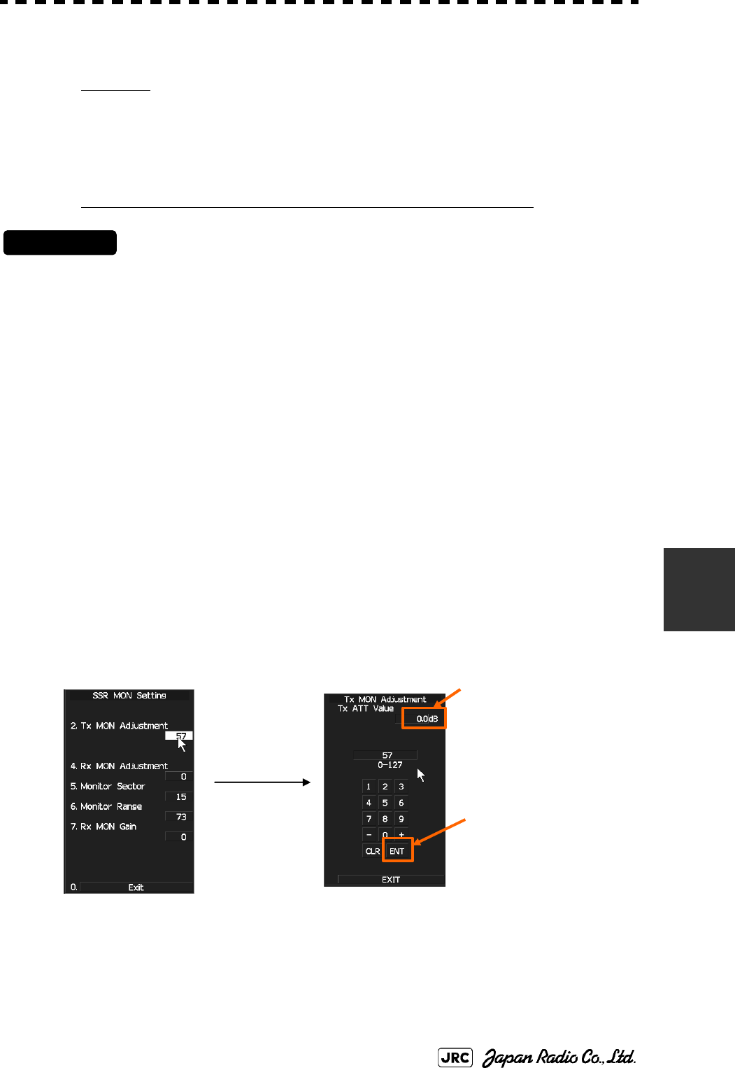
JMA-9172-SA Instruction Manual > 7.SETTINGS FOR SYSTEM OPERATION > 7.3 ADJUSTMENT
7-29
7
7.3.4 Adjustment of Performance Monitor (SSR MON)
Attension
Replace the Antenna unit, TRX Module(CMN-750), performance monitor circuit
(CAY-71), and radar process circuits (CHA-396, CDC-1349, CMH-2246), adjust
the perfomance monitor according to the procedures in this section:
[i] Transmission Monitor Adjustment (Tx MON Adjustment)
Procedures
1) Set the master display unit for radar with the inter-switch
function. (Interswitch is un-available for evaluation model.)
2) Open the Serviceman Menu.
3) Perform the following menu open procedure to open the “Tx
Monitor Adjustment” menu.
1.Adjust Menu
→4.TXRX Adjustment
→7.SSR MON Setting
→2. Tx MON Adjustment
4) Adjust the “Tx MON Adjustment” value to “0.0 ± 1.0dB” by
operating the “+” / “-” button.
5) Left-click the “ENT” button.
A
d
j
ust to “0.0±1.0dB”
4
3
5
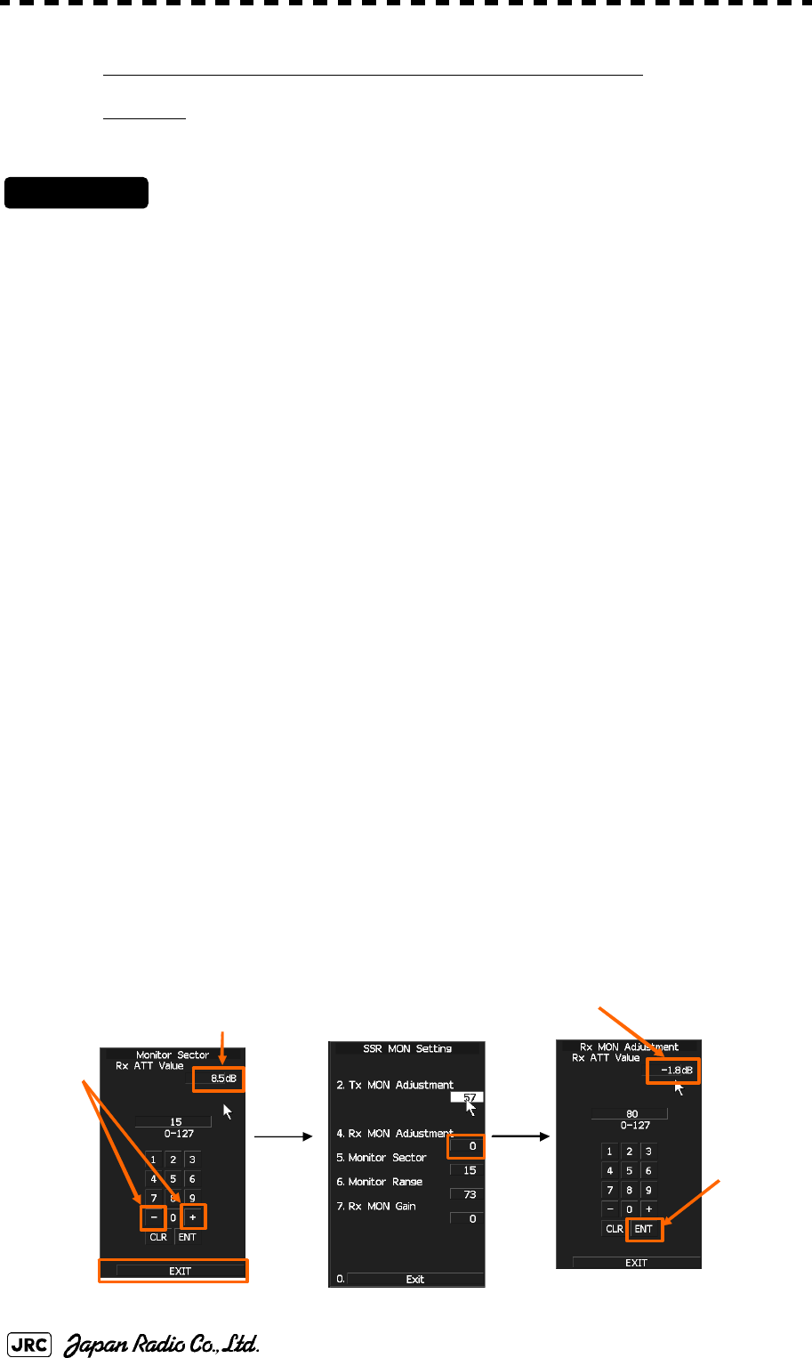
7-30
JMA-9172-SA Instruction Manual > 7.SETTINGS FOR SYSTEM OPERATION > 7.3 ADJUSTMENT
[ii] Receiver Monitor Adjustment (Rx MON Adjustment)
Attension
Do not change the parameters of “6. Monitor Range” and “7.Rx MON Gain”.
Procedures
1) Set the master display unit for radar with the inter-switch
function. (Interswitch is un-available for evaluation model.)
2) Open the Serviceman Menu.
3) Perform the following menu open procedure to open the “Tx
Monitor Adjustment” menu.
1.Adjust Menu
→4.TXRX Adjustment
→7.SSR MON Setting
→5. Monitor Sector
4) The +/- button is operated so that "Rx ATT Value" may become
the maximum.
*The PM Rx area(22.5
°
) displayed on the PPI screen moves to
operate "+/-" button.
5) Perform the following menu open procedure to open the “Rx
MON Adjustment” menu.
6) Adjust the “Rx MON Adjustment” value to “0.0 ± 1.0dB” by
operating the “+” / “-” button.
7) Left-click the “ENT” button.
M
a
xim
u
m
A
d
j
ust to “0.0dB±1.0dB”
5.
3. 6.
7
5.
4.
JMA-9172-SA Instruction Manual > 7.SETTINGS FOR SYSTEM OPERATION > 7.4 MAINTENANCE MENU
7-31
7
7.4 MAINTENANCE MENU
This item is provided for equipment maintenance, including settings of antenna
safety switch, master reset, etc.
7.4.1 Antenna Safety Switch (Safety Switch)
Use this switch to measure the transmission/reception performance while the
antenna is in stopped state.
Procedures
1) Open the Serviceman Menu.
2) Perform the following menu open procedure to open the Safety
Switch setting menu.
→
3) Select the item to be set.
Set operation when the antenna safety switch is turned off.
4) Change the setting back to when the work is finished.
Only our service engineers are to make the
adjustment. Neglecting this caution may cause
accidents and failures.
Do not make the adjustments during navigation.
Otherwise, adjustments may affect the radar functions,
causing accidents and failures.
:The transmitter stops transmission. The screen on the
display unit remains in transmission state.
:(Normal setting) The transmitter stops transmission. The
screen on the display unit is placed in standby state.
:The transmitter continues transmission. The screen on the
display unit remains in transmission state. In this case,
however, an error such as a bearing signal failure occurs
because the safety switch is turned off.
3. Maintenance Menu
1. Safety Switch
1. TX-OFF
2. Standy
3. TX-ON
2. Standy

7-32
JMA-9172-SA Instruction Manual > 7.SETTINGS FOR SYSTEM OPERATION > 7.4 MAINTENANCE MENU
7.4.2 Initialization of Memory Area(Area Initial)
If system operation is unstable, it may be stabilized by initializing the memory
area. To initialize the memory area, follow the procedure in this section. The
memory area is reset to the factory setting when initialized.
7.4.2.1 Partial Master Reset
Procedures
1) Open the Serviceman Menu.
2) Perform the following menu open procedure to open the Partial
Master Rest operation menu for the memory area.
→
→
3) Select the items to be initialized.
4) Select in the Confirmation Menu.
The memory areas of specified items are initialized, and the system is restarted.
7.4.2.2 All Master Reset
Procedures
1) Open the Serviceman Menu.
2) Perform the following menu open procedure to open the All
Master Rest operation menu for the memory area.
→
→
3) Select in the Confirmation Menu.
The whole memory area is initialized, and the system is restarted.
:The set values in the Serviceman menu are initialized.
:The set values not in the Serviceman menu are initialized.
:The user-set values are initialized.
:The set values for the target tracking function are initialized.
:The set values for the AIS display function are initialized.
:The color scheme and brilliance setting for the day/night
mode are initialized.
3. Maintenance Menu
2. Area Initial
1. Partial Master Reset
1. Serviceman Menu
2. Except Serviceman Menu
3. User Setting
4. TT Setting
5. AIS Setting
6. Day/Night
1. Yes
3. Maintenance Menu
2. Area Initial
2. All Master Reset
1. Yes
JMA-9172-SA Instruction Manual > 7.SETTINGS FOR SYSTEM OPERATION > 7.4 MAINTENANCE MENU
7-33
7
7.4.3 Save of Internal Memory Data (Card1/2)
The system can save internal memory data such as item settings in all menus onto
a flash memory card. If the radar processing circuit in the system has been
replaced, the set values before the circuit replacement can be restored by reading
the set values you saved before the replacement.
To save the internal memory data onto a flash memory card (option), the card
must be inserted in card slot beforehand.
7.4.3.1 Copying of Internal Settings onto Card (Internal To Card1/2)
Save the internal memory data, such as item settings in menus, onto a flash memory card.
The internal memory data should be saved at completion of system setting, and the operation
condition should be saved periodically.
Procedures
1) Open the Serviceman Menu.
2) Open the .
3) Select in the .
4) Select in the Confirmation Menu.
The internal memory data is saved on the flash memory card.
7.4.3.2 Reading of Internal Settings from Card (Card1/2 To Internal)
Read the saved memory data from the flash memory card into the system memory.
Perform the read operation in order to return the system to the previous operation condition
after replacement of the radar processing circuit in the system.
Procedures
1) Open the Serviceman Menu.
2) Open the .
3) Select in the .
4) Select in the Confirmation Menu.
The memory data is read from the flash memory card into the system memory.
After the internal memory area is updated, the system is restarted.
3. Maintenance Menu
Slot2
3. Internal To Card1/2
1. Yes
3. Maintenance Menu
Slot2
4. Card1/2 To Internal
1. Yes

7-34
JMA-9172-SA Instruction Manual > 7.SETTINGS FOR SYSTEM OPERATION > 7.4 MAINTENANCE MENU
7.4.4 Restoration of Scanner Unit Operation Time (TXRX Time)
The system adds up the following operation time and contains it in the scanner
unit:
•Transmission time
•Motor run time
Clear the above total time when scanner unit motor is replaced.
7.4.4.1 Clear of Motor Run Time (Clear TX Time)
Clear the scanner's motor run time.
Perform the following procedure to clear the motor run time when the scanner motor is
replaced.
Procedures
1) Open the Serviceman Menu.
2) Perform the following menu open procedure to open the Clear
Motor Time menu.
→
→
3) Select in the Confirmation Menu.
The motor run time in the TXRX's internal control circuit is cleared to 0.
7.4.4.2 Save of Antenna Time (Clear Motor Time)
Save the following scanner unit time data from the scanner unit into the display unit.
Perform the following procedure to inherit the scanner unit time data when the TXRX's
internal control circuit is replaced.
Procedures
1) Open the Serviceman Menu.
2) Perform the following menu open procedure to open the Clear
Motor Time menu.
→
→
3) Select in the Confirmation Menu.
The motor run time in the TXRX's internal control circuit is cleared to 0.
3. Maintenance Menu
5. TXRX Time
1. Clear TX Time
1. Yes
3. Maintenance Menu
5. TXRX Time
2. Clear Motor Time
1. Yes
JMA-9172-SA Instruction Manual > 7.SETTINGS FOR SYSTEM OPERATION > 7.4 MAINTENANCE MENU
7-35
7
7.4.4.3 Save of Scanner Unit Time (TXRX To Display Unit)
Save the following scanner unit time data from the scanner unit into the display unit.
Perform the following procedure of 7.4.4.4 to inherit the scanner unit time data when the
TXRX's internal control circuit is replaced.
Procedures
1) Open the Serviceman Menu.
2) Perform the following menu open procedure to open the TXRX to
Display Unit menu.
→
→
3) Select in the Confirmation Menu.
The scanner unit time data in the TXRX's internal control circuit is saved transferred to the
display unit.
7.4.4.4 Restoration of Antenna Time (Display Unit To TXRX)
Restore the antenna time data from the display unit into the antenna's internal control circuit.
Perform the above procedure of 7.4.4.3 to inherit the antenna time data when the antenna's
internal control circuit is replaced.
Procedures
1) Open the Serviceman Menu.
2) Perform the following menu open procedure to open the Display
Unit to TXRX menu.
→
→
3) Select in the Confirmation Menu.
The scanner unit time data in the display unit is restored transferred to the antenna's internal
control circuit.
During performance monitor adjustment, all acquisitions by the
target tracking function are released.
The released target acquisitions are not recovered.
3. Maintenance Menu
5. TXRX Time
3. TXRX To Display Unit
1. Yes
3. Maintenance Menu
5. TXRX Time
4. Display Unit To TXRX
1. Yes

7-36
JMA-9172-SA Instruction Manual > 7.SETTINGS FOR SYSTEM OPERATION > 7.4 MAINTENANCE MENU
7.4.5 Update of Character String Data (String Data Update)
The system is designed to transfer and display external character strings as the
second language display. The second language is factory-set to "Japanese."
Ask our agent or sales department for the supply of character strings to be
updated.
To update character strings, the flash memory card (option) containing the
character string file must be inserted in card slot 2.
Procedures
1) Open the Serviceman Menu.
2) Perform the following menu open procedure to open the String
Data Update menu.
→
3) Select in the Confirmation Menu.
The character string file on the flash memory card is read into the system, and the second
language area is updated.
To display the read character strings in the second language, select Other in the menu
shown in Section 7.2.5 "Language Setting (Language)".
3. Maintenance Menu
6. String Data Update
1. Yes
COUNTERMEASURES FOR TROUBLE AND ADJUSTMENT
8.1 ROUTINE MAINTENANCE ....................................................................8-1
8.2 MAINTENANCE ON EACH UNIT ...........................................................8-2
8.2.1 Scanner Unit (NKE-1532) ...............................................................8-2
8.2.2 Display Unit (NCD-9170) ................................................................8-4
8.3 PERFORMANCE CHECK ......................................................................8-5
8.3.1 Check Performance on Test Menu ...............................................8-5
8.3.1.1 Self-diagnosis function (Self Test) ............................................8-6
8.3.1.2 Monitor Test ................................................................................8-8
8.3.1.3 Operation Unit Test (Keyboard Test) .......................................8-8
8.3.1.4 Check of the Performance Monitor (MON Display) .................8-9
8.3.1.5 System Alarm Log display .......................................................8-10
8.3.1.6 System Information ..................................................................8-10
8.4 REPLACEMENT OF MAJOR PARTS ..................................................8-12
8.4.1 Parts Required for Periodic Replacement ..................................8-12
8.4.2 Replacement of Motor ...................................................................8-12
8.4.3 Replacement of LCD .....................................................................8-17
SECTION 8
COUNTERMEASURES FOR TROUBLE
AND ADJUSTMENT
8.4.5 Replacement of Backup Battery ..................................................8-20
8.4.5.1 About the Battery Alarm ...........................................................8-20
8.4.5.2 How to Replacement of Backup Battery .................................8-20
JMA-9172-SA Instruction Manual > 8.COUNTERMEASURE FOR TROUBLE ... > 8.1 ROUTINE MAINTENANCE
8-1
8
8.1 ROUTINE MAINTENANCE
For operating the radar equipment in the good conditions, it is necessary to make
the maintenance work as described below. If maintenance is made properly,
troubles will reduce. It is recommended to make regular maintenance work.
Common points of maintenance for each unit are as follow:
•Clean the equipment.
Remove the dust, dirt, and sea water rest on the equipment cabinet with a piece of
dry cloth.
Especially, clean the air vents with a brush for good ventilation.
• Never carry out internal inspection or repair work of the
equipment by users. Inspection or repair work by
unauthorized personnel may result in fire hazard or
electric shock. Ask the nearest branch, business office or
a dealer for inspection and repair.
• Turn off the main power before maintenance work.
Otherwise, an electric shock may result.
• Turn off the main power before cleaning the equipment.
Especially, make sure to turn off the indicator if a rectifier
is used. Otherwise, equipment failure, or death or serious
injury due to electric shock may result, because voltage is
outputted from the rectifier even when the radar is not
operating.
8-2
JMA-9172-SA Instruction Manual > 8.COUNTERMEASURE FOR TROUBLE ... > 8.2 MAINTENANCE ON EACH UNIT
8.2 MAINTENANCE ON EACH UNIT
8.2.1 Scanner Unit NKE-1532
a. Precautions in Mounting the Cover
When the cover is removed for regular checkup and replacement of parts and
refitted after such work, the procedures of fastening bolts shall be taken with the
following precautions:
1) The proper fastening torque of the fitting bolts (M8) is 1176 to 1470 N/
cm (120 to 150kgf/cm) (which makes the inside water-tight and protects
the packings against permanent compressive strain).The packings
start producing from the cover at a torque of approximately 1470N/cm
(150kgf/cm). Do not fasten the bolts with a torque exceeding the
specified value. Otherwise, the screws may be broken.
2) Use an offset wrench of 11 mm X 13 mm or a double-ended wrench of
13 mm X 17 mm (not longer than 200 mm).
3) Screw all the bolts by hand first to prevent them playing, then fasten
them evenly in order not to cause one-sided fastening. (Fasten the
bolts with 25% of the required torque at the first step.)
• Turn off the main power source before starting
maintenance. Otherwise, an electric shock or injury
may be caused.
• Turn "OFFi" the safety switch to stop the scanner unit.
(Refer to Section 1.4 "EXTERIOR DRAWINGS".)
Otherwise, you may be injured if touching the rotating
scanner unit by accident.
i. After the work, turn "ON" the scanner unit safety switch.
• Do not touch the radiator. Even if the power is turned
off, the radiator may be rotated by the wind.
*Fasten the bolts in the diagonal order.
JMA-9172-SA Instruction Manual > 8.COUNTERMEASURE FOR TROUBLE ... > 8.2 MAINTENANCE ON EACH UNIT
8-3
8
b. Radiator
Check up and clean the radiator.
• If the radiator front face (radiation plane) is soiled with smoke,
salt, dust, paint or birds’ droppings, wipe it with a piece of soft
cloth wetted with alcohol or water and try to keep it clean at all
times. Otherwise, radar beam radiation may attenuate or reflect
on it, resulting in deterioration of radar performance.
• Never use solvents of gasoline, benzine, trichloroethylene and
ketone for cleaning. Otherwise, the radiation plane may
deteriorate.
②
①
③
④
⑤
⑥
⑦
⑧
Tightening torque: 120 to 150 kgf/cm
8-M8 (stainless steel) bolt
Bolt Tightening Procedure of
NKE-1532 Cover
Attention

8-4
JMA-9172-SA Instruction Manual > 8.COUNTERMEASURE FOR TROUBLE ... > 8.2 MAINTENANCE ON EACH UNIT
c. Rotating section
c-1 Supply Oil Seal
An scanner unit with a grease nipple needs grease supply. Remove the cap on the
grease nipple located on the front of JMA-9172-SA radar at which the radiator is
supported, and grease with a grease gun.Make the oiling every six months. The
oil quantity shall be approximately 100 g, which is as much as the grease comes
out of the oil seal. Use the grease of Mobilux 2 of Mobil Oil.
c-2 Oiling gears
Apply grease evenly to the tooth surfaces of the main shaft drive gear and the
encoder drive gear with a spreader or brush. Oiling in short intervals is more
effective to prevent the gears from wear and tear and extend their service life, but
oil at least every six months.
Use Mobilux2 of Mobile Oil.
c-3 Mounting legs
Check the mounting legs and mounting bolts of the antenna unit case for corrosion
at intervals and maintain them to prevent danger. Apply paint to them once a half
year because painting is the best measure against corrosion.
8.2.2 Display Unit (NCD-9170)
Dust accumulated on the screen will reduce clarity and darken the video. For
cleaning it, wipe it with a piece of soft cloth (flannel or cotton).
Do not wipe it strongly with a piece of dry cloth nor use gasoline or thinner.
• When cleaning the screen, do not wipe it too strongly
with a dry cloth. Also, do not use gasoline or thinner to
clean the screen. Otherwise the screen surface may be
damaged
JMA-9172-SA Instruction Manual > 8.COUNTERMEASURE FOR TROUBLE ... > 8.3 PERFORMANCE CHECK
8-5
8
8.3 PERFORMANCE CHECK
Make operational check on the radar equipment regularly and if any problem is
found, investigate it immediately. Pay special attention to the high voltage
sections in checking and take full care that no trouble is caused by any error or
carelessness in measurement. Take note of the results of checking, which can be
used effectively in the next check work.
Operational check shall be made in accordance with Table 8-1 Function Check
List in the order as specified in it.
8.3.1 Check Performance on Test Menu
The radar operating state can be checked by opening the Test Menu.
Table8-1: Performance Check List
Equipment Item to be checked Criteria Remarks
Display Unit Video and echoes on the screen Sensitivity
LCD brilliance can be controlled correctly
Various markers
Various numerical indications
Lighting
Can be correctly controlled
Memory See the Section [1] "Memory Test"
Communications Lines See the Section [3] "Check of
Communication Lines (Line Test)"
Power Supply, Backup Battery See the Section [4] "Supply Voltage"
Monitor See the Section 8.3.1.2 "Monitor Test"
Operation Unit See the Section 8.3.1.3 "Operation Unit
Test (Keyboard Test)"
System Alarm Log Display See the Section 8.3.1.5 "System Alarm
Log display"
System Information Display See the Section 8.3.1.6 "System
Information"
Target Tracking See the Section 5.2.7 "Operation Test
(TT Test Menu)"
Scanner Unit Signals from the Scanner Unit See the Section [2] "TXRX Test"
Performance Monitor See the Section 8.3.1.4 "Check of the
Performance Monitor (MON Display)"

8-6
JMA-9172-SA Instruction Manual > 8.COUNTERMEASURE FOR TROUBLE ... > 8.3 PERFORMANCE CHECK
Procedures
1) Perform the following menu open procedure to open the Test
Menu.
→
2) Select the items to be checked.
The list of check items will appear.
8.3.1.1 Self-diagnosis function (Self Test)
Check of memory, scanner unit, and communications Lines
[1] Memory Test
Checks for the performance of built-in memory.
When no abnormality is found, OK is displayed. When an abnormality is found, NG is
displayed.
[2] TXRX Test
Checks for signals from the scanner.
8.3.1.1Self-diagnosis function (Self Test)
8.3.1.2Monitor Test
8.3.1.3Operation Unit Test (Keyboard Test)
8.3.1.4Check of the Performance Monitor (MON Display)
8.3.1.5System Alarm Log display
8.3.1.6System Information
[1]Memory Test
[2]TXRX Test
[3]Check of Communication Lines (Line Test)
[4]Supply Voltage
SDRAM Check
SRAM Check
FLASH ROM Check
GRAPHIC Check
Scanner's safety switch check
Main
9. Test Menu
1. Self Test
2. Monitor Test
3. Keyboard Test
4. MON Display
5. System Alarm Log
6. System Information
1. Memory Test
2. TXRX Test
3. Line Test
4. Supply Voltage
1. SDRAM
2. SRAM
3. FLASH ROM
4. GRAPHIC
Safety Switch
JMA-9172-SA Instruction Manual > 8.COUNTERMEASURE FOR TROUBLE ... > 8.3 PERFORMANCE CHECK
8-7
8
When no abnormality is found, OK is displayed. When an abnormality is found, NG is
displayed.
In standby, ** will appear.
[3] Check of Communication Lines (Line Test)
Check the status of communications with options.
When no abnormality is found, OK is displayed. When an abnormality is found, NG is
displayed.
The status display field of equipment not connected is left blank.
[4] Supply Voltage
Check the voltage of internal power supply.
Scanner rotation signal check
Heading line signal check
Check on the load current of high voltage in
the modulator
Radar trigger signal check
Radar video check
Check on connection with the transmitter-receiver
Check on connection with the signal processing circuit
Check on connection with the target tracking unit
Check on connection with the GYRO I/F unit
Check on connection with the interswitch
Item Normal operating range
12V 11.4 to 12.6V
5V 4.75 to 5.25V
3.3V 3.14 to 3.46V
Battery 2.5V or more
AZI Pulse
HL Pulse
MH Current
Trigger
Video
TXRX
SIG. PROC
TT
GYRO I/F
ISW

8-8
JMA-9172-SA Instruction Manual > 8.COUNTERMEASURE FOR TROUBLE ... > 8.3 PERFORMANCE CHECK
8.3.1.2 Monitor Test
Checks for the display.
The test pattern will be shown on the display.
To return to the normal display, press any key.
If errors occur in the monitor, no test pattern will appear.
8.3.1.3 Operation Unit Test (Keyboard Test)
Checks for the controls and switches of the operation panel.
[1] Key Test
Checks for the controls and switches of the operation panel.
Each key on the operation panel on the display is shown in reverse video at the
same time the key is pressed, and the name of the pressed key is displayed.
[2] Buzzer Test
Checks for the operation panel buzzer.
The buzzer will sound. The buzzer automatically stops after it sounds for a
specified length of time.
[3] Light Test
Checks for the control panel light.
The brightness of the operation panel is gradually intensified at four levels.
:All colors are filled with white.
:A white box is displayed on the black background of
1280×1024dot.
:Displays rectangle X 2, circle X 2, and cross-shape X13
(white lines on the black background).
:Displays “H” of 9 dots X 9 dots on the entire screen (white
character on the black background).
:Gray scale display (16 levels)
:Displays a color bar.
:Displays the VDR test pattern.
:Displays the specified color.
[1]Key Test
[2]Buzzer Test
[3]Light Test
1. Pattern1
2. Pattern2
3. Pattern3
4. Pattern4
5. Pattern5
6. Pattern6
7. Pattern7
8. Pattern8
1. Key Test
2. Buzzer Test
3. Light Test
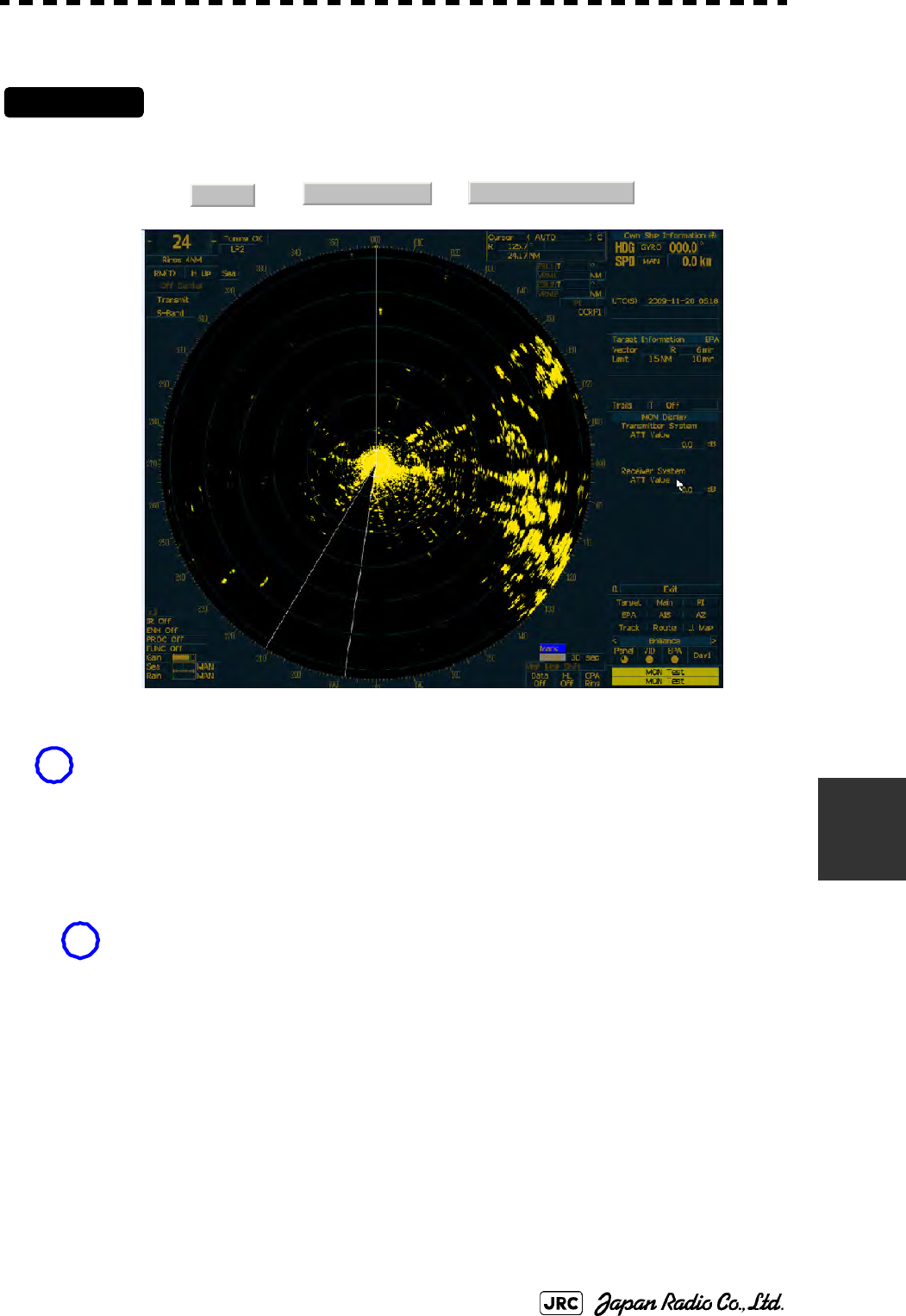
JMA-9172-SA Instruction Manual > 8.COUNTERMEASURE FOR TROUBLE ... > 8.3 PERFORMANCE CHECK
8-9
8
8.3.1.4 Check of the Performance Monitor (MON Display)
Procedures
1) Perform the following menu open procedure to open the “4. MON
Display menu”.
→→
2) Check the Transmitter System ATT Value and Receiver System
ATT Value.
Note: Features of Performance monitor of JMA-9172-SA radar
-The performance of the receiver and the transmitter is automatically calculated and indicated on
the radar screen like XX.X dB in two or three-digit value.
-Receiver check is performed within the PM sector in direction of stern of ship.
Therefore, even if the performance monitor is activated, the performance monitor pattern echo like
the performance monitor of the magnetron radar is not displayed at all.
As a result, the radar operator can clearly observe the echo around ships other than the direction of
the stern.
Main
9. Test Menu 4. MON Display
Blind sector appears on stern direction of ship to check receiver performance.
Range scale will be automatically changed to 24nm.
Sea and Rain dial will be automatically changed to minimum, and IR, ENH, PROC and FUNC
will be automatically changed to off. Push “EXIT” button, it will be returned to former state.
i
If Transmitter System ATT Value down > 7.0dB or Receiver System ATT Value down > 3.0dB,
Please consult the purchased distributor or nearest branch office (or our sales department).
i
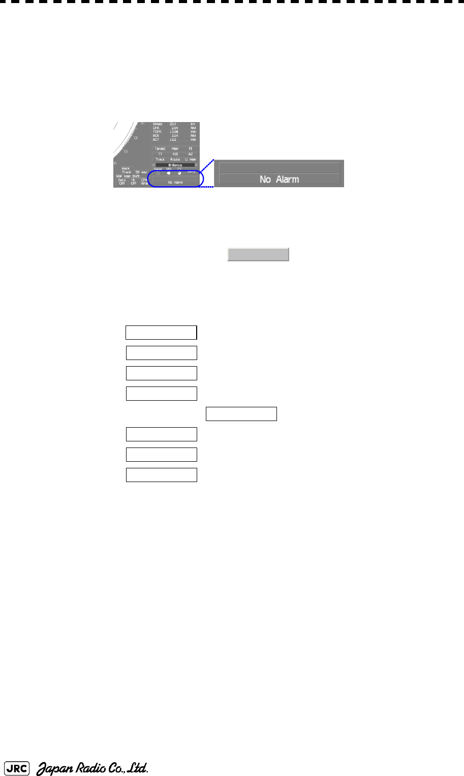
8-10
JMA-9172-SA Instruction Manual > 8.COUNTERMEASURE FOR TROUBLE ... > 8.3 PERFORMANCE CHECK
8.3.1.5 System Alarm Log display
Displays previously occurred system alarms with the dates and times when they
occurred.
The current alarm is displayed at the lower right of the radar display. For details,
refer to Section 9.1.1 "List of Alarms and other Indications".
The Alarm log display button (page2-31 Alarm) is clicked, in the same way as
that one.
To erase the alarm logs, press the button in the log display window.
8.3.1.6 System Information
Displays the current system information.
Processor software version information
Scanner software version information
System number
Total transmitting time
→
Total operating time (Total power-on time)
Total operating (power-on) time of the scanner unit
Total operating (power-on) time of the display unit
All Clear
Indicator
TXRX
System No.
TX Time
S-Band
Motor Time
TXRX Total Time
Total Time
JMA-9172-SA Instruction Manual > 8.COUNTERMEASURE FOR TROUBLE ... > 8.4 REPLACEMENT OF MAJOR PARTS
8-11
8
8.4 REPLACEMENT OF MAJOR PARTS
The system includes parts that need periodic replacement. The parts should be
replaced as scheduled. Use of parts over their service life can cause a system
failure.
• Turn off the main power source before replacing parts.
Otherwise, an electric shock or trouble may be caused.
• Two or more persons shall replace the liquid crystal
monitor. If only one person does this work, he may
drop the LCD, resulting in injury.
• Even after the main power source is turned off, some
high voltages remain for a while. Do not contact the
inverter circuit in the LCD with bare hands. Otherwise,
an electric shock may be caused.
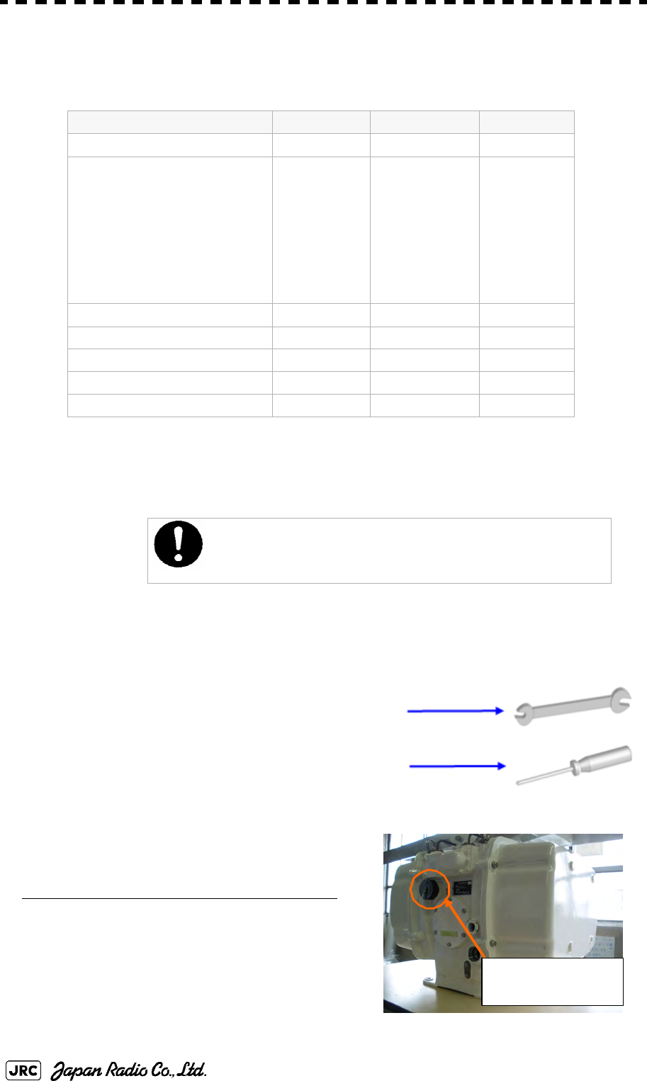
8-12
JMA-9172-SA Instruction Manual > 8.COUNTERMEASURE FOR TROUBLE ... > 8.4 REPLACEMENT OF MAJOR PARTS
8.4.1 Parts Required for Periodic Replacement
Here are parts required for periodic replacement
8.4.2 Replacement of Motor
8.4.2.1 Scanner Unit NKE-1532
[Required tools]
•
Wrenches (M5, M8, and M10)
•
A Phillips screwdriver (M2)
[Required procedure]
Removal of the pedestal cover
1) Turn off the safety switch of the scanner before
replacing the motor.
Part name Interval Part type Part code
1. Motor 10,000 hours MDBW10823*i
i. “*” means revision, such as A, B and so on.
ii. The φ92mm Fan is auxiliary use of the φ120mm Fan.
MDBW10823*i
2. Fan (Scanner Unit)
φ120mm (Radar process Unit)
φ92mm*ii (Radar process Unit)
φ60mm (Motor Driver)
φ60mm (Power Supply Unit)
90,000 hours
45,000 hours
45,000 hours
45,000 hours
H-7ZCRD1569*i
H-7ZCRD1570*i
H-7ZCRD1572*i
H-7ZCRD1574*i
7ZCRD1569*i
7ZCRD1570*i
7ZCRD1572*i
7ZCRD1574*i
3. LCD PANEL 50,000 hours 7WASR002*i7WASR002*i
4. Fan (Display Unit)
(Radar Process Circuit) 20,000 hours 109R0612S4D13 5BFAB00588
(Power Supply) 20,000 hours H-7BFRD0006*i7BFRD0006*i
5. Backup battery 5 years CR2032 5ZBCJ00012
Replacement of motor must be made by specialized service
personnel.
For details, refer to Service Manual.
Turn off the
safet
y
switch.
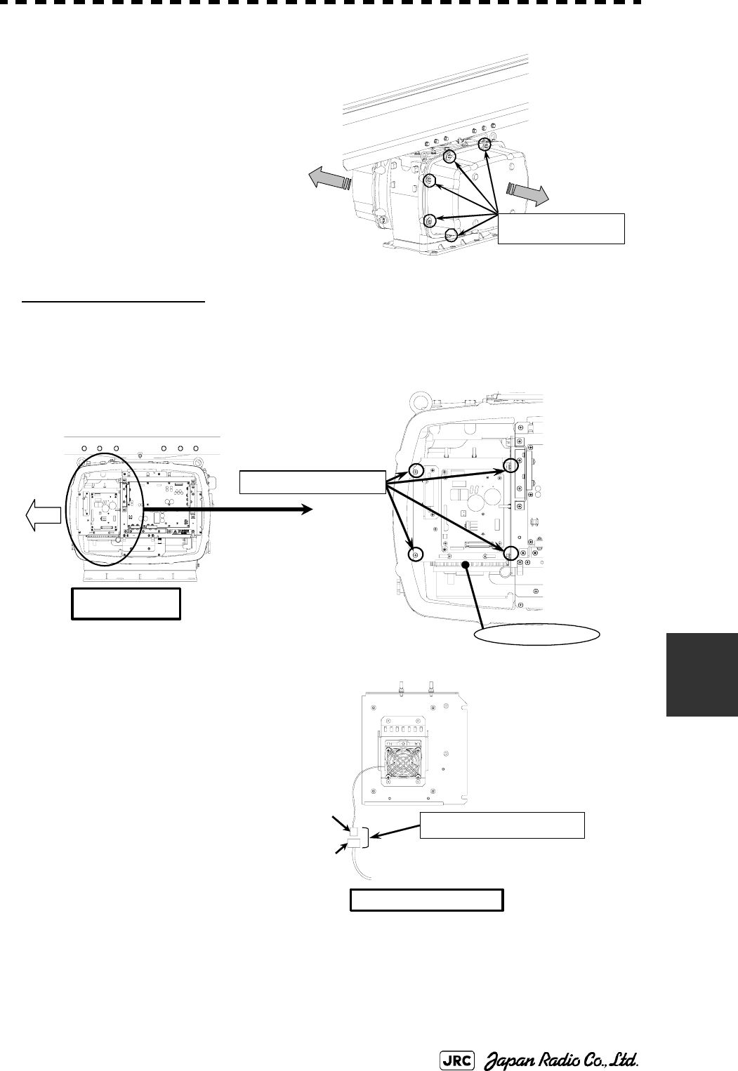
JMA-9172-SA Instruction Manual > 8.COUNTERMEASURE FOR TROUBLE ... > 8.4 REPLACEMENT OF MAJOR PARTS
8-13
8
2) Remove the pedestal cover of the
port side and the starboard side.
Make sure that there is no foreign
matter or dust adhered to the gasket
when you put the cover on.
Work of Port side
3) Loosen the hexagonal bolts. (four M5 bolts)
And, remove the motor driver unit.
4) Remove the relay connector
(P1901) connected to the motor
driver unit.
Remove the hexagonal bolts
( sixteen M8 bolts).
Bow
Portside
Motor driver unit
Loosen the four M5
Back of the motor driver unit
Remove the relay connector
P1901
J1901
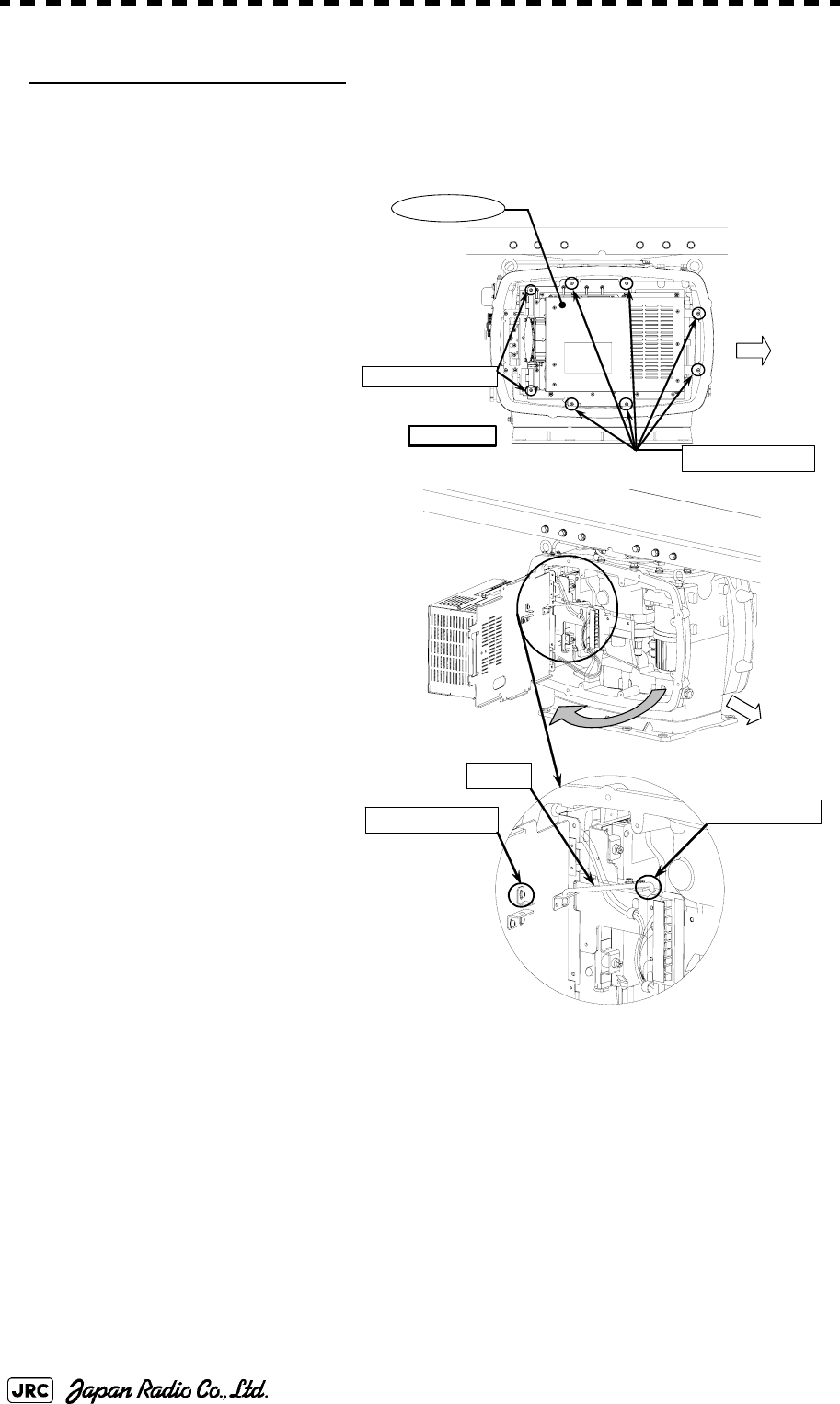
8-14
JMA-9172-SA Instruction Manual > 8.COUNTERMEASURE FOR TROUBLE ... > 8.4 REPLACEMENT OF MAJOR PARTS
Work of Starboard side
5) Remove the screws (two M4
screws) and the bolts (six M5
bolts) of the radar process unit.
6) Pull the radar process unit to the
open-position.
7) Loosen the M4 screw.
8) Hook the stopper in the insertion
hole.
Bow
Loosen the M4
Stopper
Insertion hole
Remove the six M5 bolts
Remove the two M4
Starboard side
Radar process unit
Bow
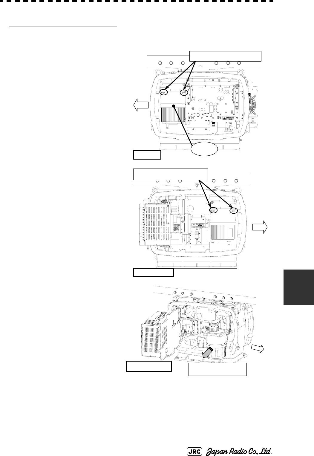
JMA-9172-SA Instruction Manual > 8.COUNTERMEASURE FOR TROUBLE ... > 8.4 REPLACEMENT OF MAJOR PARTS
8-15
8
4.Replacement of Motor
9) Remove the bolts (two M10 bolts) on
the portside of the motor.
10) Remove the bolts (two M10 bolts) on
the starboard side of the motor
11) Remove the motor.
Port side
Bow
Remove the two M10 bolts
Motor
Bow
Starboard side
Remove the two M10 bolts
Starboard side
Bow
Remove the motor
8-16
JMA-9172-SA Instruction Manual > 8.COUNTERMEASURE FOR TROUBLE ... > 8.4 REPLACEMENT OF MAJOR PARTS
12) Grease the gear wheel of the new motor.
13) Install the new motor in the scanner
unit and secure it using the
hexagonal bolts.
Tighten the bolts with the specified
torque (380 kgf-cm).
14) After replacing the motor, and
assemble the unit in the reverse order
of the disassembly procedure.
Do not forget to tighten the screws and bolts .
Do not forget to connect the cables.
[Operation check]
Follow the procedure below to check the operation after you have replaced the
motor.
1) Turn on the radar power supply. When the Countdown is completed, push the
“
TX /
STBY
”
button and check that the radar image appears without error. Check that you do
not listen any unusual sound starting, rotating, and stopping the motor.
2) Open the service engineer menu, and initialize the motor rotation time.
Grease the motor gear wheel
JMA-9172-SA Instruction Manual > 8.COUNTERMEASURE FOR TROUBLE ... > 8.4 REPLACEMENT OF MAJOR PARTS
8-17
8
8.4.3 Replacement of 23inch LCD
Do not touch the LCD screen directly with your fingers.
Do not touch the AR filter directly with your fingers.
Perform the replacement work on a soft cloth to avoid damage to the LCD screen and
other parts.
[Required tools]
•
A Phillips screwdriver for 4 mm screws
•
A Phillips screwdriver for 6 mm screws
[Disassembly]
1) Remove the tilt fixing handle (standalone type
only).
2) Tilt up the screen as much as you can
(standalone type only).
3) Remove the screws (M6) from the four
corners and displace the face cover.
Replacement of LCD monitor must be made by specialized
service personnel.
For details, refer to Service Manual.
Remove
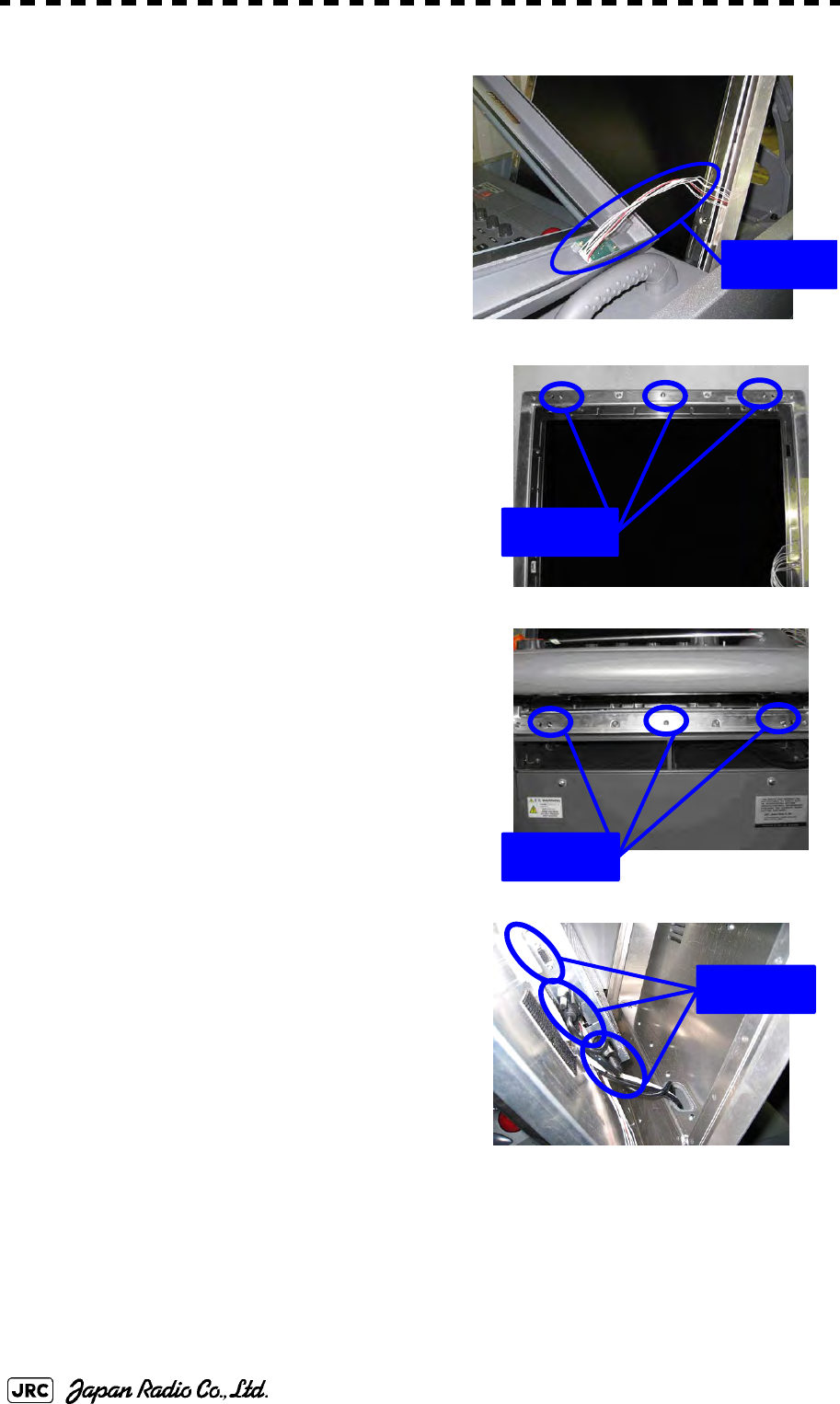
8-18
JMA-9172-SA Instruction Manual > 8.COUNTERMEASURE FOR TROUBLE ... > 8.4 REPLACEMENT OF MAJOR PARTS
4) LRemove the LCD operation circuit cables
and remove the face cover.
5) Remove six M4 screws.
6) Displace the module and remove the three
cables.
7) Remove the LCD module.
Remove
Remove
Remove
Remove
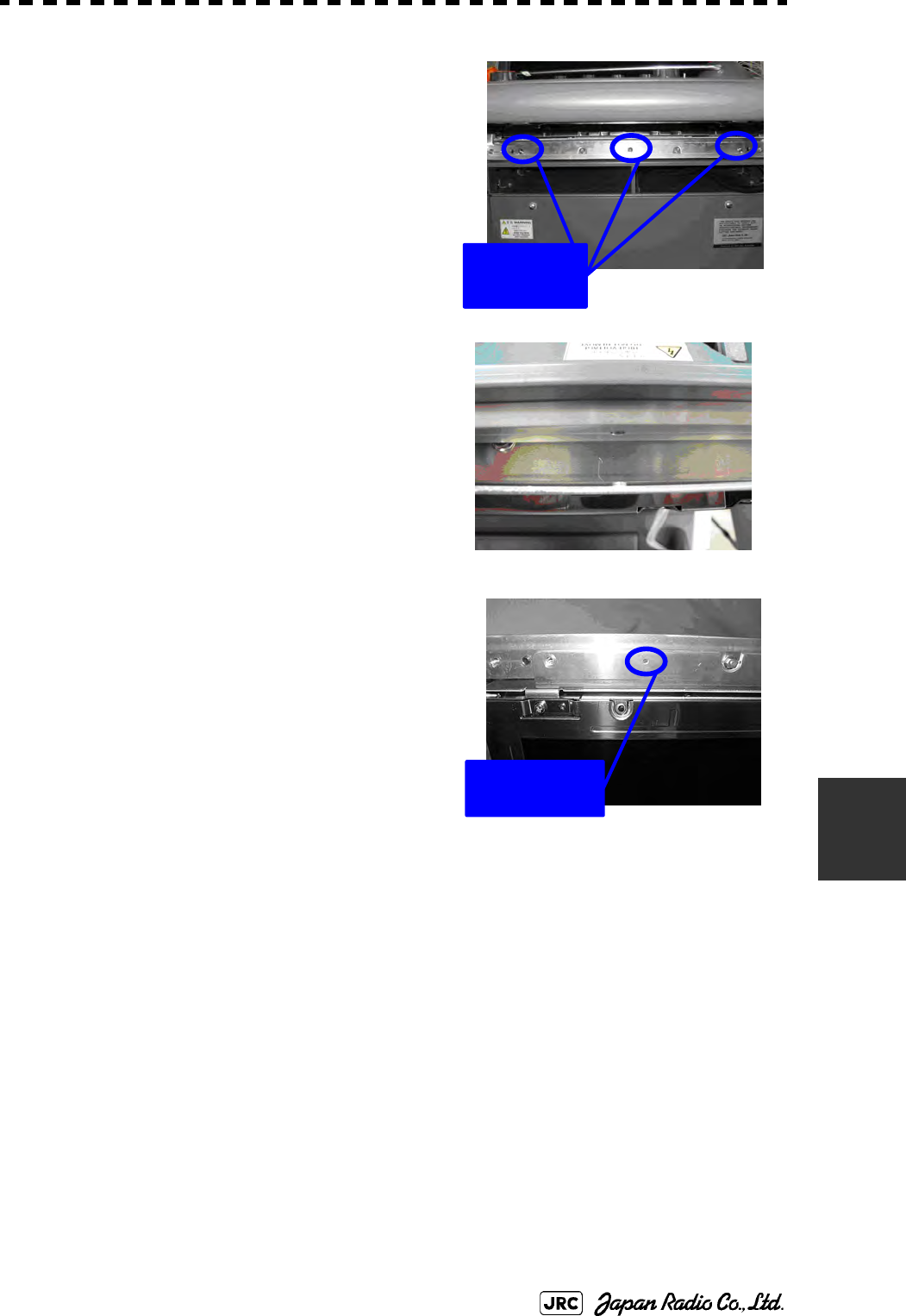
JMA-9172-SA Instruction Manual > 8.COUNTERMEASURE FOR TROUBLE ... > 8.4 REPLACEMENT OF MAJOR PARTS
8-19
8
[Assembly]
1) Tighten the lower three M4 screws halfway.
2) Connect the cables to the LCD module.
3) Align the module to the lower three screws
and insert it downward.
4) Check the positions of the two bosses and
ensure that appropriate space is maintained
under the LCD module. Tighten the six
screws evenly.
5) Connect the LCD operation circuit cables
and attach the face cover.
6) Tighten the screws at the four corners.
7) Attach the tilt fixing handle.
[Operation Check]
1) After completing the replacement
procedures, start the system to make sure that images are displayed properly.
2) Turn the brightness knob to make sure the brightness can be changed between the
minimum and the maximum levels.
Temporary
tightening
Positions of the
two bosses
8-20
JMA-9172-SA Instruction Manual > 8.COUNTERMEASURE FOR TROUBLE ... > 8.4 REPLACEMENT OF MAJOR PARTS
8.4.4 Replacement of Backup Battery
A coin-cell battery maintains radar system configuration, date, and time
information while power off condition. Radar system configuration is saving to
non-volatile memory at fixed intervals.
8.4.4.1 About the Battery Alarm
If is appeared at the lower-right of the display when start up the
radar system, the battery has not enough time left to live. We recommend to
replace the battery.
If is appeared at the lower-right of the display when start up the
radar system, the battery has no time left to live. There is a necessary to replace
the battery. In This condition, this radar system is restored configuration
information from flash memory and normal operation is available. However, you
turned of the radar system before saving to flash memory, the configuration
information is maybe lost. In this case, you must setup the configuration again.
8.4.4.2 How to Replacement of Backup Battery
[Required tools]
•
A flat tip screwdriver for 6 mm screws
•
A Phillips screwdriver for 4 mm screws
•
A flat tip nonconductive screwdriver for 3 mm screws
Replacement of backup battery must be made by specialized
service personnel.
For details, refer to Service Manual.
About disposal of used battery, refer to Section 10.2.
Battery Low
Battery Dead
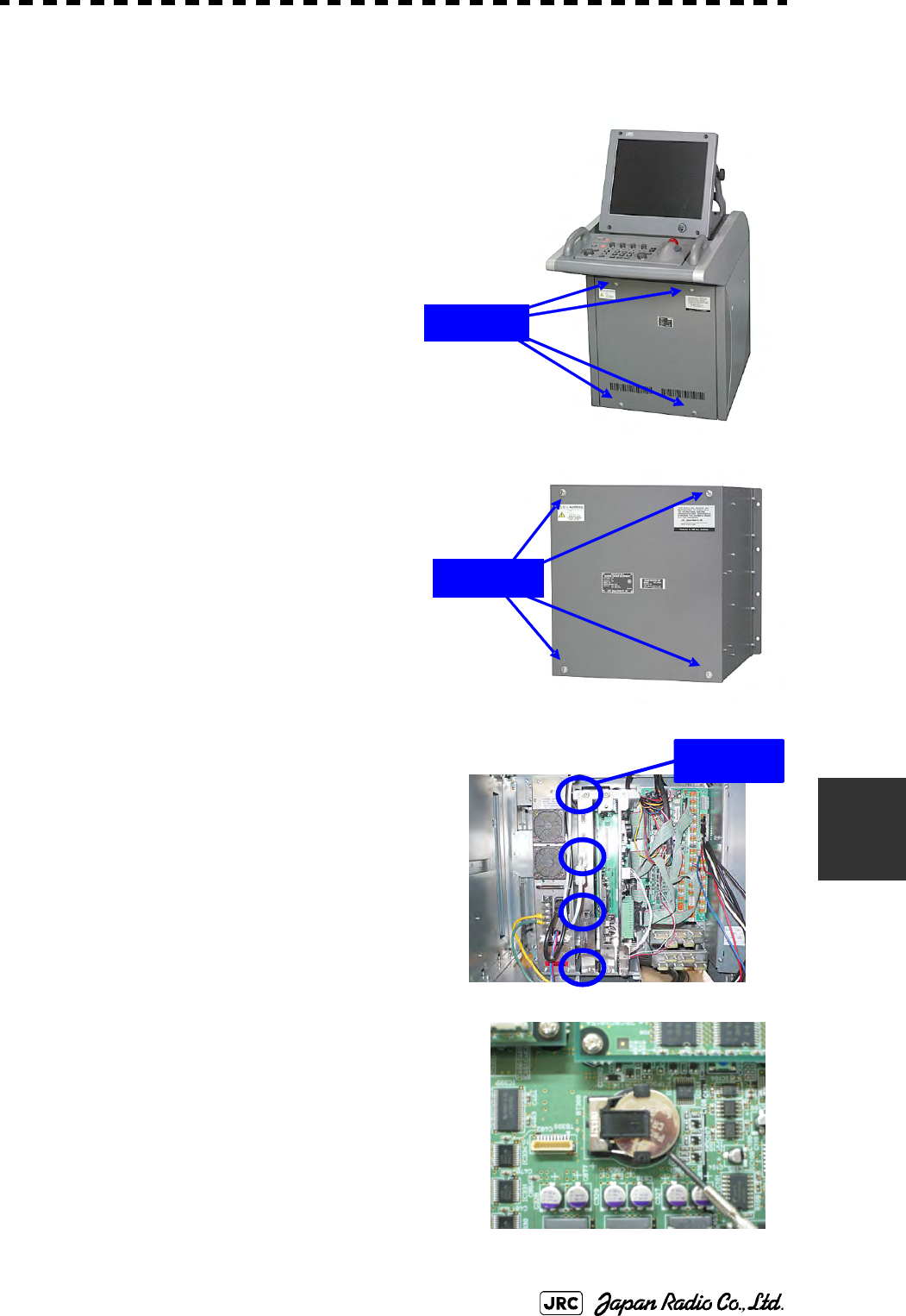
JMA-9172-SA Instruction Manual > 8.COUNTERMEASURE FOR TROUBLE ... > 8.4 REPLACEMENT OF MAJOR PARTS
8-21
8
[Disassembly]
1) Remove the four fixing screws to remove
the cover from the display unit (NCD-
9170).
(
A flat tip screwdriver for 6 mm screws
)
For standalone type NCD-9170
For desktop type: NDC-1478
2) Remove the cable connected to the radar
process circuit board.
The radar process circuit is the first board from
the left.
3) Remove the two fixing screws (M4).
4) Pull out the board to the front.
5) Insert the flat tip nonconductive screwdriver
for adjustment or some stick between the battery
and the battery holder and lift the battery up.
Remove
Remove
Remove
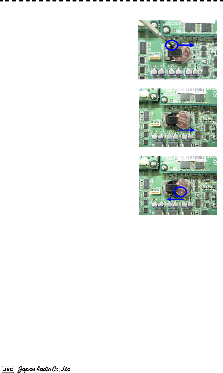
8-22
JMA-9172-SA Instruction Manual > 8.COUNTERMEASURE FOR TROUBLE ... > 8.4 REPLACEMENT OF MAJOR PARTS
6) Insert the flat tip nonconductive screwdriver for
adjustment or some stick to the location shown
in the figure below and slide the battery
sideways to remove the battery.
[Assembly]
1) Check the polarity of the battery. Make sure that
the battery's positive (+) side is facing up.
2) Slide the battery sideways into the battery
holder.
3) Make sure that the battery is inserted fully.
[Check Item]
1) Check that no error message comes up.
2) Check that the system starts up normally.
[Notes]
JMA-9172-SA Instruction Manual > 8.COUNTERMEASURE FOR TROUBLE ... > 8.4 REPLACEMENT OF MAJOR PARTS
8-23
8
If you installed the battery with the wrong polarity, remove the battery immediately and
do not use the same battery again.
During the procedures, do not put the battery on any circuit board or conductive item.
To dispose of a used battery, follow the instructions provided in Section 10.2 "DISPOSAL
OF USED BATTERIES".
To disassemble of a used battery, have to use non-conductive tool.

8-24
JMA-9172-SA Instruction Manual > 8.COUNTERMEASURE FOR TROUBLE ... > 8.4 REPLACEMENT OF MAJOR PARTS

TROUBLE SHOOTING AND AFTER-SALES SERVICE
9.1 FAULT FINDING .....................................................................................9-1
9.1.1 List of Alarms and other Indications .............................................9-1
9.1.2 Operation Checking ........................................................................9-6
9.1.3 Fuse Checking .................................................................................9-6
9.2 TROUBLE SHOOTING ...........................................................................9-7
9.2.1 Circuit Block to be Repaired ..........................................................9-7
9.3 AFTER-SALES SERVICE ......................................................................9-9
9.3.1 Keeping period of maintenance parts ...........................................9-9
9.3.2 When you Request for Repair ........................................................9-9
9.3.3 Recommended Maintenance ..........................................................9-9
SECTION 9
TROUBLE SHOOTING AND
AFTER-SALES SERVICE
JMA-9172-SA Instruction Manual > 9.TROUBLE SHOOTING AND AFTER-SALES SERVICE > 9.1 FAULT FINDING
9-1
9
9.1 FAULT FINDING
In case of semiconductor circuits, it is deemed that there are few cases in which
the used semiconductor devices have inferior quality or performance deterioration
except due to insufficient design or inspection or by other external and artificial
causes. In general, the relatively many causes are disconnection in a high-value
resistor due to moisture, a defective variable resistor and poor contact of a switch
or relay.
Some troubles are caused by defective parts, imperfect adjustment (such as tuning
adjustment) or insufficient service (such as poor cable contact). It will also be
effective to check and readjust these points.
9.1.1 List of Alarms and other Indications
If any of the following alarm occurs, the system displays the alarm message in red
in order to attract the attention of operator. Other messages are displayed with the
suitable color which is yellow or blue depending on the level of message
importance.
Alarm message is displayed in the lower right of the display. For more details
refer to page2-31 Alarm.
This section gives the list of alarms displayed by the system and other display
lists.
Alarm: Red •
Collision-related Alarm
•
Navigation Alarm
•
System Alarm
Warning: Yellow •
System Warning
Infomation: Blue •
Operation Information
Table9-1: Critical Alarm
Message Class Description ALR No.i
i. ALR No.: Unique alarm number in ALR sentence and ACK sentence
CPA/TCPA Alarm There is a dangerous target. 301

9-2
JMA-9172-SA Instruction Manual > 9.TROUBLE SHOOTING AND AFTER-SALES SERVICE > 9.1 FAULT FINDING
Table9-2: List of System Error Message
Message Class Description ALR No.i
Autopilot (Data) Alarm Autopilot: No communication or data error. 101
Current (Data) Alarm Tidal current: No communication or data error. 119
Date (Data) Alarm Date data: No communication or data error. 112
Datum (Data) Alarm DTM: No communication or data error. 122
Depth (Data) Alarm Water depth: No communication or data error. 115
Fan (LCD) Alarm LCD monitor: Fan error. 955
Fan (Power) Alarm Power Supply: Fan error. 953
Fan (PROC) Alarm RADAR Process Unit Interconnection: Fan error. 951
GPS (Status) Alarm GPS status error. 103
GYRO I/F (Data) Alarm GYRO I/F: No communication or checksum error. 324
GYRO I/F (GYRO) Alarm GYRO I/F: GYRO error detected. 110
GYRO I/F (Log) Alarm GYRO I/F: Log error detected. 111
Heading (Data) Alarm Heading data: No communication or data error. 113
Keyboard (Data) Alarm Operation unit: Communication error or checksum
error. 325
Keyboard2 (Data) Alarm Second operation unit: Communication error or
checksum error. 325
Out of Bounds Alarm Own ship's latitude is over 85°N or 85°S. 123
Position (Data) Alarm Latitude / longitude data: No communication or data
error. 102
PROC (AZI) Alarm Process unit: AZI error. 305
PROC (HL) Alarm Process unit: HL error. 306
PROC (Interrupt) Alarm Process unit: Interrupt error. 962
PROC (Trigger) Alarm Process unit: Trigger error. 304
PROC (Video) Alarm Process unit: VIDEO error. 303
ROT (Data) Alarm Rate of Turn: No communication or data error. 120
RSA (Data) Alarm Rudder Sensor Angle: No communication or data
error. 121
Speed (2AXG) Alarm 2-axis log (speed over ground): No communication
or data error. 114
Speed (2AXW) Alarm 2-axis log (speed over water): No communication or
data error. 114
Speed (GPS) Alarm GPS speed: No communication or data error. 114
Speed (Log) Alarm 1-axis log: No communication or data error. 114
SRB (Data) Alarm SRB: No communication or data error. 960
TEMP. (Data) Alarm Water temperature: No communication or data error. 117
TXRX (AZI) Alarm Scanner: BP error. 311
TXRX (Data) Alarm Scanner: No communication, communication
mismatched, checksum error, or collision. 326
TXRX (Fan 1) Alarm Scanner: FAN 1 error.
TXRX (Fan 2) Alarm Scanner: FAN 2 error.
TXRX (Fan 3) Alarm Scanner: FAN 3 error.
TXRX (HL) Alarm Scanner: HL error.
TXRX (Lo PLL) Alarm Scanner: Local PLL error.
TXRX (PROC) Alarm Radar Processor error
TXRX (PS) Alarm Power Supply error
JMA-9172-SA Instruction Manual > 9.TROUBLE SHOOTING AND AFTER-SALES SERVICE > 9.1 FAULT FINDING
9-3
9
TXRX (Reverse) Alarm Scanner: Reverse rotation.
TXRX (SSW Off) Alarm Scanner: Safety switch OFF.
TXRX (Trigger) Alarm Scanner: TRIGGER error..
TXRX (Video) Alarm Scanner: VIDEO error.
Wind (Data) Alarm Wind direction/velocity: No communication or data
error. 118
i. ALR No.: Unique alarm number in ALR sentence and ACK sentence
Table9-3: List of Notification
Message Class Description ALR No.i
i. ALR No.: Unique alarm number in ALR sentence and ACK sentence
CCRP Changed INFO CCRP is automatically changed.
Copying INFO Displayed-image is capturing to file.
POSN Reset INFO Change the latitude and longitude sentence.
Set GYRO INFO Requires setting of true bearing.
TM Reset INFO Resetting TM in a short time.
Table9-4: List of Target Tracking Alarms and AIS Function Alarms
Message Class Description ALR No.i
i. ALR No.: Unique alarm number in ALR sentence and ACK sentence
AIS (Data) Alarm AIS: No communication or communication error. 116
AIS 95% Capacity INFO Over 95% of the maximum number of AIS targets.
AIS ACT 95%
Capacity INFO Over 95% of the maximum number of AIS targets to
be activated.
AIS ACT MAX INFO Maximum number of AIS targets to be activated.
AIS Alarm ***ii Alarm AIS alarm (Up to 10 alarm messages can be
displayed.).
AIS Max Target INFO Maximum number of AIS targets.
AIS PROC (Data) Alarm AIS processing circuit: No communication or
communication error. 328
CPA/TCPA Alarm There is a dangerous target. 301
Lost Alarm Failure in tracking the target that has been under
tracking.
Failure in receiving AIS target data for a specified
time.
New Target Alarm Acquisition or activation of a target in the automatic
acquisition / activation zone. 302
REF Target Alarm Decrease in the reference target accuracy.
Trial Warning There is a dangerous target, when trial maneuver is
active.
TT (Boot) Alarm Target tracking unit start failure. 344
TT (Data) Alarm The target tracking unit is malfunctioning. 323
TT 95% Capacity INFO Over 95% of the maximum number of targets to be
tracked.
TT MAX Target INFO The maximum number of targets is under acquisition.
Table9-2: List of System Error Message
Message Class Description ALR No.i
9-4
JMA-9172-SA Instruction Manual > 9.TROUBLE SHOOTING AND AFTER-SALES SERVICE > 9.1 FAULT FINDING
ii. *** is a 3-digit number which is Local Alarm No in the ALR sentence.
Table9-5: List of Route Messages and Warnings
Message Class Description ALR No.i
i. ALR No.: Unique alarm number in ALR sentence and ACK sentence
Approach Alarm Approach the route.
Arrival Alarm Arrive at way point.
Break Off(WPT) Alarm Out of the way point.
Cross Track Error Alarm Go off the route.
Table9-6: List of Operational Alarm Messages and Warnings
Message Class Description ALR No.i
i. ALR No.: Unique alarm number in ALR sentence and ACK sentence
Can't Transmit INFO Tried to transmit within 5 second after standby or
when the transmitter-receiver has any trouble.
Card Full INFO Card: Run out of free space.
Copy Failed INFO Card: Copy failure.
Delete Failed INFO Card: Deletion failure.
Format Card INFO Card: Unformatted card.
Format Failed INFO Card: Format failure.
Invalid Card INFO Card: Invalid card.
Invalid Connection INFO The operator set performance monitor to on without
selecting straight.
Invalid Data INFO Tried to enter any data beyond its range.
Invalid Range INFO TM selection due to TM-disabled range (96 nm).
Zooming in a ZOOM-disabled range (0.125 nm).
MAX Point INFO Tried to enter navigation information beyond the
specified.
No Card INFO Card not detected yet.
No Heading Data INFO Target tracking operation or TM selection when
bearing data is invalid.
No Object INFO No object at the cursor-specified position.
No Position Data INFO Mark or line input when the latitude and longitude is
invalid.
Not Allowed INFO General operation error.
Out of Range INFO Out of target acquisition range.
Read Failed INFO Card: Read failure.
Slave Mode INFO Operation of a menu for the scanner unit when the
slave mode is active.
Write Failed INFO Card: Write failure.
JMA-9172-SA Instruction Manual > 9.TROUBLE SHOOTING AND AFTER-SALES SERVICE > 9.1 FAULT FINDING
9-5
9
Note: Interswitch is un-available for evaluation model.
Table9-7: List of Conditions Messages
Message Class Description ALR No.i
i. ALR No.: Unique alarm number in ALR sentence and ACK sentence
Battery Dead Warning The battery is dead.
Battery Low Warning battery is weakening.
GPS (HDOP) Warning The HDOP level is increased (Decrease in the GPS
accuracy.).
MON Test Warning Performance monitor is active.
Scanner Rotating Warning The scanner is rotating (When transmitter is standby
state.).
Table9-8: List of Interswitch Alarms and Messages
Message Class Description ALR No.i
i. ALR No.: Unique alarm number in ALR sentence and ACK sentence
Connection
Masked INFO Inhibition of control / connection is set.
ISW (Data) Alarm No communication, data mismatched, or checksum error. 327
ISW Busy INFO Access to the ISW menu was made during interswitching.
ISW Complete INFO The switchover of the Interswitch ended normally.
ISW Error INFO The interswitch is disabled.
ISW Standby INFO The Interswitch recovered normally.
ISW Straight INFO The interswitch is forced to change the connection
into straight.
ISW Time Out INFO Failed in switching.
Master Range CHG INFO The range of the own display unit has changed due
to change in the range of the master display unit.
Master Standby INFO The master display unit does not transmit any
signals.
Pattern CHG Failed INFO Connection change failed.
TXRX Standby INFO The scanner unit is in the standby mode.
Update ISW
Software INFO Tried to enter new TXRX function, when interswitch
software used old version.
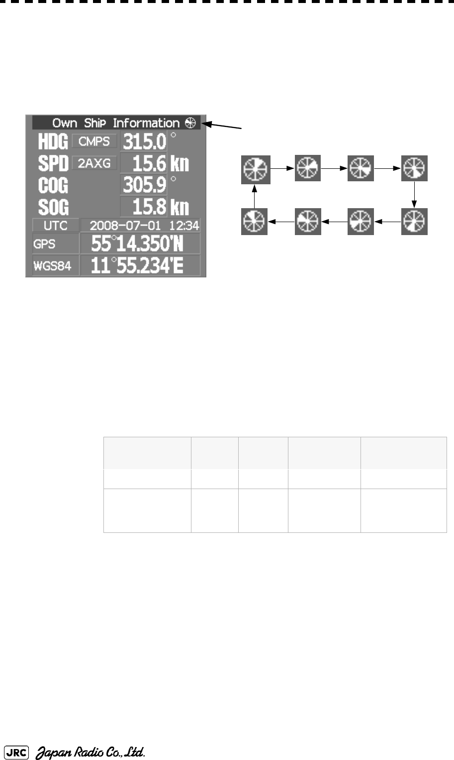
9-6
JMA-9172-SA Instruction Manual > 9.TROUBLE SHOOTING AND AFTER-SALES SERVICE > 9.1 FAULT FINDING
9.1.2 Operation Checking
When the system is operating, the operation status (located at the upper right of
the screen) is changing pictures.
If picture freeze occurred, turn off the system and restart the system.
9.1.3 Fuse Checking
Melted fuses are caused by any clear cause. When a fuse is replaced, it is
necessary to check the related circuits even if there is no trouble. In checking, note
that there is some dispersion in the fusing characteristics. Table 9-8 shows a list of
fuses used in the equipment.
Table9-9: Fuse List
Location Parts# Current
Rating Protection
Circuit Type
AC/DC Converter F501 10A Motor ST6-10AN1
GYRO Interface
circuit F1~F4 0.5A GYRO
Interface
circuit
MF60NR250V0.5
Operation Status
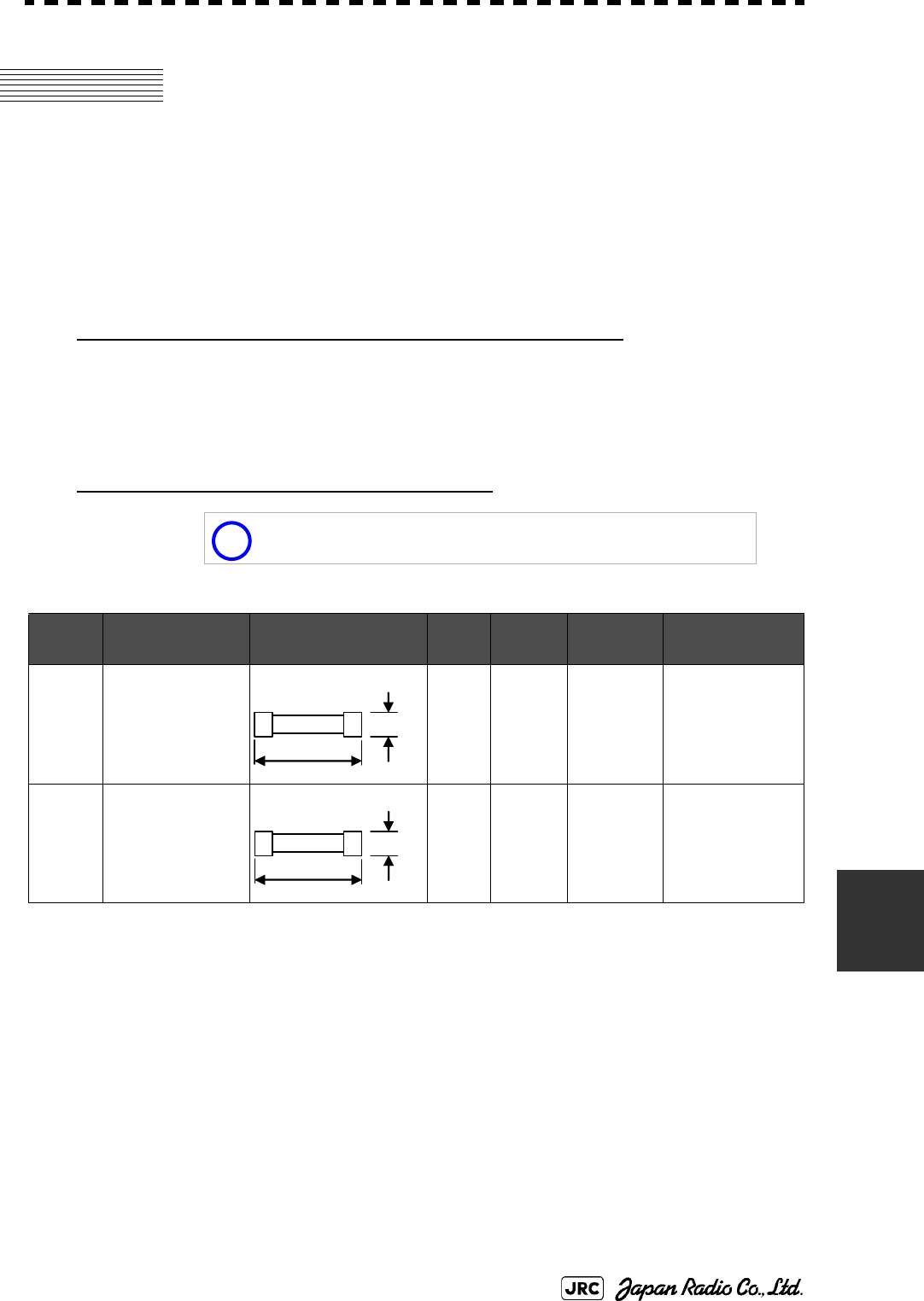
JMA-9172-SA Instruction Manual > 9.TROUBLE SHOOTING AND AFTER-SALES SERVICE > 9.2 TROUBLE SHOOTING
9-7
9
9.2 TROUBLE SHOOTING
As this radar equipment includes complicated circuits, it is necessary to request a
specialist engineer for repair or instructions for remedy if any circuit is defective.
There are also troubles by the following causes, which should be referred to in
checking or repair work.
1 Poor Contact in Terminal Board of Inter-Unit Cables
a. Poor contact in terminal board
b. The cable end is not fully connected, that it, contacted with earthed another
terminal.
c. Disconnected cable wire
2 Poor Contact of Connector within Unit
9.2.1 Circuit Block to be Repaired
This radar equipment is provided with Table 9-10 standard
spares.
Table9-10: 7ZXRD0025
Name Type/Code Shape (mm) In
use Spare Parts # Location
Fuse MF60NR250V0.5
(5ZFGD00006)
412 F1~F4 GYRO Interface
Circuit
CMJ-462E
Fuse ST6-10AN1
(5ZFCA00053)
13 F501 AC/DC Converter
NBA-5135
i
30
Φ6.4
31.8
Φ6.35

9-8
JMA-9172-SA Instruction Manual > 9.TROUBLE SHOOTING AND AFTER-SALES SERVICE > 9.2 TROUBLE SHOOTING
Table9-11: Circuit Block to be Repaired (JMA-9172-SA)
Location Circuit Block Type Remarks
SCANNER UNIT MOTOR H-7BDRD0049*i
i. “*” means revision, such as A, B and so on.
DC brushless motor
SCANNER UNIT AC220V MOTOR DRIVER CBD-2010
SCANNER UNIT AC100V MOTOR DRIVER CBD-2011
SCANNER UNIT BRAKE CIRCUIT CFA-1255
SCANNER UNIT BRAKE CIRCUIT A CFA-1261
SCANNER UNIT BRAKE CIRCUIT B CFA-1262
SCANNER UNIT BRAKE CONTROL CIRCUIT CCB-1655
SCANNER UNIT ENCODER CHT-1071
SCANNER UNIT IF INPUT/OUTPUT CIRCUIT CHA-396
SCANNER UNIT INTERFACE CIRCUIT CMH-2246
SCANNER UNIT PERFOMANCE MONITOR CAY-71
SCANNER UNIT POWER SUPPLY CIRCUIT CBD-1798
SCANNER UNIT RADAR PROCESS CIRCUIT CDC-1349
SCANNER UNIT RELAY FILTER CIRCUIT CSC-1656
RADAR
PROCESS UNIT RADAR PROCESS CIRCUIT MPBC44213* CDC-1362 with mounting bracket,
CDC-1363 and CDC-1186D
RADAR
PROCESS UNIT RADAR PROCESS CIRCUIT MDLW11900* CDC-1362 with mounting bracket
RADAR
PROCESS UNIT AIS PROCESS CIRCUIT CDC-1363
RADAR
PROCESS UNIT ARPA PROCESS CIRCUIT CDC-1364
RADAR
PROCESS UNIT GYRO INTERFACE CIRCUIT CMJ-523
RADAR
PROCESS UNIT TERMINAL BOARD CQD-2176
RADAR
PROCESS UNIT MOTHER BOARD CQC-1230
RADAR
PROCESS UNIT FAN (RPU) 109R0612S4D13
RADAR
PROCESS UNIT POWER SUPPLY CBD-1861
RADAR
PROCESS UNIT FAN (PSU) H-7BFRD0006*
OPERATION
UNIT OPERATION CIRCUIT A CCK-1005
OPERATION
UNIT OPERATION CIRCUIT B CCK-1006
OPERATION
UNIT OPERATION CIRCUIT D CCK-1007
OPERATION
UNIT TRACKBALL CCK-1013
MONITOR UNIT BEZEL KIT MPXP34376* Radar bezel kit
MONITOR UNIT 23 inch LCD CML-799 23.1-inch LCD PANEL
MONITOR UNIT LCD OPERATION CIRCUIT CCK-1004

JMA-9172-SA Instruction Manual > 9.TROUBLE SHOOTING AND AFTER-SALES SERVICE > 9.3 AFTER-SALES SERVICE
9-9
9
9.3 AFTER-SALES SERVICE
9.3.1 Keeping period of maintenance parts
Keeping period of maintenance parts is ten years from the production is
discontinued.
9.3.2 When you Request for Repair
If you suppose the product may be out of order, read the description in Section 9
carefully and check the suspected point again.
If it is still out of order, you are recommended to stop operation of the equipment
and consult with the dealer from whom you purchased the product, or our branch
office in your country or district, the sales department in our main office in Tokyo.
Repair within the Warranty Period
If any failure occurs in the product during its normal operation in accordance with
the instruction manual, the dealer or JRC will repair free of charge. In case that
any failure is caused due to misuse, faulty operation, negligence or force major
such as natural disaster and fire, the product will be repaired with charges.
Repair after the Warranty Period
If any defective function of the product is recoverable by repair, the repair of it
will be made at your own charge upon your request.
Necessary Information for Repair
•Product name, model, manufacturing date and serial number
•Trouble conditions (as detailed as possible. Refer to "Radar Failure Check
List" on page 9-10
•Name of company/organization, address and telephone number
9.3.3 Recommended Maintenance
The performance of the product may deteriorate due to the secular change of the
parts used in it, though such deterioration depends upon the conditions of
operation. So checkup and maintenance is recommendable for the product in
addition to your daily care.
For maintenance, consult with the near-by dealer or our sales department.Such
maintenance will be made with charges.
For further details of after-sale service, contact the JRC Offices.
9-10
JMA-9172-SA Instruction Manual > 9.TROUBLE SHOOTING AND AFTER-SALES SERVICE > 9.3 AFTER-SALES SERVICE
Radar Failure Check List
Check the following items in the order of the number, and check the applicable
answer between YES or NO.
If the item cannot be determined as YES or NO, explain in detail in the item (16),
others.
iWhen placing an order for repair of the product, it is requested that you could
confirm the check items and fill the results and sent the sheet to our contact.
If there is any unclear items, contact the ship on which the product is
installed, and give the correct information on the product.
Ship name: Phone: Fax:
iRadar general model name:JMA-
i. Write the full model name correctly
iSerial No. :
No. Check Item Result
(1) Power can be turned on. (The lamp on the Operation unit is lit) YES NO
(2)i
i. If result is NO, then check the fuse. (Refer to Section 9.1.2 "Operation Checking" and Section 9.2 "TROUBLE
SHOOTING")
A few minutes after powering-on, it will become standby status. YES NO
(3)iWhen powering-on (or TX ON), LCD monitor something is lit. YES NO
(4)i,ii YES NO
(5)ii Fixed marker is displayed. YES NO
(6)ii VRM is displayed. YES NO
(7)ii While noise is displayed while set at SEA and RAIN minimum, GAIN
maximum, IR-OFF and range 48 NM. YES NO
(8)ii Target reflection echo is displayed. YES NO
(9)ii Sensitivity of reflection echo is normal. YES NO
(10)ii EBL is displayed. YES NO
(11)ii Cursor mark moves. YES NO
(12)ii,ii
ii. Check these items at transmission.
iii. Functions mentioned in the items (12), (13) and (15) may be optional, answer is not necessary.
GYRO course can be set and normally displayed. YES NO
(13)ii,iii LOG speed can be normally displayed. YES NO
(14)ii Target tracking function works normally. YES NO
(15)ii,iii If equipped with an interswitch, when switching from the straight mode (II) to
(X), the failures (items marked NO) in the above (1) to (14), are switched over
to the other unit.
YES NO
(16)Others (Error message, etc. )

DISPOSAL
10.1 DISPOSAL OF THE UNIT ....................................................................10-1
10.2 DISPOSAL OF USED BATTERIES .....................................................10-1
10.3 ABOUT THE CHINA ROHS .................................................................10-2
SECTION 10
DISPOSAL
JMA-9172-SA Instruction Manual > 10.DISPOSAL > 10.1 DISPOSAL OF THE UNIT
10-1
10
10.1 DISPOSAL OF THE UNIT
When disposing of this unit, be sure to follow the local laws and regulations for
the place of disposal.
10.2 DISPOSAL OF USED BATTERIES
In this unit, Lithium batteries are used for the following parts:
Radar Processing circuit (CDC-1362): BT300 (Maxell: CR2032)
•Do not store used lithium batteries. Dispose of them in accordance with
regulations of local government.
•When disposing of used lithium batteries be sure to insulate the batteries by
taping the terminals. For disposal of batteries, be sure to follow the local
laws and regulations. For detail, consult with the dealer you purchased the
product our business office, or local government.
When disposing of used lithium batteries, be sure to
insulate the batteries by taping the terminals.
Otherwise, heat generation, explosion or a fire may
occur.
+ -
+ -
10-2
JMA-9172-SA Instruction Manual > 10.DISPOSAL > 10.3 ABOUT THE CHINA ROHS
10.3 ABOUT THE CHINA ROHS
形式名(Type): JMA-9100 Series, JMA-7100Series 名称(Name): RADAR
铅 汞 镉 六价铬 多溴联苯 多溴二苯醚
(Pb) (Hg) (Cd) (Cr6+) (PBB) (PBDE)
雷达天线单元
(Scanner Unit)
××○×××
收发信单元
(Transmitter-receiver Unit)
××××××
主船内装置 (Inboard Unit)
・显示装置 (Display Unit)
・键盘装置 (OperationUnit)
・信号处理装置
(RADAR Process Unit)
××××××
外部设备 (Peripherals)
・选择 (Options)
・电线类 (Cables)
・手册 (Documennts)
××××××
有毒有害物质或元素的名称及含量
(Names & Content of toxic and hazardous substances or elements)
(Toxic and Hazardous Substances and Elements)
×:表示该有毒有害物质至少在该部件的某一均质材料中的含量超出SJ/T11363-2006 标准规定的限量要求。
(Indicates that this toxic or hazardous substance contained in at least one of the homogeneous materials
used for this part is above the limit requirement in SJ/T 11363-2006.)
○:表示该有毒有害物质在该部件所有均质材料中的含量均在SJ/T11306-2006 标准规定的限量要求以下。
(Indicates that this toxic, or hazardous substance contained in all of the homogeneous materials for this
part is below the requirement in SJ/T11363-2006.)
部件名称
(Part name)
有毒有害物质或元素

SPECIFICATION
11.1 JMA-9172-SA TYPE RADAR ...............................................................11-1
11.2 SCANNER UNIT (NKE-1139) ...............................................................11-2
11.3 DISPLAY UNIT (NCD-4990) .................................................................11-3
11.4 Target Tracking Function ...................................................................11-6
11.5 AIS FUNCTION .....................................................................................11-7
SECTION 11
SPECIFICATION

JMA-9172-SA Instruction Manual > 11.SPECIFICATION > 11.1 JMA-9172-SA TYPE RADAR
11 -1
11
11.1 JMA-9172-SA TYPE RADAR
GENERAL SPECIFICATION
Class of emission P0N, Q0N
Display Color Raster Scan
Screen 23.1inch LCD (Effective diameter of Radar: more than 320mm)
Range Scale 0.125, 0.25, 0.5, 0.75, 1.5, 3, 6, 12, 24, 48, 96NM
Range Resolution less than 30m
Minimum Detection Range less than 40m
Bearing Accuracy less than 1°
Bearing Indication Relative motion mode : N-UP, C-UP and H-UP
True motion mode : N-UP and C-UP
Ambient Condition Temperature
SCANNER UNIT -25 to +55℃ (Storage -25 to +70℃)
Other Unit -15 to +55℃
Relative humidity 93% at +40℃
Vibration 2 to 13.2Hz Amplitude +/-1mm +/-10%
13.2 to 100Hz Acceleration 7m/s2
Power Supply Input AC100 to 115V, 50/60Hz, 1φ or
AC220 to 240V, 50/60Hz, 1φ
Power Consumption Approx.600VA typical
Approx. 2200VA at Maximum wind speed
PS Voltage Fluctuation +/-10% (at the maximum cable length)
Pre Heating Time Within10 sec
From STBY to TX Within 5 sec.
SCANNER UNIT (NKE-1532)
See 11.2
DISPLAY UNIT (NCD-9170)
See 11.3
OPTION
Scanner with Deicing Heater NKE-1532-D (Only heater collar)
DISPLAY UNIT (Desktop type) NCD-9170T
Maximum Cable Length
SCANNER UNIT to
TRANSMITTER RECEIVER UNIT 65m
SAFE DISTANCE FOR STANDARD COMPASS
SCANNER UNIT 5.1m
DISPLAY UNIT 4.0m
11 -2
JMA-9172-SA Instruction Manual > 11.SPECIFICATION > 11.2 SCANNER UNIT (NKE-1532)
11.2 SCANNER UNIT (NKE-1532)
*i: PRF setting is "Normal" : 1860Hz
PRF setting is "High Power" : 2280Hz Refer to Appendix 3.8.3.2
SCANNER UNIT NKE-1130
Dimension Height 791 x Swing Circle 4000 (mm)
Mass Approx.170kg
Polarization Horizontal
Directional Characteristics Horizontal beam width
Vertical beam width
Side lobe Level
: 1.9°
: 25°
: below -26dB (within +/-10°)
: below -30dB (outside +/-10°)
Revolution Approx.24rpm
Power Supply for Motor AC100 - 115V、50/60Hz、1φ or
AC220 - 240V、50/60Hz、1φ
Maximum Wind Velocity 51.5m/s (100knots)
Transmitting Frequency P0N(3040MHz), Q0N(3060MHz±4MHz)
Transmitting Power 300W (+25/-50%)
Transmitter Solid State Power Amplifier
TX Pulse width (1st) /
TX Pulse width,
Frequency Deviation Width (2nd)
/ Repetition Frequency
SP1:0.07μs / 4.6μs, 8MHz / 1860Hz or 2280Hz *i
MP1:0.14μs / 9.1μs, 8MHz / 1860Hz or 2280Hz *i
MP2:0.29μs / 9.1μs, 8MHz / 1860Hz or 2280Hz *i
LP1:0.57μs / 9.1μs, 8MHz / 1280Hz
LP2:1.14μs / 18.3μs, 8MHz / 640Hz
0.125、0.25、0.5NM :SP1
0.75NM :SP1/MP1
1.5NM :SP1/MP1/MP2
3NM :SP1/MP1/MP2/LP1/LP2
6NM :MP1/MP2/LP1/LP2
12NM :MP2/LP1/LP2
24NM :LP1/LP2
48NM :LP2
96NM :LP2
Duplexer Circulator + Diode Limiter
Front End Module Built-in
Intermediate Frequency Amplifier Intermediate Frequency
Band Width
Gain
Amplifying Characteristics
: 63MHz
: 30MHz
: more than 50dB
: Linear Amplifier
Overall Noise Figure within 4.0dB ( Typical)

JMA-9172-SA Instruction Manual > 11.SPECIFICATION > 11.3 DISPLAY UNIT (NCD-9170)
11 -3
11
11.3 DISPLAY UNIT (NCD-9170)
DISPLAY UNIT NCD-9170
Dimension Width 700 x Depth 850 x Height 1100 (mm)
Structure Self-Standing, Drip Proof
Mass Approx.130kg
Screen 23.1inch Color LCD (Effective Diameter, more than 320mm)
Viewing Distance 1m from the center of Display
Range Scale 0.125, 0.25, 0.5, 0.75, 1.5, 3, 6, 12, 24, 48, 96NM
Range Marker 0.025, 0.05, 0.1, 0.25, 0.25, 0.5, 1, 2, 4, 8, 16NM
Range Accuracyr Less than 1% of the Range Scale in use, or 30m whichever is larger
Variable Range Marker 2 (VRM1/VRM2)
VRM Scale 0.000 to 100.0nm, Numerical Indication in 4 digits
Bearing Scale 360° in 1° step
Off Center Within 66% of Radius, except 96nm range
Trackball Cursor Built-in (Target Range, Relative/True bearing Presentation)
Electronic Bearing Lines 2 (EBL1/EBL2) (on Center/Floating)
EBLBearing Indication 000.0° to 359.9°Numerical Indication in 4 digits
Marking Function Electronic Mark (Maximum 20 points)
Heading Line Indication Electronic
True Motion Unit Built in (0.25, 0.5, 0.75, 1.5, 3, 6, 12, 24 and 48nm)
Anti Sea Clutter (SEA) Manual/AUTO
Anti Rain Clutter (SEA) Manual/AUTO
Display mode North-up / Head-up / Course-up
Trails Indication Off/0.25/0.5/1/3/6/10/15/30/60min
Video Process (PROC) Built in (Scan correlation / Remain)
Interference Rejection (IR) Built in ( Off / Low / Middle / High)
Auto-acquisition Zone (AZ) Sector (2)
User MapiBuilt in, Mark and Line (20,000 points)
Self diagnostic function Built in
Own Ship's Track IndicationiBuilt in
Parallel Index Line (PI) Built in
AIS Indication Built in Display
Activate 300
100
Association function:Built in
Interfacing Slave Display (TRG, VD, BP, BZ)
GPS IEC61162-1(NMEA0183)
LOG
GYRO
AIS IEC61162-2
Radar Buoy
External Alarm output
Receivable Signalii
11 -4
JMA-9172-SA Instruction Manual > 11.SPECIFICATION > 11.3 DISPLAY UNIT (NCD-9170)
Receive capability
Port: NAV1/NAV2/LOG/ALM/AIS/HDG at TB4501
COM DSub-9pin
Navigation equipment
IEC61162-1/2 Longitude/Latitude GGA>RMC>RMA>GNS>GLL
Waypoint RMB>BWC(BWR)
COG/SOG RMC>RMA>VTG
SPEED VBW
Day/Time information ZDA
Alarm acknowledge ACK
Rate of Turn ROT
Rudder RSA
Bearing signal GYRO-SYNC 360x, 180x, 90x, 36x(GYRO I/F)
GYRO-STEP 360x, 180x, 90x, 36x(GYRO I/F)
IEC61162-2 38400bps THS>HDT over 40Hz
(HDG port at terminal board TB4501)
IEC61162-1iii HDT>HDG>HDM>VHW
(HDG port at terminal board TB4501)
Speed signal LOG-SYNC 360x, 180x, 90x, 30x(GYRO I/F)
LOG-PULSE 800, 400, 200, 100(GYRO I/F)
External event mark Contact input (EVENT port at terminal board TB4601)
Radar buoy Negative input (RBVD port at terminal board TB4401)
Depth IEC61162-1/JRC DPT>DBS>DBT>DBK,
JRC format
Water temperature IEC61162-1/JRC MTW, JRC format
Tendency IEC61162-1/JRC CUR, JRC format
Wind IEC61162-1 MWV>MWD
AIS IEC61162-2 VDM,VDO (AIS port at terminal
board TB4601 )
Acknowledge Contact input (SYSACK, ARPAACK, PWRACK port
at terminal board TB4601)
Sendable Signal
Slave video Radar video: TIY, VD, BP(2048p), BZ
(Terminal board TB4401)
Send capability
Port NAV1/NAV2/ALM/ARPA/JARPA port at TB4501
MNT port at TB4601
COM at DSub-9pin
Navigation information
IEC61162-1/2 Radar system data RSD
Own ship data OSD
Tracking target data TTM,TLL,TTD,TLB,JRC-ARPA
AIS target data TTM,TLL,TTD,TLB
Alarm ALR
Auto pilot APB
Bearing of destination BOD
Latitude/Longitude data GGA,GLL,RMC
Waypoint RMB,BWC
COG/SOG VTG
Cross track error XTE
Heading data HDT,THS

JMA-9172-SA Instruction Manual > 11.SPECIFICATION > 11.3 DISPLAY UNIT (NCD-9170)
11 -5
11
External alarm Default setting normally closed contact
Maximum current 200mA (SYSALM, ALPAALM, PWRALM
port at terminal board TB4601)
Acknowledge Contact output (ACKOUT port at terminal board TB4401)
Watchman reset Contact output (WMRST port at terminal board TB4401)
Remote maintenance JRC format (MNT port at terminal board TB4601)
AIS alarm acknowledge ACK (AIS port at terminal board TB4601)
External monitor Multi scan monitor Analog RGB, HD15pin Connector 2 port
i. Only with Navigation Equipment is connected.
ii. The Speed measuring accuracy of speed sensor shall confirm to IMO Resolution MSC.96(72).
The measuring accuracy of GPS shall confirm to IMO Resolution MSC.112(73).
iii. Can't be use for target tracking.
11 -6
JMA-9172-SA Instruction Manual > 11.SPECIFICATION > 11.4 Target Tracking Function
11.4 Target Tracking Function
Target Tracking
Function
Available range scale All range
Acquisition Acquisition mode Manual/AUTO(AUTO mode uses Auto-acquisition Zone)
Manual Cancellation Any one Target or All targets at once
Acquisition Range 0.1nm - 24nm/32nm*i (Available all range scale)
Tracking Number of Target 100 Targets (AUTO Tracking)
Tracking range 0.1nm - 24nm/32nm*i (Available all range scale)
Presentation Display mode TM (True Motion) / RM (Relative Motion)
Azimuth mode North-up / Head-up / Course-up
Vector mode True/Relative Display
Vector Length Variable, 1 to 60 min. (1min. step)
Past Position True/Relative Display
Number of Dots…10 points
Display Interval Time…0.5 / 1 / 2/ 4 min
Time to Display Vector Within 1min
Time to Stabilize Vector Within 3min
Alarm Auto-acquisition Zone 2 (sector)
Setting Range AZ1 (0.5~32nm),AZ2 (0.5~32nm)
Alarm Indication Symbol on Display, Visible / Audible Alarm
Safe Limits Setting Condition CPA LIMIT 0.1 to 9.9NM
(CPA/TCPA)TCPA LIMIT 1 to 99 minute
Setting Condition Safe Target CPA>CPA LIMIT
0>TCPA
TCPA>TCPA LIMIT
Danger Target CPA≦CPA LIMIT
0≦TCPA≦TCPA LIMIT
Alarm Indication Status Symbol Alarm Audible
Safe Target 〇(wht) OFF OFF
Danger Target ○(red) CPA/TCPA ON
Lost Target Symbol on Display
Visible / Audible Alarm
Data Indication Target Data Simultaneous and Continuous Display for 4 Targets
True Bearing, Range, True Course, True Speed,CPA,TCPA,BCR,BCT
Own Ship's Data Course and Speed
Trial Maneuver Manual Setting
Trial Course 0°to 359.9°
Trial Speed 0 to 100 kn
Accuracy of Display Complied with IMO Requirement
System Failure Alarm Visible / Audible Alarm
Speed Input Manual/AUTO (LOG)
*i: PRF setting is "Normal" : 32 nm.
PRF setting is "High Power" : 24 nm. Refer to Appendix 3.8.3.2
JMA-9172-SA Instruction Manual > 11.SPECIFICATION > 11.5 AIS FUNCTION
11 -7
11
11.5 AIS FUNCTION
AIS Function
Available range scale All range
Activation Activation mode Manual/AUTO(AUTO mode uses Auto-activation Zone)
Manual Cancellation Any one Target
Presentation Number of Activated Target 100 Targets
Number of Target 300 Targets (sleeping target and activated target)
Past Position True/Relative Display
Number of Dots…10 points
Display Interval Time…0.5 / 1 / 2/ 4 min
Display Interval distance…0.1 / 0.2 / 0.5/ 1 NM
Message Broadcast Message, Addressed Message
Display mode TM (True Motion) / RM (Relative Motion)
Azimuth mode North-up / Head-up / Course-up
Vector mode True/Relative Display
Vector Length Variable, 1 to 60 min. (1min. step)
Alarm Auto-activation Zone 2 (Sector)
Setting Range AZ1(0.5 to 32nm), AZ2(0.5 to 32nm)
* 3.8.3.3 PRF setting “Normal”
AZ1(0.5 to 32nm), AZ2(0.5 to 32nm)
* 3.8.3.3 PRF setting “High Power”
Alarm Indication Symbol on Display, Visible / Audible Alarm
Safe Limits Setting Condition CPA LIMIT 0.1 to 9.9NM
(CPA/TCPA)TCPA LIMIT 1 to 99min
Alarm Condition Safe Target CPA>CPA LIMIT
0>TCPA
TCPA>TCPA LIMIT
Danger Target CPA≦CPA LIMIT
0≦TCPA≦TCPA LIMIT
Alarm Indication Status Symbol Alarm Audible
Safe Target △(wht) OFF OFF
Danger Target △(red) CPA/TCPA ON
Lost Target Symbol on Display
Visible / Audible Alarm
Data Indication Target Data Simultaneous and Continuous Display for 2 Targets
simple display Ship's Name, Call Sign, MMSI, Course, Speed,
CPA and TCPA
detail display Ship's Name, Call Sign, MMSI, Course, Speed, CPA,
TCPA, Bearing, Range, Ship's Heading Bearing,
Rate of Turn, Latitude, Longitude, Destination
and Navigation Status
Own Ship's Data The ship's name, call sign, MMSI, course, speed,
ship's heading bearing, rate of turn, latitude,
longitude, destination and navigation status of own ship
Trial Maneuver Manual Setting

11 -8
JMA-9172-SA Instruction Manual > 11.SPECIFICATION > 11.5 AIS FUNCTION
Trial Course 0° to 360°
Trial Speed 0 to 100 kn
Accuracy of Display Complied with IMO Requirement
System Failure Alarm Visible / Audible Alarm
Speed Input Auto (LOG)

DRAWINGS
B.1 Interconnection Diagram of Display Unit ...........................................B-1
B.1.1 NCD-9170 ........................................................................................B-2
B.1.2 NCD-9170T ......................................................................................B-3
B.1.3 NWZ-178-R ......................................................................................B-4
B.1.4 NWZ-178-RT ....................................................................................B-5
B.1.7 NCE-5322-R .....................................................................................B-6
B.1.8 NCE-5322-RT ...................................................................................B-7
B.2 Power System Diagram of Display Unit .............................................B-8
B.3 Signal Flow Diagram of Display Unit ..................................................B-9
B.4 Primary Power System Diagram .......................................................B-10
B.5 Block Diagram of Scanner Unit ........................................................B-11
B.5.1 NKE-1532 ......................................................................................B-12
B.6 Interconnection Diagram of Scanner Unit .......................................B-13
B.6.3 NKE-1532 (AC110V) ......................................................................B-14
B.6.4 NKE-1532 (AC220V) ......................................................................B-15
B.7 Terminal Board Connection Diagram ...............................................B-16
B.7.1 JMA-9172-SA ................................................................................B-17
Appendix B
DRAWINGS
B.7.2 NCD-9170T ....................................................................................B-18
B.8 GYRO I/F .............................................................................................B-19
B.9 Inter Switch Unit .................................................................................B-44
B.9.1 Terminal Board Connection Diagram .........................................B-44
B.9.2 Interconnection Diagram .............................................................B-46

JMA-9172-SA Instruction Manual > B.DRAWINGS > B.1 Interconnection Diagram of Display Unit
B-1
B
B.1 Interconnection Diagram of Display Unit
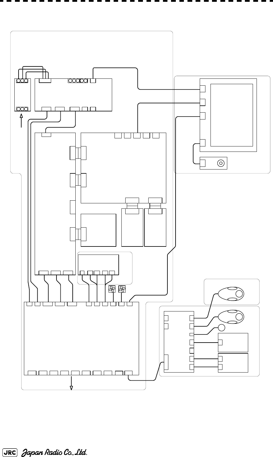
B-2
JMA-9172-SA Instruction Manual > B.DRAWINGS > B.1 Interconnection Diagram of Display Unit
B.1.1 NCD-9170
Fig B-1: Interconnection Diagram of NCD-9170
2P
J4308
26P
J4307
26P
J4306
50P
J4301
18P
J4304
8P
J4305
3P
J4313
3P
J4314
9P
J4309
14P
TB4101
TO TRU
TO ISW
26P
TB4201
TO EXT-RADAR
30P
TB4401
TO SENSOR
22P
TB4501
TO ALARM SYSTEM
22P
TB4601
TO GYRO
6P
TB4701
TO LOG
12P
TB4701
TO PC
9P
J4310
TERMINAL BOARD
CQD-2176
PC430
50P
J4302
50P
J4303
30P
J4311
TO OPU
30P
J4312
TO SUB OPU
6P
J6411
6P
J6410 6P
J6409
6P
J6408 2P
J6406 7P
J6405 14P
J6404 14P
J6403 15P
J6402
30P
J6401
OPERATION CIRCUIT D
CCK-1008
PC640
14P
J6101 15P
J6102
OPERATION
CIRCUIT A
CCK-1005
PC610
7P
J6201
OPERATION
CIRCUIT B
CCK-1006
PC620
SP1
A1
*PS/2 EXTENSION CABLE
(USER SUPPLY)
OPERATION UNIT
NCE-5322-R
2m H-7ZCRD1337 (NCE-5163-R )
JRC SUPPLY
B101
B102
PC900
11P
TB914
15P
TB913
11P
TB912
15P
TB911
2P
TB905
INTERSWITCH UNIT
NQE-3141-2A
CH1
CH2
50P
J4105
50P
J4106
50P
J4107
*OPTION
W401 H-7ZCRD1339
W402 H-7ZCRD1339
W403 H-7ZCRD1339
64P
J4103
64P
J4104
64P
J4102
64P
J4101
64P
J4401 64P
J4402 64P
J1
GYRO INTERFACE
CIRCUIT
CMJ-523
PC420
RADAR PROCESS
CIRCUIT
CDC-1362
PC440
MOTHERBOARD
CQC-1230
PC410
64P
J4403
64P
J4404
AIS PROCESS
CIRCUIT
CDC-1363
PC460
64P
J4601
64P
J4501
ARPA PROCESS
CIRCUIT
CDC-1364
PC450
15P
J4409
VGA
15P
J4405
VGA
28P
J4406
DVI-D
8P
J4407
RJ-45
50P
J4408
CF-card
LCD
OPERATION
CIRCUIT
CCK-1004 PC710
8P
J711
MONITOR UNIT
NWZ-178-R
LCD PANEL
H-7WSRD0002※
8P
H-7ZCRD1328
9P 2m H-7ZCRD1329A (NWZ-178-R)
DVI 2m H-7ZCRD1345 (NWZ-178-R)
20P
J4108
8P
POWER SUPPLY
CBD-1861
18P
20P
*PS/2 MOUSE/TRKBALL
(USER SUPPLY)
*OPTION
(USER SUPPLY)
2P
2P
AC OUT2
+
ー
U
V
W
BATTERY
IN
AC OUT2
AC IN
U
W
V
U
W
V
4351A07335 FILTER
INOUT
RED
WHT
BLU
RED
WHT
BLU
AC 2m VM0301-VM0303B2M (NWZ-178-R)
AC100-115V 50/60Hz
AC220-240V 50/60Hz NCD-9170(自立型) 機内接続図
Interconnection diagram of DISPLAY UNIT type NCD-9170 (self standing)
JMA-9172-SA
RADAR PROCESS UNIT
NDC-1478
SCANNER MOTOR
POWER
(“※” means revision of the specification document.)
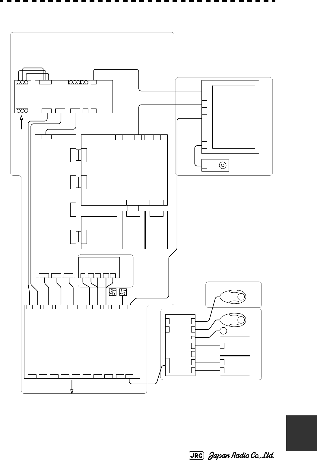
JMA-9172-SA Instruction Manual > B.DRAWINGS > B.1 Interconnection Diagram of Display Unit
B-3
B
B.1.2 NCD-9170T
Fig B-2: Interconnection Diagram of NCD-9170T
2P
J4308
26P
J4307
26P
J4306
50P
J4301
18P
J4304
8P
J4305
3P
J4313
3P
J4314
9P
J4309
14P
TB4101
TO TRU
TO ISW
26P
TB4201
TO EXT-RADAR
30P
TB4401
TO SENSOR
22P
TB4501
TO ALARM SYSTEM
22P
TB4601
TO GYRO
6P
TB4701
TO LOG
12P
TB4701
TO PC
9P
J4310
TERMINAL BOARD
CQD-2176
PC430
50P
J4302
50P
J4303
30P
J4311
TO OPU
30P
J4312
TO SUB OPU
6P
J6411
6P
J6410 6P
J6409
6P
J6408 2P
J6406 7P
J6405 14P
J6404 14P
J6403 15P
J6402
30P
J6401
OPERATION CIRCUIT D
CCK-1008
PC640
14P
J6101 15P
J6102
OPERATION
CIRCUIT A
CCK-1005
PC610
7P
J6201
OPERATION
CIRCUIT B
CCK-1006
PC620
SP1
A1
*PS/2 EXTENSION CABLE
(USER SUPPLY)
OPERATION UNIT
NCE-5322-RT
5m H-7ZCRD1338 (NCE-5322-RT)
JRC SUPPLY
B101
B102
PC900
11P
TB914
15P
TB913
11P
TB912
15P
TB911
2P
TB905
INTERSWITCH UNIT
NQE-3141-2A
CH1
CH2
50P
J4105
50P
J4106
50P
J4107
*OPTION
W401 H-7ZCRD1339
W402 H-7ZCRD1339
W403 H-7ZCRD1339
64P
J4103
64P
J4104
64P
J4102
64P
J4101
64P
J4401 64P
J4402 64P
J1
GYRO INTERFACE
CIRCUIT
CMJ-523
PC420
RADAR PROCESS
CIRCUIT
CDC-1362
PC440
MOTHERBOARD
CQC-1230
PC410
64P
J4403
64P
J4404
AIS PROCESS
CIRCUIT
CDC-1363
PC460
64P
J4601
64P
J4501
ARPA PROCESS
CIRCUIT
CDC-1364
PC450
15P
J4409
VGA
15P
J4405
VGA
28P
J4406
DVI-D
8P
J4407
RJ-45
50P
J4408
CF-card
LCD
OPERATION
CIRCUIT
CCK-1004 PC710
8P
J711
MONITOR UNIT
NWZ-178-RT
LCD PANEL
H-7WSRD0002※
8P
H-7ZCRD1328
9P 5m H-7ZCRD1330A (NWZ-178-RT)
DVI 5m H-7ZCRD1346 (NWZ-178-RT)
20P
J4108
8P
POWER SUPPLY
CBD-1861
18P
20P
*PS/2 MOUSE/TRKBALL
(USER SUPPLY)
*OPTION
(USER SUPPLY)
2P
2P
AC OUT2
+
ー
U
V
W
BATTERY
IN
AC OUT2
AC IN
U
W
V
U
W
V
4351A07335 FILTER
INOUT
RED
WHT
BLU
RED
WHT
BLU
AC 5m VM0301-VM0303B5M (NWZ-178-RT)
AC100-115V 50/60Hz
AC220-240V 50/60Hz NCD-9170T(卓上型) 機内接続図
Interconnection diagram of DISPLAY UNIT type NCD-9170T (desktop)
JMA-9172-SA
RADAR PROCESS UNIT
NDC-1478
SCANNER MOTOR
POWER
(“※” means revision of the specification document.)
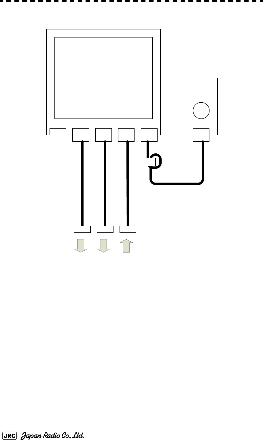
B-4
JMA-9172-SA Instruction Manual > B.DRAWINGS > B.1 Interconnection Diagram of Display Unit
B.1.3 NWZ-178-R
Fig B-3: Interconnection Diagram of NWZ-178-R
J7101
BRILL
AC100V
240V
FAN
ALM
DVIRGB
CCK-1004
PC710
H-7WSRD0002※
LCD
8P
H-7ZCRD1328
FL1
9P 2m H-7ZCRD1329A
DVI 2m H-7ZCRD1345
AC 2m VM0301-VM0303B2Mクロ
CDC-1362
J4406
CQD-2176
J4309
CBD-1861
OUTLET
(“※” means revision of the specification document.)
CML790-R (NWZ-178-R)
Monitor Unit Interconnection
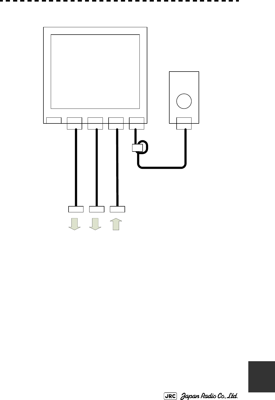
JMA-9172-SA Instruction Manual > B.DRAWINGS > B.1 Interconnection Diagram of Display Unit
B-5
B
B.1.4 NWZ-178-RT
Fig B-4: Interconnection Diagram of NWZ-178-RT
J7101
BRILL
AC100V
240V
FAN
ALM
DVIRGB
CCK-1004
PC710
H-7WSRD0002※
LCD
8P
H-7ZCRD1328
FL1
9P 5m H-7ZCRD1330A
DVI 5m H-7ZCRD1346
AC 5m VM0301-VM0303B5Mクロ
CDC-1362
J4406
CQD-2176
J4309
CBD-1861
OUTLET
(“※” means revision of the specification document.)
CML790-RT (NWZ-178-RT)
Monitor Unit Interconnection
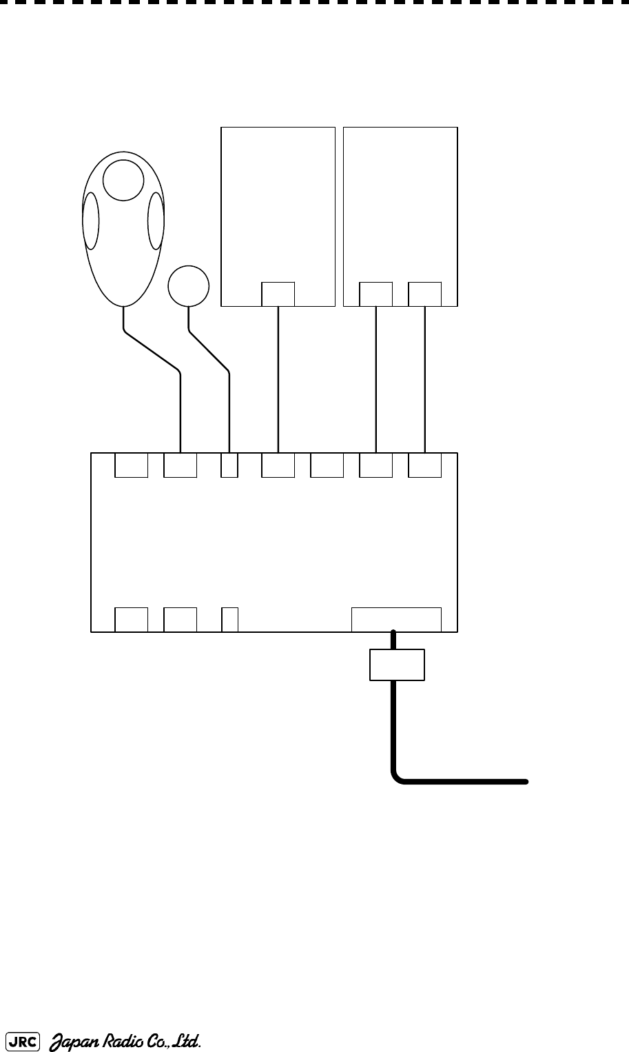
B-6
JMA-9172-SA Instruction Manual > B.DRAWINGS > B.1 Interconnection Diagram of Display Unit
B.1.5 NCE-5322-R
Fig B-5: Interconnection Diagram of NCE-5322-R
6P
J6411
6P
J6410 6P
J6409
6P
J6408 2P
J6406 7P
J6405 14P
J6404 14P
J6403 15P
J6402
30P
J6401
OPERATION CIRCUIT D
CCK-1008
PC640
14P
J6101 15P
J6102
OPERATION
CIRCUIT A
CCK-1005
PC610
7P
J6201
OPERATION
CIRCUIT B
CCK-1006
PC620
SP1
A1
OPERATION UNIT
NCE-5322-R
W67 2m H-7ZCRD1337
W62 H-7ZCRD1332
W65 H-7ZCRD1335
W63 H-7ZCRD1333A
W64 H-7ZCRD1334
FL1
2P
J6407
CMD-1031-R (NCE-5322-R)
Operation Unit Interconnection
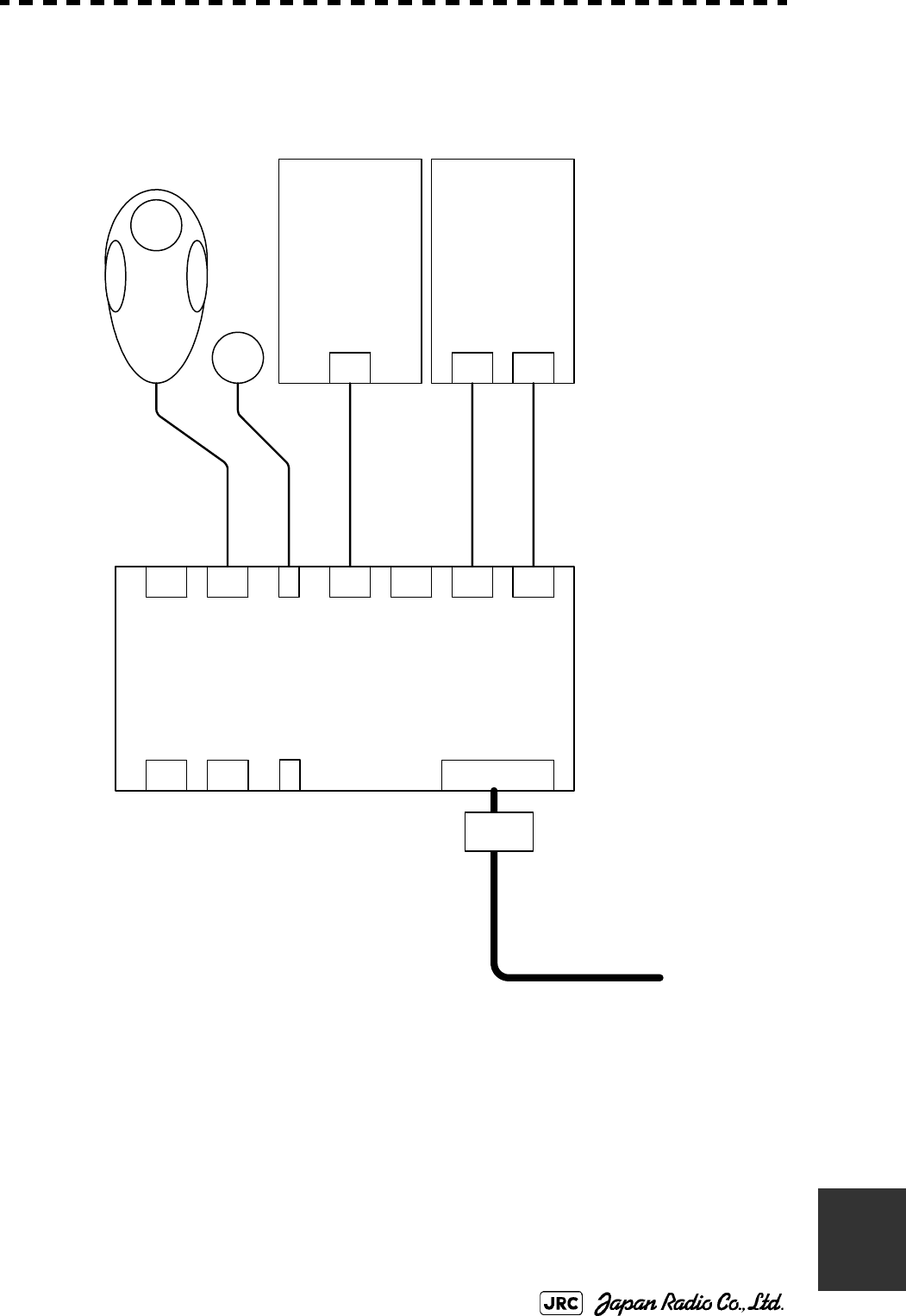
JMA-9172-SA Instruction Manual > B.DRAWINGS > B.1 Interconnection Diagram of Display Unit
B-7
B
B.1.6 NCE-5322-RT
Fig B-6: Interconnection Diagram of NCE-5322-RT
6P
J6411
6P
J6410 6P
J6409
6P
J6408 2P
J6406 7P
J6405 14P
J6404 14P
J6403 15P
J6402
30P
J6401
OPERATION CIRCUIT D
CCK-1008
PC640
14P
J6101 15P
J6102
OPERATION
CIRCUIT A
CCK-1005
PC610
7P
J6201
OPERATION
CIRCUIT B
CCK-1006
PC620
SP1
A1
OPERATION UNIT
NCE-5322-RT
W62 H-7ZCRD1332
W65 H-7ZCRD1335
W63 H-7ZCRD1333A
W64 H-7ZCRD1334
FL1
2P
J6407
W68 2m H-7ZCRD1338
CMD-1031-RT (NCE-5322-RT)
Operation Unit Interconnection
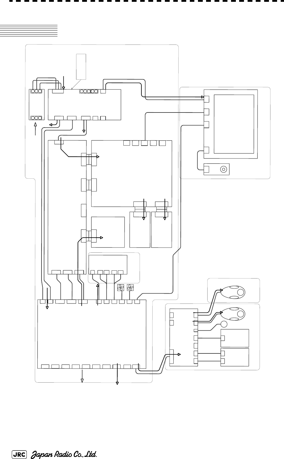
B-8
JMA-9172-SA Instruction Manual > B.DRAWINGS > B.2 Power System Diagram of Display Unit
B.2 Power System Diagram of Display Unit
Fig B-7: Power System Diagram of NCD-9170/T
2P
J4308
26P
J4307
26P
J4306
50P
J4301
18P
J4304
8P
J4305
3P
J4313
3P
J4314
9P
J4309
14P
TB4101
TO TRU
TO ISW
26P
TB4201
TO EXT-RADAR
30P
TB4401
TO SENSOR
22P
TB4501
TO ALARM SYSTEM
22P
TB4601
TO GYRO
6P
TB4701
TO LOG
12P
TB4701
TO PC
9P
J4310
TERMINAL BOARD
CQD-2176
PC430
50P
J4302
50P
J4303
30P
J4311
TO OPU
30P
J4312
TO SUB OPU
6P
J6411
6P
J64106P
J6409
6P
J64082P
J64067P
J640514P
J640414P
J640315P
J6402
30P
J6401
OPERATION CIRCUIT D
CCK-1008
PC640
14P
J610115P
J6102
OPERATION
CIRCUIT A
CCK-1005
PC610
7P
J6201
OPERATION
CIRCUIT B
CCK-1006
PC620
SP1
A1
*PS/2 EXTENSION CABLE
(USER SUPPLY)
OPERATION UNIT
NCE-5322-R/RT
2m H-7ZCRD1337 (NCE-5163-R ) / self standing
5m H-7ZCRD1338 (NCE-5322-RT) / desktop
JRC SUPPLY
B101
B102
PC900
11P
TB914
15P
TB913
11P
TB912
15P
TB911
2P
TB905
INTERSWITCH UNIT
NQE-3141-2A
CH1
CH2
50P
J4105
50P
J4106
50P
J4107
*OPTION
W401 H-7ZCRD1339
W402 H-7ZCRD1339
W403 H-7ZCRD1339
64P
J4103
64P
J4104
64P
J4102
64P
J4101
64P
J440164P
J440264P
J1
GYRO INTERFACE
CIRCUIT
CMJ-523
PC420
RADAR PROCESS
CIRCUIT
CDC-1362
PC440
MOTHERBOARD
CQC-1230
PC410
64P
J4403
64P
J4404
AIS PROCESS
CIRCUIT
CDC-1363
PC460
64P
J4601
64P
J4501
ARPA PROCESS
CIRCUIT
CDC-1364
PC450
15P
J4409
VGA
15P
J4405
VGA
28P
J4406
DVI-D
8P
J4407
RJ-45
50P
J4408
CF-card
LCD
OPERATION
CIRCUIT
CCK-1004 PC710
8P
J711
MONITOR UNIT
NWZ-178-R/RT
LCD PANEL
H-7WSRD0002※
8P
H-7ZCRD1328
9P 2m H-7ZCRD1329A (NWZ-178-R )
9P 5m H-7ZCRD1330A (NWZ-178-RT)
DVI 2m H-7ZCRD1345 (NWZ-178-R )
DVI 5m H-7ZCRD1346 (NWZ-178-RT)
20P
J4108
8P
POWER SUPPLY
CBD-1861
18P
20P
*PS/2 MOUSE/TRKBALL
(USER SUPPLY)
*OPTION
(USER SUPPLY)
2P
2P
AC OUT2
+
ー
U
V
W
BATTERY
IN
AC OUT2
AC IN
U
W
V
U
W
V
4351A07335 FILTER
INOUT
RED
WHT
BLU
RED
WHT
BLU
AC 2m VM0301-VM0303B2M (NWZ-178-R )
AC 5m VM0301-VM0303B5M (NWZ-178-RT)
AC100-115V 50/60Hz
AC220-240V 50/60Hz
NCD-9170/T電源系統図
Power Supply system diagram of DISPLAY UNIT type NCD-9170/T
RADAR PROCESS UNIT
NDC-1478
SCANNER MOTOR
POWER
INPUT VOLTAGE
SELECT SWITCH
AC100-115V
AC220-240V
50/60Hz,1φ
5V
3.3V
U,V
AC100-115V
AC220-240V
50/60Hz,1φ
3.3V,5V,
12V,-12V
3.3V,5V,
12V,-12V
3.3V,5V,12V,-12V
+48V,DC+24V
P+12V
3.3V,5V,12V,-12V
+48V,DC+24V
P+5V
P+5V
+48V
(to SCANNER UNIT)
P+12V
DC+24V
+5V
(“※” means revision of the specification document.)
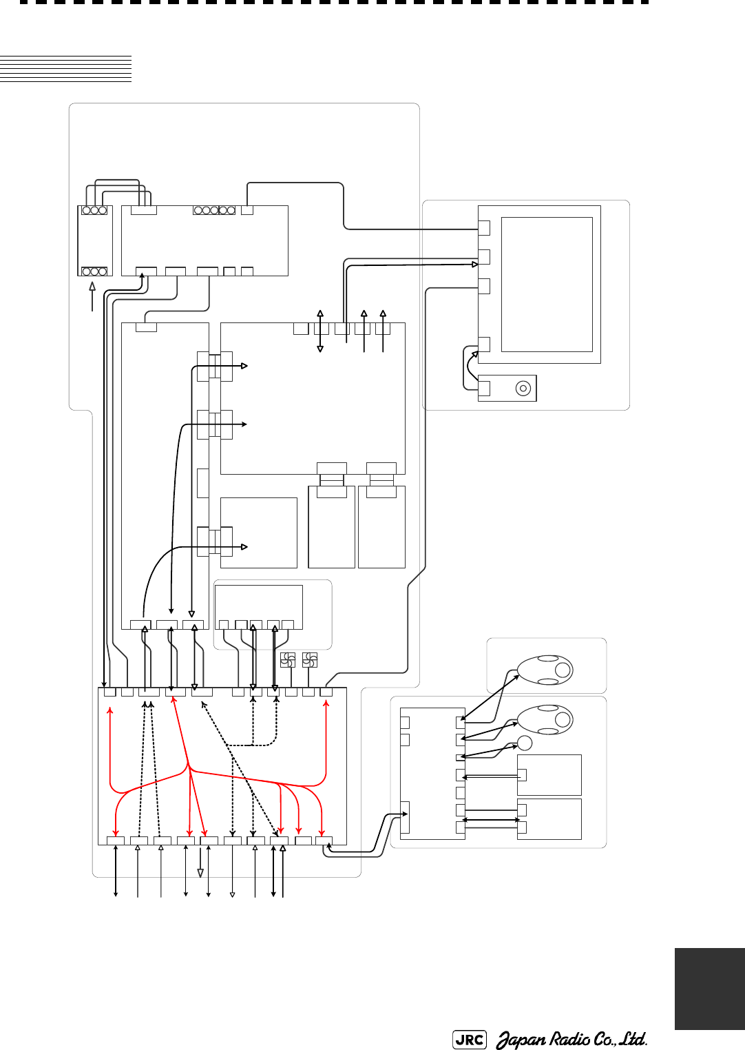
JMA-9172-SA Instruction Manual > B.DRAWINGS > B.3 Signal Flow Diagram of Display Unit
B-9
B
B.3 Signal Flow Diagram of Display Unit
Fig B-8: Signal Flow Diagram of NCD-9170/T
2P
J4308
26P
J4307
26P
J4306
50P
J4301
18P
J4304
8P
J4305
3P
J4313
3P
J4314
9P
J4309
14P
TB4101
TO TRU
TO ISW
26P
TB4201
TO EXT-RADAR
30P
TB4401
TO SENSOR
22P
TB4501
TO ALARM SYSTEM
22P
TB4601
TO GYRO
6P
TB4701
TO LOG
12P
TB4701
TO PC
9P
J4310
TERMINAL BOARD
CQD-2176
PC430
50P
J4302
50P
J4303
30P
J4311
TO OPU
30P
J4312
TO SUB OPU
6P
J6411
6P
J6410 6P
J6409
6P
J6408 2P
J6406 7P
J6405 14P
J6404 14P
J6403 15P
J6402
30P
J6401
OPERATION CIRCUIT D
CCK-1008
PC640
14P
J6101 15P
J6102
OPERATION
CIRCUIT A
CCK-1005
PC610
7P
J6201
OPERATION
CIRCUIT B
CCK-1006
PC620
SP1
A1
*PS/2 EXTENSION CABLE
(USER SUPPLY)
OPERATION UNIT
NCE-5322-R/RT
2m H-7ZCRD1337 (NCE-5163-R ) / self standing
5m H-7ZCRD1338 (NCE-5322-RT) / desktop
JRC SUPPLY
B101
B102
PC900
11P
TB914
15P
TB913
11P
TB912
15P
TB911
2P
TB905
INTERSWITCH UNIT
NQE-3141-2A
CH1
CH2
50P
J4105
50P
J4106
50P
J4107
*OPTION
W401 H-7ZCRD1339
W402 H-7ZCRD1339
W403 H-7ZCRD1339
64P
J4103
64P
J4104
64P
J4102
64P
J4101
64P
J4401 64P
J4402 64P
J1
GYRO INTERFACE
CIRCUIT
CMJ-523
PC420
RADAR PROCESS
CIRCUIT
CDC-1362
PC440
MOTHERBOARD
CQC-1230
PC410
64P
J4403
64P
J4404
AIS PROCESS
CIRCUIT
CDC-1363
PC460
64P
J4601
64P
J4501
ARPA PROCESS
CIRCUIT
CDC-1364
PC450
15P
J4409
VGA
15P
J4405
VGA
28P
J4406
DVI-D
8P
J4407
RJ-45
50P
J4408
CF-card
LCD
OPERATION
CIRCUIT
CCK-1004 PC710
8P
J711
MONITOR UNIT
NWZ-178-R/RT
8P
H-7ZCRD1328
9P 2m H-7ZCRD1329A (NWZ-178-R )
9P 5m H-7ZCRD1330A (NWZ-178-RT)
DVI 2m H-7ZCRD1345 (NWZ-178-R )
DVI 5m H-7ZCRD1346 (NWZ-178-RT)
20P
J4108
8P
POWER SUPPLY
CBD-1861
18P
20P
*PS/2 MOUSE/TRKBALL
(USER SUPPLY)
*OPTION
(USER SUPPLY)
2P
2P
AC OUT2
+
ー
U
V
W
BATTERY
IN
AC OUT2
AC IN
U
W
V
U
W
V
4351A07335 FILTER
INOUT
RED
WHT
BLU
RED
WHT
BLU
AC 2m VM0301-VM0303B2M (NWZ-178-R )
AC 5m VM0301-VM0303B5M (NWZ-178-RT)
AC100-115V 50/60Hz
AC220-240V 50/60Hz NCD-9170/T 信号系統図
Signal flow diagram of DISPLAY UNIT type NCD-9170/T
RADAR PROCESS UNIT
NDC-1478
SCANNER MOTOR
POWER
KEY matrix
Encoder
Power SW
Audio
PS/2
I/F
PS/2
I/F
Serial
Radar video,
Trigger, Rotation
Serial
Radar video,
Trigger, Rotation
Radar video,
Trigger, Rotation
Serial
Dry Contact
GYRO
(STEP/SYNC)
GYRO
(PULSE/SYNC)
Serial
Radar video,
Trigger, Rotation
Radar video,
Trigger, Rotation
Radar video,
Trigger, Rotation
Serial, GPIO
GYRO/LOG
Radar video,
Trigger, Rotation Serial, GPIO GYRO/LOG
Analog RGB
Analog RGB
Ethernet
Digital Video Interface
Dimmer
Power supply Control
Power supply Fan alarm
Power supply Control
Power supply Fan alarm
LCD Fan Alarm
LCD PANEL
H-7WSRD0002※
(“※” means revision of the specification document.)
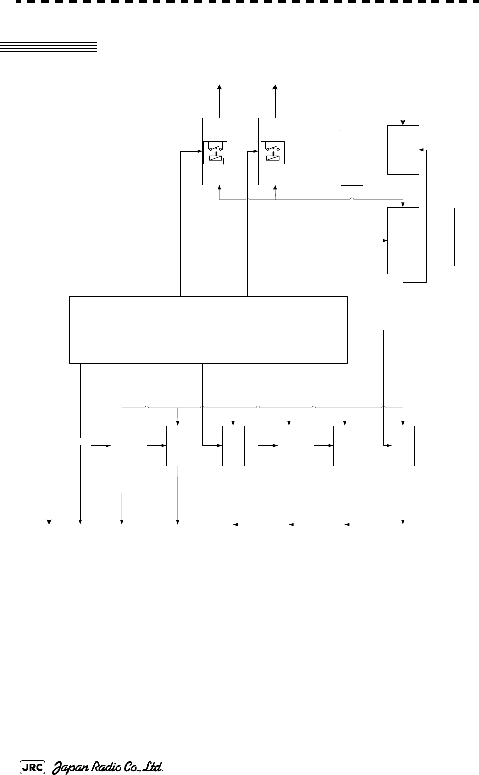
B-10
JMA-9172-SA Instruction Manual > B.DRAWINGS > B.4 Primary Power System Diagram
B.4 Primary Power System Diagram
Fig B-9: Primary Power System Diagram
POWER CONTROL
CIRCUIT
FAN ALM POWER CONTROL
INTERSWITCH=1A
OPERATION UNIT=0.5A(typ)
GYRO I/F CIRCUIT=0.1A(typ)
SCANNER
X BAND_2.5A, S BAND_3.0A
RADAR PROCESS CIRCUIT = 1.2A(typ)
ARPA PROCESS CIRCUIT = 0.15A(typ)
AIS PROCESS CIRCUIT = 0.15(typ)
TERMINAL BOARD = 1.0A(typ)
AC100-115V
AC220-240V
50/60Hz,1φ
SCANNER
MOTOR
POWER
AC100/230V
1φ
OVER VOLTAGE
PROT ECTION
AC100-115V
AC220-240V
50/60Hz,1φ
RADAR PROCESS CIRCUIT = 2.2A(typ)
ARPA PROCESS CIRCUIT = 0.1A(typ)
AIS PROCESS CIRCUIT = 0.1(typ)
TERMINAL BOARD = 0.2A(typ)
RADAR PROCESS CIRCUIT = 0.1A(typ)
TERMINAL BOARD = 0.4A(typ)
RADAR PROCESS CIRCUIT = 0.1A(typ)
TERMINAL BOARD = 0.1A(typ)
BATTRY
DC24V
OPERATION UNIT = 0.1A
P+12V
+48V±3V
+5. 0V
+3. 3V
-12V
+12V
CIRCUIT
BREAKER LINE FI LT ER
VOLTAGE SELCT
SWITCH
MONITOR UNIT
POWER
SCANNER MOTOR
POWER

JMA-9172-SA Instruction Manual > B.DRAWINGS > B.5 Block Diagram of Scanner Unit
B-11
B
B.5 Block Diagram of Scanner Unit
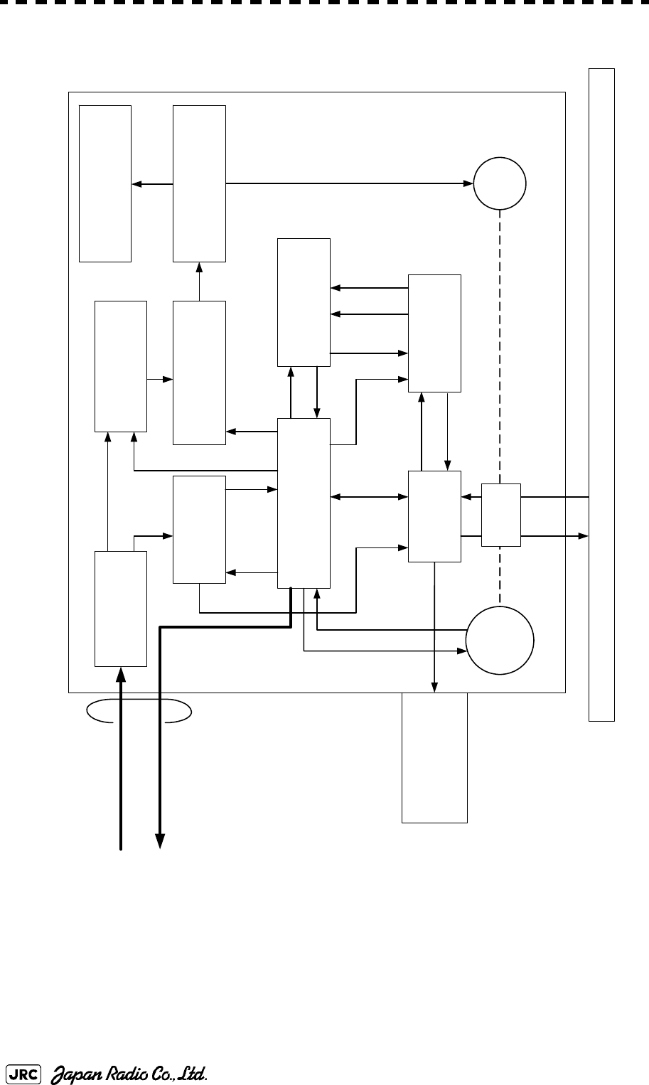
B-12
JMA-9172-SA Instruction Manual > B.DRAWINGS > B.5 Block Diagram of Scanner Unit
B.5.1 NKE-1532
Fig B-10: Block Diagram of NKE-1532
Slot Antenna
TRX
CMN-750
IF Input/Output
CHA-396
Radar Processor
CDC-1349
Interface
CMH-2246
Power Supply
CBD-1798
DC
Motor Encoder
*1 PM Antenna
(External)
Clock
TX_IF_Analog
Motor Driver
CBD-2010 (AC220V)/
CBD-2011 (AC100V)
RX_IF_Analog
Relay and Filter
CSC-1656
+15V, ±12V,
+5V, -2.5V
+5V, +3.3V,
-2.5V
+28V
Safety Switch
CSD-1656
Brake
CFA-1255
RX_RF
PM_OUT
DC48V
RX_IF_Digital
TX_IF_Digital
+15V
+12V(ON/OFF Control)
Control
+28V
Absorbable
Recovery Current
DC280V
BP, BZ
TX_RF
BP, BZ, TRIG, MTR, VD
NKE-1532 (Scanner)
14 cores
composite cable
Terminal Board
TB102 DC48V,
AC100V/AC220V
Display Unit
NCD-9170
Control,
±12V, +5V
Control,
+3.3V
AC100V/220V
Rotary
Joint
+12V
Control
Note *1 PM (Performance Monitor)
AC100V/220V
AC100V/220V

JMA-9172-SA Instruction Manual > B.DRAWINGS > B.6 Interconnection Diagram of Scanner Unit
B-13
B
B.6 Interconnection Diagram of Scanner Unit
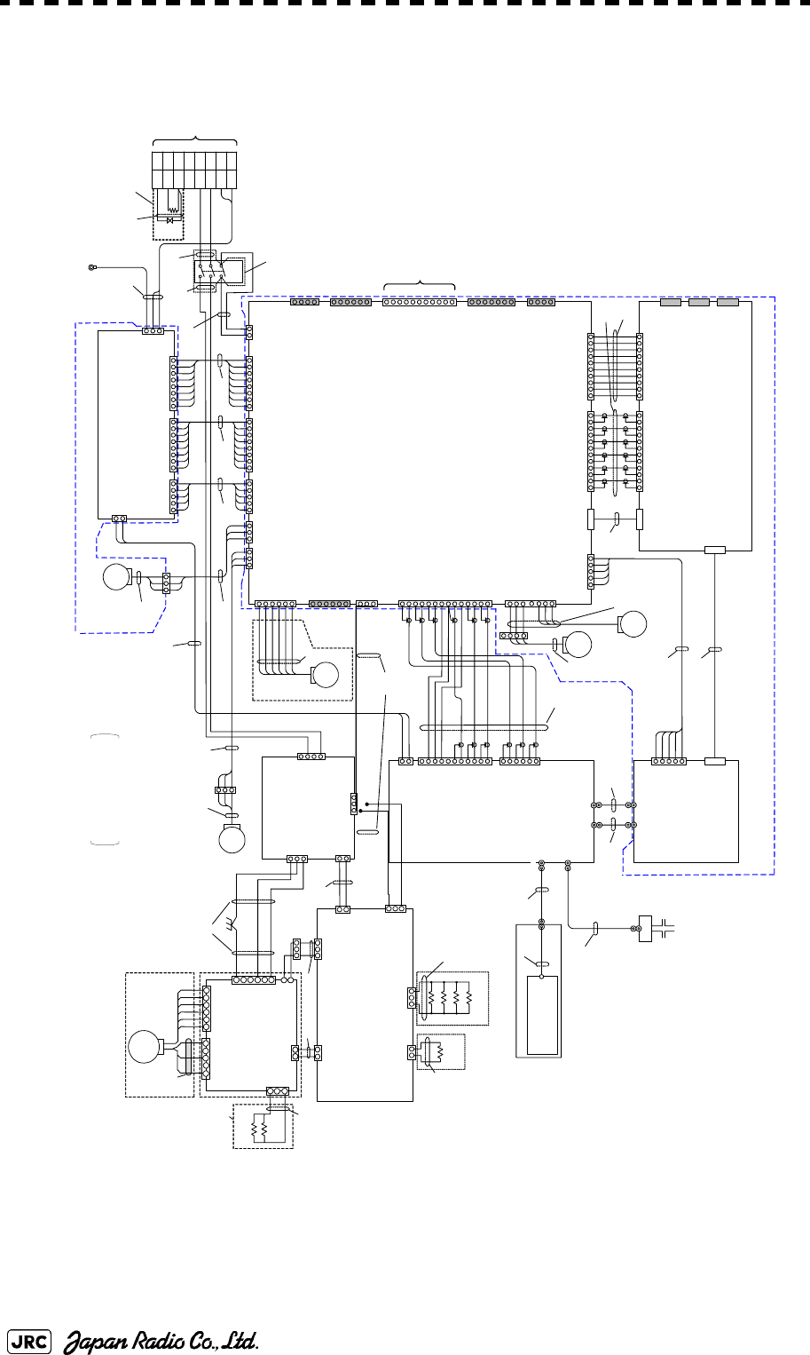
B-14
JMA-9172-SA Instruction Manual > B.DRAWINGS > B.6 Interconnection Diagram of Scanner Unit
B.6.1 NKE-1532 (AC110V)
Fig B-11: Interconnection Diagram of NKE-1532 (AC110V)
1.1A
2.2A
3.FG
1.+15VD
2.+12VD
3.+5VD
4.+5VD
5.GND1
6.GND1
7.GND2
8.GND2
1.+12VA
2.-12VA
3.+5VA
4.+5VA
5.-2. 5VA
6.GND 3
7.GND3
8.GND4
1.+32VA
2.GND2
1.+32V_CNT
2.+15V_CNT
3.PS_FAIL
4.SPC_FAIL
5.GND1
PC1101
POWER SUPPLY CIRCUIT
CBD-1798
CSD-1656
ZCRD1582※
(W302)
ZCRD1583※
P1201
P1211
DISPLAY
UNIT
(W301)
S101
S-32
3
5
8
2
9
6
SAFETY SWITCH
YEL
BLK
WHT
BLU
RED
SHIELD
ENCODERCHT-1071
P13
(W019)
B103
(for RADAR PROCESS UNIT)
P2211
SE
B102
1.+15VD
2.+12VD
3.+5VD
4.+5VD
5.DGND
6.DGND
7.DGND
8.DGND
1.+12VA
2.-12VA
3.+5VA
4.+5VA
5.-2.5VA
6.AGND
7.AGND
8.AGND
1.+32V_CNT
2.+15V_CNT
3.PS_FAIL
4.SPC_FAIL
5.DGND_PWR
1.+12VD
2.C2
1.VD
2.VDE
3.MTR+
4.MTR-
1.TIY
2.TIYE
3.BP
4.BPE
5.BZ
6.BZE
IL-G-6P
IL-G-4P
1.BP+
2.BP-
3.BZ+
4.BZ-
5.TRIG+
6.TRIG-
7.MTR+
8.MTR-
9.MTRE
10.VD+
11.VD-
MSTBA2.5/11-G
1.MNT_TX+
2.MNT_TX-
3.MNT_TXE
4.MNT_RX+
5.MNT_RX-
6.MNT_RXE
7.DGND
1.+5VD
2.+5VD
3.DGND
4.DGND
IL-7P
B4P-SHF
1.+12VA
2.-12VA
3.+5VA
4.AGND
5.+5VD
6.+5VD
7.+3.3VD
8.DGND
9.DGND
10.DGND
B10P-VH
1.SP_ID_MONI
2.AGND
3.SP_TX_MONI_SP
4.AGND
5.SP_TX_MONI_CP
6.AGND
7.SP_VD_ERR
8.AGND
9.SP_VD
10.AGND
11.SP_RF_STC
12.AGND
IL_G_12P
8830E-060-170L-F
1.IT_ID_MONI
2.AGND
3.IT_TX_MONI_SP
4.AGND
5.IT_TX_MONI_CP
6.AGND
7.IT_VD_ERR
8.AGND
9.IT_VD
10.AGND
11.IT_RF_STC
12.AGND
IL_G_12P
1.+12VA
2.-12VA
3.+5VA
4.AGND
5.+5VD
6.+5VD
7.+3.3VD
8.DGND
9.DGND
10.DGND
B10P-VH
1.+5VA
2.-2.5VA
3.AGND
4.+3.3VD
5.DGND
B5P-SHF
1.RF_GATE
2.DG ND
3.PM _GAT E
4.DG ND
5.PLL _DE T
6.LO _MOD E
7.DGND
8.RE F_MO DE
9.RF_STC
10.A GND
11.TX_MONI
12.AGND
13.ID _MONI
14.A GND
IL_G_14P
B8P-VH
B8P-VH B8P-SHF
B8P-SHF
IL-G-6P
IL-G-5P
IL-G-2P
B02P-VL
B03P-VL
1.HMCNT
2.+15VD
3.DGND
B3P-SHF
1.MCT
2.MBK
3.(N.C.)
4.DGND_MOTOR
5.MPS
6.MIER
IL-G-5P
1.+12VD
2.DGND
3.FAN_ERR1
IL-G-7P
5.+12VD
6.DG ND
7.FAN _ERR2
1.+12VD
2.DGND
3.FAN_ERR4
IL-G-3P
8830E-100-170 S-F
8830E-060-170S-F
8830E-050-170S-F
HIF3FC-10PA-2.54DSA
XG4C-1431
IL-6P
1.PHZ
2.DGND
3.PHA
4.PHB
5.+12VD
6.DGND
1.-2.5VA
2.+5VA
3.AGND
4.+3.3VD
5.DGND
B5P-SHF
IF_OUT(Rx)
5.TX_DET
6.GND
2.GND
1.TX_GATE
2.GND
3.PM_GATE
4.GND
5.LO_CH
6.GND
7.GND
FAN
Φ120
RED
BLK
YEL
FAN
Φ60
8830E-100-170S- F
DISPLAY UNIT
↑ANTENNA
WHT.T
RED.T
BLK.T
RED.T
J3
J1102 J1103
J1104
J1101
TB101
J1
J2
J13
J2201 J2202
J2203 J2204
J2205
J2206
J2207
J2217
J2211
J2210
J2216
J2212
J2215
PC2201
INTERFACE CIRCUIT
CMH-2246
J2208
J2209
J2601
J2604
J2602
J2603
J2605
J2606
J2607
PC2601
RADAR PROCESS CIRCUIT
CDC-1349 PC3401
IF INPUT/OUTPUT CIRCUIT
CHA-396
PC3001
TRX MODULE
CMN-750
J3001
J3002
J3006
J3004
HRM-300-386B
HRM-300-376B
DF3DZ-11P-2H
DF3DZ-6P-2H
J3401
J3402
J3403
B106
(for POWER SUPPLY UNIT)
RF_ANT
PM_OUT
P1101
P1104
P1102
P1103
P3
P2216 P2201
P2202 P2207
P2215
P2206
P2212
P2204P2208P2209
P2203
P2601 P2603 P2602
P2604 P3401
P3402
P3403
P3001
P3003
P3002
P3004
ZCRD1584※
(W303)
ZCRD1564※
(W007)
ZCRD1565※
(W008) ZCRD1566※
(W009)
ZCRD1567※
(W010)
ZCRD1563※
(W006)
ZCRD1562※
(W005)
ZCRD1561※
(W004)
ZCRD1576※
(W101)
ZCRD1560※
(W003)
ZCRD1558※
(W001)
ZCRD1559※
(W002)
ZCRD1578※
(W201)
ZCRD1579※
(W202)
P3601
J3601
TMA2302-10
(TRANSDUCER)
(ROTARY JOINT)
(SemiRigid)
IF_OUT(Tx)
IF_IN(Rx)
FAN
Φ60
1.+12VD
2.DGND
3.FAN_ERR3
IL-G-3P
J2214
P2214
1.PA_I
3.STC
4.GND
IF_IN(Tx)
8.PLL_DET
9.GND
10.REF_MODE
11.GND
1.+32V
2.GND
J3003 DF22-2P-7.92DS
P3006
ZCRD1580※
(W203)
+48V +48V
+48VG
U1
V1
W1
UTH
U
V
U1
V1
W1
UTH
U
V
TB102
+48VG
RED
YEL
BLK.T
RED
BLK
YEL
RED
BLK
YEL
RED
BLK
YEL
B105
(for MOTOR DRIVER)
J1902
P1902
J1901 P1901
ZCRD1573※
(W017)
ZCRD1571※
(W015)
ZCRD1569※
(W013)
ZCRD1572※
(W016)
ZCRD1574※
(W018)
PERFORMANCE MONITOR
CIRCUIT
7PCRD1892
ZCRD1581※
(W204)
(SMA type connector)
P3901
J3901
FG
RED.T
BLK.T
WHT.T
RED.T
GRN.T
ZCRD1575※
MOTOR DRIVER
CBD-2011
BREAK CIRCUIT
CFA-1255
J1501
1.VERR
2.E
H-7EPRD00 35
B201
J1505
PC1501
P1501
B2P-VH
P1505
1.VERR1
2.E
1.VERR
2.E
1.P
2.NC
3.N
1. P
2. N
1.BKH1
3.BKH2
1.BKS1
2.BKS2
1.+15V
2.NC
3.+15VE
P1941 J1941
J1903
P1903
J1905
P1905
J1912
P1912
BRAKE CONTROL CIRCUIT
CCB-1655
P1502
J1921
P1921
J1911
P1911
1.RED
3.BLK
J1511
P1511
IL-2P
S3B-XH -A
1-350210-0 1-3502 09-0
1-480700-0
ZCRD1632※
(W311) ZCRD1606※
(W307)
ZCRD1586※
(W305)
(100V)
WC1
ZCRD1543※
(W309)
ZCRD1544※
(W310)
BRAKE CIRCUIT B
CFA-1262
BRAKE CIRCUIT A
CFA-1261
R1
R2
R3
R4
R1
120Ω
30W
330Ω
30W
×4
×1
2.NC
4.NC
1.S1
2.S2
3.S3
4.S4
5.S5
6.S6
J1502
J1503
3.M2
1.M1
5.M3
P1503
MOTOR
MOTOR
B101
CBP-1205
H-7BDRD004 9
2.NC
(W304)
ZCRD1316※
R1
R2
1.2kΩ
10W
P1504
1.R1
3.R2
J1504
B3P-VH
2.NC
3.MV2
1.MU2
2.NC
4.NC
5.NC
6.GND
B6P-VH
B2P-VH
C.G.
RED
BLK
GRN
GRN
J1201
1.U1
3.V1
2.NC
4.NC
B4P-VH
RED.T
IL-3P
1.HMCNT
2.+15V
3.GND
J1211
1.VERR1
2.E
IL-2P
J1212 P1212
RELAY FILTER CIRCUIT
CSC-1656
PC1201 1.MU2
3.MV2
J1202
2.GND
P1202
RED
BLK
YEL
ZCRD1587※
(W306)
J3007 J3008
P3007 P3008
RED
BLK
YEL
FAN
Φ92
(W014)
ZCRD1570※
B107
(for RADAR PROCESS UNIT)
J3404
P3404
(W21)
ZCRD1608※
(W20)
ZCRD1607※
PC3601
PERFORMANCE MONITOR
CAY-71
B3P-NV
POWER SUPPLY UNIT
NBD-890
RADAR PROCESS UNIT
INTERCONNECTION
CMP-482
RADAR PROCESS UNIT
NDC-1493
RADAR PROCESS
UNIT
INTERCONNECTION
CMC-1359
SCANNER UNIT
INTERCONNECTION
CAX-16
4.(接続なし)
J1903 P1903
RED
BLK
YEL
TH101
TR101
(200W)
RED.T
RED.T
WHT.T
WHT.T
(W401)
ZCRD15 09※
HEATER CONTROL PART
CHG-215
(OPTION)
NKE-1532(AC110V)
SCANNER UNIT INTERCONNECTION
空中線機内接続図
S300W SSR 2unit
(SMA type connecto r)
(N type connector)
(SMA type connector)
(SMA type conne ctor)
(SMA type connector)
H-7ZCRD####*:
“#” means specification document No.
“*” means revision of the specfication document.
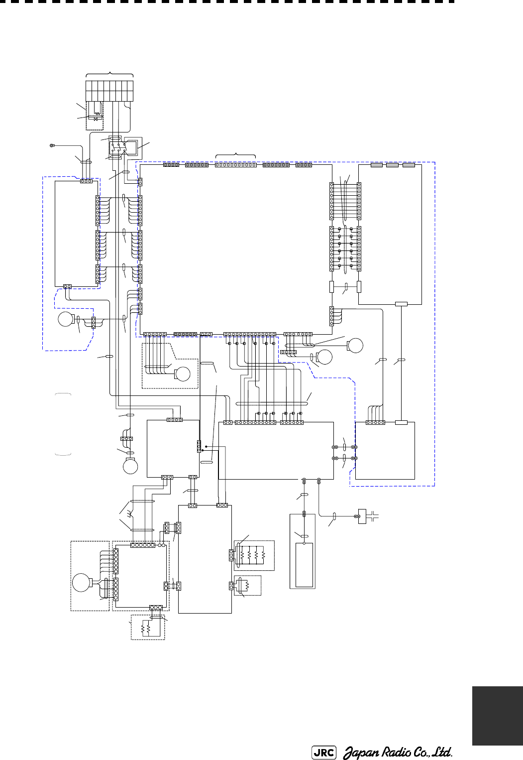
JMA-9172-SA Instruction Manual > B.DRAWINGS > B.6 Interconnection Diagram of Scanner Unit
B-15
B
B.6.2 NKE-1532 (AC220V)
Fig B-12: Interconnection Diagram of NKE-1532 (AC220V)
1.1A
2.2A
3.FG
1.+15VD
2.+12VD
3.+5VD
4.+5VD
5.GND1
6.GND1
7.GND2
8.GND2
1.+12VA
2.-12VA
3.+5VA
4.+5VA
5.-2.5VA
6.GND3
7.GND3
8.GND4
1.+32VA
2.GND2
1.+32V_CNT
2.+15V_CNT
3.PS_FAIL
4.SPC_FAIL
5.GND1
PC1101
POWER SUPPLY CIRCUIT
CBD-1798
CSD-1656
ZCRD1582※
(W302)
ZCRD1583※
P1201
P1211
DISPLAY
UNIT
(W301)
S101
S-32
3
5
8
2
9
6
SAFETY SWITCH
YEL
BLK
WHT
BLU
RED
SHIELD
ENCODERCHT-1071
P13
(W019)
B103
(for RADAR PROCESS UNIT)
P2211
SE
B102
1.+15VD
2.+12VD
3.+5VD
4.+5VD
5.DGND
6.DGND
7.DGND
8.DGND
1.+12VA
2.-12VA
3.+5VA
4.+5VA
5.-2.5VA
6.AGND
7.AGND
8.AGND
1.+32V_CNT
2.+15V_CNT
3.PS_FAIL
4.SPC_FAIL
5.DGND_PWR
1.+12VD
2.C2
1.VD
2.VDE
3.MTR+
4.MTR-
1.TIY
2.TIYE
3.BP
4.BPE
5.BZ
6.BZE
IL-G-6P
IL-G-4P
1.BP+
2.BP-
3.BZ+
4.BZ-
5.TRIG+
6.TRIG-
7.MTR+
8.MTR-
9.MTRE
10.VD+
11.VD-
MSTBA2.5/11-G
1.MNT_TX+
2.MNT_TX-
3.MNT_TXE
4.MNT_RX+
5.MNT_RX-
6.MNT_RXE
7.DGND
1.+5VD
2.+5VD
3.DGND
4.DGND
IL-7P
B4P-SHF
1.+12VA
2.-12VA
3.+5VA
4.AGND
5.+5VD
6.+5VD
7.+3.3VD
8.DGND
9.DGND
10.DGND
B10P-VH
1.SP_ID_MONI
2.AGND
3.SP_TX_MONI_SP
4.AGND
5.SP_TX_MONI_CP
6.AGND
7.SP_VD_ERR
8.AGND
9.SP_VD
10.AGND
11.SP_RF_STC
12.AGND
IL_G_12P
8830E-060-170L-F
1.IT_ID_MONI
2.AGND
3.IT_TX_MONI_SP
4.AGND
5.IT_TX_MONI_CP
6.AGND
7.IT_VD_ERR
8.AGND
9.IT_VD
10.AGND
11.IT_RF_STC
12.AGND
IL_G_12P
1.+12VA
2.-12VA
3.+5VA
4.AGND
5.+5VD
6.+5VD
7.+3.3VD
8.DGND
9.DGND
10.DGND
B10P-VH
1.+5VA
2.-2.5VA
3.AGND
4.+3.3VD
5.DGND
B5P-SHF
1.RF_GATE
2.DG ND
3.PM _GAT E
4.DG ND
5.PLL _DE T
6.LO _MOD E
7.DGND
8.RE F_MO DE
9.RF_STC
10.A GND
11.TX_MONI
12.AGND
13.ID _MONI
14.A GND
IL_G_14P
B8P-VH
B8P-VH B8P-SHF
B8P-SHF
IL-G-6P
IL-G-5P
IL-G-2P
B02P-VL
B03P-VL
1.HMCNT
2.+15VD
3.DGND
B3P-SHF
1.MCT
2.MBK
3.(N.C.)
4.DGND_MOTOR
5.MPS
6.MIER
IL-G-5P
1.+12VD
2.DGND
3.FAN_ERR1
IL-G-7P
5.+12VD
6.DG ND
7.FAN _ERR2
1.+12VD
2.DGND
3.FAN_ERR4
IL-G-3P
8830E-100-170 S-F
8830E-060-170S-F
8830E-050-170S-F
HIF3FC-10PA-2.54DSA
XG4C-1431
IL-6P
1.PHZ
2.DGND
3.PHA
4.PHB
5.+12VD
6.DGND
1.-2.5VA
2.+5VA
3.AGND
4.+3.3VD
5.DGND
B5P-SHF
IF_OUT(Rx)
5.TX_DET
6.GND
2.GND
1.TX_GATE
2.GND
3.PM_GATE
4.GND
5.LO_CH
6.GND
7.GND
FAN
Φ120
RED
BLK
YEL
FAN
Φ60
8830E-100-170S- F
DISPLAY UNIT
↑ANTENNA
WHT.T
RED.T
BLK.T
RED.T
J3
J1102 J1103
J1104
J1101
TB101
J1
J2
J13
J2201 J2202
J2203 J2204
J2205
J2206
J2207
J2217
J2211
J2210
J2216
J2212
J2215
PC2201
INTERFACE CIRCUIT
CMH-2246
J2208
J2209
J2601
J2604
J2602
J2603
J2605
J2606
J2607
PC2601
RADAR PROCESS CIRCUIT
CDC-1349 PC3401
IF INPUT/OUTPUT CIRCUIT
CHA-396
PC3001
TRX MODULE
CMN-750
J3001
J3002
J3006
J3004
HRM-300-386B
HRM-300-376B
DF3DZ-11P-2H
DF3DZ-6P-2H
J3401
J3402
J3403
B106
(for POWER SUPPLY UNIT)
RF_ANT
PM_OUT
P1101
P1104
P1102
P1103
P3
P2216 P2201
P2202 P2207
P2215
P2206
P2212
P2204P2208P2209
P2203
P2601 P2603 P2602
P2604 P3401
P3402
P3403
P3001
P3003
P3002
P3004
ZCRD1584※
(W303)
ZCRD1564※
(W007)
ZCRD1565※
(W008) ZCRD1566※
(W009)
ZCRD1567※
(W010)
ZCRD1563※
(W006)
ZCRD1562※
(W005)
ZCRD1561※
(W004)
ZCRD1576※
(W101)
ZCRD1560※
(W003)
ZCRD1558※
(W001)
ZCRD1559※
(W002)
ZCRD1578※
(W201)
ZCRD1579※
(W202)
P3601
J3601
TMA2302-10
(TRANSDUCER)
(ROTARY JOINT)
(SemiRigid)
IF_OUT(Tx)
IF_IN(Rx)
FAN
Φ60
1.+12VD
2.DGND
3.FAN_ERR3
IL-G-3P
J2214
P2214
1.PA_I
3.STC
4.GND
IF_IN(Tx)
8.PLL_DET
9.GND
10.REF_MODE
11.GND
1.+32V
2.GND
J3003 DF22-2P-7.92DS
P3006
ZCRD1580※
(W203)
+48V +48V
+48VG
U1
V1
W1
UTH
U
V
U1
V1
W1
UTH
U
V
TB102
+48VG
RED
YEL
BLK.T
RED
BLK
YEL
RED
BLK
YEL
RED
BLK
YEL
B105
(for MOTOR DRIVER)
J1902
P1902
J1901 P1901
ZCRD1573※
(W017)
ZCRD1571※
(W015)
ZCRD1569※
(W013)
ZCRD157 2※
(W016)
ZCRD1574※
(W018)
PERFORMANCE MONITOR
CIRCUIT
7PCRD1892
ZCRD1581※
(W204)
(SMA type connector)
P3901
J3901
FG
RED.T
BLK.T
WHT.T
RED.T
GRN.T
ZCRD1575※
MOTOR DRIVER
CBD-2010
BREAK CIRCUIT
CFA-1255
J1501
1.VERR
2.E
H-7EPRD00 34
B201
J1505
PC1501
P1501
B2P-VH
P1505
1.VERR1
2.E
1.VERR
2.E
1.P
2.NC
3.N
1. P
2. N
1.BKH1
3.BKH2
1.BKS1
2.BKS2
1.+15V
2.NC
3.+15VE
P1941 J1941
J1903
P1903
J1905
P1905
J1912P1912
BRAKE CONTROL CIRCUIT
CCB-1655
P1502
J1921
P1921
J1911
P1911
1.RED
3.BLK
J1511
P1511
IL-2P
S3B-XH -A
1-350210-0 1-3502 09-0
1-480700-0
ZCRD1632※
(W311) ZCRD1606※
(W307)
ZCRD1586※
(W305)
(220V)
WC1
ZCRD1543※
(W309)
ZCRD1544※
(W310)
BRAKE CIRCUIT B
CFA-1262
BRAKE CIRCUIT A
CFA-1261
R1
R2
R3
R4
R1
120Ω
30W
330Ω
30W
×4
×1
2.NC
4.NC
1.S1
2.S2
3.S3
4.S4
5.S5
6.S6
J1502
J1503
3.M2
1.M1
5.M3
P1503
MOTOR
MOTOR
B101
CBP-1205
H-7BDRD004 9
2.NC
(W304)
ZCRD1316※
R1
R2
1.2kΩ
10W
P1504
1.R1
3.R2
J1504
B3P-VH
2.NC
3.MV2
1.MU2
2.NC
4.NC
5.NC
6.GND
B6P-VH
B2P-VH
C.G.
RED
BLK
GRN
GRN
J1201
1.U1
3.V1
2.NC
4.NC
B4P-VH
RED.T
IL-3P
1.HMCNT
2.+15V
3.GND
J1211 1.VERR1
2.E
IL-2P
J1212 P1212
RELAY FILTER CIRCUIT
CSC-1656
PC1201 1.MU2
3.MV2
J1202
2.GND
P1202
RED
BLK
YEL
ZCRD1587※
(W306)
J3007 J3008
P3007 P3008
RED
BLK
YEL
FAN
Φ92
(W014)
ZCRD1570※
B107
(for RADAR PROCESS UNIT)
J3404
P3404
(W21)
ZCRD1608※
(W20)
ZCRD1607※
PC3601
PERFORMANCE MONITOR
CAY-71
B3P-NV
POWER SUPPLY UNIT
NBD-890
RADAR PROCESS UNIT
INTERCONNECTION
CMP-482
RADAR PROCESS UNIT
NDC-1493
RADAR PROCESS
UNIT
INTERCONNECTION
CMC-1359
SCANNER UNIT
INTERCONNECTION
CAX-16
4.(接続なし)
J1903 P1903
RED
BLK
YEL
TH101
TR101
(200W)
RED.T
RED.T
WHT.T
WHT.T
(W401)
ZCRD1509※
HEATER CONTROL PART
CHG-215
(OPTION)
NKE-1532(AC220V)
SCANNER UNIT INTERCONNECTION
空中線機内接続図
S300W SSR 2unit
(SMA type connecto r)
(N type connector)
(SMA type connector)
(SMA type conne ctor)
(SMA type connector)
H-7ZCRD####*:
“#” means specification document No.
“*” means revision of the specfication document.

B-16
JMA-9172-SA Instruction Manual > B.DRAWINGS > B.7 Terminal Board Connection Diagram
B.7 Terminal Board Connection Diagram
JMA-9172-SA Instruction Manual > B.DRAWINGS > B.7 Terminal Board Connection Diagram
B-17
B
B.7.1 JMA-9172-SA
Fig B-13: Terminal Board Connection Diagram of JMA-9172-SA
1VD+
2VD-
3TRIG+
4TRIG-
5BP+
6BP-
7BZ+
8BZ-
9MTR+
10 MTR-
11 MTRE
12 (NC)
13 +48V
14 +48VG
TB4101(ANT)
1NAV1TX+
2NAV1TX-
3NAV1RX+
4NAV1RX-
5NAV2TX+
6NAV2TX-
7NAV2RX+
8NAV2RX-
9LOGRX+
10 LOGRX-
11 ALMTX+
12 ALMTX-
13 ALMRX+
14 ALMRX-
15 ARPATX+
16 ARPATX-
17 JARPATX+
18 JARPATX-
19 NSKTX+
20 NSKTX-
21 HDGRX+
22 HDGRX-
TB4501(OPTION) 1ARPAALM+
2ARPAALM-
3SYSALM+
4SYSALM+
5PWRALM+
6PWRALM-
7ARPAACK+
8ARPAACK-
9SYSACK+
10 SYSACK-
11 PWRACK+
12 PWRACK-
13 EXEVT+
14 EXEVT-
15 AISTX+
16 AISTX-
17 AIS_TG
18 AISRX+
19 AISRX-
20 AIS_RG
21 MNTTX+
22 MNTTX-
TB4601(ALARM) TB4401(EXT RADAR)
1RBVD
2RBVDE
3ETIY3
4ETIY3E
5SVD1
6SVD1E
7ETIY1
8ETIY1E
9EXφA1
10 EXφA1E
11 EXφB1
12 EXφB1E
13 EXφZ1
14 EXφZ1E
15
16
17
18
19
20
21
22
23
24
25 (NC)
26 (NC)
27 ACKOUT+
28 ACKOUT-
29 WMRST+
30 WMRST-
SVD2
SVD2E
ETIY2
ETIY2E
EXφA2
EXφA2E
EXφB2
EXφB2E
EXφZ2
EXφZ2E
1(NC)
2
3
4
5P1+
6P1-
7
8
9S1+
10 S2-
11
12
TB4801(LOG)
(NC)
(NC)
(NC)
(NC)
(NC)
(NC)
(NC) U
W
V
FILTER ACIN
CDC-1362
J4409(DSUB-15P)
R
CQD-1891
(JRC SUPPLY)
G
B
H
V
RED
GRN
BLU
GRY
BLK
11/R1
22/S1
33/S2
4S3
55/R2
6(NC)
TB4701(GYRO)
SCANNER UNIT
NKE-1532-1/2
DISPLAY UNIT NCD-9170
BLU
1
YEL
GRN
WHT-BLU
WHT-WHT
ORG
BLK
PNK
BRN
2
RED
PUR
WHT-YEL
WHT-WHT
H-2695111153
(JRC SUPPLY)
1VDIN1
2VDIN1E
3TRIGIN1
4TRIGIN1E
5BPIN1
6BPIN1E
7BZIN1
8BZIN1E
9MTRIN1+
10 MTRIN1-
11 MTRIN1E
12 PWRIN1
13 PWRIN1E
14 PWROUT1
15 PWROUT1E
16 VDOUT1
17 VDOUT1E
18 TRIGOUT1
19 TRIGOUT1E
20 BPOUT1
21 BPOUT1E
22 BZOUT1
23 BZOUT1E
24 MTROUT1+
25 MTROUT1-
26 MTROUT1E
TB4201(ISW IN/OUT)
RADAR
(INTERSWITCH)
WHT
RED
WHT
BLK
ECDIS H-2695110006
(JRC SUPPLY)
250V-TTYCS-1
250V-TTYCS-1
CONNING
DISPLAY
VDR 3C-2V x5 (MAX 30m)
250V-TTYCS-1
250V-TTYCS-1
250V-TTYCS-1
250V-TTYCS-1
DGPS
ECHO
SOUNDER
LOG
(NMEA0183)
250V-TTYCS-4
AIS
0.6/1kV-DPYCYS-1.5
250V-MPYCYS-7
GYRO
LOG
(200P/NM)
0.6/1kV-DPYCYS-1.5
ALARM MONITORING
SYSTEM
(NEAREST APPROACH)
RED
BLU
3
ORN
WHT
0.6/1kV-DPYCY-6 SHIP’S MAINS
AC100-115V/AC220-240V 50/60Hz 1φ(S-BAND 300W RADAR)
JMA-9172-SA レーダー 盤間接続図
INTERCONNECTION DIAGRAM OF RADAR TYPE JMA-9172-SA
WHT
BLK
19-CORES COMPOSITE CABLE (JRC SUPPLY)
H-2695110056
CQD-2176 TERMINAL BOARD
1
2
4
YEL
GRN
1
VD+
2
VD-
3
TRIG+
4
TRIG-
5
BP+
6
BP-
7
BZ+
8
BZ-
9
MTR+
10
MTR-
11
MTRE
TB101 1
2
3V14W15
+48V
6
+48VG
U1
TB102
ORN
WHT
1
2
4
3
GRN
YEL
BLU
RED
CIRCUIT BREAKER
5A (SHIP YARD SUPPLY)
0.6/1kV-DPYCYS-1.5
AC100V,1φ,100W
NBL-175
STEP-DOWN
TRANSFORMER
0.6/1kV-DPYCYS-1.5
0.6/1kV-DPYCYS-1.5 SHIP’S MAINS
AC220V, 1φ,for HEATER
“D” HEATER OPTION
UTH
7
8U
V
J4407
RJ-45 LAN
U
V
W
CBD-1861 ACOUT1
BATT IN -
BATT IN +
B-18
JMA-9172-SA Instruction Manual > B.DRAWINGS > B.7 Terminal Board Connection Diagram
B.7.2 NCD-9170T
Fig B-14: Inter-Unit Connection Diagram of NCD-9170T
DISPLAY UNIT NCD-9170T
MONITOR UNIT
NWZ-178
OPERATION UNIT
NCE-5322
SUB OPERATION UNIT
NCE-5322
RADAR PROCESS UNIT
NDC-1478
J4311
J4312
CBD-1661
AC OUT2
Option
Main
Sub
J4406 DVI-D J4309
DSUB-9P
FEMALE
RADAR PROCESS
CIRCUIT
CDC-1364
TERMINAL BOARD
CQD-2176
POWER SUPPLY
CBD-1861
NCD-9170T 卓上型レーダー指示機 ユニット間接続図
INTERCONNECTION DIAGRAM OF DISPLAY UNIT TYPE NCD-9170T(desktop)
JMA-9172-SA RADAR
JMA-9172-SA Instruction Manual > B.DRAWINGS > B.8 GYRO I/F
B-19
B
B.8 GYRO I/F
Fig B-15: Parts Location of CMJ-523
TableB-1: Setting Table of CMJ-523 S1/S2
GYRO INPUT SIGNAL
INDICATOR LED
ジャイロ入力信号LED
GYRO SIGNAL PROCESS
INDICATOR LED
ジャイロ信号処理表示LED
LOG PULSE
INDICATOR LED
ログパルス表示LED
ERROR INDICATOR LED
エラー表示LED
GYRO LOW-VOLTAGE
ALERT LED
ジャイロ低電圧警告LED
SERIAL SIGNAL
INDICATOR LED
シリアル信号表示LED
OPEN
プラグ無し
KEEP DEFAULT
設定不要
LOW-VOLTAGE GYRO
SETTING
ジャイロ低電圧時に設定
S1 SETTING 1 2 3 4 5 6 7 8 S2 SETTING 1 2 3 4 5 6 7 8
STEP ON ON
SYNC OFF BSHLOG ALM OFF
36X ON ON ON
90X OFF ON GYRO SIMULATOR OFF
180X ON OFF ON
RATIO
360X OFF OFF
LOG SIMULATOR OFF
逆/REV ON N.C. (No Connection) OFF
ジャイロ信号
GYRO SETTING
回転方向
DIRECTION 正/NOR OFF
5 SEC ON
シンクロ/SYNC ON
GYRO ALM TIME 0.2 SEC OFF
パルス/PULSE OFF
HDT ( NMEA (HDT/THS) ) ON
未接続/NC OFF
GYRO SRC
(Heading Sensor Source) GYRO OFF
100P/30X ON ON 4800 BPS OFF OFF
200P/90X OFF ON 9600 BPS ON OFF
400P/180X ON OFF 19200 BPS OFF ON
ログ信号
LOG SETTING
パルス
PULSE/NM
800P/360X OFF OFF
NMEA BAUDRATE
38400 BPS ON ON
B-20
JMA-9172-SA Instruction Manual > B.DRAWINGS > B.8 GYRO I/F
TableB-2: Gyro, Log Settings
C
M
J-5
2
3
C
M
J
-
523
)

Menu Index
C.1 Main .......................................................................................................C-1
C.2 PI ............................................................................................................C-4
C.3 TT ...........................................................................................................C-5
C.4 AIS .........................................................................................................C-6
C.5 AZ ..........................................................................................................C-7
C.6 Track ......................................................................................................C-8
C.7 Route .....................................................................................................C-9
C.8 U.Map ..................................................................................................C-10
C.9 Serviceman Menu ...............................................................................C-11
Appendix C
Menu Index

JMA-9172-SA Instruction Manual > C.Menu Index > C.1 Main
C-1
C
C.1 Main
付図 レーダーメニュー階層
Fig. Over View of RADAR Menu
Main 1 EBL Maneuver Setting -1 EBL Maneuver → Section 4.1.5
2Reach → Section 4.1.5
3 Turn Mode → Section 4.1.5
4 Turn Set → Section 4.1.5
2 File Manager → Section 3.11.1
3 RADAR Menu -1 Process Setting -1 Video Latitude → Section 3.8.1
2 Video Noise Rejection → Section 3.8.1
3 AUTO Dynamic Range → Section 3.8.1
4Process Switch → Section 3.8.1
5 2nd Process Mode → Section 3.8.1
6 Process Switch Rrange → Section 3.8.1
7 Fast Target Detection → Section 3.8.1
8 User Function Setting -1Function1 Setting -1Mode → Section 3.9.3
2IR → Section 3.9.3
3Process → Section 3.9.3
4 Target Enhance → Section 3.9.3
5AUTO Sea/Rain → Section 3.9.3
6 Save Present State → Section 3.9.3
9Next
↓
1 Pulse Length 0.75nm → Section 3.9.3
2 Pulse Length 1.5nm → Section 3.9.3
3 Pulse Length 3/4nm → Section 3.9.3
4 Pulse Length 6/8nm → Section 3.9.3
5 Pulse Length 12nm → Section 3.9.3
6 Pulse Length 16nm → Section 3.9.3
9Next
↓
1 Video Latitude → Section 3.9.3
2 Video Noise Rejection → Section 3.9.3
3 AUTO Dynamic Range → Section 3.9.3
4Process Switch → Section 3.9.3
5 2nd Process Mode → Section 3.9.3
6Process Switch Range → Section 3.9.3
7 Fast Target Detection → Section 3.9.3
9Next
↓
1 Trails Interval → Section 3.9.3
2 Trails Mode → Section 3.9.3
3 Trails Reference Level → Section 3.9.3
4 Trails Reduction → Section 3.9.3
6 Trails Process → Section 3.9.3
7 Max Interval → Section 3.9.3
9Next
↓
1 Gain Offset → Section 3.9.3
2PRF → Section 3.9.3
3 Small Buoy Detection → Section 3.9.3
4 Fishnet Detection → Section 3.9.3
5 Antenna Height → Section 3.9.3
8 Set Mode Default → Section 3.9.3
9 Initialize → Section 3.9.3
2 Function2 Setting → Section 3.9.3
3 Function3 Setting → Section 3.9.3
4 Function4 Setting → Section 3.9.3
2 RADAR Trails Setting -1 Trails Mode → Section 3.8.2
2Trails Ref Level → Section 3.8.2
3Trails Reduction → Section 3.8.2
5Trails Process → Section 3.8.2
6 Max Interval → Section 3.8.2
3 TXRX Setting -1 PRF Fine Tuning → Section 3.8.3
2 Stagger Trigger → Section 3.8.3
4PRF → Section 3.8.3
5 Ice Class Standby Mode → Section 3.8.3
C-2
JMA-9172-SA Instruction Manual > C.Menu Index > C.1 Main
Main 4 Multi Window Setting -1 DIR/DIST EXP Display → Section 3.8.8
2 Numeric NAV INFO → Section 3.8.8
3 Depth Graph Setting -1 Depth Graph Display → Section 3.8.8
2 Depth Range → Section 3.8.8
3 Time Range → Section 3.8.8
4 Depth Unit → Section 3.8.8
4 Wind Graph Setting -1 Wind Graph Display → Section 3.8.8
2 Wind Speed Unit → Section 3.8.8
5 TEMP Graph Setting -1 TEMP Graph Display → Section 3.8.8
2 TEMP Graph Color → Section 3.8.8
3TEMP Range -1 Temperature setting (MIN) → Section 3.8.8
2 Temperature setting → Section 3.8.8
3 Temperature setting → Section 3.8.8
4 Temperature setting → Section 3.8.8
5 Temperature setting → Section 3.8.8
6 Temperature setting (MAX) → Section 3.8.8
4 Time Range → Section 3.8.8
6 Course Bar Setting -1 Course Bar Display → Section 3.8.8
2 Autopilot Course → Section 3.8.8
3ROT Scale → Section 3.8.8
5 Map Setting -3 JRC/ERC Setting -1Day/Night
2 Color of Land
3 Bright of Land
4 Color of Sea
5 Bright of Sea
6Color of Name
7 Bright of Name
8 Bright of Track/Mark/Line
9Next
↓
1 LAT/LON Line
2 Color of L/L Line
3 Bright of L/L Line
5 Map Display Setting -3 LAT/LON Correction
7 Map Draw AZI Mode
6 NAV Equipment Setting -1 GYRO Setting → Section 3.4.14 → Section 7.1.7
2 MAG Compass Setting -1 Heading Correction → Section 3.4.16
2 Correct Value → Section 3.4.16
3 Set/Drift Setting -1 Correction → Section 3.4.16
2Set → Section 3.4.16
3Drift → Section 3.4.16
7 Sub Menu -1 Displya Color Setting -1Day/Night → Section 3.8.5
2 Outer PPI → Section 3.8.5
3 Inner PPI → Section 3.8.5
4 Character → Section 3.8.5
5 RADAR Video → Section 3.8.5
6 RADAR Trails(Time) → Section 3.8.5
8 Target Symbol → Section 3.8.5
9Next
↓
1Cursor → Section 3.8.5
2 Range Rings → Section 3.8.5
3 EBL/VRM/PI → Section 3.8.5
4 Own Symbol/HL/Vector → Section 3.8.5
2 Brilliance Setting -1 RADAR Video → Section 3.8.5
2 RADAR Trails → Section 3.8.5
3 Target Symbol → Section 3.8.5
4 Range Rings → Section 3.8.5
5 EBL/VRM/PI → Section 3.8.5
6 Character → Section 3.8.5
7 Own Symbol/HL/Vector → Section 3.8.5
8 Keyboard → Section 3.8.5
3User Setting -1 Load User Setting → Section 3.10.2
2 Save User Setting → Section 3.10.1
3 Delete User Setting → Section 3.10.3
4Option Key Setting -1 Option1 → Section 3.8.7
2 Option2 → Section 3.8.7
Main 7 Sub Menu 5 Buzzer Volume -1Key ACK → Section 3.8.6
2OPE Miss → Section 3.8.6
3 CPA/TCPA Alarm → Section 3.8.6
4 New Target Alarm → Section 3.8.6
5 Lost Alarm → Section 3.8.6
6 Navigation Alarm → Section 3.8.6
7System Alarm → Section 3.8.6
8 Inter Switch → Section 3.8.6

JMA-9172-SA Instruction Manual > C.Menu Index > C.1 Main
C-3
C
6 Date/Time Setting -1UTC/LMT → Section 7.2.6
2LMT Date → Section 7.2.6
3 LMT Time → Section 7.2.6
4Time Zone → Section 7.2.6
5Display Style → Section 7.2.6
6Synchronize with GPS → Section 7.2.6
7 Screen Capture Setting -1 Select Item -1 Graphic
2 RADAR Video
3RADAR Trails
4Chart
2 Select Card Slot
3 File Erase
4 AUTO Capture Interval
5AUTO File Erase
9 EBL/Cursor Setting -1 EBL1 Bearing Fix → Section 4.1.3
2 EBL2 Bearing Fix → Section 4.1.3
3Cursor Setting -1 EBL/VRM Control Cursor → Section 3.8.4
2Cursor Length → Section 3.8.4
4Cursor Pattern → Section 3.8.4
8 Plot Setting -6AUTO Backup → Section 3.8.9
9Test Menu -1Self Test -1Memory Test -1SDRAM
→ Section 8.3.1
2SRAM
→ Section 8.3.1
3FLASH ROM → Section 8.3.1
4GRAPHIC
→ Section 8.3.1
2 Sensor Test → Section 8.3.1
3Line Test → Section 8.3.1
4 Supply Voltage → Section 8.3.1
2 Monitor Test -1Pattern 1 → Section 8.3.1
2Pattern 2 → Section 8.3.1
3Pattern 3 → Section 8.3.1
4Pattern 4 → Section 8.3.1
5Pattern 5 → Section 8.3.1
6Pattern 6 → Section 8.3.1
7Pattern 7 → Section 8.3.1
8Pattern 8 → Section 8.3.1
3 Keyboard Test -1Key Test → Section 8.3.1
2Buzzer Test → Section 8.3.1
3Light Test → Section 8.3.1
4MON Display → Section 8.3.1
5 System Alarm Log → Section 8.3.1
6 System Information → Section 8.3.1
7 SSR Information
0EXIT
C-4
JMA-9172-SA Instruction Manual > C.Menu Index > C.2 PI
C.2 PI
PI 1 Display for All Lines → Section 4.1.4
2 Operation Mode → Section 4.1.4
3 Control → Section 4.1.4
The setting items are
determined by the setting of
Operation Mode
All:
Individual:
Trac k:
Equiangular:
4Floating → Section 4.1.4
5 Heading Link → Section 4.1.4
6Next
PI Bearing
Interval
8Press EBL Dial
to Control PI
#
Displayed only when
"Control" is Individual.
9Press VRM Dial
to Move End Point
#
↓
1 Range Scale Link → Section 4.1.4
2 Reference Bearing → Section 4.1.4
The setting items are
determined by the setting of
Operation Mode
All:
Individual:
Trac k:
Equiangular:
3 Operation Area → Section 4.1.4
4 Display for Individual Line -1 Index Line 1 → Section 4.1.4
2 Index Line 2 → Section 4.1.4
PI Bearing 3 Index Line 3 → Section 4.1.4
Interval 4 Index Line 4 → Section 4.1.4
5 Index Line 5 → Section 4.1.4
6 Index Line 6 → Section 4.1.4
7 Index Line 7 → Section 4.1.4
8 Index Line 8 → Section 4.1.4
8Press EBL Dial
to Control PI
#
9Press VRM Dial
to Move End Point
#
Displayed only when
"Control" is Individual.

JMA-9172-SA Instruction Manual > C.Menu Index > C.3 TT
C-5
C
C.3 TT
TT 1 Association Settin
g
-1Association
→ Section 5.4
2Priority
→ Section 5.4
3 Bearing → Section 5.4
4 Range → Section 5.4
5Course
→ Section 5.4
6 Speed → Section 5.4
2 Target Track Setting -1 Target Track Function → Section 5.6.2
2 Target Track Color -1All
→ Section 5.6.2
2 T arget Trac k No.1 → Section 5.6.2
3 T arget Trac k No.2 → Section 5.6.2
4 T arget Trac k No.3 → Section 5.6.2
5Tar
g
et Track No.4 →Section 5.6.2
6Tar
g
et Track No.5 →Section 5.6.2
7 T arget Trac k No.6 → Section 5.6.2
8 T arget Trac k No.7 → Section 5.6.2
9Next
↓
1 T arget Trac k No.8 → Section 5.6.2
2Tar
g
et Track No.9 →Section 5.6.2
3Tar
g
et Track No.10 →Section 5.6.2
4 Other → Section 5.6.2
3 Target Track Display -1All
→ Section 5.6.2
2 T arget Trac k No.1 → Section 5.6.2
3 T arget Trac k No.2 → Section 5.6.2
4Tar
g
et Track No.3 →Section 5.6.2
5 T arget Trac k No.4 → Section 5.6.2
6 T arget Trac k No.5 → Section 5.6.2
7 T arget Trac k No.6 → Section 5.6.2
8 T arget Trac k No.7 → Section 5.6.2
9Next
↓
1Tar
g
et Track No.8 →Section 5.6.2
2 T arget Trac k No.9 → Section 5.6.2
3 T arget Trac k No.10 → Section 5.6.2
4 Other → Section 5.6.2
4 Track Memory Interval → Section 5.6.2
5 Clear Track Color → Section 5.6.2
6 Clear Trac k Number → Section 5.6.2
7 File Operations -1 Select Card Slot → Section 5.6.2
2 Load Mode → Section 5.6.2
3 Load → Section 5.6.2
4Save → Section 5.6.2
5Erase
→ Section 5.6.2
6Card T.TRK Display → Section 5.6.2
3 Trial Maneuver -1 Trial Function → Section 5.7
2 Course(EBL) → Section 5.7
3 Speed(VRM) → Section 5.7
4Vector Time → Section 5.7
5 Time to Maneuver → Section 5.7
6 Own Ship's Dynamic Trail
-
1Reach
→ Section 5.7
3 Turn Radius →Section 5.7
4Acceleration →Section 5.7
5Deceleration
→ Section 5.7
4 Target Number Display → Section 5.2.4
9 TT Test Menu -1 Test Video → Section 5.2.7
2TT Simulator → Section 5.2.7
3 Status → Section 5.2.7
4 Gate Displa
y
→ Section 5.2.7
C-6
JMA-9172-SA Instruction Manual > C.Menu Index > C.4 AIS
C.4 AIS
AIS 1 Association Settin
g
-1Association
→ Section 5.4
2Priority
→ Section 5.4
3 Bearing → Section 5.4
4 Range → Section 5.4
5Course
→ Section 5.4
6 Speed → Section 5.4
7 Applicable AIS Tar
g
e
t
→ Section 5.4
2 Target Track Setting -1 Target Track Function → Section 5.6.2
2 Target Track Color -1All
→ Section 5.6.2
2 T arget Trac k No.1 → Section 5.6.2
3 T arget Trac k No.2 → Section 5.6.2
4 T arget Trac k No.3 → Section 5.6.2
5Tar
g
et Track No.4 →Section 5.6.2
6Tar
g
et Track No.5 →Section 5.6.2
7 T arget Trac k No.6 → Section 5.6.2
8 T arget Trac k No.7 → Section 5.6.2
9Next
↓
1 T arget Trac k No.8 → Section 5.6.2
2Tar
g
et Track No.9 →Section 5.6.2
3 T arget Trac k No.10 → Section 5.6.2
4 Other → Section 5.6.2
3Tar
g
et Track Displa
y
-1All →Section 5.6.2
2 T arget Trac k No.1 → Section 5.6.2
3 T arget Trac k No.2 → Section 5.6.2
4 T arget Trac k No.3 → Section 5.6.2
5 T arget Trac k No.4 → Section 5.6.2
6 T arget Trac k No.5 → Section 5.6.2
7Tar
g
et Track No.6 →Section 5.6.2
8Tar
g
et Track No.7 →Section 5.6.2
9Next
↓
1 T arget Trac k No.8 → Section 5.6.2
2 T arget Trac k No.9 → Section 5.6.2
3 T arget Trac k No.10 → Section 5.6.2
4 Other →Section 5.6.2
4 Track Memor
y
Interval → Section 5.6.2
5 Clear Track Color → Section 5.6.2
6 Clear Trac k Number → Section 5.6.2
7 File Operations -1 Select Card Slot → Section 5.6.2
2 Load Mode → Section 5.6.2
3 Load → Section 5.6.2
4Save →Section 5.6.2
5Erase →Section 5.6.2
6Card T.TRK Display → Section 5.6.2
3 Trial Maneuver -1 Trial Function → Section 5.7
2 Course(EBL) → Section 5.7
3 Speed(VRM) → Section 5.7
4Vector Time → Section 5.7
5 Time to Maneuver → Section 5.7
6 Own Ship's Dynamic Trail -1Reach
→ Section 5.7
2 Turn Radius → Section 5.7
3Acceleration →Section 5.7
4Deceleration
→ Section 5.7
4 AIS Filter Setting -1Filter Type → Section 5.3.7
2 Make AIS Filter → Section 5.3.7
3Filter Display → Section 5.3.7
4ENT
6 Filter Mode → Section 5.3.7
5Tar
g
et Number Displa
y
→ Section 5.3.6
6 AIS Alarm Setting -1Lost
Alarm → Section 5.3.9
2CPA/TCPA Alarm → Section 5.3.9
7Message -1 Addressed Message → Section 5.3.5
2 Broadcast Message → Section 5.3.5
8Displa
y
Lost TGT Data → Section 5.3.5
9 Own Sh ip's AI S Dat a → Section 5.3.5

JMA-9172-SA Instruction Manual > C.Menu Index > C.5 AZ
C-7
C
C.5 AZ
AZ 1AZ 1 → Section 5.2.1
2AZ 2 → Section 5.2.1
3Make AZ 1 → Section 5.2.1
4Make AZ 2 → Section 5.2.1
5ENT
C-8
JMA-9172-SA Instruction Manual > C.Menu Index > C.6 Track
C.6 Track
Track 1 DISP Own Track Color -1All → Section 3.5.2
2White
→ Section 3.5.2
3Cyan
→ Section 3.5.2
4Blue → Section 3.5.2
5Green
→ Section 3.5.2
6Yellow
→ Section 3.5.2
7Pin
k
→ Section 3.5.2
8Red → Section 3.5.2
2 Clear Own Track Color → Section 3.5.5
3Track Type → Section 3.5.6
4Num/Vector Display → Section 3.5.6
5 File Operations -1 Select Card Slot
2 Load Mode
3 Load
4Save
5Erase
6 Card Own Track Display
6 Water Depth Setting -1 Depth setting (MIN) → Section 3.5.7
2 Depth setting → Section 3.5.7
3 Depth setting → Section 3.5.7
4 Depth setting → Section 3.5.7
5 Depth setting → Section 3.5.7
6 Depth setting (MAX) → Section 3.5.7
7 Water TEMP Setting -1 Temperature setting (MIN) → Section 3.5.8
2 Temperature setting → Section 3.5.8
3 Temperature setting → Section 3.5.8
4 Temperature setting → Section 3.5.8
5 Temperature setting → Section 3.5.8
6 Temperature setting (MAX) → Section 3.5.8
8 Current Setting -1 Current Size → Section 3.5.9
2 Layer A → Section 3.5.9
3La
y
er B → Section 3.5.9
4 Layer C → Section 3.5.9

JMA-9172-SA Instruction Manual > C.Menu Index > C.7 Route
C-9
C
C.7 Route
Route 1 Select Route → Section 3.7.1
2 WPT/Route Settig -1 Waypoint Alarm → Section 3.7.4
2 Route Alarm → Section 3.7.4
5Wa
y
point Entr
y
6 Waypoint Input → Section 3.7.3
7 Save Temporary Route
8 Route Alarm Color → Section 3.7.6
9Next
↓
1 SEL. NUM/Comment Size → Section 3.7.6
2Wa
y
point Vector → Section 3.7.6
3 Status of Origin/DEST → Section 3.7.6
4WPT Number Display → Section 3.7.6
3 WPT/Route Operations -1 Route Sequence → Section 3.7.5
2 Waypoint Switch Mode → Section 3.7.6
3Wa
y
point Skip → Section 3.7.5
4Wa
y
point Back Skip → Section 3.7.5
5 Set/Cancel Waypoint
6 Clear WPT/Route Data → Section 3.7.7
4 File Operations -1 Select Card Slot → Section 3.7.8
2 Load → Section 3.7.8
3Save → Section 3.7.8
4Erase
→ Section 3.7.8
C-10
JMA-9172-SA Instruction Manual > C.Menu Index > C.8 U.Map
C.8 U.Map
U.Ma
p
1Own Ship Position → Section 3.6.3
2 Edit User Map -1 Make with Cursor -1Type
→ Section 3.6.1
2Color
→ Section 3.6.1
2 Make with L/L -1T
y
pe →Section 3.6.1
2Color
→ Section 3.6.1
3L/L → Section 3.6.1
4 Comment →Section 3.6.1
5 Enter → Section 3.6.1
9 N ew Line I nput ⇔9 New Mark Input → Section 3.6.1
3Move
→ Section 3.6.3
4Delete
→ Section 3.6.3
5 Insert/Move Vertex → Section 3.6.3
6 Delet e Vertex → Section 3.6.3
7 Delet e b
y
T
y
pe b
y
Color → Section 3.6.3
3Shift
→ Section 3.6.4
4 Shift Clear → Section 3.6.4
5 Mark Display Setting -1Display Mark Type -1All → Section 3.6.2
2○ → Section 3.6.2
3△ → Section 3.6.2
4▽ → Section 3.6.2
5□ → Section 3.6.2
6◇ → Section 3.6.2
7Wreck (mark) → Section 3.6.2
8△△ → Section 3.6.2
9Next
↓
1▽▽ → Section 3.6.2
2△▽ → Section 3.6.2
3▽△ → Section 3.6.2
4+ → Section 3.6.2
5×
→ Section 3.6.2
6Y → Section 3.6.2
7Hand drum (mark) → Section 3.6.2
8Light house (mark) → Section 3.6.2
9Next
↓
1Trapezoid(mark) → Section 3.6.2
2filled Trapezoid(mark) →Section 3.6.2
3Hat(mark) → Section 3.6.2
4●● → Section 3.6.2
5● → Section 3.6.2
6Filled Triangle(mark) → Section 3.6.2
7! → Section 3.6.2
8anchor(mark) → Section 3.6.2
9Next
↓
1slash- anchor(mark) → Section 3.6.2
2circle-dotted line(mark) →Section 3.6.2
3n on-dangerous wrec k(mark) → Section 3.6.2
4◎ → Section 3.6.2
5mariner's event mark(mark) → Section 3.6.2
6・ → Section 3.6.2
7Wavy line (mark) → Section 3.6.2
8Solid lin e (mark) → Section 3.6.2
9Dashed-dotted line (mark) →Section 3.6.2
2 Display Mark Color -1All
→ Section 3.6.2
2White → Section 3.6.2
3Cyan
→ Section 3.6.2
4Blue
→ Section 3.6.2
5Green → Section 3.6.2
6Yellow
→ Section 3.6.2
7Pink
→ Section 3.6.2
8R
ed → Section 3.6.2
3Mark Size → Section 3.6.2
4 Comment Font Size → Section 3.6.2
6 Geodetic → Section 3.6.6
7 File Operations -1 Select Card Slot → Section 3.6.5
2 Load Mode → Section 3.6.5
3 Load → Section 3.6.5
4 Unload → Section 3.6.5
5Save
→ Section 3.6.5
6Erase
→ Section 3.6.5
7Card Mark Display → Section 3.6.5
JMA-9172-SA Instruction Manual > C.Menu Index > C.9 Serviceman Menu
C-11
C
C.9 Serviceman Menu
Serviceman Menu → Section 7.1.1
1 Adjust Menu -2 Bearing Adjustment → Section 7.1.4
3 Range Adjustment → Section 7.1.5
4 TXRX Adjustment -1 Antenna Height → Section 7.1.8
6 Output Pulse → Section 7.2.3
7 SSR Mon Setting -1 Tx1 Mon Adjustment
2 Tx2 Mon Adjustment
3 Rx1 Mon Adjustment
4 Rx2 Mon Adjustment
5 Monitor Secter
6 monitor Range
7 Rx Mon Gain
Serviceman Menu → Section 7.1.1
2 Installation Menu 5 COM Port Setting 7 Line Monitor -1 COMPASS
2 MAINTENANCE/LOG
3 NAV1
4 NAV2
5ALARM
6JARPA
7AIS
8 BRIDGE NET
9Next
↓
1ARPA
2COM
3 TXRX/ISW
4 KEYBOARD1
5 KEYBOARD2
6Alarm System -1 Watch Alarm -1 Reset Interval → Section 7.2.8
2Trackball Threshold → Section 7.2.8
2 Relay Output -2 TT CPA/TCPA → Section 7.2.8
3 AIS CPA/TCPA → Section 7.2.8
4 New Target → Section 7.2.8
5Lost → Section 7.2.8
6 RADAR Alarm → Section 7.2.8
3 ALR Output -1System Alarm → Section 7.2.8
2 TT/AIS Alarm → Section 7.2.8
4Sound Output Mode → Section 7.2.8
7Inter Switch -1 ISW Install
2 Mask Setting -1 No.1 Connection
No.1 Master
2 No.2 Connection
No.2 Master
3 No.3 Connection
No.3 Master
4 No.4 Connection
No.4 Master
5 No.5 Connection
No.5 Master
6 No.6 Connection Only for ISW Extended Mode
No.6 Master
7 No.7 Connection
No.7 Master
8 No.8 Connection
No.8 Master
3 S-ISW TXRX Power Supply
8 Language → Section 7.2.5
9N
ext
↓
1 Input BP Count → Section 7.2.4
3 Device Installation -1Gyro → Section 7.1.6
2Compass → Section 7.1.6
3 GPS Compass → Section 7.1.6
4LOG → Section 7.1.6
5 2AXW → Section 7.1.6
6 2AXG → Section 7.1.6
7GPS → Section 7.1.6
4Network -1 Network Function
2IP Address
C-12
JMA-9172-SA Instruction Manual > C.Menu Index > C.9 Serviceman Menu
2 Installation Menu -1 Installation Information -1Date → Section 7.2.7
2Name → Section 7.2.7
3 Company → Section 7.2.7
2 Master/Slave → Section 7.2.4
3 Sector Blank -1Sector1 → Section 7.2.2
2Sector2 → Section 7.2.2
3Sector3 → Section 7.2.2
4 Make Sector1 → Section 7.2.2
5 Make Sector2 → Section 7.2.2
6 Make Sector3 → Section 7.2.2
4 CCRP Setting → Section 7.1.9
5 COM Port Setting -1 Baud Rate -1 COMPASS → Section 7.2.1
2 MAINTENANCE/LOG → Section 7.2.1
3NAV1 → Section 7.2.1
4NAV2 → Section 7.2.1
5ALARM → Section 7.2.1
6JARPA → Section 7.2.1
7AIS → Section 7.2.1
8BRIDGE NET → Section 7.2.1
9Next
↓
1ARPA → Section 7.2.1
2COM → Section 7.2.1
2RX Port -1GPS → Section 7.2.1
2D
LOG → Section 7.2.1
3Alarm → Section 7.2.1
4Depth → Section 7.2.1
5 Temperature → Section 7.2.1
6Wind → Section 7.2.1
7 Current → Section 7.2.1
8ROT → Section 7.2.1
9Next
↓
1RSA → Section 7.2.1
3 RX Sentence -1 GPS(LL/COG/SOG) → Section 7.2.1
2 GPS(WPT/TIME) → Section 7.2.1
3Depth → Section 7.2.1
4Wind → Section 7.2.1
5 Current -1 Data Set Number → Section 7.2.1
2Layer A → Section 7.2.1
3Layer B → Section 7.2.1
4Layer C → Section 7.2.1
4 TX Port -1 TTM(TT) → Section 7.2.1
2 TLL(TT) → Section 7.2.1
3 TTD(TT) → Section 7.2.1
4 TLB(TT) → Section 7.2.1
5OSD → Section 7.2.1
6RSD → Section 7.2.1
7ALR → Section 7.2.1
8ACK → Section 7.2.1
9Next
↓
1 TTM(AIS) → Section 7.2.1
2 TLL(AIS) → Section 7.2.1
3 TTD(AIS) → Section 7.2.1
4TLB(AIS) → Section 7.2.1
5 Remote Maintenance → Section 7.2.1
6 JRC-ARPA → Section 7.2.1
7 NMEA0183 Output Format → Section 7.2.1
8 NMEA0183 Talker → Section 7.2.1
9Next
↓
1 NMEA0183 TX Interval → Section 7.2.1
2APB → Section 7.2.1
3BOD → Section 7.2.1
4GGA → Section 7.2.1
5GLL → Section 7.2.1
6RMC → Section 7.2.1
7RMB → Section 7.2.1
8VTG → Section 7.2.1
9Next
↓
1XTE → Section 7.2.1
2BWC → Section 7.2.1
3HDT → Section 7.2.1
4THS → Section 7.2.1

JMA-9172-SA Instruction Manual > C.Menu Index > C.9 Serviceman Menu
C-13
C
Serviceman Menu
3 Maintenance Menu -1 Safety Switch → Section 7.4.1
2 Area Initial -1 Partial Master Reset -1 Serviceman Menu → Section 7.4.2
2 Except Serviceman Menu → Section 7.4.2
3 User Setting → Section 7.4.2
4 TT Setting → Section 7.4.2
5 AIS Setting → Section 7.4.2
6 Day/Night → Section 7.4.2
7 JRC Card Copy Record
2All Master Reset → Section 7.4.2
3 Internal To Card2 → Section 7.4.3
4 Card2 To Internal → Section 7.4.3
5 TXRX Time -1 Clear TX Time → Section 7.4.4
2Clear Motor Time → Section 7.4.4
3 TXRX to Display Unit → Section 7.4.4
4 Display Unit to TXRX → Section 7.4.4
6 String Data Update → Section 7.4.5
Serviceman Menu → Section 7.1.1
9 RADAR/TT Initial Setup -1 Signal Processing -1 Echo Noise Level → Section 7.3.1
2 Setting Mode → Section 7.3.1
2TT -1 Vector Constant → Section 7.3.2
2 Video TD Level → Section 7.3.2
3 Video High Level
4 Video Low Level
5 Gate Size
6Limit Ring
3MBS -1MBS Level → Section 7.3.3
2MBS Area → Section 7.3.3

C-14
JMA-9172-SA Instruction Manual > C.Menu Index > C.9 Serviceman Menu
MARINE RADARMARINE RADAR
EQUIPMENTEQUIPMENT
INSTRUCTIONINSTRUCTION
MANUALMANUAL
JMA-9172-SAJMA-9172-SA
01ETM ISO 9001, ISO 14001 Certified
Printed in Japan
Marine Service Department
+81-3-3492-1305
+81-3-3779-1420
tmsc@jrc.co.jp
Telephone :
Facsimile :
e-mail :
AMSTERDAM Branch
Telephone :
Facsimile :
e-mail :
+31-20-658-0750
+31-20-658-0755
service@jrcams.nl
SEATTLE Branch
Telephone :
Facsimile :
e-mail :
+1-206-654-5644
+1-206-654-7030
service@jrcamerica.com
CODE No.7ZPRD0730
CODE No.7ZPRD0730
DEC. 2009 Edition 2 JRCDEC. 2009 Edition 2 JRC
Not use the asbestos
For further information,contact:
URL http://www.jrc.co.jp