Japan Radio NKE2063 MARINE RADAR User Manual NKE2063UserMan
Japan Radio Co Ltd. MARINE RADAR NKE2063UserMan
Contents
- 1. Users Manual 1
- 2. Users Manual 2
- 3. Users Manual 3
- 4. Users Manual 4
Users Manual 1

JMA-3300Series
MARINE RADAR
Q
EQUIPMENT
INSTRUCTION
INSTRUCTION
MANUAL
MANUAL

PRECAUTIONS BEFORE OPERATION
i
PRECAUTIONS BEFORE OPERATION
Cautions for high voltage
High voltages from hundreds volts to tens of thousands volts are to be applied to the
electronic equipment such radio and radar devices. You do not face any danger during
normal operation, but sufficient cares are required for maintenance, inspection and
adjustment of their internal components. (Maintenance, check-up and adjustment of the
inside of the equipment are prohibited except by maintenance specialists.)
High voltages of tens of thousands volts are so dangerous as to bring a death from
electric shock, but even voltages of hundred volts may sometimes lead to a death from
electric shock. To prevent such an accident, make it a rule to turn off the power switch,
discharge capacitors with a wire surely earthed on an end make sure that internal parts
are no longer charged before you touch any parts inside these devices. At the time,
wearing dry cotton gloves ensures you further to prevent such danger. It is also a
necessary caution to put one of your hands in the pocket and not to use your both hands
at the same time.
It is also important to select a stable foothold always to prevent additional injuries once
you were shocked by electricity. If you were injured from electric shock, disinfect the
burn sufficiently and get it taken care of promptly.
What to do in case of electric shock
When finding a victim of electric shock, turn off the power source and earth the circuit
immediately. If it is impossible to turn off the circuit, move the victim away promptly
using insulators such as dry wood plate and cloth without touching the victim directly.
In case of electric shock, breathing may stop suddenly if current flows to the respiration
center in the brain. If the shock is not so strong, artificial respiration may recover
breathing. When shocked by electricity, the victim will come to look very bad with weak
pulse or without beating, resulting in unconsciousness and rigidity. In this case, it is
necessary to perform an emergency measure immediately.

FIRST-AID TREATMENTS
ii
FIRST-AID TREATMENTS
First-aid treatments
As far as the victim of electric shock is not in dangerous condition, do not move him and
practice artificial respiration on him immediately. Once started, it should be continued
rhythmically.
1Do not touch the victim confusedly as a result of the accident, but the rescuer
may also get an electric shock.
2Turn off the power source calmly and move the victim away quietly from the
electric line.
3Call a physician or ambulance immediately or ask someone to call a doctor.
4Lay the victim on this back and loosen his necktie, clothes, belt, etc.
5a. Examine the victim's pulse.
b. Examine his heartbeat bringing your ear close to his heart.
c. Examine his breathing bringing the back of your hand or your face close to
his face.
d. Check the size of the pupils of his eyes.
6Open the victim's mouth and take out artificial teeth, cigarette or chewing
gum if any. Keep his mouth open, stretch his tongue and insert a towel or the
like in his mouth to prevent the tongue from suffocating. (If it is hard to open
his mouth due to set teeth, open it with a screwdriver and insert a towel in
this mouth.)
7Then, wipe his mouth so that foaming mucus does not accumulate inside.
FIRST-AID TREATMENTS
iii
When pulse is beating but breathing has stopped
(Mouth-to-mouth respiration) Fig. 1
1Tilt the victim's head back as far as this face looks back. (A pillow may be
inserted his neck.)
2Push his jaw upward to open his throat wide (to spread his airway).
3Pinch the victim's nostrils and take a deep breath, block his mouth
completely with yours and blow into his mouth strongly. Take a deep breath
again and blow into his mouth.
Continue this 10 to 15 times a minutes (blocking his nostrils).
4Carefully watch that he has recovered his natural breathing and atop
practicing artificial respiration.
5If it is difficult to open the victim's mouth, insert a rubber or vinyl tube into one of
his nostrils and blow into it blocking the other nostril and his mouth completely.
6When the victim recovers consciousness, he may try to stand up suddenly,
but let him lie calmly and serve him with a cup of hot coffee or tea and keep
him warm and quiet. (Never give him alcoholic drinks.)
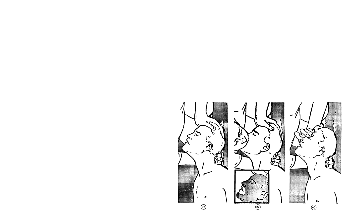
z Method of mouth-to-mouth respiration by raising head
Fig. 1 Mouth-to mouth respiration
(1) Raise the victim's head. Support his
forehead with one of your hand and his
neck with the other hand.ձ
When you tilt his head backward, the
victim, in most cases, opens his mouth
to the air. This makes mouth-to mouth
respiration easy.
(2) Cover his mouth as widely as possible
with yours and press your cheek against
his noseղ
Or, pinch his nostrils with your fingers to
prevent air from leaking.ճ
(3) Blow into his lungs. Continue blowing
into his mouth until his breast swells.
Blow into his mouth as quickly as
possible for the first 10 times.
FIRST-AID TREATMENTS
iv
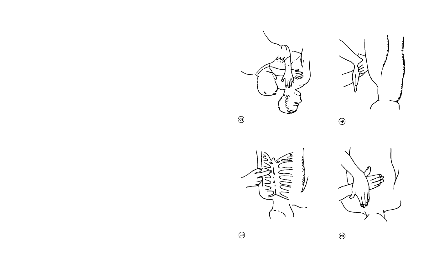
When both pulse and breathing have stopped
Perform the (Cardiac massage) Fig. 2 and (Mouth-to-mouth respiration) Fig. 1
When no pulse has come not to be felt, his pupils are open and no heartbeat is heard,
cardiac arrest is supposed to have occurred and artificial respiration must be performed.
1Place your both hands, one hand on the other, on the lower one third area of
his breastbone and compress his breast with your elbows applying your
weight on his breast so that it is dented about 2cm (Repeat compressing his
breast 50 times or so a minutes). (Cardiac massage)
2In case of one rescuer, Repeat cardiac massages about 15 times and blow
into his mouth 2 times quickly, and repeat this combination.
In case of two rescuers, one person repeats cardiac massages 15 times
while the other person blow into his mouth twice, and they shall repeat this
combination. (Perform the cardiac massage and mouth-to-mouth respiration)
3Examine his pupils and his pulse sometimes. When the both have returned
to normal, stop the artificial respiration, serve him with a cup of hot coffee or
tea and keep him warm and calm while watching him carefully. (Never give
him alcoholic drinks.) Commit the victim to a medical specialist depending on
his condition. To let him recover from the mental shock, it is necessary for
persons concerned to understand his situations and the necessary treatment.
Fig. 2 Cardiac massage

PREFACE
v
PREFACE
Thank you very much for purchasing the JRC marine radar equipment, JMA-3300 series.
This equipment is a marine radar equipment designed to obtain safe operation of marine
ships. This equipment consists of a scanner unit and a display unit as its main units.
zBefore operating the equipment, be sure to read this instruction manual carefully for
correct operation.
zMaintain this instruction manual so that operators can refer to it at anytime.
Refer to this manual when any inconvenience or defect occurs.
BEFORE OPERATION
vi
BEFORE OPERATION
Pictorial Indication
Various pictorial indications are included in this manual and are shown on these
equipment so that you can operate them safety and correctly and prevent any danger to
you and/or to other persons and any damage to your property during operation. Such
indications and their meanings are as follows.
Understand them before you read this manual.
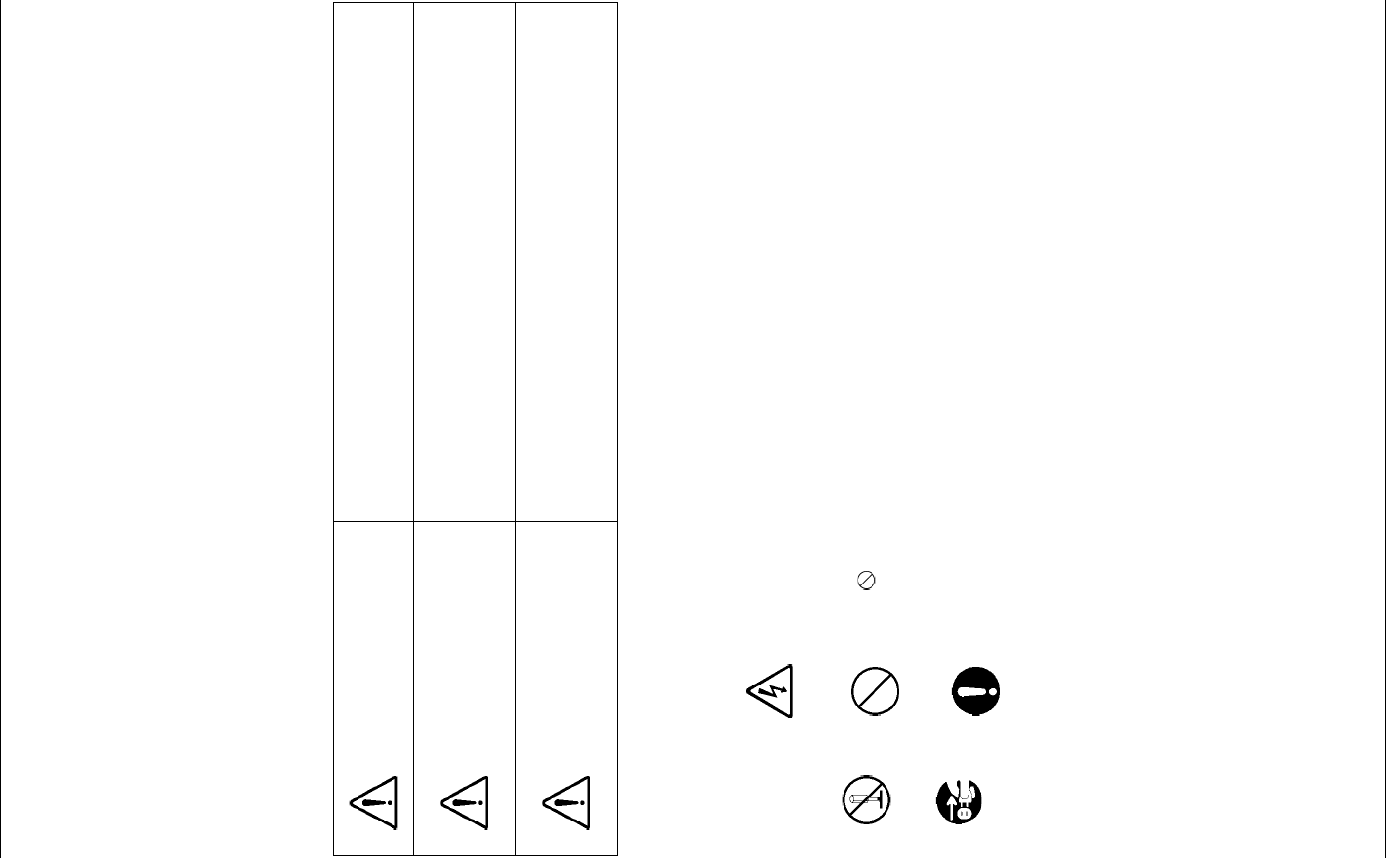
DANGER This indication is shown where incorrect equipment
operation due to negligence may cause death or serious
injuries.
WARNING
This indication is shown where any person is supposed to
be in danger of being killed or seriously injured if this
indication is neglected and these equipments are not
operated correctly.
CAUTION
This indication is shown where any person is supposed to
be injured or any property damage is supposed to occur if
this indication is neglected and these equipments are not
operated correctly.
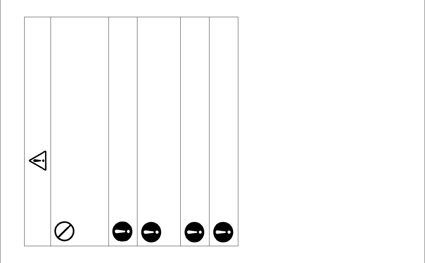
Examples of Pictorial Indication
Electric
Shock
The ڹ mark represents CAUTION (including DANGER and
WARNING).
Detailed contents of CAUTION ("Electric Shock" in the example on the
left.) is shown in the mark.
Disassembling
Prohibited Prohibited
The mark represents prohibition.
Detailed contents of the prohibited action ("Disassembling Prohibited" in
the example on the left.) is shown in the mark.
Disconnect
the power
plug
Instruction
The mark represents instruction.
Detailed contents of the instruction ("Disconnect the power plug" in the
example on the left.) is shown in the mark.
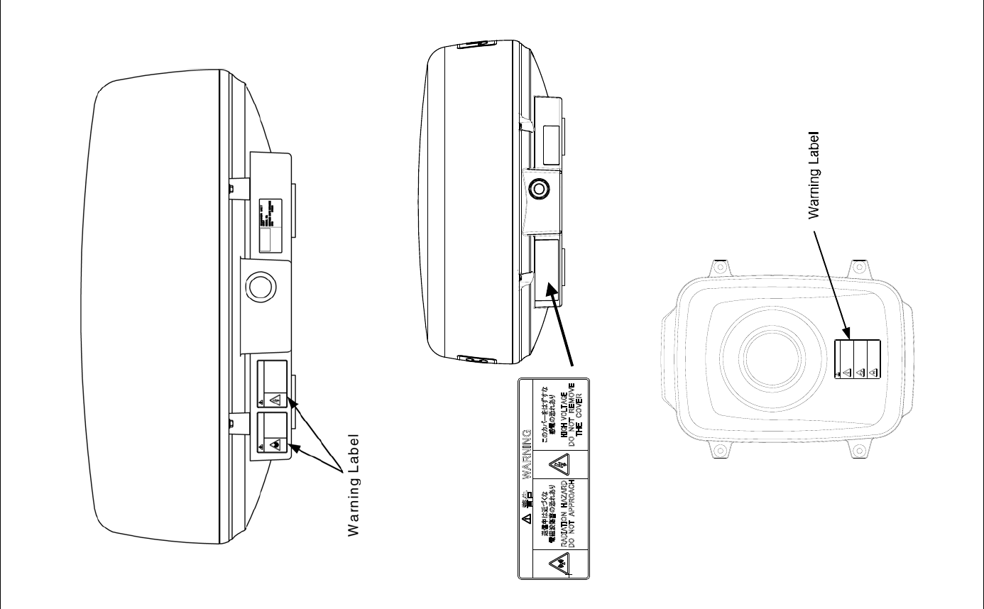
Warning Label
There is a warning label on the equipment.
Do not try to remove, break or modify the label.
PRECAUTIONS
vii
PRECAUTIONS
DANGER
Never carry out internal inspection or repair work of the equipment
by users.
Inspection or repair work by unauthorized personnel may result in
fire hazard or electric shock.
For inspection and repair work of equipment components, consult
with our branch office, branch shop, sales office, or our distributor
in your district.
When conducting maintenance, make sure to turn the main power
off.
Failure to comply may result in electrocution.
Turn off the main power before cleaning the equipment. Especially
when a rectifier is used, make sure to turn it off since voltage is
still output from the rectifier even after the radar is turned off.
Failure to comply may result in equipment failure, electric shock or
serious injury.
When conducting maintenance work on the antenna, make sure to
turn its main power off.
Failure to comply may result in electrocution or injuries.
Make sure to turn on the antenna operation switch.
Failure to comply may result in injuries caused by physical contact
with the rotating antenna.
PRECAUTIONS
viii
WARNING
Never directly touch the internal components of the antenna,
receiver/transceiver, or indicator.
Direct contact with these high-voltage components may cause
electrocution. For maintenance, inspection, or adjustment of
equipment components, consult with our branch office, branch
shop, sales office, or our distributor in your district.
Do not get close to the radiant section of the antenna. It is a
rotating part, and it may cause injuries if it suddenly starts rotating
and consequently hits the body.
It is recommended that the radiant section be installed at a high
place such as on the roof of the wheelhouse, on the flying bridge,
on the trestle, or on the radar mast so that no one can get close to
it. When any work must be done on the antenna, make sure to turn
the antenna switch off.
Microwave radiation level:
Keep away from a scanner when it is transmitting.
The high level of microwave is radiated from the front face of the
scanner specified below. The microwave exposure at close range
could result in injuries (especially of the eyes).
50W/m210W/m22.5W/m2
NKE-2103 n/a 26cm 123cm
Make sure to install the antenna at a place higher than human
height.
Direct exposure to electromagnetic waves at close range will have
adverse effects on the human body.
Direct exposure to electromagnetic waves at close range will have
adverse effects on the human body. When it is necessary to get
close to the antenna for maintenance or inspection purposes,
make sure to turn the indicator power switch to "OFF" or "STBY."
Direct exposure to electromagnetic waves at close range will have
adverse effects on the human body.
When conducting maintenance work, make sure to turn off the
power and unplug the power connector J1 of the display unit so
that the power supply to the equipment is completely cut off.
Some equipment components can carry electrical current even
after the power switch is turned off, and conducting maintenance
work without unplugging the power connector may result in
electrocution, equipment failure, or accidents.
Do not touch the radiator. Even if the power is turned off, the
radiator may be rotated by the wind.
PRECAUTIONS
ix
CAUTION
A malfunction may occur if the power in the ship is
instantaneously interrupted during operation of the radar. In this
case, the power should be turned on again.
Always use the automatic tuning mode.
Use the manual tuning mode only when the automatic tuning
mode does not provide the best tuning state due to deterioration
of magnetron for example.
If sensitivity is set too high, unnecessary signals such as noises in
the receiver and false echoes increase to lower target visibility.
At the same time, if sensitivity is set too low, detection of targets
such as ships and dangerous objects may be hindered.
Therefore, sensitivity must always be set to an optimal level.
When using the sea clutter suppression function, never set the
suppression level too high canceling out all image noises from the
sea surface at close range. Detection of not only echoes from
waves but also targets such as other ships or dangerous objects
will become inhibited.
When using the sea clutter suppression function, make sure to
choose the most appropriate image noise suppression level.
When using the sea clutter suppression function, never set the
suppression level too high canceling out all image noises from the
rain or snow at close range. Detection of not only echoes from the
rain or snow but also targets such as other ships or dangerous
objects will become inhibited.
When using the sea clutter suppression function, make sure to
choose the most appropriate image noise suppression level.
Use the radar only as a navigation aid.
The final navigation decision must always be made by the operator
him/herself.
Making the final navigation decision based only on the radar
display may cause accidents such as collisions or running
aground.
Use the target tracking function (TT) only as a navigation aid. The
final navigation decision must always be made by the operator
him/herself.
Making the final navigation decision based only on the target
tracking function (TT) information may cause accidents.
The target tracking function (TT) information such as vector, target
numerical data, and alarms may contain some errors. Also, targets
that are not detected by the radar cannot be acquired or tracked.
Making the final navigation decision based only on the radar
display may cause accidents such as collisions or running
aground.
PRECAUTIONS
x
CAUTION
Target Tracking Function Test is provided to test if the target
tracking function is operating normally. Thus, do not use the
function except when you test the target tracking function.
Note especially that, if this function is used during actual
navigation, simulated targets are displayed and may become
confused with other actual targets. Therefore, never use this
function during actual navigation.
When a large value is set as an association condition, a tracked
target near an AIS target is identified as the AIS target and may
thus disappear from the display.
For example, when a pilot vessel equipped with the AIS function (a
small target which is not a tracked target) goes near a cargo vessel
which is a tracked target without the AIS function, the tracked
target symbol for the cargo vessel may disappear.
Since these alarms may include some errors depending on the
target tracking conditions, the navigation officer himself should
make the final decision for ship operations such as collision
avoidance.
Making the final navigation decision based only on the alarm may
cause accidents such as collisions.
When setting an automatic acquisition zone, make sure to properly
adjust gain, sea-surface reflection suppression level, and
rain/snow reflection suppression level so that the optimal target
images are always on the radar screen. The automatic acquisition
zone alarm will not be activated for targets undetected by the
radar, and it may result in accidents such as collisions.
Any adjustments must be made by specialized service personnel.
Incorrect settings may result in unstable operation.
Do not make any adjustments during navigation. Failure to comply
may result in adverse effects on the radar function which may lead
to accidents or equipment failure.
Any adjustments must be made by specialized service personnel.
Failure to comply may result in accidents or equipment failure.
Make sure to shut off the main power before replacing parts.
Failure to comply may result in electrocution or equipment failure.
When replacing magnetrons, make sure to shut off the main power
and let the equipment stand for more than 5 minutes to discharge
the high-voltage circuit.
Failure to comply may result in electrocution.
PRECAUTIONS
xi
CAUTION
Make sure to take off your watch when your hand must get close
to the magnetron.
Failure to comply may result in damage to the watch since the
magnetron is a strong magnet.
Make sure that two or more staff member work together when
replacing the LCD.
If only one person attempts to replace the LCD, he/she may drop it
and become injured.
Do not directly touch the inverter circuit of the LCD display with a
bare hand since high voltage temporarily remains in the circuit
even after the main power is shut off.
Failure to comply may result in electrocution.
When cleaning the display screen, do not wipe it too strongly with
a dry cloth. Also, do not use gasoline or thinner to clean the
screen.
Failure to comply will result in damage to the screen surface.
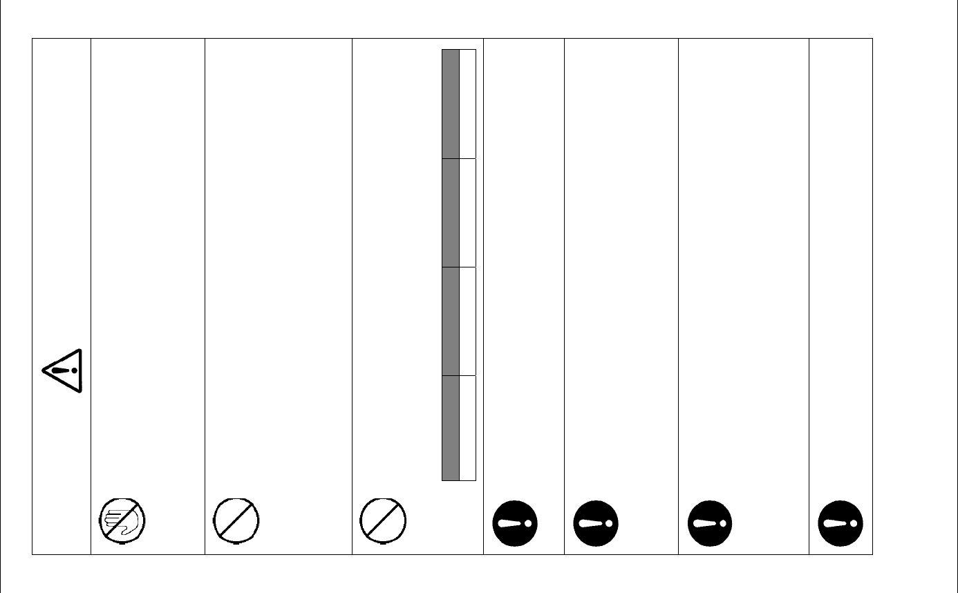
WARNING LABEL MOUNTING POINT
xii
WARNING LABEL MOUNTING POINT
NKE-2042 Scanner Unit
NKE-2043 Scanner Unit
NKE-2062/HS Scanner Unit
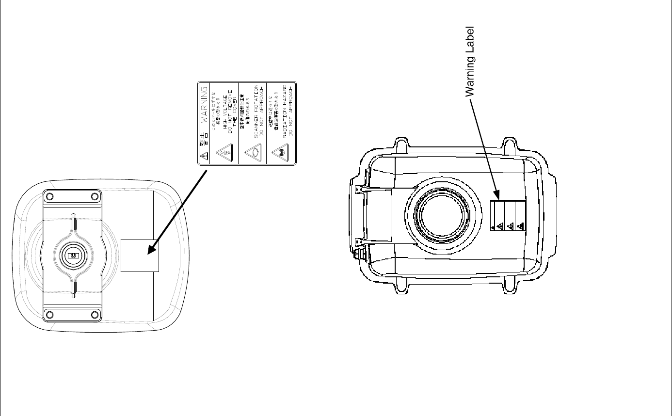
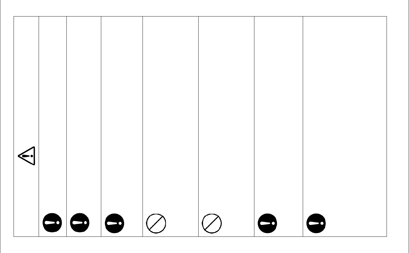
WARNING LABEL MOUNTING POINT
xiii
NKE-2063/HS Scanner Unit
NKE-2103-4/6/4HS/6HS Scanner Unit
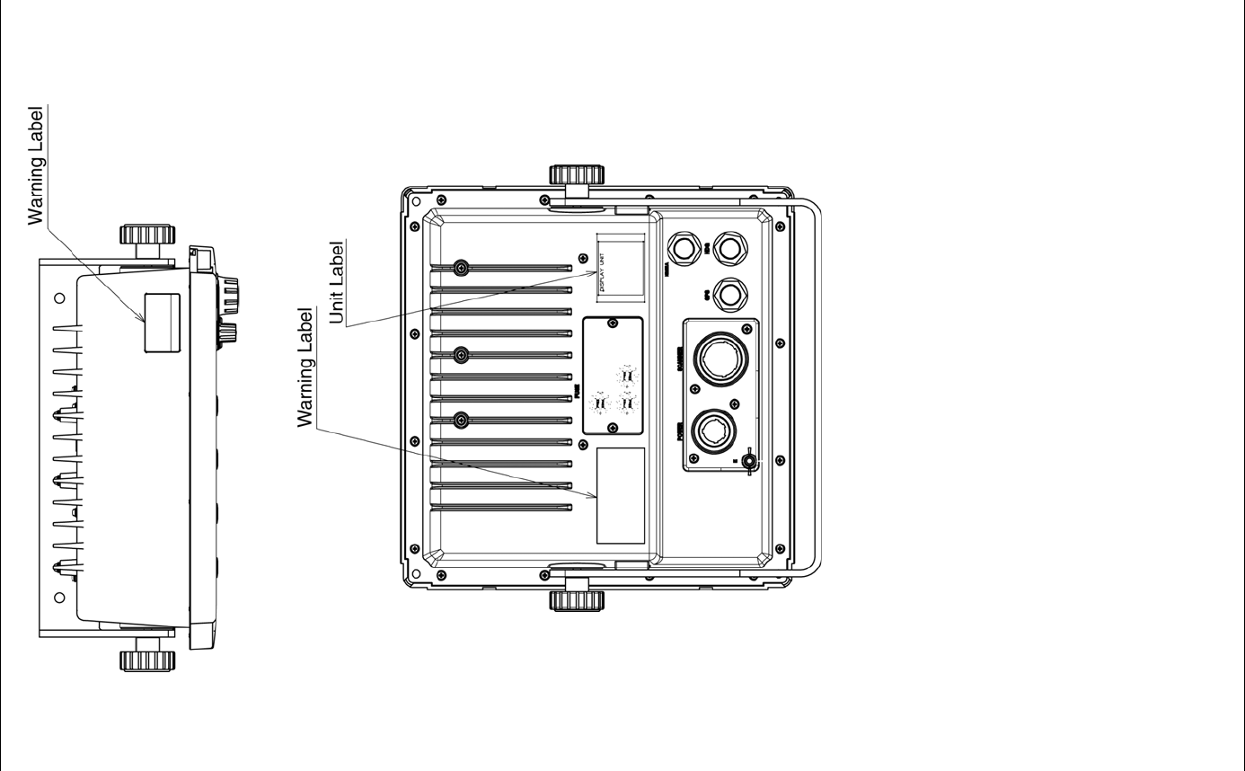
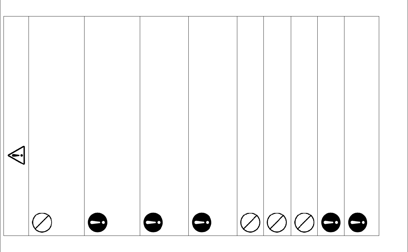
WARNING LABEL MOUNTING POINT
xiv
NCD-2182 Display Unit
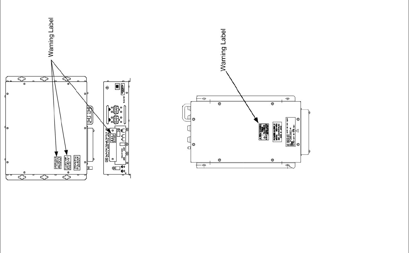
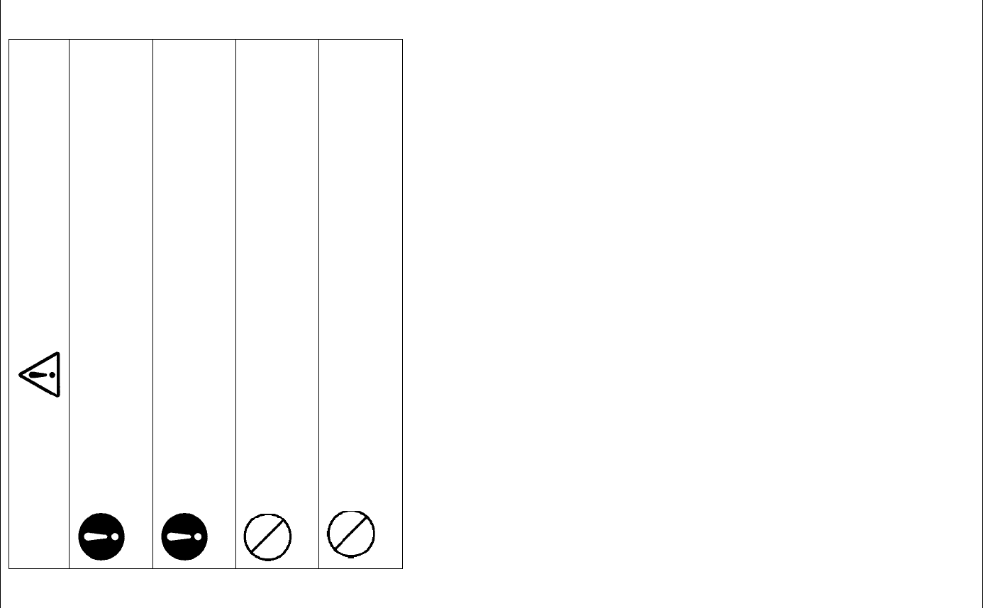
WARNING LABEL MOUNTING POINT
xv
NBA-5111 Power Supply
NBD-865 Rectifier unit
EQUIPMENT APPEARANCE
xvi
EQUIPMENT APPEARANCE
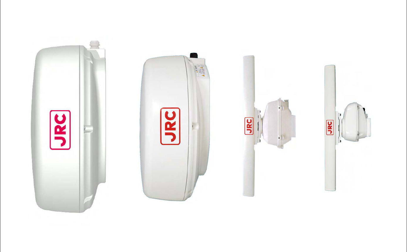
Scanner Unit Type NKE-2042 (2 feet)
Scanner Unit Type NKE-2043 (2 feet)
Scanner Unit Type NKE-2062/HS (3.9 feet)
Scanner Unit Type NKE-2063/HS (3.9 feet)
EQUIPMENT APPEARANCE
xvii
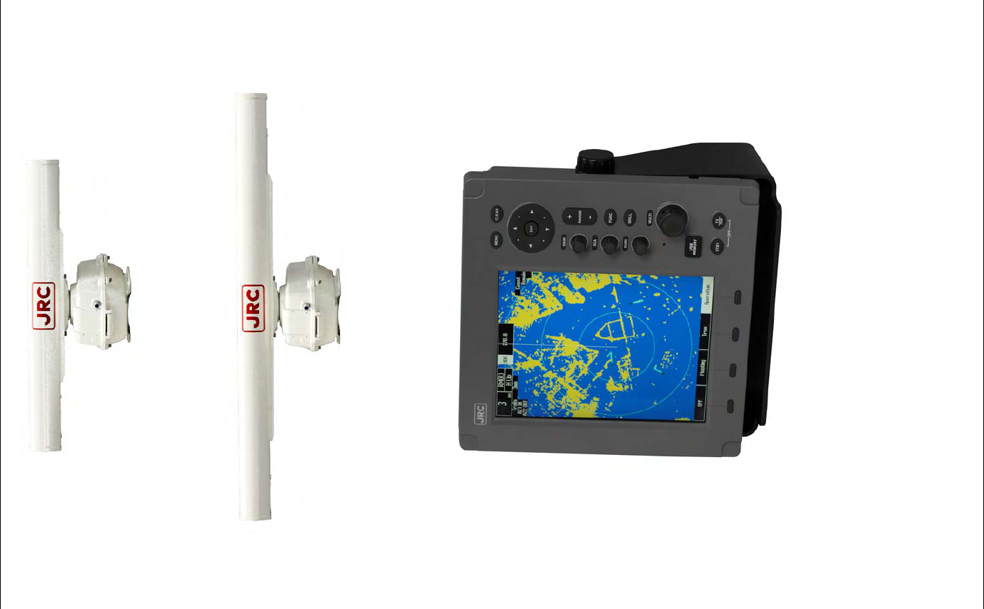
Scanner Unit Type NKE-2103-4/4HS (4 feet)
Scanner Unit Type NKE-2103-6/6HS (6 feet)
NCD-2182 Display Unit

CONTENTS
xviii
CONTENTS
PREFACE .................................................................................v
BEFORE OPERATION .............................................................vi
PRECAUTIONS .......................................................................vii
WARNING LABEL MOUNTING POINT ..................................xii
EQUIPMENT APPEARANCE.................................................xvi
GLOSSARY ..........................................................................xxiii
Chapter 1 GENERAL AND EQUIPMENT COMPOSITION
............................................................................. 1-1
1.1 FUNCTIONS............................................................................................................................. 1-1
1.2 FEATURES .............................................................................................................................. 1-2
1.3 CONFIGURATION ................................................................................................................... 1-3
1.4 EXTERIOR DRAWINGS.......................................................................................................... 1-7
1.5 GENERAL SYSTEM DIAGRAMS ......................................................................................... 1-15
Chapter 2 OPERATIONS...................................................... 2-1
2.1 SCREEN DISPLAY .................................................................................................................. 2-1
2.2 PANEL ...................................................................................................................................... 2-2
2.3 POWER ON/OFF ..................................................................................................................... 2-4
2.4 SENSITIVITY ADJUSTMENT ................................................................................................. 2-6
2.5 SEA CLUTTER SUPPRESSION............................................................................................. 2-8
2.6 RAIN/SNOW CLUTTER SUPPRESSION ............................................................................ 2-11
2.7 SOFT KEY OPERATION....................................................................................................... 2-14
2.7.1 MEASURING TARGET BEARING (EBL)...................................................................... 2-22
2.7.2 MEASURING RANGE TO TARGET (VRM).................................................................. 2-24
2.7.3 DISPLAYING PARALLEL CURSORS........................................................................... 2-26
2.7.4 SETTING VECTORS...................................................................................................... 2-29
2.7.5 DISPLAYING OTHER SHIP'S TRACKS (RADAR TRAILS)......................................... 2-32
2.7.6 AIS OPERATIONS ......................................................................................................... 2-34
2.7.7 TT OPERATIONS........................................................................................................... 2-39

CONTENTS
xix
2.7.8 DISPLAYING THE RADAR ALARM
AND AUTOMATIC ACQUISITION OPERATIONS ...................................................... 2-47
2.7.9 SETTING DISPLAY BRILLIANCE AND DISPLAY COLOR ......................................... 2-53
2.7.10 ADJUSTING SCANNER ................................................................................................ 2-54
2.7.11 SETTING DISPLAY SCREEN ....................................................................................... 2-56
2.7.12 SWITCHING TO TRUE/RELATIVE MOTION DISPLAY MODE .................................. 2-60
2.7.13 SWITCHING BEARING DISPLAY MODE..................................................................... 2-62
2.7.14 SELECTING TRANSMITTER PULSE LENGTH........................................................... 2-64
2.7.15 MOVING OWN SHIP’S DISPLAY POSITION............................................................... 2-66
2.7.16 SETTING SYMBOL DISPLAY ....................................................................................... 2-67
2.7.17 SETTING MOB ............................................................................................................... 2-68
2.7.18 MARKING........................................................................................................................ 2-68
2.7.19 USING LINES ................................................................................................................. 2-70
2.7.20 DISPLAYING OWN SHIP'S TRACK.............................................................................. 2-71
2.7.21 USING EVENT MARKS ................................................................................................. 2-72
2.7.22 SETTING AIS FILTER.................................................................................................... 2-73
2.7.23 USING TLL TX ................................................................................................................ 2-74
2.8 BASIC MENU OPERATIONS................................................................................................ 2-75
2.9 RADAR ECHO SETTINGS.................................................................................................... 2-79
2.9.1 SETTING RADAR INTERFERENCE REJECTION ...................................................... 2-79
2.9.2 SETTING FOR ENHANCING TARGETS...................................................................... 2-80
2.9.3 PROCESS....................................................................................................................... 2-81
2.9.4 ZOOMING ....................................................................................................................... 2-82
2.9.5 VIDEO LATITUDE .......................................................................................................... 2-82
2.9.6 VIDEO NOISE REJECTION........................................................................................... 2-83
2.10 RADAR TRAIL LENGTH SETTING ...................................................................................... 2-84
2.11 MARKER SETTING ............................................................................................................... 2-86
2.11.1 SETTING OPERATIONS FOR EBLS (ELECTRONIC BEARING LINES)................... 2-86
2.11.2 SETTING OPERATIONS FOR PARALLEL CURSORS............................................... 2-88
2.11.3 SETTING CURSORS ..................................................................................................... 2-92
2.11.4 SETTING RANGE RINGS.............................................................................................. 2-93
2.12 DISPLAY COLOR SETTING ................................................................................................. 2-94
2.13 CONTROL SETTING........................................................................................................... 2-107
2.13.1 DISPLAYING TRUE/RELATIVE MOTION .................................................................. 2-107
2.13.2 SETTING USER KEYS ................................................................................................ 2-108
2.13.3 ADJUSTING BUZZER VOLUME................................................................................. 2-110
2.14 FUNCTION KEY SETTINGS............................................................................................... 2-112
2.14.1 FUNCTION KEY OPERATIONS.................................................................................. 2-112
2.14.2 FUNCTION SETTING ITEMS ...................................................................................... 2-114
2.14.3 OVERVIEW OF FUNCTION SETTING ITEM OPERATIONS.................................... 2-115

CONTENTS
xx
2.15 SETTING TT/AIS.................................................................................................................. 2-120
2.15.1 COLLISION AVOIDANCE ............................................................................................ 2-120
2.15.2 PREPARATION ............................................................................................................ 2-123
2.15.3 SETTING TARGET NUMBER DISPLAY..................................................................... 2-125
2.15.4 SETTING TARGET NUMBER ALLOCATION............................................................. 2-126
2.15.5 SETTING AIS ALARM.................................................................................................. 2-127
2.15.6 SETTING AIS DISPLAY TARGET............................................................................... 2-128
2.15.7 SETTING AIS DESTINATION SHIP (DirecTrakTM) ..................................................... 2-128
2.15.8 SETTING AIS RETRIEVED VESSEL.......................................................................... 2-129
2.15.9 SETTING AIS FILTER.................................................................................................. 2-130
2.15.10 FILE OPERATION ........................................................................................................ 2-130
2.16 SETTING DETECTION LEVELS OF RADAR ALARM ...................................................... 2-134
2.17 PLOTTER UNIT ................................................................................................................... 2-135
2.17.1 DISPLAYING WAYPOINT MARKS ............................................................................. 2-135
2.17.2 SETTING MARK FUNCTIONS .................................................................................... 2-136
2.17.3 SETTING LINE FUNCTIONS....................................................................................... 2-140
2.17.4 DISPLAYING OWN SHIP'S TRACK............................................................................ 2-144
2.17.5 FILE OPERATIONS...................................................................................................... 2-146
2.18 SETTING TIMED TX............................................................................................................ 2-153
Chapter 3 TRUE AND FALSE ECHOES ON DISPLAY
............................................................................. 3-1
3.1 RADAR WAVE WITH THE HORIZON.................................................................................... 3-1
3.2 REFLECTION FROM TARGET .............................................................................................. 3-3
3.3 SEA CLUTTER AND RAIN AND SNOW CLUTTER.............................................................. 3-4
3.3.1 SEA CLUTTER ................................................................................................................. 3-4
3.3.2 RAIN AND SNOW CLUTTER .......................................................................................... 3-4
3.3.3 COPING WITH SEA CLUTTER AND RAIN AND SNOW CLUTTER ............................ 3-4
3.4 FALSE ECHOES...................................................................................................................... 3-5
3.4.1 SHADOW .......................................................................................................................... 3-5
3.4.2 SIDE LOBE EFFECT........................................................................................................ 3-5
3.4.3 FALSE ECHO BY SECONDARY REFLECTION............................................................ 3-5
3.4.4 FALSE ECHO BY MULTIPLE REFLECTION ................................................................. 3-6
3.4.5 SECOND TIME ECHOES ................................................................................................ 3-6
3.4.6 RADAR INTERFERENCE................................................................................................ 3-7
3.5 DISPLAY OF RADAR TRANSPONDER (SART) ................................................................... 3-8

CONTENTS
xxi
Chapter 4 MAINTENANCE................................................... 4-1
4.1 ROUTINE MAINTENANCE ..................................................................................................... 4-1
4.2 MAINTENANCE ON EACH UNIT ........................................................................................... 4-2
4.2.1 SCANNER UNIT NKE-2042, 2043, 2062/HS, 2063/HS, 2103-4/4HS/6/6HS
.......................................................................................................................................... 4-2
4.2.2 DISPLAY UNIT NCD-2182............................................................................................... 4-5
4.3 PERFORMANCE CHECK ....................................................................................................... 4-6
4.3.1 TEST MENU ..................................................................................................................... 4-7
4.3.2 SYSTEM INFORMATION ................................................................................................ 4-7
4.3.3 SYSTEM TIME.................................................................................................................. 4-8
4.3.4 SCANNER INFORMATION ............................................................................................. 4-8
4.3.5 HARDWARE INFORMATION.......................................................................................... 4-9
4.3.6 ERROR LOG..................................................................................................................... 4-9
4.3.7 LINE MONITOR .............................................................................................................. 4-11
4.3.8 SELF TEST ..................................................................................................................... 4-12
4.4 REPLACEMENT OF MAJOR PARTS .................................................................................. 4-17
4.5 FAULT FINDING .................................................................................................................... 4-19
4.5.1 LIST OF ALARMS AND OTHER INDICATIONS .......................................................... 4-19
4.5.2 FUSE CHECKING .......................................................................................................... 4-28
4.6 TROUBLE SHOOTING.......................................................................................................... 4-30
4.6.1 INCLUDED ACCESSORIES.......................................................................................... 4-30
4.6.2 SPECIAL PARTS............................................................................................................ 4-33
4.6.3 CIRCUIT BLOCK TO BE REPAIRED............................................................................ 4-34
Chapter 5 AFTER-SALES SERVICE ................................... 5-1
5.1 KEEPING PERIOD OF MAINTENANCE PARTS....................................................................... 5-1
5.2 WHEN YOU REQUEST FOR REPAIR................................................................................... 5-1
5.3 RECOMMENDED MAINTENANCE........................................................................................ 5-1
Chapter 6 DISPOSAL ........................................................... 6-1
6.1 DISPOSAL OF THE UNIT ....................................................................................................... 6-1
6.2 DISPOSAL OF USED MAGNETRON..................................................................................... 6-2
6.3 CHINA RoHS............................................................................................................................ 6-2

CONTENTS
xxii
Chapter 7 SPECIFICATIONS ............................................... 7-1
7.1 GENERAL SPECIFICATIONS ................................................................................................ 7-1
7.2 SCANNER ................................................................................................................................ 7-3
7.2.1 NKE-2042.......................................................................................................................... 7-3
7.2.2 NKE-2043.......................................................................................................................... 7-4
7.2.3 NKE-2062/HS.................................................................................................................... 7-5
7.2.4 NKE-2063/HS.................................................................................................................... 7-7
7.2.5 NKE-2103-4/6/4HS/6HS................................................................................................... 7-9
7.3 DISPLAY UNIT....................................................................................................................... 7-11
7.3.1 INTEGRATED DISPLAY UNIT (NCD-2182) ................................................................. 7-11
7.3.2 OPERATION PANEL...................................................................................................... 7-13
7.3.3 AIS FUNCTION............................................................................................................... 7-13
7.3.4 TT FUNCTION ................................................................................................................ 7-14
7.4 INPUT/OUTPUT SIGNAL ...................................................................................................... 7-15
7.4.1 INPUT ENABLE SIGNAL ............................................................................................... 7-15
7.4.2 OUTPUT ENABLE SIGNAL ........................................................................................... 7-15
7.5 STANDARD CONFIGURATION ........................................................................................... 7-16
APPENDIX
INDEX

GLOSSARY
xxiii
GLOSSARY
This section describes the main terms used for this equipment and general related
maritime terms.
A
AZ Acquisition/Activation zone
A zone set up by the operator in which the system should automatically acquire radar
targets and activate reported AIS targets when entering the zone.
Activated target A target representing the automatic or manual activation of a sleeping target for the
display of additional information.
AIS Automatic Identification System
A system which enables ships and shore stations to obtain identifying and navigation
information about other ships at sea, using an automated transponder.
Anti-clutter rain Rain/snow clutter suppression.
Anti-clutter sea Sea clutter suppression.
AZI AZImuth stabilization mode
B
BCR/BCT Bow Crossing Range and Bow Crossing Time
C
C up Course up
Own ship’s course is pointed to the top center of the radar display.
CCRP The Consistent Common Reference Point
A location on own ship, to which all horizontal measurements such as target range,
bearing, relative course, relative speed, CPA or TCPA are referenced, typically the
conning position of the bridge.
Clutter Unwanted reflections on a radar screen, from sea surface, rain or snow.
COG Course Over Ground
The direction of the ship's movement relative to the earth, measured on board the ship,
expressed in angular units from true north
CORREL Correlation
CPA/TCPA The distance to the Closest Point of Approach and Time to the Closest Point of
Approach. Limits are set by the operator and are related to own ship.
CTW Course Through Water
The direction of the ship's movement through the water
D
DRIFT The current velocity for manual correction or the current speed on the horizontal axis of
the 2-axis log is displayed.

GLOSSARY
xxiv
E
EBL Electronic Bearing Line
An electronic bearing line originated from own ship’s position.
ENH Enhance
ETA Estimated Time of Arrival
G
Ground stabilization A display mode in which speed and course information are referred to the ground, using
ground track input data.
H
HDG Heading
The horizontal direction that the bow of a ship is pointing at any instant, expressed in
angular units from a reference direction .
HL Heading line
A graphic line on a radar presentation drawn from the consistent common reference
point to the bearing scale to indicate the heading of the ship
H up Head up
Own ship’s heading line is always pointed to the top center of the radar display.
I
IR Radar Interference Rejecter
L
Lost AIS target A target symbol representing the last valid position of an AIS target before the reception
of its data was lost, or its last dead-reckoned position.
Lost tracked target One for which target information is no longer available due to poor, lost or obscured
signals.
LP Long Pulse
M
MMSI Maritime Mobile Service Identity
MOB Man OverBoard
MP Medium Pulse
N
NM 1NM=1852m
NSK North Stabilization Kit
N up North up
The north is always pointed to the top center of the radar display.
O
Own track Display function of own ship’s track

GLOSSARY
xxv
P
PI Parallel Index line
Past positions Equally time-spaced past position marks of a tracked or AIS target and own ship.
POSN Position
PRF Pulse Repetition Frequency
The number of radar pulses transmitted each second.
PROC Process
Radar signal processing function
R
Radar beacon A navigation aid which responds to the radar transmission by generating a radar signal
to identify its position and identity
Radar cross-section Radar cross-section of a target determines the power density returned to the radar for a
particular power density incident on the target
Range Rings A set of concentric circles labeled by distance from CCRP.
Reference target A symbol indicating that the associated tracked stationary target is used as a speed
reference for the ground stabilization
Relative course The direction of motion of a target relative to own ship motion
Relative speed The speed of a target relative to own ship’s speed data
Relative vector A predicted movement of a target relative to own ship’s motion
RM Relative Motion
A display on which the position of own ship remains fixed, and all targets move relative
to own ship.
RM(R) Relative Motion. Relative Trails.
RM(T) Relative Motion. True Trails.
ROT Rate Of Turn
Change of heading per time unit.
Route A set of waypoints.
RR Range Rings

GLOSSARY
xxvi
S
SART Search And Rescue Transponder
Radar transponder capable of operating in the 9GHz band
Sea stabilization A display mode in which speed and course information are referred to the sea.
Sea state Status of the sea condition due to the weather environment, expressed as a sea state 0 for
flat conditions with minimal wind, to sea state 8 for very rough sea conditions.
SET The current direction for manual correction or the current speed on the horizontal axis of
the 2-axis log is displayed.
Sleeping AIS target A target indicating the presence and orientation of a vessel equipped with AIS in a
certain location.
SOG Speed Over the Ground
The speed of the ship relative to the earth, measured on board of the ship.
SP Short Pulse
STAB Stabilization
STW Speed Through Water
The speed of the ship relative to the water surface.
T
TCPA Time to Closest Point of Approach to own ship
Test target Radar target of known characteristics used for test requirement
TM True Motion
A display across which own ship moves with its own true motion.
Trails Display Radar Trails (Other Ships' Trails)
True course The direction of motion relative to ground or to sea, of a target expressed as an angular
displacement from north
True speed The speed of a target relative to ground, or to sea
True vector A vector representing the predicted true motion of a target, showing course and speed
with reference to the ground or sea
TT Target Tracking.
A computer process of observing the sequential changes in the position of a radar target
in order to establish its motion. Such a target is a Tracked Target.
TTG Time To Go.
Time to next waypoint.
TXRX Transceiver Unit

GLOSSARY
xxvii
U
UTC Universal Time Coordinated.
The international standard of time, kept by atomic clocks around the world.
V
VRM Variable Range Marker
An adjustable range ring used to measure the distance to a target.
W
Waypoint A geographical location on a route indicating an event.

GLOSSARY
xxviii

Chapter 1
GENERAL AND EQUIPMENT COMPOSITION
1.1
FUNCTIONS
1-1
INSTRUCTION MANUAL
1
Chapter 1
GENERAL AND EQUIPMENT
COMPOSITION
1.1 FUNCTIONS
This equipment is a marine radar equipment consisting of a scanner unit and an
integrated color LCD display unit.
Function of This System
ySensitivity adjustment
ySea clutter suppression
yRain/snow clutter suppression
yIR (Interference rejection)
yBearing and range measurement using a cursor, fixed/variable range markers, and
electronic bearing line
yOwn ship's track display
yNAV line and marker displays
yTM (True Motion) presentation
ySelf-diagnostic
yTT (manual and automatic target acquisition/automatic tracking, vector and trail
displays and alarm displays)
yAIS

Chapter 1
GENERAL AND EQUIPMENT COMPOSITION
1.2
FEATURES
1-2
1.2 FEATURES
Equipping a Bright and Easy-to-see LCD Screen
10.4-inch color LCD of 640X480 pixels (VGA) is equipped.
Easy Operation with the Soft keys and the Multi Control
Simple and easy operations are provided so that you can operate without this instruction
manual.
Target Detection by Latest Signal Processing Technology
The system employs a signal processing technology of DSP to eliminate undesired
clutter, thus improving the target detection.
TT and AIS functions as Standard Equipment
High performance target tracking function which can automatically track targets (up to
10 targets) and AIS target display function (up to 50 targets) are provided.
Chapter 1
GENERAL AND EQUIPMENT COMPOSITION
1.3
CONFIGURATION
1-3
INSTRUCTION MANUAL
1
1.3 CONFIGURATION
Radar Configuration and Ship's Mains
RADAR MODEL Scanner Display Unit SHIP'S MAINS
JMA-3314 NKE-2042
JMA-3334 NKE-2043
JMA-3316 NKE-2062
12/24 VDC
JMA-3316HS NKE-2062HS 24 VDC
JMA-3336 NKE-2063 12/24 VDC
JMA-3336HS NKE-2063HS
JMA-3340-4 NKE-2103-4
JMA-3340-4HS NKE-2103-4HS
JMA-3340-6 NKE-2103-6
JMA-3340-6HS NKE-2103-6HS
NCD-2182
24 VDC
Scanners and Transmitted Output Powers
SCANNER TYPE
TRANSMITTED
OUTPUT
POWER
BAND RATE OF
ROTATION
JMA-3314
JMA-3334
620mm Radome 4kW 27 rpm
JMA-3316 27 rpm
JMA-3316HS 48 rpm
JMA-3336 27 rpm
JMA-3336HS
3.9 FT SLOT ANTENNA 6kW
48 rpm
JMA-3340-4 27 rpm
JMA-3340-4HS
4 FT SLOT ANTENNA
48 rpm
JMA-3340-6 27 rpm
JMA-3340-6HS
6 FT SLOT ANTENNA
10 kW
X
48 rpm
Reference:
1 An optional rectifier NBA-5111 or NBD-865 is necessary for using Ship's Mains
100-120/220-240 VAC, 50/60Hz, 1I.
2 If connecting to gyro with synchro signal output or step signal output, optional NSK unit
NCT-4106A is required.

Chapter 1
GENERAL AND EQUIPMENT COMPOSITION
1.3
CONFIGURATION
1-4
Supplied accessories
PRODUCT NAME/MODEL QUANTITY JRC CODE REMARKS
Instruction manual
7ZPRD0787 1 7ZPRD0787 This manual
Installation manual
7ZPRD0789 1 7ZPRD0789
Quick manual
7ZPRD0793 1 7ZPRD0793
Power cord
H-CFQ-5436-5 1 CFQ-5436-5
5 m
RoHS compliance
Included accessories
PRODUCT NAME/MODEL QUANTITY JRC CODE REMARKS
Fuse
ST4-6.3AN1 4
Scanner NKE-2042(DC12V)
For the modulator(F2)
JRC CODE: 5ZFCA00051
1 for installation
3 for spares
Fuse
ST4-3.15AN1 4
7ZXRD0012
Scanner NKE-2042(DC24V)
For the modulator(F2)
JRC CODE: 5ZFCA00047
1 for installation
3 for spares
Fuse
ST4-6.3AN1 4
Scanner NKE-2043(DC12V)
For the compound modulator(F2)
JRC CODE: 5ZFCA00051
1 for installation
3 for spares
Fuse
ST4-3.15AN1 4
7ZXRD0012
Scanner NKE-2043(DC24V)
For the compound modulator(F2)
JRC CODE: 5ZFCA00047
1 for installation
3 for spares
Fuse
ST4-6.3AN1 4
Scanner NKE-2062(DC12V)
For the modulator(F2)
JRC CODE: 5ZFCA00051
1 for installation
3 for spares
Fuse
ST4-3.15AN1 4
7ZXRD0013
Scanner NKE-2062/HS(DC24V)
For the modulator(F2)
JRC CODE: 5ZFCA00047
1 for installation
3 for spares

Chapter 1
GENERAL AND EQUIPMENT COMPOSITION
1.3
CONFIGURATION
1-5
INSTRUCTION MANUAL
1
PRODUCT NAME/MODEL QUANTITY JRC CODE REMARKS
Fuse
ST4-5AN1 4
Scanner NKE-2062/HS
For the scanner motor(F3)
JRC CODE: 5ZFCA00050
1 for installation
3 for spares
Fuse
ST4-6.3AN1 4
Scanner NKE-2063(DC12V)
For the compound modulator(F2)
JRC CODE: 5ZFCA00051
1 for installation
3 for spares
Fuse
ST4-3.15AN1 4
Scanner NKE-2063/HS(DC24V)
For the compound modulator(F2)
JRC CODE: 5ZFCA00047
1 for installation
3 for spares
Fuse
ST4-5AN1 4
Scanner NKE-2063/HS
For the scanner motor(F3)
JRC CODE: 5ZFCA00050
1 for installation
3 for spares
Carbon brush
54531-01 2
7ZXRD0013
Scanner NKE-2063/HS
JRC CODE: BRXP05247
2 for spares
Fuse
ST4-5AN1 4
Scanner NKE-2103-4/4HS/6/6HS
For the modulator(F2)
JRC CODE: 5ZFCA00050
1 for installation
3 for spares
Fuse
ST6-10AN1 4
7ZXRD0026
Scanner NKE-2103-4/4HS/6/6HS
For the power supply to motor(F3)
JRC CODE: 5ZFCA00053
1 for installation
3 for spares

Chapter 1
GENERAL AND EQUIPMENT COMPOSITION
1.3
CONFIGURATION
1-6
PRODUCT NAME/MODEL QUANTITY JRC CODE REMARKS
Connector
LTW-06BFFA-LL7001 1
Display Unit NCD-2182
For GPS connection(J3)
JRC CODE: 5JCDX00032
1 for installation
Connector
LTW-07BFFA-LL7001 1
Display Unit NCD-2182
For NMEA connection(J4)
JRC CODE: 5JCDX00033
1 for installation
Connector
LTW-08BFFA-LL7001 1
7ZXRD0028
Display Unit NCD-2182
For GPS compass connection(J5)
JRC CODE: 5JCDX00034
1 for installation
Option
PRODUCT NAME/MODEL QUANTITY JRC CODE REMARKS
Rectifier
NBA-5111 1 NBA-5111
For
NKE-2042
NKE-2043
NKE-2062/HS
NKE-2063/HS
NKE-2103-4/4HS/6/6HS
Rectifier
NBD-865 1 NBD-865
For
NKE-2042
NKE-2043
NKE-2062
NKE-2063
Equipment cable
H-CFQ-6912-5
H-CFQ6912-10
CFQ-6912-15
H-CFQ6912-20
H-CFQ6912-30
CFQ6912-5/10/15/20/30
Cable connecting the scanner unit
and the display unit
Length: 5/10/15/20/30 m
Cable with connectors at both
ends
Cable connecting a GPS compass
H-CFQ-6934 1 CFQ-6934 For JLR-10
Cable connecting a GPS compass
H-CFQ-5469 1 CFQ-5469 For JLR-20/30
Cable connecting NDW-51
H-CFQ-7082 1 CFQ-7082 Radar simulator
Cable connecting NDW-51
NSK unit
NCT-4106A 1 NCT-4106A Gyro signal and
log signal acquisition
Sun Hood
MTV304869 1 MTV304869
Chapter 1
GENERAL AND EQUIPMENT COMPOSITION
1.4
EXTERIOR DRAWINGS
1-7
INSTRUCTION MANUAL
1
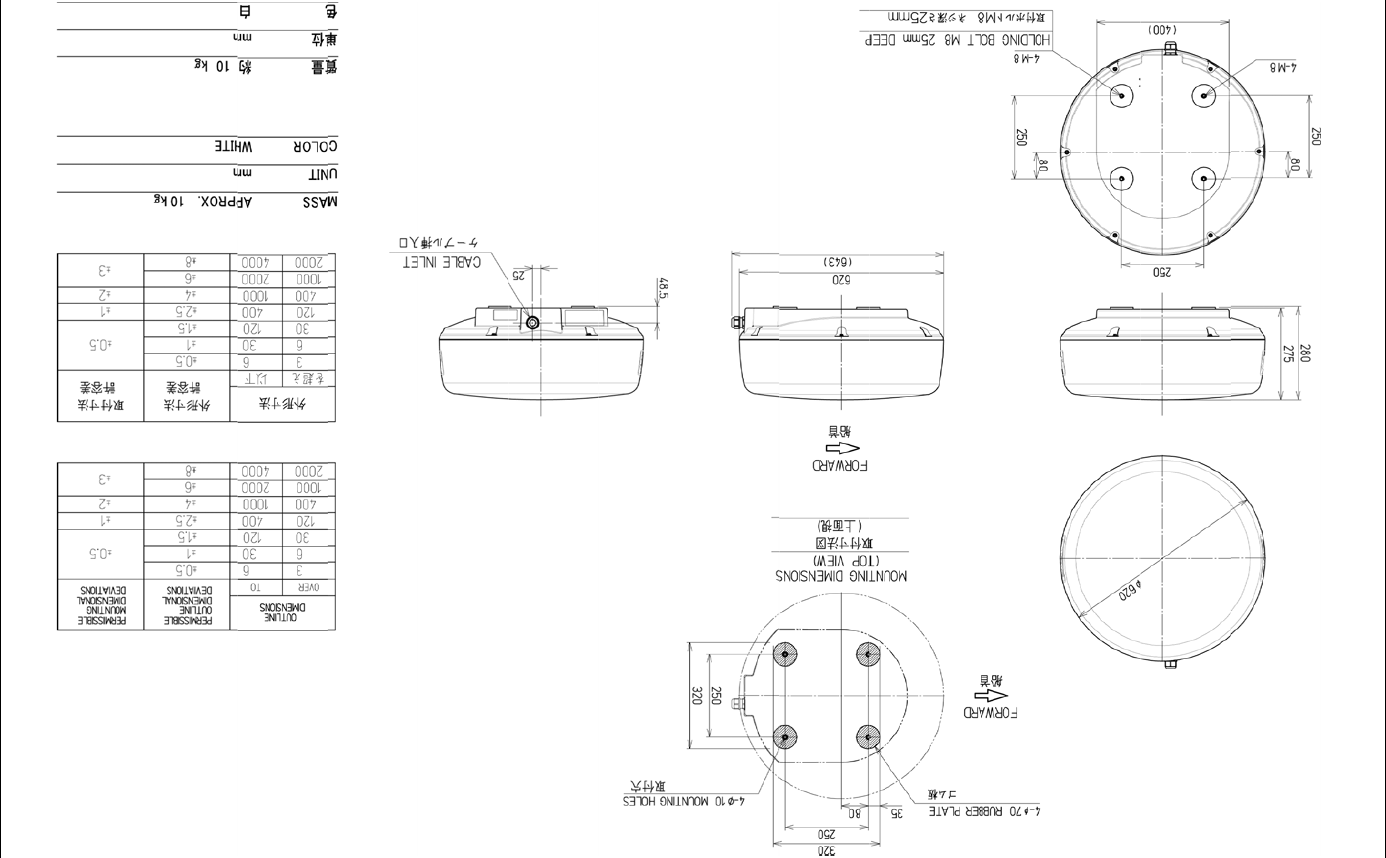
1.4 EXTERIOR DRAWINGS
Fig. 1.4-1 Exterior Drawing of Scanner Unit, Type NKE-2042
Chapter 1
GENERAL AND EQUIPMENT COMPOSITION
1.4
EXTERIOR DRAWINGS
1-8
Fig. 1.4-2 Exterior Drawing of Scanner Unit, Type NKE-2043
Chapter 1
GENERAL AND EQUIPMENT COMPOSITION
1.4
EXTERIOR DRAWINGS
1-9
INSTRUCTION MANUAL
1
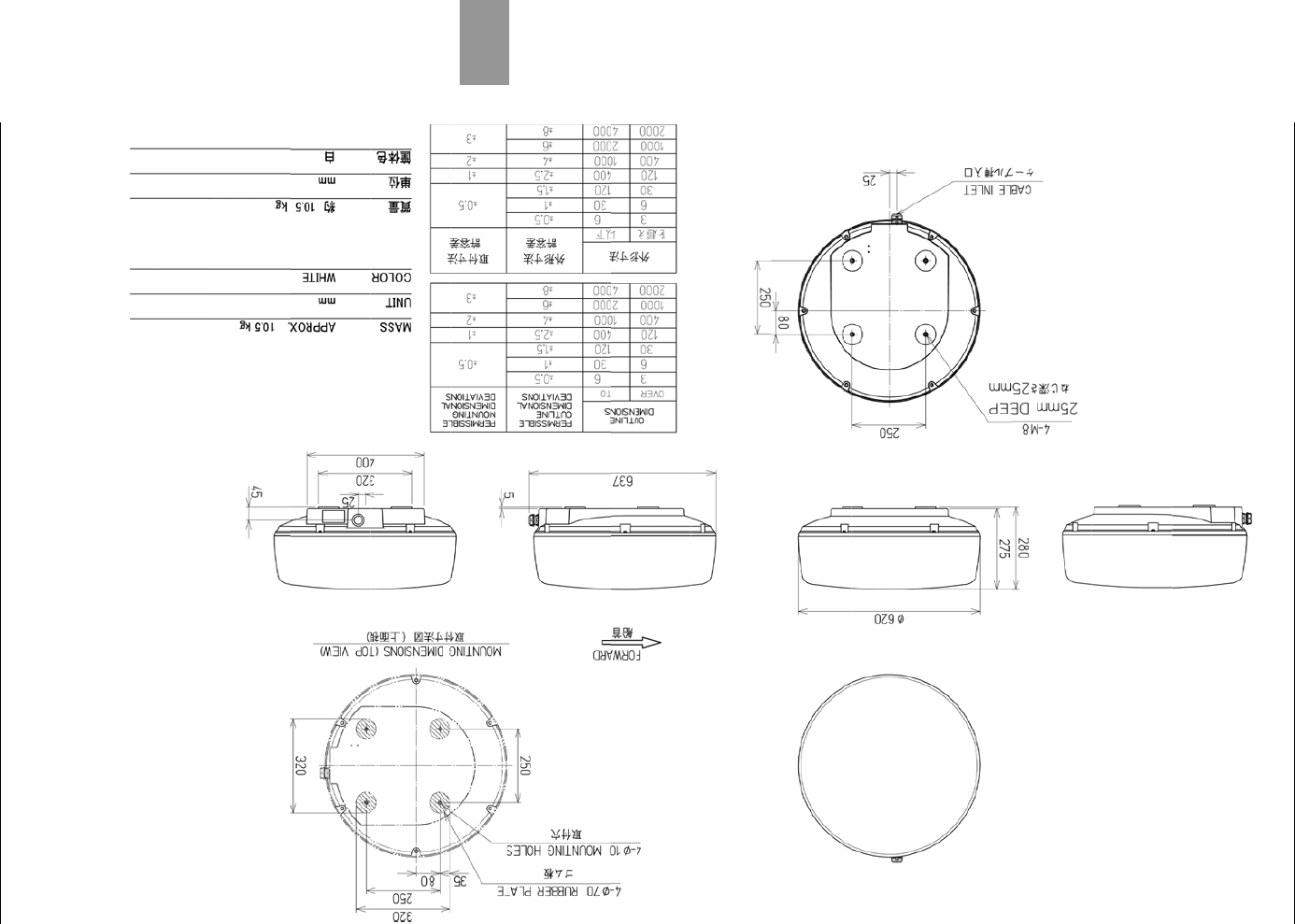
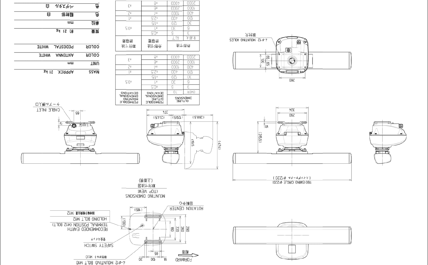
Fig. 1.4-3 Exterior Drawing of Scanner Unit, Type NKE-2062/HS
Chapter 1
GENERAL AND EQUIPMENT COMPOSITION
1.4
EXTERIOR DRAWINGS
1-10
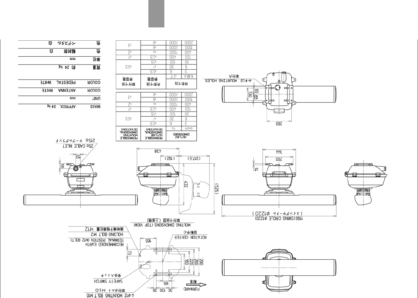
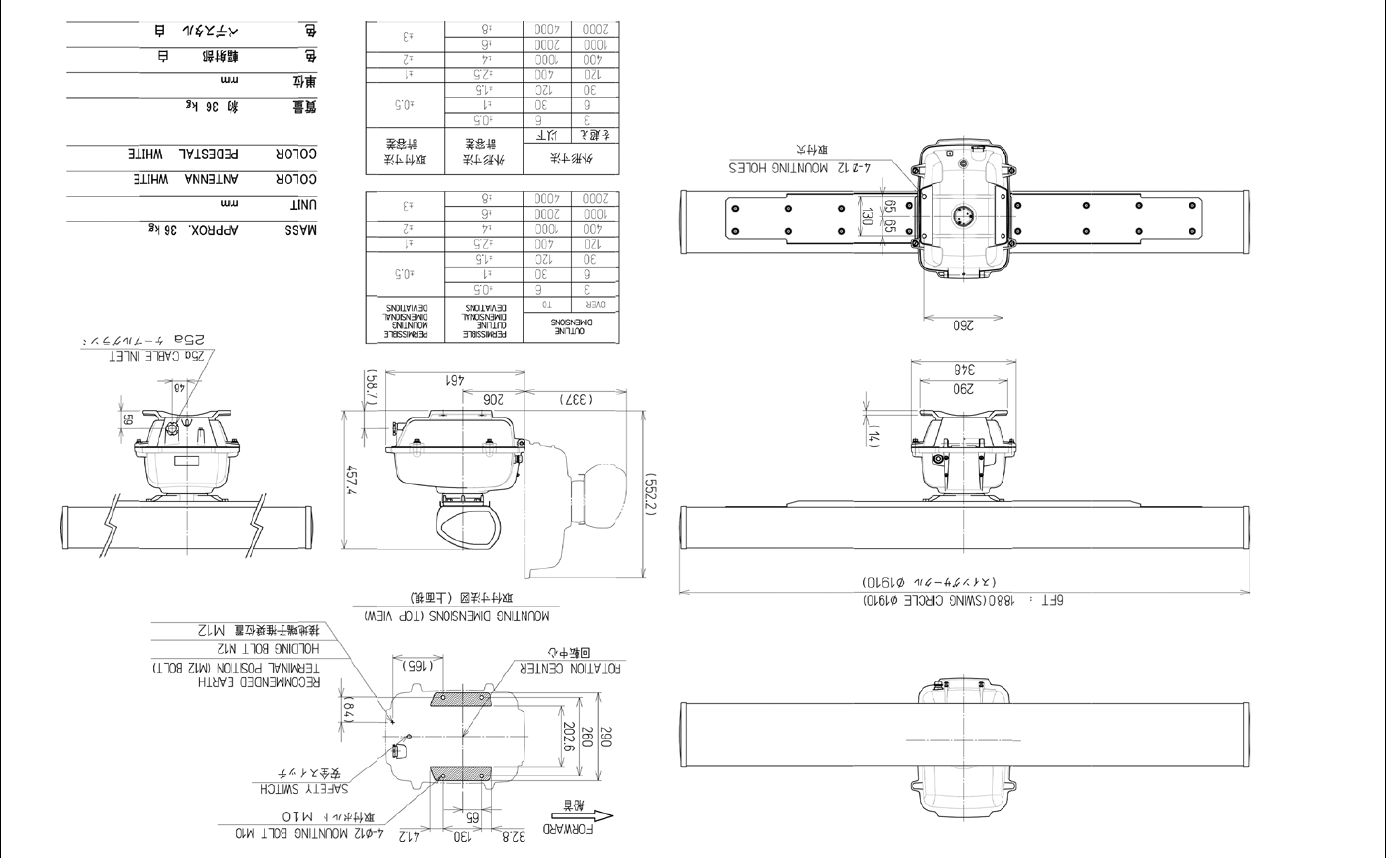
Fig. 1.4-4 Exterior Drawing of Scanner Unit, Type NKE-2063/HS
Chapter 1
GENERAL AND EQUIPMENT COMPOSITION
1.4
EXTERIOR DRAWINGS
1-11
INSTRUCTION MANUAL
1
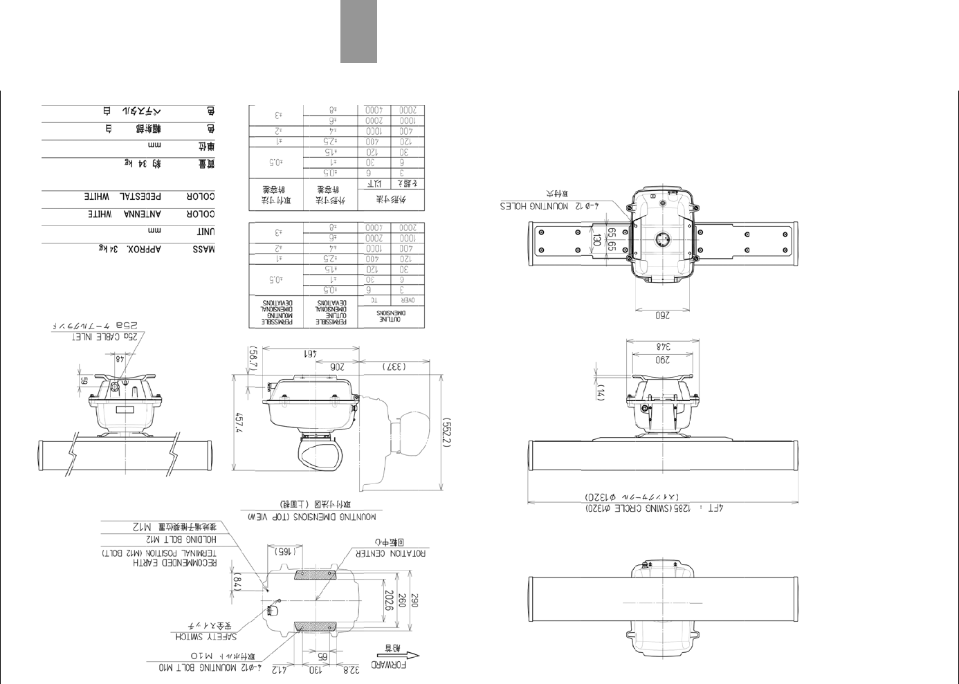
Fig. 1.4-5 Exterior Drawing of Scanner Unit, Type NKE-2103-4/4HS
Chapter 1
GENERAL AND EQUIPMENT COMPOSITION
1.4
EXTERIOR DRAWINGS
1-12
Fig. 1.4-6 Exterior Drawing of Scanner Unit, Type NKE-2103-6/6HS
Chapter 1
GENERAL AND EQUIPMENT COMPOSITION
1.4
EXTERIOR DRAWINGS
1-13
INSTRUCTION MANUAL
1
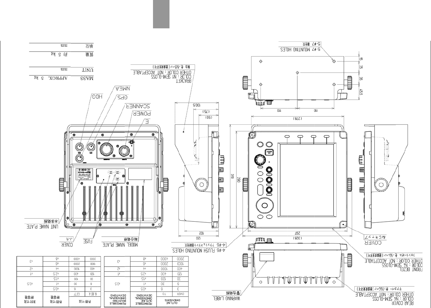
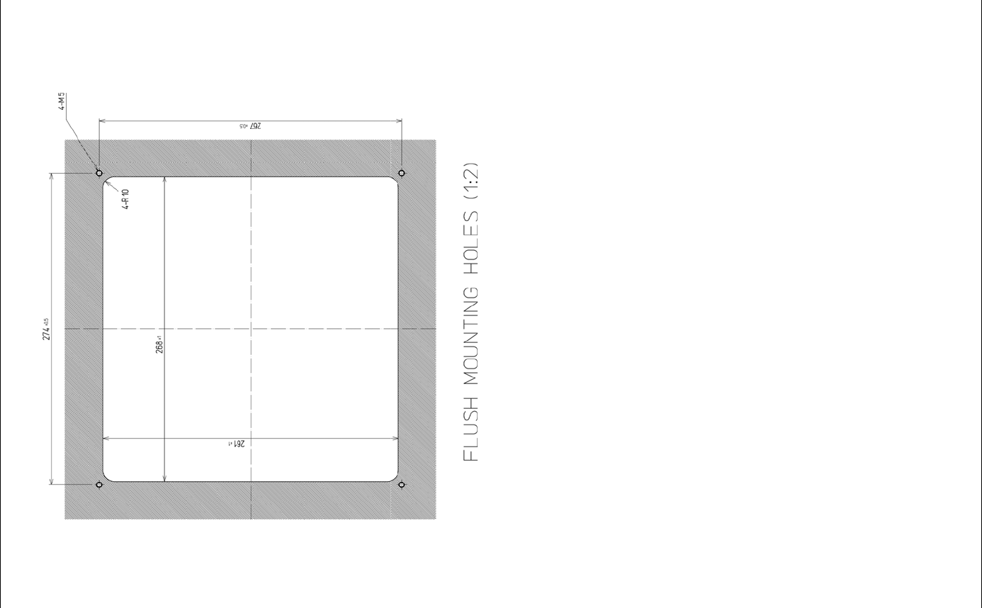
Fig. 1.4-7 Exterior Drawing of Display Unit, Type NCD-2182 (1/2)
Chapter 1
GENERAL AND EQUIPMENT COMPOSITION
1.4
EXTERIOR DRAWINGS
1-14
Fig. 1.4-7 Exterior Drawing of Display Unit, Type NCD-2182 (2/2)
Chapter 1
GENERAL AND EQUIPMENT COMPOSITION
1.5
GENERAL SYSTEM DIAGRAMS
1-15
INSTRUCTION MANUAL
1
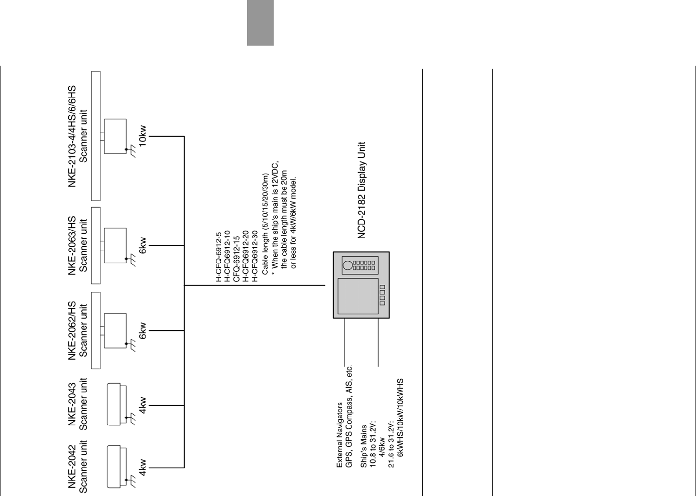
1.5 GENERAL SYSTEM DIAGRAMS
Fig. 1.5-1 General System Diagram of Radar
Reference:
Install the radar cable as far as from the cables of other radio equipment in order to prevent
other radio equipment from interfering with the radar operations.
In particular, do not install the antenna cable parallel to the cables of other radio equipment.

Chapter 1
GENERAL AND EQUIPMENT COMPOSITION
1.5
GENERAL SYSTEM DIAGRAMS
1-16