Japan Radio NKE2063 MARINE RADAR User Manual NKE2063UserMan
Japan Radio Co Ltd. MARINE RADAR NKE2063UserMan
Contents
- 1. Users Manual 1
- 2. Users Manual 2
- 3. Users Manual 3
- 4. Users Manual 4
Users Manual 3
Chapter 2
OPERATIONS
2.8
BASIC MENU OPERATIONS
2-77
2
INSTRUCTION MANUAL
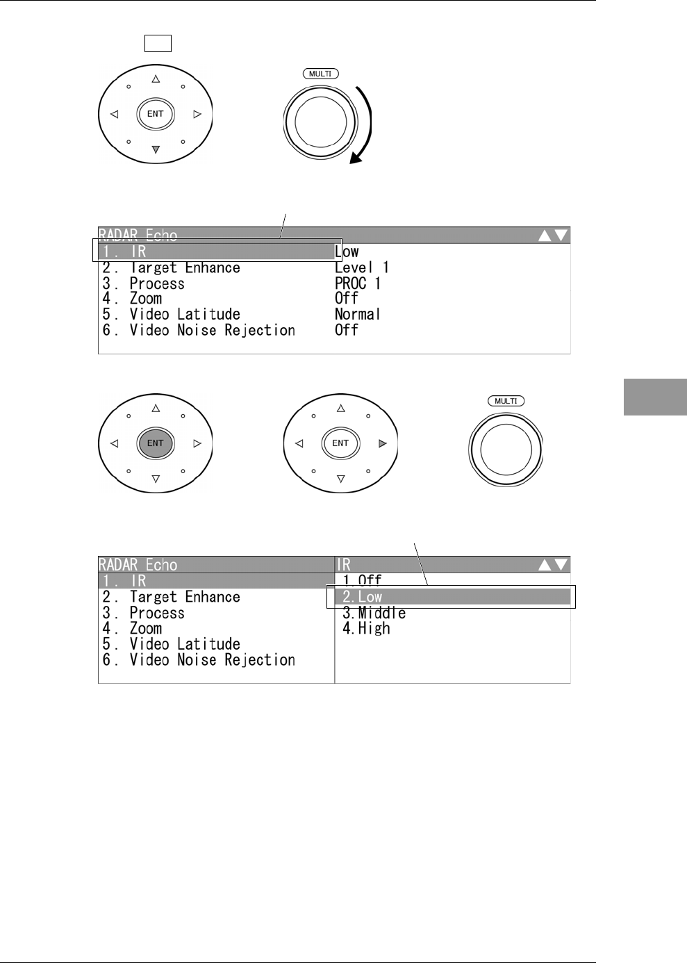
4Press the cursor key (down) or turn the [MULTI] control (clockwise) to
select IR .
5Press the [ENT] key, the cursor key (right) or the [MULTI] control.
"IR" menu appears.
Selectable items are displayed on the right pane of the menu.
"IR" is colo
r
-inverted.
The current setting is colo
r
-inverted.
Chapter 2
OPERATIONS
2.8
BASIC MENU OPERATIONS
2-78
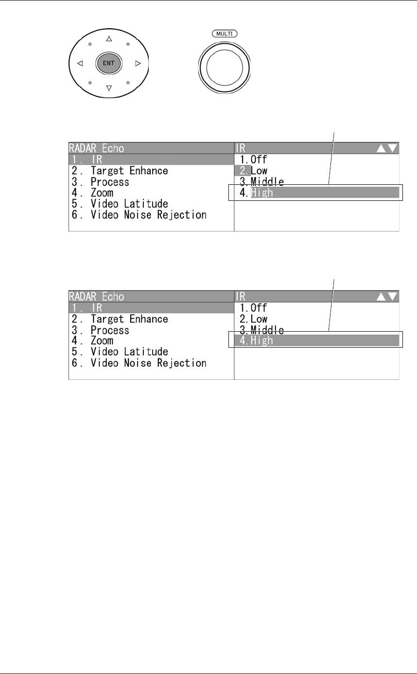
6Select the desired item, then press the [ENT] key or the [MULTI] control.
7The setting is determined and displayed.
z Closing the menu
Repeatedly press the [CLEAR] key or the cursor key (left) to return to the upper level
and then close the menu screen.
Select the desired item.
Setting is determined.
Chapter 2
OPERATIONS
2.9
RADAR ECHO SETTINGS
2-79
2
INSTRUCTION MANUAL
2.9 RADAR ECHO SETTINGS
This function enables the setting of detail information about radar echo.
"RADAR Echo" operations
1Open RADAR Echo from the Main Menu.
"RADAR Echo" menu appears.
Detail information about radar signal processing can be set by changing the settings
of the menu items.
Reference:
After the settings for radar signal processing are changed, small targets may not be
displayed or unwanted waves may not be suppressed. Thus, do not make a significant
change in the settings.
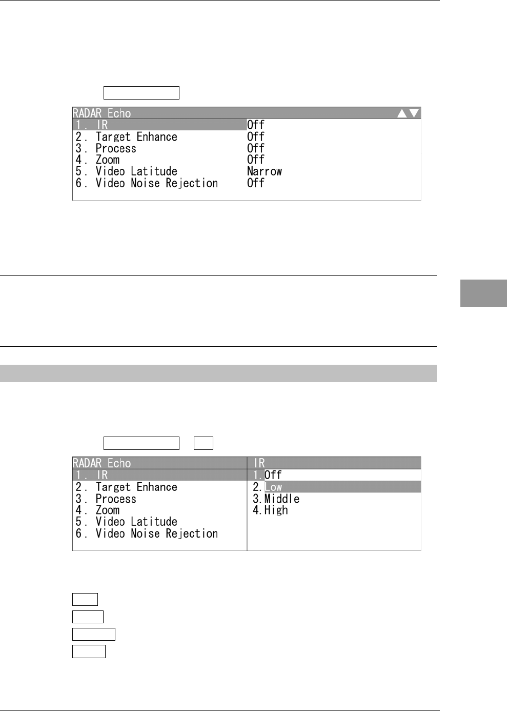
2.9.1 SETTING RADAR INTERFERENCE REJECTION
Setting Radar Interference Rejection
Use this function to eliminate interference waves from other radars.
1Open RADAR Echo - IR .
"IR" menu appears.
Off : Interference rejecter off
Low : Interference rejection level - low
Middle : Interference rejection level - moderate
High : Interference rejection level - high
Chapter 2
OPERATIONS
2.9
RADAR ECHO SETTINGS
2-80
When a high interference rejection level is selected, the radar's ability of detecting small
targets such as buoys and small boats lowers.
In general, Low should be selected.
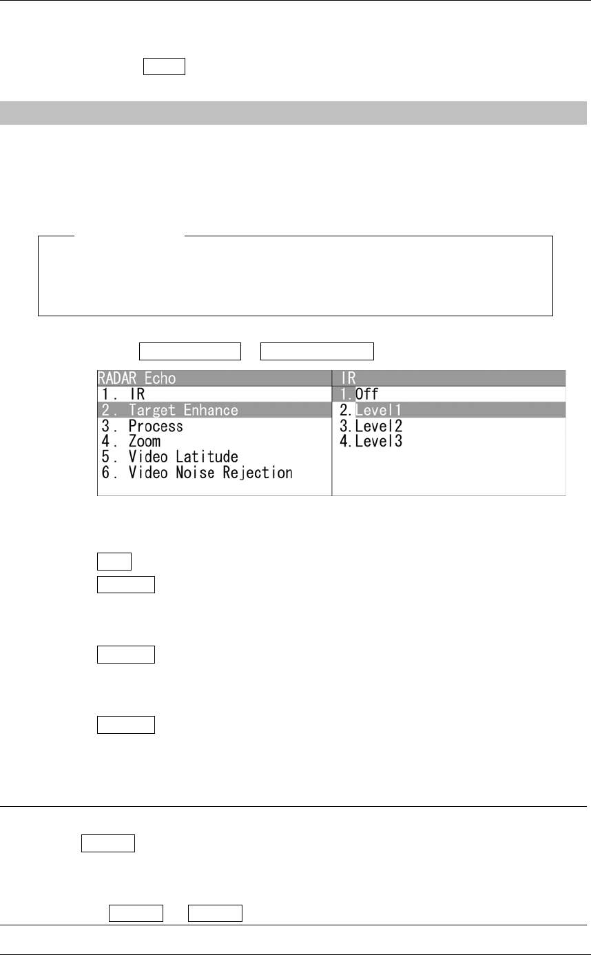
2.9.2 SETTING FOR ENHANCING TARGETS
Setting for Enhancing Targets
The dimension of video display is enlarged in angle and distance.
Note:
z When target enhancement function is used, echo displays of two targets closing
in angle and distance may be displayed in PPI screen as one target.
1Open RADAR Echo - Target Enhance .
"Target Enhance" menu appears.
Off : Select this mode particularly when resolution is required.
Level1 : Select this mode in general.
Expands the radar echo area at 1 step for vertical direction and at 1
step for horizontal direction.
Level2 : Select this mode to easily view the radar video.
Expands the radar echo area at 1 step for vertical direction and at 2
steps for horizontal direction.
Level3 : Select this mode to detect small targets such as buoys.
Expands the radar echo area at 2 steps for vertical direction and at
3 steps for horizontal direction.
Reference:
When Level3 is selected, sea clutter returns and rain/snow clutter returns are apt to be
enhanced. When using this enhance mode, operate the [SEA] control and the [RAIN]
control to suppress sea clutter returns and rain/snow clutter returns.
In general, Level1 or Level2 should be selected.
Chapter 2
OPERATIONS
2.9
RADAR ECHO SETTINGS
2-81
2
INSTRUCTION MANUAL
2.9.3 PROCESS
Process
This function reduces unnecessary noise to highlight targets.
Note:
z When viewing a radar beacon, SART signal, or fast moving target on the radar
display, do not use this function.
z This function is suitable for use in TM mode.
z When used in RM mode, use with N Up or C Up. This can be used with H Up,
however, the video may be blurred. Use this in TM mode.
Reference:
The bearing data input is required for video processing.
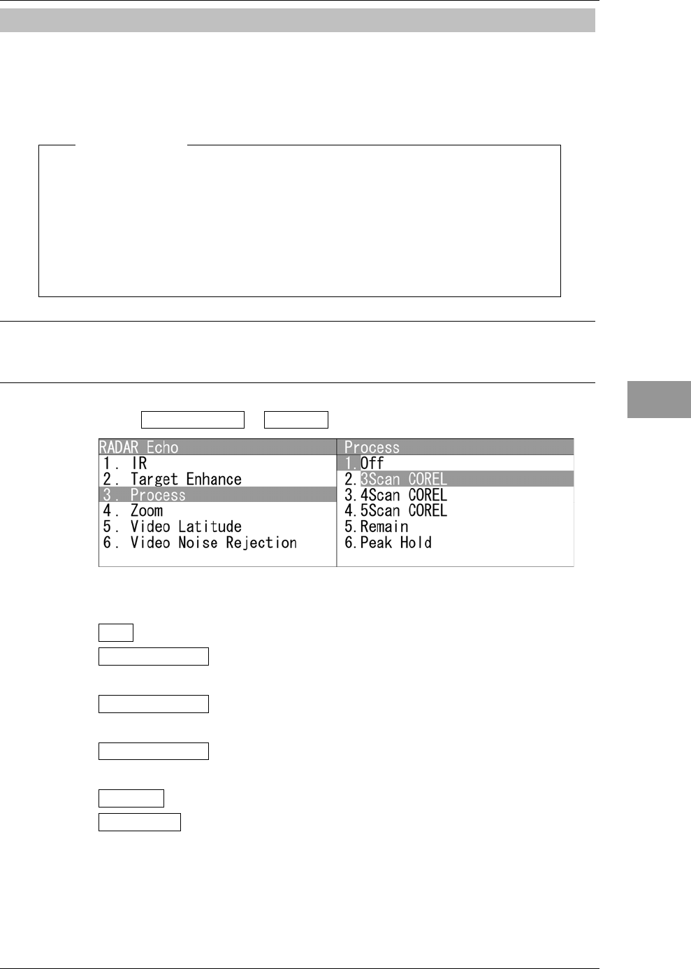
1Open RADAR Echo - Process .
"Process" menu appears.
Off : Select this mode in general.
3Scan COREL : Select this mode when many rain/snow clutter returns are
detected.
4Scan COREL : Select this mode to highlight targets while suppressing sea
clutter returns.
5Scan COREL : Select this mode to detect small targets hidden by sea clutter
returns.
Remain : Select this mode when own ship yaws wildly.
Peak Hold : Select this mode to detect small targets of which detection
probability is low.
Chapter 2
OPERATIONS
2.9
RADAR ECHO SETTINGS
2-82
Note:
z When "COREL" is set, the image becomes smaller.
z When "Remain" or "Peak Hold" is set, the afterimage will appears.
2.9.4 ZOOMING
Zooming
This function doubles the size of radar video.
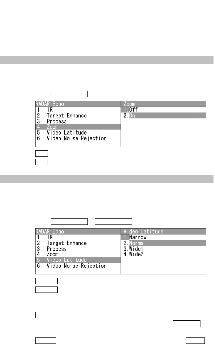
1Open RADAR Echo - Zoom .
Off : Not zoomed.
On : Zoomed.
2.9.5 VIDEO LATITUDE
Video Latitude
Select the dynamic range in which receiving signals are to be shown on the radar
display.
1Open RADAR Echo - Video Latitude .
Narrow : Narrows the dynamic range at short range.
Normal : Standard setting
The dynamic range varies depending on the actual range:
Short range > long range
Wide1 : Use this mode when rainy weather intensifies unwanted waves.
The dynamic range is about twice as wide as when NORMAL is
selected.
Wide2 : Use this mode when rain clouds remain even when using Wide1 .
Chapter 2
OPERATIONS
2.9
RADAR ECHO SETTINGS
2-83
2
INSTRUCTION MANUAL
z Video Latitude
Select Normal in standard, and Wide1 in rainy weather.
Narrow clearly displays short-range videos when STC is used in manual mode.
2.9.6 VIDEO NOISE REJECTION
Video Noise Rejection
This function rejects signals that assumed as noise and clutter in radar videos.
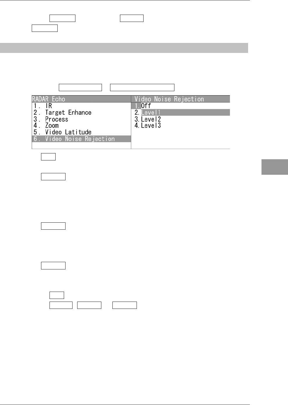
1Open RADAR Echo - Video Noise Rejection .
Off : Turns off the noise rejection function, and displays all signals.
Targets are popped up from noise and displayed like analog signals.
Level1 : Rejects the signals of definitely unwanted waves (noise and clutter).
When detection of targets or unwanted waves is not definite, the
signals are displayed.
When detection of targets is definite, the signals are displayed.
Level2 : Rejects the signals of definitely unwanted waves (noise and clutter).
When detection of targets or unwanted waves is not definite, the
signals are rejected.
When detection of targets is definite, the signals are displayed.
Level3 : Select if "Level1" and "Level2" cannot reject the signals enough.
z Video Noise Rejection
Select Off to display radar videos like analog signals.
Select Level1 , Level2 or Level3 to suppress noise and clutter.
Chapter 2
OPERATIONS
2.10
RADAR TRAIL LENGTH SETTING
2-84
2.10 RADAR TRAIL LENGTH SETTING
"Sets the maximum time for displaying radar trails.
Reference:
For details of radar trail settings, see Section "2.7.5 DISPLAYING OTHER SHIP'S
TRACKS (RADAR TRAILS)".
"Trails" operations
1Open Trails from the Main Menu.
"Trails" menu appears.
Maximum value of radar trail display time (MAX Interval)
Select the maximum time for displaying radar trails.
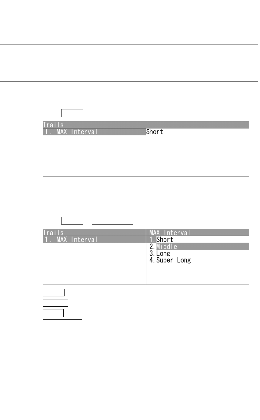
1Open Trails - MAX Interval .
Short : Sets 15 minutes as the maximum time for radar trails display.
Middle : Sets 15 minutes as the maximum time for radar trails display.
Long : Sets 1 hour as the maximum time for radar trails display.
Super Long : Sets 24 hours as the maximum time for radar trails display.

Chapter 2
OPERATIONS
2.10
RADAR TRAIL LENGTH SETTING
2-85
2
INSTRUCTION MANUAL
z Maximum value of radar trail display time
Select Short when short radar trails are often used in bays and the likes.
Select Super Long when long radar trails are necessary for ocean navigation.
Middle is for specification between Short and Long .
Continuous trails are available with all the options.
Short:
Off/15sec/30sec/1min/2min/3min/4min/5min/6min/10min/15min/All
Middle:
Off/30sec/1min/2min/3min/4min/5min/6min/10min/15min/30min/All
Long:
Off/1min/2min/3min/4min/5min/6min/10min/15min/30min/1hr/All
Super Long:
Off/30min/1hr/2hr/3hr/4hr/5hr/6hr/10hr/12hr/24hr/All
Chapter 2
OPERATIONS
2.11
MARKER SETTING
2-86
2.11 MARKER SETTING
Sets operations for EBLs, parallel cursors, cursors and range rings.
"Marker" operations
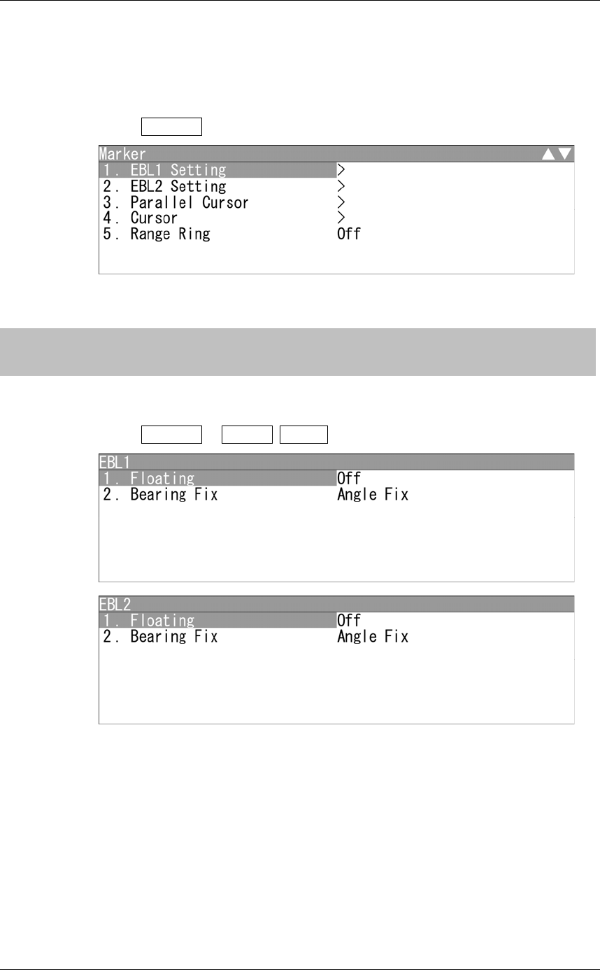
1Open Marker from the Main Menu.
"Marker" menu appears.
2.11.1 SETTING OPERATIONS FOR EBLS (ELECTRONIC
BEARING LINES)
"EBL" operations
1Open Marker - EBL1 EBL2 .
"EBL" menu appears.
Chapter 2
OPERATIONS
2.11
MARKER SETTING
2-87
2
INSTRUCTION MANUAL
Setting the mode to move the starting point of EBL (Floating setting)
Reference:
Course and latitude/longitude data input is required for floating setting.
The heading and latitude/longitude input are not required during floating (Screen FIX).
When this function is set to L/L Fix and the starting point of an EBL is moved to a
position, the starting point can be fixed at the latitude and longitude of that position.
When the function is set to Screen Fix , the starting point of an EBL is fixed on the
radar display. The starting point is always indicated at the same position on the radar
display even when the own ship has moved.
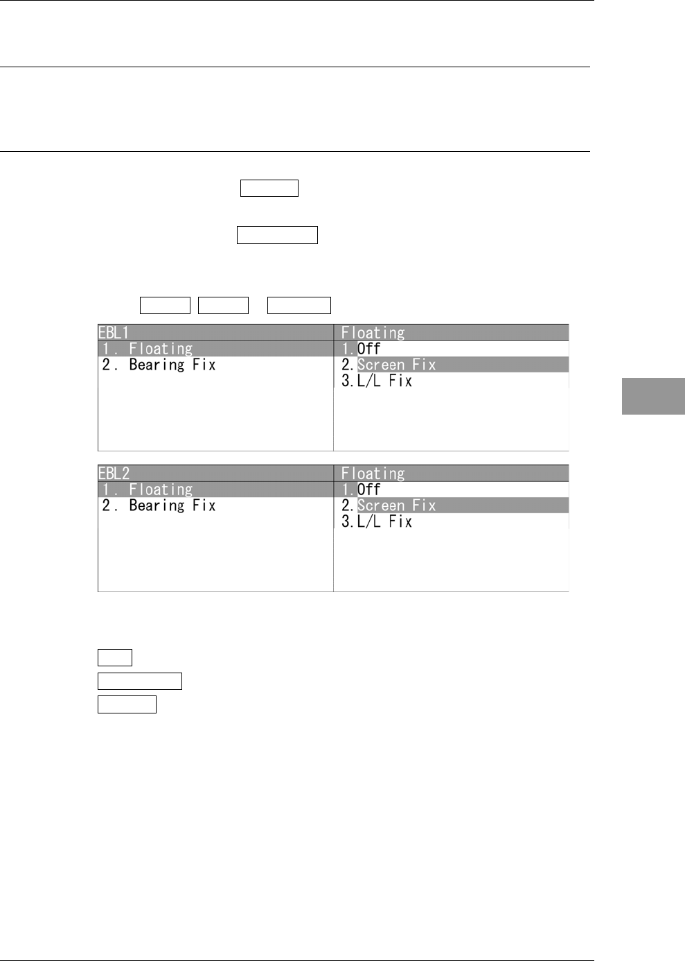
1Open EBL1 EBL2 - Floating .
"Floating" menu appears.
Off : Floating mode is disabled.
Screen Fix : The starting point of EBL is fixed on the radar display.
L/L Fix : The starting point of EBL is fixed at specific latitude and
longitude.
Chapter 2
OPERATIONS
2.11
MARKER SETTING
2-88
Setting the EBL bearing fix mode
Reference:
Course data input is required for Bearing Fix setting.
While this function is set to Angle Fix , an EBL is fixed to the preset bearing. For
example, if the true bearing 020° is preset, the EBL is fixed to the true bearing 020° even
when the own ship turns.
While the function is set to Screen Fix , the EBL is fixed on the radar display.
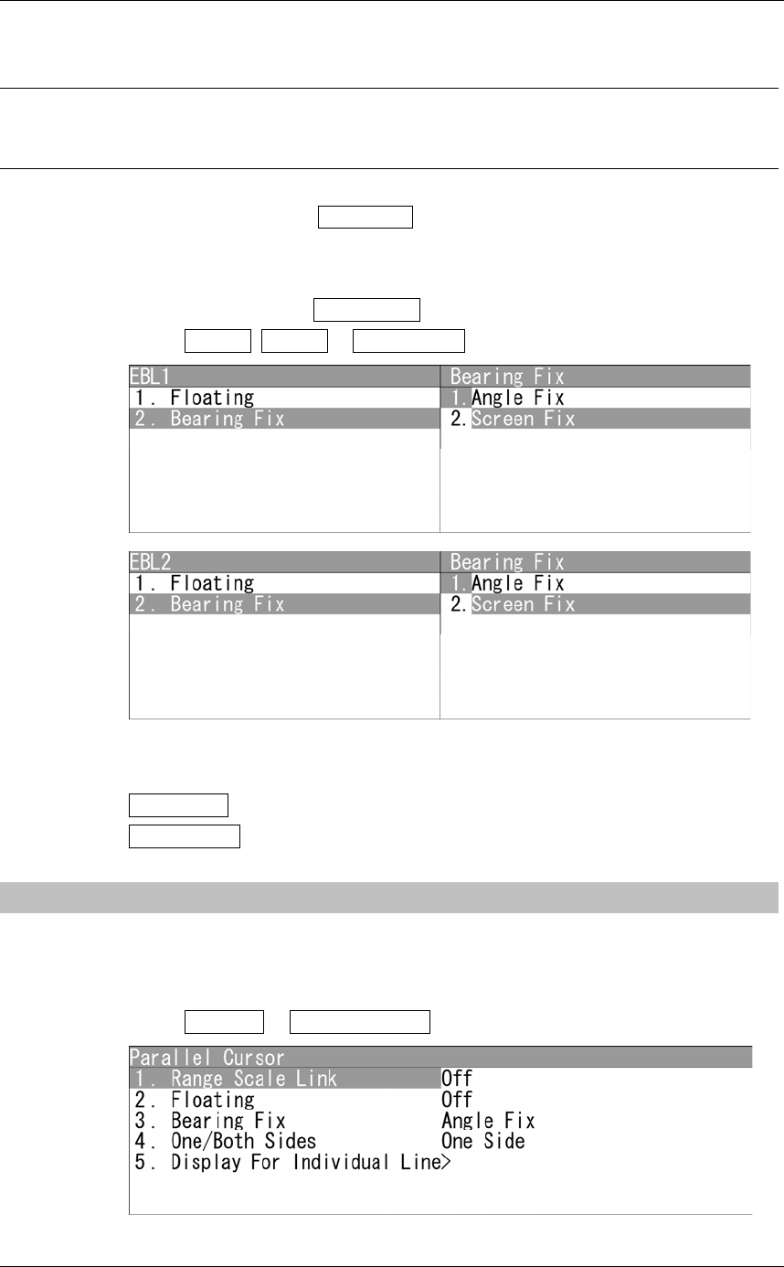
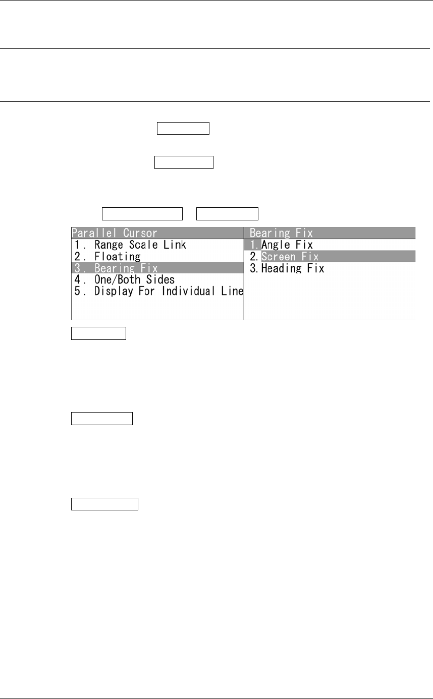
1Open EBL1 EBL2 - Bearing Fix .
"Bearing Fix" menu appears.
Angle Fix : EBL bearing is fixed to the preset value.
Screen Fix : EBL bearing is fixed on the radar display.
2.11.2 SETTING OPERATIONS FOR PARALLEL CURSORS
Parallel cursors can be set.
"Parallel Cursor" operations
1Open Marker - Parallel Cursor .
"Parallel Cursor" menu appears.
Chapter 2
OPERATIONS
2.11
MARKER SETTING
2-89
2
INSTRUCTION MANUAL
Range Scale Link
When a range is switched, parallel cursors link to a radar range scale for display.
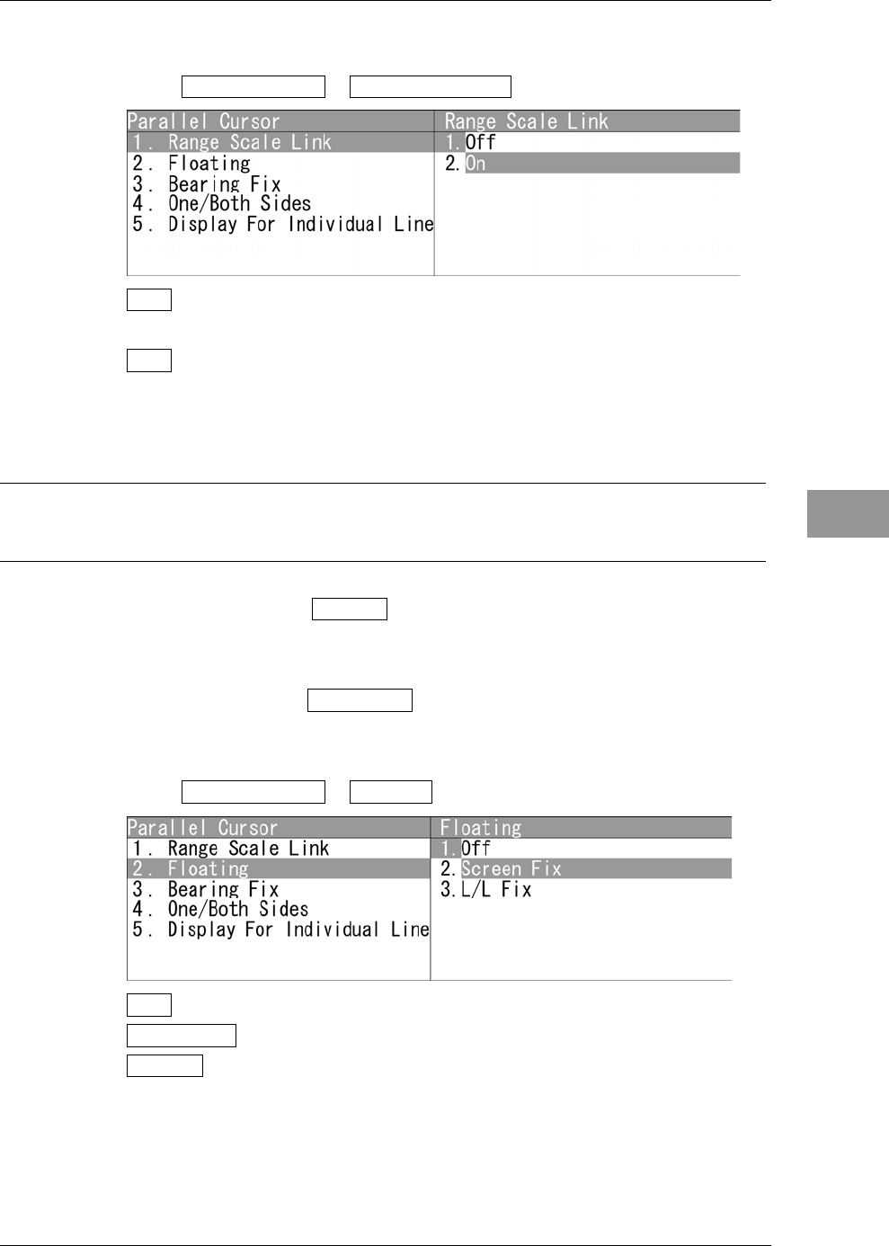
1Open Parallel Cursor - Range Scale Link .
Off : If the range is switched, the width between parallel index lines changes in
accordance with the radar range scale.
On : If the range is switched, the width between parallel index lines remains
fixed.
Setting the mode to move the starting point of parallel cursor (Floating setting)
Reference:
Course and latitude/longitude data input is required for floating setting.
When this function is set to L/L Fix and the starting point of a parallel cursor is
moved to a position, the starting point can be fixed at the latitude and longitude of that
position.
When the function is set to Screen Fix , the starting point of a parallel cursor is fixed
on the radar display. The starting point is always indicated at the same position on the
radar display even when the own ship has moved.
1Open Parallel Cursor - Floating .
Off : Floating mode is disabled.
Screen Fix : Fixes the start point of parallel cursor to the radar display.
L/L Fix : The starting point of parallel cursor is fixed at specific latitude and
longitude.
Chapter 2
OPERATIONS
2.11
MARKER SETTING
2-90
Setting bearing fix mode of parallel cursor
Reference:
y Course data input is required for bearing fix mode setting.
y True bearing signal input is required for N Up.
If this function is set to Angle Fix , the parallel cursor also rotates in accordance with
the bearing while the own ship is turning.
If the function is set to Screen Fix , the parallel index lines are fixed within the radar
display even while the own ship is turning. The parallel index lines are displayed at the
same place even while the own ship is turning.
1Open Parallel Cursor - Bearing Fix .
Angle Fix : The angle of the parallel cursors is set in true bearing.
For N Up and C Up, the cursors are displayed in true bearing
irrespective of changes in the course of own ship.
For H Up, the angle of the parallel cursors changes as the course
of own ship changes.
Screen Fix : Fixes the parallel cursor display to the radar display.
For H Up, N Up, and C Up, the angle of the parallel cursors stays
the same on the screen.
When own ship is engaged in TM motions, the parallel cursors
move as own ship moves.
Heading Fix : The parallel cursors are displayed while the relative angle of the
ship's heading bearing line stays the same.
For H Up, the ship's heading bearing line does not change even
though the course of own ship changes; therefore, the parallel
cursors do not move.
For N Up, the ship's heading bearing line changes as the course of
own ship changes; therefore, the parallel cursors also change as
the course of own ship changes.
Chapter 2
OPERATIONS
2.11
MARKER SETTING
2-91
2
INSTRUCTION MANUAL
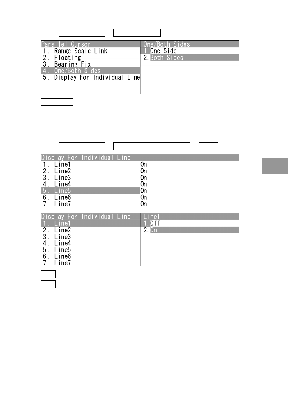
Setting "One/Both Sides"
Selects "One Side" or "Both Sides" for parallel cursor display.
1Open Parallel Cursor - One/Both Sides .
One Side : The parallel cursors are displayed in "One Side" mode.
Both Sides : The parallel cursors are displayed in "Both Sides" mode.
Displaying individual parallel cursors
Individual parallel cursors can be displayed/hidden.
1Open Parallel Cursor - Display For Individual Line - Line1 .
Off : The parallel cursor is not displayed.
On : The parallel cursor is displayed.
The line nearest to the own ship is specified as Line1.
Chapter 2
OPERATIONS
2.11
MARKER SETTING
2-92
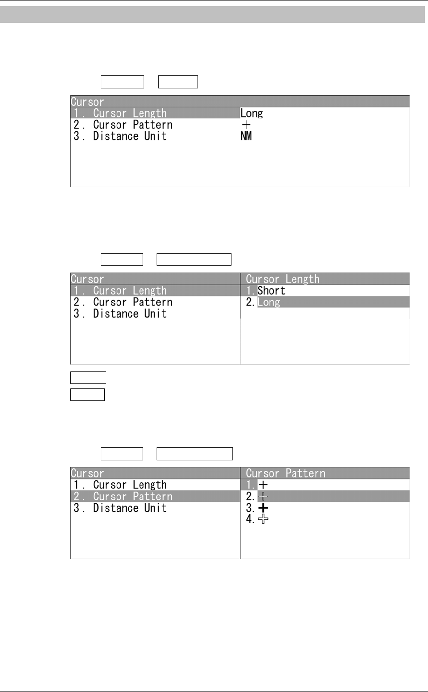
2.11.3 SETTING CURSORS
This function enables the setting of detail information about cursor display.
"Cursor" operations
1Open Marker - Cursor .
"Cursor" menu appears.
Cursor Length
Sets the length of the cross cursor mark on the radar display.
1Open Cursor - Cursor Length .
Short : Cuts the cross cursor mark in length.
Long : Makes the cross cursor mark twice as long as when "Short" is selected.
Cursor Pattern
Selects the type of the cross cursor mark on the radar display.
1Open Cursor - Cursor Pattern .
Chapter 2
OPERATIONS
2.11
MARKER SETTING
2-93
2
INSTRUCTION MANUAL
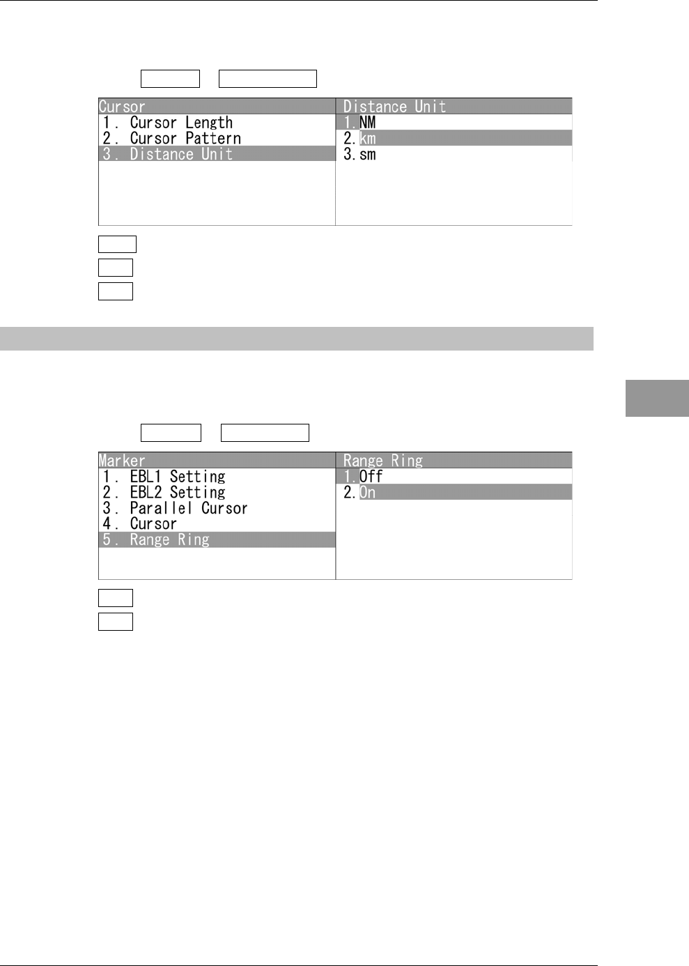
Distance Unit
Sets the distance unit for cursor.
1Open Cursor - Distance Unit .
NM : The distance unit is set to NM.
km : The distance unit is set to km.
sm : The distance unit is set to sm.
2.11.4 SETTING RANGE RINGS
Displays/hides the range rings.
Setting the range rings
1Open Marker - Range Ring .
Off : The range rings are not displayed.
On : The range rings are displayed.
Chapter 2
OPERATIONS
2.12
DISPLAY COLOR SETTING
2-94
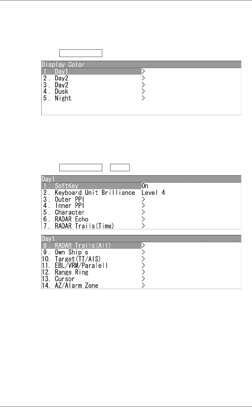
2.12 DISPLAY COLOR SETTING
This function enables the setting of detail information about radar display.
"Display Screen" operations
1Open Display Color from the Main Menu.
"Display Color" menu appears.
Setting each items
Sets the display color of each item.
z Day1
1Open Display Color - Day1 .
"Day1" menu appears.
Chapter 2
OPERATIONS
2.12
DISPLAY COLOR SETTING
2-95
2
INSTRUCTION MANUAL
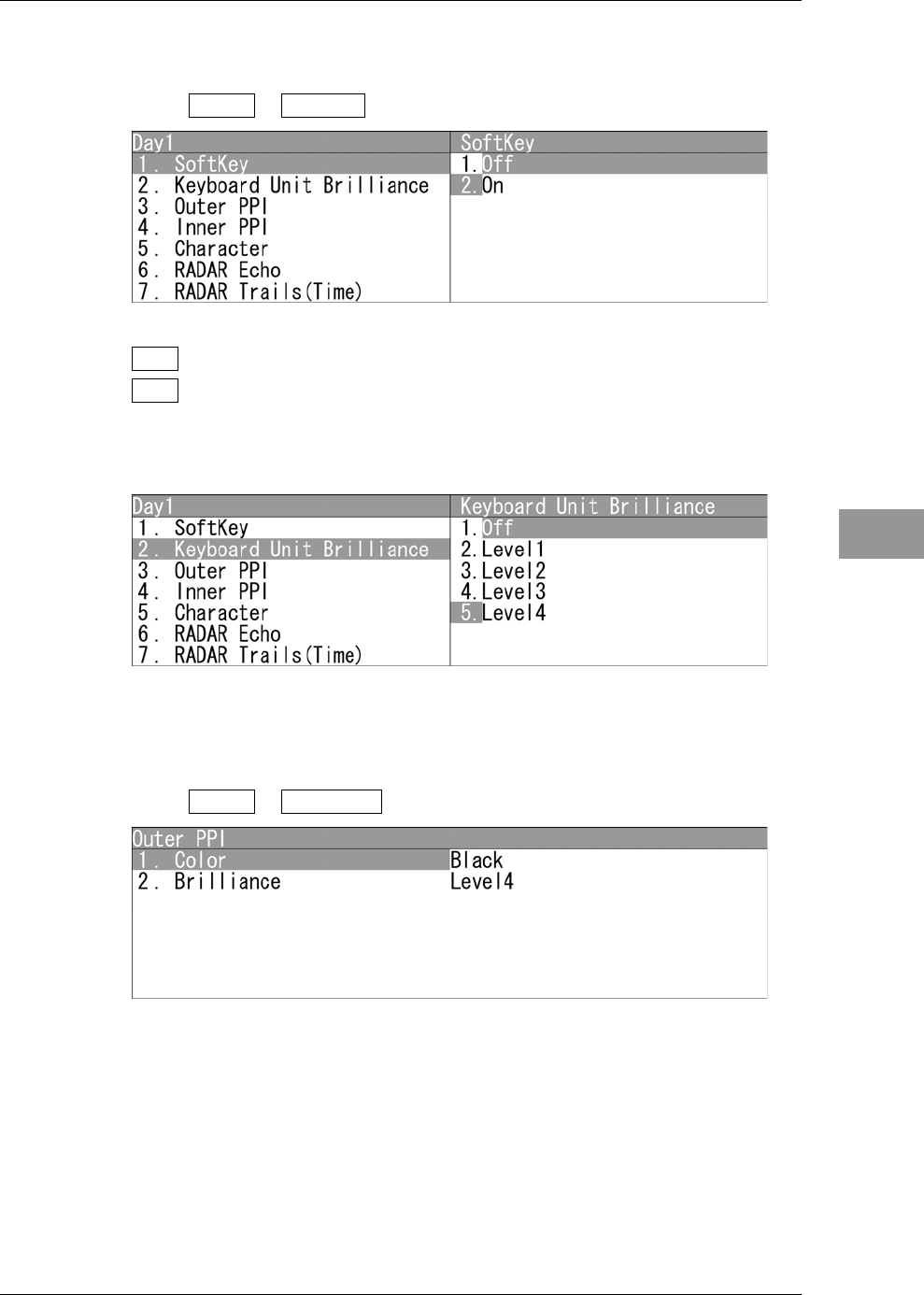
SoftKey
If "Off" is selected, "Day1" is not displayed for the "Display Screen" soft keys.
1Open Day1 - SoftKey .
"SoftKey" menu appears.
Off : "Day1" is not displayed for the "Display Screen" soft keys.
On : "Day1" is displayed for the "Display Screen" soft keys.
Keyboard Unit Brilliance
Adjusts the brilliance of operation panel.
"Keyboard Unit Brilliance" menu appears.
Outer PPI
Adjusts the background color outside the bearing scale.
1Open Day1 - Outer PPI .
"Outer PPI" menu appears.
Chapter 2
OPERATIONS
2.12
DISPLAY COLOR SETTING
2-96
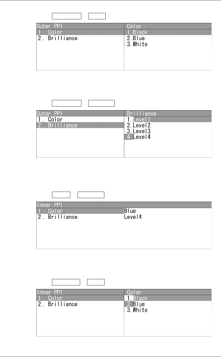
z Display Color
1Open Outer PPI - Color .
"Color" menu appears.
z Display Brilliance
1Open Outer PPI - Brilliance .
"Brilliance" menu appears.
Inner PPI
Adjusts the background color inside the bearing scale.
1Open Day1 - Inner PPI .
"Inner PPI" menu appears.
z Display Color
1Open Inner PPI - Color .
"Color" menu appears.
Chapter 2
OPERATIONS
2.12
DISPLAY COLOR SETTING
2-97
2
INSTRUCTION MANUAL
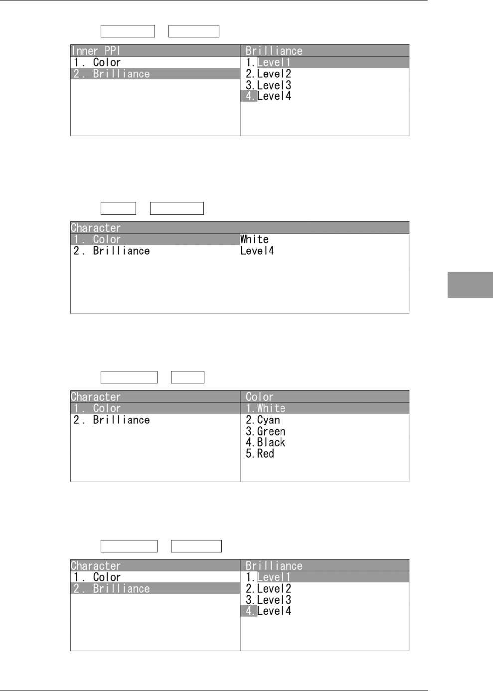
z Display Brilliance
1Open Inner PPI - Brilliance .
"Brilliance" menu appears.
Characters
Adjusts the colors of characters and bearing scales.
1Open Day1 - Character .
"Character" menu appears.
z Display Color
1Open Character - Color .
"Color" menu appears.
z Display Brilliance
1Open Character - Brilliance .
"Brilliance" menu appears.
Chapter 2
OPERATIONS
2.12
DISPLAY COLOR SETTING
2-98
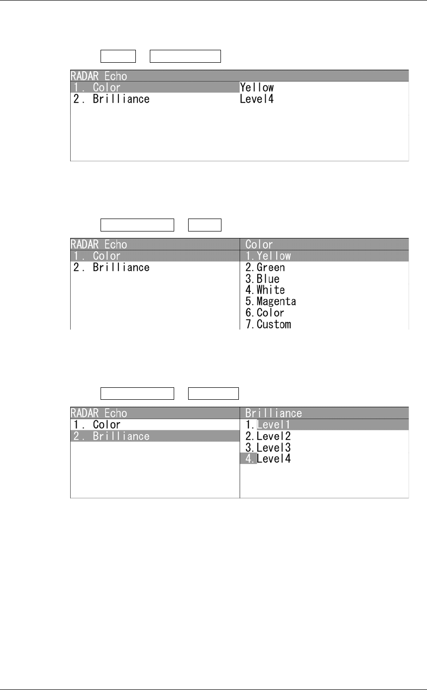
RADAR Echo
Adjusts the colors of radar echoes.
1Open Day1 - RADAR Echo .
"RADAR Echo" menu appears.
z Display Color
1Open RADAR Echo - Color .
"Color" menu appears.
z Display Brilliance
1Open RADAR Echo - Brilliance .
"Brilliance" menu appears.
Chapter 2
OPERATIONS
2.12
DISPLAY COLOR SETTING
2-99
2
INSTRUCTION MANUAL
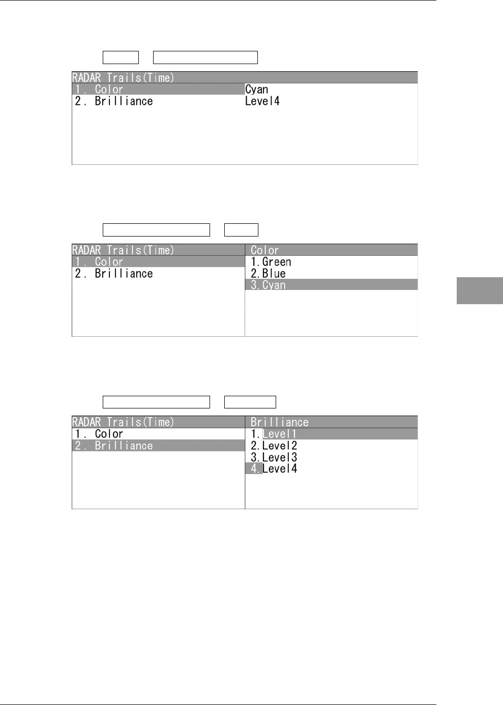
RADAR Trails(Time)
Adjusts the colors of radar trails (time).
1Open Day1 - RADAR Trails(Time) .
"RADAR Trails(Time)" menu appears.
z Display Color
1Open RADAR Trails(Time) - Color .
"Color" menu appears.
z Display Brilliance
1Open RADAR Trails(Time) - Brilliance .
"Brilliance" menu appears.
Chapter 2
OPERATIONS
2.12
DISPLAY COLOR SETTING
2-100
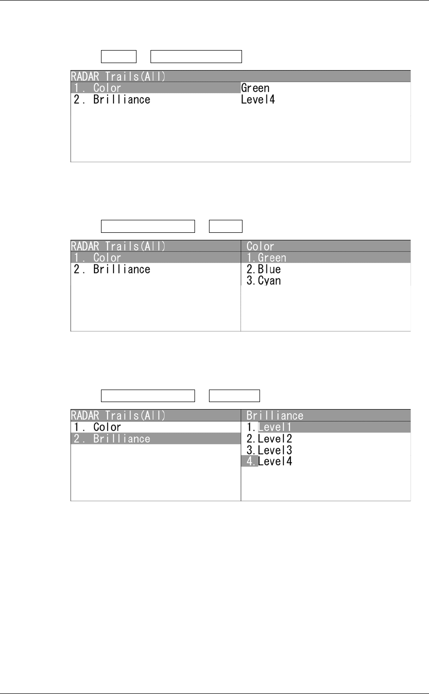
RADAR Trails(All)
Adjusts the colors of radar trails (continuous).
1Open Day1 - RADAR Trails(All) .
"RADAR Trails(All)" menu appears.
z Display Color
1Open RADAR Trails(All) - Color .
"Color" menu appears.
z Display Brilliance
1Open RADAR Trails(All) - Brilliance .
"Brilliance" menu appears.
Chapter 2
OPERATIONS
2.12
DISPLAY COLOR SETTING
2-101
2
INSTRUCTION MANUAL
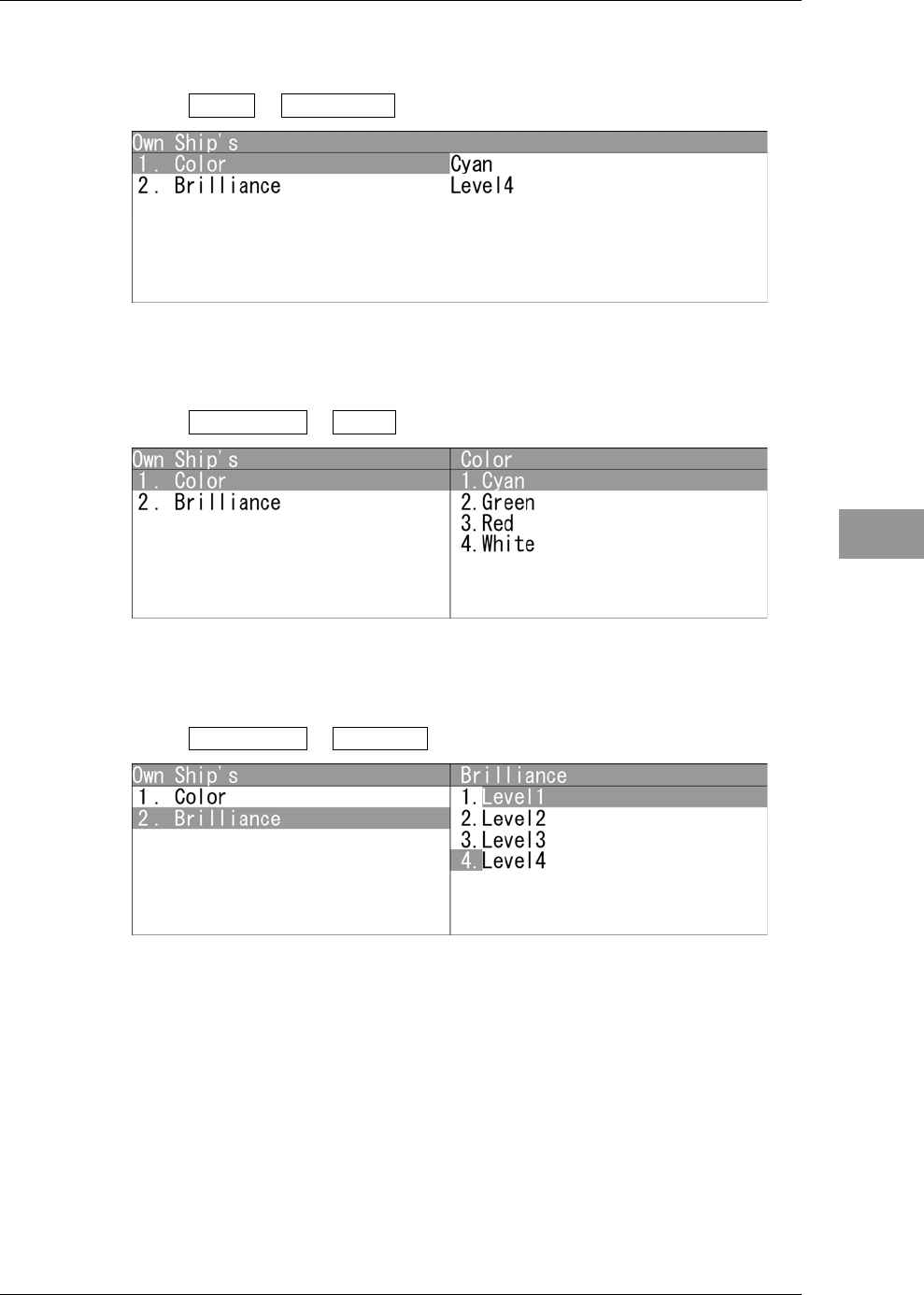
Own Ship's
Adjusts the colors of own ship/barge.
1Open Day1 - Own Ship's .
"Own Ship's" menu appears.
z Display Color
1Open Own Ship's - Color .
"Color" menu appears.
z Display Brilliance
1Open Own Ship's - Brilliance .
"Brilliance" menu appears.
Chapter 2
OPERATIONS
2.12
DISPLAY COLOR SETTING
2-102
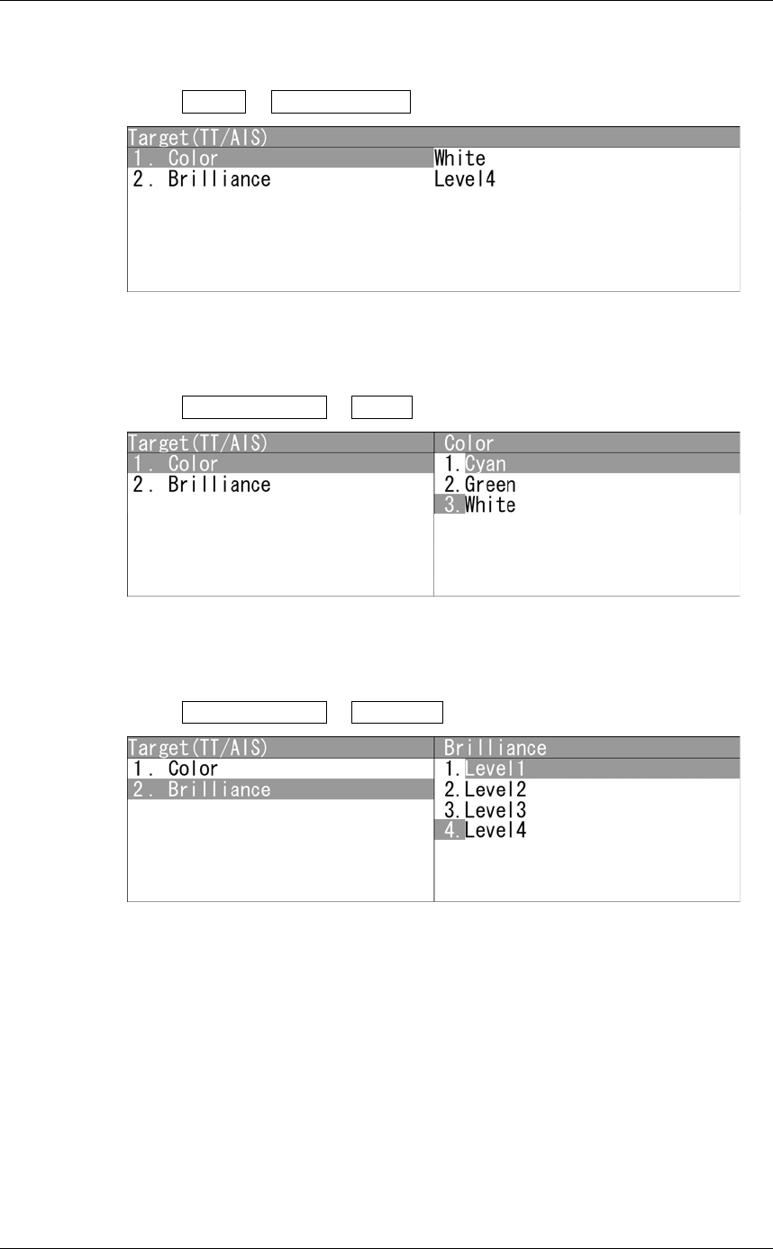
Target(TT/AIS)
Adjusts the colors of TT (tracked target)/AIS symbols.
1Open Day1 - Target(TT/AIS) .
"Target(TT/AIS)" menu appears.
z Display Color
1Open Target(TT/AIS) - Color .
"Color" menu appears.
z Display Brilliance
1Open Target(TT/AIS) - Brilliance .
"Brilliance" menu appears.

Chapter 2
OPERATIONS
2.12
DISPLAY COLOR SETTING
2-103
2
INSTRUCTION MANUAL
EBL/VRM/Parallel
Adjusts the colors of EBL/VRM/Parallel lines.
1Open Day1 - EBL/VRM/Parallel .
"EBL/VRM/Parallel" menu appears.
z Display Color
1Open EBL/VRM/Parallel - Color .
"Color" menu appears.
z Display Brilliance
1Open EBL/VRM/Parallel - Brilliance .
"Brilliance" menu appears.
Chapter 2
OPERATIONS
2.12
DISPLAY COLOR SETTING
2-104
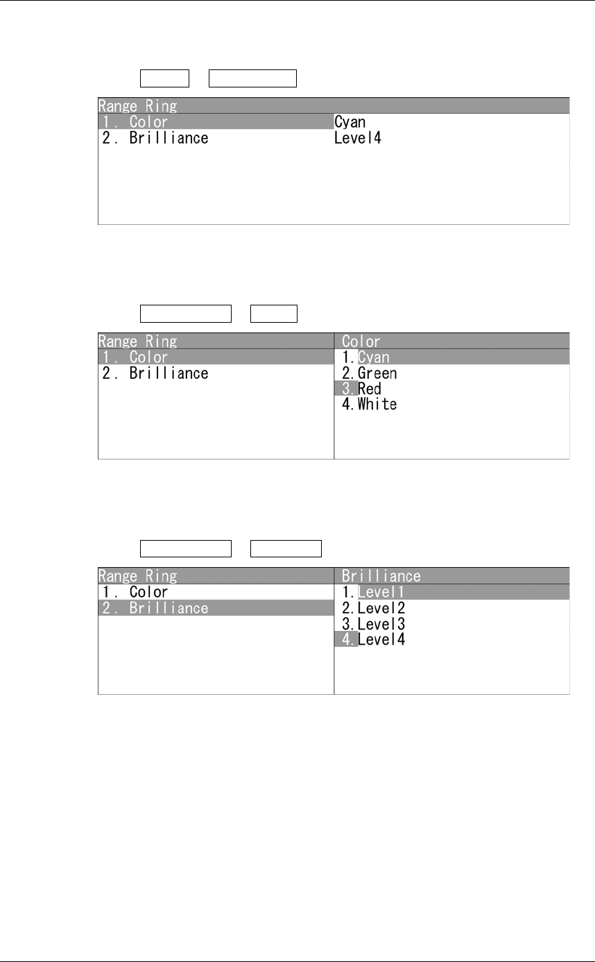
Range Ring
Adjusts the colors of range rings.
1Open Day1 - Range Ring .
"Range Ring" menu appears.
z Display Color
1Open Range Ring - Color .
"Color" menu appears.
z Display Brilliance
1Open Range Ring - Brilliance .
"Brilliance" menu appears.

Chapter 2
OPERATIONS
2.12
DISPLAY COLOR SETTING
2-105
2
INSTRUCTION MANUAL
Cursor
Adjusts the colors of cursors.
1Open Day1 - Cursor .
"Cursor" menu appears.
z Display Color
1Open Cursor - Color .
"Color" menu appears.
z Display Brilliance
1Open Cursor - Brilliance .
"Brilliance" menu appears.
Chapter 2
OPERATIONS
2.12
DISPLAY COLOR SETTING
2-106
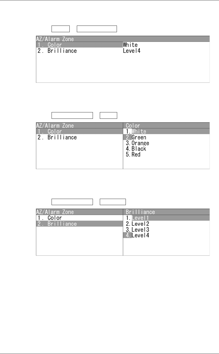
AZ/Alarm Zone
Adjusts the colors of AZ/Alarm Zone.
1Open Day1 - AZ/Alarm Zone .
"AZ/Alarm Zone" menu appears.
z Display Color
1Open AZ/Alarm Zone - Color .
"Color" menu appears.
z Display Brilliance
1Open AZ/Alarm Zone - Brilliance .
"Brilliance" menu appears.
Chapter 2
OPERATIONS
2.13
CONTROL SETTING
2-107
2
INSTRUCTION MANUAL
2.13 CONTROL SETTING
This function enables the setting of detail information about radar echo.
"Control" operations
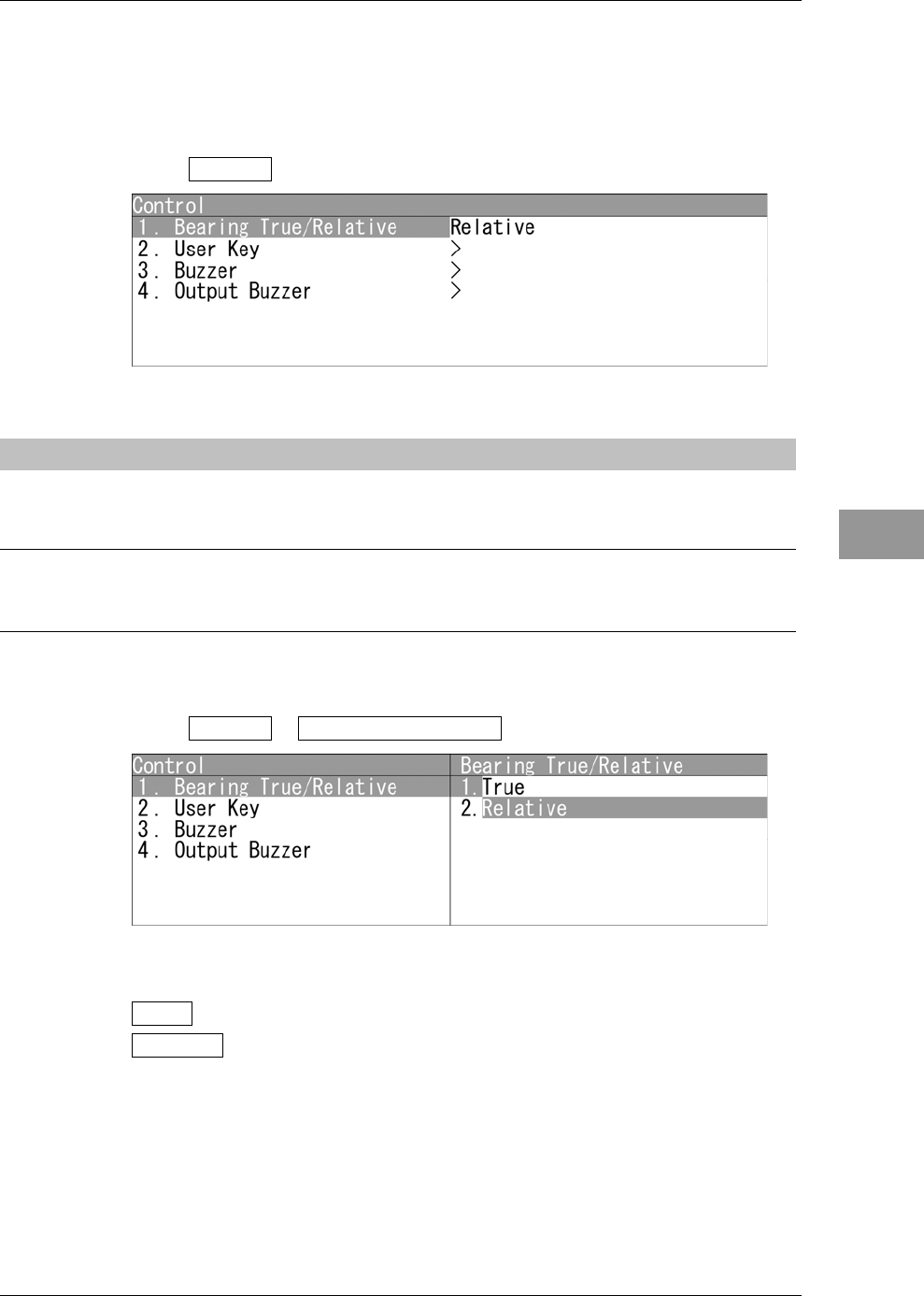
1Open Control from the Main Menu.
"Control" menu appears.
2.13.1 DISPLAYING TRUE/RELATIVE MOTION
Sets the bearing standards for the cursor, TT, AIS and MOB.
Reference:
Bearing signal and speed signal input are required to display true motion.
Setting Bearing
1Open Control - Bearing True/Relative .
"Bearing True/Relative" menu appears.
True : True bearing mode is selected.
Relative : Relative bearing mode is selected.
Chapter 2
OPERATIONS
2.13
CONTROL SETTING
2-108
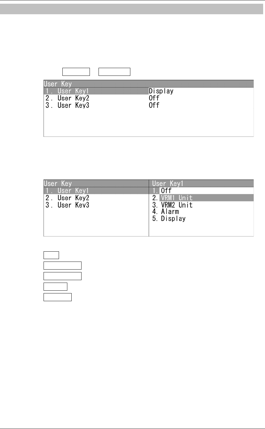
2.13.2 SETTING USER KEYS
Users can freely assign functions to the user keys.
When using this function, you can instantly open the menu screen of "VRM1 Unit",
"VRM2 Unit", "Alarm" and "Display".
"User Key" operations
1Open Control - User Key .
"User Key" menu appears.
Factory presetting
Sets functions that can be performed with the user keys.
User key items
Off : No function is assigned to this user key.
VRM1 Unit : The setting can be changed in VRM1 unit on the radar display.
VRM2 Unit : The setting can be changed in VRM2 unit on the radar display.
Alarm : Radar alarms can be set.
Display : Display can be set.
Operate the same way for the settings of "User Key2" and "User Key3".
Chapter 2
OPERATIONS
2.13
CONTROL SETTING
2-109
2
INSTRUCTION MANUAL
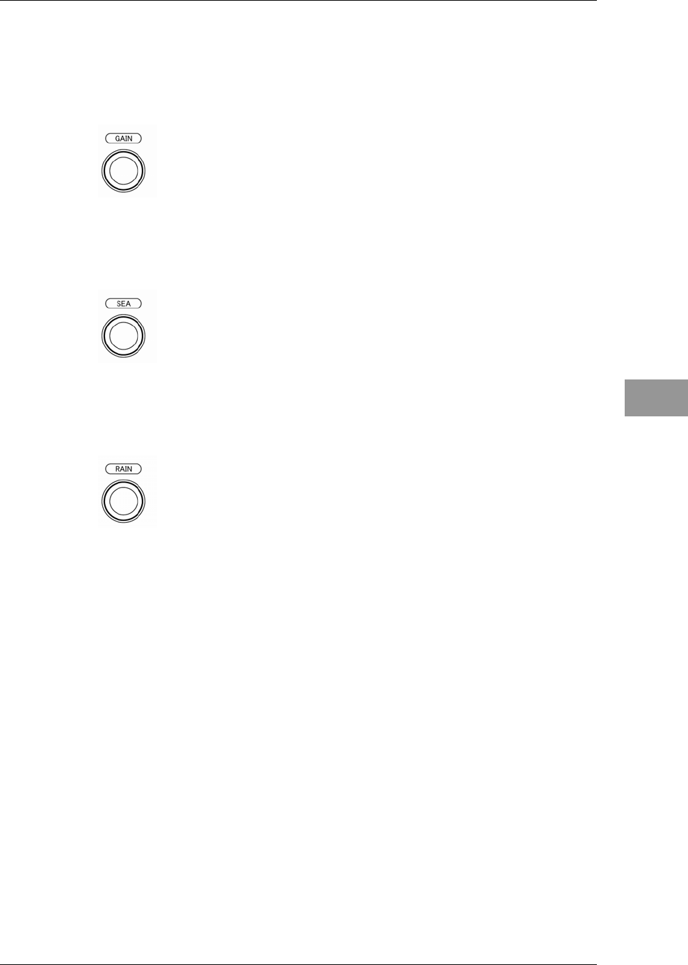
Using user keys
Operates as user keys.
z Displaying the menu assigned to the user key1
Hold down the [GAIN] control.
z Displaying the menu assigned to the user key2
Hold down the [SEA] control.
z Displaying the menu assigned to the user key3
Hold down the [RAIN] control.
Chapter 2
OPERATIONS
2.13
CONTROL SETTING
2-110
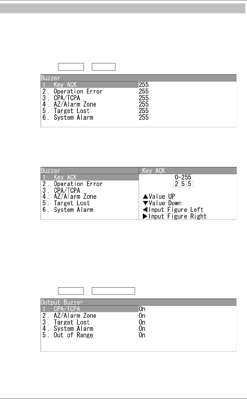
2.13.3 ADJUSTING BUZZER VOLUME
When an alarm goes off, the operation panel of the equipment produces a sound to notify
users of state changes.
Adjust the sound volume as follows.
"Buzzer" operations
1Open Control - Buzzer .
"Buzzer" menu appears.
Setting volume
Sets Key ACK volume.
Turn the [MULTI] control to adjust Key ACK volume.
Key ACK volume can be adjusted between 0 and 255.
When "0" is set, the volume is turned off.
Operate the same way for the other volume settings.
"Output Buzzer" operations
1Open Control - Output Buzzer .
"Output Buzzer" menu appears.
Chapter 2
OPERATIONS
2.13
CONTROL SETTING
2-111
2
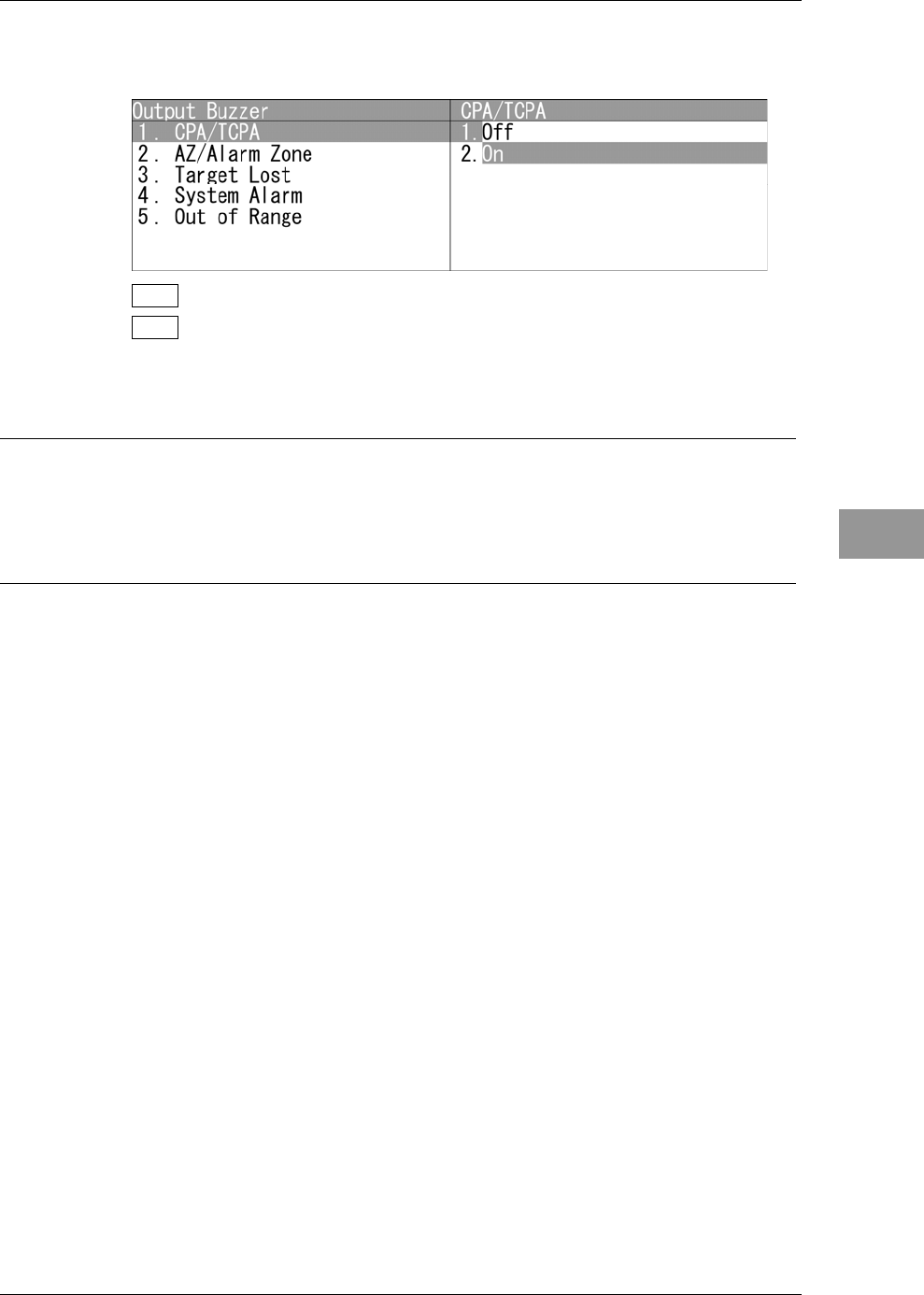
INSTRUCTION MANUAL
Setting CPA/TCPA
Sets the external buzzer for CPA/TCPA.
Off : Sets the external buzzer to Off.
On : Sets the external buzzer to On.
Operate the same way for the other external buzzer settings.
Reference:
For details of external buzzer connection, refer to "3.10 CONNECTING CONTACT
SIGNALS TO EXTERNAL BUZZERS/EXTERNAL DEVICES" in the INSTALLATION
MANUAL.
Chapter 2
OPERATIONS
2.14
FUNCTION KEY SETTINGS
2-112
2.14 FUNCTION KEY SETTINGS
"Function Setting" is provided for always obtaining the best radar video by storing
complex radar signal processing settings in the optimum status by use, and calling the
setting in accordance with the conditions for using the function.
Functions are factory-set for general use, and the settings can be fine adjusted by
operating the menu.
You can select one of 4 function modes. The factory presetting is shown below.
Function1 Setting: Standard Suitable for general monitoring.
Function2 Setting: Coast Useful for observing short-range videos.
Function3 Setting: Deepsea Suitable for general ocean navigation.
Function4 Setting: Fishnet Useful for small target.
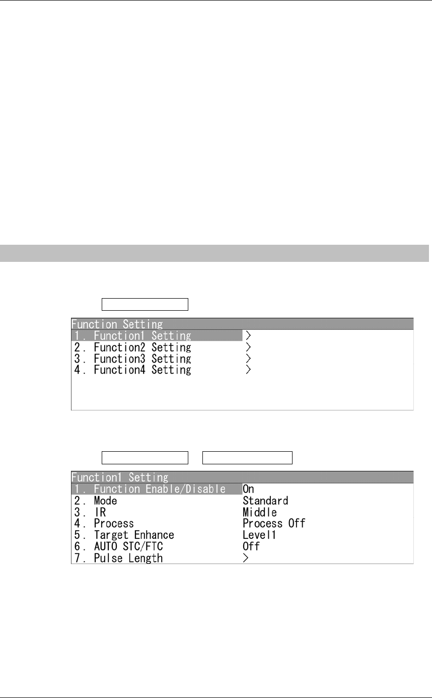
2.14.1 FUNCTION KEY OPERATIONS
"Function Setting" operations
1Open Function Setting from the Main Menu.
"Function Setting" menu appears.
2Open Function Setting - Function1 Setting .
"Function1 Setting" menu appears.

Chapter 2
OPERATIONS
2.14
FUNCTION KEY SETTINGS
2-113
2
INSTRUCTION MANUAL
Calling functions
1Press the [FUNC] key.
Each time you press the [FUNC] key, the setting is cyclically changed in order of:
Function off Function1 Setting Function2 Setting Function3 Setting
Function4 Setting Function off
The currently called function mode is indicated as the right of the screen.
z Calling function setting menu
1Hold down the [FUNC] key.
"Function Setting" menu appears when holding down the [FUNC] key.
Changing the setting
z Temporarily changing the setting
yWhen radar signal processing setting is changed by using the soft key or the menu
operation while function 1 to 4 is called, the change is temporarily reflected to the
operating state.
ySince this method does not change the memory contents, the new setting is deleted as
soon as another function is called.
yWhen the previous function is called again, operation is performed according to the
memory contents.
z Changing memory contents
yTo change the memory contents of functions 1 to 4, use [Function Setting] in the
Main Menu.

Chapter 2
OPERATIONS
2.14
FUNCTION KEY SETTINGS
2-114
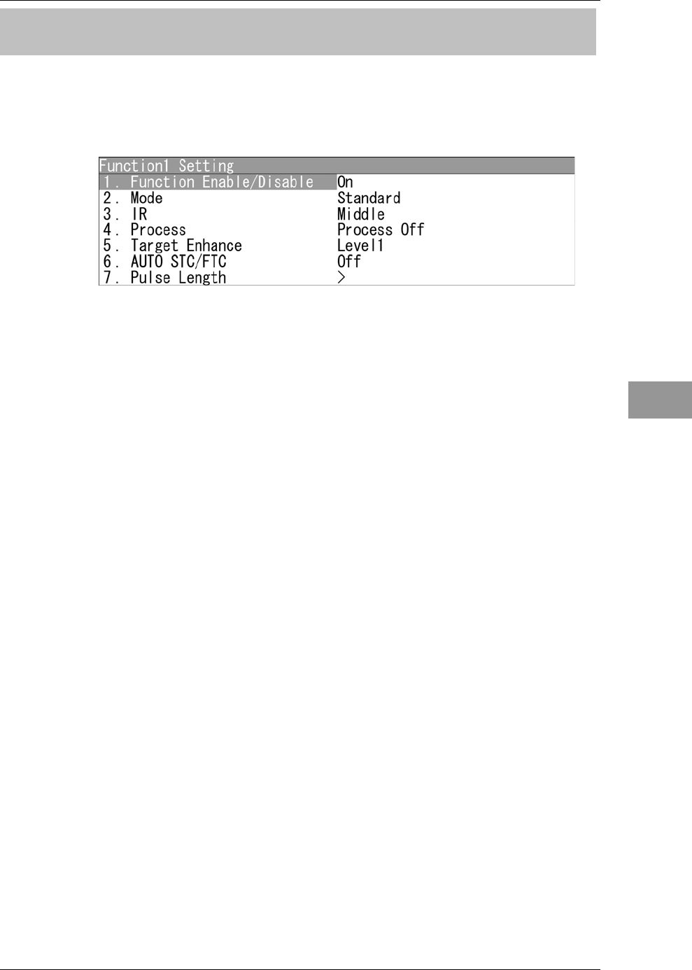
2.14.2 FUNCTION SETTING ITEMS
The function setting menu has the items below.
Item Description Setting
1. Function Enable/Disable The mode of FUNC key Off / On
2. Mode The setting of function mode
3. IR The setting of radar interference rejection level Off / Low / Middle / High
4. Process The setting of process level Off / 3Scan COREL / 4Scan COREL /
5Scan COREL / Remain / Peak Hold
5. Target Enhance The setting of target enhance level Off/Level1/Level2/Level3
6. AUTO STC/FTC The setting of automatic STC/FTC Off/AUTO STC/AUTO FTC
7. Pulse Length
0.5 NM Standard pulse length of 0.5 NM range SP/MP1
0.75/1NM Standard pulse length of 0.75 NM range SP/MP1
1.5NM Standard pulse length of 1.5/2 NM range SP/MP1
2/3/4NM Standard pulse length of 3/4 NM range MP1/MP2
6/8NM Standard pulse length of 6/8 NM range MP2/LP1
12/16NM Standard pulse length of 12/16 NM range LP1
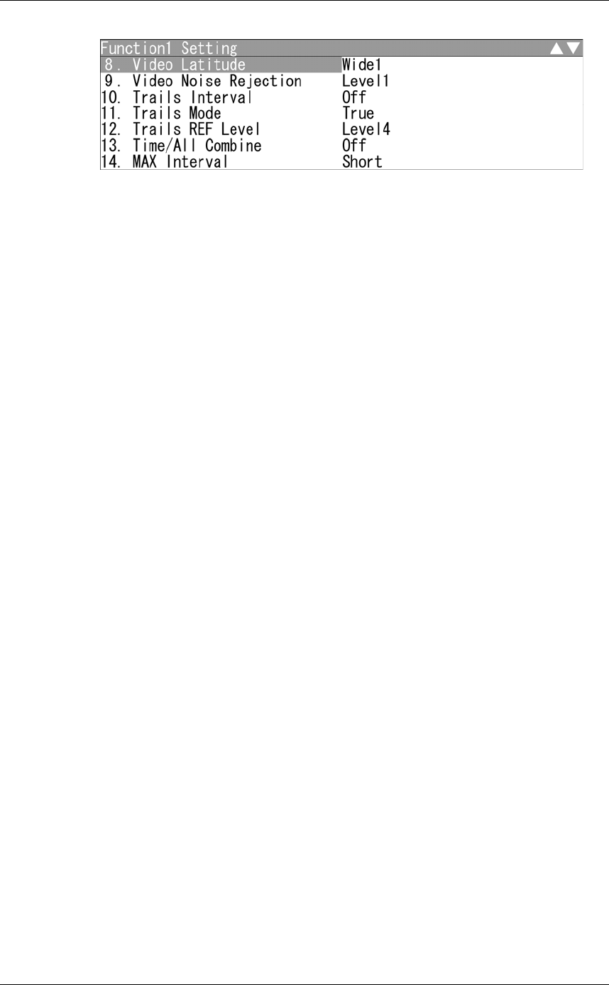
8. Video Latitude The dynamic range setting Narrow / Normal / Wide1 / Wide2
9. Video Noise Rejection The setting of video level not displayed on the radar
display.
Off / Level1 / Level2 / Level3
10. Trails Interval The setting of display time of radar trails Off / 15sec / 30sec / 1min / 2min / 3min /
4min / 5min / 6min / 10min / 15min / CONT
11. Trails Mode The setting of true/relative mode of radar trails TM / RM
12. Trails REF Level The setting of echo level which generates radar trails Level1 / Level2 / Level3 / Level4
13. Time/All Combine The setting of superimpose-display of time radar
trails and continuous radar trails
Off / On
14. MAX Interval The setting of maximum display time of radar trails Short / Middle / Long / Super Long
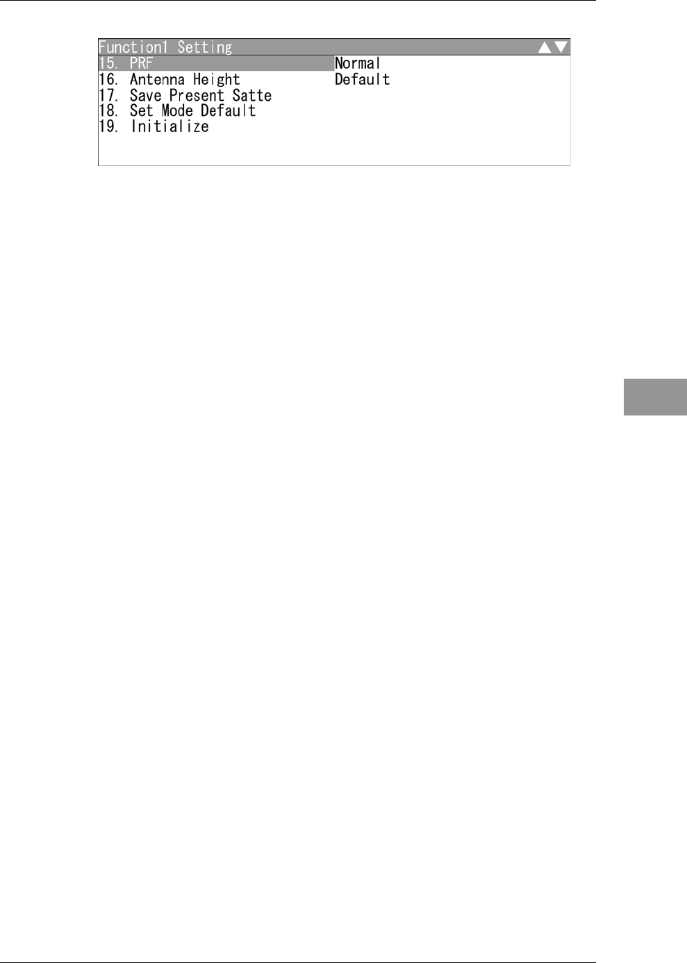
15. PRF The setting of data output cycle of scanner Normal/Economy / High Power
16. Antenna Height The setting of antenna height Default/㹼5m/5㹼10m/10㹼20m/20m㹼
17. Save Present State Saving the setting values of the other menu as those
of Function Setting
Yes/No
18. Set Mode Default Setting the current Function Setting as the default
settings
Yes/No
19. Initialize Initializing the value of Function Setting Yes/No
Chapter 2
OPERATIONS
2.14
FUNCTION KEY SETTINGS
2-115
2
INSTRUCTION MANUAL
2.14.3 OVERVIEW OF FUNCTION SETTING ITEM
OPERATIONS
The following outlines the operation of each function selected from the function setting
menu.
From "Function Enable/Disable" to "Pulse Length"
z Function Enable/Disable
If "Function Enable/Disable" is set to "Off", this mode is not displayed when switching
operation mode of function key.
z Mode
ySelects the function name to be indicated at the lower left of the radar display when
the function is selected.
yWhen the setting is changed back to the factory setting, the initial value of the
selected mode is called.
yThe following 12 modes are provided:
Standard: Use this mode for general purpose. This is suitable to monitor a
relatively short range.
Coast: Use this mode to monitor a relatively short range, for example,
bays and coasts where many boats and ships are running.
(Importance is attached to resolution.)
Deepsea: Use this mode to monitor a relatively long range, for example, the
open sea.
(Importance is attached to long-range sensitivity.)
Fishnet: Use this mode to detect small targets such as fishnets of round
haul netters hidden by sea clutter returns. (Importance is attached
to sea clutter suppression, and sensitivity to moving targets
lowers.)
Storm: Use this mode when many rain/snow clutter returns or sea clutter
returns are detected in stormy weather. (Importance is attached to
rain/snow clutter and sea clutter suppression, and sensitivity
slightly lowers.)

Chapter 2
OPERATIONS
2.14
FUNCTION KEY SETTINGS
2-116
Bonden: Use this mode when rain/snow clutter which cannot to be
suppressed is strong, such as a lot of floats of fixed net around the
ship.
Rain: Use this mode when sea clutter is not strong but rain/snow clutter
is strong. (Importance is attached to rain/snow clutter suppression,
and sensitivity slightly lowers.)
US River: Use this mode when adjusting the functions mainly suitable for
rivers in the United States.
Use this mode to reduce sea clutter returns (less effective than EU
river setting).
Long: Use this mode to detect small targets at relatively long distance in
the open sea.
EU River: Use this mode when adjusting the functions mainly suitable for
rivers in Europe.
Use this mode to reduce sea clutter returns.
User1: General mode used when the nine modes above are not
applicable.
User2: General mode used when the nine modes above are not
applicable.
z IR (Interference rejection)
Operate the same way for the interference rejection settings in the menu.
For details of operations, see Section "■ Setting Radar Interference Rejection" of "2.9
RADAR ECHO SETTINGS".
z Process
Operate the same way for the process settings in the menu.
For details of operations, see Section "■ Process" of "2.9 RADAR ECHO SETTINGS".
z Target Enhance
Operate the same way for the target enhance settings in the menu.
For details of operations, see Section "■ Setting for Enhancing Targets" of "2.9 RADAR
ECHO SETTINGS".

Chapter 2
OPERATIONS
2.14
FUNCTION KEY SETTINGS
2-117
2
INSTRUCTION MANUAL
z AUTO STC/FTC (Automatic clutter suppression)
yDetects unwanted waves such as rain/snow clutter and sea clutter and automatically
suppresses them.
yWhen the sea state or weather changes, this function automatically performs
suppression processing in accordance with the situation.
ySuppression processing is not full automatic, and requires the operator to control the
afterimages of unwanted waves.
yTo control the afterimage of sea clutter, use the [SEA] control.
yTo control the afterimage of rain/snow clutter, use the [RAIN] control.
yIn areas where the density of unwanted waves is low, unwanted waves may remain
being judged as targets. Thus, use the automatic clutter suppression mode together
with the video process mode.
yCharacteristics of the automatic clutter suppression function:
Off: Disables the automatic clutter suppression function.
Select "Off" when rain/snow clutter and sea clutter are not strong
or when the ship is in a bay.
AUTO STC: Automatically detects the strength of sea clutter, and performs the
most suitable sea clutter suppression processing.
Even when the strength of sea clutter varies depending on the wind
direction, AUTO STC performs the most suitable suppression
processing.
Land like islands can be displayed naturally.
Since rain clouds outside sea clutter areas are recognized as land,
there is no effect of suppressing rain/snow clutter.
Use the [RAIN] control to set the rain/snow clutter suppression
function.
AUTO FTC: Along with AUTO STC, this function automatically detects the
strength of rain/snow clutter, and performs the most suitable
rain/snow clutter suppression processing.
Since land is recognized as rain clouds, land videos become
obscure.
z Pulse Length
ySets the standard transmitter pulse length in each range.
yWhen the range is called, the pulse length is used.
Chapter 2
OPERATIONS
2.14
FUNCTION KEY SETTINGS
2-118
From "Video Latitude" to "MAX Interval"
z Video Latitude
Operate the same way for the video latitude settings in the menu.
For details of operations, refer to "2.9.5 VIDEO LATITUDE".
z Video Noise Rejection
Operate the same way for the video latitude settings in the menu.
For details of operations, refer to "2.9.6 VIDEO NOISE REJECTION".
z Trails Interval
Operate the same way for the trail interval settings in the soft key menu.
For details of operations, refer to "2.7.5 DISPLAYING OTHER SHIP'S TRACKS
(RADAR TRAILS)".
z Trails Mode
Operate the same way for the trail interval settings in the soft key menu.
For details of operations, refer to "2.7.5 DISPLAYING OTHER SHIP'S TRACKS
(RADAR TRAILS)".
z Trails REF Level
Operate the same way for the trail interval settings in the soft key menu.
For details of operations, refer to "2.7.5 DISPLAYING OTHER SHIP'S TRACKS
(RADAR TRAILS)".
z Time/All Combine
Operate the same way for the trail interval settings in the soft key menu.
For details of operations, refer to "2.7.5 DISPLAYING OTHER SHIP'S TRACKS
(RADAR TRAILS)".
z MAX Interval
Operate the same way for the trail interval settings in the menu.
For details of operations, refer to "2.10 RADAR TRAIL LENGTH SETTING".
Chapter 2
OPERATIONS
2.14
FUNCTION KEY SETTINGS
2-119
2
INSTRUCTION MANUAL
From "PRF" to "Initialize"
z PRF
Operate the same way for the scanner settings in Adjust Menu.
For details of operations, see Section "4.6 SCANNER" of INSTALLATION MANUAL.
z Antenna Height
yChanges the antenna height setting.
yThe STC/FTC curve is changed.
Default: Activates the general signal processing mode.
-5m: Set the antenna height under 5 m.
5-10m: Set the antenna height 5m to 10m.
10-20m: Set the antenna height 10 m to 20 m.
20m-: Set the antenna height over 20 m.
z Save Present State
Registers the currently used settings as function settings.
z Set Mode Default
Sets the initial value of a selected function setting mode. Select this item to change the
current function mode to the initial value.
z Initialize
Sets the function settings to the factory-set values. Select this item to change all the
function settings to the factory-set values.
Chapter 2
OPERATIONS
2.15
SETTING TT/AIS
2-120
2.15 SETTING TT/AIS
This section describes the operations of TT and AIS.
2.15.1 COLLISION AVOIDANCE
Problems of Collision Avoidance in Navigation
Marine collision avoidance is one of the problems that have been recognized from of old.
Now, it will be described briefly who the collision avoidance is positioned among the
navigational aid problems.
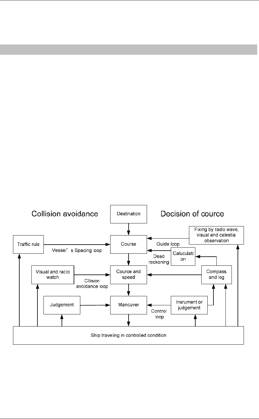
The navigation pattern of all mobile craft constitutes a system with some closed loops
regardless of the media through which the mobile craft travels, whether air, water, the
boundary between air and water, or space. This pattern consists of two closed loops in
principle, one of which is a collision with another mobile craft and the other is a loop of
finding a right and safe way to reach a predeterminate destination.
Fig. 2.15-1 shows the conceptual diagram of navigation pattern by MR. E.W. Anderson.
The closed loop of collision avoidance is shown on the left side and the closed loop of
finding a right course on the right side.
Fig. 2.15-1 Navigation Pattern
Chapter 2
OPERATIONS
2.15
SETTING TT/AIS
2-121
2
INSTRUCTION MANUAL
Marine Accidents and Collisions
Among marine accidents, collision accidents have been highlighted as the tonnages and
speeds of ships become higher along with the increase in traffic at sea.
If a tanker carrying dangerous articles such as crude oil collides with any other vessel,
then not only the vessels involved with the accident but other vessels in the vicinity, port
facilities, inhabitants in the coastal area as well as marine resources may also suffer
immeasurable damages and troubles.
Collision accidents have a high percentage of the marine accidents that have occurred in
recent years. To cope with these problems, any effective measures are needed and some
equipment to achieve collision avoidance requirements have been developed at rapid strides.
Basic Concept of Collision Avoidance
There are two aspects in collision avoidance: collision prediction and avoidance.
Collision prediction is to predict that two or more vessels will happen to occupy the
same point at the same time, while collision avoidance is to maneuver vessels not to
occupy the same point at the same time.
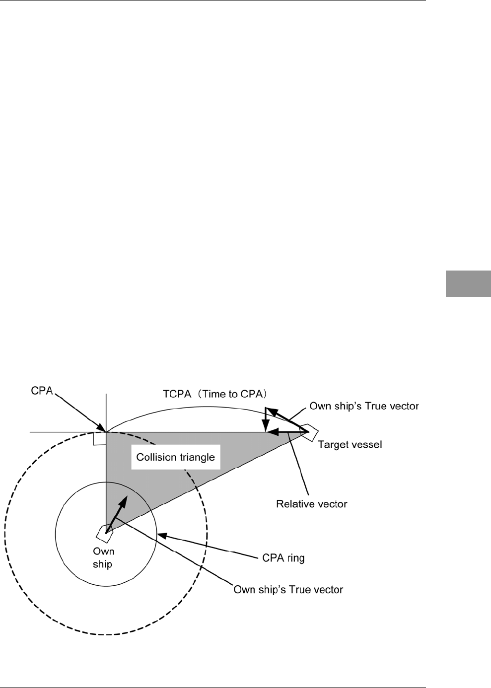
In practical operation of vessels, a spot of collision has to be deemed to be a single point
but a closed zone. This closed zone is conceptually defined as a CPA (Closest Point of
Approach).In collision prediction, the time to be taken until a ship reaches the CPA is
defined as a TCPA (Time to CPA). Fig. 2.15-2 shows a diagram called "Collision
Triangle".
Fig. 2.15-2 Collision Triangle
Chapter 2
OPERATIONS
2.15
SETTING TT/AIS
2-122
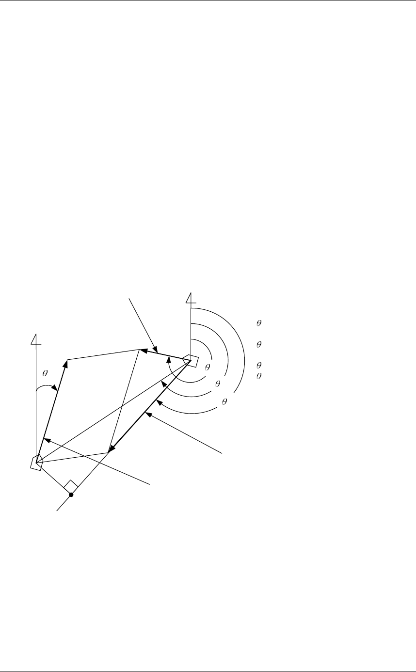
Relative Vector and True Vector
From two points of view, collision prediction and avoidance, it is necessary to obtain the
relative vector of other ship for prediction and the true vector of other ship for collision
avoidance in order to grasp other ship's aspect.
The relationship between the relative vector and true vector is shown in Fig. 2.15-3.
Furthermore, the meanings of both vectors are described.
Both rough CPA and TCPA can be obtained easily from the relative speed vector of
other ship. This method has an advantage that the risks of collision with all other ships
within the radar range can be seen at a glance. On the other hand, the course and speed
of other ship can easily be obtained from its true speed vector, enabling other ship's
aspect to be seen at a glance. Thus, the aspects of other ships (transverse, outsail, parallel
run, reverse run, etc. ) as described in the act of prevention of collision at sea can be
readily grasped. If there is a risk of collision with other ship, the operator can determine
which rule to be applied and how to operate own ship.
Fig. 2.15-3 Relative Vector and True Vector
N
T
R
A
O
Vo
VR
VT
VO: Own ship's speed
O: Own ship's course
VT: Other ship's true speed
T: Target ship's true course
VR: Target ship's relative speed
R: Target ship's relative course
A: Aspect
Relative vector
Target ship true vector
N
CPA
Own ship true vector
Radar and Collision Avoidance
Radar is still playing an important roll for collision prevention and positioning.
A plotter is used to further enhance the radar functionality. The plotter is capable of
plotting other positions of other ships in 3 to 6 minute intervals to monitor their
movement. The plots of other ships represent their tracks relative to own ship, and it is
shown whether there is a risk of collision, namely CPA and TCPA can be obtained. This
method using a plotter is fairly effective, but the number of target ship, which are
manually plotted, is limited and it takes several minutes to measure those.
Chapter 2
OPERATIONS
2.15
SETTING TT/AIS
2-123
2
INSTRUCTION MANUAL
2.15.2 PREPARATION
Initializes Tracking Target and AIS Function
"Target" operations
1Open Target from the Main Menu.
"Target" menu appears.
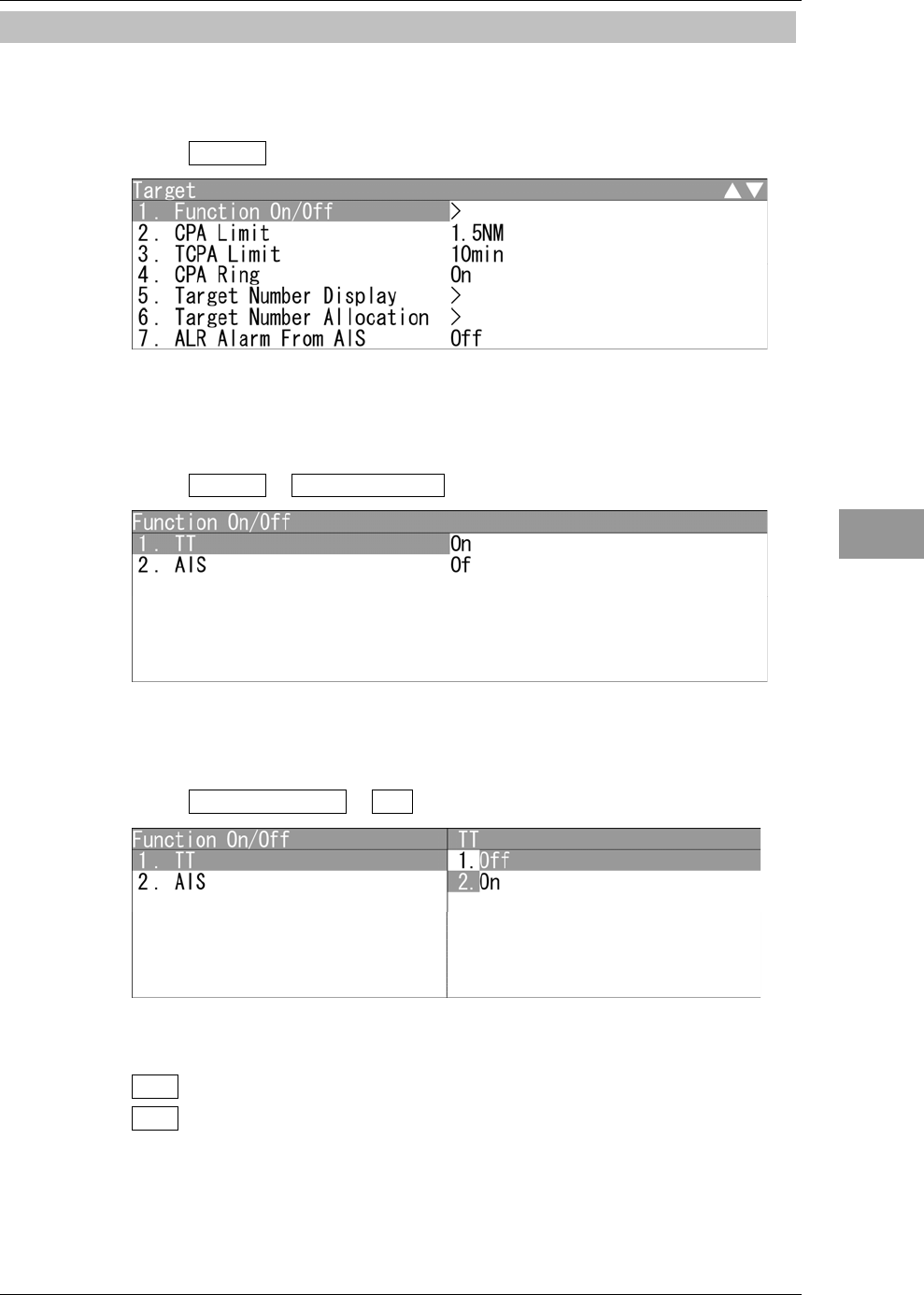
Turning On/Off the Function
Turns on/off tracking target and AIS function.
1Open Target - Function On/Off .
"Function On/Off" menu appears.
z Turning on/off the tracking target function
1Open Function On/Off - TT .
"TT" menu appears.
Off : Turns off the TT function.
On : Turns on the TT function.
Chapter 2
OPERATIONS
2.15
SETTING TT/AIS
2-124
z Turning on/off the AIS function
1Open Function On/Off - AIS .
"AIS" menu appears.
Off : Turns off the AIS function.
On : Turns on the AIS function.
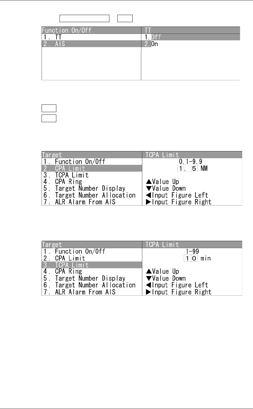
Setting Collision Decision Criteria
Set and check collision decision criteria before operating.
Input the CPA Limit value.
Turn the [MULTI] control to set the CPA Limit value.
The CPA Limit value can be set between 0.1 and 9.9 NM.
Input the TCPA Limit value.
Turn the [MULTI] control to set the TCPA Limit value.
The TCPA Limit value can be set between 1 and 99 min.
Chapter 2
OPERATIONS
2.15
SETTING TT/AIS
2-125
2
INSTRUCTION MANUAL
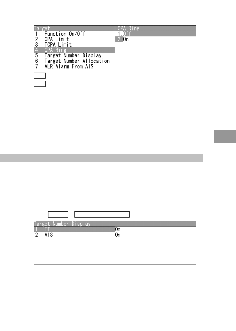
Setting CPA Ring
Sets the CPA ring display.
Off : The CPA ring is not displayed.
On : The CPA ring is displayed.
While the distance of the specified CPA Limit value is used as the radius, the CPA
ring is displayed with a white circle of which center is the own ship's position.
Reference:
The CPA ring is not displayed when the true vector mode is selected.
See "2.7.4 SETTING VECTORS" to change the settings.
2.15.3 SETTING TARGET NUMBER DISPLAY
A target ID number is a value displayed beside the target symbol or AIS symbol.
These numbers are assigned to targets in acquisition order. The numbers 1 to 10 are
automatically assigned. Each target is identified by the assigned ID number until it is lost
or its acquisition is canceled.
"Target Number Display" operations
1Open Target - Target Number Display .
"Target Number Display" menu appears.
Chapter 2
OPERATIONS
2.15
SETTING TT/AIS
2-126
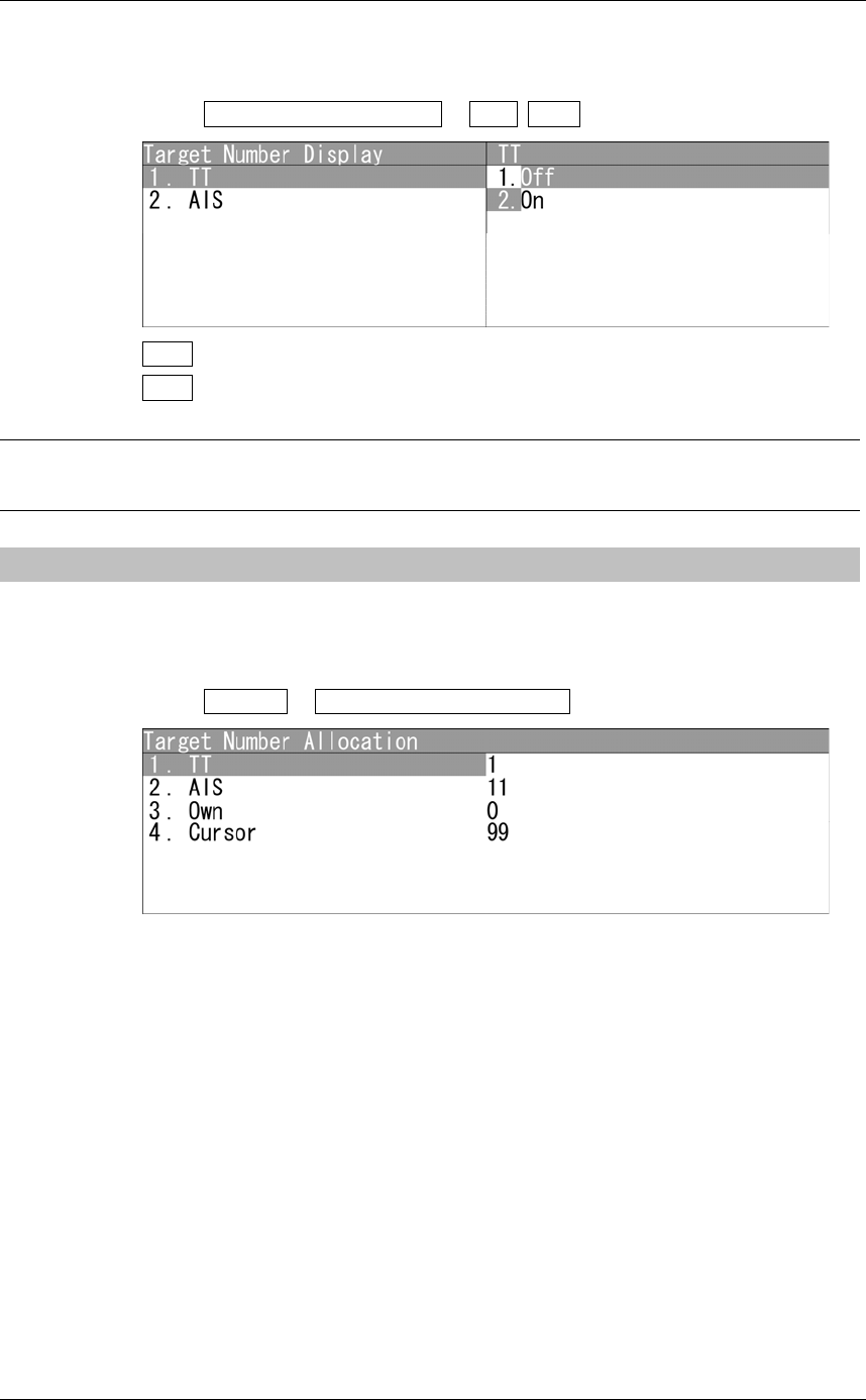
Turning On/Off the Number of Tracking Target and AIS
Turns on/off the number of tracking target and AIS symbol.
1Open Target Number Display - TT AIS .
Off : Target numbers of TT/AIS are not displayed.
On : Target numbers of TT/AIS are displayed.
Reference:
An ID number is always displayed for only targets with which numeric data is displayed.
2.15.4 SETTING TARGET NUMBER ALLOCATION
The start number of target can be specified for the target symbol or AIS symbol.
"Target Number Allocation" operations
1Open Target - Target Number Allocation .
"Target Number Allocation" menu appears.
Chapter 2
OPERATIONS
2.15
SETTING TT/AIS
2-127
2
INSTRUCTION MANUAL
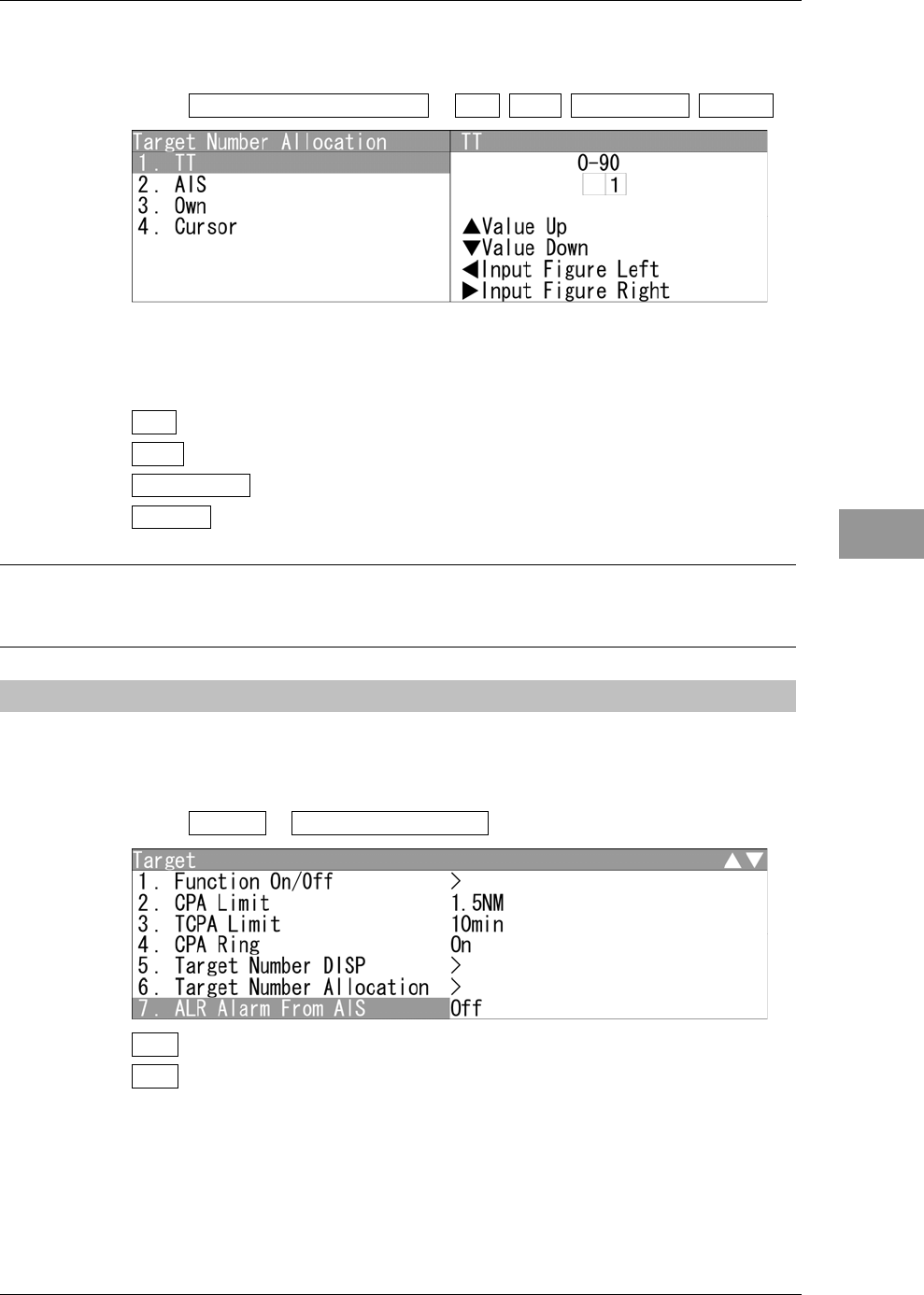
Target Number Allocation
Turns on/off the start number of target for tracking.
1Open Target Number Allocation - TT AIS Own Ship's Cursor .
Turn the [MULTI] control to set the start number of target.
Operate the same way for the other target numbers.
TT : The start number of target can be adjusted between 0 and 90.
AIS : The start number of target can be adjusted between 0 and 50.
Own Ship's : The start number of target can be adjusted between 0 and 99.
Cursor : The start number of target can be adjusted between 0 and 99.
Reference:
Set the target number of TT/AIS not to overlap each other.
2.15.5 SETTING AIS ALARM
Sets the display of NMEA ALR sentence received from AIS.
Setting AIS Alarm
1Open Target - ALR Alarm From AIS .
Off : ALR alarm is turned off.
On : ALR alarm is turned on.
Chapter 2
OPERATIONS
2.15
SETTING TT/AIS
2-128
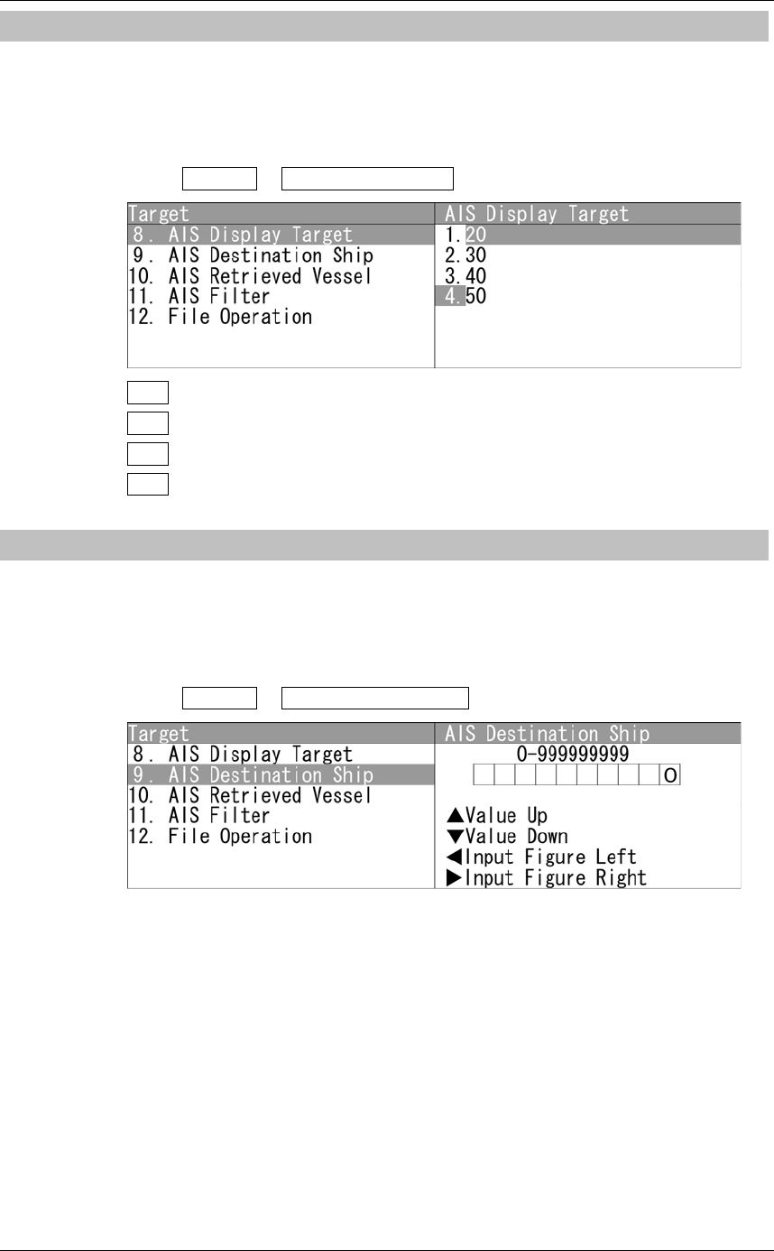
2.15.6 SETTING AIS DISPLAY TARGET
Set the number of AIS display targets.
Set this to get a better look at the screen by limiting the number of AIS symbols.
Setting AIS Display Target
1Open Target - AIS Display Target .
20 : The number of AIS display targets is set to 20.
30 : The number of AIS display targets is set to 30.
40 : The number of AIS display targets is set to 40.
50 : The number of AIS display targets is set to 50.
2.15.7 SETTING AIS DESTINATION SHIP (DirecTrakTM)
AIS destination ship is the function to display the user-specified ship as the destination.
If MMSI of AIS target is set, the destination ship can be specified.
Setting AIS Destination Ship
1Open Target - AIS Destination Ship .
Turn the [MULTI] control to set MMSI.
MMSI can be adjusted between 0 and 999999999.
Chapter 2
OPERATIONS
2.15
SETTING TT/AIS
2-129
2
INSTRUCTION MANUAL
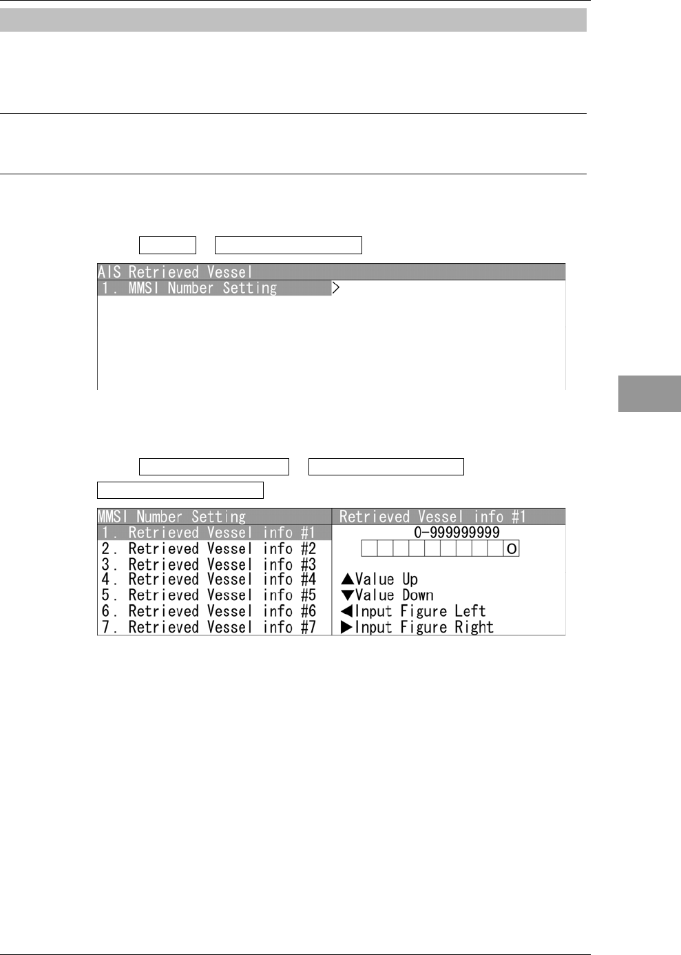
2.15.8 SETTING AIS RETRIEVED VESSEL
AIS retrieved vessel is the function to preferentially display the user-specified ship.
If MMSI of AIS target is set, the retrieved vessel can be specified.
Reference:
AIS retrieved vessel can be set up to 10 vessels.
"AIS Retrieved vessel" operations
1Open Target - AIS Retrieved Vessel .
"AIS Retrieved Vessel" menu appears.
MMSI Number Setting
1Open AIS Retrieved Vessel - MMSI Number Setting -
Retrieved Vessel info #1 .
Turn the [MULTI] control to set MMSI number.
MMSI number can be adjusted between 0 and 999999999.
Operate the same way for the other retrieved vessels.
Chapter 2
OPERATIONS
2.15
SETTING TT/AIS
2-130
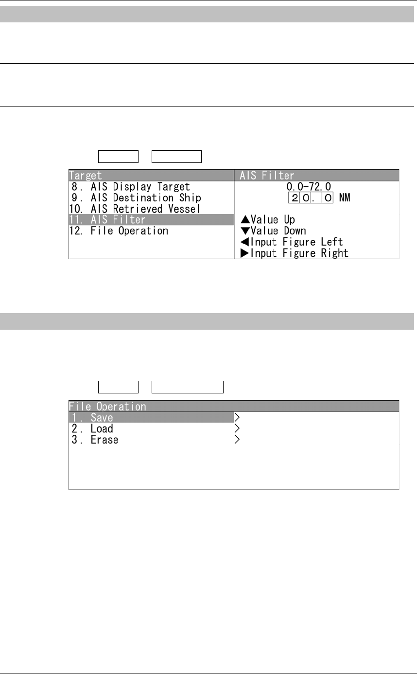
2.15.9 SETTING AIS FILTER
Sets the range for AIS filter.
Reference:
For details of AIS filter, refer to "2.7.22 SETTING AIS FILTER".
Setting AIS Filter
1Open Target - AIS Filter .
Turn the [MULTI] control to set the range for AIS filter.
The range can be set between 0 and 72.0 NM.
2.15.10 FILE OPERATION
The stored MMSI number setting of AIS retrieved vessel is output via USB.
File Operation
1Open Target - File Operation .
"File Operation" menu appears.
Chapter 2
OPERATIONS
2.15
SETTING TT/AIS
2-131
2
INSTRUCTION MANUAL
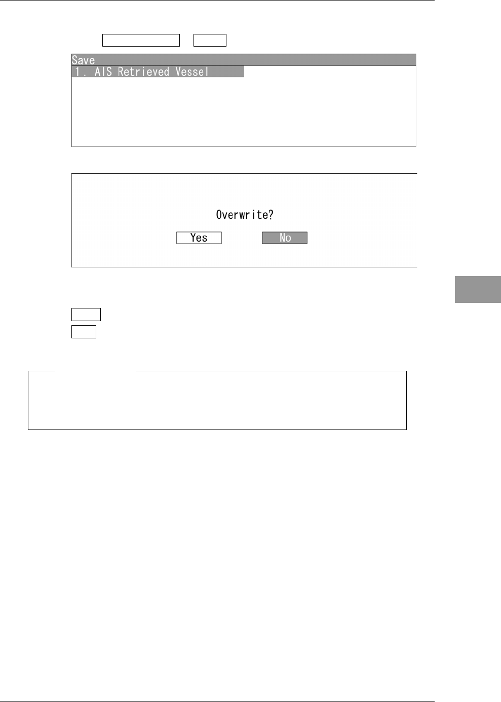
Saving MMSI number setting
1Open File Operation - Save .
"Save" menu appears.
When opening "AIS Retrieved vessel", the dialog box "Overwrite?" appears.
Yes : Saves via USB.
No : Does not save via USB.
Note:
z After saving data to a USB memory, move the data to a storage, such as PC,
that can store the data with password to prevent data leakage.
When selecting "Yes", "Processing." appears on the radar screen.
After saving is finished, the screen returns to "Save" menu.
When selecting "No", the screen returns to "Save" menu.
Chapter 2
OPERATIONS
2.15
SETTING TT/AIS
2-132
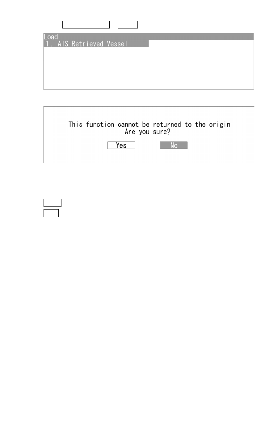
Loading MMSI number setting
1Open File Operation - Load .
"Load" menu appears.
When opening "AIS Retrieved vessel", the dialog box "This function cannot be
returned to the origin. Are you sure?" appears.
Yes : Loads via USB.
No : Does not load via USB.
When selecting "Yes", "Processing." appears on the radar screen.
After saving is finished, the screen returns to "Load" menu.
After saving is finished, the screen returns to "Load" menu.
Chapter 2
OPERATIONS
2.15
SETTING TT/AIS
2-133
2
INSTRUCTION MANUAL
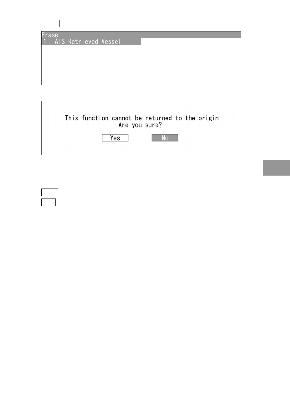
Clearing MMSI number setting
1Open File Operation - Erase .
"Erase" menu appears.
When opening "AIS Retrieved vessel", the dialog box "This function cannot be
returned to the origin. Are you sure?" appears.
Yes : Erases data via USB.
No : Does not erase data via USB.
When selecting "Yes", "Processing." appears on the radar screen.
After saving is finished, the screen returns to "Erase" menu.
When selecting "No", the screen returns to "Erase" menu.
Chapter 2
OPERATIONS
2.16
SETTING DETECTION LEVELS OF RADAR ALARM
2-134
2.16 SETTING DETECTION LEVELS OF RADAR
ALARM
Detection levels can be set to issue alarms from the radar alarm.
Reference:
For details of display settings for radar alarm, see "2.7.8 DISPLAYING THE RADAR
ALARM AND AUTOMATIC ACQUISITION OPERATIONS".
"RADAR Alarm" operations
1Open Main Menu - RADAR Alarm .
"RADAR Alarm" menu appears.
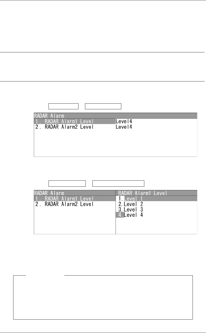
Setting Detection Level
1Open RADAR Alarm - RADAR Alarm1 Level .
"RADAR Alarm1 Level" menu appears.
Select Level1, Level2, Level3 or Level4.
Operate the same way for the settings of "RADAR Alarm2 Level".
Note:
z Select Level1, Level2, Level3 or Level4 for alarm level.
When setting to lower level of detection, the alarm operates for weaker targets.
When setting to higher level of detection, be careful because the alarm may not
operate properly.
Chapter 2
OPERATIONS
2.17
PLOTTER UNIT
2-135
2
INSTRUCTION MANUAL
2.17 PLOTTER UNIT
Sets the plotter unit.
"Plot" operations
1Open Main Menu - Plot .
"Plot" menu appears.
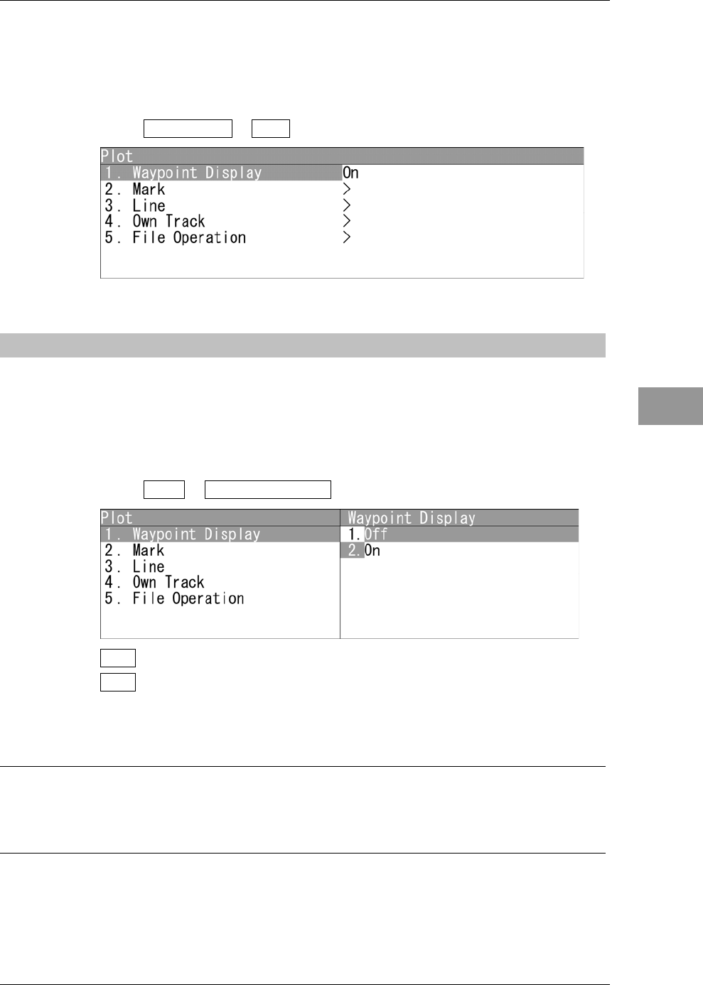
2.17.1 DISPLAYING WAYPOINT MARKS
When waypoint information is received from the navigation equipment, the waypoint
mark appears on the radar display.
"ۑ" is indicated as the waypoint mark on the radar display.
Setting for Waypoint Display
1Open Plot - Waypoint Display .
Off : The waypoint marks are not displayed.
On : The waypoint marks are displayed.
Waypoint marks are displayed only when NMEA/RMB/BWC sentences are used to
receive Waypoint information.
Reference:
To display Numerical INFO of waypoint, see "4.13.7 LOCATION CHANGE" in
"INSTALLATION MANUAL".
Chapter 2
OPERATIONS
2.17
PLOTTER UNIT
2-136
2.17.2 SETTING MARK FUNCTIONS
Sets the mark functions.
"Mark" operations
1Open Plot - Mark .
"Mark" menu appears.
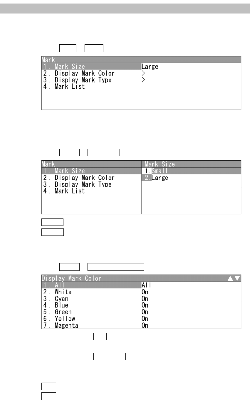
Setting Mark Symbol Size
Sets the mark symbol size.
1Open Mark - Mark Size .
Small : Small marks are used.
Large : Large marks are used.
Display Mark Color
Displays the marks with the specified color.
1Open Mark - Display Mark Color .
When "All" is set to All :
The setting of "All" is prior to individual settings.
When "All" is set to Individual :
Individual settings are prior to the setting of "All".
On : Displays the marks with the specified color.
Off : Does not display the marks with the specified color.
Chapter 2
OPERATIONS
2.17
PLOTTER UNIT
2-137
2
INSTRUCTION MANUAL
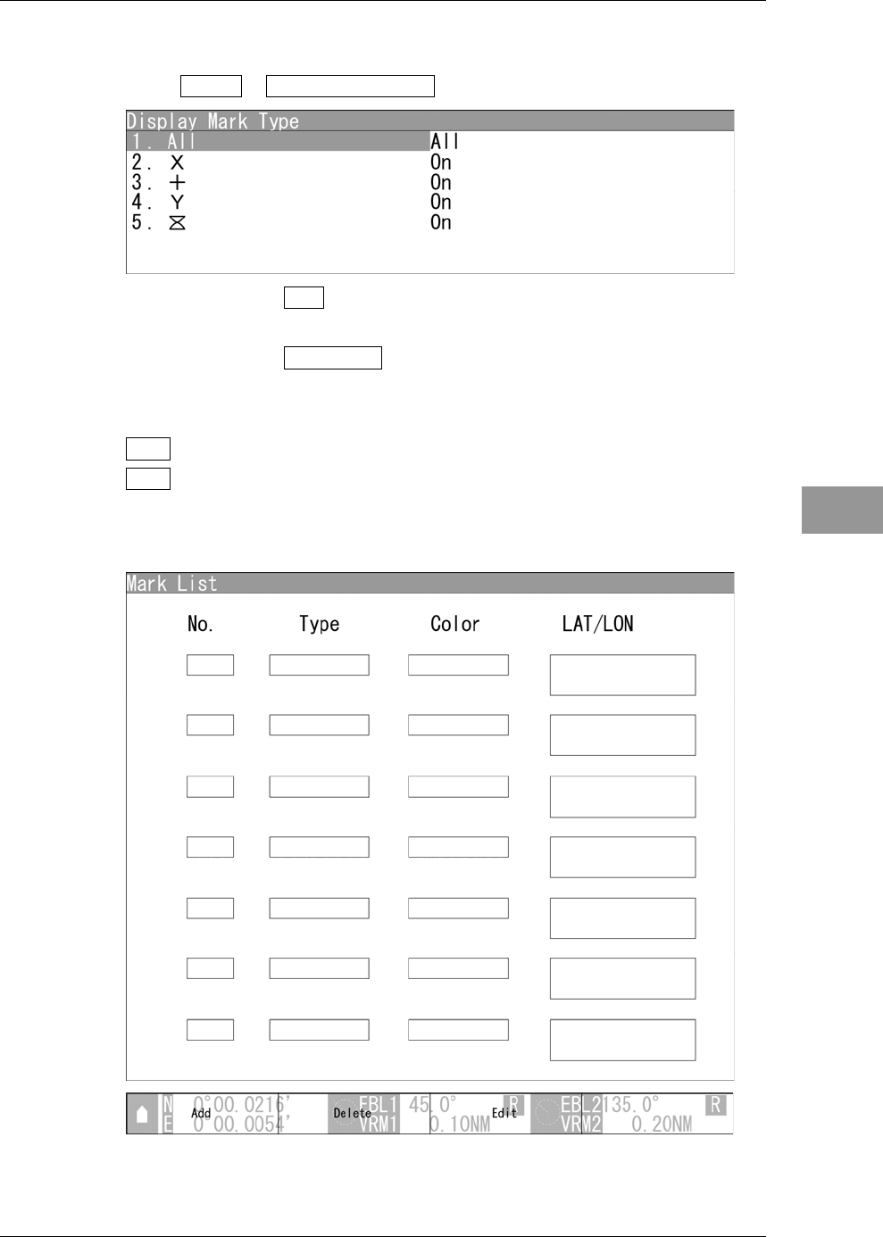
Display Mark Type
Displays the marks with the specified type.
1Open Mark - Display Mark Type .
When "All" is set to All :
The setting of "All" is prior to individual settings.
When "All" is set to Individual :
Individual settings are prior to the setting of "All".
On : Displays the marks with the specified type.
Off : Does not display the marks with the specified type.
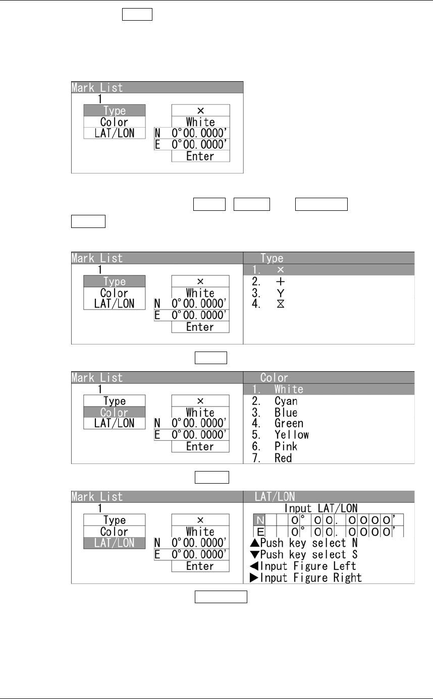
Mark List
Displays the mark list screen.
Chapter 2
OPERATIONS
2.17
PLOTTER UNIT
2-138
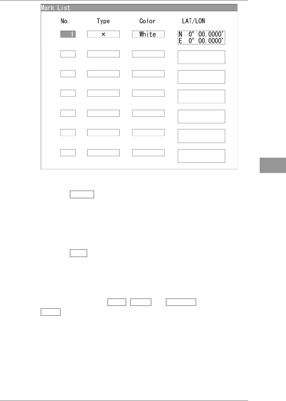
Soft key 1: Add
Creates marks.
Press the soft key 1 "Add".
"Add" menu appears.
Use the cursor keys to input Type , Color and LAT/LON , then press the
Enter .
Use the cursor keys to select the Type .
Use the cursor keys to select the Color .
Use the cursor keys to select the LAT/LON .
Chapter 2
OPERATIONS
2.17
PLOTTER UNIT
2-139
2
INSTRUCTION MANUAL
A new mark appears in the mark list.
Soft key 2: Delete
Erases marks.
Turn the [MULTI] control to select a mark list.
Press the soft key 2 "Erase" to erase the mark.
Soft key 3: Edit
Edits marks.
Turn the [MULTI] control to select a mark.
Press the soft key 3 "Edit".
Use the cursor keys to edit Type , Color and LAT/LON , then press the
Enter .
Chapter 2
OPERATIONS
2.17
PLOTTER UNIT
2-140
2.17.3 SETTING LINE FUNCTIONS
Sets the line functions.
"Line" operations
1Open Plot - Line .
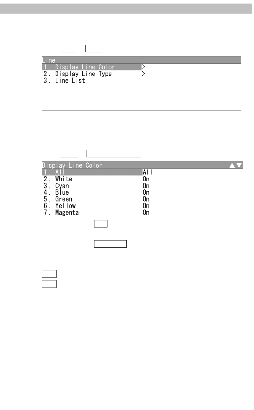
"Line" menu appears.
Display Line Color
Displays the lines with the specified color.
1Open Line - Display Line Color .
When "All" is set to All :
The setting of "All" is prior to individual settings.
When "All" is set to Individual :
Individual settings are prior to the setting of "All".
On : Displays the lines with the specified color.
Off : Does not display the lines with the specified color.
Chapter 2
OPERATIONS
2.17
PLOTTER UNIT
2-141
2
INSTRUCTION MANUAL
Display Line Type
Displays the lines with the specified type.
1Open Line - Display Line Type .
When "All" is set to All :
The setting of "All" is prior to individual settings.
When "All" is set to Individual :
Individual settings are prior to the setting of "All".
On : Displays the lines with the specified type.
Off : Does not display the lines with the specified type.
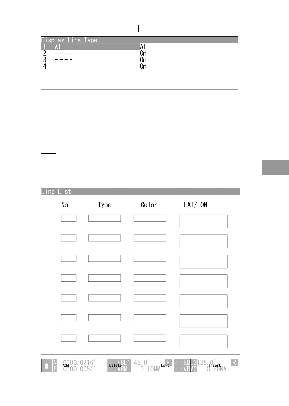
Line List
Displays the line list screen.
Chapter 2
OPERATIONS
2.17
PLOTTER UNIT
2-142
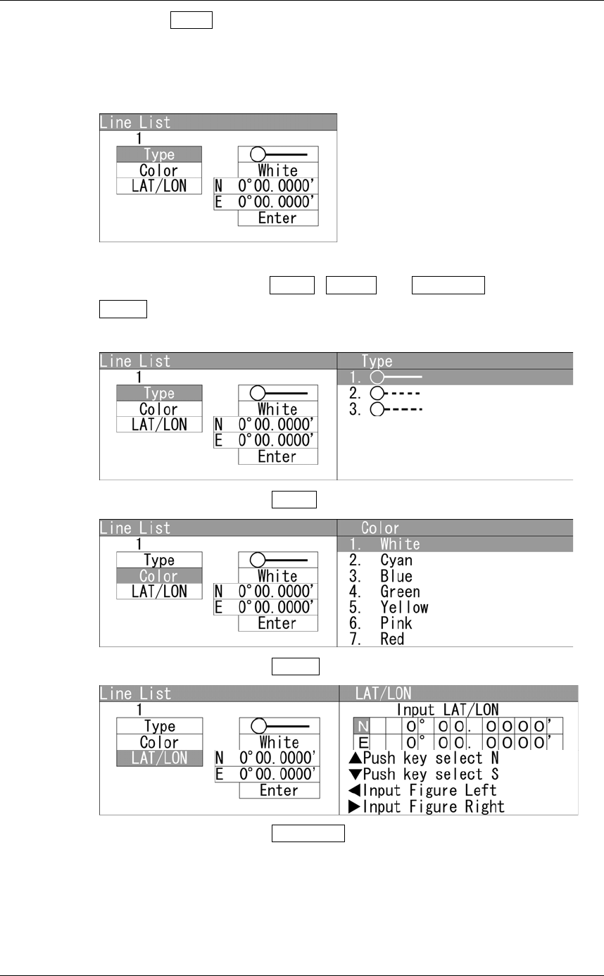
Soft key 1: Add
Creates lines.
Press the soft key 1 "Add".
"Add" menu appears.
Use the cursor keys to input Type , Color and LAT/LON , then press the
Enter .
Use the cursor keys to select the Type .
Use the cursor keys to select the Color .
Use the cursor keys to select the LAT/LON .
Chapter 2
OPERATIONS
2.17
PLOTTER UNIT
2-143
2
INSTRUCTION MANUAL
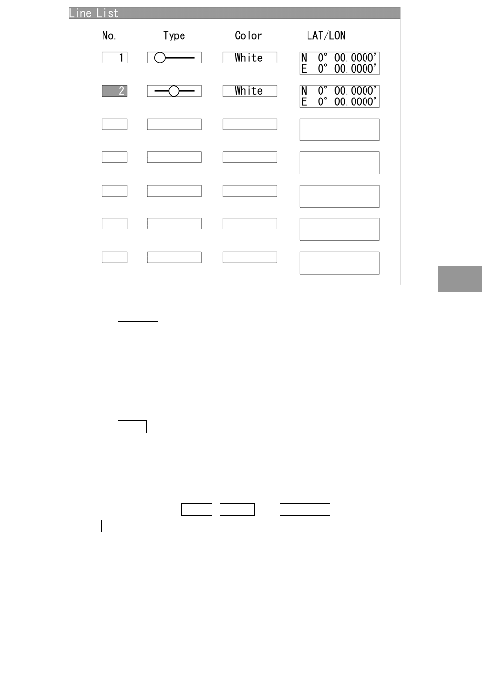
A new line appears in the line list.
Soft key 2: Delete
Erases lines.
Turn the [MULTI] control to select a line list.
Press the soft key 2 "Erase" to erase the mark.
Soft key 3: Edit
Edits lines.
Turn the [MULTI] control to select a line.
Press the soft key 3 "Edit".
Use the cursor keys to edit Type , Color and LAT/LON , then press the
Enter .
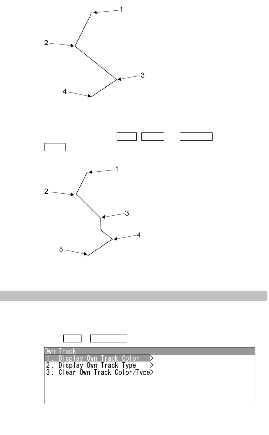
Soft key 4: Insert
Inserts lines.
Chapter 2
OPERATIONS
2.17
PLOTTER UNIT
2-144
Turn the [MULTI] control to select lines 2 to 4. (Line 1 cannot be selected.)
Press the soft key 4 "Insert".
Use the cursor keys to edit Type , Color and LAT/LON , then press the
Enter .
Figure shows the state when line 2 is selected.
2.17.4 DISPLAYING OWN SHIP'S TRACK
Sets the own ship's track display.
"Own Track" operations
1Open Plot - Own Track .
"Own Track" menu appears.
Chapter 2
OPERATIONS
2.17
PLOTTER UNIT
2-145
2
INSTRUCTION MANUAL
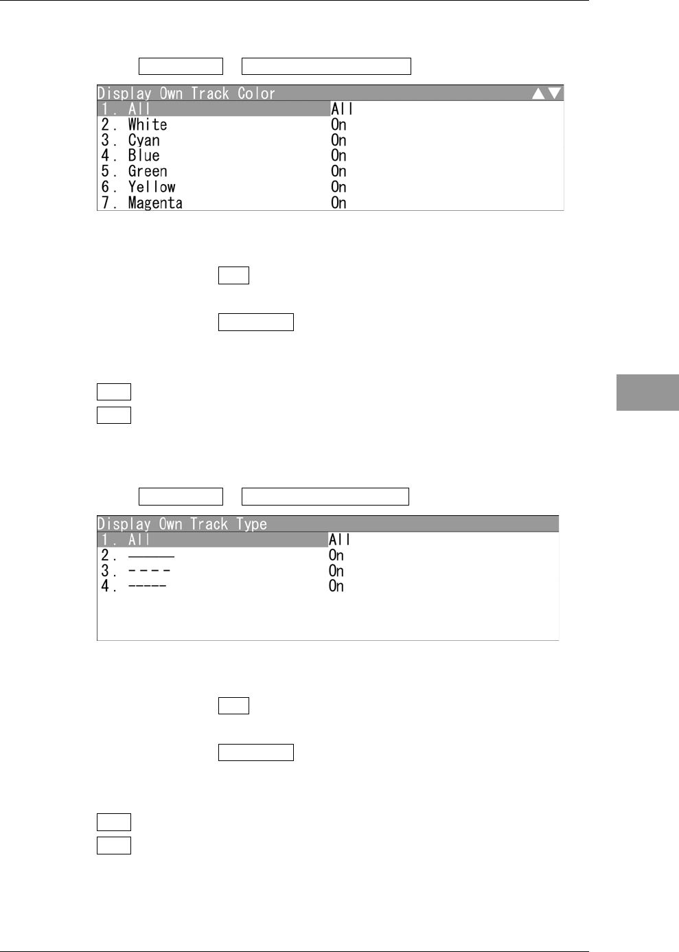
Display Own Track Color
Displays the own tracks with the specified color.
1Open Own Track - Display Own Track Color .
"Display Own Track Color" menu appears.
When "All" is set to All :
The setting of "All" is prior to individual settings.
When "All" is set to Individual :
Individual settings are prior to the setting of "All".
On : Displays the own tracks with the specified color.
Off : Does not display the own tracks with the specified color.
Display Own Track Type
Displays the own tracks with the specified type.
1Open Own Track - Display Own Track Type .
"Display Own Track Type" menu appears.
When "All" is set to All :
The setting of "All" is prior to individual settings.
When "All" is set to Individual :
Individual settings are prior to the setting of "All".
On : Displays the own tracks with the specified type.
Off : Does not display the own tracks with the specified type.
Chapter 2
OPERATIONS
2.17
PLOTTER UNIT
2-146
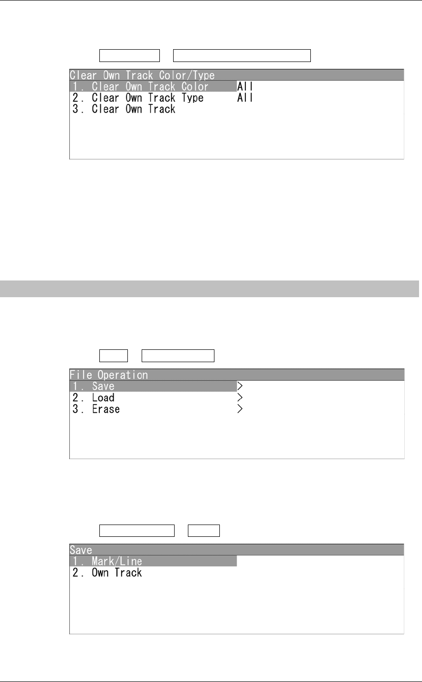
Clear Own Track Color/Type
Sets to clear the own tracks by specifying color/type.
1Open Own Track - Clear Own Track Color/Type .
"Clear Own Track Color/Type" menu appears.
"Clear Own Track Color" : Specifies the color of the own tracks to be cleared.
"Clear Own Track Type" : Specifies the type of the own tracks to be cleared.
"Clear Own Track" : Clears the own tracks according to the setting of "Clear
Own Track Color" and "Clear Own Track Type".
2.17.5 FILE OPERATIONS
Marks, lines and own tracks stored in the equipment can be output via USB terminal.
"File Operation" operations
1Open Plot - File Operation .
"File Operation" menu appears.
Saving Marks/Lines/Own Tracks
Marks, lines and own tracks stored in the equipment can be output via USB terminal.
1Open File Operation - Save .
"Save" menu appears.
Chapter 2
OPERATIONS
2.17
PLOTTER UNIT
2-147
2
INSTRUCTION MANUAL
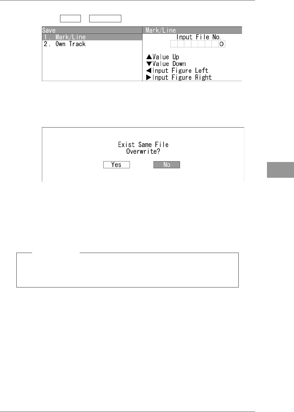
z Saving Mark/Line
1Open Save - Mark/Line .
"Mark/Line" menu appears.
Turn the [MULTI] control to set the file number.
After inputting, "Processing." appears on the radar screen.
After saving is finished, the screen returns to "Save" menu.
When overwriting, the dialog box "Exist Same File. Overwrite?" appears.
When selecting "Yes", "Processing." appears on the radar screen.
After saving is finished, the screen returns to "Erase" menu.
When selecting "No", the screen returns to "Erase" menu.
Note:
z After saving data to a USB memory, move the data to a storage, such as PC,
that can store the data with password to prevent data leakage.
Chapter 2
OPERATIONS
2.17
PLOTTER UNIT
2-148
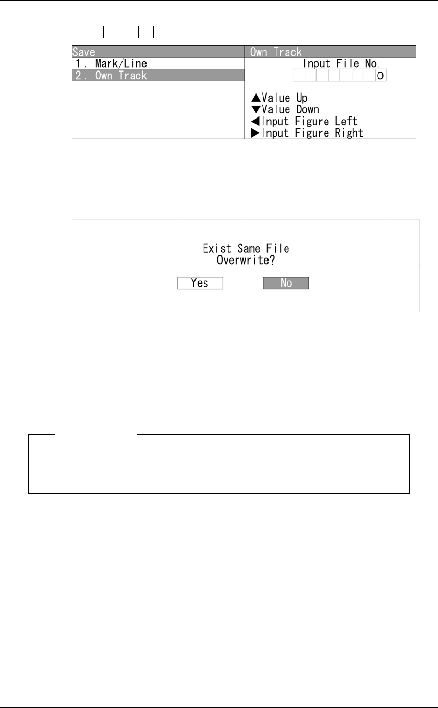
z Saving Own Track
1Open Save - Own Track .
"Own Track" menu appears.
Turn the [MULTI] control to set the file number.
After inputting, "Processing." appears on the radar screen.
After saving is finished, the screen returns to "Save" menu.
When overwriting, the dialog box "Exist Same File. Overwrite?" appears.
When selecting "Yes", "Processing." appears on the radar screen.
After saving is finished, the screen returns to "Erase" menu.
When selecting "No", the screen returns to "Erase" menu.
Note:
z After saving data to a USB memory, move the data to a storage, such as PC,
that can store the data with password to prevent data leakage.
Chapter 2
OPERATIONS
2.17
PLOTTER UNIT
2-149
2
INSTRUCTION MANUAL
Loading Marks/Lines/Own Tracks
Loads marks, lines and own tracks from USB.
1Open File Operation - Load .
"Load" menu appears.
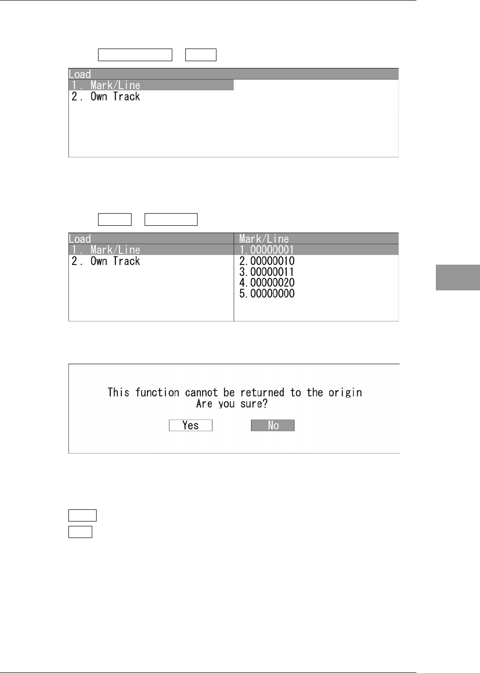
z Loading Mark/Line
1Open Load - Mark/Line .
"Mark/Line" menu appears.
Turn the [MULTI] control to select the file number.
When selecting the file, the dialog box "This function cannot be returned to the
origin. Are you sure?" appears.
Yes : Loads data via USB.
No : Does not load data via USB.
When selecting "Yes", "Processing." appears on the radar screen.
After saving is finished, the screen returns to "Erase" menu.
When selecting "No", the screen returns to "Erase" menu.
Chapter 2
OPERATIONS
2.17
PLOTTER UNIT
2-150
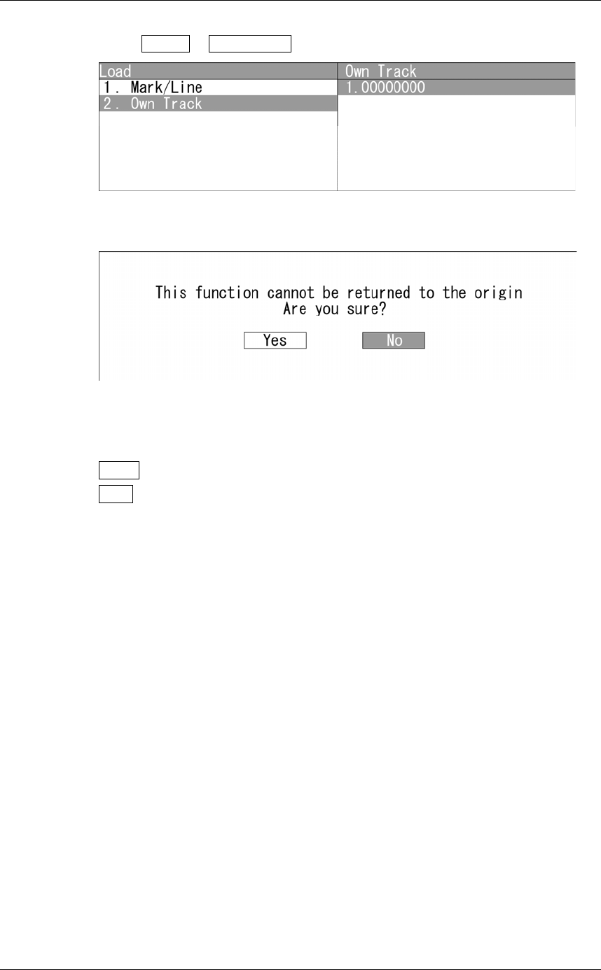
z Loading Own Track
1Open Load - Own Track .
"Own Track" menu appears.
Turn the [MULTI] control to select the file number.
When selecting the file, the dialog box "This function cannot be returned to the
origin. Are you sure?" appears.
Yes : Loads data via USB.
No : Does not load data via USB.
When selecting "Yes", "Processing." appears on the radar screen.
After saving is finished, the screen returns to "Erase" menu.
When selecting "No", the screen returns to "Erase" menu.
Chapter 2
OPERATIONS
2.17
PLOTTER UNIT
2-151
2
INSTRUCTION MANUAL
Erasing Marks/Lines/Own Tracks
Erases marks, lines and own tracks via USB.
1Open File Operation - Erase .
"Erase" menu appears.
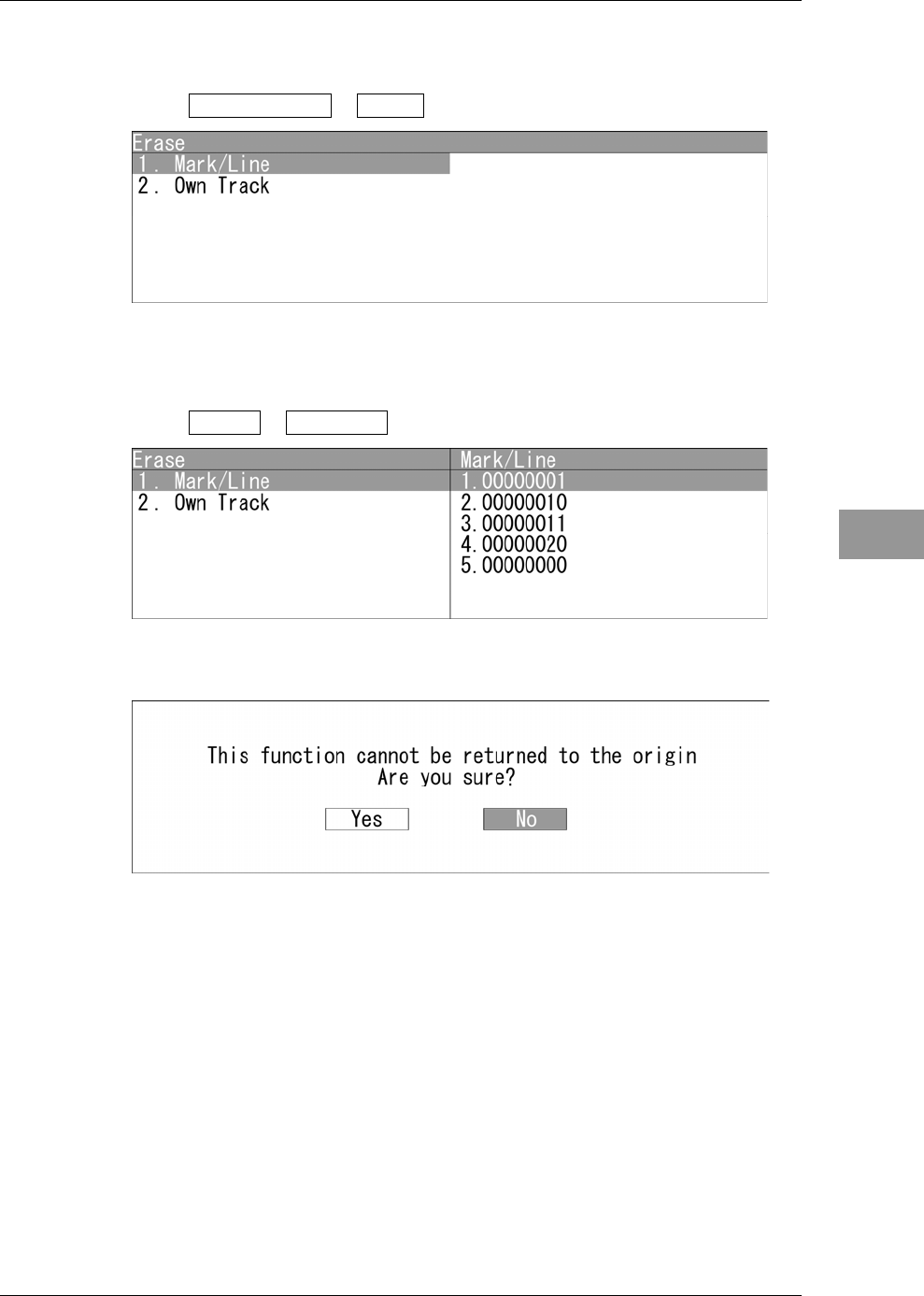
z Erasing Mark/Line
1Open Erase - Mark/Line .
"Mark/Line" menu appears.
Turn the [MULTI] control to select the file number.
When selecting the file, the dialog box "This function cannot be returned to the
origin. Are you sure?" appears.
When selecting "Yes", "Processing." appears on the radar screen.
After saving is finished, the screen returns to "Erase" menu.
When selecting "No", the screen returns to "Erase" menu.
Chapter 2
OPERATIONS
2.17
PLOTTER UNIT
2-152
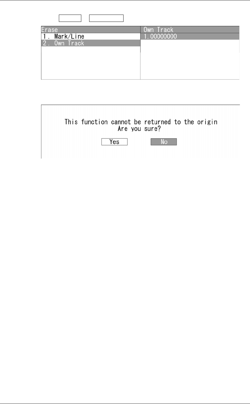
z Erasing Own Track
1Open Erase - Own Track .
"Own Track" menu appears.
Turn the [MULTI] control to set the file number.
When selecting the file, the dialog box "This function cannot be returned to the
origin. Are you sure?" appears.
When selecting "Yes", "Processing." appears on the radar screen.
After saving is finished, the screen returns to "Erase" menu.
When selecting "No", the screen returns to "Erase" menu.
Chapter 2
OPERATIONS
2.18
SETTING TIMED TX
2-153
2
INSTRUCTION MANUAL
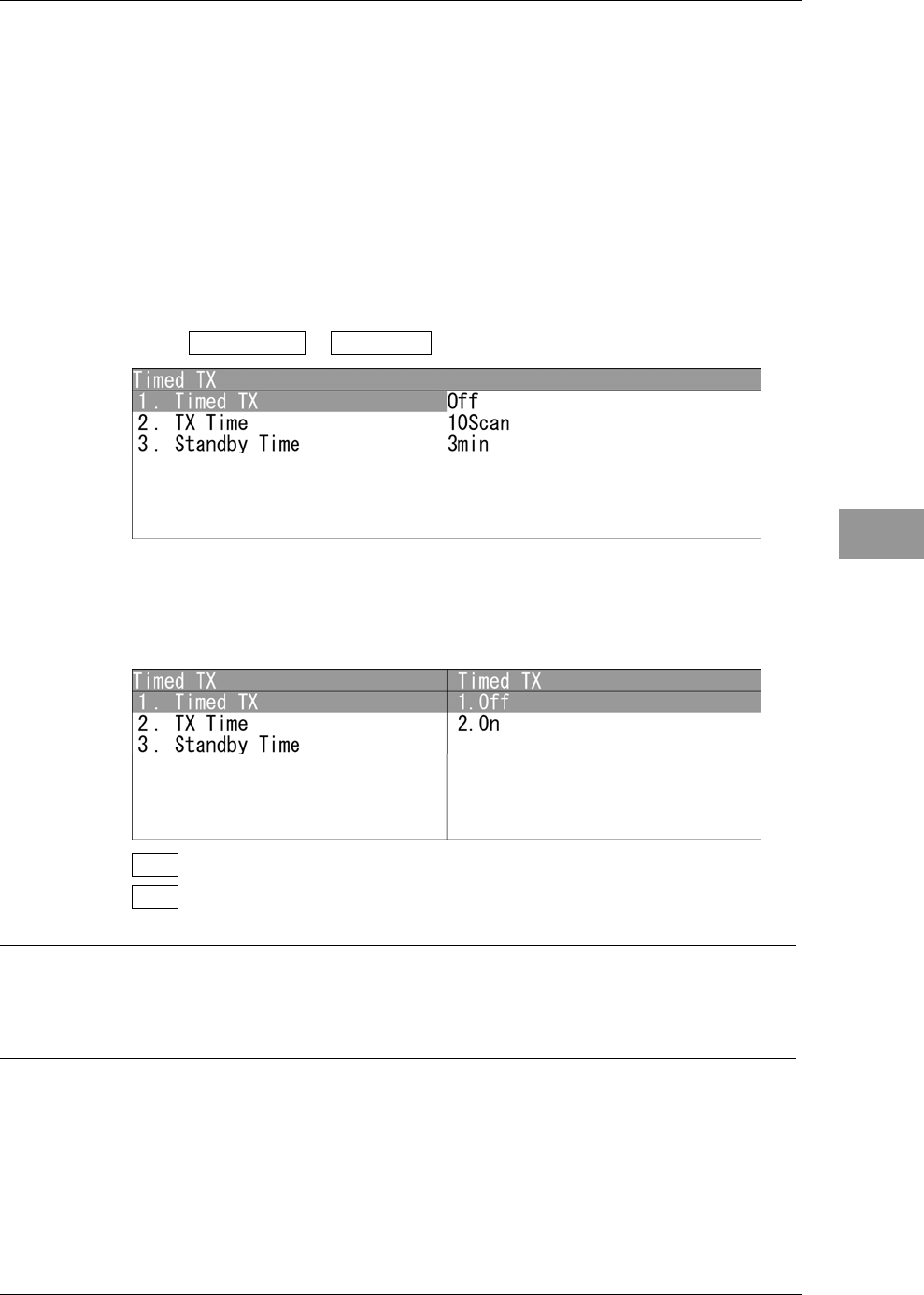
2.18 SETTING TIMED TX
Sets timed TX function.
Timed TX
This function reduces power consumption.
When using timed TX function, the operation state is repeatedly changed between TX
and standby state.
The timed TX function can set TX time and standby time as desired.
"Timed TX" operations
1Open Main Menu - Timed TX .
"Timed TX" menu appears.
Turning on/off Timed TX Function
Turns on/off the timed TX function.
Off : Sets the timed TX function to Off.
On : Sets the timed TX function to On.
Reference:
The timed TX function can be turned off only in TX state. It cannot be turned off in standby
state.
Chapter 2
OPERATIONS
2.18
SETTING TIMED TX
2-154
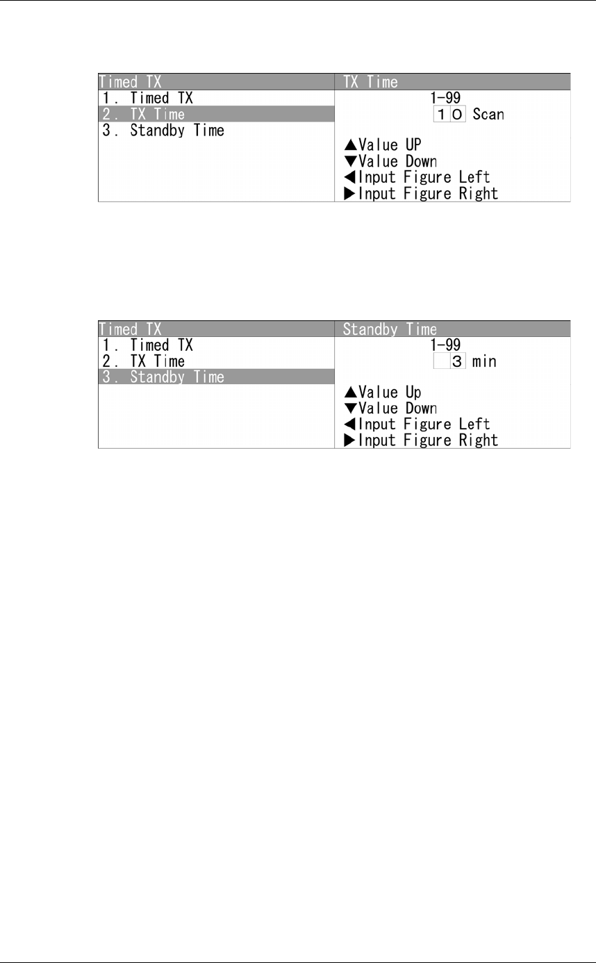
Setting TX Time
Sets the number of antenna rotation.
Turn the [MULTI] control to set the TX time.
TX time can be adjusted between 0 and 99Scan.
Setting Standby Time
Sets the time for standby state.
Turn the [MULTI] control to set the Standby Time.
The standby time can be adjusted between 0 and 99min.