Japan Radio NKE2063 MARINE RADAR User Manual NKE2063UserMan
Japan Radio Co Ltd. MARINE RADAR NKE2063UserMan
UserManual.wiki
>
Japan Radio
>
NKE2063 User Manual
>
Users Manual 3
Contents
1.
Users Manual 1
2.
Users Manual 2
3.
Users Manual 3
4.
Users Manual 4
Users Manual 3
Navigation menu
Upload a User Manual
Namespaces
Wiki Guide
HTML
PDF
Info
Views
User Manual
Discussion / Help
Navigation
![Chapter 2OPERATIONS2.8BASIC MENU OPERATIONS 2-772INSTRUCTION MANUAL 4Press the cursor key (down) or turn the [MULTI] control (clockwise) to select IR . 5Press the [ENT] key, the cursor key (right) or the [MULTI] control. "IR" menu appears. Selectable items are displayed on the right pane of the menu. "IR" is color-inverted.The current setting is color-inverted.](https://usermanual.wiki/Japan-Radio/NKE2063.Users-Manual-3/User-Guide-1644966-Page-1.png)
![Chapter 2OPERATIONS2.8BASIC MENU OPERATIONS 2-786Select the desired item, then press the [ENT] key or the [MULTI] control. 7The setting is determined and displayed. z Closing the menu Repeatedly press the [CLEAR] key or the cursor key (left) to return to the upper level and then close the menu screen. Select the desired item. Setting is determined.](https://usermanual.wiki/Japan-Radio/NKE2063.Users-Manual-3/User-Guide-1644966-Page-2.png)
![Chapter 2OPERATIONS2.9RADAR ECHO SETTINGS 2-80When a high interference rejection level is selected, the radar's ability of detecting small targets such as buoys and small boats lowers. In general, Low should be selected. 2.9.2 SETTING FOR ENHANCING TARGETS Setting for Enhancing Targets The dimension of video display is enlarged in angle and distance. Note: z When target enhancement function is used, echo displays of two targets closing in angle and distance may be displayed in PPI screen as one target. 1Open RADAR Echo - Target Enhance . "Target Enhance" menu appears. Off : Select this mode particularly when resolution is required. Level1 : Select this mode in general. Expands the radar echo area at 1 step for vertical direction and at 1 step for horizontal direction. Level2 : Select this mode to easily view the radar video. Expands the radar echo area at 1 step for vertical direction and at 2 steps for horizontal direction. Level3 : Select this mode to detect small targets such as buoys. Expands the radar echo area at 2 steps for vertical direction and at 3 steps for horizontal direction. Reference:When Level3 is selected, sea clutter returns and rain/snow clutter returns are apt to be enhanced. When using this enhance mode, operate the [SEA] control and the [RAIN] control to suppress sea clutter returns and rain/snow clutter returns. In general, Level1 or Level2 should be selected. ](https://usermanual.wiki/Japan-Radio/NKE2063.Users-Manual-3/User-Guide-1644966-Page-4.png)

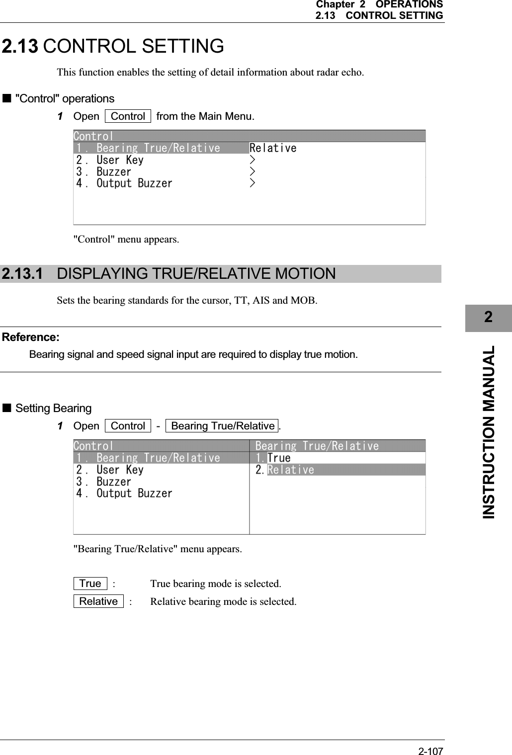
![Chapter 2OPERATIONS2.13CONTROL SETTING 2-1092INSTRUCTION MANUAL Using user keys Operates as user keys. z Displaying the menu assigned to the user key1 Hold down the [GAIN] control. z Displaying the menu assigned to the user key2 Hold down the [SEA] control. z Displaying the menu assigned to the user key3 Hold down the [RAIN] control.](https://usermanual.wiki/Japan-Radio/NKE2063.Users-Manual-3/User-Guide-1644966-Page-33.png)
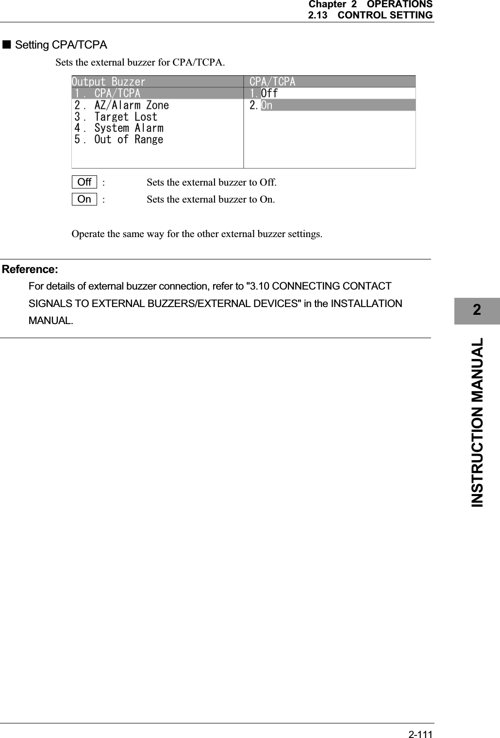
![Chapter 2OPERATIONS2.13CONTROL SETTING 2-1102.13.3 ADJUSTING BUZZER VOLUME When an alarm goes off, the operation panel of the equipment produces a sound to notify users of state changes. Adjust the sound volume as follows. "Buzzer" operations 1Open Control - Buzzer . "Buzzer" menu appears. Setting volume Sets Key ACK volume. Turn the [MULTI] control to adjust Key ACK volume. Key ACK volume can be adjusted between 0 and 255. When "0" is set, the volume is turned off. Operate the same way for the other volume settings. "Output Buzzer" operations 1Open Control - Output Buzzer . "Output Buzzer" menu appears.](https://usermanual.wiki/Japan-Radio/NKE2063.Users-Manual-3/User-Guide-1644966-Page-34.png)
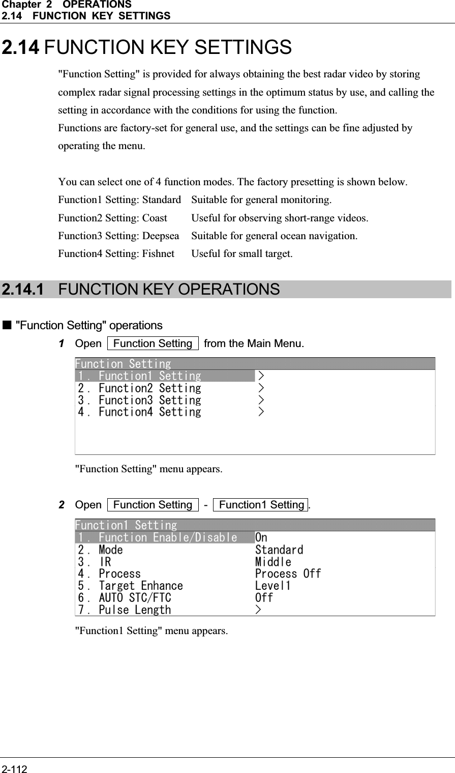
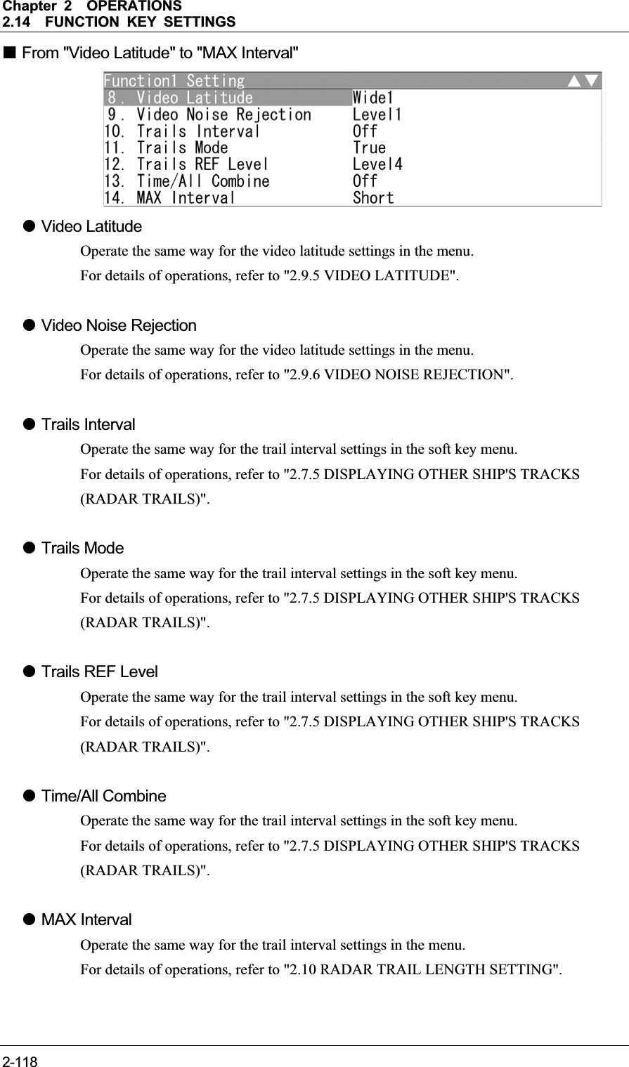
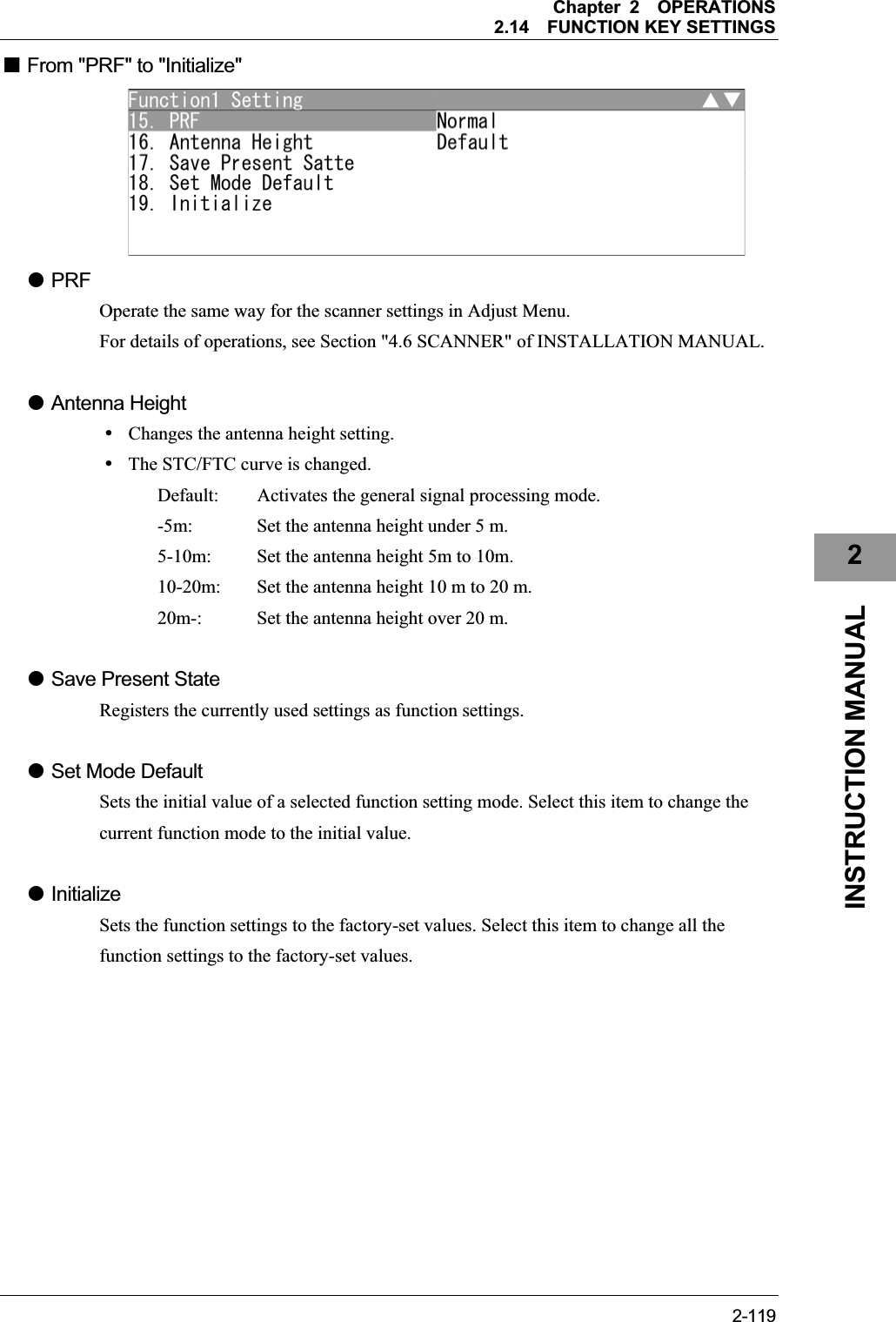
![Chapter 2OPERATIONS2.14FUNCTION KEY SETTINGS 2-1132INSTRUCTION MANUAL Calling functions 1Press the [FUNC] key. Each time you press the [FUNC] key, the setting is cyclically changed in order of: Function off Function1 Setting Function2 Setting Function3 Setting Function4 Setting Function off The currently called function mode is indicated as the right of the screen. z Calling function setting menu 1Hold down the [FUNC] key. "Function Setting" menu appears when holding down the [FUNC] key. Changing the setting z Temporarily changing the setting yWhen radar signal processing setting is changed by using the soft key or the menu operation while function 1 to 4 is called, the change is temporarily reflected to the operating state. ySince this method does not change the memory contents, the new setting is deleted as soon as another function is called. yWhen the previous function is called again, operation is performed according to the memory contents. z Changing memory contents yTo change the memory contents of functions 1 to 4, use [Function Setting] in the Main Menu.](https://usermanual.wiki/Japan-Radio/NKE2063.Users-Manual-3/User-Guide-1644966-Page-37.png)
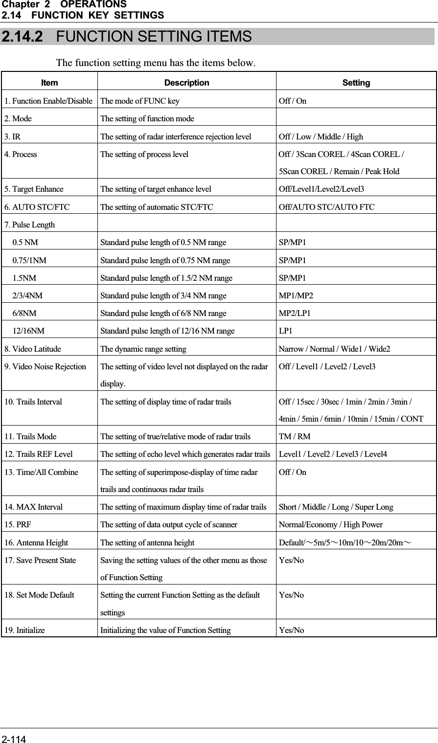
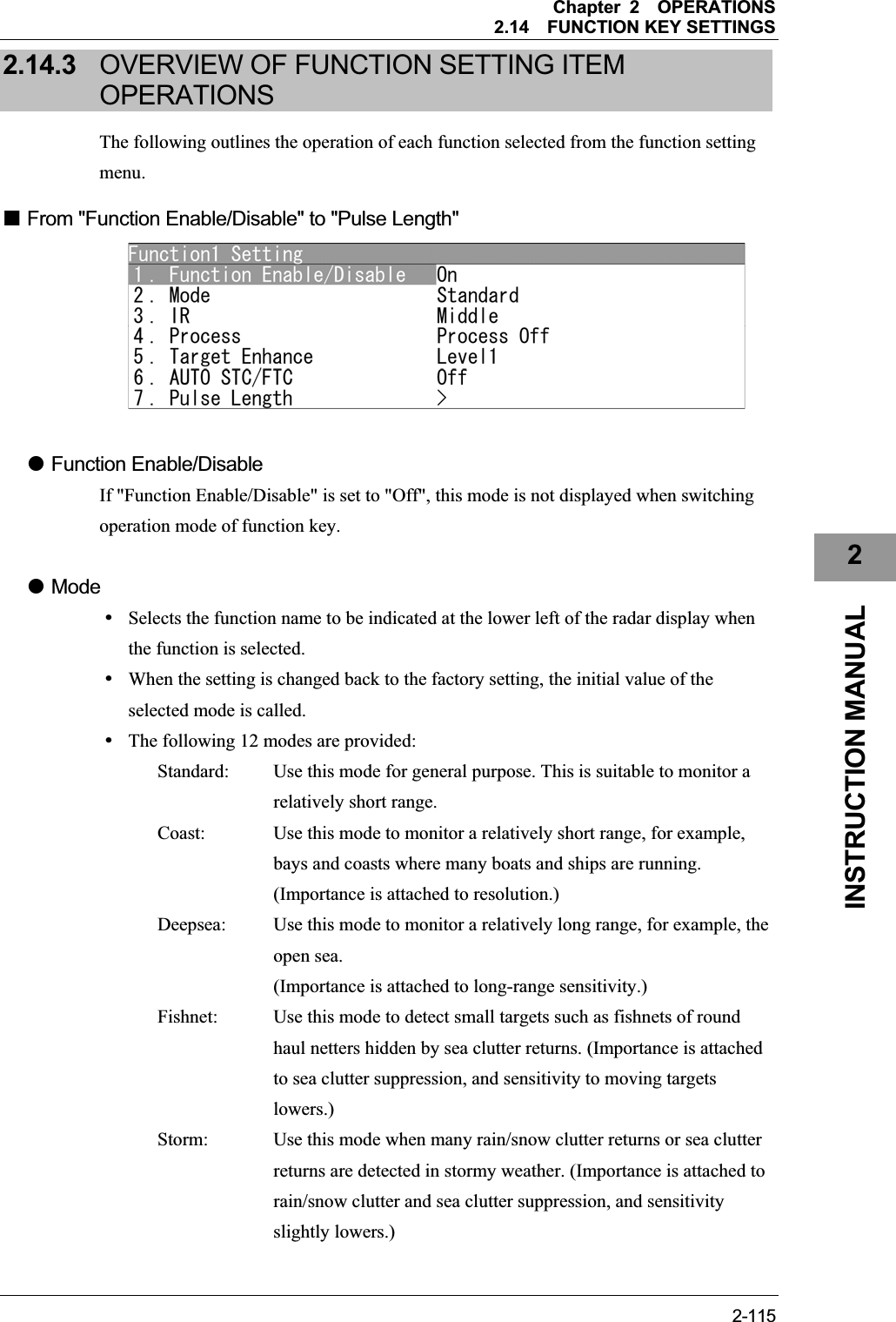
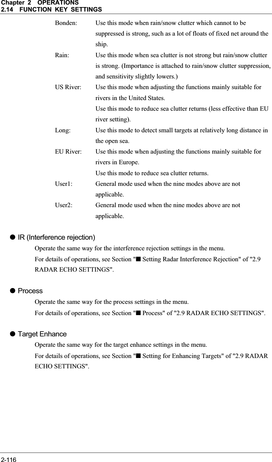
![Chapter 2OPERATIONS2.14FUNCTION KEY SETTINGS 2-1172INSTRUCTION MANUAL z AUTO STC/FTC (Automatic clutter suppression) yDetects unwanted waves such as rain/snow clutter and sea clutter and automatically suppresses them. yWhen the sea state or weather changes, this function automatically performs suppression processing in accordance with the situation. ySuppression processing is not full automatic, and requires the operator to control the afterimages of unwanted waves. yTo control the afterimage of sea clutter, use the [SEA] control. yTo control the afterimage of rain/snow clutter, use the [RAIN] control. yIn areas where the density of unwanted waves is low, unwanted waves may remain being judged as targets. Thus, use the automatic clutter suppression mode together with the video process mode. yCharacteristics of the automatic clutter suppression function: Off: Disables the automatic clutter suppression function. Select "Off" when rain/snow clutter and sea clutter are not strong or when the ship is in a bay. AUTO STC: Automatically detects the strength of sea clutter, and performs the most suitable sea clutter suppression processing. Even when the strength of sea clutter varies depending on the wind direction, AUTO STC performs the most suitable suppression processing.Land like islands can be displayed naturally. Since rain clouds outside sea clutter areas are recognized as land, there is no effect of suppressing rain/snow clutter. Use the [RAIN] control to set the rain/snow clutter suppression function.AUTO FTC: Along with AUTO STC, this function automatically detects the strength of rain/snow clutter, and performs the most suitable rain/snow clutter suppression processing. Since land is recognized as rain clouds, land videos become obscure.z Pulse Length ySets the standard transmitter pulse length in each range. yWhen the range is called, the pulse length is used.](https://usermanual.wiki/Japan-Radio/NKE2063.Users-Manual-3/User-Guide-1644966-Page-41.png)
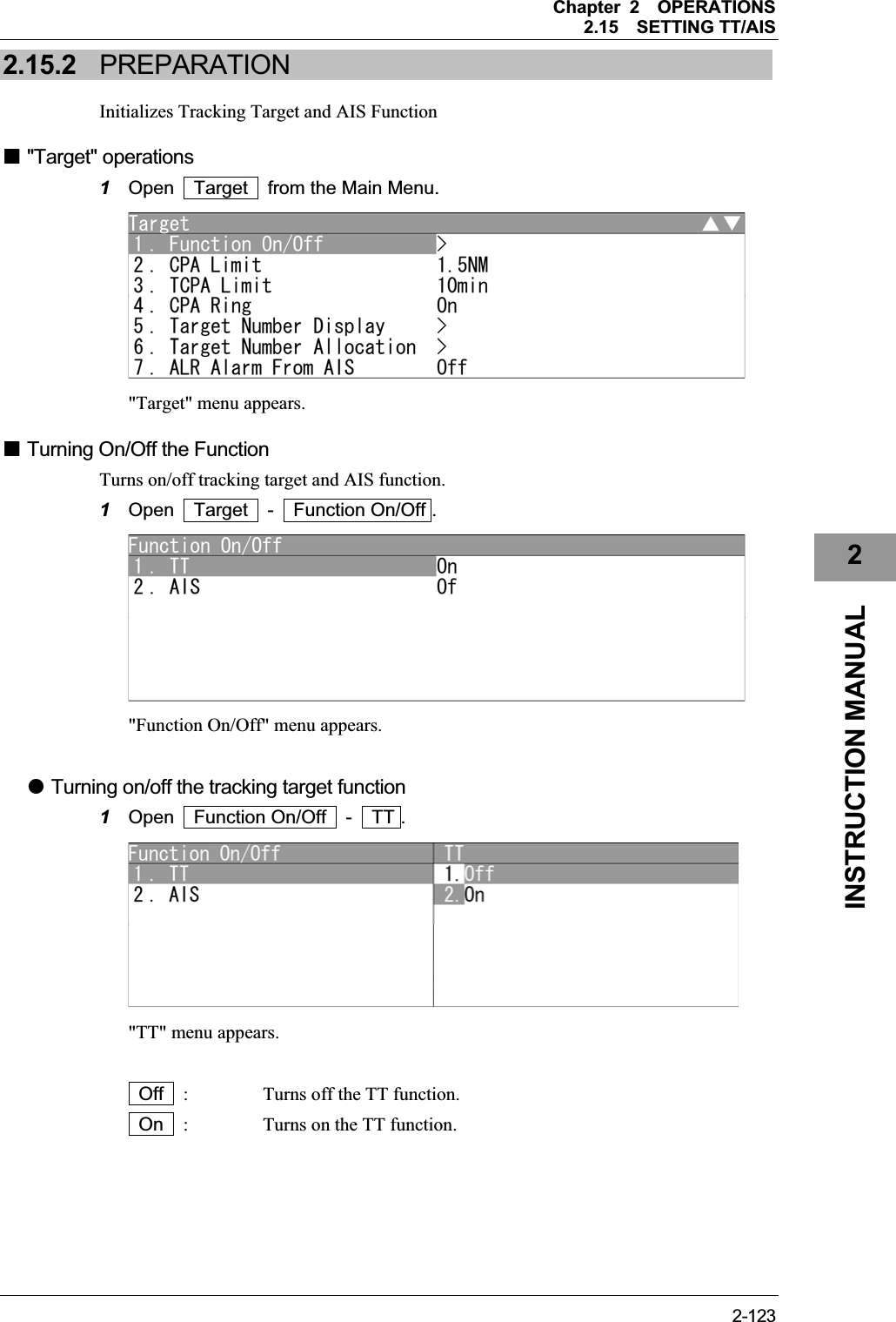
![Chapter 2OPERATIONS2.15SETTING TT/AIS 2-124z Turning on/off the AIS function 1Open Function On/Off - AIS . "AIS" menu appears. Off : Turns off the AIS function. On : Turns on the AIS function. Setting Collision Decision Criteria Set and check collision decision criteria before operating. Input the CPA Limit value. Turn the [MULTI] control to set the CPA Limit value. The CPA Limit value can be set between 0.1 and 9.9 NM. Input the TCPA Limit value. Turn the [MULTI] control to set the TCPA Limit value. The TCPA Limit value can be set between 1 and 99 min.](https://usermanual.wiki/Japan-Radio/NKE2063.Users-Manual-3/User-Guide-1644966-Page-48.png)
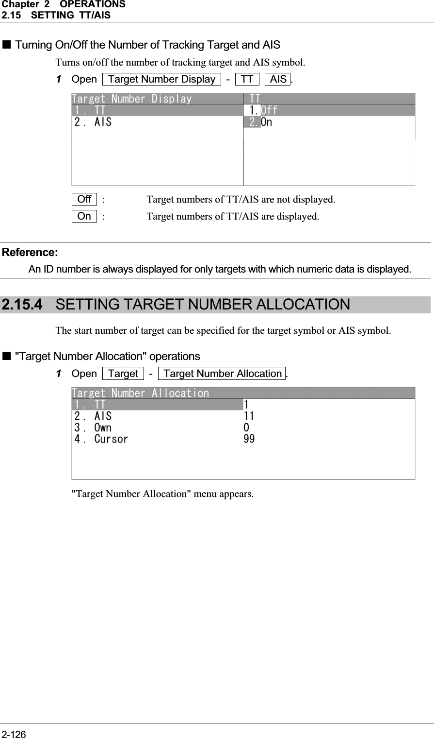
![Chapter 2OPERATIONS2.15SETTING TT/AIS 2-1272INSTRUCTION MANUAL Target Number Allocation Turns on/off the start number of target for tracking. 1Open Target Number Allocation - TT AIS Own Ship's Cursor . Turn the [MULTI] control to set the start number of target. Operate the same way for the other target numbers. TT : The start number of target can be adjusted between 0 and 90. AIS : The start number of target can be adjusted between 0 and 50. Own Ship's : The start number of target can be adjusted between 0 and 99. Cursor : The start number of target can be adjusted between 0 and 99. Reference:Set the target number of TT/AIS not to overlap each other. 2.15.5 SETTING AIS ALARM Sets the display of NMEA ALR sentence received from AIS. Setting AIS Alarm 1Open Target - ALR Alarm From AIS . Off : ALR alarm is turned off. On : ALR alarm is turned on.](https://usermanual.wiki/Japan-Radio/NKE2063.Users-Manual-3/User-Guide-1644966-Page-51.png)
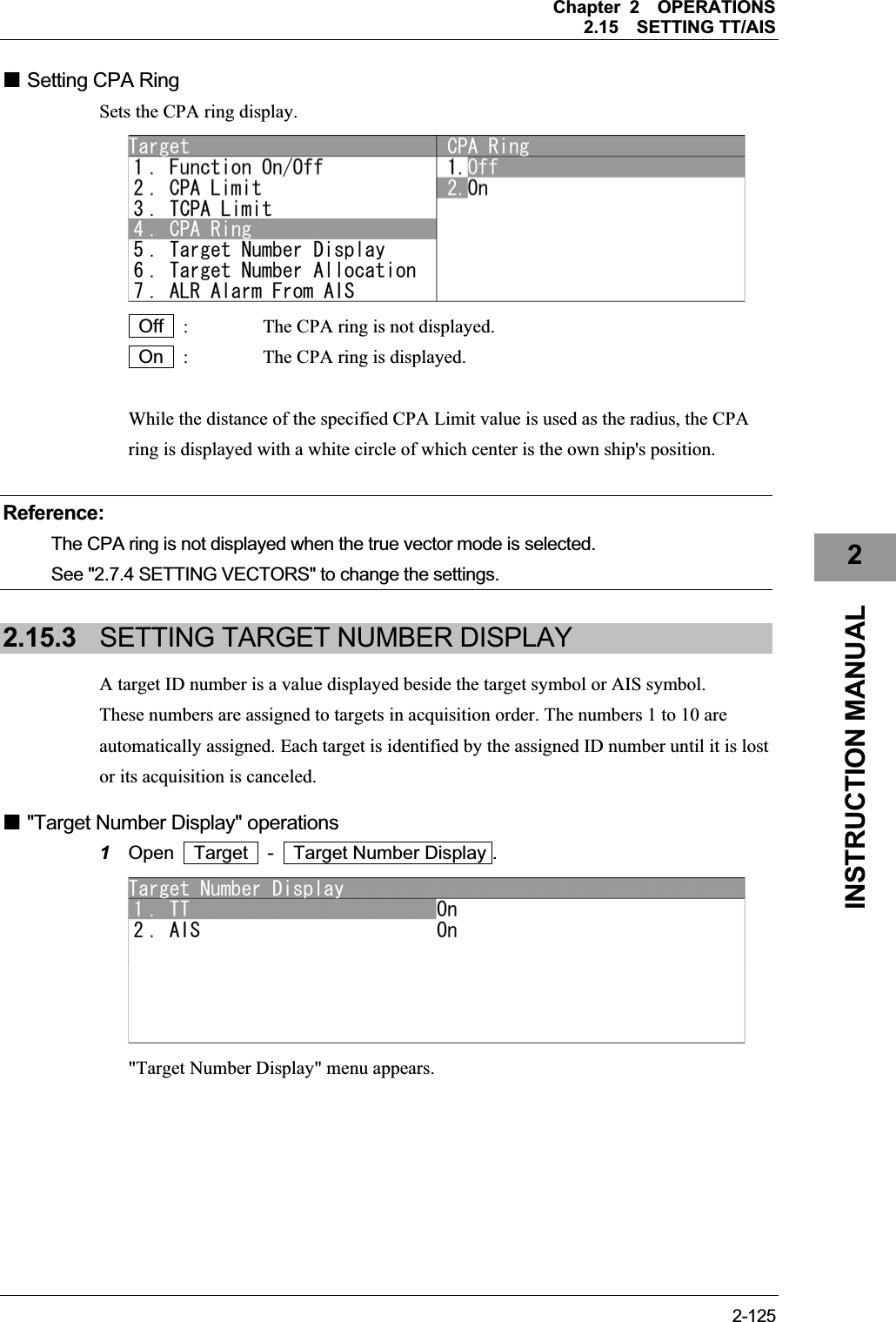
![Chapter 2OPERATIONS2.15SETTING TT/AIS 2-1282.15.6 SETTING AIS DISPLAY TARGET Set the number of AIS display targets. Set this to get a better look at the screen by limiting the number of AIS symbols. Setting AIS Display Target 1Open Target - AIS Display Target . 20 : The number of AIS display targets is set to 20. 30 : The number of AIS display targets is set to 30. 40 : The number of AIS display targets is set to 40. 50 : The number of AIS display targets is set to 50. 2.15.7 SETTING AIS DESTINATION SHIP (DirecTrakTM)AIS destination ship is the function to display the user-specified ship as the destination. If MMSI of AIS target is set, the destination ship can be specified. Setting AIS Destination Ship 1Open Target - AIS Destination Ship . Turn the [MULTI] control to set MMSI. MMSI can be adjusted between 0 and 999999999.](https://usermanual.wiki/Japan-Radio/NKE2063.Users-Manual-3/User-Guide-1644966-Page-52.png)
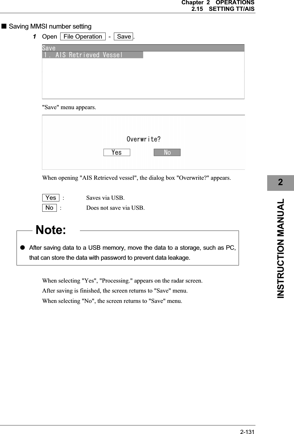
![Chapter 2OPERATIONS2.15SETTING TT/AIS 2-1292INSTRUCTION MANUAL 2.15.8 SETTING AIS RETRIEVED VESSEL AIS retrieved vessel is the function to preferentially display the user-specified ship. If MMSI of AIS target is set, the retrieved vessel can be specified. Reference:AIS retrieved vessel can be set up to 10 vessels. "AIS Retrieved vessel" operations 1Open Target - AIS Retrieved Vessel . "AIS Retrieved Vessel" menu appears. MMSI Number Setting 1Open AIS Retrieved Vessel - MMSI Number Setting - Retrieved Vessel info #1 . Turn the [MULTI] control to set MMSI number. MMSI number can be adjusted between 0 and 999999999. Operate the same way for the other retrieved vessels.](https://usermanual.wiki/Japan-Radio/NKE2063.Users-Manual-3/User-Guide-1644966-Page-53.png)
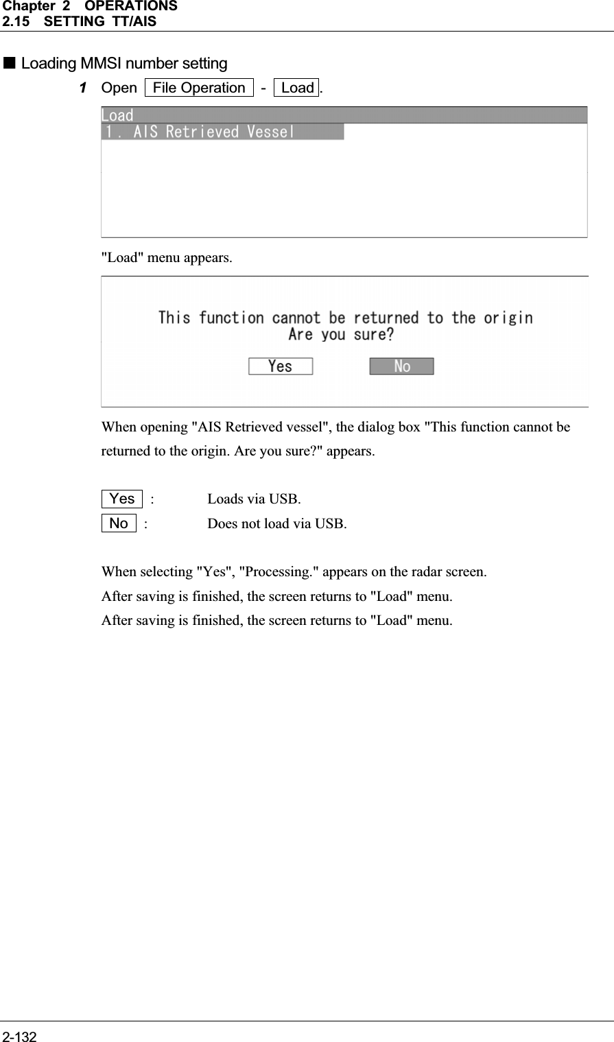
![Chapter 2OPERATIONS2.15SETTING TT/AIS 2-1302.15.9 SETTING AIS FILTER Sets the range for AIS filter. Reference:For details of AIS filter, refer to "2.7.22 SETTING AIS FILTER". Setting AIS Filter 1Open Target - AIS Filter . Turn the [MULTI] control to set the range for AIS filter. The range can be set between 0 and 72.0 NM. 2.15.10 FILE OPERATION The stored MMSI number setting of AIS retrieved vessel is output via USB. File Operation 1Open Target - File Operation . "File Operation" menu appears.](https://usermanual.wiki/Japan-Radio/NKE2063.Users-Manual-3/User-Guide-1644966-Page-54.png)
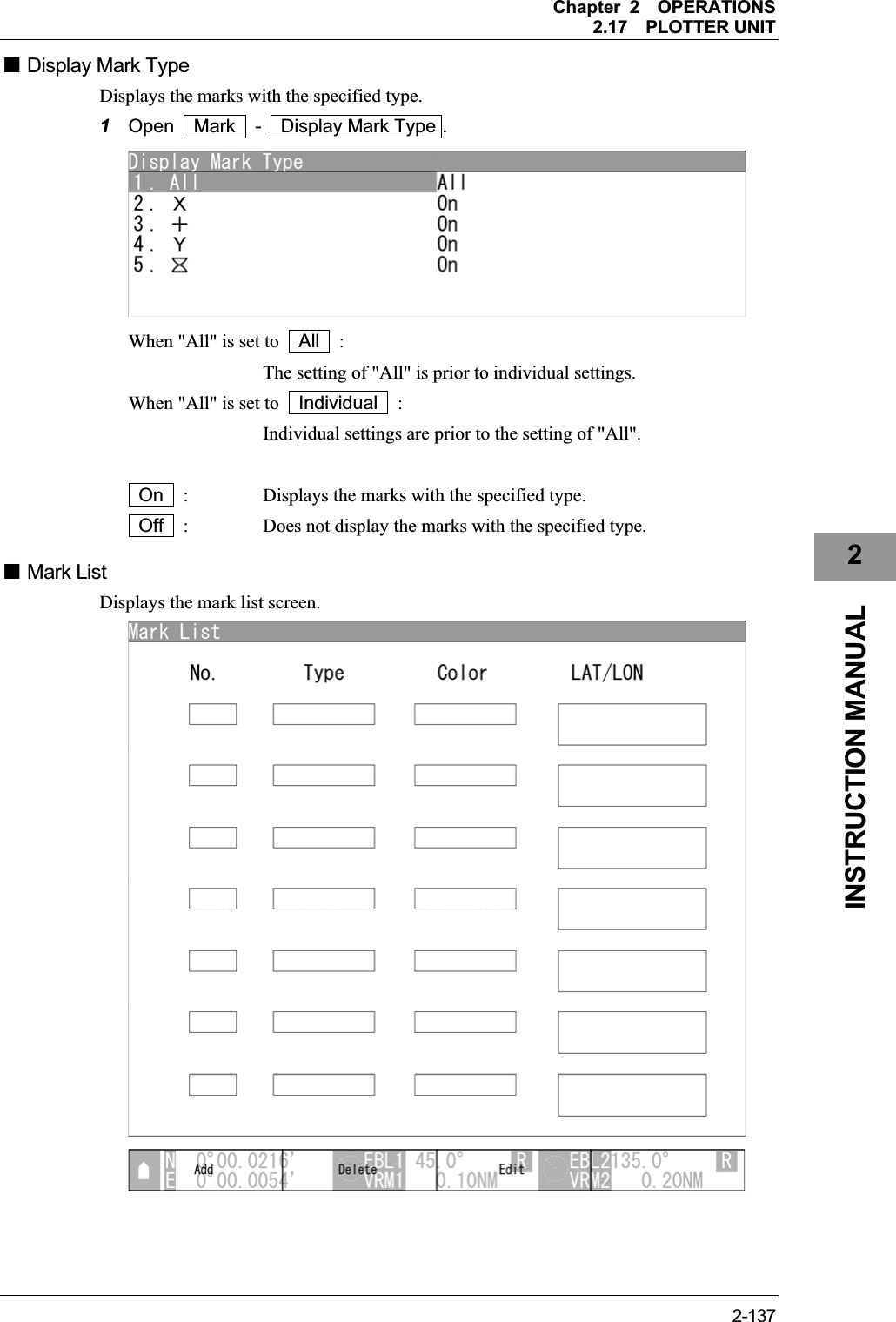
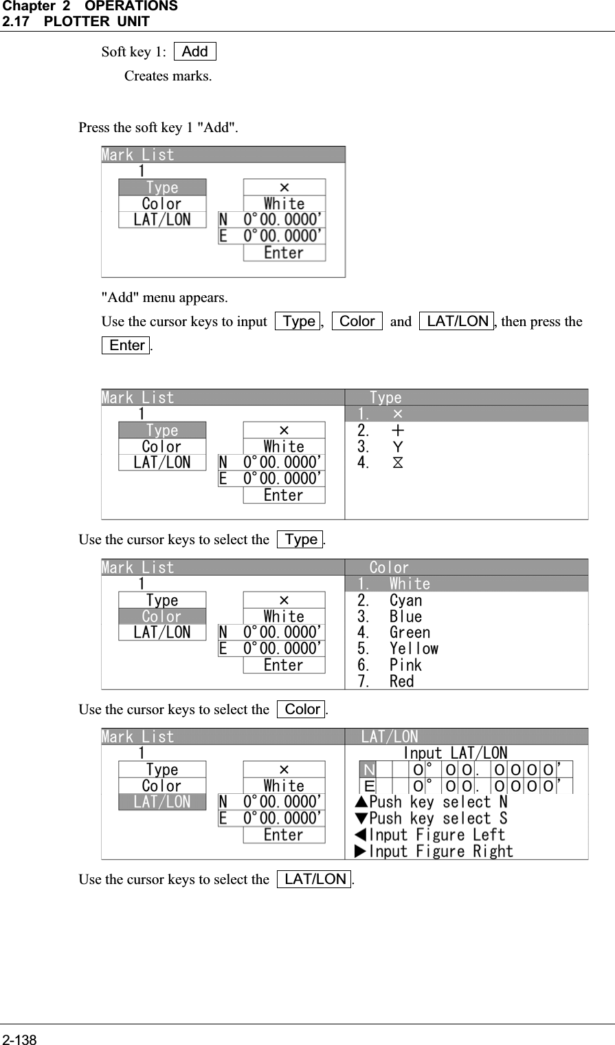
![Chapter 2OPERATIONS2.17PLOTTER UNIT 2-1392INSTRUCTION MANUAL A new mark appears in the mark list. Soft key 2: Delete Erases marks. Turn the [MULTI] control to select a mark list. Press the soft key 2 "Erase" to erase the mark. Soft key 3: Edit Edits marks. Turn the [MULTI] control to select a mark. Press the soft key 3 "Edit". Use the cursor keys to edit Type , Color and LAT/LON , then press the Enter .](https://usermanual.wiki/Japan-Radio/NKE2063.Users-Manual-3/User-Guide-1644966-Page-63.png)
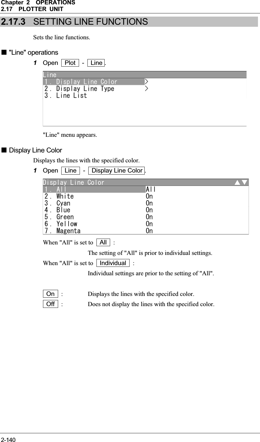
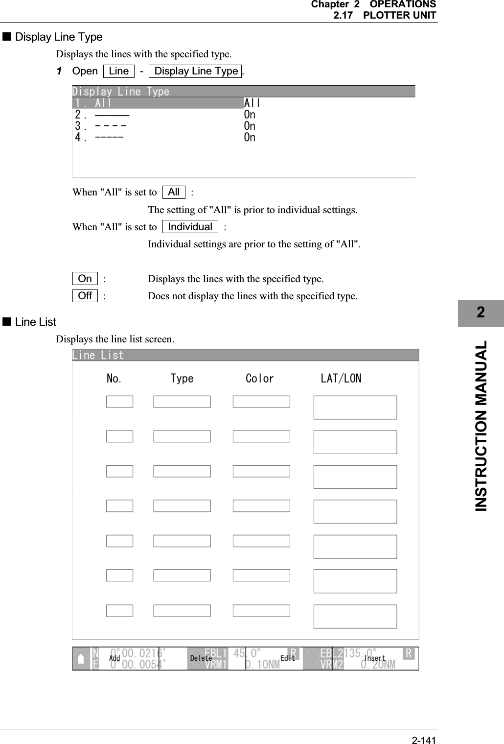
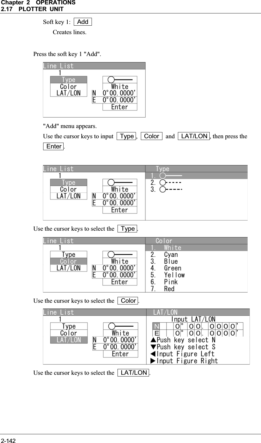
![Chapter 2OPERATIONS2.17PLOTTER UNIT 2-1432INSTRUCTION MANUAL A new line appears in the line list. Soft key 2: Delete Erases lines. Turn the [MULTI] control to select a line list. Press the soft key 2 "Erase" to erase the mark. Soft key 3: Edit Edits lines. Turn the [MULTI] control to select a line. Press the soft key 3 "Edit". Use the cursor keys to edit Type , Color and LAT/LON , then press the Enter .Soft key 4: Insert Inserts lines.](https://usermanual.wiki/Japan-Radio/NKE2063.Users-Manual-3/User-Guide-1644966-Page-67.png)
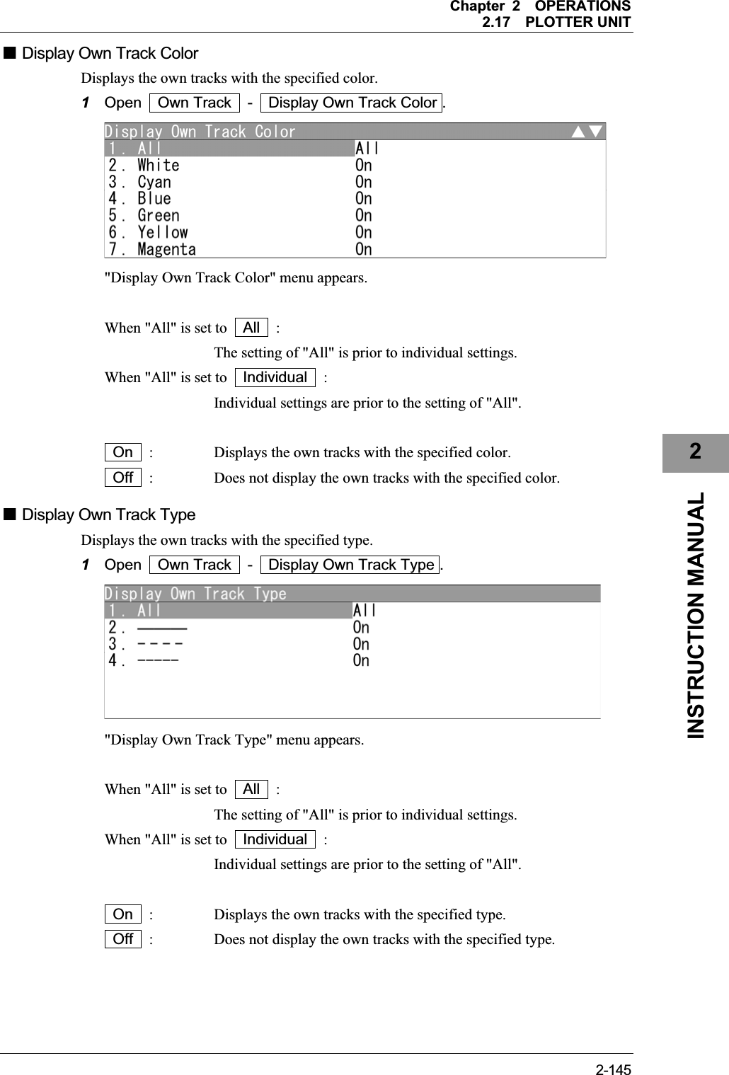
![Chapter 2OPERATIONS2.17PLOTTER UNIT 2-144Turn the [MULTI] control to select lines 2 to 4. (Line 1 cannot be selected.) Press the soft key 4 "Insert". Use the cursor keys to edit Type , Color and LAT/LON , then press the Enter .Figure shows the state when line 2 is selected. 2.17.4 DISPLAYING OWN SHIP'S TRACK Sets the own ship's track display. "Own Track" operations 1Open Plot - Own Track . "Own Track" menu appears.](https://usermanual.wiki/Japan-Radio/NKE2063.Users-Manual-3/User-Guide-1644966-Page-68.png)
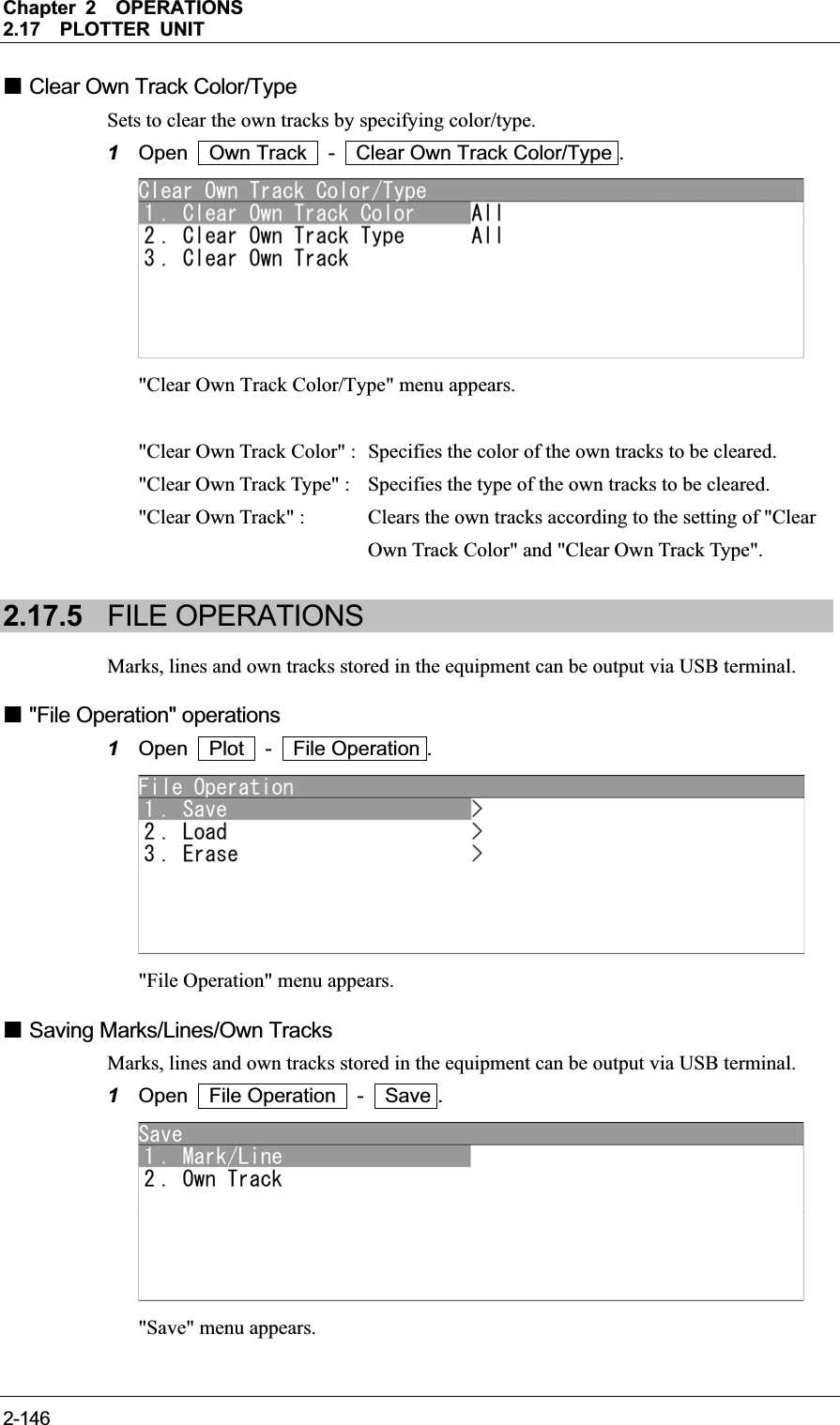
![Chapter 2OPERATIONS2.17PLOTTER UNIT 2-1472INSTRUCTION MANUAL z Saving Mark/Line 1Open Save - Mark/Line . "Mark/Line" menu appears. Turn the [MULTI] control to set the file number. After inputting, "Processing." appears on the radar screen. After saving is finished, the screen returns to "Save" menu. When overwriting, the dialog box "Exist Same File. Overwrite?" appears. When selecting "Yes", "Processing." appears on the radar screen. After saving is finished, the screen returns to "Erase" menu. When selecting "No", the screen returns to "Erase" menu. Note: z After saving data to a USB memory, move the data to a storage, such as PC, that can store the data with password to prevent data leakage.](https://usermanual.wiki/Japan-Radio/NKE2063.Users-Manual-3/User-Guide-1644966-Page-71.png)
![Chapter 2OPERATIONS2.17PLOTTER UNIT 2-148z Saving Own Track 1Open Save - Own Track . "Own Track" menu appears. Turn the [MULTI] control to set the file number. After inputting, "Processing." appears on the radar screen. After saving is finished, the screen returns to "Save" menu. When overwriting, the dialog box "Exist Same File. Overwrite?" appears. When selecting "Yes", "Processing." appears on the radar screen. After saving is finished, the screen returns to "Erase" menu. When selecting "No", the screen returns to "Erase" menu. Note: z After saving data to a USB memory, move the data to a storage, such as PC, that can store the data with password to prevent data leakage.](https://usermanual.wiki/Japan-Radio/NKE2063.Users-Manual-3/User-Guide-1644966-Page-72.png)
![Chapter 2OPERATIONS2.17PLOTTER UNIT 2-1492INSTRUCTION MANUAL Loading Marks/Lines/Own Tracks Loads marks, lines and own tracks from USB. 1Open File Operation - Load . "Load" menu appears. z Loading Mark/Line 1Open Load - Mark/Line . "Mark/Line" menu appears. Turn the [MULTI] control to select the file number. When selecting the file, the dialog box "This function cannot be returned to the origin. Are you sure?" appears. Yes : Loads data via USB. No : Does not load data via USB. When selecting "Yes", "Processing." appears on the radar screen. After saving is finished, the screen returns to "Erase" menu. When selecting "No", the screen returns to "Erase" menu.](https://usermanual.wiki/Japan-Radio/NKE2063.Users-Manual-3/User-Guide-1644966-Page-73.png)
![Chapter 2OPERATIONS2.17PLOTTER UNIT 2-150z Loading Own Track 1Open Load - Own Track . "Own Track" menu appears. Turn the [MULTI] control to select the file number. When selecting the file, the dialog box "This function cannot be returned to the origin. Are you sure?" appears. Yes : Loads data via USB. No : Does not load data via USB. When selecting "Yes", "Processing." appears on the radar screen. After saving is finished, the screen returns to "Erase" menu. When selecting "No", the screen returns to "Erase" menu.](https://usermanual.wiki/Japan-Radio/NKE2063.Users-Manual-3/User-Guide-1644966-Page-74.png)
![Chapter 2OPERATIONS2.17PLOTTER UNIT 2-1512INSTRUCTION MANUAL Erasing Marks/Lines/Own Tracks Erases marks, lines and own tracks via USB. 1Open File Operation - Erase . "Erase" menu appears. z Erasing Mark/Line 1Open Erase - Mark/Line . "Mark/Line" menu appears. Turn the [MULTI] control to select the file number. When selecting the file, the dialog box "This function cannot be returned to the origin. Are you sure?" appears. When selecting "Yes", "Processing." appears on the radar screen. After saving is finished, the screen returns to "Erase" menu. When selecting "No", the screen returns to "Erase" menu.](https://usermanual.wiki/Japan-Radio/NKE2063.Users-Manual-3/User-Guide-1644966-Page-75.png)
![Chapter 2OPERATIONS2.17PLOTTER UNIT 2-152z Erasing Own Track 1Open Erase - Own Track . "Own Track" menu appears. Turn the [MULTI] control to set the file number. When selecting the file, the dialog box "This function cannot be returned to the origin. Are you sure?" appears. When selecting "Yes", "Processing." appears on the radar screen. After saving is finished, the screen returns to "Erase" menu. When selecting "No", the screen returns to "Erase" menu.](https://usermanual.wiki/Japan-Radio/NKE2063.Users-Manual-3/User-Guide-1644966-Page-76.png)
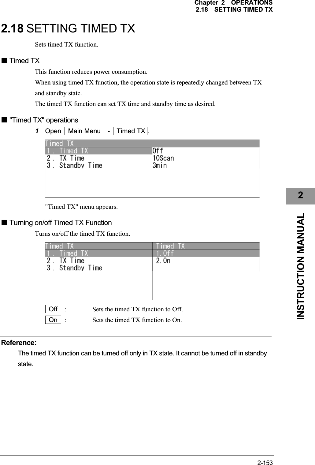
![Chapter 2OPERATIONS2.18SETTING TIMED TX 2-154 Setting TX Time Sets the number of antenna rotation. Turn the [MULTI] control to set the TX time. TX time can be adjusted between 0 and 99Scan. Setting Standby Time Sets the time for standby state. Turn the [MULTI] control to set the Standby Time. The standby time can be adjusted between 0 and 99min.](https://usermanual.wiki/Japan-Radio/NKE2063.Users-Manual-3/User-Guide-1644966-Page-78.png)