Japan Radio NKE2063 MARINE RADAR User Manual NKE2063UserMan
Japan Radio Co Ltd. MARINE RADAR NKE2063UserMan
Contents
- 1. Users Manual 1
- 2. Users Manual 2
- 3. Users Manual 3
- 4. Users Manual 4
Users Manual 4
Chapter 3
TRUE AND FALSE ECHOES ON DISPLAY
3.1
RADAR WAVE WITH THE HORIZON
3-1
3
INSTRUCTION MANUAL
Chapter 3
TRUE AND FALSE ECHOES ON
DISPLAY
The radar operator has a role of interpreting the radar displays to provide his best aid in
maneuvering the ship.
For this purpose, the operator has to observe the radar displays after fully understanding
the advantages and disadvantages that the radar has.
For better interpretation of radar display, it is important to gain more experiences by
operating the radar equipment in fair weathers and comparing the target ships watched
with the naked eyes and their echoes on the radar display.
The radar is mainly used to monitor the courses of own ship and other ships in open seas,
to check buoys and other nautical marks when entering a port, to measure own ship’s
position in the coastal waters relative to the bearings and ranges of the shore or islands
using a chart, and to monitor the position and movement of a heavy rain if it appears on
the radar display. Various types of radar display will be explained below.
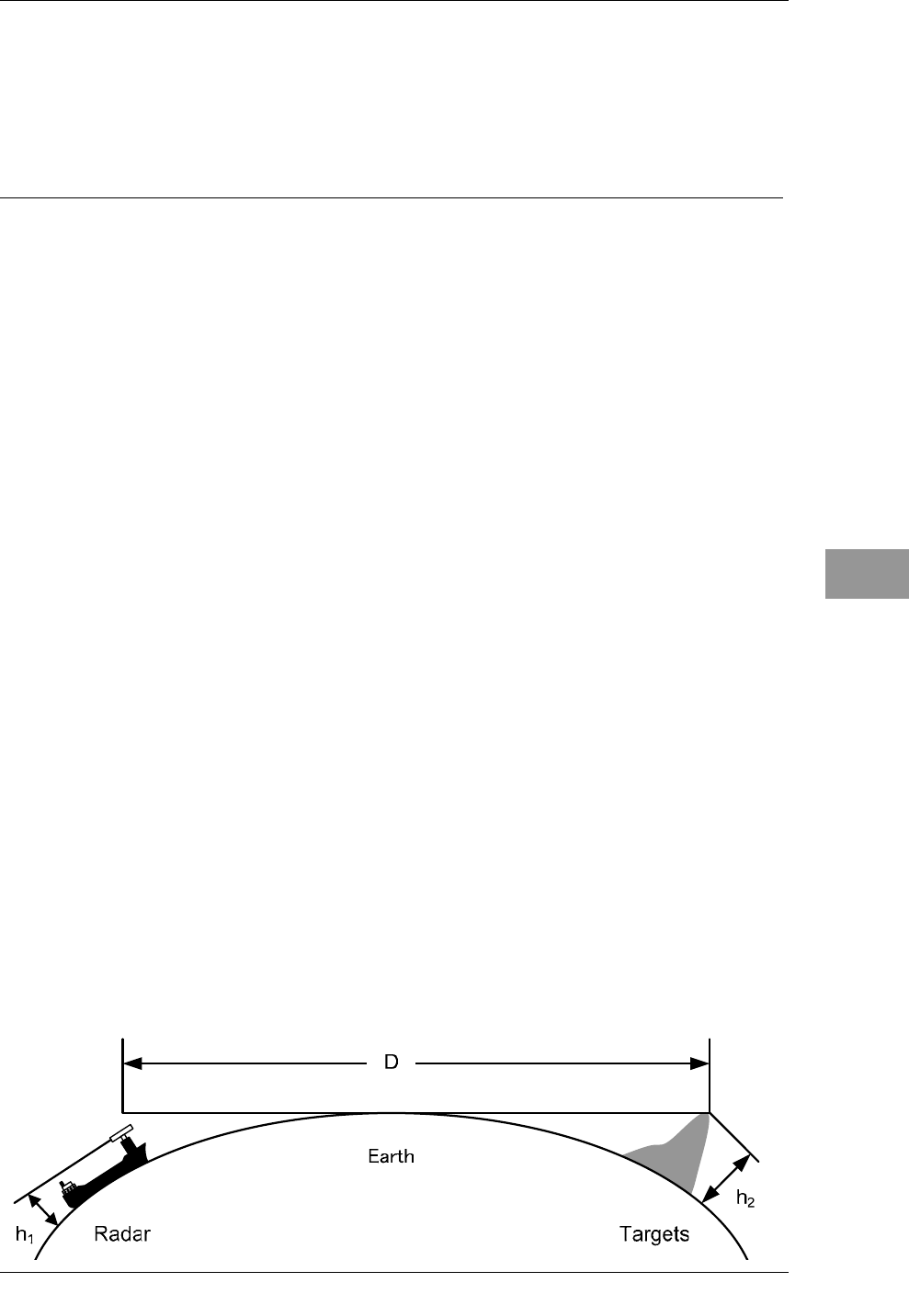
3.1 RADAR WAVE WITH THE HORIZON
Radar beam radiation has the nature of propagating nearly along the curved surface of
the earth. The propagation varies with the property of the air layer through which the
radar beam propagates. In the normal propagation, the distance (D) of the radar wave to
the horizon is approximately 10% longer than the distance to the optical horizon. The
distance (D) is given by the following formula:
D=2.23(h1 + h2)(nm)
h1: Height (m) of radar scanner above sea level
h2: Height (m) of a target above sea level
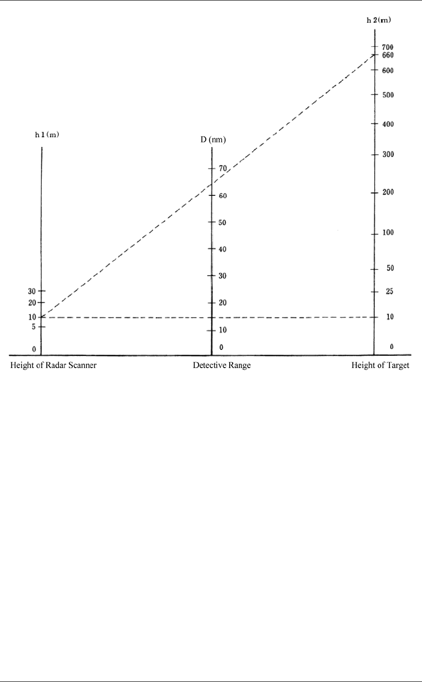
Fig. 3.1-1 is a diagram for determining the maximum detection range of a target that is
limited by the curve of the earth surface in the normal propagation.
Fig. 3.1-1
Chapter 3
TRUE AND FALSE ECHOES ON DISPLAY
3.1
RADAR WAVE WITH THE HORIZON
3-2
When the height of own ship's scanner is 10 m for instance,
(a) A target that can be detected at the radar range of 64 nm on the radar display is
required to have a height of 660 m or more.
(b) If the height of a target is 10 m, the radar range has to be approx. 15 nm.
However, the maximum radar range at which a target can be detected on the
radar display depends upon the size of the target and the weather conditions, that
is, the radar range may increase or decrease depending upon those conditions.
Chapter 3
TRUE AND FALSE ECHOES ON DISPLAY
3.2
REFLECTION FROM TARGET
3-3
3
INSTRUCTION MANUAL
3.2 REFLECTION FROM TARGET
The signal intensity reflected from a target depends not only on the height and size of the
target but also on its material and shape. The echo intensity from a higher and larger
target is not always higher in general.
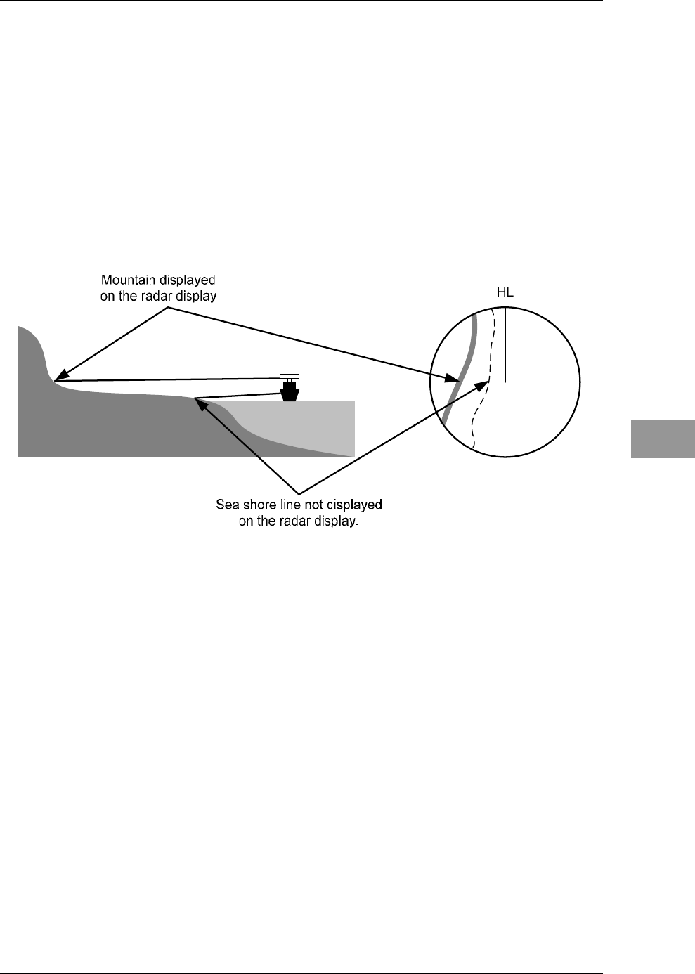
In particular, the echo from a coast line is affected by the geographic conditions of the
coast. If the coast has a very gentle slop, the echo from a mountain of the inland appears
on the radar display, as shown in Fig. 3.2-1. Therefore, the distance to the coast line
should be measured carefully.
Fig. 3.2-1

Chapter 3
TRUE AND FALSE ECHOES ON DISPLAY
3.3
SEA CLUTTER AND RAIN AND SNOW CLUTTER
3-4
3.3 SEA CLUTTER AND RAIN AND SNOW
CLUTTER
In addition to the echo required for observing ships and land radar video image also
includes unnecessary echo, such as reflection from waves on the sea surface and
reflection from rain and snow. Reflection from the sea surface is called "sea clutter," and
reflection from rain and snow is called "rain and snow clutter," and those spurious waves
must be eliminated by the clutter rejection function.
3.3.1 SEA CLUTTER
Sea clutter appears as an image radiating outwardly from the center of the radar display
and changing depending on the size and the shape of waves. Generally, as waves become
larger, image level of the sea clutter is intensified and the clutter far away is also
displayed. When waves are large and the sea clutter level is high, it is difficult to
distinguish sea clutter from a small boat whose reflection intensity is weak.
3.3.2 RAIN AND SNOW CLUTTER
Rain and snow clutter is a video image that appears in a location where rain or snow is
falling. The image changes according to the amount of rain (or the amount of snowfall).
As precipitation increases, the image of rain and snow clutter becomes intensified on the
radar display, and in the case of localized heavy rain, an image similar to the image
indicating land is displayed in some cases. Furthermore, because radio waves tend to
attenuate due to rain and snow, the ability to detect a target in the rain and snow clutter
or a target beyond the rain and snow clutter may decrease
3.3.3 COPING WITH SEA CLUTTER AND RAIN AND SNOW
CLUTTER
When the weather is bad and the ocean is rough, reducing the pulse width will reduce the
influence by spurious waves, and also the spurious wave rejection function effectively
works; therefore, the use of short pulse is effective when the weather is bad. By using
image processing functions "3Scan COREL" to "5Scan COREL", it is expected that
spurious waves are further suppressed. Since optimal settings for those items can be
automatically made by using the function mode, it is recommended that STORM or
RAIN be used by selecting the function mode when the weather is bad. For details of the
function mode, see Section "2.14 FUNCTION KEY SETTINGS".
However, these functions may make some targets invisible, particularly targets with
higher speeds.
Chapter 3
TRUE AND FALSE ECHOES ON DISPLAY
3.4
FALSE ECHOES
3-5
3
INSTRUCTION MANUAL
3.4 FALSE ECHOES
The radar observer may be embarrassed with some echoes that do not exist actually.
These false echoes appear by the following causes that are well known:
3.4.1 SHADOW
When the radar scanner is installed near a funnel or mast, the echo of a target that exists
in the direction of the funnel or mast cannot appear on the radar display because the
radar beam is reflected on the funnel or mast. Whether there are some false echoes due to
shadows can be checked monitoring the sea clutter returns, in which there may be a part
of weak or no returns. Such shadows appear always in the same directions, which the
operator should have in mind in radar operation.
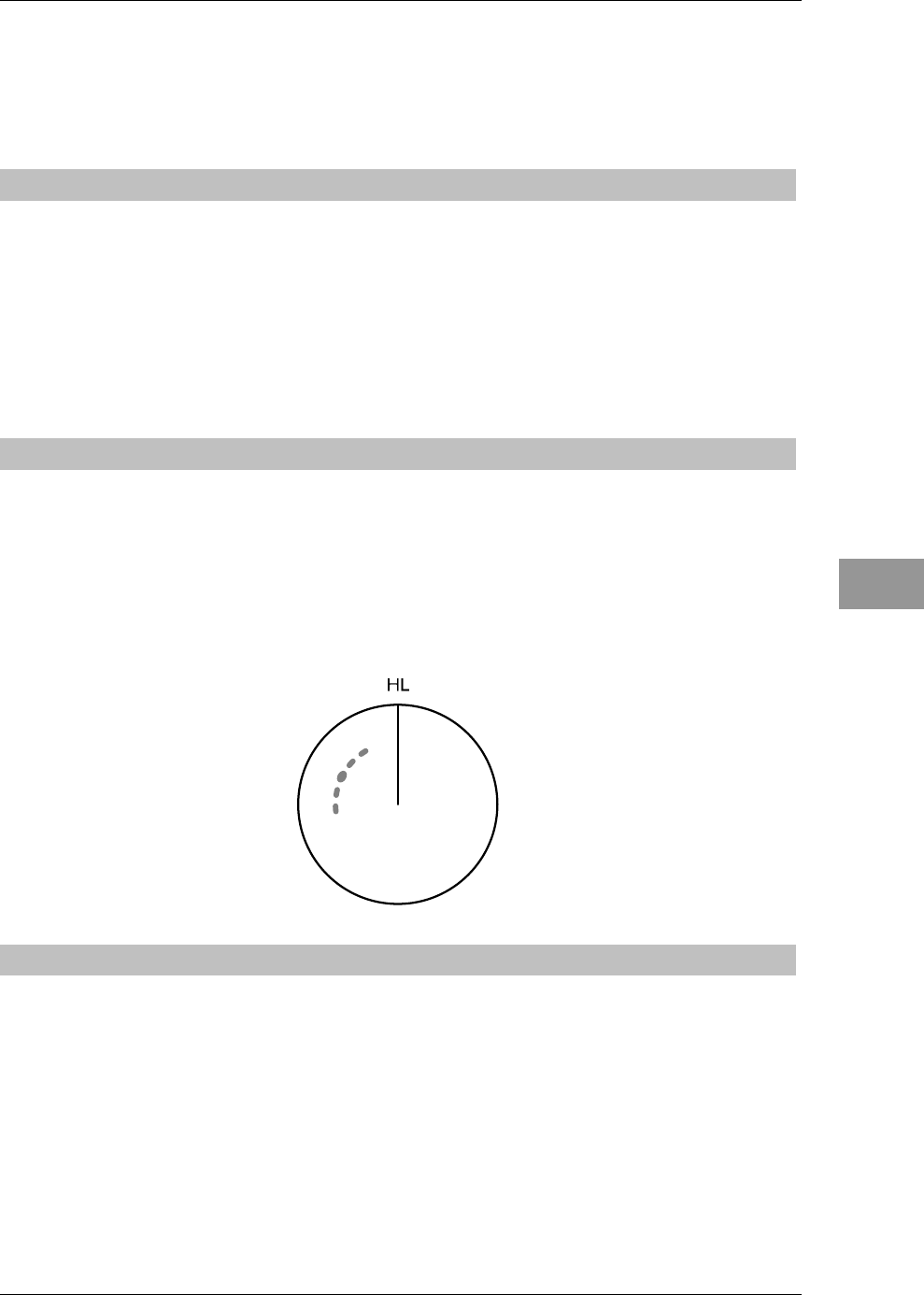
3.4.2 SIDE LOBE EFFECT
A broken-line circular arc may appear at the same range as the main lobe of the radar
beam on the radar display. This type of false echo can easily be discriminated when a
target echo appears isolated.(See Fig. 3.4-1.)
Fig. 3.4-1
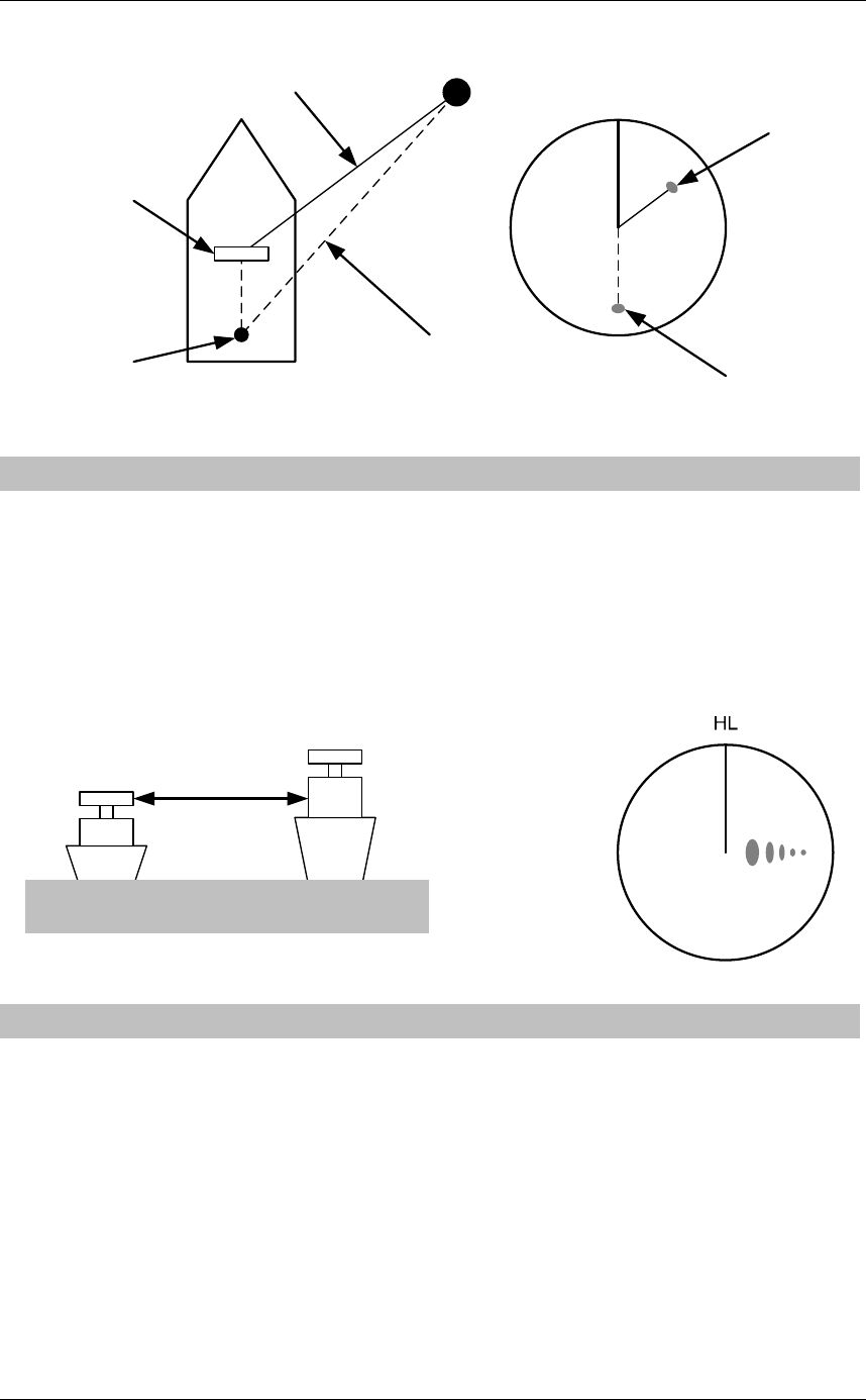
3.4.3 FALSE ECHO BY SECONDARY REFLECTION
When a target exists near own ship, two echoes from the single target may appear on the
radar display.
One of those echoes is the direct echo return from the target and the other is the
secondary reflection return from a mast or funnel that stands in the same direction as
shown in Fig. 3.4-2.
Chapter 3
TRUE AND FALSE ECHOES ON DISPLAY
3.4
FALSE ECHOES
3-6
Fig. 3.4-2
Radar
scanner
Funnel
HL
Direct microwave
Secondary reflection
of microwave
Actual target
False echo from funnel
3.4.4 FALSE ECHO BY MULTIPLE REFLECTION
When there is a large structure or ship with a high vertical surface near own ship as
shown in Fig. 3.4-3, multiple refection returns may appear on the radar display. These
echoes appear in the same intervals, of which the nearest echo is the true echo of the
target.
Fig. 3.4-3
3.4.5 SECOND TIME ECHOES
The maximum radar detection range depends upon the height of the scanner and the
height of a target as described in the Section "3.1 RADAR WAVE WITH THE
HORIZON". If a so-called "duct" occurs on the sea surface due to a certain weather
condition, however, the radar beam may propagate to a abnormally long distance, at
which a target may be detected by the radar.
For instance, assuming that the pulse length is MP3 (on the repetition frequency of 1400
Hz), the first pulse is reflected from a target at about 58 NM or more and received during
the next pulse repetition time. In this case, a false echo (second time echo) appears at a
position that is about 58 NM shorter than the actual distance. If the false echo appears at
5 NM on the radar display, the true distance of the target is 5+58=63 NM. On the pulse
Chapter 3
TRUE AND FALSE ECHOES ON DISPLAY
3.4
FALSE ECHOES
3-7
3
INSTRUCTION MANUAL
length is SP1 (on the repetition frequency of 2250 Hz), a false echo may appear at a
position that is about 36 NM shorter than the actual distance.
This type of false echo can be discriminated by changing over the range scale (the
repetition frequency), because the distance of the target changes accordingly.
If second time echo is appeared, the use of Economy mode in PRF menu is effective.
Otherwise, Stagger Trigger menu set to on. (Refer to Section "4.6 SCANNER" of
INSTALLATION MANUAL.)
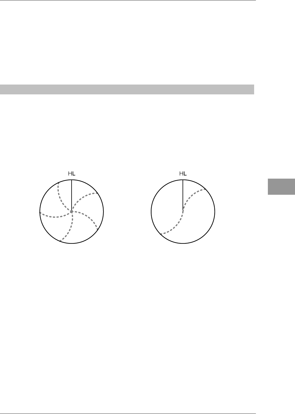
3.4.6 RADAR INTERFERENCE
When another radar equipment using the same frequency band as that on own ship is
near own ship, a radar interference pattern may appear on the radar display. This
interference pattern consists of a number of spots which appear in various forms. In
many cases, these spots do not always appear at the same places, so that they can be
discriminated from the target echoes.(See Fig. 3.4-4.)
Fig. 3.4-4
If radar equipment causing an interference pattern and this radar are of the same model,
their transmitting repetition frequency is nearly the same. As a result, interference
patterns may be displayed concentrically.
In this case, the interference patterns cannot be eliminated by using only the interference
reflector function, so press the [TX/PRF] key several times to fine-tune the transmitting
repetition frequency.
An interference suppressing effect can be heightened by applying a different transmitting
repetition frequency to the interference pattern source radar and this radar.

Chapter 3
TRUE AND FALSE ECHOES ON DISPLAY
3.5
DISPLAY OF RADAR TRANSPONDER (SART)
3-8
3.5 DISPLAY OF RADAR TRANSPONDER
(SART)
The SART (Search and rescue Radar Transponder) is a survival device authorized by the
GMDSS (Global Maritime Distress and Safety System), which is used for locating
survivors in case that a distress accident occurs at sea. The SART is designed to operate
in the 9 GHz frequency band. When receiving the 9 GHz radar signal (interrogating
signal) transmitted from the radar equipment on a rescue ship or search aircraft, the
SART transmit a series of response signals to inform the distress position to the rescue
and search party.
Perform the following settings to display SART on the radar screen.
1. Range: 6 NM or 12 NM
2. [SEA] control: Turning to the minimum position (counterclockwise fully)
3. Automatic sea clutter suppression function: Off
4. Tuning function: Off (for less clutter)
5. IR: Off
6. Processing: Off
Note:
z When performing the settings 1 to 6 above to display the SART signal, targets
around own ship will disappear from the radar display. So it is necessary to
exercise full surveillance over the conditions around own ship by visual watch in
order to avoid any collision or stranding.
If two or more sets of radar equipment are installed on own ship, use one set of
9 GHz band radar for detection of the SART signal and operate others as
normal radars for avoiding collision, monitoring targets around own ship, and
checking on own ship's position and avoidance of stranding.
After the detection of SART signal, the radar adjustment is required for general
navigation.
Chapter 4
MAINTENANCE
4.1
ROUTINE MAINTENANCE
4-1
4
INSTRUCTION MANUAL
Chapter 4 MAINTENANCE
4.1 ROUTINE MAINTENANCE
DANGER
Never carry out internal inspection or repair work of the equipment
by users.
Inspection or repair work by unauthorized personnel may result in
fire hazard or electric shock.
For inspection and repair work of equipment components, consult
with our branch office, branch shop, sales office, or our distributor
in your district.
When conducting maintenance, make sure to turn the main power
off.
Failure to comply may result in electrocution.
Turn off the main power before cleaning the equipment. Especially
when a rectifier is used, make sure to turn it off since voltage is
still outputted from the rectifier even after the indicator and the
radar are turned off. Failure to comply may result in equipment
failure, or death or serious injury due to electric shock.
For operating the radar equipment in the good conditions, it is necessary to make the
maintenance work as described below. If maintenance is made properly, troubles will
reduce. It is recommended to make regular maintenance work.
Common points of maintenance for each unit are as follow:
Clean the equipment.
Remove the dust, dirt, and sea water rest on the equipment cabinet with a piece of dry
cloth. Especially, clean the air vents with a brush for good ventilation.
Chapter 4
MAINTENANCE
4.2
MAINTENANCE ON EACH UNIT
4-2
4.2 MAINTENANCE ON EACH UNIT
4.2.1 SCANNER UNIT NKE-2042, 2043, 2062/HS, 2063/HS,
2103-4/4HS/6/6HS
DANGER
When conducting maintenance work on the antenna, make sure to
turn its main power off.
Failure to comply may result in electrocution or injuries.
Make sure to turn off the antenna operation switch.
Failure to comply may result in injuries caused by physical contact
with the rotating antenna.
Do not touch the radiator. Even if the power is turned off, the
radiator may be rotated by the wind.
After the work, turn "ON" the scanner unit safety switch.
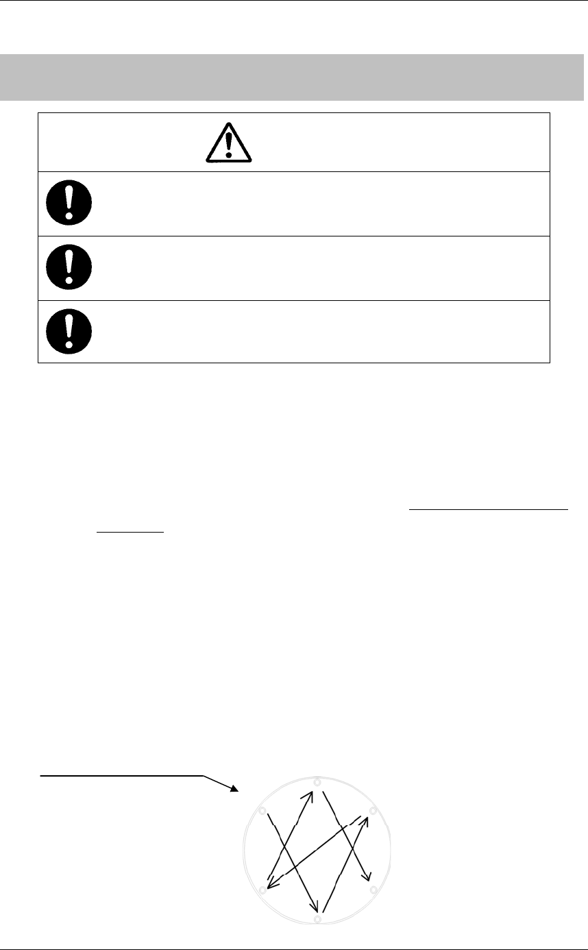
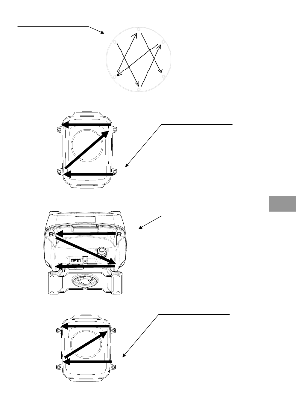
Precautions in Mounting the Cover
When the cover is removed for regular checkup and replacement of parts and refitted after
such work, the procedures of fastening bolts shall be taken with the following precautions:
yThe proper fastening torque of the fitting bolts (M8) is 1176 to 1470 N•cm (120 to
150kgf•cm) (which makes the inside water-tight and protects the packings against
permanent compressive strain). The packings start producing from the cover at a
torque of approximately 1470N•cm (150kgf•cm). Do not fasten the bolts with a
torque exceeding the specified value. Otherwise, the screws may be broken.
yUse an offset wrench of 11 mm × 13 mm or a double-ended wrench of 13 mm × 17
mm (not longer than 200 mm).
yScrew all the bolts by hand first to prevent them playing, then fasten them evenly in
order not to cause one-sided fastening. (Fasten the bolts with 25% of the required
torque at the first step.)
*: Fasten the bolts in the diagonal order.
ճ
ն
ձ
մ
յ
ղ
NKE-2042 Cover Bolt
Tightening Procedure
4-M5 (stainless steel) bolt
Tightening torque: 120 to 150 kgf/cm
Chapter 4
MAINTENANCE
4.2
MAINTENANCE ON EACH UNIT
4-3
4
INSTRUCTION MANUAL
մճ
ղձ
մ ճ
ղձ
ձ
ղ
ճմ NKE-2063/HS Cover Bolt
Tightening Procedure
4-M8 (stainless steel) bolt
Tightening torque: 120 to 150 kgf/cm
ճ
ն
ձ
մ
յ
ղ
NKE-2043 Cover Bolt
Tightening Procedure
4-M5 (stainless steel) bolt
Tightening torque: 120 to 150 kgf/cm
NKE-2103-4/4HS/6/6HS Cover
Bolt Tightening Procedure
4-M8 (stainless steel) bolt
Tightening torque: 120 to 150 kgf/cm
NKE-2062 Cover Bolt
Tightening Procedure
4-M8 (stainless steel) bolt
Tightening torque: 120 to 150 kgf/cm

Chapter 4
MAINTENANCE
4.2
MAINTENANCE ON EACH UNIT
4-4
Radiator
Note:
z If the radiator front face (radiation plane) is soiled with smoke, salt, dust, paint or
birds’ droppings, wipe it with a piece of soft cloth wetted with alcohol or water
and try to keep it clean at all times. Otherwise, radar beam radiation may
attenuate or reflect on it, resulting in deterioration of radar performance.
z Never use solvents of gasoline, benzine, trichloroethylene and ketone for
cleaning.
Otherwise, the radiation plane may deteriorate.
Check up and clean the radiator.
Rotating section
Oiling gears
Apply grease evenly to the tooth surfaces of the main shaft drive gear and the encoder
drive gear with a spreader or brush. Oiling in short intervals is more effective to prevent
the gears from wear and tear and extend their service life, but oil at least every six
months.
Use the grease of Mobilux 2 of Mobil Oil.
Driving motor
i) Attenuator
Greasing is not necessary unless there is oil leakage.
ii) Motor
The life span of the brush itself is 2000 hours. When the brush is worn out to a half
of the entire length, replace it.
The communicator must be kept clean all the time. If carbon dust is stuck and cannot
be removed with a dry cloth, polish the section with sand paper of No.150 to 400.
The carbon brush can be removed by removing the caps on both sides of the bottom
of the motor.
Carbon brush
Communicator contact side
Spring
Chapter 4
MAINTENANCE
4.2
MAINTENANCE ON EACH UNIT
4-5
4
INSTRUCTION MANUAL
Table 4.2-1 List of replacement carbon brushes
Scanner unit
model name Item name Model name JRC code Replacement
quantity
JMA-3316 Carbon brush 54531-01 BRXP05247 2
JMA-3336 Carbon brush 54531-01 BRXP05247 2
Mounting legs
Check the mounting legs and mounting bolts of the scanner unit case for corrosion at
intervals and maintain them to prevent danger. Apply paint to them once a half year
because painting is the best measure against corrosion.
4.2.2 DISPLAY UNIT NCD-2182
WARNING
When cleaning the display screen, do not wipe it too strongly with
a dry cloth. Also, do not use gasoline or thinner to clean the
screen.
Failure to comply will result in damage to the screen surface.
Dust accumulated on the screen will reduce clarity and darken the video.
For cleaning it, wipe it with a piece of soft cloth (flannel or cotton). Do not wipe it
strongly with a piece of dry cloth nor use gasoline or thinner.

Chapter 4
MAINTENANCE
4.3
PERFORMANCE CHECK
4-6
4.3 PERFORMANCE CHECK
Make operational check on the radar equipment regularly and if any problem is found,
investigate it immediately.
Pay special attention to the high voltage sections in checking and take full care that no
trouble is caused by any error or carelessness in measurement. Take note of the results of
checking, which can be used effectively in the next check work.
Operational check shall be made in accordance with Table 4.3-1 Function Check List in
the order as specified in it.
Table 4.3-1 Function Check List
Equipment Item to be checked Criteria Remarks
Transmitter-receiver
Unit Tuning LED of Receiver The LED is lighting during operation 48NM range
Video and echoes on the
screen
Sensitivity
LCD brilliance can be
controlled correctly
Various markers
Various numerical
indications
Lighting
Can be correctly controlled
Safety Switch
Various Currents and
Voltages
See "■ Sensor Test" in "4.3.8 SELF
TEST".
Communication Lines See "■ Line Test" in "4.3.8 SELF TEST".
Memory See "■ Memory Test" in "4.3.8 SELF
TEST".
Panel See "■ Key Test" in "4.3.8 SELF TEST".
Checking the Monitor See "■ Monitor Display Test" in "4.3.8
SELF TEST".
Magnetron Current See "4.3.4 SCANNER INFORMATION".
Error Logging Display See 4.3.6 ERROR LOG.
Display Unit
System Information Display See 4.3.2 SYSTEM INFORMATION and
4.3.3 SYSTEM TIME.
Chapter 4
MAINTENANCE
4.3
PERFORMANCE CHECK
4-7
4
INSTRUCTION MANUAL
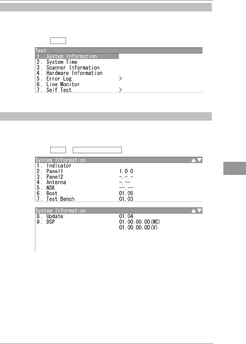
4.3.1 TEST MENU
The performance status of this radar equipment can be checked on the Test Menu.
"Test" operations
1Open Test from the Main Menu.
"Test" menu appears.
4.3.2 SYSTEM INFORMATION
Displays the current system information (software version information).
"System INFO" operations
1Open Test - System Information .
The software version is displayed.
Chapter 4
MAINTENANCE
4.3
PERFORMANCE CHECK
4-8
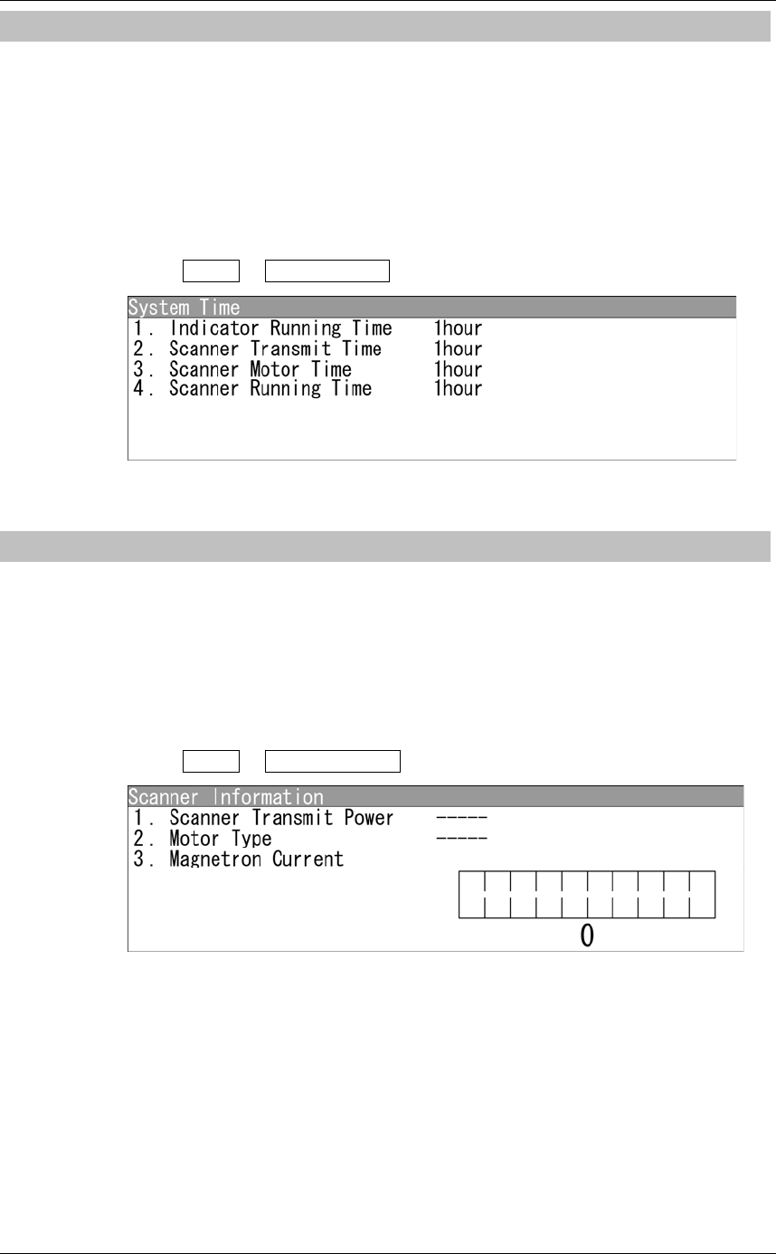
4.3.3 SYSTEM TIME
Displays the following system time information.
yIndicator Running Time
yScanner Transmit Time
yScanner Motor Time
yScanner Running Time
"System Time" operations
1Open Test - System Time .
"System Time" menu appears.
4.3.4 SCANNER INFORMATION
Displays the following scanner information.
yTransmitted output power
yMotor Type
yMagnetron Current
"Scanner Information" operations
1Open Test - Scanner INFO .
"Scanner Information" menu appears.
Chapter 4
MAINTENANCE
4.3
PERFORMANCE CHECK
4-9
4
INSTRUCTION MANUAL
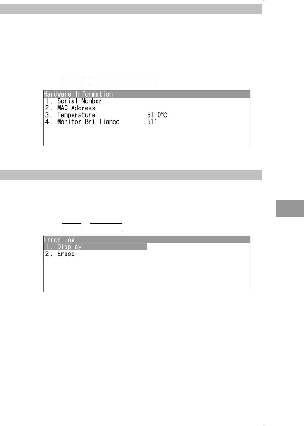
4.3.5 HARDWARE INFORMATION
Displays the following hardware information.
ySerial Number
yMAC Address
yTemperature
"Hardware Information" operations
1Open Test - Hardware Information .
"Hardware Information" menu appears.
4.3.6 ERROR LOG
The error log displays previously occurred system alarms with the dates and times when
they occurred.
"Error Log" operations
1Open Test - Error Log .
"Error Log" menu appears.
Chapter 4
MAINTENANCE
4.3
PERFORMANCE CHECK
4-10
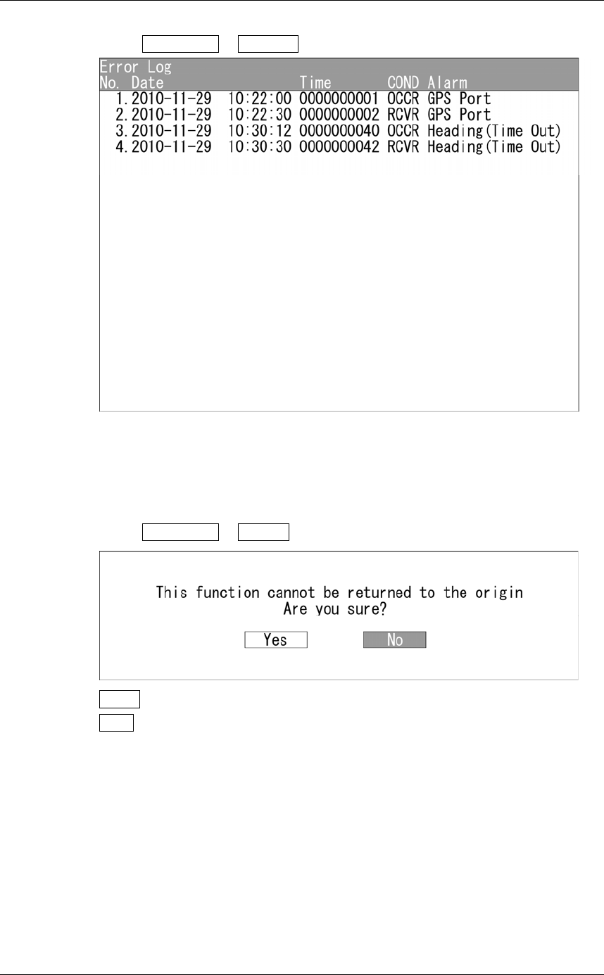
Displaying Error Log
1Open Error Log - Display .
"Error Log" menu appears.
For details of alarms, refer to "4.5.1 LIST OF ALARMS AND OTHER
INDICATIONS".
Erasing Error Log
1Open Error Log - Erase .
Yes : Erases the error log.
No : Does not erase the error log.
Chapter 4
MAINTENANCE
4.3
PERFORMANCE CHECK
4-11
4
INSTRUCTION MANUAL
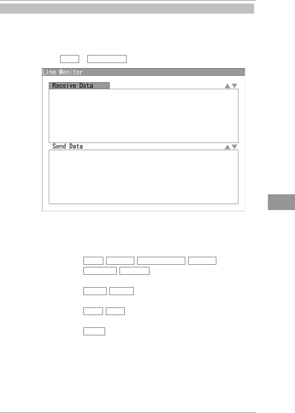
4.3.7 LINE MONITOR
Serial communication data can be seen on the built-in Line monitor.
Line monitor can be used to make sure that the serial data are received properly.
"Line Monitor" operations
1Open Test - Line Monitor .
"Line Monitor" menu appears.
Receive Data: The received serial communication data are displayed.
Send Data: The transmitted serial communication data are displayed.
Soft key 1: GPS NMEA1 Gyro/Compass NMEA2
Keyboard Scanner
Press the soft key 1 to select the port for serial communication data.
Soft key 2: ASCII Binary
Press the soft key 2 to switch the display.
Soft key 3: Stop Play
Press the soft key 3 to stop/start scrolling.
Soft key 4: Clear
Press the soft key 4 to clear all listed serial communication data.
Chapter 4
MAINTENANCE
4.3
PERFORMANCE CHECK
4-12
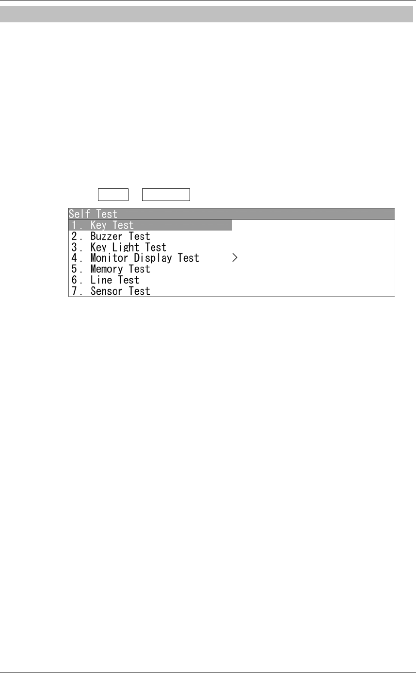
4.3.8 SELF TEST
The following tests can be performed.
yKey Test
yBuzzer Test
yKey Light Test
yMonitor Display Test
yMemory Test
yLine Test
ySensor Test
"Self Test" operations
1Open Test - Self Test .
Chapter 4
MAINTENANCE
4.3
PERFORMANCE CHECK
4-13
4
INSTRUCTION MANUAL
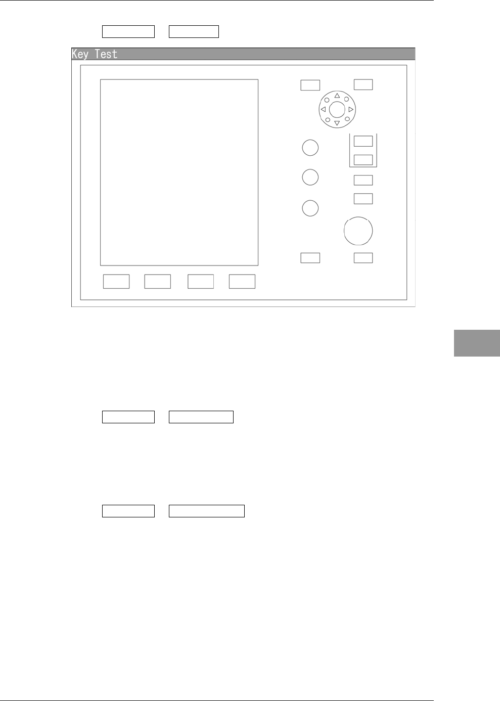
Key Test
1Open Self Test - Key Test .
Operation key video will be displayed.
When pressing each key, the corresponding operation key is color-inverted on the
display.
Press the [CLEAR] key to turn off the operation keys.
Buzzer Test
1Open Self Test - Buzzer Test .
The buzzer will sound.
The buzzer automatically stops after it sounds for a certain time.
The buzzer will sound regardless of the buzzer setting.
Key Light Test
1Open Self Test - Key Light Test .
The brightness of the operation panel is gradually intensified.
Chapter 4
MAINTENANCE
4.3
PERFORMANCE CHECK
4-14
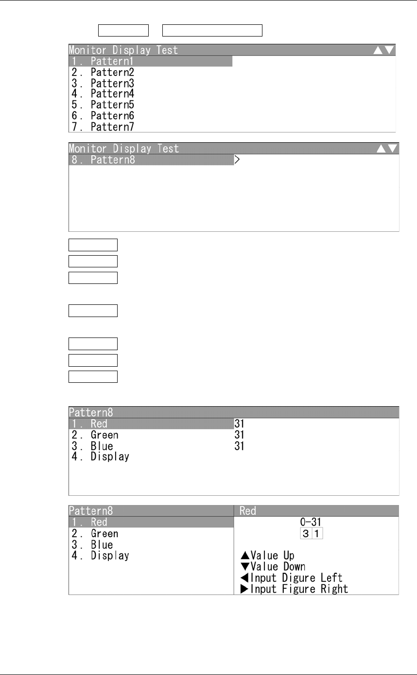
Monitor Display Test
1Open Self Test - Monitor Display Test .
Pattern1 : All colors are filled with white.
Pattern2 : A white box is displayed on the black background of 1024 × 768 dots.
Pattern3 : Displays rectangle × 2, circle × 2, and cross-shape× 9 (white lines on the
black background).
Pattern4 : Displays "H" of 9 dots × 9 dots on the entire screen (white character
on the black background).
Pattern5 : Gray scale display (16 levels)
Pattern6 : Displays a color bar.
Pattern7 : The square figure of a specified RGB value is shown at the center of
the display.
Input the value.
Turn the [MULTI] control to set the value.
The value can be set between 0 and 31.
Operate the same way for the other settings.
Chapter 4
MAINTENANCE
4.3
PERFORMANCE CHECK
4-15
4
INSTRUCTION MANUAL
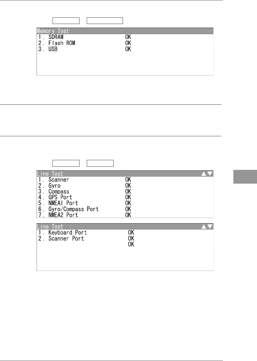
Memory Test
1Open Self Test - Memory Test .
When no abnormality is found, "OK" is displayed. When an abnormality is found,
"NG" is displayed.
Reference:
More time may be required for USB detection in order to acquire "OK".
Do not remove USB during memory test.
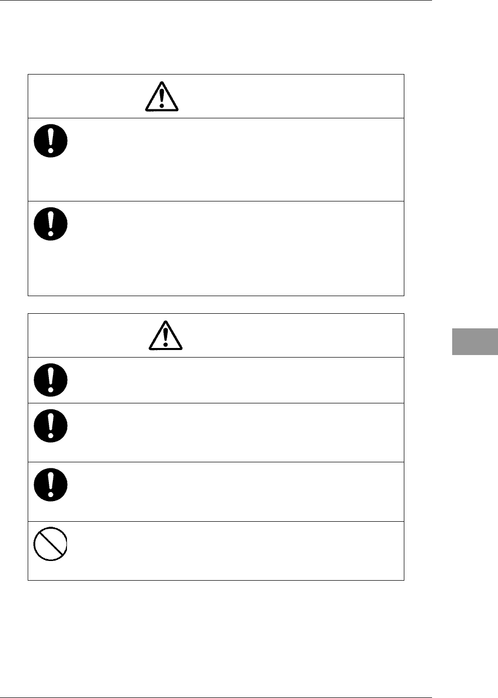
Line Test
1Open Self Test - Line Test .
When no abnormality is found, "OK" is displayed. When an abnormality is found,
"NG" is displayed.

Chapter 4
MAINTENANCE
4.3
PERFORMANCE CHECK
4-16
Sensor Test
1Open Self Test - Sensor Test .
When no abnormality is found, "OK" is displayed. When an abnormality is found,
"NG" is displayed.
Chapter 4
MAINTENANCE
4.4
REPLACEMENT OF MAJOR PARTS
4-17
4
INSTRUCTION MANUAL
4.4 REPLACEMENT OF MAJOR PARTS
The system includes parts that need periodic replacement. The parts should be replaced
as scheduled. Use of parts over their service life can cause a system failure.
WARNING
Direct exposure to electromagnetic waves at close range will have
adverse effects on the human body. When it is necessary to get
close to the antenna for maintenance or inspection purposes,
make sure to turn the indicator power switch to "OFF" or "STBY."
Direct exposure to electromagnetic waves at close range will have
adverse effects on the human body.
When conducting maintenance work, make sure to turn off the
power and unplug the power connector J1 of the display unit so
that the power supply to the equipment is completely cut off.
Some equipment components can carry electrical current even
after the power switch is turned off, and conducting maintenance
work without unplugging the power connector may result in
electrocution, equipment failure, or accidents.
CAUTION
Make sure to shut off the main power before replacing parts.
Failure to comply may result in electrocution or equipment failure.
When replacing magnetrons, make sure to shut off the main power
and let the equipment stand for more than 5 minutes to discharge
the high-voltage circuit.
Failure to comply may result in electrocution.
Make sure to take off your watch when your hand must get close
to the magnetron.
Failure to comply may result in damage to the watch since the
magnetron is a strong magnet.
Do not directly touch the inverter circuit of the LCD display with a
bare hand since high voltage temporarily remains in the circuit
even after the main power is shut off.
Failure to comply may result in electrocution.

Chapter 4
MAINTENANCE
4.4
REPLACEMENT OF MAJOR PARTS
4-18
Parts Required for Periodic Replacement
Here are parts required for periodic replacement.
Part name Interval
1. Magnetron 4,000 hours
2. Motor 10,000 hours
3. LCD backlight 50,000 hours
4. Fan motor 20,000 hours
Chapter 4
MAINTENANCE
4.5
FAULT FINDING
4-19
4
INSTRUCTION MANUAL
4.5 FAULT FINDING
In case of semiconductor circuits, it is deemed that there are few cases in which the used
semiconductor devices have inferior quality or performance deterioration except due to
insufficient design or inspection or by other external and artificial causes. In general, the
relatively many causes are disconnection in a high-value resistor due to moisture, a
defective variable resistor and poor contact of a switch or relay.
Some troubles are caused by defective parts, imperfect adjustment (such as tuning
adjustment) or insufficient service (such as poor cable contact). It will also be effective
to check and readjust these points.
4.5.1 LIST OF ALARMS AND OTHER INDICATIONS
If any of the following alarm occurs, the system displays the alarm message in red in
order to attract the attention of operator. Other messages are displayed with the suitable
color which is yellow or blue depending on the level of message importance.
Alarm: Red ࣭Collision-related Alarm
࣭Navigation Alarm
࣭System Alarm
Caution: Yellow ࣭System Warning
Status: Blue ࣭Operation Information
The following table shows alarms and other indications the system displays.
Table 4.5-1 Alarm list
Alarm name
(Japanese)
Alarm name
(English) Class Description
㆙ሗ࢚࣮ࣛ Alarm Error Alarm Cannot send the alarm because of insufficient message buffer for
alarm task.
Table 4.5-2 Alarm list of system alarm: scanner
Alarm name
(Japanese)
Alarm name
(English) Class Description
✵୰⥺ Ᏻ SW ࢜ࣇ Scanner(SSW Off) Alarm The safety switch OFF bit of scanner communication data is set.
✵୰⥺ AZI Scanner(AZI) Alarm The BP error bit of scanner communication data is set.
✵୰⥺ HL Scanner(HL) Alarm The BZ error bit of scanner communication data is set.
✵୰⥺ ኚㄪ㧗ᅽ Scanner(MHV) Alarm The high-voltage modulator error bit of scanner communication
data is set.
✵୰⥺ ↓㏻ಙ Scanner(Time Out) Alarm No reply from the scanner after data transmission.

Chapter 4
MAINTENANCE
4.5
FAULT FINDING
4-20
Alarm name
(Japanese)
Alarm name
(English) Class Description
✵୰⥺ ࢹ࣮ࢱ Scanner(Data) Alarm Collision occurs when transmitting data to the scanner.
Checksum of the received data is different.
✵୰⥺ EEPROM Scanner(EEPROM) Alarm Stored value error is returned from the scanner when the initial
adjustment data is requested.
The save operation is not completed when data save is requested to
scanner EEPROM.
✵୰⥺ ࣄ࣮ࢱ㟁ᅽ Scanner(Heater) Alarm The MAG heater voltage error bit of scanner communication data
is set.
✵୰⥺ ㏫ᅇ㌿ Scanner(Reverse) Alarm The reverse rotation alarm bit of scanner communication data is set.
✵୰⥺ ࣅࢹ࢜ Scanner(Video) Alarm The VIDEO error bit of scanner communication data is set.
✵୰⥺ ࢺ࣮ࣜ࢞ Scanner(Trigger) Alarm The TRIGGER error bit of scanner communication data is set.
✵୰⥺ ࣇࣥ 1 Scanner(Fan 1) Alarm The FAN error bit (FAN 1) of scanner communication data is set.
✵୰⥺ ࣇࣥ 2 Scanner(Fan 2) Alarm The FAN error bit (FAN 2) of scanner communication data is set.
✵୰⥺ ࣮ࣔࢱ㟁ὶ Scanner(Motor) Alarm The motor current error of scanner communication data is set.
Table 4.5-3 Alarm list of system alarm: display unit
Alarm name
(Japanese)
Alarm name
(English) Class Description
᧯స㒊 1↓㏻ಙ Keyboard1(Time Out) Alarm No reply from the control panel after data transmission.
᧯స㒊 2↓㏻ಙ Keyboard2(Time Out) Alarm No reply from the control panel after data transmission.
DSP ࣅࢹ࢜ DSP(Video) Alarm DSP detects VIDEO error.
DSP ࢺ࣮ࣜ࢞ DSP(Trigger) Alarm DSP cannot receive TI interrupt.
DSP AZI DSP(AZI) Alarm DSP cannot receive BP interrupt.
DSP HL DSP(HL) Alarm DSP cannot receive BZ interrupt.
DSP ฎ⌮␗ᖖ DSP Error Alarm Abnormal operation (infinite loop) of DSP.
Table 4.5-4 Alarm list of system alarm: external equipment communication
Alarm name
(Japanese)
Alarm name
(English) Class Description
GPS ࣏࣮ࢺ GPS Port Alarm Serial driver error occurs during COM1 port communication.
Gyro/Compass ࣏࣮ࢺ Gyro/Compass Port Alarm Serial driver error occurs during COM2 port communication.
NMEA1 ࣏࣮ࢺ NMEA1 Port Alarm Serial driver error occurs during COM3 port communication.
NMEA2 ࣏࣮ࢺ NMEA2 Port Alarm Serial driver error occurs during COM4 port communication.
Keyboard ࣏࣮ࢺ Keyboard Port Alarm Serial driver error occurs during COM5 port communication.
Scanner ࣏࣮ࢺ Scanner Port Alarm Serial driver error occurs during COM6 port communication.
ࢪࣕࣟ ↓㏻ಙ GYRO(Time Out) Alarm For heading equipment=Gyro, cannot receive valid sentences
(including checksum error) which had been received properly.

Chapter 4
MAINTENANCE
4.5
FAULT FINDING
4-21
4
INSTRUCTION MANUAL
Alarm name
(Japanese)
Alarm name
(English) Class Description
ࣟࢢ ↓㏻ಙ Log(Time Out) Alarm For speed equipment=log, cannot receive valid sentences
(including checksum error) which had been received properly.
ࢪࣕࣟ ㏻ಙࢹ࣮ࢱ GYRO(Data) Alarm For heading equipment=Gyro, the GYRO error bit of NSK
communication data is set.
ࣟࢢ ㏻ಙࢹ࣮ࢱ Log(Data) Alarm For speed equipment=log, the LOG error bit of NSK
communication data is set.
㔪㊰ ↓㏻ಙ Heading(Time Out) Alarm For heading equipment=compass, cannot receive valid NMEA
bearing sentences (including checksum error) which had been
received properly.
㔪㊰ ㏻ಙࢹ࣮ࢱ Heading(Data) Alarm For heading equipment=compass, cannot receive valid NMEA
bearing data which had been received properly.
2㍈ᑐᆅ ↓㏻ಙ 2AXG(Time Out) Alarm For speed equipment=2-axis log, cannot receive valid VBW
sentences (including checksum error) which had been received
properly.
2㍈ᑐᆅ ㏻ಙࢹ࣮ࢱ 2AXG(Data) Alarm For speed equipment=2-axis log, cannot receive valid VBW
ground data which had been received properly.
GPS ࢚࣮ࣛ GPS(Error) Status Failed to set GPS.
GPS ↓㏻ಙ GPS(Time Out) Alarm Cannot receive valid GPS sentences (including checksum error)
which had been received properly.
GPS ⨨ࢹ࣮ࢱ GPS(Position) Alarm Cannot receive valid position data which had been received
properly
GPS ᆅ⣔ࢹ࣮ࢱ GPS(Datum) Alarm Cannot receive valid geodetic data which had been received
properly
GPS ㏿ᗘࢹ࣮ࢱ GPS(Speed) Alarm For speed equipment=GPS, cannot receive valid speed data which
had been received properly
GPS ≧ែ GPS(Status) Alarm Received GPS fixing status error (invalid) data
Ỉ῝ ↓㏻ಙ Depth(Time Out) Alarm Cannot receive valid depth sentences (including checksum error)
which had been received properly
Ỉ῝ ㏻ಙࢹ࣮ࢱ Depth(Data) Alarm Cannot receive valid depth data which had been received properly
Ỉ ↓㏻ಙ TEMP(Time Out) Alarm Cannot receive valid water temperature sentences which had been
received properly
Ỉ ㏻ಙࢹ࣮ࢱ TEMP(Data) Alarm Cannot receive valid water temperature data which had been
received properly
㢼ྥ㢼㏿ ↓㏻ಙ Wind(Time Out) Alarm Cannot receive valid wind direction/wind velocity sentences
(including checksum error) which had been received properly
㢼ྥ㢼㏿㸦┿㸧 ㏻ಙ㺡㺼㺎㺞 Wind True(Data) Alarm Cannot receive valid water temperature data after valid wind
direction/wind velocity (true) data had been received properly

Chapter 4
MAINTENANCE
4.5
FAULT FINDING
4-22
Alarm name
(Japanese)
Alarm name
(English) Class Description
㢼ྥ㢼㏿㸦┦㸧 ㏻ಙ㺡㺼㺎㺞 Wind Relative(Data) Alarm Cannot receive valid water temperature data after valid wind
direction/wind velocity (relative) data had been received properly
ᅇ㢌⋡ ↓㏻ಙ Turn(Time Out) Alarm Cannot receive valid turning ratio sentences (including checksum
error) which had been received properly
ᅇ㢌⋡ ㏻ಙࢹ࣮ࢱ Turn(Data) Alarm Cannot receive valid turning ratio data which had been received
properly
⯦ゅ ↓㏻ಙ Rudder(Time Out) Alarm Cannot receive valid steering direction sentences (including
checksum error) which had been received properly
⯦ゅ ㏻ಙࢹ࣮ࢱ Rudder(Data) Alarm Cannot receive valid steering direction data which had been
received properly
AIS ↓㏻ಙ AIS(Time Out) Alarm For AIS function=On, cannot receive valid AIS data (including
checksum error) which had been received properly
AIS ㏻ಙࢹ࣮ࢱ AIS(Data) Alarm For AIS function=On, cannot receive valid AIS data which had
been received properly
AIS 㺏㺵㺎㺯 001 AIS(Alarm 001) Alarm For AIS function=On, an error from the AIS receiver is received
(ALR)
AIS 㺏㺵㺎㺯 002 AIS(Alarm 002) Alarm For AIS function=On, an error from the AIS receiver is received
(ALR)
AIS 㺏㺵㺎㺯 003 AIS(Alarm 003) Alarm For AIS function=On, an error from the AIS receiver is received
(ALR)
AIS 㺏㺵㺎㺯 004 AIS(Alarm 004) Alarm For AIS function=On, an error from the AIS receiver is received
(ALR)
AIS 㺏㺵㺎㺯 005 AIS(Alarm 005) Alarm For AIS function=On, an error from the AIS receiver is received
(ALR)
AIS 㺏㺵㺎㺯 006 AIS(Alarm 006) Alarm For AIS function=On, an error from the AIS receiver is received
(ALR)
AIS 㺏㺵㺎㺯 008 AIS(Alarm 008) Alarm For AIS function=On, an error from the AIS receiver is received
(ALR)
AIS 㺏㺵㺎㺯 025 AIS(Alarm 025) Alarm For AIS function=On, an error from the AIS receiver is received
(ALR)
AIS 㺏㺵㺎㺯 026 AIS(Alarm 026) Alarm For AIS function=On, an error from the AIS receiver is received
(ALR)
AIS 㺏㺵㺎㺯 029 AIS(Alarm 029) Alarm For AIS function=On, an error from the AIS receiver is received
(ALR)
AIS 㺏㺵㺎㺯 030 AIS(Alarm 030) Alarm For AIS function=On, an error from the AIS receiver is received
(ALR)
Chapter 4
MAINTENANCE
4.5
FAULT FINDING
4-23
4
INSTRUCTION MANUAL
Alarm name
(Japanese)
Alarm name
(English) Class Description
AIS 㺏㺵㺎㺯 032 AIS(Alarm 032) Alarm For AIS function=On, an error from the AIS receiver is received
(ALR)
AIS 㺏㺵㺎㺯 035 AIS(Alarm 035) Alarm For AIS function=On, an error from the AIS receiver is received
(ALR)
Table 4.5-5 Notification list
Alarm name
(Japanese)
Alarm name
(English) Class Description
ࢪࣕࣟタᐃ Set Gyro Status Requires setting of true bearing.
ࡲࡶ࡞ࡃ TM ࣜࢭࢵࢺ TM Reset Status For TM, the own ship position is out of 60% of the radius of PPI.
ᶵෆ ᗘୖ᪼ High Temperature Caution Adjusting the LCD brilliance due to internal temperature control.
GPS ⢭ᗘపୗ GPS(HDOP) Caution Received excessive HDOP value beyond the setting.
Table 4.5-6 Radar alarm list
Alarm name
(Japanese)
Alarm name
(English) Class Description
㺸㺎㺞㺼㺎㺏㺵㺎㺯 1㐍ධ Area1(Approach) Alarm Echo in area 1.
㺸㺎㺞㺼㺎㺏㺵㺎㺯 2㐍ධ Area2(Approach) Alarm Echo in area 2.
㺸㺎㺞㺼㺎㺏㺵㺎㺯 1㞳⬺ Area1(Secession) Alarm No echo in area 1
㺸㺎㺞㺼㺎㺏㺵㺎㺯 2㞳⬺ Area2(Secession) Alarm No echo in area 2
㺸㺎㺞㺼㺎㺏㺵㺎㺯 1㡿ᇦእ Area1(Out of Range) Alarm yRectangle area 1 is out of range
yCreation of area 1 is out of range
㺸㺎㺞㺼㺎㺏㺵㺎㺯 2㡿ᇦእ Area2(Out of Range) Alarm yRectangle area 1 is out of range
yCreation of area 2 is out of range
TT ༴㝤┠ᶆ TT(CPA/TCPA) Alarm TT is changed to a dangerous ship
TT ᪂つ┠ᶆ TT(New Target) Alarm TT is automatically acquired
TT ┠ᶆࣟࢫࢺ TT(Lost) Alarm TT is lost
TT 㡿ᇦእ TT(Out of Range) Alarm TT is too far to be tracked
TT ᭱ᤕᤊᩘ TT(Max Target) Status Manually acquired when the number of acquisition reached
maximum
TT ᭱ᤕᤊᩘ TT(Max Target) Status Detected when DSP tries to acquire 11 targets or more
DSP notifies the maximum target alarm occurrence of automatic
acquisition to the TT process task, then the TT process task notifies
it to the alarm task
EBL1/VRM1 㡿ᇦእ EBL/VRM1(Out) Status The floating position of EBL1/VRM1 in the latitude/longitude
floating setting is out of the radius of PPI
EBL2/VRM2 㡿ᇦእ EBL/VRM2(Out) Status The floating position of EBL2/VRM2 in the latitude/longitude
floating setting is out of the radius of PPI
Chapter 4
MAINTENANCE
4.5
FAULT FINDING
4-24
Alarm name
(Japanese)
Alarm name
(English) Class Description
ᖹ⾜⥺࣮࢝ࢯࣝ㡿ᇦእ P-CURS(Out) Status The floating position of the parallel cursor in the latitude/longitude
floating setting is out of the radius of PPI
Table 4.5-7 Error message list and alarm list for operations
Alarm name
(Japanese)
Alarm name
(English) Class Description
᪉ࢹ࣮ࢱ↓ࡋ No Heading Data Status Cannot function because own ship heading is not available
yOperations for specifying TT acquisition/numerical display
yChanging to TM
yChanging to N Up/C Up
ࣉࣜࣄ࣮ࢺ୰࡛ࡍ On Preheating Status Transmission operation during preheating
᧯స㛫㝸ࡀ▷࠸࡛ࡍ Short Interval Status Transmission operation in the interval of 1 second or less between
standby and transmission
࢚࣮ࣛⓎ⏕୰࡛ࡍ Error Occurring Status Transmission operation during prohibition of transmission caused
by scanner error
᭱Ⅼᩘ࡛ࡍ Max Point Status Exceeded the maximum number of marks
ࣇࣝ↓ࡋ File Not Found Status File does not exists
እ㒊࣓ࣔࣜ↓ࡋ USB Memory Not Set Status USB memory does not exists
ࣇࣝㄞ㎸ࡳኻᩋ File Read Error Caution Failed to load the file
ࣇࣝ᭩ฟࡋኻᩋ File Write Error Caution Failed to write the file
✵ᐜ㔞㊊ Not Enough Space Status Insufficient capacity
ࣇ࢛࣮࣐ࢵࢺኻᩋ Format Error Caution Failed to format
ࣇࣝᩘ࣮࢜ࣂ࣮ Num of files Over Caution Writing data to the USB memory in which the number of the file
has reached to the maximum
ࣇࣝ๐㝖ኻᩋ File Erase Error Caution Failed to delete the file
デ᩿⤖ᯝ NG Self Test NG Caution Diagnosis NG
⮬⯪㧗⦋ᗘ࣮࢜ࣂ࣮ LAT(Out of Bounds) Caution The own ship's latitude is 80 degrees or more (indicating that some
functions are limited)
yDisplays AIS, waypoint, mark/line, own ship trail, etc. for 80
degrees or more
yInput operations for 80 degrees or more (refer to "High
Latitude" alarm)

Chapter 4
MAINTENANCE
4.5
FAULT FINDING
4-25
4
INSTRUCTION MANUAL
Alarm name
(Japanese)
Alarm name
(English) Class Description
タᐃࡉࢀ࡚࠸ࡲࡏࢇ Unsetting Status yMenu display operations when all soft key menu/multi control
menu items are turned off
yArea creation operations for alarm class=Off
yEBL bearing setting while EBL is off
yFloating setting while EBL/VRM is off
yVRM range setting while VRM is off
yBearing/width setting while parallel cursor is off
yManual tuning setting while automatic tuning is on
yAIS operations while AIS function is off
yTT operations while TT function is off
yOperations to display the weather information while no
observation point is selected
᭱ࣞࣥࢪ࡛ࡍ MAX Range Scale Status Range up operations at the maximum range
᭱ᑠࣞࣥࢪ࡛ࡍ MIN Range Scale Status Range down operations at the minimum range
↓ຠ್࡛ࡍ Invalid Data Status Cannot function due to invalid value
yInvalid code is input for the code input screen
᧯స୰࡛ࡍ In Operation Status This operation is disabled due to another operation
ySetting enable/disable and class during alarm area creation
ySetting operations for on/off and floating position during EBL
bearing setting
ySetting operations for on/off and bearing during EBL floating
position setting
yOperations for on/off during VRM range setting
yOperations for on/off, mode and saving during off center
custom position setting
yOperations for PRF tuning during manual tuning operations
ySetting for automatic/manual mode during manual tuning
operations
yOperations for manual tuning during PRF tuning operation

Chapter 4
MAINTENANCE
4.5
FAULT FINDING
4-26
Alarm name
(Japanese)
Alarm name
(English) Class Description
᪉/⦋ᗘ⤒ᗘ ↓ࡋ No HDG/POSN Data Status Cursor operations when own heading or latitude/longitude is
disabled
yMOB input
yEvent mark input
yInputting/erasing/moving marks
yInputting/erasing/moving/inserting lines
yFloating position setting for EBL latitude/longitude.
yFloating position setting for VRM latitude/longitude.
yFloating position setting for parallel cursor latitude/longitude
yAIS numerical display/destination ship/retrieved vessel
selection
yCreating latitude/longitude alarm area.
yTLL transmission for cursor.
࡛ࡁࡲࡏࢇ Not Allowed Status yOperations for inserting by selecting the end point in the line
list.
yOperations for switching to H-UP during TM
(When heading is not available, temporarily changed to
RM-HUp, therefore, message is disabled.)
タᐃྍ࡞ࣞࣥࢪ࡛ࡍ Range Scale Limit Status Operations functionally restricted for certain range.
yZoom operations in range where zoom is not available.
yOff center operations in range where off center is not available.
yTM setting operations in range where TM setting is not
available.
ࢹ࣮ࢱࡀ࠶ࡾࡲࡏࢇ No Valid Data Status Operations without data.
yDisplaying history menu without history data.
yOperations for editing/erasing in the mark list while there is no
mark.
yOperations for editing/erasing/inserting in the line list while
there is no line.

Chapter 4
MAINTENANCE
4.5
FAULT FINDING
4-27
4
INSTRUCTION MANUAL
Alarm name
(Japanese)
Alarm name
(English) Class Description
ࢫࢱࣥࣂ୰࡛ࡍ Scanner Standby Status The functions which are available only during transmitting are
operated during standby (or preheating).
ySetting Timed TX to on.
Cursor operations during standby (no graphic display is available).
yCustom position setting for off center.
yInputting/erasing/moving marks
yInputting/erasing/moving/inserting lines
yFloating position setting for EBL.
yFloating position setting for VRM.
yFloating position setting for parallel cursor.
yTT acquisition/release/numerical display selection.
yAIS numerical display/destination ship/retrieved vessel
selection
yAlarm area creation
㧗⦋ᗘ࣮࢜ࣂ࣮ High Latitude Status Operations for the position of latitude 80 degrees or more.
yMOB input
yEvent mark input
yInputting/moving marks
yInputting/moving/inserting lines
yFloating position setting for EBL latitude/longitude.
yFloating position setting for VRM latitude/longitude.
yFloating position setting for parallel cursor latitude/longitude.
yCreating latitude/longitude alarm area.
↓ຠ࡞ࣂ࣮ࢪ࡛ࣙࣥࡍ Invalid Version Status Program is loading a file with an incompatible version.
yInternal Setting
yMarks/lines
yOwn track
yOption languages
ySTC curve
yColor
Flash ROM ␗ᖖ Flash ROM Error Alarm Initialization error of flash ROM file system during startup.
USB ␗ᖖ USB Error Alarm Initialization error of USB during startup.

Chapter 4
MAINTENANCE
4.5
FAULT FINDING
4-28
4.5.2 FUSE CHECKING
Melted fuses are caused by any clear cause. When a fuse is replaced, it is necessary to
check the related circuits even if there is no trouble. In checking, note that there is some
dispersion in the fusing characteristics. Table 4.5-8 shows a list of fuses used in the
equipment.
Table 4.5-8 Fuse List
Location Parts No. Current
Rating Type Protection
Circuit Application
Display Unit F1 10A MF60NR 250V 10 I/F circuit Display Unit
NCD-2182
Display Unit F2 6.3A ST4-6.3AN1 I/F circuit Scanner
NKE-2042(4kW)
NKE-2043(4kW)
NKE-2062(6kW)
NKE-2063(6kW)
(For DC12V)
for the compound modulator
Display Unit F2 3.15A ST4-3.15AN1 I/F circuit Scanner
NKE-2042(4kW)
NKE-2043(4kW)
NKE-2062/HS(6kW)
NKE-2063/HS(6kW)
(For DC24V)
for the compound modulator
Display Unit F2 5A ST4-5AN1 I/F circuit Scanner
NKE-2103-4/4HS/6/6HS
(10kW)
for the modulator
Display Unit F3 5A ST4-5AN1 I/F circuit Scanner
NKE-2103-4/4HS/6/6HS (6kW)
for the motor
Display Unit F3 10A ST6-10AN1 I/F circuit Scanner
NKE-2103-4/4HS/6/6HS
(10kW)
for the power supply to motor
Chapter 4
MAINTENANCE
4.5
FAULT FINDING
4-29
4
INSTRUCTION MANUAL
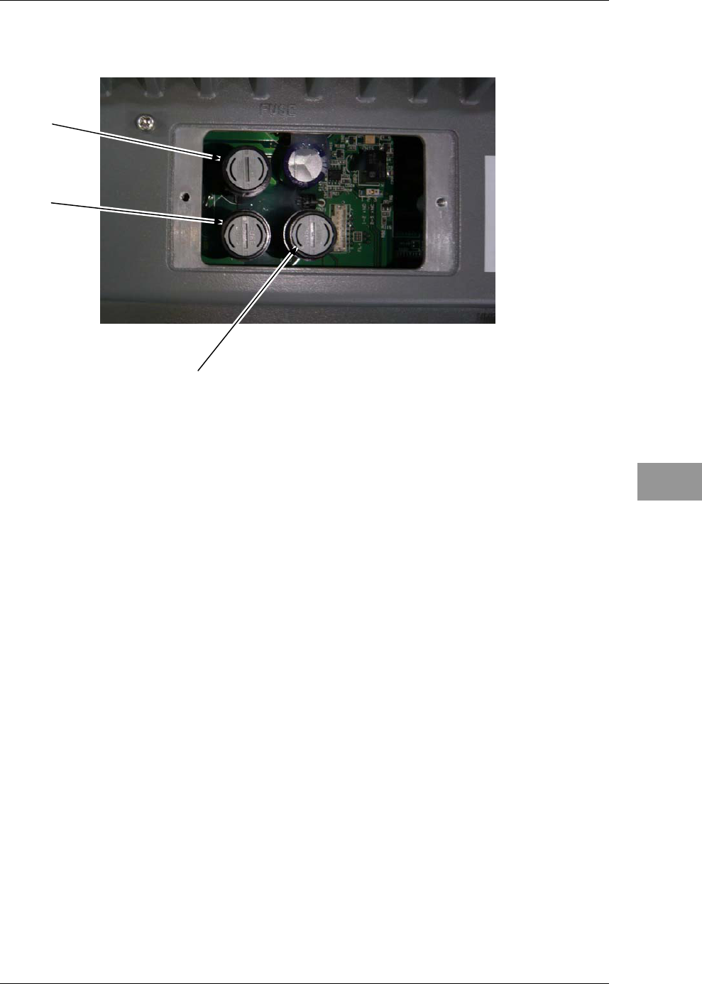
Fuse Locations
Fuse locations are shown below.
F3
F1
F2
Chapter 4
MAINTENANCE
4.6
TROUBLE SHOOTING
4-30
4.6 TROUBLE SHOOTING
As this radar equipment includes complicated circuits, it is necessary to request a
specialist engineer for repair or instructions for remedy if any circuit is defective.
There are also troubles by the following causes, which should be referred to in checking
or repair work.
zPoor Contact in Terminal Board of Inter-Unit Cables
yPoor contact in terminal board
yThe cable end is not fully connected, that it, contacted with earthed another
terminal.
yDisconnected cable wire
zPoor Contact of Connector within Unit
Reference:
This radar equipment is provided with standard included accessories shown in Table 4.6-1.
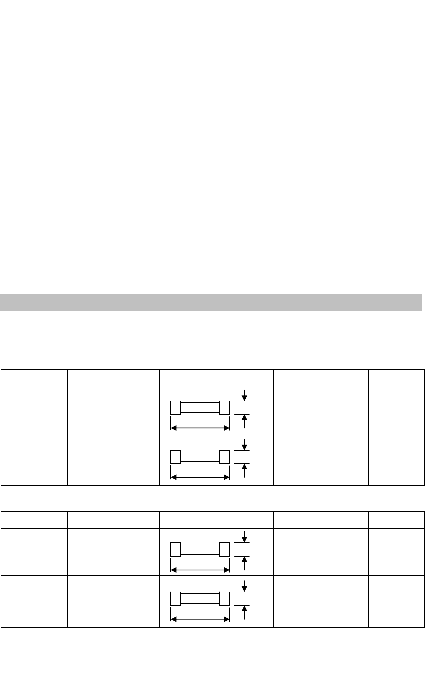
4.6.1 INCLUDED ACCESSORIES
Table 4.6-1 Included accessories
7ZXRD0012 : Scanner NKE-2042 (4kW)
Name/Type Parts No. Code Shape (mm) Quantity Location Application
Fuse
ST4-6.3AN1 F2 5ZFCA00051 4Inside
processing unit
(DC12V)
For the
modulator
Fuse
ST4-3.15AN1 F2 5ZFCA00047 4 Inside
processing unit
(DC24V)
For the
modulator
7ZXRD0012 : Scanner NKE-2043 (4kW)
Name/Type Parts No. Code Shape (mm) Quantity Location Application
Fuse
ST4-6.3AN1 F2 5ZFCA00051 4Inside
processing unit
(DC12V)
For the
compound
modulator
Fuse
ST4-3.15AN1 F2 5ZFCA00047 4 Inside
processing unit
(DC24V)
For the
compound
modulator
31.8
6.35
31.8
6.35
31.8
6.35
31.8
6.35
Chapter 4
MAINTENANCE
4.6
TROUBLE SHOOTING
4-31
4
INSTRUCTION MANUAL
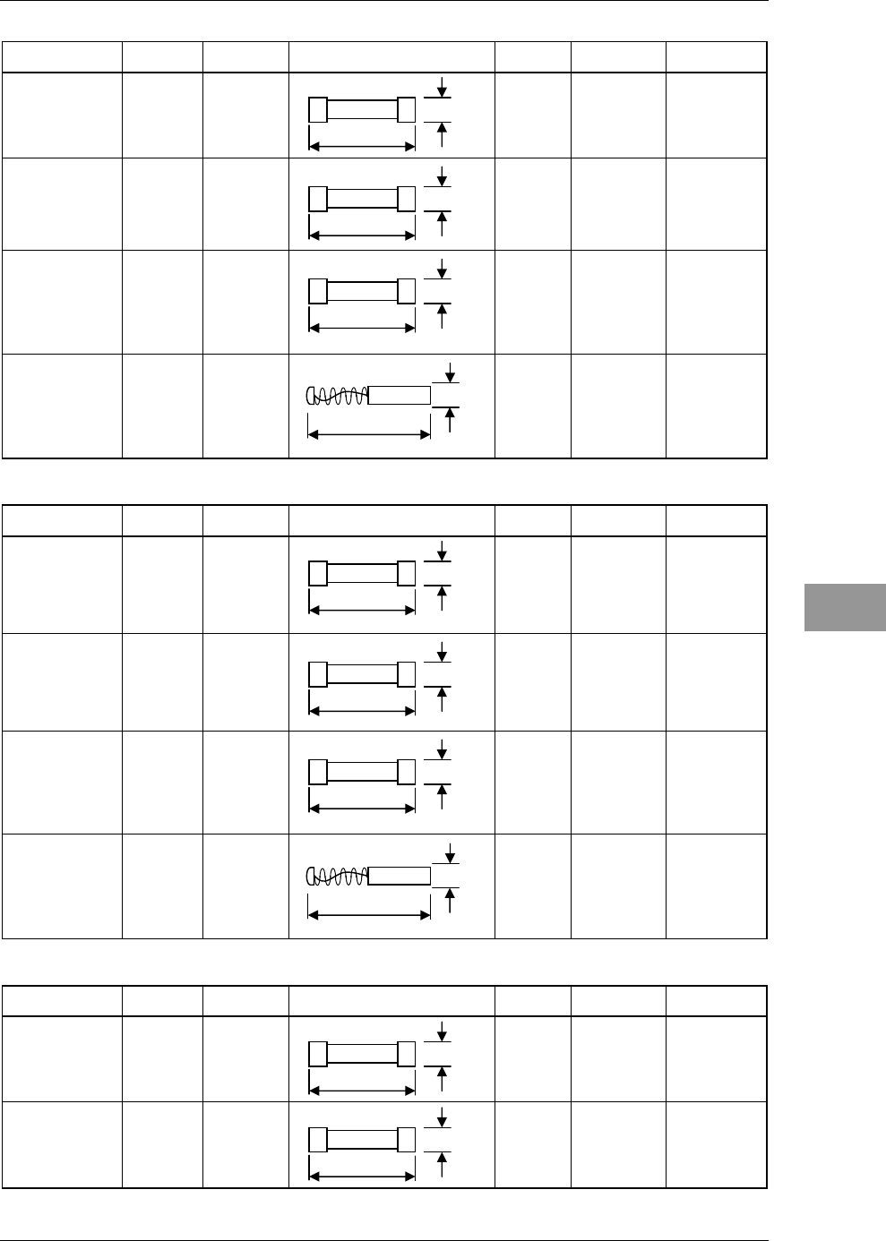
7ZXRD0013 : Scanner NKE-2062/HS (6kW)
Name/Type Parts No. Code Shape (mm) Quantity Location Application
Fuse
ST4-6.3AN1 F2 5ZFCA00051 4Inside
processing unit
NKE-2062
(DC12V)
For the
modulator
Fuse
ST4-3.15AN1 F2 5ZFCA00047 4 Inside
processing unit
NKE-2062/HS
(DC24V)
For the
modulator
Fuse
ST4-5AN1 F3 5ZFCA00050 4 Inside
processing unit
NKE-2062/HS
For the scanner
motor
Carbon brush
54531-01 – BRXP05247 2 Scanner For the scanner
motor
7ZXRD0013 : Scanner NKE-2063/HS (6kW)
Name/Type Parts No. Code Shape (mm) Quantity Location Application
Fuse
ST4-6.3AN1 F2 5ZFCA00051 4 Inside
processing unit
NKE-2063
(DC12V)
For the
compound
modulator
Fuse
ST4-3.15AN1 F2 5ZFCA00047 4 Inside
processing unit
NKE-2063/HS
(DC24V)
For the
compound
modulator
Fuse
ST4-5AN1 F3 5ZFCA00050 4 Inside
processing unit
NKE-2063/HS
For the scanner
motor
Carbon brush
54531-01 – BRXP05247 2 Scanner For the scanner
motor
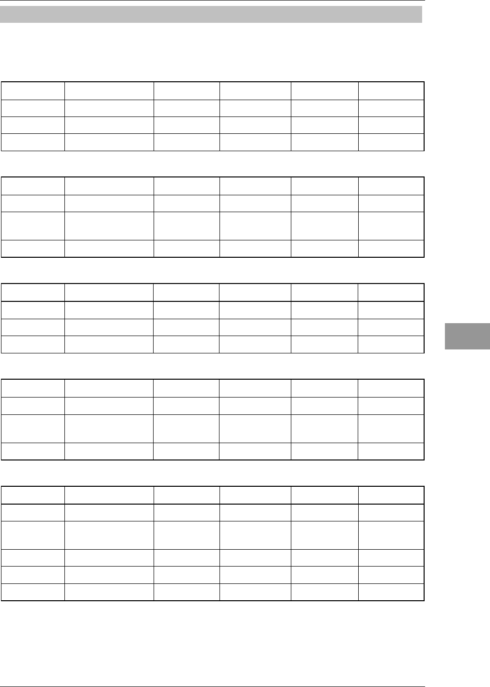
7ZXRD0026 : Scanner NKE-2103-4/4HS/6/6HS (10kW)
Name/Type Parts No. Code Shape (mm) Quantity Location Application
Fuse
ST4-5AN1 F2 5ZFCA00050 4 Inside
processing unit
For the
modulator
Fuse
ST6-10AN1 F3 5ZFCA00053 4 Inside
processing unit
For the power
supply to motor
32.0
8.0
31.8
6.35
31.8
6.35
31.8
6.35
31.8
6.35
31.8
6.35
31.8
6.35
31.8
6.35
31.8
6.35
32.0
8.0

Chapter 4
MAINTENANCE
4.6
TROUBLE SHOOTING
4-32
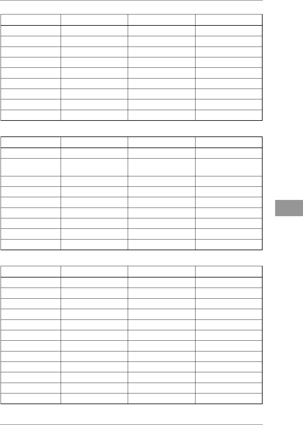
7ZXRD0028 : Display unit NDC-2182
Name/Type Parts No. Code Shape (mm) Spare Location Application
Connector
LTWBD-06BFFA-
LL7001
P3 5JCDX00032 1
Inside
processing
unit
Mainly for GPS
connection
Connector
LTWBD-08BFFA-
LL7001
P5 5JCDX00034 1
Inside
processing
unit
Mainly for connecting
course equipment such
as a GPS compass
Connector
LTWBD-07BFFA-
LL7001
P6 5JCD00033 1
Inside
processing
unit
For AIS connection
For connecting other
external devices when
the AIS is not used
For acquiring 2-axis
logs, current data, and
wind direction data
44.0
18.0
44.0
18.0
44.0
18.0
Chapter 4
MAINTENANCE
4.6
TROUBLE SHOOTING
4-33
4
INSTRUCTION MANUAL
4.6.2 SPECIAL PARTS
Table 4.6-2 Special Parts
JMA-3314
Parts No. Name Type Code Manufacturer Location
V201 Magnetron MSF1421B 5VMAA00049 NJRC Scanner
A101 Circulator FCX68 6AJRD00001 Toshiba Scanner
A102 Diode Limiter NJS6930 5EZAA00024 NJRC Scanner
JMA-3334
Parts No. Name Type Code Manufacturer Location
V101 Magnetron MSF1421B 5VMAA00092 NJRC Scanner
A101 Circulator FCX68R 5AJIX00027
Orient
Microwave Scanner
A102 Diode Limiter NJS6930 5ATBT00006 NJRC Scanner
JMA-3316/HS
Parts No. Name Type Code Manufacturer Location
V101 Magnetron MSF1422B 5VMAA00068 NJRC Scanner
A101 Circulator FCX68 6AJRD00001 Toshiba Scanner
A102 Diode Limiter NJS6930 5EZAA00024 NJRC Scanner
JMA-3336/HS
Parts No. Name Type Code Manufacturer Location
V101 Magnetron MSF1422B 5VMAA00090 NJRC Scanner
A101 Circulator FCX68R 5AJIX00027
Orient
Microwave Scanner
A102 Diode Limiter NJS6930 5ATBT00006 NJRC Scanner
JMA-3340-4/4HS/6/6HS
Parts No. Name Type Code Manufacturer Location
V101 Magnetron MAF1565N 5VMAA00102 NJRC Scanner
A101/A102 Circulator FCX68R 5AJIX00027 Orient
Microwave Scanner
A103 Dummy NJC4002 5ANDF00001 NJRC Scanner
A104 Filter NJC9952 5AWAX00002 NJRC Scanner
A301 Diode Limiter NJS6930 5ATBT00006 NJRC Scanner

Chapter 4
MAINTENANCE
4.6
TROUBLE SHOOTING
4-34
4.6.3 CIRCUIT BLOCK TO BE REPAIRED
Table 4.6-3 Circuit Block to be Repaired
JMA-3314
Location Circuit Block Type Remarks
Scanner Motor unit 7BDRD0023*
Scanner Modulation circuit CME-322
Scanner Receiver CAE-475
Display Unit Processing circuit CDC-1346BR
Display Unit I/F circuit CMH-2235
Display Unit I/F circuit CQC-1262
Display Unit Operation circuit CCK-991
Display Unit Operation circuit CCK-1017
Display Unit Fuse MF60NR 250V 10 F1
"*" means revision, such as A, B and so on.
JMA-3334
Location Circuit Block Type Remarks
Scanner Motor 7BDRD0052*
Scanner Compound Modulator
Circuit CME-385
Scanner Receiver Unit NRG-239 Including CAE-548
Display Unit Processing circuit CDC-1346BR
Display Unit I/F circuit CMH-2235
Display Unit I/F circuit CQC-1262
Display Unit Operation circuit CCK-991
Display Unit Operation circuit CCK-1017
Display Unit Fuse MF60NR 250V 10 F1
"*" means revision, such as A, B and so on.
Chapter 4
MAINTENANCE
4.6
TROUBLE SHOOTING
4-35
4
INSTRUCTION MANUAL
JMA-3316/HS
Location Circuit Block Type Remarks
Scanner Motor with gear CBP-169 DC brushless motor
Scanner Modulator CME-339 Excluding Magnetron
Scanner Receiver NRG-226 Including CAE-475-1
Display Unit Processing circuit CDC-1346BR
Display Unit I/F circuit CMH-2235
Display Unit I/F circuit CQC-1262
Display Unit Operation circuit CCK-991
Display Unit Operation circuit CCK-1017
Display Unit Fuse MF60NR 250V 10 F1
JMA-3336/HS
Location Circuit Block Type Remarks
Scanner Motor CBP-218 DC brushless motor
Scanner Compound Modulator
Circuit CME-386 Excluding Magnetron
Scanner Receiver Unit NRG-239 Including CAE-548
Display Unit Processing circuit CDC-1346BR
Display Unit I/F circuit CMH-2235
Display Unit I/F circuit CQC-1262
Display Unit Operation circuit CCK-991
Display Unit Operation circuit CCK-1017
Display Unit Fuse MF60NR 250V 10 F1
JMA-3340-4/4HS/6/6HS
Location Circuit Block Type Remarks
Scanner Motor with gear 7BDRD0048* DC brushless motor
Scanner Modulation circuit CME-363 Excluding Magnetron
Scanner Receiver NRG-610 Including CAE-529-1
Scanner Power supply circuit CBD-1783
Scanner Encoder CHT-71A
Scanner Motor control power circuit CBD-1779
Display Unit Processing circuit CDC-1346BR
Display Unit I/F circuit CMH-2235
Display Unit I/F circuit CQC-1262
Display Unit Operation circuit CCK-991
Display Unit Operation circuit CCK-1017
Display Unit Fuse MF60NR 250V 10 F1
"*" means revision, such as A, B and so on.

Chapter 4
MAINTENANCE
4.6
TROUBLE SHOOTING
4-36

Chapter 5
AFTER-SALES SERVICE
5.1
KEEPING PERIOD OF MAINTENANCE PARTS
5-1
5
INSTRUCTION MANUAL
Chapter 5
AFTER-SALES SERVICE
5.1 KEEPING PERIOD OF MAINTENANCE PARTS
Keeping period of maintenance parts is ten years from the production is discontinued.
5.2 WHEN YOU REQUEST FOR REPAIR
If you suppose the product may be out of order, read the description in "4.5 FAULT
FINDING" and "4.6 TROUBLE SHOOTING", and check the suspected point again.
If it is still out of order, you are recommended to stop operation of the equipment and
consult with the dealer from whom you purchased the product, or our branch office in
your country or district, the sales department in our main office in Tokyo.
z Repair within the Warranty Period If any failure occurs in the product during
its normal operation in accordance with the instruction manual, the dealer or JRC
will repair free of charge. In case that any failure is caused due to misuse, faulty
operation, negligence or force major such as natural disaster and fire, the product
will be repaired with charges.
z Repair after the Warranty Period If any defective function of the product is
recoverable by repair, the repair of it will be made at your own charge upon your
request.
z Necessary Information for Repair
ۼ Product name, model, manufacturing date and serial number
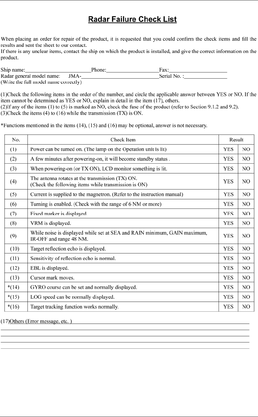
ۼ Trouble conditions (as detailed as possible. Refer to page 5-2 "■ Radar Failure
Check List".)
ۼ Name of company/organization, address and telephone number
5.3 RECOMMENDED MAINTENANCE
The performance of the product may deteriorate due to the secular change of the parts
used in it, though such deterioration depends upon the conditions of operation.
So checkup and maintenance is recommendable for the product in addition to your daily
care.
For maintenance, consult with the near-by dealer or our sales department.
Such maintenance will be made with charges.
For further details of after-sale service, contact the JRC Offices.
Chapter 5
AFTER-SALES SERVICE
5.3
RECOMMENDED MAINTENANCE
5-2
Radar Failure Check List

Chapter 6
DISPOSAL
6.1
DISPOSAL OF THE UNIT
6-1
6
INSTRUCTION MANUAL
Chapter 6 DISPOSAL
6.1 DISPOSAL OF THE UNIT
When disposing of this unit, be sure to follow the local laws and regulations for the place
of disposal.
Chapter 6
DISPOSAL
6.2
DISPOSAL OF USED MAGNETRON
6-2
6.2 DISPOSAL OF USED MAGNETRON
Magnetron is used in the Scanner (NKE-2103).
zWhen the magnetron is replaced with a new one, return the used magnetron to our
dealer or business office.
For detail, consult with our dealer or business office.
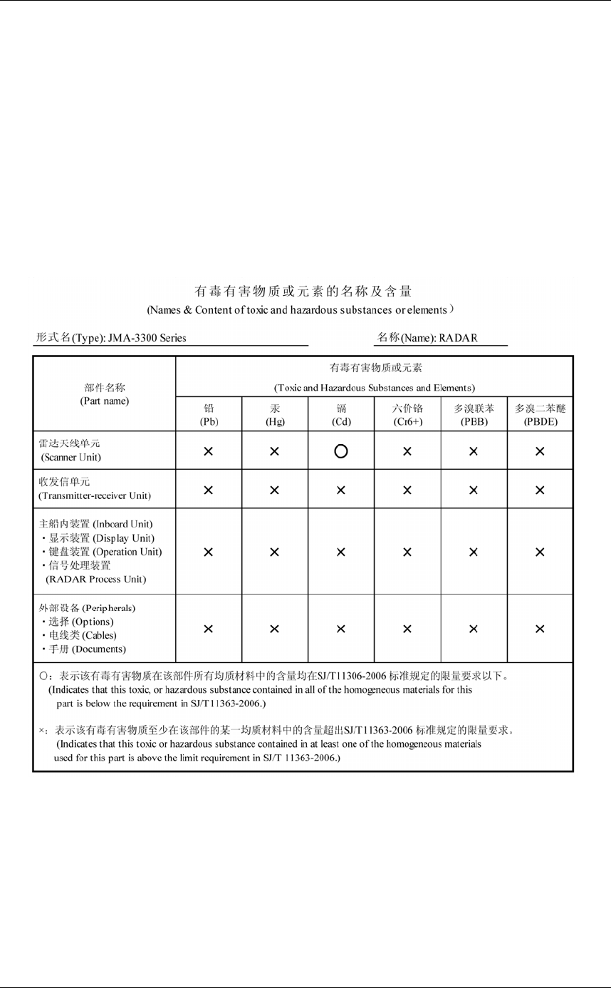
6.3 CHINA RoHS

Chapter 7
SPECIFICATIONS
7.1
GENERAL SPECIFICATIONS
7-1
7
INSTRUCTION MANUAL
Chapter 7 SPECIFICATIONS
7.1 GENERAL SPECIFICATIONS
(1) Class of Emission P0N
(2) Display Color Raster Scan
(3) Display capability VGA
(4) Screen 10.4-inch Color LCD
Effective diameter of radar echo, more than 150 mm
(5) Range Scale 0.125, 0.25, 0.5, 0.75, 1.5, 3, 6, 12, 24, 48, 72 NM
User can add 0.0625, 1, 2, 4, 8, 16, 32 or 64 NM.
* Off Center is not available at 64, 72NM.
(6) Range Resolution Less than 30m
(7) Minimum Detective Range Less than 40m
(8) Range Accuracy Less than 1% of the maximum distance of the range scale
in use or less than 15m whichever is larger
(9) Bearing Accuracy Less than 1°
(10) Bearing Indication Head-up, North-up, Course-up
(11) Ambient Condition
Standards IEC60945 Ed.4.0
Temperature
Scanner Operation: -25 to +55°C / Storage: -25 to +70°C
Other Unit except Scanner
Operation: -15 to +55°C
Relative Humidity
Entire Unit +40°C, 93%
Vibration
Entire Unit 2 to 13.2 Hz, amplitude±1mm
13.2 to 100 Hz 0.7 G
Velocity of the wind 51.5m/s (100kn)
Waterproof/dustproof Scanner IP26
Display Unit IP55 (front panel)
(12) Power Supply Input DC+24V (All models, cable length of 30m or less)
DC+12V
(4 kW/6 kW models, cable length of 20m or less)

Chapter 7
SPECIFICATIONS
7.1
GENERAL SPECIFICATIONS
7-2
(13) Power Consumption In calm wind:
Approx. 60W (NKE-2042)
Approx. 60W (NKE-2043)
Approx. 85W (NKE-2062)
Approx. 85W (NKE-2063)
Approx. 85W (NKE-2062HS)
Approx. 85W (NKE-2063HS)
Approx. 100W (NKE-2103-4)
Approx. 100W (NKE-2103-4HS)
Approx. 100W (NKE-2103-6)
Approx. 100W (NKE-2103-6HS)
Maximum (Velocity of the wind: 100 kn):
Approx. 60W (NKE-2042)
Approx. 60W (NKE-2043)
Approx. 230W (NKE-2062)
Approx. 180W (NKE-2063)
Approx. 230W (NKE-2062HS)
Approx. 230W (NKE-2063HS)
Approx. 360W (NKE-2103-4)
Approx. 360W (NKE-2103-4HS)
Approx. 360W (NKE-2103-6)
Approx. 360W (NKE-2103-6HS)
(14) Range of power supply voltage fluctuation
+10.8 to 41.6 VDC (Display Unit) (4kW/6kW)
+21.6 to 31.2 VDC (Display Unit)
(6kWHS/10kW/10kWHS)
(15) Pre-heating Time Approx. Within 1min30sec
(16) Scanner Refer to Scanner Specifications
(17) Display unit Refer to Display Unit Specifications
(18) Inter-Unit Cables Using common scanner connecting cable CFQ-6912-**
Maximum cable length: 30 m

Chapter 7
SPECIFICATIONS
7.2
SCANNER
7-3
7
INSTRUCTION MANUAL
7.2 SCANNER
7.2.1 NKE-2042
(1) Dimensions Height 275mmDiameter of radome 620mm
(2) Mass Approx. 10.5kg
(3) Polarization Horizontal Polarization
(4) Directional Characteristic
Horizontal Beam Width (-3dB):
2°
Vertical Beam Width (-3dB):
25°
Sidelobe Level: -21dB or less (less than ±10° from the main lobe)
(5) Rotation Approx. 27rpm (NKE-2042)
(6) Peak Power 4 kW
(7) Transmitting Frequency 9410 r30MHz
(8) Transmitting Tube Magnetron [MSF1421B]
(9) Pulse width/Repetition Frequency (Bandwidth)
SP: 0.08Ps/2250 Hz
MP1: 0.25Ps/1700 Hz, MP2: 0.5Ps/1200 Hz
LP1: 1.0Ps/650 Hz
0.125NM 0.08Ps/2250Hz (SP)
0.25NM 0.08Ps/2250Hz (SP)
0.5NM 0.08Ps/2250Hz (SP) 0.25Ps/1700Hz (MP1)
0.75NM 0.08Ps/2250Hz (SP) 0.25Ps/1700Hz (MP1)
1.5NM 0.08Ps/2250Hz (SP) 0.25Ps/1700Hz (MP1)
3NM 0.25Ps/1700Hz (MP1) 0.5Ps/1200Hz (MP2)
6NM 0.5s/1200Hz (MP2) 1.0Ps/650Hz (LP1)
12NM 1.0s/650Hz (LP1)
24NM 1.0s/650Hz (LP1)
48NM 1.0s/650Hz (LP1)
(10) Duplexer Circulator + Diode Limiter
(11) Front End Module MIC
(12) Intermediate Frequency Amplifier
Intermediate Frequency: 60MHz
Band Width: 20MHz (0.08Ps)
6MHz (0.25Ps, 0.5Ps)
3MHz (1.0Ps)
Gain: More than 90dB
Amplifying Characteristics: Logarithmic Amplifier
(13) Overall Noise Figure 6dB (Average)

Chapter 7
SPECIFICATIONS
7.2
SCANNER
7-4
7.2.2 NKE-2043
(1) Dimensions Height 275mmDiameter of radome 620mm
(2) Mass Approx. 10kg
(3) Polarization Horizontal Polarization
(4) Directional Characteristic
Horizontal Beam Width (-3dB):
4°
Vertical Beam Width (-3dB):
25°
Sidelobe Level: -21dB or less (less than ±10° from the main lobe)
(5) Rotation Approx. 27rpm (NKE-2043)
(16/20/24/27/30/36/42/48rpm can be set)
(6) Peak Power 4 kW
(7) Transmitting Frequency 9410 r30MHz
(8) Transmitting Tube Magnetron [MSF1421B]
(9) Pulse width/Repetition Frequency (Bandwidth)
SP1: 0.08s/4000Hz, SP2: 0.08s/2250Hz, SP3: 0.13s/1700Hz
MP1: 0.25s/1700Hz, MP2: 0.5s/1200Hz
LP1: 0.8s/750Hz, LP2: 1.0s/650Hz
0.125NM 0.08Ps/4000Hz (SP1)
0.25NM 0.08Ps/4000Hz (SP1)
0.5NM 0.08Ps/4000Hz (SP1) 0.25Ps/1700Hz (MP1)
0.75NM 0.08Ps/2250Hz (SP2) 0.25Ps/1700Hz (MP1)
1.5NM 0.08Ps/2250Hz (SP2) 0.25Ps/1700Hz (MP1) 0.5s/1200Hz (MP2)
3NM 0.13Ps/1700Hz (SP3) 0.25Ps/1700Hz (MP1) 0.5s/1200Hz (MP2)
6NM 0.5s/1200Hz (MP2) 0.8Ps/750Hz (LP1) 1.0s/650Hz (LP2)
12NM 0.5s/1200Hz (MP2) 0.8s/750Hz (LP1) 1.0s/650Hz (LP2)
24NM 1.0s/650Hz (LP2)
48NM 1.0s/650Hz (LP2)
72NM 1.0s/650Hz (LP2)
(10) Duplexer Circulator + Diode Limiter
(11) Front End Module MIC
(12) Intermediate Frequency Amplifier
Intermediate Frequency: 60MHz
Band Width: 20MHz (0.08s, 0.13s)
6MHz (0.25Ps)
3MHz (0.5s, 0.8s, 1.0s)
Gain: More than 90dB
Amplifying Characteristics: Logarithmic Amplifier
(13) Overall Noise Figure 6dB (Average)

Chapter 7
SPECIFICATIONS
7.2
SCANNER
7-5
7
INSTRUCTION MANUAL
7.2.3 NKE-2062/HS
(1) Dimensions Height 432mmSwing Circle 1220mm
(2) Mass Approx. 24kg
(3) Polarization Horizontal Polarization
(4) Directional Characteristic
Horizontal Beam Width (-3dB):
2°
Vertical Beam Width (-3dB):
30°
Sidelobe Level: -23dB or less (less than ±10° from the main lobe)
-26dB or less (±10° or more from the main lobe)
(5) Rotation Approx. 27rpm (NKE-2062)
Approx. 48rpm (NKE-2062HS)
(6) Peak Power 6 kW
(7) Transmitting Frequency 9410 r30MHz
(8) Transmitting Tube Magnetron [MSF1422B]
(9) Pulse width/Repetition Frequency (Bandwidth)
SP: 0.08Ps/2250 Hz
MP1: 0.25Ps/1700 Hz, MP2: 0.5Ps/1200 Hz
LP1: 1.0Ps/650 Hz
0.125NM 0.08Ps/2250Hz (SP)
0.25NM 0.08Ps/2250Hz (SP)
0.5NM 0.08Ps/2250Hz (SP) 0.25Ps/1700Hz (MP1)
0.75NM 0.08Ps/2250Hz (SP) 0.25Ps/1700Hz (MP1)
1.5NM 0.08Ps/2250Hz (SP) 0.25Ps/1700Hz (MP1)
3NM 0.25Ps/1700Hz (MP1) 0.5Ps/1200Hz (MP2)
6NM 0.5Ps/1200Hz (MP2) 1.0s/650Hz (LP1)
12NM 1.0Ps/650Hz (LP1)
24NM 1.0Ps/650Hz (LP1)
48NM 1.0Ps/650Hz (LP1)
72NM 1.0Ps/650Hz (LP1)
(10) Duplexer Circulator + Diode Limiter
(11) Front End Module MIC
(12) Intermediate Frequency Amplifier
Intermediate Frequency: 60MHz
Band Width: 20MHz (0.08Ps)
6MHz (0.25Ps, 0.5Ps)
3MHz (1.0Ps)
Gain: More than 90dB
Amplifying Characteristics: Logarithmic Amplifier

Chapter 7
SPECIFICATIONS
7.2
SCANNER
7-6
(13) Overall Noise Figure 6dB (Average)
(14) Tune AUTO/MANUAL

Chapter 7
SPECIFICATIONS
7.2
SCANNER
7-7
7
INSTRUCTION MANUAL
7.2.4 NKE-2063/HS
(1) Dimensions Height 419.5mmSwing Circle 1220mm
(2) Mass Approx. 21kg
(3) Polarization Horizontal Polarization
(4) Directional Characteristic
Horizontal Beam Width (-3dB):
2°
Vertical Beam Width (-3dB):
30°
Sidelobe Level: -23dB or less (less than ±10° from the main lobe)
-26dB or less (±10° or more from the main lobe)
(5) Rotation Approx. 27rpm (NKE-2063)
(16/17.4/19/20.6/22.2/23.8/25.4/27rpm can be set)
Approx. 48rpm
(27/36/48rpm can be set)
(6) Peak Power 6 kW
(7) Transmitting Frequency 9410 r30MHz
(8) Transmitting Tube Magnetron [MSF1422B]
(9) Pulse width/Repetition Frequency (Bandwidth)
SP1: 0.08Ps/4000Hz, SP2: 0.08Ps/2250Hz, SP3: 0.13Ps/1700Hz
MP1: 0.25Ps/1700 Hz, MP2: 0.5Ps/1200 Hz
LP1: 0.8s/750Hz, LP2: 1.0s/650Hz
0.125NM 0.08Ps/4000Hz (SP1)
0.25NM 0.08Ps/4000Hz (SP1)
0.5NM 0.08Ps/4000Hz (SP1) 0.25Ps/1700Hz (MP1)
0.75NM 0.08Ps/2250Hz (SP2) 0.25Ps/1700Hz (MP1)
1.5NM 0.08Ps/2250Hz (SP2) 0.25Ps/1700Hz (MP1) 0.5s/1200Hz (MP2)
3NM 0.13Ps/1700Hz (SP3) 0.25Ps/1700Hz (MP1) 0.5s/1200Hz (MP2)
6NM 0.5Ps/1200Hz (MP2) 0.8s/750Hz (LP1) 1.0s/650Hz (LP2)
12NM 0.5Ps/1200Hz (MP2) 0.8s/750Hz (LP1) 1.0s/650Hz (LP2)
24NM 1.0Ps/650Hz (LP2)
48NM 1.0Ps/650Hz (LP2)
72NM 1.0Ps/650Hz (LP2)
(10) Duplexer Circulator + Diode Limiter
(11) Front End Module MIC

Chapter 7
SPECIFICATIONS
7.2
SCANNER
7-8
(12) Intermediate Frequency Amplifier
Intermediate Frequency: 60MHz
Band Width: 20MHz (0.08s, 0.13s)
6MHz (0.25Ps)
3MHz (0.5s, 0.8s, 1.0s)
Gain: More than 90dB
Amplifying Characteristics: Logarithmic Amplifier
(13) Overall Noise Figure 6dB (Average)
(14) Tune AUTO/MANUAL

Chapter 7
SPECIFICATIONS
7.2
SCANNER
7-9
7
INSTRUCTION MANUAL
7.2.5 NKE-2103-4/6/4HS/6HS
(1) Dimensions Height: approx. 458 mm
Swing Circle: approx. 1,285mm (4ft)
Height: approx. 458 mm
Swing Circle: approx. 1910 mm (6ft)
(2) Mass Approx. 38 kg (4ft)
Approx. 40 kg (6ft)
(3) Polarization Horizontal Polarization
(4) Directional Characteristic
Horizontal Beam Width (-3dB)
1.8° (4ft)
1.2° (6ft)
Vertical Beam Width (-3dB)
20° (4ft/6ft)
Sidelobe Level –26 dB or less (less than ±10° from the main lobe)
(4ft/6ft)
–30 dB or less (±10° or more from the main lobe)
(4ft/6ft)
(5) Rotation 27rpm (NKE-2103-4/6)
48rpm (NKE-2103-4HS/6HS)
(6) Transmitting Frequency 9410 ±30 MHz
(7) Peak Power 10 kW r50%
(8) Transmitting Tube Magnetron [MAF1565N]
(9) Transmitting Pulse Width/Repetition Frequency (Bandwidth)
SP: 0.08Ps/2250 Hz
MP1: 0.25Ps/1700 Hz, MP2: 0.5Ps/1200 Hz
LP1: 0.8Ps/750 Hz, LP2: 1.0Ps/650 Hz
0.125NM 0.08Ps/2250Hz (SP)
0.25NM 0.08Ps/2250Hz (SP)
0.5NM 0.08Ps/2250Hz (SP) 0.25Ps/1700Hz (MP1)
0.75NM 0.08Ps/2250Hz (SP) 0.25Ps/1700Hz (MP1)
1.5NM 0.08Ps/2250Hz (SP) 0.25Ps/1700Hz (MP1) 0.5s/1200Hz (MP2)
3NM 0.25Ps/1700Hz (MP1) 0.5Ps/1200Hz (MP2) 0.8s/750Hz (LP1)
6NM 0.5Ps/1200Hz (MP2) 0.8Ps/750Hz (LP1) 1.0s/650Hz (LP2)
12NM 0.5Ps/1200Hz (MP2) 0.8Ps/750Hz (LP1) 1.0s/650Hz (LP2)
24NM 1.0Ps/650Hz (LP2)
48NM 1.0Ps/650Hz (LP2)
72NM 1.0Ps/650Hz (LP2)
(10) Duplexer Circulator + Diode Limiter

Chapter 7
SPECIFICATIONS
7.2
SCANNER
7-10
(11) Front End Module MIC
(12) Intermediate Frequency Amplifier
Intermediate Frequency: 60MHz
Band Width: 20MHz (0.08Ps)
6MHz (0.25Ps, 0.5Ps)
3MHz (0.8Ps, 1.0Ps)
Gain: More than 90dB
Amplifying Characteristics: Logarithmic Amplifier
(13) Overall Noise Figure 7.5dB (Average)
(14) Tune Method AUTO/MANUAL

Chapter 7
SPECIFICATIONS
7.3
DISPLAY UNIT
7-11
7
INSTRUCTION MANUAL
7.3 DISPLAY UNIT
7.3.1 INTEGRATED DISPLAY UNIT (NCD-2182)
(1) Structure Desk Top Integrated Type (LCD Monitor Unit/Keyboard
Unit/Processor Unit Integrated Structure)
Vertical installation only desk top integrated type
(2) Dimensions
Desktop installation Height 310mm × Width 328mm × Depth 130.5mm
Flush-mounting Height 290mm × Width 297mm × Depth 120mm
(3) Mass Approx. 5kg
(4) Tune Method MANUAL/AUTO (Bar-graph indication)
(5) STC (SEA) MANUAL/AUTO
(6) FTC (RAIN) MANUAL/AUTO
(7) Radar Interference Rejection
Built-in (The effect can be adjusted by three stages.)
(8) Bearing Marker 360° in 5° digit
(9) Heading Line Electronic
(10) Off Center Within 66% of the radius of PPI
(Not available at the maximum range)
Transition of the radar trails is possible during Off Center
mode.
(11) True Motion Unit Built-in (Not available at the maximum range)
(12) True Motion Reset Position
66% of radius of any range
(13) Radar trail indication True motion mode: Only true motion trails
Relative motion mode: Only relative motion trails
Trail time length: 15 sec to 15 min/Continuous
30 sec to 30 min/Continuous
1 min to 1 hr/Continuous
30 min to 12 hr/Continuous
Arbitrary trail time length can be displayed at any time.
Possible to display time series trail and continuous trail
by color classification.
Not possible to select true motion trails or relative motion
trails.
* When switching to true/relative trails, the radar trails
are cleared.
Transition of the trails is possible during Off Center
mode (Relative motion). (Scroll)
When the bearing mode is switched (RM (T), TM)

Chapter 7
SPECIFICATIONS
7.3
DISPLAY UNIT
7-12
When the motion is switched (between RM (T) and TM),
true motion trails is transition.
* When switching to true/relative trails, the radar trails
are cleared.
(14) Variety of Pulse width SP/MP1/MP2/LP1 (NKE-2042)
SP/MP1/MP2/LP1 (NKE-2062)
SP/MP1/MP2/LP1/LP2 (NKE-2103)
(15) Target enhance 3 stages
(16) Plotting Line/200 marks/3 colors for own ship’s tracks, line types
selectable
(17) Display color
Radar echo 16 stages, 5 colors
(Yellow, Green, Orange, Purple, Red, Colored)
Radar trails 16 stages
3 colors for time trails (Green, White, Light Blue)
3 colors for continuous trails
(Green, White, Light Blue)
Background within PPI 3 colors (Black, Blue, Navy Blue)
Characters 5 colors (White, Orange, Green, Black, Red)
Cursor 4 colors (Cyan, Orange, Green, White)
AIS/vector 3 colors (Cyan, Green, White)
EBL/VRM 4 colors (Light Blue, Orange, Green, White)
(18) Simulator Built-in simulator
(19) Full screen Full screen (displayed without PPI mask)
(20) Multiple languages Japanese, English, French, German, Spanish, Italian,
Portuguese, Norwegian
(21) LL / TD conversion Built-in
(22) Navigation information during STBY
Built-in
(23) Land mile display Range, scale, VRM
(24) Barge display Displays the own ship and a barge.
(25) AIS information display (MMSI, ship name) List display, Retrieved Vessel,
WPT setting

Chapter 7
SPECIFICATIONS
7.3
DISPLAY UNIT
7-13
7
INSTRUCTION MANUAL
7.3.2 OPERATION PANEL
(1) Structure Integrated on the display unit
(2) Controls GAIN
SEA
RAIN
MULTI
Cursor keys
(3) Keys
STBY Stops transmission (Turns off the equipment if
simultaneously pressed with "TX/PRF")
TX/PRF Starts transmission (Turns off the equipment if
simultaneously pressed with "STBY")
Changes PRF during transmission. Clears SHM when
held down.
RANGE+ Increases the distance range.
RANGE- Decreases the distance range.
FUNC Switches the function.
BRILL Adjusts LCD brightness
ENT Enter key (Selects menu items, etc)
CLEAR Cancels operations
MENU Opens/closes the menu screen
Soft key 1 Soft key 1
Soft key 2 Soft key 2
Soft key 3 Soft key 3
Soft key 4 Soft key 4
7.3.3 AIS FUNCTION
(1) Screen
Number of targets Up to 50 targets (stores up to 500 ship static data)
Target information Displays MMSI, call sign, ship name, COG, SOG,
CPA, TCPA, direction, distance, latitude, longitude,
status, etc.
Filters Distance only
Active targets Not available
Dangerous ship targets No CPA/TCPA decision
(2) Operation Built-in

Chapter 7
SPECIFICATIONS
7.3
DISPLAY UNIT
7-14
7.3.4 TT FUNCTION
(1) Acquisition MANUAL/AUTO
(by automatic acquisition/activation zone)
(2) Tracking 10 targets (Automatic tracking)
(3) Display
Tracking data 1 ship (AIS or TT)
Maximum tracking range 20 NM
This varies depending on the range.
Target information Displays items selected from true bearing, distance,
true course, true speed, CPA, TCPA.
Display of Vectors True/Relative
Dangerous ship targets Decision by CPA/TCPA
(4) Operation Built-in

Chapter 7
SPECIFICATIONS
7.4
INPUT/OUTPUT SIGNAL
7-15
7
INSTRUCTION MANUAL
7.4 INPUT/OUTPUT SIGNAL
7.4.1 INPUT ENABLE SIGNAL
(1) Navigation equipment IEC61162-1/2
Longitude/Latitude: GGA>RMC>GNS>GLL
COG/SOG: RMC>VTG
Log speed: VBW>VHW, NSK data
Bearing: THS>HDT>HDG>HDM
Depth: DPT>DBT
Water temperature: MTW
Rate of Turn: ROT
Rudder: RSA
AIS: VDM, VDO, ALR
Direction of wind, velocity of wind: MWV>VWT, VWR
(2) Bearing signal GYRO-SYNC:
360X, 180X, 90X, 36X
(Require optional NSK unit NCT-4106A)
GYRO-STEP:
360X, 180X, 90X, 36X
(Require optional NSK unit NCT-4106A)
JRC-NSK format (JLR-10/20/30)
IEC61162 4800bps/38400bps:
THS>HDT>HDG>HDM
(3) Speed signal LOG-SYNC: 360X, 180X, 90X, 30X
(Require optional NSK unit NCT-4106A)
LOG-PULSE: 800, 400, 200, 100
(Require optional NSK unit NCT-4106A)
IEC61162 4800bps: VBW, VHW
7.4.2 OUTPUT ENABLE SIGNAL
(1) Navigation information IEC61162-1/2
Radar data: RSD
Own ship's data: OSD
TT data: TTM, TLL, TTD
latitude/longitude data: GGA, RMC, GNS, GLL
COG/SOG: RMC, VTG
Bearing signal: THS, HDT
(2) External buzzer Factory presetting: normal open contacts

Chapter 7
SPECIFICATIONS
7.5
STANDARD CONFIGURATION
7-16
7.5 STANDARD CONFIGURATION
Scanner: 1 unit
Display Unit: 1 unit
Standard included accessories: 1 set
Instruction manual: 1 book
Installation manual: 1 book
Quick instruction: 1 book
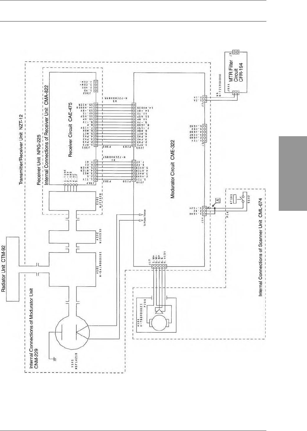
APPENDIX
APPENDIX-1
APPENDIX
INSTRUCTION MANUAL
APPENDIX
Fig. A1 NKE-2042 SCANNER INTERCONNECTION DIAGRAM
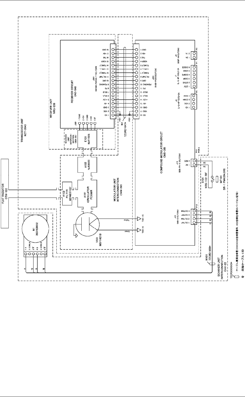
APPENDIX
APPENDIX-2
Fig. A2 NKE-2043 SCANNER INTERCONNECTION DIAGRAM
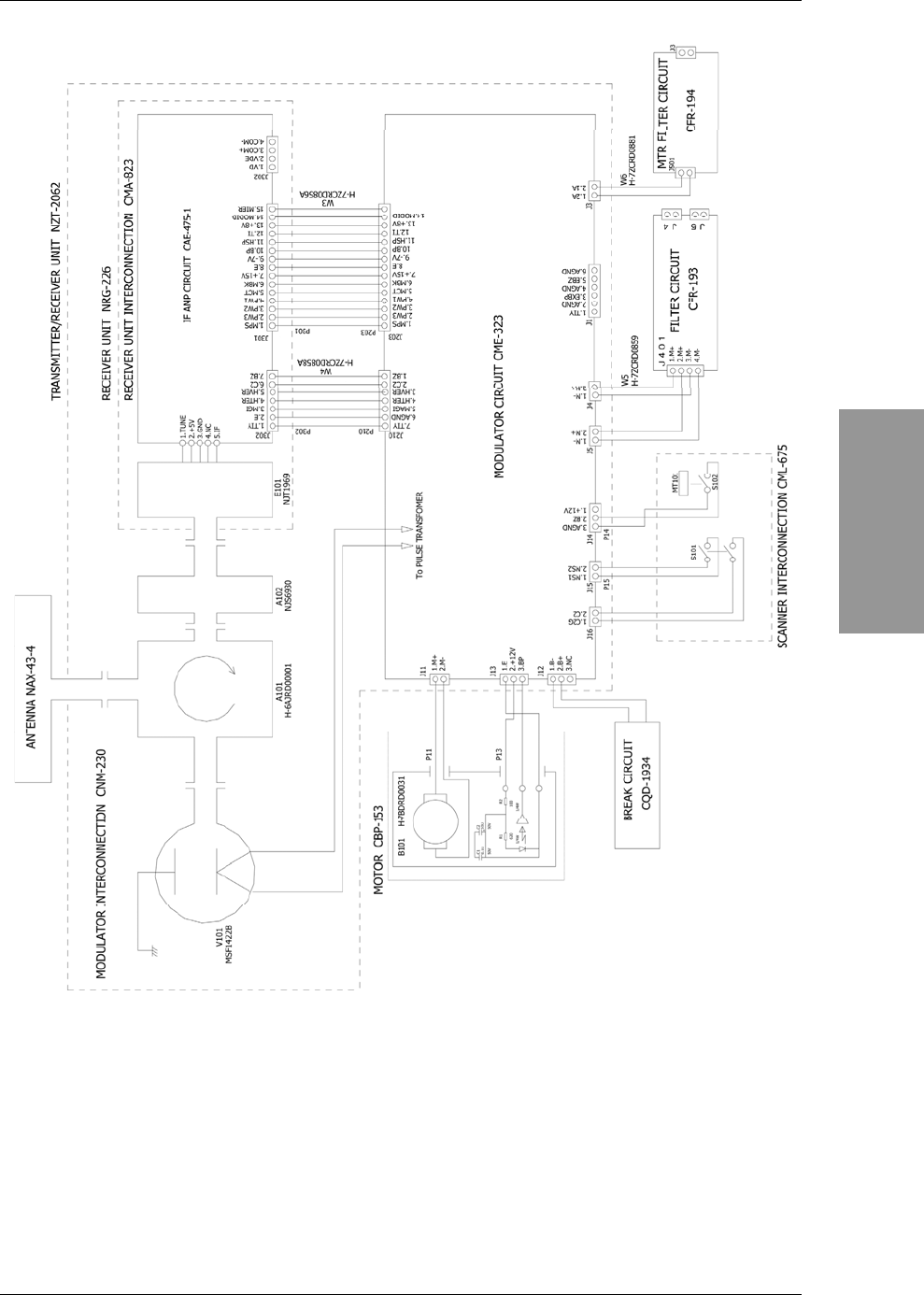
APPENDIX
APPENDIX-3
APPENDIX
INSTRUCTION MANUAL
Fig. A3 NKE-2062 SCANNER INTERCONNECTION DIAGRAM
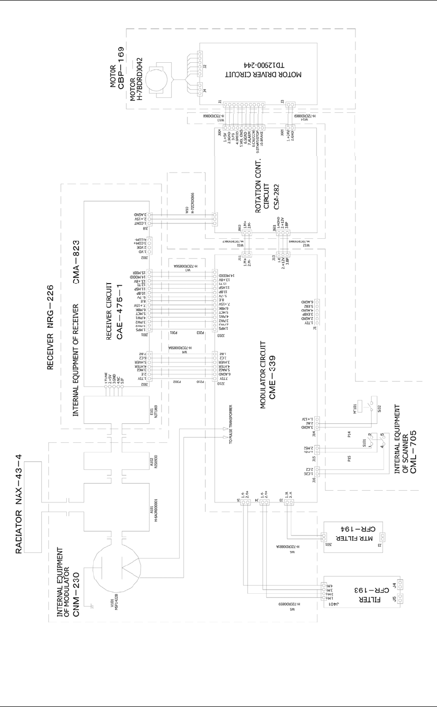
APPENDIX
APPENDIX-4
Fig. A4 NKE-2062HS SCANNER INTERCONNECTION DIAGRAM
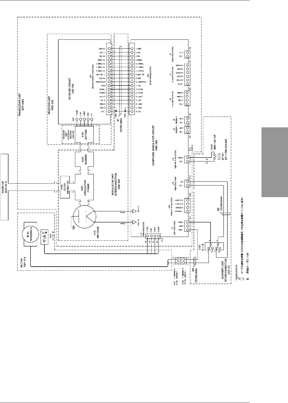
APPENDIX
APPENDIX-5
APPENDIX
INSTRUCTION MANUAL
Fig. A5 NKE-2063 SCANNER INTERCONNECTION DIAGRAM
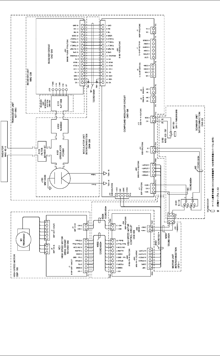
APPENDIX
APPENDIX-6
Fig. A6 NKE-2063HS SCANNER INTERCONNECTION DIAGRAM
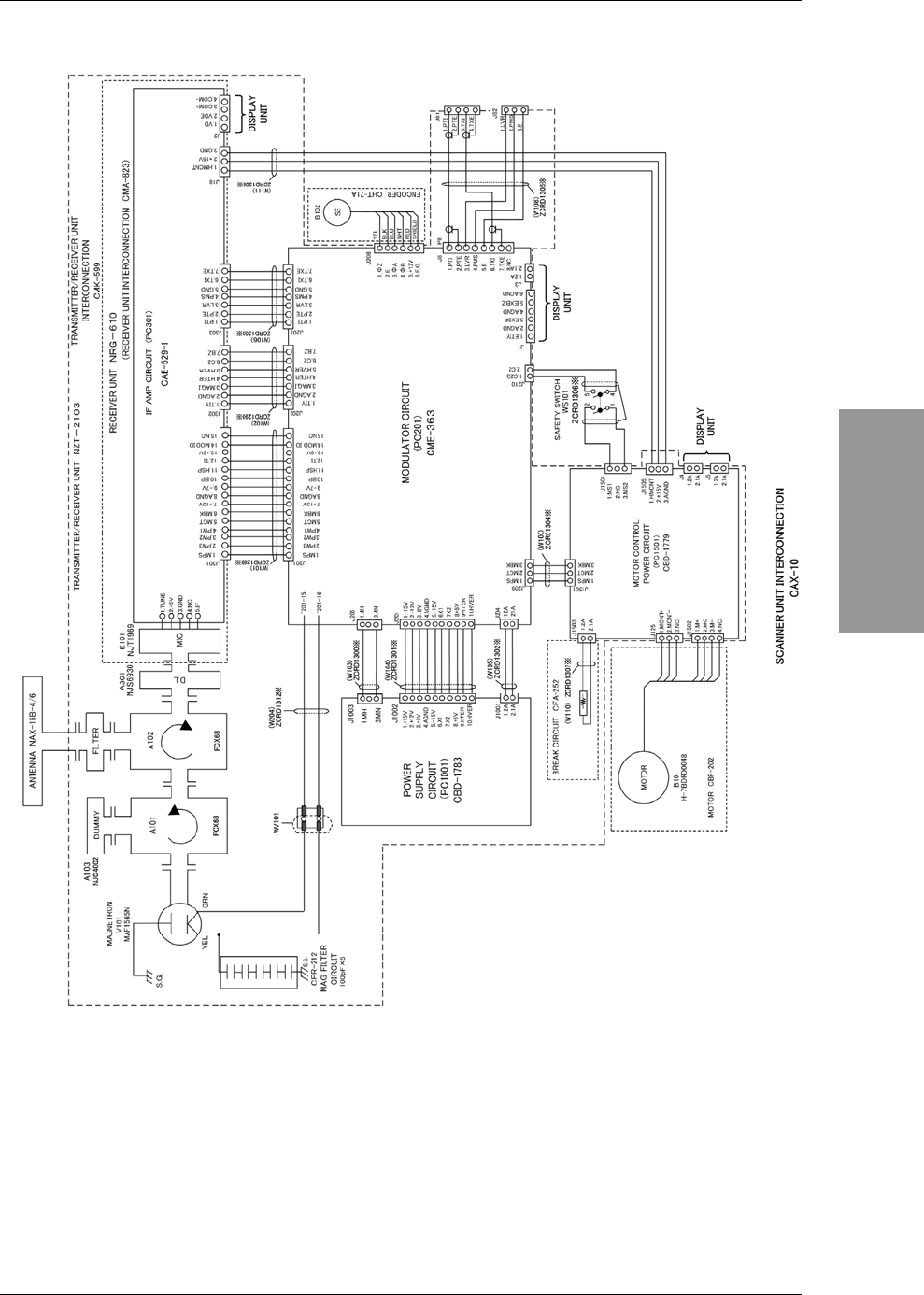
APPENDIX
APPENDIX-7
APPENDIX
INSTRUCTION MANUAL
Fig. A7 NKE-2103-4/4HS/6/6HS SCANNER INTERCONNECTION DIAGRAM
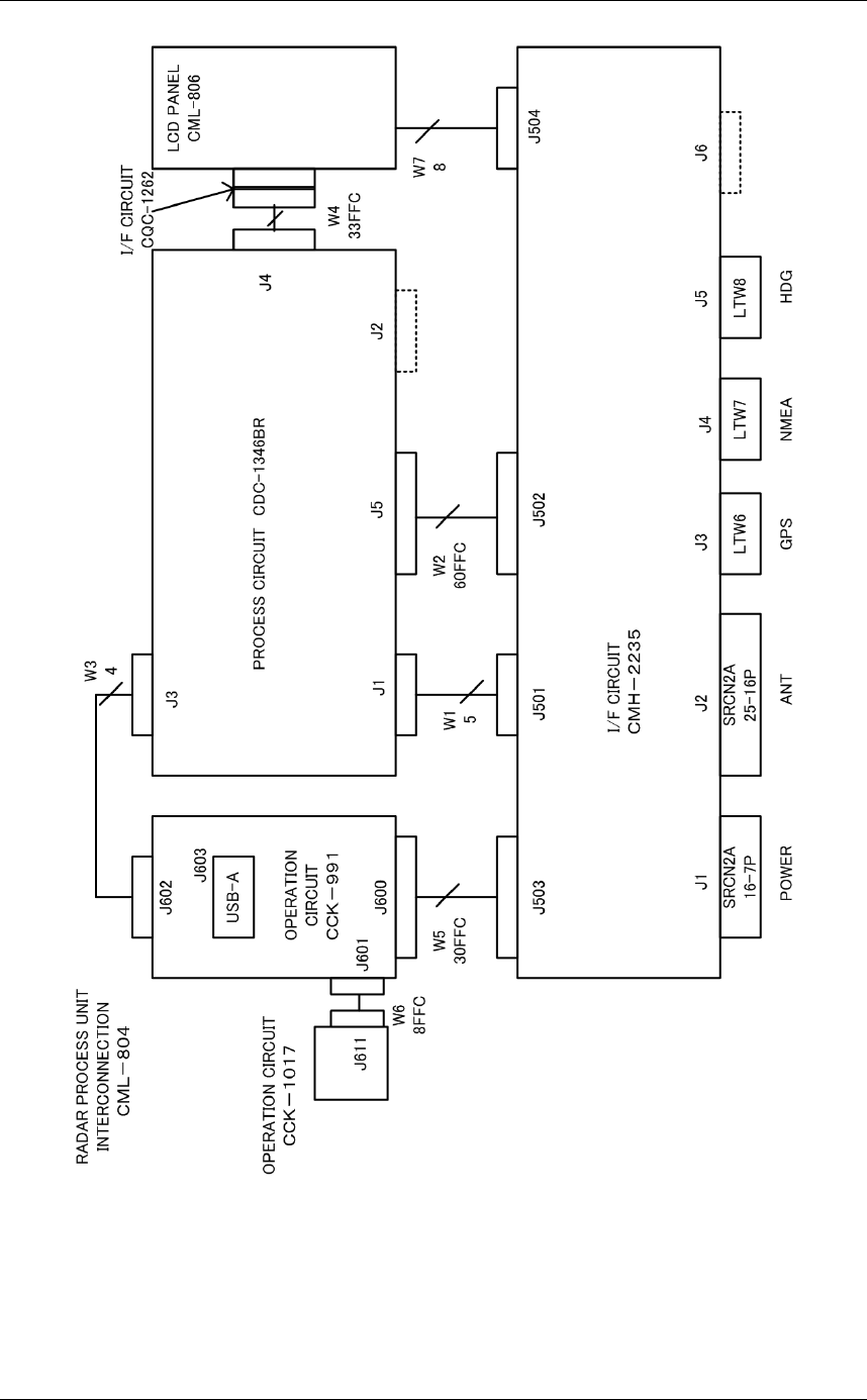
APPENDIX
APPENDIX-8
Fig. A8 NCD-2182 DISPLAY UNIT INTERCONNECTION DIAGRAM
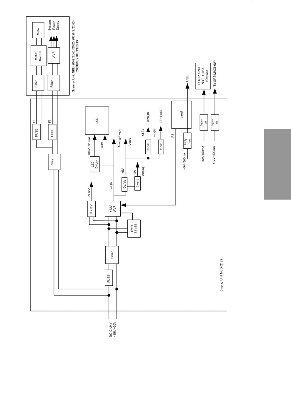
APPENDIX
APPENDIX-9
APPENDIX
INSTRUCTION MANUAL
Fig. A9 PRIMARY POWER SUPPLY DIAGRAM, TYPE JMA-3300
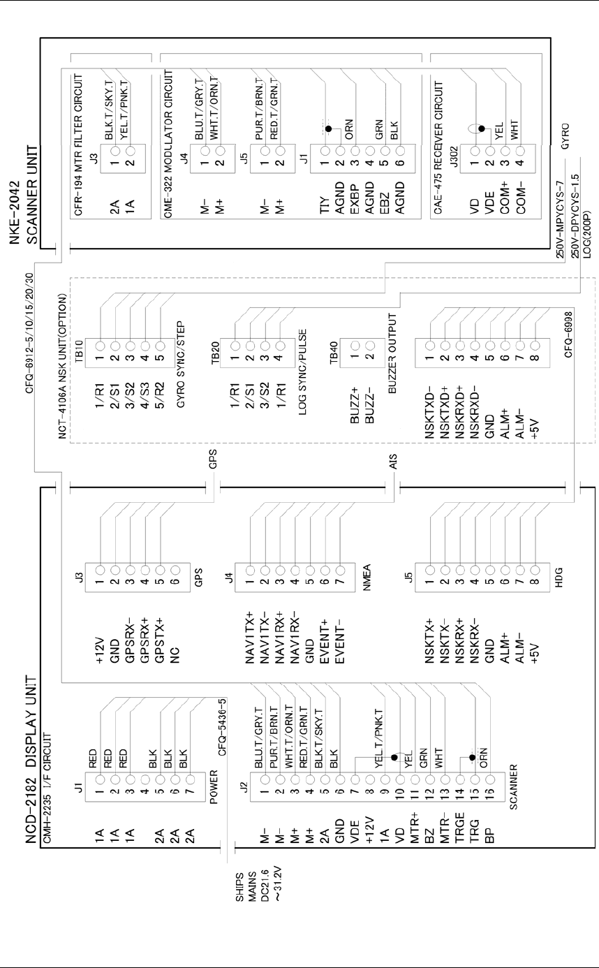
APPENDIX
APPENDIX-10
Fig. A10 JMA-3314 INTERCONNECTION DIAGRAM
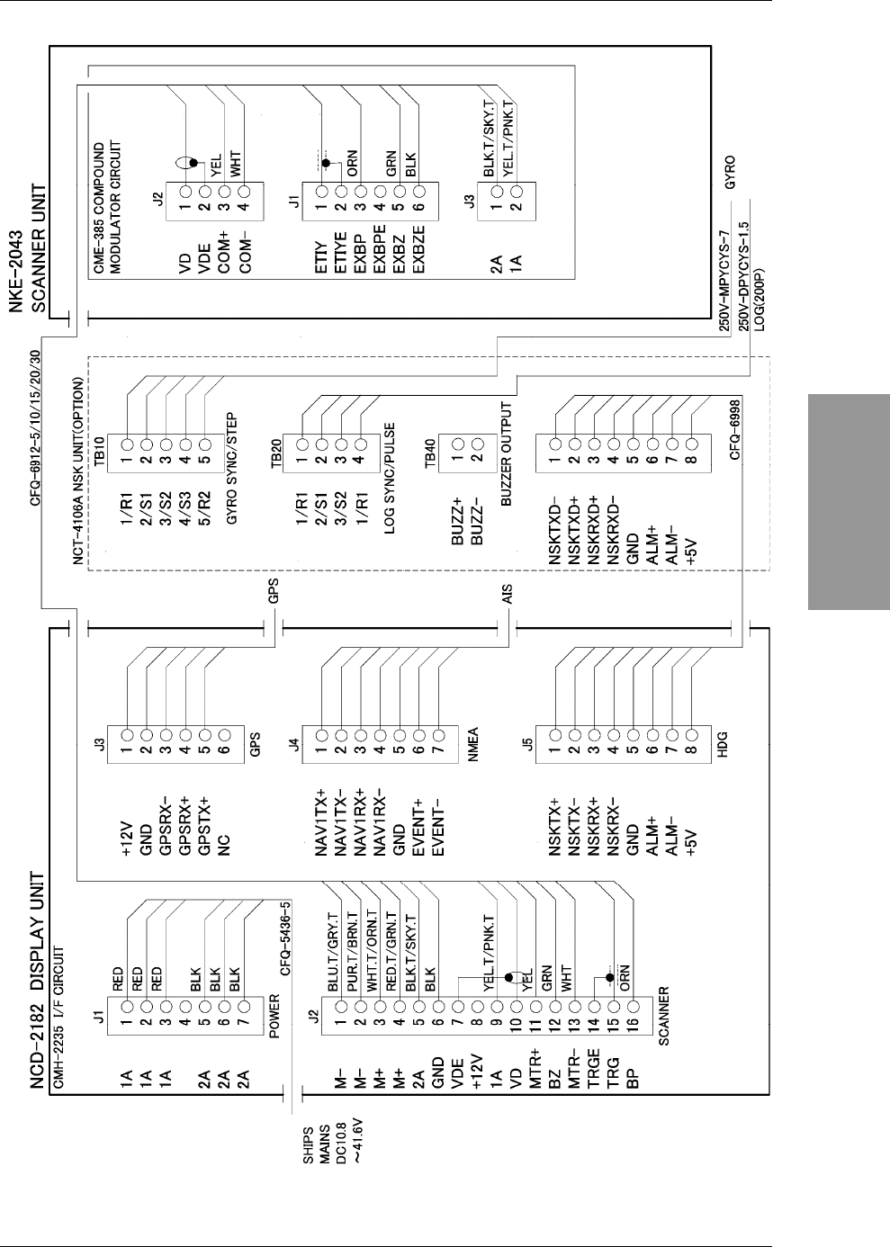
APPENDIX
APPENDIX-11
APPENDIX
INSTRUCTION MANUAL
Fig. A11 JMA-3334 INTERCONNECTION DIAGRAM
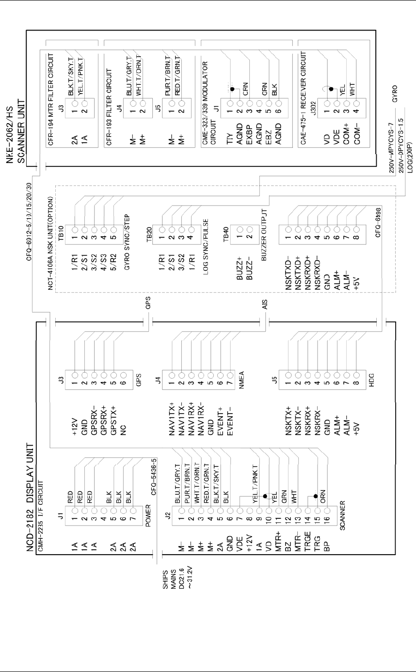
APPENDIX
APPENDIX-12
Fig. A12 JMA-3316/HS INTERCONNECTION DIAGRAM
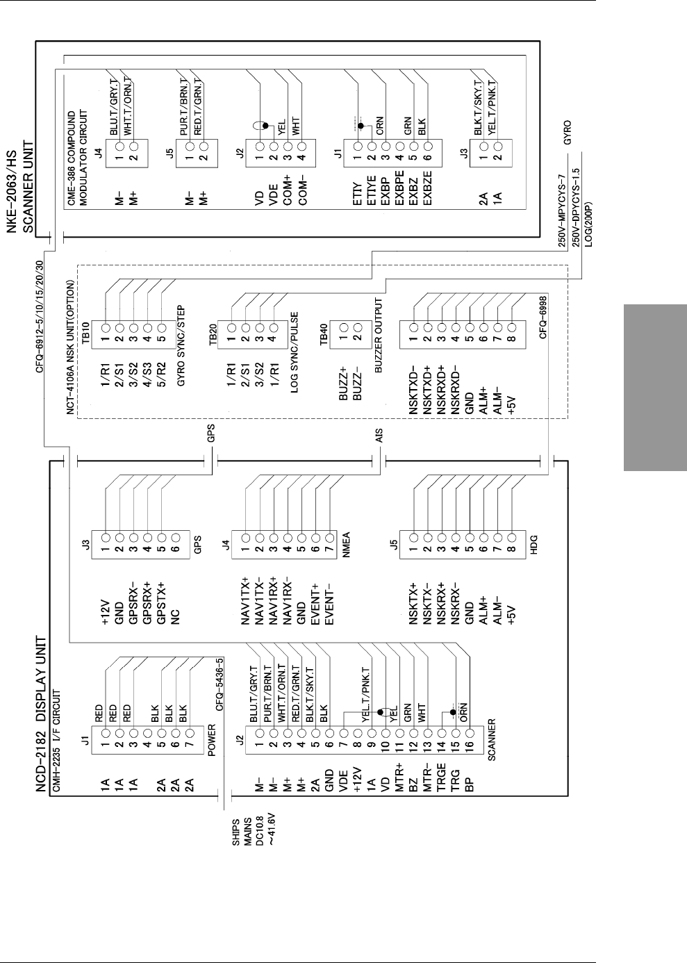
APPENDIX
APPENDIX-13
APPENDIX
INSTRUCTION MANUAL
Fig. A13 JMA-3336/HS INTERCONNECTION DIAGRAM
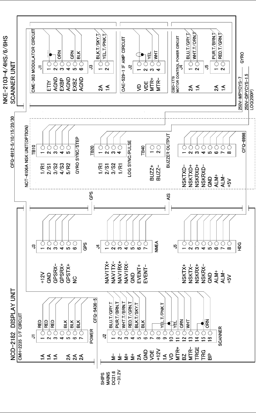
APPENDIX
APPENDIX-14
Fig. A14 JMA-3340-4/4HS/6/6HS INTERCONNECTION DIAGRAM

APPENDIX
APPENDIX-15
APPENDIX
INSTRUCTION MANUAL
Menu function list
0DLQ0HQX
㻴㼕㼟㼠㼛㼞㼥㻌 㻌
㻌㻌 㻌 㻌 㻌
㻌㻌
㻌㻌
㻌㻌 㻌
㻌㻌
㻌㻌
㻌㻌 㻌
㻌㻌
㻌㻌
㻌㻌 㻌
㻌㻌
㻌㻌
㻌㻌 㻌
㻌㻌
㻌㻌
㻌㻌 㻌
㻌㻌
㻌㻌
㻌㻌 㻌
㻌㻌
㻌㻌
㻌㻌 㻌
5$'$5(FKR
,5 2II/RZ0LGGOH+LJK
7DUJHW(QKDQFH 2II/HYHO/HYHO/HYHO
3URFHVV 2II6FDQ&25(/6FDQ&25(/6FDQ&25(/5HPDLQ3HDN+ROG
=RRP 2II2Q
9LGHR/DWLWXGH 1DUURZ1RUPDO:LGH:LGH
9LGHR1RLVH5HMHFWLRQ 2II/HYHO/HYHO/HYHO
㻌㻌 㻌 㻌㻌
7UDLOV
0$;,QWHUYDO 6KRUW0LGGOH/RQJ6XSHU/RQJ
0DUNHU
㻌㻌(%/6HWWLQJ 㻌)ORDWLQJ 2II6FUHHQ)L[//)L[
㻌㻌㻌 㻌%HDULQJ)L[ $QJOH)L[6FUHHQ)L[
㻌㻌(%/6HWWLQJ 㻌)ORDWLQJ 2II6FUHHQ)L[//)L[
㻌㻌㻌 㻌%HDULQJ)L[ $QJOH)L[6FUHHQ)L[
㻌㻌3DUDOOHO&XUVRU 㻌㻌 㻌
5DQJH6FDOH/LQN 2II2Q
㻌㻌㻌 㻌)ORDWLQJ 2II6FUHHQ)L[//)L[
㻌㻌%HDULQJ0RGH $QJOH)L[6FUHHQ)L[+HDGLQJ)L[
㻌㻌2QH%RWK6LGHV 2QH6LGH%RWK6LGHV
㻌㻌'LVSOD\)RU,QGLYLGXDO/LQH
㻌㻌 /LQH 2II2Q
㻌㻌 /LQH 2II2Q
㻌㻌 /LQH 2II2Q
㻌㻌 /LQH 2II2Q
㻌㻌 /LQH 2II2Q
㻌㻌 /LQH 2II2Q
㻌㻌 /LQH 2II2Q
&XUVRU
㻌 &XUVRU6L]H 6PDOO/DUJH
㻌
&XUVRU3DWWHUQ
'LVWDQFH8QLW 10NPVP
㻌㻌
㻌㻌 㻌5DQJH5LQJ 㻌㻌2II2Q
㻌㻌 㻌㻌㻌
'LVSOD\&RORU
'D\
6RIW.H\ 2II2Q
.H\ERDUG8QLW%ULOOLDQFH 2II/HYHO/HYHO/HYHO/HYHO
2XWHU33,
&RORU %ODFN%OXH:KLWH
,QQHU33,
&RORU %ODFN%OXH:KLWH
%ULOOLDQFH /HYHO/HYHO/HYHO/HYHO
&KDUDFWHU
&RORU :KLWH&\DQ*UHHQ%ODFN5HG
%ULOOLDQFH /HYHO/HYHO/HYHO/HYHO
5$'$5(FKR
&RORU <HOORZ*UHHQ%OXH:KLWH0DJHQWD&RORU&XVWRP
%ULOOLDQFH /HYHO/HYHO/HYHO/HYHO
5$'$57UDLOV7LPH
&RORU *UHHQ%OXH&\DQ
%ULOOLDQFH /HYHO/HYHO/HYHO/HYHO
5$'$57UDLOV$OO
&RORU *UHHQ%OXH&\DQ
%ULOOLDQFH /HYHO/HYHO/HYHO/HYHO
2ZQ6KLSV
&RORU &\DQ*UHHQ5HG:KLWH
%ULOOLDQFH /HYHO/HYHO/HYHO/HYHO
7DUJHW77$,6
&RORU &\DQ*UHHQ:KLWH
%ULOOLDQFH /HYHO/HYHO/HYHO/HYHO
(%/9503DUDOHOO
&RORU &\DQ%ODFN0DJHQWD:KLWH
%ULOOLDQFH /HYHO/HYHO/HYHO/HYHO
5DQJH5LQJ
&RORU &\DQ*UHHQ5HG:KLWH
%ULOOLDQFH /HYHO/HYHO/HYHO/HYHO
&XUVRU
&RORU :KLWH5HG0DJHQWD<HOORZ
%ULOOLDQFH /HYHO/HYHO/HYHO/HYHO

APPENDIX
APPENDIX-16
$=$ODUP=RQH
&RORU :KLWH*UHHQ2UDQJH%ODFN5HG
%ULOOLDQFH /HYHO/HYHO/HYHO/HYHO
'D\
'D\
'XVN
1LJKW
㻌&RQWURO 㻌㻌 㻌㻌 㻌
㻌㻌%HDULQJ7UXH5HODWLYH 㻌㻌 㻌7UXH5HODWLYH
㻌㻌㻌 㻌㻌 㻌
8VHU.H\
8VHU.H\ 2II9508QLW9508QLW$ODUP'LVSOD\
8VHU.H\ 2II9508QLW9508QLW$ODUP'LVSOD\
8VHU.H\ 2II9508QLW9508QLW$ODUP'LVSOD\
%X]]HU
.H\$&. 㹼
2SHUDWLRQ(UURU 㹼
&3$7&3$ 㹼
$=$ODUP=RQH 㹼
7DUJHW/RVW 㹼
6\VWHP$ODUP 㹼
2XWSXW%X]]HU
&3$7&3$ 2II2Q
$=$ODUP=RQH 2II2Q
7DUJHW/RVW 2II2Q
6\VWHP$ODUP 2II2Q
2XWRI5DQJH 2II2Q
)XQFWLRQ6HWWLQJ
)XQFWLRQ6HWWLQJ
)XQFWLRQ(QDEOH'LVDEOH 2II2Q
0RGH 6WDQGDUG&RDVW'HHSVHD)LVKQHW6WRUP&DOP5DLQ
%LUG/RQJ%XR\8VHU8VHU
,5 2II/RZ0LGGOH+LJK
3URFHVV 3URFHVV2II6FDQ&25(/6FDQ&25(/6FDQ&25(/
5HPDLQ3HDN+ROG
7DUJHW(QKDQFH 㻌2II/HYHO/HYHO/HYHO
㻌㻌 㻌㻌 㻌$87267&)7& 2II$87267&$872)7&
㻌㻌 㻌㻌 㻌3XOVH/HQJWK 105DQJH
10
10
10
10
10
10
1.(
10㸸6303
10㸸6303
10㸸6303
10㸸0303
10㸸03/3
10㸸/3
1.(
10㸸6303
10㸸6303
10㸸630303
10㸸630303
10㸸03/3/3
10㸸03/3/3
1.(
10㸸6303
10㸸6303
10㸸6303
10㸸0303
10㸸03/3
10㸸/3
1.(
10㸸6303
10㸸6303
10㸸630303
10㸸630303
10㸸03/3/3
10㸸03/3/3
1.(
10㸸6303
10㸸6303
10㸸630303
10㸸0303/3
10㸸03/3/3
10㸸03/3/3
APPENDIX
APPENDIX-17
APPENDIX
INSTRUCTION MANUAL
VP5DQJH
VP
VP
VP
VP
VP
VP
1.(
VP㸸6303
VP㸸6303
VP㸸6303
VP㸸0303
VP㸸03/3
VP㸸/3
1.(
VP㸸6303
VP㸸6303
VP㸸630303
VP㸸630303
VP㸸03/3/3
VP㸸03/3/3
1.(
VP㸸6303
VP㸸6303
VP㸸6303
VP㸸0303
VP㸸03/3
VP㸸/3
1.(
VP㸸6303
VP㸸6303
VP㸸630303
VP㸸630303
VP㸸03/3/3
VP㸸03/3/3
1.(
VP㸸6303
VP㸸6303
VP㸸630303
VP㸸0303/3
VP㸸03/3/3
VP㸸03/3/3
NP5DQJH
NP
NP
NP
NP
NP
1.(
NP㸸6303
NP㸸6303
NP㸸0303
NP㸸03/3
NP㸸/3
1.(
NP㸸6303
NP㸸630303
NP㸸630303
NP㸸03/3/3
NP㸸03/3/3
1.(
NP㸸6303
NP㸸6303
NP㸸0303
NP㸸03/3
NP㸸/3
1.(
NP㸸6303
NP㸸630303
NP㸸630303
NP㸸03/3/3
NP㸸03/3/3
1.(
NP㸸6303
NP㸸630303
NP㸸0303/3
NP㸸03/3/3
NP㸸03/3/3
㻌㻌㻌9LGHR/DWLWXGH 1DUURZ1RUPDO:LGH:LGH
9LGHR1RLVH5HMHFWLRQ 2II/HYHO/HYHO/HYHO
7UDLOV,QWHUYDO 㻿㼔㼛㼞㼠㻦㻌 㻌
2IIVHFVHFPLQPLQPLQPLQPLQ
PLQPLQPLQ&217
㻹㼕㼐㼐㼘㼑㻦㻌 㻌
㻻㼒㼒㻌㻛㻌㻟㻜㼟㼑㼏㻌㻛㻌㻝㼙㼕㼚㻌㻛㻌㻞㼙㼕㼚㻌㻛㻌㻟㼙㼕㼚㻌㻛㻌㻠㼙㼕㼚㻌㻛㻌㻡㼙㼕㼚㻌㻛㻌㻢㼙㼕㼚㻌㻛㻌㻝㻜㼙㼕㼚㻌㻛㻌 㻌
㻝㻡㼙㼕㼚㻌㻛㻌㻟㻜㼙㼕㼚㻌㻛㻌㻯㻻㻺㼀㻌
㻸㼛㼚㼓㻦㻌 㻌
㻻㼒㼒㻌㻛㻌㻝㼙㼕㼚㻌㻛㻌㻞㼙㼕㼚㻌㻛㻌㻟㼙㼕㼚㻌㻛㻌㻠㼙㼕㼚㻌㻛㻌㻡㼙㼕㼚㻌㻛㻌㻢㼙㼕㼚㻌㻛㻌㻝㻜㼙㼕㼚㻌㻛㻌㻝㻡㼙㼕㼚㻌㻛㻌 㻌
㻟㻜㼙㼕㼚㻌㻛㻌㻝㼔㼞㻌㻛㻌㻯㻻㻺㼀㻌
㻿㼡㼜㼑㼞㻌㻸㼛㼚㼓㻦㻌 㻌
㻻㼒㼒㻌㻛㻌㻟㻜㼙㼕㼚㻌㻛㻌㻝㼔㼞㻌㻛㻌㻞㼔㼞㻌㻛㻌㻟㼔㼞㻌㻛㻌㻠㼔㼞㻌㻛㻌㻡㼔㼞㻌㻛㻌㻢㼔㼞㻌㻛㻌㻝㻜㼔㼞㻌㻛㻌㻝㻞㼔㼞㻌㻛㻌㻯㻻㻺㼀㻌
㻌㻌 㻌㻌 㻌7UDLOV0RGH 7UXH5HODWLYH
7UDLOV5()/HYHO /HYHO/HYHO/HYHO/HYHO
7LPH$OO&RPELQH 2II2Q
0$;,QWHUYDO 㻌6KRUW0LGGOH/RQJ6XSHU/RQJ
㻌 35) 1RUPDO(FRQRP\+LJK3RZHU
$QWHQQD+HLJKW 'HIDXOW㹼P㹼P㹼PP㹼
6HDZHHG6KLS720$.20$,865LYHU(85LYHU
6DYH3UHVHQW6DWWH
6HW0RGH'HIDXOW
,QLWLDOL]H
)XQFWLRQ6HWWLQJ
)XQFWLRQ6HWWLQJ
)XQFWLRQ6HWWLQJ
7DUJHW
)XQFWLRQ2Q2II
77 2II2Q

APPENDIX
APPENDIX-18
$,6 2II2Q
&3$/LPLW 㹼QP
7&3$/LPLW 㹼PLQ
&3$5LQJ 2II2Q
7DUJHW1XPEHU'LVSOD\
77 2II2Q
$,6 2II2Q
7DUJHW1XPEHU$OORFDWLRQ
77 㹼
$,6 㹼
2ZQ6KLSV 㹼
&XUVRU 㹼
$/5$ODUP)URP$,6 2II2Q
$,6'LVSOD\7DUJHW
$,6'HVWLQDWLRQ6KLS 㹼
$,65HWULHYHG9HVVHO
006,1XPEHU6HWWLQJ
5HWULHYHG9HVVHOLQIR 㹼
5HWULHYHG9HVVHOLQIR 㹼
5HWULHYHG9HVVHOLQIR 㹼
5HWULHYHG9HVVHOLQIR 㹼
5HWULHYHG9HVVHOLQIR 㹼
5HWULHYHG9HVVHOLQIR 㹼
5HWULHYHG9HVVHOLQIR 㹼
5HWULHYHG9HVVHOLQIR 㹼
5HWULHYHG9HVVHOLQIR 㹼
5HWULHYHG9HVVHOLQIR 㹼
$,6)LOWHU 㹼10
)LOH2SHUDWLRQ
㻿㼍㼢㼑㻌
$,65HWULHYHG9HVVHO
㻸㼛㼍㼐㻌
$,65HWULHYHG9HVVHO
㻱㼞㼍㼟㼑㻌
$,65HWULHYHG9HVVHO
5$'$5$ODUP
5$'$5$ODUP/HYHO /HYHO/HYHO/HYHO/HYHO
5$'$5$ODUP/HYHO /HYHO/HYHO/HYHO/HYHO
3ORW
:D\SRLQW'LVSOD\ 2II2Q
0DUN
㻌㻌㻌 㻌0DUN6L]H 6PDOO/DUJH
'LVSOD\0DUN&RORU
$OO $OO,QGLYLGXDO
:KLWH 2II2Q
&\DQ 2II2Q
%OXH 2II2Q
*UHHQ 2II2Q
<HOORZ 2II2Q
0DJHQWD 2II2Q
5HG 2II2Q
'LVSOD\0DUN7\SH
$OO $OO,QGLYLGXDO
㹖 2II2Q
㸩 2II2Q
㹗 2II2Q
2II2Q
0DUN/LVW
/LQH
'LVSOD\/LQH&RORU
$OO $OO,QGLYLGXDO
:KLWH 2II2Q
&\DQ 2II2Q
%OXH 2II2Q
*UHHQ 2II2Q
<HOORZ 2II2Q
0DJHQWD 2II2Q
5HG 2II2Q
'LVSOD\/LQH7\SH
㻌㻌 $OO $OO,QGLYLGXDO
㻌㻌 ̿̿ 2II2Q
㻌㻌 2II2Q
㻌㻌 㸫㸫㸫㸫 2II2Q
/LQH/LVW
2ZQ7UDFN 㻌㻌
'LVSOD\2ZQ7UDFN&RORU
$OO $OO,QGLYLGXDO
:KLWH 2II2Q
&\DQ 2II2Q
%OXH 2II2Q
*UHHQ 2II2Q
<HOORZ 2II2Q
0DJHQWD 2II2Q
5HG 2II2Q
'LVSOD\2ZQ7UDFN7\SH
㻌㻌 $OO $OO,QGLYLGXDO

APPENDIX
APPENDIX-19
APPENDIX
INSTRUCTION MANUAL
㻌㻌 ̿̿ 2II2Q
㻌㻌 2II2Q
㻌㻌 㸫㸫㸫㸫 2II2Q
㻌㻌&OHDU2ZQ7UDFN&RORU7\SH
㻌㻌 &OHDU2ZQ7UDFN&RORU $OO:KLWH&\DQ%OXH*UHHQ<HOORZ0DJHQWD5HG
㻌㻌 &OHDU2ZQ7UDFN7\SH $OO̿̿㸫㸫㸫㸫
㻌㻌㻌 &OHDU2ZQ7UDFN
)LOH2SHUDWLRQ 㻌㻌
㻌㻌 㻌㻌 㻿㼍㼢㼑㻌
㻌㻌 㻌㻌㻌 0DUN/LQH
㻌㻌 㻌㻌㻌 2ZQ7UDFN
㻌
㻌㻌㻌 㻸㼛㼍㼐㻌
㻌㻌 㻌㻌㻌 0DUN/LQH
㻌㻌 㻌㻌㻌 2ZQ7UDFN
㻌㻌 㻌㻌㻱㼞㼍㼟㼑㻌
㻌㻌 㻌㻌㻌 0DUN/LQH
㻌㻌 㻌㻌㻌 2ZQ7UDFN
㻌㻌 㻌㻌㻌
㻌 㼀㼕㼙㼑㼐㻌㼀㼄㻌 㻌 㻌 㻌 㻌
㻌 㻌 㻌 㼀㼕㼙㼑㼐㻌㼀㼄㻌 㻌 㻌 2II2Q
㻌 㻌 㻌 㼀㼄㻌㼀㼕㼙㼑㻌 㻌 㻌 㹼㻿㼏㼍㼚
㻌 㻌 㻌 㻿㼠㼍㼚㼐㼎㼥㻌㼀㼕㼙㼑㻌 㻌 㻌 㹼㼙㼕㼚
㻌㻌 㻌㻌 㻌㻌
7HVW
6\VWHP,QIRUPDWLRQ
㻌
6\VWHP7LPH
㻌
6FDQQHU,QIRUPDWLRQ
㻌
+DUGZDUH,QIRUPDWLRQ
(UURU/RJ
㻰㼕㼟㼜㼘㼍㼥㻌
(UDVH
/LQH0RQLWRU
6HOI7HVW
.H\7HVW
%X]]HU7HVW
.H\/LJKW7HVW
0RQLWRU'LVSOD\7HVW
3DWWHUQ
3DWWHUQ
3DWWHUQ
3DWWHUQ
3DWWHUQ
3DWWHUQ
3DWWHUQ
3DWWHUQ
5HG 㹼
*UHHQ 㹼
%OXH 㹼
'LVSOD\
0HPRU\7HVW
/LQH7HVW
6HQVRU7HVW
$GMXVW0HQX
%DVLF$GMXVWPHQW
%HDULQJ$GMXVWPHQW 㹼r
5DQJH$GM\XVWPHQW 㹼
7XQH$GMXVWPHQW 㹼
$QWHQQD+HLJKW 㹼P㹼P㹼PP㹼
/DQJXDJH (QJOLVK-DSDQHVH)UHQFK*HUPDQ6SDQLVK,WDOLDQ
3RUWXJXHVH1RUZHJLDQ&XVWRP
5$'$5(FKR
1RLVH/HYHO 㹼
0DLQ%DQJ6XSSUHVVLRQ
0DLQ%DQJ6XSSUHVVLRQ/HYHO 㹼
0DLQ%DQJ6XSSUHVVLRQ$UHD 㹼
7DUJHW(QKDQFH/HYHO /HYHO/HYHO/HYHO/HYHO
*DLQ
3UHVHW 㹼
6HD
67&&XUYH6HOHFW 6HD5LYHU
67&6ORSH&RUUHFWLRQ 㹼
67&2IIVHW 㹼))
5DLQ
)7&&XUYH6HOHFW 6HD5LYHU
)7&6ORSH&RUUHFWLRQ 㹼
)7&2IIVHW 㹼))
7UDLOV
7UDLOV6XSSUHVVLRQ'LVWDQFH 㹼P
77
9HFWRU&RQVWDQW 㹼
*DWH'LVSOD\ 2II2Q
*DWH6L]H 㹼

APPENDIX
APPENDIX-20
6FDQQHU
6ORSH&RUUHFWLRQ 㹼
35))LQH7XQLQJ 㹼
6WDJJHU7ULJJHU 2II2Q
6FDQQHU5RWDWLRQ6SHHG
7KHRSWLRQVYDU\GHSHQGLQJ
RQWKHVFDQQHU
63 㹼
03 㹼
03 㹼
/3 㹼
/3 㹼
/3 㹼
35) 1RUPDO(FRQRP\+LJK3RZHU
6DIW\6ZLWFK 7;2II6WDQGE\7;2Q,JQRUH(UURU
7XQH3HDN$GMXVWPHQW 㹼
7XQH,QGLFDWRU 㹼
,)'HYLFH
6HW*<52 㹼r
+HDGLQJ(TXLSPHQW $872*<52&RPSDVV*360DQXDO
0DQXDO+HDGLQJ 㹼r
6SHHG(TXLSPHQW *36/RJ/RJ0DQXDO
0DQXDO6SHHG 㹼NQ
0$*&RPSDVV6HWWLQJ
+HDGLQJ&RUUHFWLRQ 2II2Q
&RUUHFW9DOXH :㹼(r
&203RUW6HWWLQJ
%DXG5DWH
㻌㻌㻌*<52&RPSDVV 㻌$㼁㼀㻻ESVESV
㻌㻌㻌*36 㻌$㼁㼀㻻ESVESV
㻌㻌㻌10($ 㻌$㼁㼀㻻ESVESV
㻌㻌㻌10($ 㻌$㼁㼀㻻ESVESV
5;6HQWHQFH
*36//
**$ 2II2Q
50& 2II2Q
50$ 2II2Q
*16 2II2Q
*// 2II2Q
*36&2*62*
50& 2II2Q
50$ 2II2Q
97* 2II2Q
+HDGLQJ
7+6 2II2Q
+'7 2II2Q
+'* 2II2Q
+'0 2II2Q
9+: 2II2Q
'HSWK
'37 2II2Q
'%6 2II2Q
'%7 2II2Q
'%. 2II2Q
:LQG
0:9 2II2Q
9:7 2II2Q
9:5 2II2Q
:37
50% 2II2Q
%:& 2II2Q
%:5 2II2Q
5;3RUW
*36 $872*<52&RPSDVV*3610($10($
/RJ $872*<52&RPSDVV*3610($10($
/RJ $872*<52&RPSDVV*3610($10($
'HSWK $872*<52&RPSDVV*3610($10($
7HPSHUDWXUH $872*<52&RPSDVV*3610($10($
:LQG $872*<52&RPSDVV*3610($10($
:37 $872*<52&RPSDVV*3610($10($
5DWHRI7XUQ $872*<52&RPSDVV*3610($10($
5XGGHU $872*<52&RPSDVV*3610($10($
7;3RUW
770 2II*<52&RPSDVV*3610($10($
7// 2II*<52&RPSDVV*3610($10($
77' 2II*<52&RPSDVV*3610($10($
7/% 2II*<52&RPSDVV*3610($10($
**$ 2II*<52&RPSDVV*3610($10($
*// 2II*<52&RPSDVV*3610($10($
50& 2II*<52&RPSDVV*3610($10($
*16 2II*<52&RPSDVV*3610($10($
97* 2II*<52&RPSDVV*3610($10($
26' 2II*<52&RPSDVV*3610($10($
56' 2II*<52&RPSDVV*3610($10($
7+6 2II*<52&RPSDVV*3610($10($

APPENDIX
APPENDIX-21
APPENDIX
INSTRUCTION MANUAL
+'7 2II*<52&RPSDVV*3610($10($
7;'DWD)RUPDW
7;,QWHUYDO 㹼㼟㼑㼏
10($9HUVLRQ 999
10($7DONHU 1RUPDO*3
7DUJHW,QIRUPDWLRQ7;
7;7DUJHW 77$,677࣭$,6
㻌
㻌㻌㻌 㻌770'LVWDQFH$FFXUDF\
77$YHUDJH0RGH 2II2Q
77$YHUDJH6FDQ 㹼
*36
*366HWWLQJ
㻌 10($9HUVLRQ $㼁㼀㻻9㼂㻞㻚㻝9
㻌
㻌㻌㻌&RUUHFWLRQ0HWKRG 㻌*366LQJOH6%$6%HDFRQ$872
㻌㻌 㻌㻌)L[0RGH ''$872
㻌㻌 㻌㻌(OHYDWH0DVN 㹼r
+'23
/DWLWXGHDQG/RQJLWXGH 㹼VHF5㹼
62* 㹼VHF5㹼
&2* 㹼VHF5㹼
㻌㻌 㻌㻌 㻌6PRRWKLQJ 㹼VHF5㹼5
㹼VHF5㹼5
6PRRWKLQJ VHFVHFVHF
5$,0$FFXUDF\/HYHO 2IIPPPP
㻌㻌 㻌㻌 㻌([FOXVLRQ6DWHOOLWH
㻌㻌 㻌㻌 㻌 ([FOXVLRQ6DWHOOLWH 㹼
㻌㻌 㻌㻌 㻌 ([FOXVLRQ6DWHOOLWH 㹼
㻌㻌 㻌㻌 㻌 ([FOXVLRQ6DWHOOLWH 㹼
㻌㻌 㻌㻌 㻌 ([FOXVLRQ6DWHOOLWH 㹼
㻌㻌 㻌㻌 㻌 ([FOXVLRQ6DWHOOLWH 㹼
㻌㻌 㻌㻌 㻌 ([FOXVLRQ6DWHOOLWH 㹼
6HQG'DWD
*36$GMXVW
3RVLWLRQ
$QWHQQD+HLJKW 㹼P
7LPH 㹼
'DWH 㹼
0DVWHU5HVHW
6HQG'DWD

APPENDIX
APPENDIX-22
%HDFRQ6HWWLQJ
㻌
6HOHFW $8720DQXDO
)UHTXHQF\ N+]
%DXG/DWH ESV
6HQG'DWD
6%$66HWWLQJ
㻌
㻌㻌㻌 㻌6DWHOOLWH6HDUFK $8720DQXDO
5DQJLQJ 2II2Q
㻌㻌 㻌㻌 㻌6%$66DWHOOLWH1XPEHU 㹼
6HQG'DWD
㻌㻌 㻌'LVSOD\*365HFHLYH6WDWXV㻌
㻌㻌 㻌/25$16HWWLQJ 㻌
㻌㻌 㻌㻌 㻌'LVSOD\7LPH=RQH 2II/25$1$/25$1&
㻌㻌 㻌㻌 㻌/25$1$
㻌㻌 㻌㻌 㻌㻌 6HOHFW 6㹼+
<RXFDQVHWWKHIROORZLQJYDOXHVRQO\
66666////
66666666+++
㻌㻌 㻌㻌 㻌㻌 6HOHFW 6DPHDV6HOHFW
㻌㻌 㻌㻌 㻌㻌 7'&RUUHFWLRQ 㹼PVHF
㻌㻌 㻌㻌 㻌㻌 7'&RUUHFWLRQ 㹼PVHF
㻌㻌㻌 㻌/25$1&
㻌㻌㻌 㻌㻌 &KDLQ 㹼
<RXFDQVHWWKHIROORZLQJYDOXHVRQO\
㻌㻌㻌 㻌㻌 7' 㹼
㻌㻌㻌 㻌㻌 7' 㹼
㻌㻌㻌 㻌㻌 7'&RUUHFWLRQ 㹼PVHF
㻌㻌㻌 㻌㻌 7'&RUUHFWLRQ 㹼PVHF
&RQWURO
㻌㻌6RIW.H\0HQX6HWWLQJ 㻌
(%/ 2II2Q
(%/ 2II2Q
950 2II2Q
950 2II2Q
3DUDOOHO&XUVRU 2II2Q
9HFWRU/HQJWK 2II2Q
7UDLOV 2II2Q
$,6 2II2Q
77 2II2Q
$ODUP 2II2Q
$ODUP 2II2Q
'LVSOD\6FUHHQ 2II2Q
7050 2II2Q
%HDULQJ0RGH 2II2Q
3XOVH/HQJWK 2II2Q
2II&HQWHU 2II2Q
6\PERO'LVSOD\ 2II2Q
02% 2II2Q
0DUN 2II2Q
/LQH 2II2Q
2ZQ7UDFN 2II2Q
(YHQW0DUN 2II2Q
$,6)LOWHU 2II2Q
7//7; 2II2Q
6RIW.H\7LPH2XW 㹼VHF
&URVV.H\*DLQ 㹼
0XOWL&RQWURO
(%/ 㹼
950 㹼
㻌㻌&RPPRQ 㻌㹼
*DLQ&RQWURO
5HVSRQVH/HYHO 㹼
*DLQ0,13UHVHW 㹼
*DLQ0$;3UHVHW 㹼
6HD&RQWURO
5HVSRQVH/HYHO 㹼
6HD0,13UHVHW 㹼
6HD0$;3UHVHW 㹼
5DLQ&RQWURO
5HVSRQVH/HYHO 㹼
5DLQ0,13UHVHW 㹼
5DLQ0$;3UHVHW 㹼
0DLQWHQDQFH
3DUWLDO5HVHW
5$'$5(FKR
㻌㻌㻌 㻌)XQFWLRQ6HWWLQJ
%DVLF$GMXVWPHQW
0DLQ0HQX
$GMXVW0HQX
6\VWHP,QIRUPDWLRQ
6\VWHP,QIRUPDWLRQ
$OO0HQX
㻌
$OO5HVHW

APPENDIX
APPENDIX-23
APPENDIX
INSTRUCTION MANUAL
6\VWHP7LPH&OHDU
6FDQQHU7LPH&OHDU
7;7LPH&OHDU
0RWRU7LPH&OHDU
6FDQQHUWR'LVSOD\8QLW
'LVSOD\8QLWWR6FDQQHU
7DEOH8SGDWH
67&&XUYH
&RORU
㻌㻌 㻌㻌 㻌,QLWLDO9DOXH
5$'$5(FKR
㻌㻌 㻌㻌 㻌 )XQFWLRQ6HWWLQJ
%DVLF$GMXVWPHQW
㻌㻌 㻌㻌 㻌㻌 0DLQ0HQX
㻌㻌 㻌㻌 㻌㻌 $GMXVW0HQX
㻌㻌 㻌㻌 㻌㻌 6\VWHP,QIRUPDWLRQ
㻌㻌 㻌㻌 㻌㻌 6\VWHP,QIRUPDWLRQ
$OO0HQX
,QVHUW/DQJXDJH
(FKR6LPXODWLRQ
,QWHUQDO6HWWLQJ
,QWHUQDO0HPRU\WR86%
5$'$5(FKR
㻌㻌 㻌㻌 㻌 )XQFWLRQ6HWWLQJ
%DVLF$GMXVWPHQW
0DLQ0HQX
$GMXVW0HQX
6\VWHP,QIRUPDWLRQ
6\VWHP,QIRUPDWLRQ
$OO0HQX
86%WR,QWHUQDO0HPRU\
5$'$5(FKR
㻌㻌 㻌㻌 㻌 )XQFWLRQ6HWWLQJ
%DVLF$GMXVWPHQW
0DLQ0HQX
$GMXVW0HQX
6\VWHP,QIRUPDWLRQ
6\VWHP,QIRUPDWLRQ
$OO0HQX
86%)RUPDW
6\VWHP6HWWLQJ
㻌
0DVWHU6ODYH'(02 0DVWHU6ODYH'HPR
8QLW
5DQJH 10NPVP
'LVWDQFH 10NPVP
6SHHG NQNPKPSK
'HSWK IWIPPXVHU
8VHU'HSWK 㹼P
7HPSHUDWXUH Υ㺽 )
:LQG PVNPKNQ
㻌㻌6L]H/RFDWLRQ6HWWLQJ PIW
0RYH2ZQ6KLS
6KLSV0RYH //&2*62*
5DQJH
10
10 2II2Q
10 2II2Q
10 2II2Q
10 2II2Q
10 2II2Q
10 2II2Q
10 2II2Q
10 2II2Q
10 2II2Q
10 2II2Q
10 2II2Q
10 2II2Q
10 2II2Q
NP
NP 2II2Q
NP 2II2Q
NP 2II2Q
NP 2II2Q
NP 2II2Q
NP 2II2Q
VP
VP 2II2Q
VP 2II2Q
VP 2II2Q
VP 2II2Q
VP 2II2Q
VP 2II2Q
VP 2II2Q
VP 2II2Q

APPENDIX
APPENDIX-24
㻌㻌 㻌㻌 㻌 VP 2II2Q
㻌㻌 㻌㻌 㻌 VP 2II2Q
㻌㻌 㻌㻌 㻌 VP 2II2Q
㻌㻌 㻌㻌 㻌 VP 2II2Q
㻌
VP 2II2Q
'LVSOD\6FUHHQ
2ZQ9HFWRU/LQH:LGWK 㹼
2ZQ2XWOLQH
2Q2II 2II2Q
,QSXW2XWOLQH6L]H
㻌
$OO/HQJWK 㹼P
$OO:LGWK 㹼P
*36$QWHQQD/HQJWK 㹼P
*36$QWHQQD6LGH 㹼P
6FDQQHU/HQJWK 㹼P
6FDQQHU6LGH 㹼P
%DUJH2XWOLQH
2Q2II 2II2Q
,QSXW2XWOLQH6L]H
㻌
$OO/HQJWK 㹼P
$OO:LGWK 㹼P
%DUJH3RVLWLRQ/HQJWK 㹼P
%DUJH3RVLWLRQ6LGH 㹼P
%HDULQJ0DUNHU
%HDULQJ 2II2Q
%HDULQJ6WHS 㹼r
6WDQGE\1XPHULF'LVSOD\ 2II2Q
2SHUDWLRQ1XPHULF'LVSOD\ 2II2Q
/RFDWLRQ&KDQJH
㻿㼏㼞㼑㼑㼚㻌㻝㻌
1XPHULF,QIRUPDWLRQ
/DUJH
㻌2II$;*&RXUVH6SHHG/DWLWXGH/RQJLWXGH
1XPHULF'LVSOD\ 㻌2II
2ZQ+HDGLQJ6SHHG
2ZQ$;*&RXUVH6SHHG
2ZQ/DWLWXGH/RQJLWXGH
5275XGGHU
'HSWK7HPSHUDWXUH
5HODWLYH:LQG
7UXH:LQG+HDG
:D\SRLQW%HDULQJ'LVWDQFH
:D\SRLQW/DWLWXGH/RQJLWXGH
:D\SRLQW$UULYDO7LPH
&XUVRU%HDULQJ'LVWDQFH
&XUVRU/DWLWXGH/RQJLWXGH
&XUVRU$UULYDO7LPH
02%%HDULQJ'LVWDQFH
02%/DWLWXGH/RQJLWXGH
02%$UULYDO7LPH
(%/950
(%/950
3DUDOOHO&XUVRU
77%HDULQJ'LVWDQFH
77&5663'
77&3$7&3$
$,6%HDULQJ'LVWDQFH
$,6&2*62*
$,6&3$7&3$
5DWHRI7XUQ
5XGGHU
'HSWK
7HPSHUDWXUH
1XPHULF'LVSOD\ 㻌6DPHRSWLRQVDV1XPHULF'LVSOD\
1XPHULF'LVSOD\ 㻌6DPHRSWLRQVDV1XPHULF'LVSOD\
1XPHULF'LVSOD\ 㻌6DPHRSWLRQVDV1XPHULF'LVSOD\
1XPHULF'LVSOD\ 㻌6DPHRSWLRQVDV1XPHULF'LVSOD\
1XPHULF'LVSOD\ 㻌6DPHRSWLRQVDV1XPHULF'LVSOD\
1XPHULF'LVSOD\ 㻌6DPHRSWLRQVDV1XPHULF'LVSOD\
1XPHULF'LVSOD\ 㻌6DPHRSWLRQVDV1XPHULF'LVSOD\
1XPHULF'LVSOD\ 㻌6DPHRSWLRQVDV1XPHULF'LVSOD\
1XPHULF'LVSOD\ 㻌6DPHRSWLRQVDV1XPHULF'LVSOD\
1XPHULF'LVSOD\ 㻌6DPHRSWLRQVDV1XPHULF'LVSOD\
1XPHULF'LVSOD\ 㻌6DPHRSWLRQVDV1XPHULF'LVSOD\
1XPHULF'LVSOD\ 㻌6DPHRSWLRQVDV1XPHULF'LVSOD\
7XQH*DXJH 㻌2II2Q
3XOVH/HQJWK 㻌2II2Q
7UDLOV 㻌2II2Q
$ODUP$UHD 㻌2II2Q
$ODUP$UHD 㻌2II2Q
,5 㻌2II2Q
7DUJHW(QKDQFH 㻌2II2Q
*DLQ6HD5DLQ 㻌2II2Q
2ZQ6KLS7UDLOV 㻌2II2Q
9HFWRU/HQJWK 㻌2II2Q
)XQFWLRQ 㻌2II2Q
3URFHVV 㻌2II2Q
=RRP 㻌2II2Q
6\VWHP6WDWXV 㻌2II2Q
%HDULQJ0DUNHU 2II5LQJ5LQJ1XPHULF
:LGH6FUHHQ 6WDQGDUG:LGH

APPENDIX
APPENDIX-25
APPENDIX
INSTRUCTION MANUAL
㻿㼏㼞㼑㼑㼚㻞㻌 㻌
1XPHULF,QIRUPDWLRQ
/DUJH
㻌2II$;*&RXUVH6SHHG/DWLWXGH/RQJLWXGH
1XPHULF'LVSOD\ 㻌6DPHRSWLRQVDV6FUHHQ
1XPHULF'LVSOD\ 㻌6DPHRSWLRQVDV1XPHULF'LVSOD\
1XPHULF'LVSOD\ 㻌6DPHRSWLRQVDV1XPHULF'LVSOD\
1XPHULF'LVSOD\ 㻌6DPHRSWLRQVDV1XPHULF'LVSOD\
1XPHULF'LVSOD\ 㻌6DPHRSWLRQVDV1XPHULF'LVSOD\
1XPHULF'LVSOD\ 㻌6DPHRSWLRQVDV1XPHULF'LVSOD\
1XPHULF'LVSOD\ 㻌6DPHRSWLRQVDV1XPHULF'LVSOD\
1XPHULF'LVSOD\ 㻌6DPHRSWLRQVDV1XPHULF'LVSOD\
1XPHULF'LVSOD\ 㻌6DPHRSWLRQVDV1XPHULF'LVSOD\
1XPHULF'LVSOD\ 㻌6DPHRSWLRQVDV1XPHULF'LVSOD\
1XPHULF'LVSOD\ 㻌6DPHRSWLRQVDV1XPHULF'LVSOD\
1XPHULF'LVSOD\ 㻌6DPHRSWLRQVDV1XPHULF'LVSOD\
1XPHULF'LVSOD\ 㻌6DPHRSWLRQVDV1XPHULF'LVSOD\
7XQH*DXJH 㻌2II2Q
3XOVH/HQJWK 㻌2II2Q
7UDLOV 㻌2II2Q
$ODUP$UHD 㻌2II2Q
$ODUP$UHD 㻌2II2Q
,5 㻌2II2Q
7DUJHW(QKDQFH 㻌2II2Q
*DLQ6HD5DLQ 㻌2II2Q
2ZQ6KLS7UDLOV 㻌2II2Q
9HFWRU/HQJWK 㻌2II2Q
)XQFWLRQ 㻌2II2Q
3URFHVV 㻌2II2Q
=RRP 㻌2II2Q
6\VWHP6WDWXV 㻌2II2Q
%HDULQJ0DUNHU 2II5LQJ5LQJ1XPHULF
:LGH6FUHHQ 6WDQGDUG:LGH
㻌
(UURU$ODUP0DVN 㻌
6FDQQHU 㻌
6FDQQHU7LPH2XW 㻌
$ODUP6HQVLWLYLW\ 㻌2II2Q
6HQVLWLYLW\7LPH 㻌㹼VHF
6FDQQHU'DWD 㻌
$ODUP6HQVLWLYLW\ 㻌2II2Q
6HQVLWLYLW\7LPH 㻌㹼VHF
6FDQQHU$=, 㻌
$ODUP6HQVLWLYLW\ 㻌2II2Q
6HQVLWLYLW\7LPH 㻌㹼VHF
6FDQQHU+/ 㻌
$ODUP6HQVLWLYLW\ 㻌2II2Q
6HQVLWLYLW\7LPH 㻌㹼VHF
6FDQQHU0+9 㻌
$ODUP6HQVLWLYLW\ 㻌2II2Q
6HQVLWLYLW\7LPH 㻌㹼VHF
6FDQQHU+HDWHU 㻌
$ODUP6HQVLWLYLW\ 㻌2II2Q
6HQVLWLYLW\7LPH 㻌㹼VHF
6FDQQHU5HYHUVH 㻌
$ODUP6HQVLWLYLW\ 㻌2II2Q
6HQVLWLYLW\7LPH 㻌㹼VHF
6FDQQHU9LGHR 㻌
$ODUP6HQVLWLYLW\ 㻌2II2Q
6HQVLWLYLW\7LPH 㻌㹼VHF
6FDQQHU7ULJJHU 㻌
$ODUP6HQVLWLYLW\ 㻌2II2Q
6HQVLWLYLW\7LPH 㻌㹼VHF
6FDQQHU)DQ 㻌
$ODUP6HQVLWLYLW\ 㻌2II2Q
6HQVLWLYLW\7LPH 㻌㹼VHF
6FDQQHU)DQ 㻌
$ODUP6HQVLWLYLW\ 㻌2II2Q
6HQVLWLYLW\7LPH 㻌㹼VHF
6FDQQHU0RWRU 㻌
$ODUP6HQVLWLYLW\ 㻌2II2Q
6HQVLWLYLW\7LPH 㻌㹼VHF
㻌
'LVSOD\8QLW
'LVSOD\8QLW9LGHR
$ODUP6HQVLWLYLW\ 㻌2II2Q
6HQVLWLYLW\7LPH 㻌㹼VHF
'LVSOD\8QLW7ULJJHU
$ODUP6HQVLWLYLW\ 㻌2II2Q
6HQVLWLYLW\7LPH 㻌㹼VHF
'LVSOD\8QLW$=,
$ODUP6HQVLWLYLW\ 㻌2II2Q
6HQVLWLYLW\7LPH 㻌㹼VHF
'LVSOD\8QLW+/
$ODUP6HQVLWLYLW\ 㻌2II2Q
6HQVLWLYLW\7LPH 㻌㹼VHF

APPENDIX
APPENDIX-26
'LVSOD\8QLW'63
$ODUP6HQVLWLYLW\ 㻌2II2Q
6HQVLWLYLW\7LPH 㻌㹼VHF
&203RUW 㻌㻌
$ODUP6HQVLWLYLW\ 㻌2II2Q
7HPSHUDWXUH 㻌㻌
$ODUP6HQVLWLYLW\ 㻌2II2Q
&RQQHFWLRQ'HYLFH
3DQHO7LPH2XW
$ODUP6HQVLWLYLW\ 㻌2II2Q
6HQVLWLYLW\7LPH 㻌㹼VHF
3DQHO7LPH2XW
$ODUP6HQVLWLYLW\ 㻌2II2Q
6HQVLWLYLW\7LPH 㻌㹼VHF
㻌㻌㻌 㻌*<527LPH2XW
㻌㻌 $ODUP6HQVLWLYLW\ 㻌2II2Q
㻌㻌 6HQVLWLYLW\7LPH 㻌㹼VHF
/RJ7LPH2XW
$ODUP6HQVLWLYLW\ 㻌2II2Q
6HQVLWLYLW\7LPH 㻌㹼VHF
*367LPH2XW
$ODUP6HQVLWLYLW\ 㻌2II2Q
6HQVLWLYLW\7LPH 㻌㹼VHF
5;'DWD
㻌㻌 㻌㻌 㻌*<52
㻌㻌㻌 $ODUP6HQVLWLYLW\ 㻌2II2Q
㻌㻌㻌 6HQVLWLYLW\7LPH 㻌㹼VHF
㻌㻌 㻌㻌 㻌&RPSDVV
㻌㻌㻌 $ODUP6HQVLWLYLW\ 㻌2II2Q
㻌㻌㻌 6HQVLWLYLW\7LPH 㻌㹼VHF
㻌
/RJ
$ODUP6HQVLWLYLW\ 㻌2II2Q
6HQVLWLYLW\7LPH 㻌㹼VHF
㻌
/RJ
$ODUP6HQVLWLYLW\ 㻌2II2Q
6HQVLWLYLW\7LPH 㻌㹼VHF
&RXUVH6SHHG
$ODUP6HQVLWLYLW\ 㻌2II2Q
6HQVLWLYLW\7LPH 㻌㹼VHF
'HSWK
$ODUP6HQVLWLYLW\ 㻌2II2Q
6HQVLWLYLW\7LPH 㻌㹼VHF
7HPSHUDWXUH
$ODUP6HQVLWLYLW\ 㻌2II2Q
6HQVLWLYLW\7LPH 㻌㹼VHF
:LQG
$ODUP6HQVLWLYLW\ 㻌2II2Q
6HQVLWLYLW\7LPH 㻌㹼VHF
5DWHRI7XUQ
$ODUP6HQVLWLYLW\ 㻌2II2Q
6HQVLWLYLW\7LPH 㻌㹼VHF
5XGGHU
$ODUP6HQVLWLYLW\ 㻌2II2Q
6HQVLWLYLW\7LPH 㻌㹼VHF
:37
$ODUP6HQVLWLYLW\ 㻌2II2Q
6HQVLWLYLW\7LPH 㻌㹼VHF
/$7/21
$ODUP6HQVLWLYLW\ 㻌2II2Q
6HQVLWLYLW\7LPH 㻌㹼VHF
'DWXP
$ODUP6HQVLWLYLW\ 㻌2II2Q
6HQVLWLYLW\7LPH 㻌㹼VHF
6WDWXV
$ODUP6HQVLWLYLW\ 㻌2II2Q
6HQVLWLYLW\7LPH 㻌㹼VHF
+'23
$ODUP6HQVLWLYLW\ 㻌2II2Q
6HQVLWLYLW\7LPH 㻌㹼VHF
$,6
$ODUP6HQVLWLYLW\ 㻌2II2Q
6HQVLWLYLW\7LPH 㻌㹼VHF

INDEX
INDEX-1
INDEX
INSTRUCTION MANUAL
INDEX
㸿
Adjusting scanner ....................................................2-54
AIS................................................................... 2-34, 2-73
AIS Alarm.............................................................. 2-127
AIS Display Target ............................................... 2-128
AIS filter ....................................................... 2-73, 2-130
Alarm .............................................................. 4-10, 4-19
㹀
Basic menu ...............................................................2-75
Bearing display ........................................................2-62
Buzzer volume....................................................... 2-110
㹁
Circuit block to be repaired.....................................4-34
Cursor .......................................................................2-92
㹂
DirecTrakTM........................................................... 2-128
DISP Screen .............................................................2-56
Display ......................................................................2-94
Display brilliance .....................................................2-53
Display color .............................................................2-53
㹃
EBL ...........................................................................2-22
Electric bearing lines..................................... 2-23, 2-86
Error log......................................................................4-9
Event marks.............................................................2-72
㹄
Fault finding ............................................................4-19
File operations .......................................................2-146
Function key .................................................. 2-112, 3-4
Fuse...........................................................................4-28
㹆
Hardware information ..............................................4-9
㹇
Included accessories ................................................4-30
㹊
Line monitor.............................................................4-11
Lines..........................................................................2-70
㹋
Maintenance .............................................................. 4-1
Major parts...............................................................4-17
Marker......................................................................2-86
Marking....................................................................2-68
MOB..........................................................................2-68
㹍
Own ship's display position ....................................2-66
Own ship's track ......................................................2-71

INDEX
INDEX-2
㹎
Panel............................................................................2-2
Parallel cursor................................................ 2-26, 2-88
Plotter..................................................................... 2-135
Power on/off ................................................................2-4
㹐
Radar alarm ................................................. 2-47, 2-134
RADAR Echo................................................ 2-79, 2-116
Radar trails..........................................2-32, 2-84, 2-118
Radar trails display time ...................2-33, 2-84, 2-118
Rain/snow clutter.....................................................2-11
Range ring ................................................................2-93
㹑
SART ...........................................................................3-8
Scanner information..................................................4-8
Screen Display............................................................2-1
Sea clutter...................................................................2-8
Self test .....................................................................4-12
Sensitivity adjustment ..............................................2-6
Soft key .....................................................................2-14
Special parts.............................................................4-33
Symbol DISP............................................................2-67
System information...................................................4-7
System time ...............................................................4-8
㹒
Target number display..........................................2-125
Timed TX................................................................2-153
TLL TX .....................................................................2-74
Transmitter pulse length........................................2-64
Trouble shooting......................................................4-30
True/relative motion.................................... 2-60, 2-107
TT ..............................................................................2-39
㹓
User key..................................................................2-108
㹔
Vector............................................................ 2-29, 2-125
VRM..........................................................................2-24
㹕
Waypoint mark ......................................................2-135

'6/ +51+51%GTVKHKGF
Printed in Japan
/CTKPG5GTXKEG&GRCTVOGPV
VOUE"LTEEQLR
6GNGRJQPG
(CEUKOKNG
GOCKN
#/56'4&#/$TCPEJ
6GNGRJQPG
(CEUKOKNG
GOCKN
UGTXKEG"LTEGWTQRGEQO
5'#66.'$TCPEJ
6GNGRJQPG
(CEUKOKNG
GOCKN
OCTKPGUGTXKEG"LTECOGTKECEQO
%1&'0Q<24&
%1&'0Q<24&
018'FKVKQP,4%
018'FKVKQP,4%
Not use the asbestos
For further information,contact:
74. JVVRYYYLTEEQLR