Japan Radio NKE250 Marine Radar User Manual Manual 2 of 4 for CKENKE250
Japan Radio Co Ltd. Marine Radar Manual 2 of 4 for CKENKE250
Contents
- 1. Manual 1 of 4 for CKENKE250
- 2. Manual 2 of 4 for CKENKE250
- 3. Manual 3 of 4 for CKENKE250
- 4. Manual 4 of 4 for CKENKE250
Manual 2 of 4 for CKENKE250
174
3.3.10 In case of high waves
CAUTION
On short range scales, the setting of the sea surface clutter suppression should
not be advanced to an extent that results in complete suppression of all clutter.
Such a setting may suppress echoes from targets such as vessels or hazardous
objects in addition to echoes from the waves and thus impair detection.
When using the sea surface clutter suppression function, be sure that the sup-
pression level is set at the optimum.
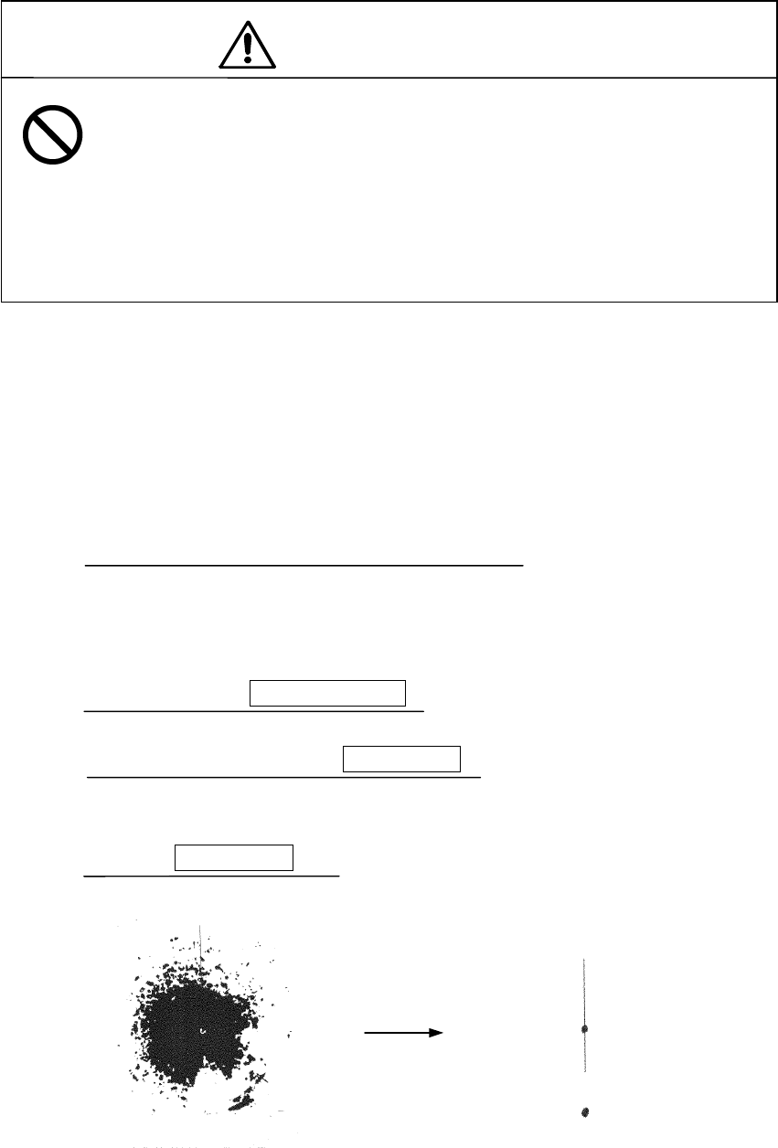
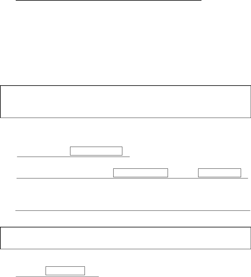
When sea waves become high, echoes from the high waves (sea clutter) appear on the
PPI screen making it difficult to see image of echoes from vessels or other objects. Sea
clutter is increasingly prominent to the extent that its source is close to the ship.
By using the [SEA] control function or the "automatic sea surface" function, sea surface
clutter may be suppressed facilitating monitoring of the targets.
Manual sea surface clutter suppression
Manual sea surface clutter suppressionManual sea surface clutter suppression
Manual sea surface clutter suppression
(a) Turn the [SEA] control in the clockwise direction.
As the control is turned in the clockwise direction, suppression of sea surface
clutter increases.
Automatic sea surface clutter suppression
Automatic sea surface clutter suppressionAutomatic sea surface clutter suppression
Automatic sea surface clutter suppression
(a) Push the soft key
PROCESS
PROCESSPROCESS
PROCESS
.
(b) Push the soft key 1 to select
A-SEA
A-SEAA-SEA
A-SEA
.
Sea surface clutter suppression is enabled depend on the condition of the image.
(c) Push the
MENU
MENUMENU
MENU
key.
The soft key will return to the initial function display.
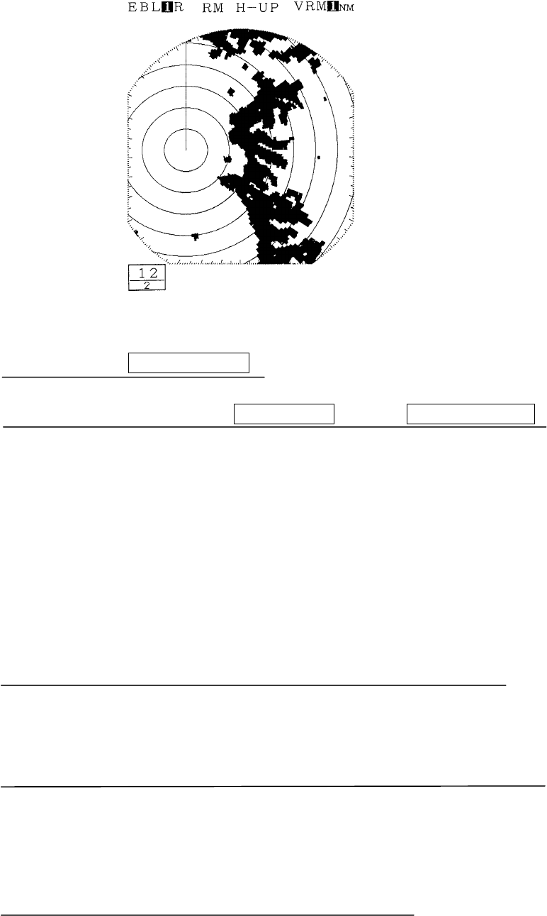
Sea clutter being displayed as
image due to high waves.
Sea clutter has been suppressed (the
image of the echo from the target has
also been suppressed).

175
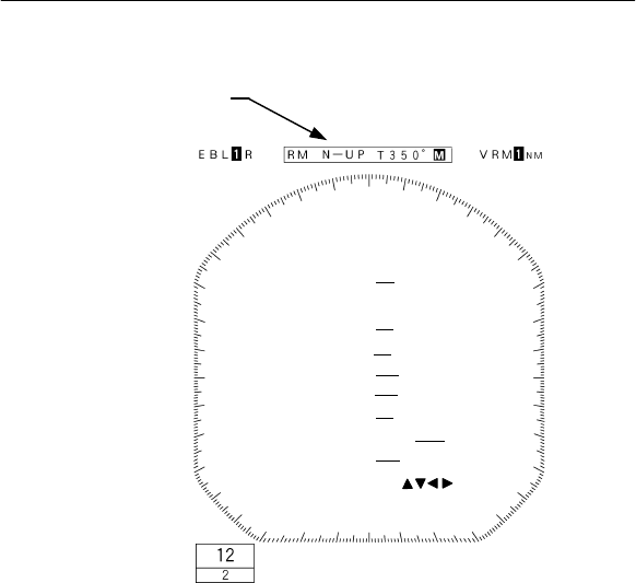
3.3.11 Measuring the range to the target
To measure the range to the target, the operator may take one of the following actions.
• Use VRM (Variable Range Markers)
• Move the center of the VRM (floating EBL)
• Use the parallel line cursor
• Use the cursor
1. Using VRM
1. Using VRM1. Using VRM
1. Using VRM
• A VRM is a circle that is displayed on the PPI screen.
• Since the size of the VRM may be change at will using the upper or lower portion
of the cross key, the operator is able to measure the range of any desired target.
• This radar equipment is capable of displaying two VRM simultaneously (#1VRM
and #2VRM).
• The #1VRM and #2VRM are displayed, selected and erased using the
VRM
VRMVRM
VRM
key.
• Whether or not the #2VRM is enabled is set at the menu.
• A VRM can take on the following states:
The VRM is not displayed.
The VRM is displayed
The cross key is not in VRM mode.
The cross key is in VRM mode
The VRM to be used (#1VRM or #2VRM) is not selected.
The VRM to be used (#1VRM or #2VRM) is selected.
Measuring the distance from the ship using #1VRM
Measuring the distance from the ship using #1VRMMeasuring the distance from the ship using #1VRM
Measuring the distance from the ship using #1VRM
(a) Select "FIX" in the line "EBL1/VRM1" - the menu "FUNCTION".
The #1VRM value represents the distance from the ship.
The center of #2VRM is always fixed at the position of the ship.
Setting whether or not use of #2VRM is enabled
Setting whether or not use of #2VRM is enabledSetting whether or not use of #2VRM is enabled
Setting whether or not use of #2VRM is enabled
(a) Select "YES" in the line "VRM2" - the menu "FUNCTION".
Use of #2VRM will be enabled.
If "NO" is selected, use of #2VRM will be disabled.
Operating the #1VRM/#2
Operating the #1VRM/#2Operating the #1VRM/#2
Operating the #1VRM/#2VRM
VRMVRM
VRM
(a) Push the VRM
VRMVRM
VRM key.
Each time the VRM key is pushed, the VRM that may be operated using the cross
key changes sequentially between #1VRM and #2VRM.
The #1VRM/#2VRM that is currently enabled is the VRM value at the upper left
of the screen that is enclosed with dotted lines.
176
(b) Push the left or right side of the cross key.
This enables operating the VRM selected in (a).
• When the lower portion of the cross key is pushed, the size of the VRM will be
reduced.
• When the upper portion of the cross key is pushed, the size of the VRM will be
increased.
Erasing the #1VRM and #2VRM
Erasing the #1VRM and #2VRMErasing the #1VRM and #2VRM
Erasing the #1VRM and #2VRM
(a) Push the VRM
VRMVRM
VRM key.
• When both #1VRM and #2VRM are displayed.
Push the VRM key and enclose the value of the #1VRM or #2VRM that is to
remain on the screen with dotted lines.
• When either #1VRM or #2VRM is displayed.
Enclose the displayed #1VRM or #2VRM in dotted lines.
(b) Continue pushing the VRM
VRMVRM
VRM key.
The #1VRM or #2VRM selected in (a) will be erased.
2. Moving the center of the VRM
2. Moving the center of the VRM2. Moving the center of the VRM
2. Moving the center of the VRM
Please refer to "3.3.14 Floating VRM and EBL" for the method of using the
floating EBL.
3. Changing the interval between the pa
3. Changing the interval between the pa3. Changing the interval between the pa
3. Changing the interval between the parallel line cursors
rallel line cursorsrallel line cursors
rallel line cursors
Please refer to "3.3.15 Using the parallel line cursor" for the method of using the
parallel line cursor.
4. Using the cross hair cursor
4. Using the cross hair cursor4. Using the cross hair cursor
4. Using the cross hair cursor
Please refer to "3.3.18 Simultaneously measuring the bearing, distance, and
travel time to the target" for the method of using the cross hair cursor.

177
3.3.12 Changing the range unit
With this radar equipment, the range unit measured using the VRM or cross hair cur-
sor may be selected from among the following.
NM (nautical miles)
KM (kilometers)
KY (kilo yards)
(a) Select among "NM", "KY", or "KM" in the line "RANGE" - the menu "DISPLAY".
(b) Push the MENU
MENUMENU
MENU key.
The menu setting has been completed.
3.3.13 Measuring the bearing of a target
To measure the bearing of a target, the operator may select one of the following actions.
• Use EBL (electronic cursor)
• Move and use EBL (floating EBL)
• Use the parallel line cursor
• Use the cursor
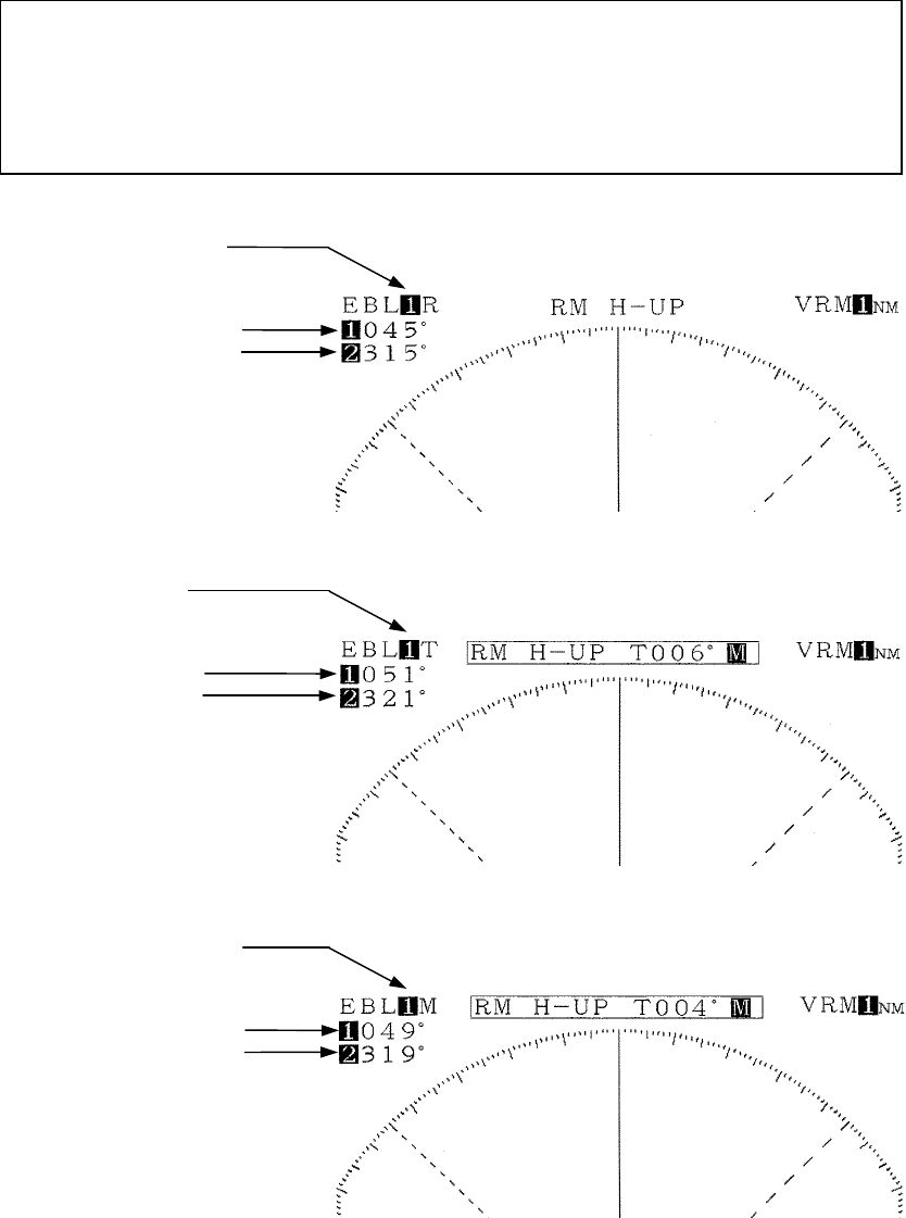
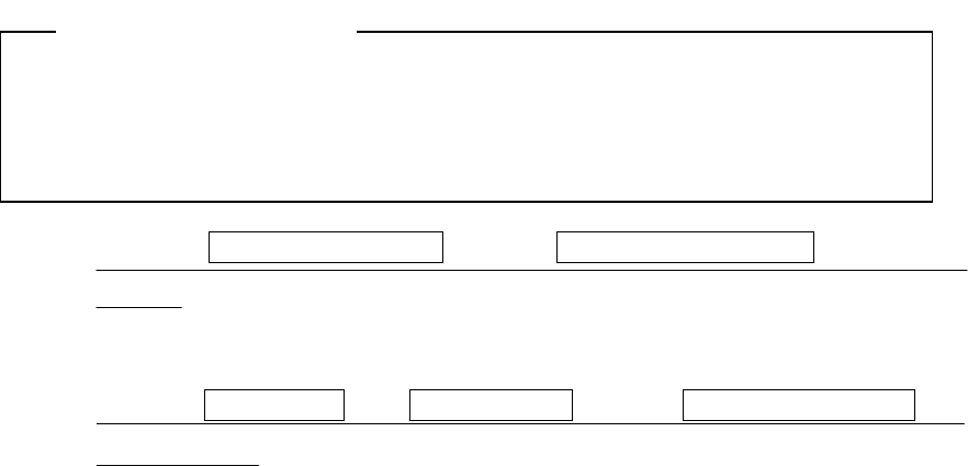
There are three modes in displaying the EBL bearing
• Relative bearing display : R
• True bearing display : T
• Magnetic bearing display : M
For details on display of bearing, please refer to "3.3.16 Switching the EBL and
cursor bearing display among relative, true and magnetic bearing display
mode".

178
1. Using EBL
1. Using EBL1. Using EBL
1. Using EBL
• An EBL is a straight line that is displayed on the PPI screen.
• Since the bearing of an EBL can be changed at will using the left and right por-
tion of the cross key, the operator is able to measure the bearing of any desired
target.
• This radar equipment is capable of displaying 2 lines of EBL simultaneously
(#1EBL, #2EBL).
• The #1EBL and #2EBL are displayed, selected and erased using
the
EBL
EBLEBL
EBL
key.
• Whether or not the #2EBL is enabled is set at the menu.
• An EBL can take on the following states:
The EBL is not displayed.
The EBL is displayed
The cross key is not in EBL mode.
The cross key is in EBL mode
The EBL to be used (#1EBL or #2EBL) is not selected.
The EBL to be used (#1EBL or #2EBL) is selected.
Measuring the distance from the ship using #1EBL
Measuring the distance from the ship using #1EBLMeasuring the distance from the ship using #1EBL
Measuring the distance from the ship using #1EBL
(a) Select "FIX" in the line "EBL1/VRM1" - the menu "FUNCTION".
The #1EBL value represents the bearing of the target with the ship as point of
reference.
The point of reference of #2EBL is always fixed at the position of the ship.
Setting whether or not use of #2EBL is enabled
Setting whether or not use of #2EBL is enabledSetting whether or not use of #2EBL is enabled
Setting whether or not use of #2EBL is enabled
(a) Select "YES" in the line "EBL2" - the menu "FUNCTION".
Use of #2EBL will be enabled.
If "NO" is selected, use of #2EBL will be disabled.
Operating the #1VRM/#2VRM
Operating the #1VRM/#2VRMOperating the #1VRM/#2VRM
Operating the #1VRM/#2VRM
(a) Push the EBL
EBLEBL
EBL key.
Each time the EBL key is pushed, the EBL that may be operated using the cross
key changes sequentially between #1EBL and #2EBL.
The #1EBL/#2EBL that is currently enabled is the EBL value at the upper left of
the screen that is enclosed with dotted lines.
(b) Push the left or right side of the cross key.
This enables operating the EBL selected in (a).
• When the left side of the cross key is pushed, the EBL rotates in the counter-
clockwise direction.
179
• When the right portion of the cross key is pushed, the EBL rotates in the
clockwise direction.
Erasing the #1EBL and #2EBL
Erasing the #1EBL and #2EBLErasing the #1EBL and #2EBL
Erasing the #1EBL and #2EBL
(a) Push the EBL
EBLEBL
EBL key.
• When both #1EBL and #2EBL are displayed.
Push the EBL switch and enclose the value of the #1EBL or #2EBL that is to
remain on the screen with dotted liens
• When either #1EBL or #2EBL is displayed.
Enclose the displayed #1EBL or #2EBL in dotted lines.
(b) Continue pushing the EBL
EBLEBL
EBL key.
The #1EBL or #2EBL selected in (a) will be erased.
2. Moving the center of the EBL
2. Moving the center of the EBL2. Moving the center of the EBL
2. Moving the center of the EBL
Please refer to "3.3.14 Floating VRM and EBL" for the method of using the free
floating EBL.
3. Changing the interval between
3. Changing the interval between3. Changing the interval between
3. Changing the interval between the parallel line cursors
the parallel line cursors the parallel line cursors
the parallel line cursors
Please refer to "3.3.15 Using the parallel line cursor" for the method of using the
parallel line cursor.
4. Using the cross hair cursor
4. Using the cross hair cursor4. Using the cross hair cursor
4. Using the cross hair cursor
Please refer to "3.3.18 Simultaneously measuring the bearing, distance and
travel time to target" for the method of using the cross hair cursor.
180
3.3.14 Floating VRM and EBL
Use the floating EBL function to move a VRM or an EBL.
Only #1EBL and #1VRM may be moved.
Setting the #1EBL and #1VRM to enable moving
Setting the #1EBL and #1VRM to enable movingSetting the #1EBL and #1VRM to enable moving
Setting the #1EBL and #1VRM to enable moving
(a) Select "FLOAT" in the line "EBL1/VRM1" - the menu "FUNCTION".
The point of reference of #1EBL and center of #1VRM is now movable.
However, the location of the point of reference of #1EBL and the center of #1VRM
is always at the same position.
Setting the point of reference and cent
Setting the point of reference and centSetting the point of reference and cent
Setting the point of reference and center position
er positioner position
er position
(a) Push the EBL
EBLEBL
EBL key or the VRM
VRMVRM
VRM key.
The cross key will become the floating EBL or floating VRM.
The position information on the mark displayed by the marker is displayed at the
lower right of the screen.
The marker information is displayed only until the point of reference and center
positions are determined.
(b) Use the cross key and push the ENTER
ENTERENTER
ENTER key.
The set marker position will be determined as the point of reference of #1EBL and
center of #1VRM.
Operating the EBL and VRM
Operating the EBL and VRMOperating the EBL and VRM
Operating the EBL and VRM
The method of operation is the same as for normal EBL and VRM.
• Only "setting the point of reference/ center position" is operable and if the EBL
key had been pushed, the operation is only with #1EBL while if the VRM key
had been pushed, the operation is only with #1VRM.
• The point of reference and center position may be moved only for #1VRM and
#1EBL. Prior to operation, be sure to select either #1EBL or #1VRM.
Please refer to "3.3.11 Measuring the range to the target" - "1. Using VRM",
"3.3.13 Measuring the bearing of a target" - "1. Using EBL"
Canceling the point of reference or center position
Canceling the point of reference or center positionCanceling the point of reference or center position
Canceling the point of reference or center position
(a) Select "FIX" in the line "EBL1/VRM1" - the menu "FUNCTION".
The floating EBL will be canceled and the point of reference and center position
will be fixed to the location of the ship.
181
3.3.15 Using the parallel line cursor
The parallel line cursor function is set to #1EBL and #1VRM
The parallel line cursor function is set to #1EBL and #1VRMThe parallel line cursor function is set to #1EBL and #1VRM
The parallel line cursor function is set to #1EBL and #1VRM
(a)
Select "PLINE 1" or "PLINE 2" in the line "EBL1/VRM1" - the menu "FUNCTION".
When setting to PLINE 1, the parallel line cursor is displayed in half circumference.
When setting to PLINE 2, the parallel line cursor is displayed in a full circumference.
Operating the parallel line cursor
Operating the parallel line cursorOperating the parallel line cursor
Operating the parallel line cursor
(a) Push the EBL
EBLEBL
EBL key or the VRM
VRMVRM
VRM key.
Depending on the setting at the line "EBL1/EBL2" of the menu "FUNCTION", the
parallel line cursor will be displayed in a half circumference or full circumference.
However, it is necessary to set #1EBL or #1VRM to operational mode using the
cross key.
(b) Set the bearing and interval of the parallel line cursor by operating the cross key
in the up-down and left-right directions.
• When the upper portion of the cross key is pushed, the interval increases.
• When the lower portion of the cross key is pushed, the interval decreases.
• When the left side of the cross key is pushed, the parallel cursor turns in the
counterclockwise direction.
• When the right side of the cross key is pushed, the parallel cursor turns in the
clockwise direction.
Canceling the parallel line cursor
Canceling the parallel line cursorCanceling the parallel line cursor
Canceling the parallel line cursor
(a) Select "FIX" in the line "EBL1/VRM1" - the menu "FUNCTION".
The parallel line cursor display is canceled and use of normal #1EBL and #1VRM
will be enabled.
3.3.16 Switching the EBL and cursor bearing display among relative, true and
magnetic bearing display mode
There are three methods of displaying the bearing using EBL and the cursor.
• Relative bearing display:
This is the bearing of an EBL or cursor displayed with the bearing of the ship's
bow (ship's heading marker) taken as 0 degrees.
• True bearing display(Note):
This is the bearing of an EBL or cursor displayed with the bearing of true north
(north pole) taken as 0 degrees.
182
• Magnetic bearing display:
This is the bearing of an EBL or cursor displayed with the north indicated by a
magnetic compass taken as 0 degrees.
(Note): The term "true bearing" and the terms "gyro bearing" or "gyrocompass
bearing" used hereafter shall have the same meaning.
In order to display the true bearing or magnetic bearing, it is necessary to input the
bearing information to the display.
Please refer to "3.6.1 Obtaining information on bearing" with respect to bearing in-
formation.
R: EBL relative bearing display
Relative azimuth angle of #1EBL
Relative azimuth angle of #2EBL
T: EBL true bearing display
True azimuth angle of #1EBL
True azimuth angle of #2EBL
M: EBL magnetic bearing display
Magnetic azimuth angle of #1EBL
Magnetic azimuth angle of #2EBL
183
Selection of bearing criteria (magnetic bearing, gyrocompass bearing)
Selection of bearing criteria (magnetic bearing, gyrocompass bearing)Selection of bearing criteria (magnetic bearing, gyrocompass bearing)
Selection of bearing criteria (magnetic bearing, gyrocompass bearing)
Select the bearing criteria as follows.
When the connected device a magnetic compass: MAG
When the connected device is a gyrocompass: TRUE
When GPS or LORAN is connected and the display mode does not become the true
bearing display mode even when (a) has been undertaken, switch to the other bearing
criterion.
(a) Select "MAG" or "TRUE" in the line "BEARING" - the menu "RADAR SET-UP 1".
(b) Push the MENU
MENUMENU
MENU key.
The menu setting has been completed.
Selection of the bearing criteria
Selection of the bearing criteriaSelection of the bearing criteria
Selection of the bearing criteria
(a) Select "REL" or "TRUE, MAG" in the line "EBL READOUT" - the menu "FUNC-
TION".
• When "REL" is selected, the bearing of the EBL when the ship's bow (ship's
heading marker) bears to 0 degrees is displayed.
• When "TRUE, MAG" is selected, the bearing of the EBL when the device se-
lected under "BEARING" above detects "north" is assumed to be 0 degrees is
displayed.
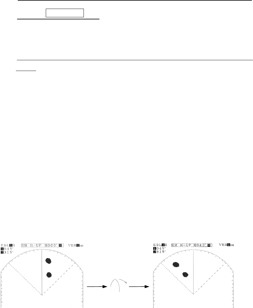
3.3.17 Changing the bearing display method of the PPI screen
The methods of display of the radar PPI screen consist of the following.
•
Relative bearing display (head-up display)
The ship's bow is displayed directly at the top of the PPI screen (bearing scale 0 degrees).
When the bearing of the ship's bow changes, the bearing of the echo image on the
PPI screen also changes.
When bearing information cannot be obtained from such navigation devices as
gyrocompass, display is by this relative bearing method.
The PPI image rotates counterclockwise
The ship rotates
in the starboard direction
184
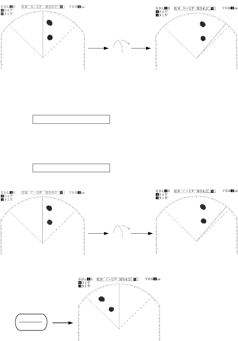
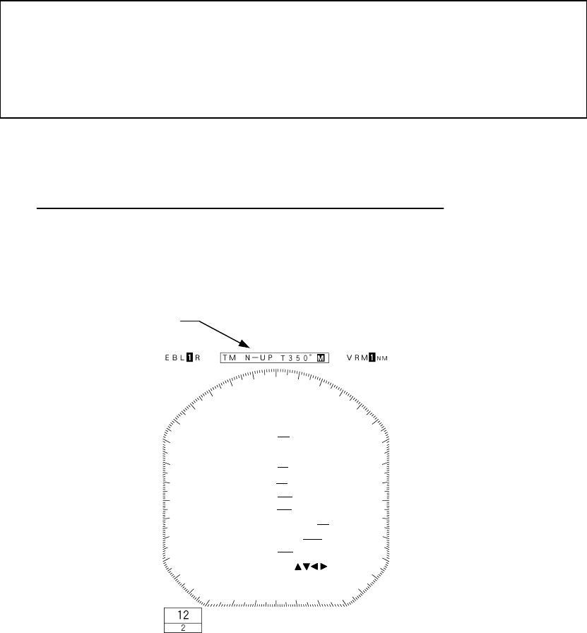
• True bearing display (north-up display)
"North" is displayed as direct north of the PPI screen.
Even when the bearing of the ship's bow changes, the bearing of the PPI image
does not change.
(Gyrocompass or other device that provides bearing information is required.)
• Course-up display
The bearing of the ship's bow is always directly at the top of the PPI screen when
the BRIL/HL
BRIL/HLBRIL/HL
BRIL/HL
OFF
OFFOFF
OFF key is continuously pushed (course setting).
Even when the bearing of the ship's bow changes, the bearing of the echo image
on the PPI screen does not change and the ship's heading marker rotates to the
extent of the change in the bearing of the ship's bow.
When the heading changes significantly, the course should be reset by pushing
the BRIL/HL
BRIL/HLBRIL/HL
BRIL/HL
OFF
OFFOFF
OFF key continuously.
(Gyrocompass or other device that provides bearing information is required.)
The ship's heading marker
rotates clockwise.
The ship rotates
in the starboard direction
The ship's heading marker
rotates clockwise.
The ship rotates
in the starboard direction
BRIL
HL OFF

185
In order to change the method of bearing display on the PPI screen, it is necessary
to input the bearing information from a navigation device.
Please refer to "3.6.1 Obtaining information on bearing" with respect to bearing
display.
Course setting in course
Course setting in courseCourse setting in course
Course setting in course-
--
-up mode
up modeup mode
up mode
(a) Continue to hold down the BRIL/HL
BRIL/HLBRIL/HL
BRIL/HL
OFF
OFFOFF
OFF
key.
The course will be set at the top of the PPI screen.
3.3.18 Simultaneously measuring the bearing, distance and travel time to the target
The cursor function is used for this measurement.
The cursor that is used here is indicated by a "+" mark on the PPI screen.
By using this function, in addition to the distance to the cursor, the bearing and travel
time to the cursor position may be obtained.
In order to obtain the travel time, it is necessary to input the ship's speed information
from a navigation device.
Please refer to "3.6.2 Obtaining information on speed".
186
Displaying the cursor
Displaying the cursorDisplaying the cursor
Displaying the cursor
(a) Push the soft key DISPLAY
DISPLAYDISPLAY
DISPLAY
.
(b) Push the soft key 4 and select CUR
CURCUR
CUR
ON
ONON
ON
.
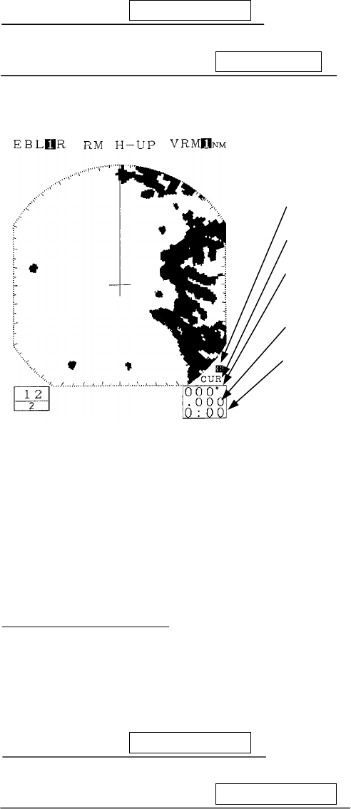
Information will be shown as follows at the lower right of the screen.
• When information on speed is input, the maximum travel time displayed is
"9:59".
• The cursor will appear on the PPI screen and the cross key will enter cursor
mode.
Moving the cursor
Moving the cursorMoving the cursor
Moving the cursor
(a) Operating the cross key.
When cursor movement is abandoned, the bearing and distance to that point and
the required travel time to that point are displayed.
Erasing the cursor
Erasing the cursorErasing the cursor
Erasing the cursor
(a) Push the soft key DISPLAY
DISPLAYDISPLAY
DISPLAY
.
(b) Push the soft key 4 and select CUR
CURCUR
CUR
OFF
OFFOFF
OFF .
The cursor, bearing, distance and required travel time will be erased.
The cross key is in cursor mode.
The cursor function is operating.
Azimuth angle from the bearing of the
ship's bow to the cursor.
Distance from the ship to the cursor.
Travel time when traveling from the
ship's position to the cursor position.

187
3.3.19 L/L display of the cursor
In order to use this function, it is necessary to input the ship's position information
from a navigation device.
Please refer to "3.6.3 Obtaining information on position " with respect to informa-
tion on the ship's position.
Select "TRUE" in the line "BEARING" - the menu "RADAR SET-UP 1".
If the setting is "MAG" and information for converting magnetic bearing values into
gyro bearing values is input from a navigation device, L/L display will be under-
taken but when such conversion is not possible, such display will not be made as
errors will be generated in the L/L value.
3.3.20 Magnifying the echo images on the PPI screen
The following methods may be used to magnify the echo images that are shown on the
PPI screen.
• Use the image expansion function
• Set the transmission pulse width wider
• Use the zoom function
1. Using the image expansion func
1. Using the image expansion func1. Using the image expansion func
1. Using the image expansion function
tiontion
tion
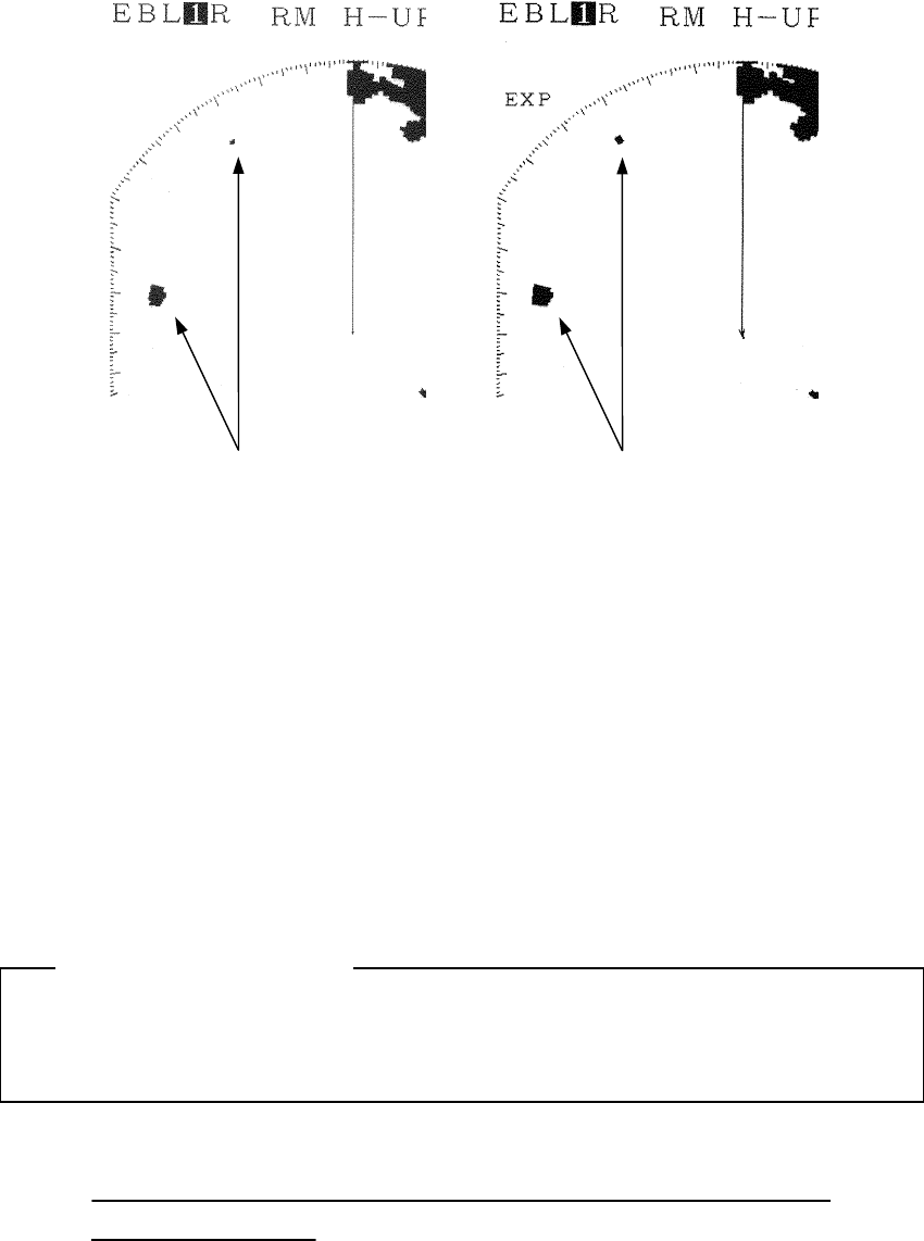
The expansion function enlarges the echo images on the PPI screen in the angle direc-
tion and distance direction.
When the image expansion function is used, two targets that are in close proximity
in the range direction (depth) and angle direction may be shown as one image on
the PPI screen.
(a) Push the soft key DISPLAY
DISPLAYDISPLAY
DISPLAY
.
(b) Push soft key 1 and select EXP
EXPEXP
EXP
ON.
ON.ON.
ON. .
Attention
188
2. Changing the transmission pulse width
2. Changing the transmission pulse width2. Changing the transmission pulse width
2. Changing the transmission pulse width
With respect to ranges of 1.5 NM, 3 NM and 6 NM, the transmission pulse width may
be changed.
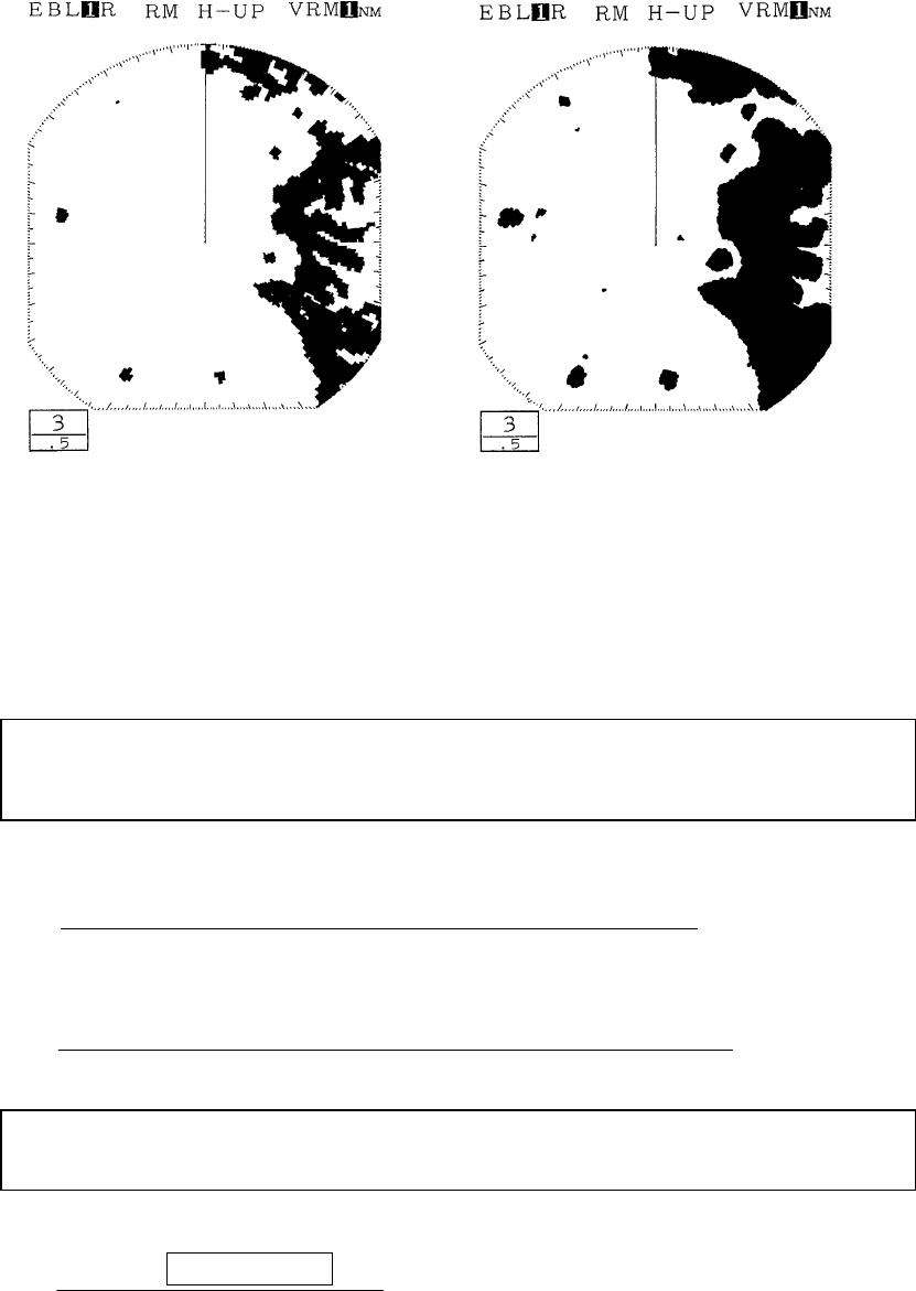
If a wider pulse width is selected, the echo images on the PPI screen will be extended in
the range direction. Conversely, when a narrower pulse width is selected, the image is
compressed (made shorter) in the range direction.
The difference of this function from the image expansion function is that when the
pulse width becomes wider, echoes that had not been visible are sometimes visible as
images.
When switching to a wide pulse width, two targets that are in proximity in the range
direction (depth) may be shown as one echo on the PPI screen.
(a) Select "1.5NM", "3NM", or "6NM" in the line "TX PULSE" - the menu
"RADAR SET-UP 1".
Before magnified After magnified
Attention
189
3. Using the zoom function
3. Using the zoom function3. Using the zoom function
3. Using the zoom function
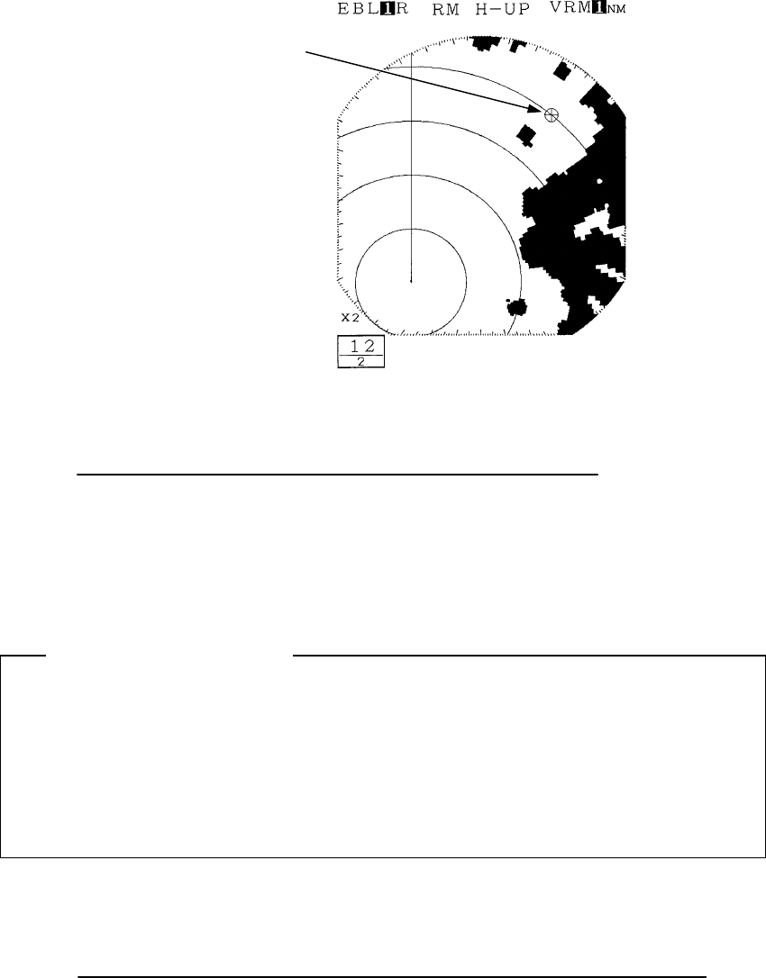
The zoom function allows any given area on the PPI screen to be enlarged by a factor of two.
The area to be enlarged is designated using the marker.
zThis function is disabled when the 0.125NM range is in use or TM is in use or the
floating EBL function is active.
Setting the zoom area
Setting the zoom areaSetting the zoom area
Setting the zoom area
(a) Select "SET" in the line "ZOOM" - the menu "FUNCTION".
The marker "+" will appear on the PPI screen.
(b) Position the marker in the desired location using the cross key.
zThe marker can be moved within up to 66% of the monitoring range.
(c) Push the ENTER
ENTERENTER
ENTER key.
The area with the marker at the center will be enlarged by a factor of two.
After magnified (wider pulse width)
Before magnified (narrow pulse width)
190
Canceling the zoom
Canceling the zoomCanceling the zoom
Canceling the zoom
(a) Select "OFF" in the line "ZOOM" - the menu "FUNCTION".
The zoom function will be canceled.
3.3.21 Reducing unnecessary noise and emphasizing the target
Do not use this function when observing radar beacon, SART signal or a target
that moves at high speed across the radar screen.
This function is optimized in TM mode.
When using this function in RM mode, please use N-UP or C-UP. If used with
H-UP, the image may blur.
Set the image processing
Set the image processingSet the image processing
Set the image processing
(a) Select "PR1" or "PR2" in the line "PROCESS" - the menu "FUNCTION".
• PR1: This is used when there is a target that is moving at low speed.
Images of relatively unstable targets are emphasized and displayed in a
stable manner.
This function has the effect of suppressing irregular signals such as sea
surface clutter.
However, images of targets that are moving at high speed will become weak.
As a rule of thumb, the function should be used at ranges of 1.5NM or less.
Location designated by the marker
Attention
191
x PR2: This function is used in stabilizing unstable images using PR1.
This function is effective when sea surface clutter is abundant.
As a rule of thumb, the function should be used at ranges of 3NM or more.
Canceling image processin
Canceling image processinCanceling image processin
Canceling image processing
gg
g
(a) Select "OFF" in the line "PROCESS" - the menu "FUNCTION".
The image processing function has been canceled.
3.3.22 Moving the center of the PPI screen
By moving the center of the PPI screen (relocating the center), it is possible to extend
the range in any given direction.
z
This function is disabled when the zoom function is enabled or the maximum Range
is in use.
Setting the position to which the center is relocated.
Setting the position to which the center is relocated.Setting the position to which the center is relocated.
Setting the position to which the center is relocated.
(a) Push the soft key DISPLAY
DISPLAYDISPLAY
DISPLAY
.
(b)
Push the soft key 2 and select first
OFF
OFFOFF
OFF
CENT
CENTCENT
CENT
and then
CENTER
CENTERCENTER
CENTER
.
The marker will be displayed on PPI screen.
(c) Use the cross key to position the marker at the center of the desired PPI screen.
z
The marker may be moved up to within 66% of the monitoring range.
(d) Push the ENTER
ENTERENTER
ENTER
key.
The center of the PPI screen will move to the designated location.
192
Canceling center relocation
Canceling center relocationCanceling center relocation
Canceling center relocation
(a) Push the soft key DISPLAY
DISPLAYDISPLAY
DISPLAY
.
(b)
Push the soft key 2 and select first
CENTER
CENTERCENTER
CENTER
and then
O
OO
OFF
FFFF
FF
CENT
CENTCENT
CENT
.
Center relocation has been canceled.
3.3.23 Controlling power consumption of the radar
In order to control power consumption, the timed transmission function is used.
By using the timed transmission function, the system repeatedly alternates between
transmission mode and standby mode.
Setting the transmission time
Setting the transmission timeSetting the transmission time
Setting the transmission time
(a) Select "10", "20", or "30" in the line "TX PERIOD" - the menu "DISPLAY".
The transmission time is designated by the rotation of the scanner unit.
Setting the standby time
Setting the standby timeSetting the standby time
Setting the standby time
(b) Select "3", "5", "10", or "15" in the line "STBY PERIOD" - the menu "DISPLAY".
The standby time is designated as 3 minutes, 5 minutes, 10 minutes or 15
minutes.
Commencing timed transmission
Commencing timed transmissionCommencing timed transmission
Commencing timed transmission
(c) Select "ON" in the line "TIMED TX" - the menu "DISPLAY".
When this is undertaken, timed transmission begins.
193
(d) Push the
MENU
MENUMENU
MENU
key.
The menu setting has been completed.
1. After transmitting to the extent of the number of rotations of the scanner unit
designated, the system enters the standby mode for the period designated.
During standby mode, the echo from the radar disappears from the screen and
a timer that shows the remaining time to the next transmission is shown on
the display.
2. After completion of the standby period, the system again transmits to the ex-
tent of the designated number of rotations of the scanner unit.
3. This process is repeated.
CAUTION
While timed transmission is in progress, under no circumstances should the
scanner unit be approached.
While the scanner unit is stopped during the standby period, after completion
of such standby period, the scanner unit will resume rotation and may collide
with the body and cause injury.
Canceling timed transmission
Canceling timed transmissionCanceling timed transmission
Canceling timed transmission
(e) Select "OFF" in the line "TIMED TX" - the menu "DISPLAY".
The timed transmission has been canceled.
(f) Push the MENU
MENUMENU
MENU key.
The menu setting has been completed.
Canceling timed transmission while in standby mode
Canceling timed transmission while in standby modeCanceling timed transmission while in standby mode
Canceling timed transmission while in standby mode
(g) Push the STBY
STBYSTBY
STBY key.
The timed transmission mode will be canceled and the system will return to
normal standby mode.
194
3.3.24 Locking a fixed target on the radar PPI screen while the ship is navigating
Normally, the PPI image moves as the ship moves.
This method of display is called:
Relative Motion : RM
In contrast to this, the display mode in which the echo images from fixed targets such
as land do not move and the location of the ship (center of the PPI) moves according to the
course and speed of the ship is called:
True Motion : TM
In order to undertake TM display, it is necessary to input bearing information and the
ship's speed information from a navigation device.
Please refer to "3.6.1 Obtaining information on bearing" and "3.6.2 Obtaining in-
formation on speed" with respect to information on bearing and on speed.
Commencing True Motion display
Commencing True Motion displayCommencing True Motion display
Commencing True Motion display
(a) Select "TM" in the line "TM/RM" - the menu "FUNCTION".
The motion display on the PPI screen will change to "TM".
• The bearing display with TM is enabled is only N-UP.
True Motion Display mode: TM
FUNCTION
EBL1/EBL2
EBL2
VRM2
EBL READOUT
ZOOM
TM/RM
HDG MODE
PROCESS
FIX FLOAT
PLINE1 PLINE2
NO YES
NO YES
REL TRUE,MAG
OFF SET
RM TM
H-UP N-UP C-UP
SELECT W/CROSS KEY' ( )
PRESS ENT TO SET
PRESS MUNU TO RETURN
OFF PR1 PR2
195
Canceling true motion display
Canceling true motion displayCanceling true motion display
Canceling true motion display
(a) Select "RM" in the line "TM/RM" - the menu "FUNCTION".
The TM is canceled and the mode is now N-UP of RM.
Relative Motion Display mode: RM
FUNCTION
EBL1/EBL2
EBL2
VRM2
EBL READOUT
ZOOM
TM/RM
HDG MODE
PROCESS
FIX FLOAT
PLINE1 PLINE2
NO YES
NO YES
REL TRUE,MAG
OFF SET
RM TM
H-UP N-UP C-UP
SELECT W/CROSS KEY' ( )
PRESS ENT TO SET
PRESS MUNU TO RETURN
OFF PR1 PR2
196
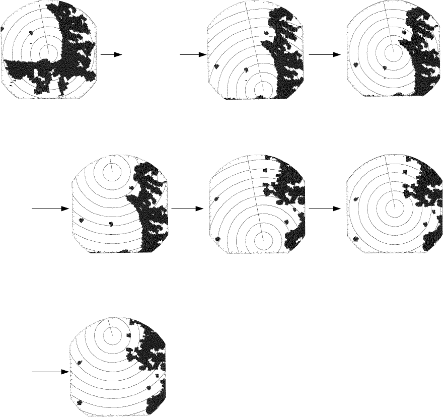
• The following is an example of switching from relative motion display (RM) to
true motion display (TM)
The center of the PPI
moves to a location within
66% of the radius.
The center of the PPI
moves together with the
movement of the ship.
When the center of the PPI moves to a lo-
cation within 66% of the radius, the cente
r
of the PPI automatically resumes move-
ment to a location 66% of the radius in the
diagonal direction.
Select "TM"
Relative motion display

197
3.3.25 Monitoring the motion of other ships (Targets)
One of the following functions is used to monitor the movement of other ships (targets)
• Wakes (set using the soft key)
• Lookout alarm (set using the soft key)
1. Radar display of wake
1. Radar display of wake1. Radar display of wake
1. Radar display of wake
It is possible to confirm the movement of other ships through the length and direction
of the wake and this can be utilized to avoid collisions.
The length of a wake may automatically be selected among 15 seconds, 30 seconds, 1
minute, 3 minutes, 6 minutes, 15 minutes, 30 minutes and continuous.
Commencing radar display of a wake
Commencing radar display of a wakeCommencing radar display of a wake
Commencing radar display of a wake
(a) Push the soft key
PROCESS
PROCESSPROCESS
PROCESS
.
(b) Push the soft key 4 and set the wake time to other than
WKS
WKSWKS
WKS
OFF
OFFOFF
OFF
.
Radar display of the wake will begin.
Ending radar display of a wake
Ending radar display of a wakeEnding radar display of a wake
Ending radar display of a wake
(a) Push the soft key
PROCESS
PROCESSPROCESS
PROCESS
.
(b) Push the soft key 4 and set the wake time to
WKS
WKSWKS
WKS
OFF
OFFOFF
OFF
.
Display of the wake will be discontinued.
2. Using the lookout alarm
2. Using the lookout alarm2. Using the lookout alarm
2. Using the lookout alarm
The guard zone may be defined using the lookout alarm.
The guard zone refers to an "area" defined on the PPI screen.
When a target enters this "area" or exits the "area" an alarm is sounded.
The alarm mode that is activated when a target enters a guard zone is called the IN
mode.
The alarm mode that is activated when a target exits a guard zone is called the OUT
mode.
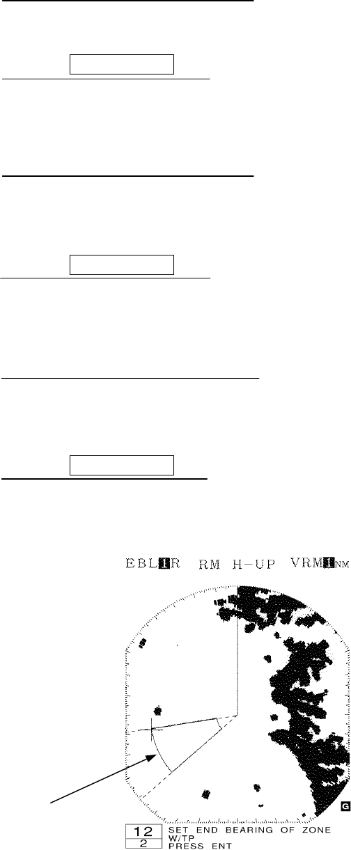
Setting the guard zone
Setting the guard zoneSetting the guard zone
Setting the guard zone
(a) Push the soft key GUARD
GUARDGUARD
GUARD
.
The marker "+" appears on the PPI screen and a dotted distance help line and
dotted azimuth help line that indicates the distance and azimuth of the marker will
be displayed.
(b) Push the soft key 1 MAKE
MAKEMAKE
MAKE
.
198
(c) Move the marker using the cross key.
Move the marker to the initial point of reference of the zone to be designated.
(d) Push the
ENTER
ENTERENTER
ENTER
key.
The initial point of reference of the guard zone has been designated.
The dotted distance help line and dotted azimuth help line have been fixed.
(e) Move the marker using the cross key.
Move the marker to the distance range of the guard zone to be designated.
A new dotted distance help line will be displayed.
(f) Push the
ENTER
ENTERENTER
ENTER
key.
The distance of the guard zone has been set.
A ring around the distance range will be displayed as a continuous line.
(g) Move the marker using the cross key.
Move the marker to change the shape of the guard zone to any desired shape.
The form will change in the manner of a fan opening (or closing).
(h) Push the
ENTER
ENTERENTER
ENTER
key.
The extremity of the guard zone has been designated and the process has been
completed.
Guard zone in the process
of being designated.
199
Changing the alarm mode
Changing the alarm modeChanging the alarm mode
Changing the alarm mode
(a) Push the soft key
GUARD
GUARDGUARD
GUARD
.
(b) Push the soft key 4 to switch the wake time between
ALM
ALMALM
ALM
IN
ININ
IN
and
ALM
ALMALM
ALM
OUT
OUTOUT
OUT
.
The selected alarm mode is activated.
Eradicating the guard zone
Eradicating the guard zoneEradicating the guard zone
Eradicating the guard zone
(a) Push the soft key
GUARD
GUARDGUARD
GUARD
.
(b) Push the soft key 2 to designate
ALM
ALMALM
ALM
OFF
OFFOFF
OFF
.
The guard zone that had been produced will disappear from the PPI screen and
the lookout alarm function will be disabled.
Calling a guard zone
Calling a guard zoneCalling a guard zone
Calling a guard zone
(a) Push the soft key
GUARD
GUARDGUARD
GUARD
.
(b) Push the soft key 2 to designate
ALM
ALMALM
ALM
ON
ONON
ON
.
The guard zone previously produced will be displayed on the PPI screen and the
lookout alarm function will be enabled.
Changing the sensit
Changing the sensitChanging the sensit
Changing the sensitivity of the alarm
ivity of the alarmivity of the alarm
ivity of the alarm
(a) Push the soft key
GUARD
GUARDGUARD
GUARD
.
(b) Push the soft key 3 repeatedly to select the alarm sensitivity.
Alarm sensitivity "1" through "7" indicates the level of the image (strength of the
echo) at which the alarm is sounded.
SENS
SENSSENS
SENS
1
11
1
most readily causes the alarm to sound while
SENS
SENSSENS
SENS
7
77
7
is
least sensitive.
The alarm may sound as a result of noise.
200
3.4 Other Convenient Functions
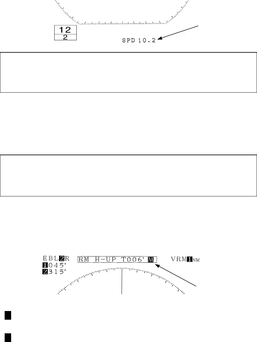
3.4.1 Displaying the ship's speed on the display unit
When speed information is input to the display unit, the ship's speed is automatically
displayed.
In order to use this function, it is necessary to input ship’s speed information from a
navigation device.
Please refer to "3.6.2 Obtaining information on speed".
3.4.2 Displaying the ship's heading on the display unit
When ship’s heading information is input to the display unit, the ship's heading is
automatically displayed.
In order to use this function, it is necessary to input ship’s bearing information from a
navigation device.
Please refer to "3.6.1 Obtaining information on bearing".
This radar equipment is capable of inputting bearing information from the following
two input connectors at the back of the display unit.
• CMPS+ and CMPS- terminals of the EXT1(J3) connector
• NAVRX and NAVCOM terminals of the GPS(J4) connector.
M
MM
M : Bearing information input from CMPS+ and CMPS- terminals of
the EXT1(J3) connector
L
LL
L : Bearing information input from NAVRX and NAVCOM terminals of
the GPS(J4) connector
Ship's speed
Input terminal display

201
The order of priority in utilizing bearing information is as follows.
M
MM
M L
LL
L
CMPS+, CMPS- terminals > NAVRX, NAVCOM terminals
(priority: high) (priority: low)
3.4.3 Displaying position information (latitude/longitude, LORAN C time difference) of
the ship and waypoint information (latitude/longitude)
Display of position in
Display of position inDisplay of position in
Display of position information
formationformation
formation
(a) Select among "L/L", "TD", "CUR L/L", or "WPT L/L" in the line "POSITION"
- the menu "DISPLAY".
When displaying latitude/longitude : "L/L"
When displaying LORAN C time difference : "TD"
When displaying L/L of the cursor : "CUR L/L"
When displaying the latitude and longitude of the waypoint
: "WPT L/L"
Erasing location information
Erasing location informationErasing location information
Erasing location information
(b) Select "NO" in the line "POSITION" - the menu "DISPLAY".
The location information is erased.
When "L/L" is selected, it is necessary to input the ship's position (latitude and lon-
gitude) information from a navigation device.
When "TD" is selected, it is necessary to input the ship's position (LORAN C time
difference) information is a navigation device.
When "CUR L/L" is selected, it is necessary to input the ship's position (latitude and
longitude) information from a navigation device.
When WPT "L/L" is selected, it is necessary to input the waypoint’s position (latitude
and longitude) information from a navigation device.
Please refer to "3.6.3 Obtaining information on position" for details.

202
3.4.4 Displaying the waypoint
In order to use this function, it is necessary to input of the following information to
the display unit:
Information on the bearing of the waypoint
Information on the distance to the waypoint
Information on the ship's speed.
Please refer to:
"3.6.1 Obtaining information on bearing"
"3.6.2 Obtaining information on speed"
"3.6.4 Obtaining information on the distance to the waypoint"
Display of the waypoint
Display of the waypointDisplay of the waypoint
Display of the waypoint
(a) Select "ON" in the line "WAYPOINT" - the menu "DISPLAY".
• The bearing, distance and required travel time (when ship speed information
has been input) will be displayed.
• The route from the ship to the waypoint will be displayed with the following
marker.
Circle : Position of the waypoint
Refer to "2.2 Explanation of Screen Readout"
Erasing the waypoint
Erasing the waypointErasing the waypoint
Erasing the waypoint
(a) Select "OFF" in the line "WAYPOINT" - the menu "DISPLAY".
The waypoint mark, the bearing, distance and required travel time to the
waypoint will disappear.

203
3.5 Miscellaneous Considerations
3.5.1 Replacing the battery (BT1)
In order to maintain the information that has been set, the battery (BT1) needs to be
replaced at regular intervals.
(a) Replacing the battery (BT1) [Type: CR2032-FT6-1, SANYO Electric Co, Ltd.]
• Please call the dealer servicing your locality for a replacement battery.
(b) Reinitializing
• The lithium battery maintains the content of the setting of the menu and soft
key even when the power is shut off allowing use under the conditions of the
last use.
• If this battery runs down, all conditions including the menu will automatically
be reset.
For this reason, initializing is required after replacement of the battery.
When the battery wears down, distance and bearing may become inaccurate.
In such cases, the battery should immediately be replaced and initialization un-
dertaken.
• In the event immediate replacement of the battery is not feasible, initializa-
tion should be undertaken each time the power is turned on as an emergency
measure. However, each time the power is shut off, the content that has
been set is reset.
Please refer to "9.8 Initial Setting" with respect to details on initialization.
Attention
204
3.5.2 In cases of abnormality during operations
In the event such phenomena as the screen becoming disturbed or the machine not
accepting switch input occurs during use of the radar, initialize using the procedures
outlined below.
When initialization is undertaken, all setting excluding the menu “INITIAL SET-
TING 1” and “INITIAL SETTING 2” will be reset and the ex-factory shipment con-
ditions.
(a) Push the STBY/OFF
STBY/OFFSTBY/OFF
STBY/OFF key and X-MIT/OFF
X-MIT/OFFX-MIT/OFF
X-MIT/OFF key simulta-
neously.
Power is turned off.
(b) Push the MENU
MENUMENU
MENU key, ENTER
ENTERENTER
ENTER key and STBY/OFF
STBY/OFFSTBY/OFF
STBY/OFF key
simultaneously.
Power will be turned on as in normal operation for turning on power.
Attention

205
3.6 External Navigation Devices
Please refer to "9.3.4 Display unit rear panel" on connections.
This radar equipment has the following busses at the rear of the display unit.
・NMEA
An external navigation device with either of these busses may be connected for input
and output of information.
3.6.1 Obtaining information on bearing
In order to obtain information on the bearing of the ship, one of the following needs to
be connected to the display unit.
• Magnet compass
• GPS gyro
Bearing information is input from either the CMPS or NAVRX terminals.
3.6.2 Obtaining information on speed
In order to obtain information on the speed of the ship, one of the following devices
need to be connected to the display unit.
• GPS
• LORAN C
Speed information is input from either the CMPS or NAVRX terminals.
3.6.3 Obtaining information on position
In order to obtain information on the ship's position in terms of latitude and longitude,
one of the following devices need to be connected to the display unit.
• GPS
• LORAN C
In order to obtain the ship's position information using LORAN C time difference, the
following needs to be connected to the display unit.
• LORAN C
CMPS+ and CMPS- terminals of the EXT1(J3) connector
NAVRX and NAVCOM terminals of the GPS(J4) connector
206
In order to obtain information on the L/L of the waypoint, one of the following devices
need to be connected to the display and the waypoint set in such device.
• GPS
• LORAN C
Information on position is input from either the CMPS or NAVRX terminals.
3.6.4 Obtaining information on distance to the waypoint
In order to obtain information on distance to the waypoint, one of the following devices
need to be connected to the display unit, and it is necessary that the waypoint set in the
navigation device is displayed on screen.
• GPS
• LORAN C
Information on distance is input from either the CMPS or NAVRX terminals.
207
4 How to Interpret the PPI Screen
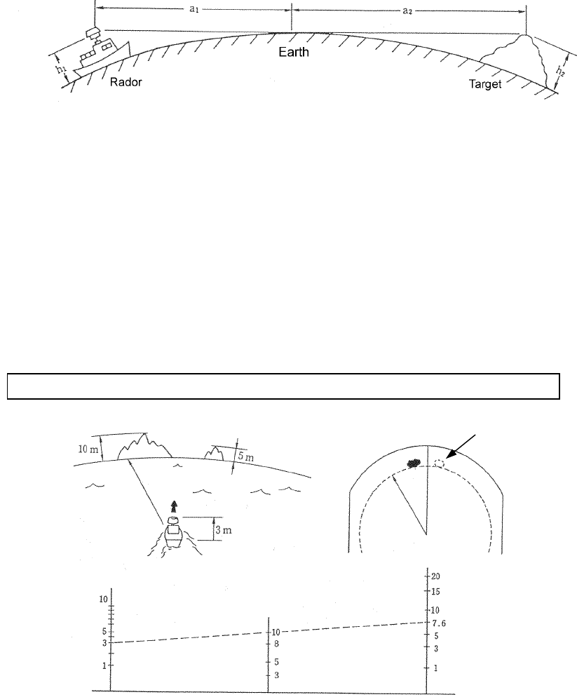
4.1 Height of and the Distance to the Target
The maximum distance to a target that can be observed with a radar depends not only on
the power of the radar's transmitter, beam width of the scanner unit, and the receiver's
sensitivity but also on height of a target, distance to a target and height of scanner unit line
etc. This is because the radio wave emitted by a radar runs straight, undergoing no
influence by the curvature of the earth surface.
[Distance and Target]
For example, when the scanner unit lies 3 meters above the sea level, the radar can
detect and display an island with a height of 10 meters at a distance 10 NM away from
the scanner unit position but cannot detect and display an island with a height of 5
meters at the same distance. This is theoretically true but does not always hold,
depending on weather conditions.
For a target located 10 NM away to be displayed on a radar, it theoretically needs to be
7.6 meters or higher. Any targets lower than 7.6 meters cannot be displayed on a radar.
The target may be unable to be observed when the height of a scanner unit or an target is low
.
a1=2.23√h1
a2=2.23√h2
a1 + a2=2.23 (√h1 + √h2 )
a1, a2:Unit [Nautical miles]
h1, h2:Unit [Meters]
Island not displayed on the screen
10 NM
a1+a2(NM)
Distance
h2(meters)
Target height
h1(meters)
Scanner unit height
10 NM
208
4.2 Returns from a Target
The intensity of returns from a target is related not only to the size of the target but
also to the materials and shape of the components making up the target. Accordingly,
larger objects do not necessarily develop strong returns.
On coastlines, in particular, the intensity of returns is dependent on their
physiographic features. For a coastline with a fairly gradual ascent, only inland
mountains areas may be displayed as echoes. This fact needs to be kept in mind when
measuring the distance to a coastline.
Since the echo which returns from a coastline with a fairly gradual ascent is weak,
observation of such land may not be able to be performed.
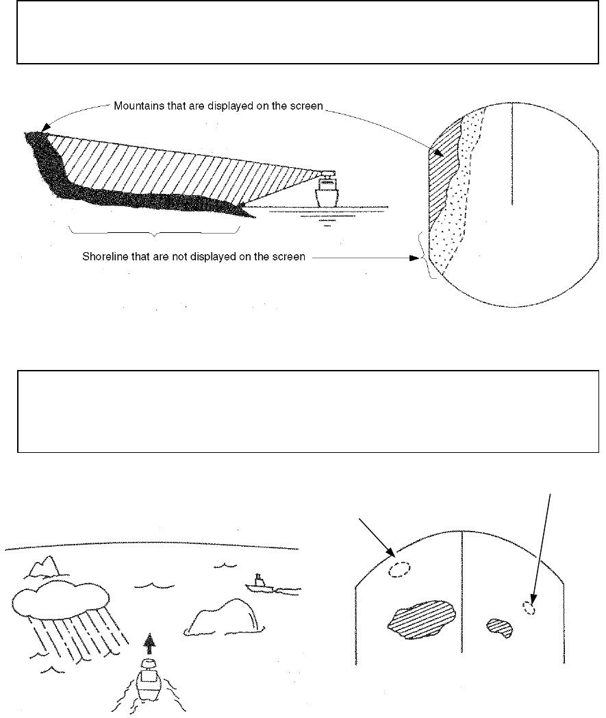
4.3 Propagation Path of Radio Waves
Radio waves may be shielded if there is a large intercepting obstacle (e.g.,
mountains, rain, snow, etc.) in their propagation path and any targets behind the
obstacle cannot be observed.
A
n island that is not displayed because of heav
y
rain in between the own ship and the island
A
ship that is not displayed because of an island
in between the own ship and the target ship
209
4.3.1 Sea returns
On a wavy sea surface, an echo appears on the PPI screen as a bright defused image at the
center of the screen. This echo is developed by returns from the sea surface. The features of
the echo depend on the size and range of the wave, and the wind direction.
4.3.2 False echoes
There are cases in which nonexistent targets appear as echoes or in which existing targets
do not appear as echoes on the PPI screen. These echoes are called false echoes.
False echoes are produced by the factors explained below.
Please observe carefully in consideration of there being always false echoes.
(a) Ghost
Depending on the location where the scanner unit is installed, radio waves are emitted from nearby
chimney stacks or masts, developing ghosts. Consequently, targets that are located in those direction
may not appear as echoes on the PPI screen.
The presence of these ghosts can be identified by observing sea returns and checking the returns for
dim areas or voids.
If a ghost is detected, remember the direction in which it appears and observe the target carefully.
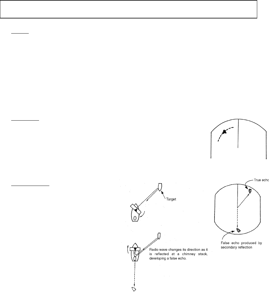
(b) Side echo
There are cases in which an arc-shaped broken line appears over
the same range as the echo from the target. This image is caused by
the side lobes of the beam emitted from the scanner unit. This type
of false echoes can easily be identified if the target stands alone.
(c) Indirect echo
The direction of the radio wave
from the radar may be changed by a
reflection (secondary reflection) at a
chimney stack or mast of a ship,
developing a false echo in a direction
in which there should be no target.
The indirect echo developed by the
secondary reflection appears in the
direction of the chimney stack or
mast that reflected the radio wave.
210
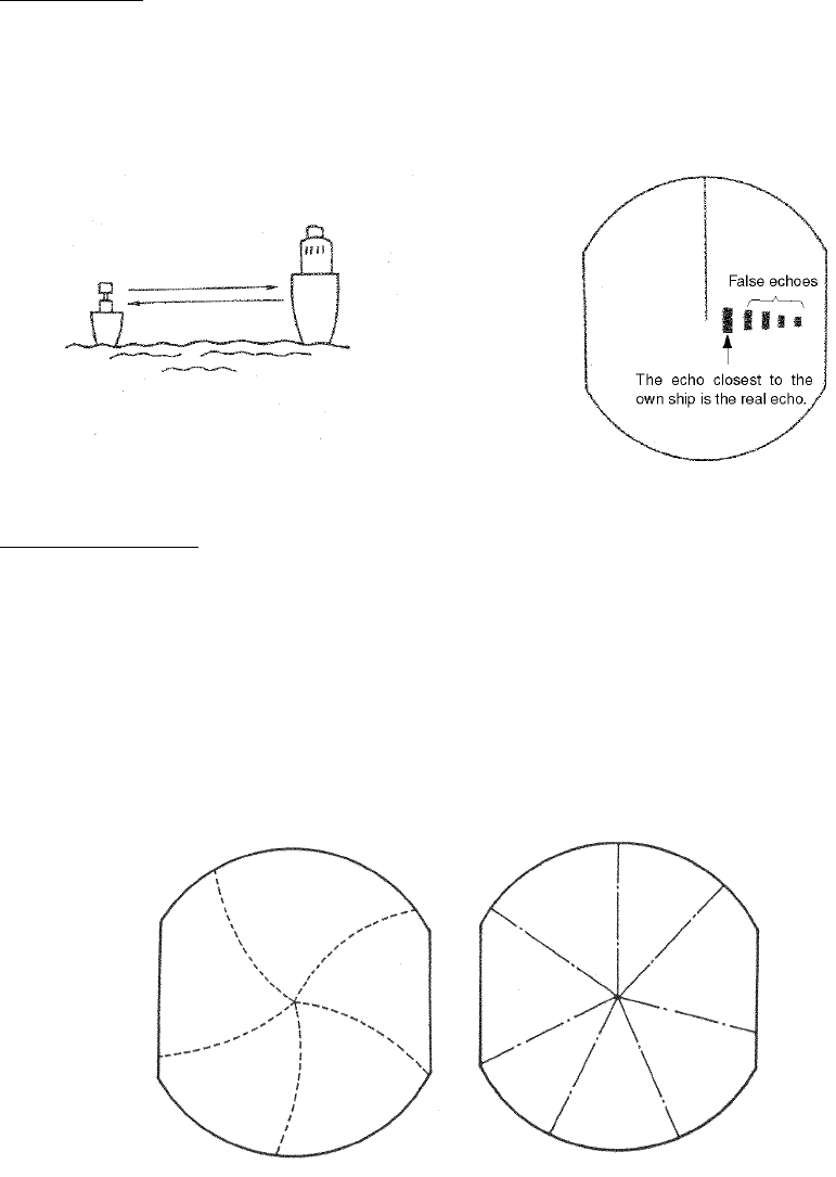
(d) Multiple echo
Multiple echoes are developed by multiple reflections caused by a building or large vessels
that has large vertical surfaces. These echoes are spaced at an equal interval, with the one
that is closest to the own ship being the true echo.
(e) Radar interference
If there is a radar that uses the same frequency as that of the own ship near the own ship,
interferences caused by that radar appear on the PPI screen. These interferences appear as
clusters of spots of varying patterns. Since they do not occur at the same location with time,
they can easily be distinguished from true echoes.
Radar interferences can be reduced or eliminated by choosing "ON" from
"FUNCTION"-"IR".
【Examples of radar interferences】
211
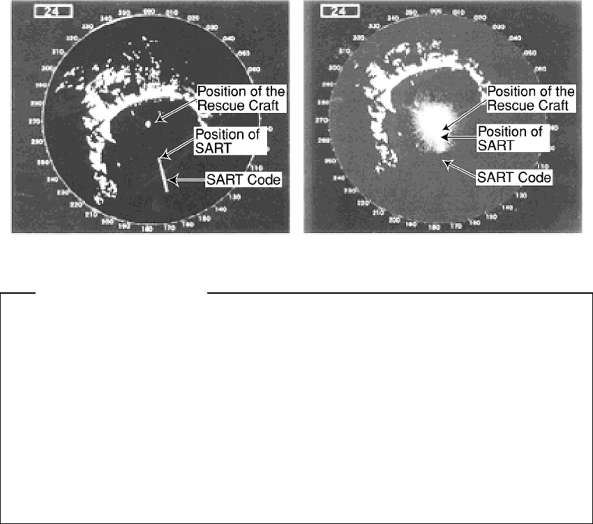
4.4 Display of Radar Transponder
SART (Search and Rescue Radar Transponder) is life preserving device approved by
GMDSS which is used for locating survivors in the event of a disaster or distress. SART
operates in the 9GHz frequency band. When it receives a radar signal (interrogating
radio wave) of 9GHz transmitted by a rescue ship or aircraft radar, SART transmits a
series of respouse signals to the searchers to indicate the distress position.
In order to see the SART or radar beacon mark on the radar screen.
① RANGE SCALE : Select 6 or 12 nm
② SEA CLUTTER control : Set to minimum
③
AUTO SEA
: OFF
④ TUNE control : DETUNED to reduce the clutter
⑤ IR : Set IR OFF
⑥ PROCESS : Set PROCESS OFF
【Example】
When above settings ①to ⑥ are made to display SART signals, objects around
the own ship will not appear on the radar screen, so perform thorough visual
monitoring of the sea area around the own ship to avoid any collision or stranding.
Further, when more than one radar systems are mounted, while using a 9GHz
band radar for searching SART signals, be sure to use another radar as an
ordinary radar to perform monitoring of objects around the own ship to avoid any
collision, check of the position of the own ship to avoid any stranding, and so on.
Need to return the set for normal operation on completion.
Attention
212
5 Maintenance and Inspection
5.1 General Maintenance
WARNING
The customer should refrain from inspecting or repairing the internal parts of this
equipment.
Inspection or repair other than by specialized service personnel may result in
fire or severe electric shock.
Please contact the sales department of Japan Radio Co., Ltd. or your local
branch, outlet or sales office with respect to maintenance and repair.
When performing maintenance in increment weather, please be sure to shut
the main power off. Maintenance work performed without shutting the main
power off may result in severe electric shock.
CAUTION
When cleaning the surface, please refrain from using organic solvents such as
thinner or benzene.
Use of such organic solvents may damage the surface coating.
When cleaning the surface, remove dust and grime and wipe with a clean dry
cloth.
The following maintenance steps are required to ensure that the radar always operates in
the optimal condition. Since breakdowns will be reduced through maintenance, periodic
maintenance is recommended.
General maintenance steps common to all equipment are as follows.
Cleaning
Remove dust, grime and sea water that has adhered to the unit. Use dry cloth to clean
the unit. In particular, use a brush to clean the ventilating opening to ensure smooth flow
of air.
213
5.2 Scanner Unit
WARNING
When performing maintenance or inspection of the scanner unit, be sure to shut
off the main power source. Sudden movement of the scanner may cause
collision and injury to the human body.
Be sure to shut off the main power source when approaching the scanner unit for
the purposes of maintenance or inspection. Exposure to electric waves at
proximate distances may negatively affect the human body.
(1) Radiation unit
If the front of the radiation unit is soiled with soot, salt, paint specks, bird excrement or
other alien matter, electric waves may become attenuated and reflection may occur thus
causing degradation in the performance of the radar.
The radiation unit should be inspected and always kept clean by wiping with cloth
soaked in alcohol or water in the event of soiling.
Solvents such as gasoline, benzene, trichlene or ketone should never be used for this
purpose.
(2) Pedestal
The pedestal and attachment bolts of the scanner unit should be inspected periodically
for erosion and maintained to ensure safety. Painting is the best measure for preventing
erosion and it is recommended that this be undertaken once in half a year.
5.3 Display Unit
Cleaning the cathode-ray tube
When dust adheres to the cathode-ray tube, transparency degrades and the images
become dark.
Cleaning is performed using cloth soaked in water (flannel or cotton). Wiping
vigorously with dry cloth or the use of gasoline or thinner should be avoided.
CAUTION
Vigorous wiping with dry cloth or the use of gasoline or thinner should be
avoided in cleaning the cathode-ray tube.
Such action may cause scratches and deterioration.

214
5.4 Special Parts
JMA-2343
Model
Number
Name Type
Manufacturer
Location of use JRC Code
V201 Magnetron MSF1421B New JRC Scanner unit 5VMAA00049
A101 Circulator H-6AJRD00001 Toshiba Scanner unit 6AJRD00001
A102 Diode limiter NJS6930 New JRC Scanner unit 5EZAA00024
E301 Front end NJT1028 New JRC Scanner unit 5EZAA00039
JMA-2344
Model
Number
Name Type
Manufacturer
Location of use JRC Code
V201 Magnetron MSF1422B New JRC Scanner unit 5VMAA00051
A101 Circulator H-6AJRD00001 Toshiba Scanner unit 6AJRD00001
A102 Diode limiter NJS6930 New JRC Scanner unit 5EZAA00024
E301 Front end NJT1969 New JRC Scanner unit 5EZAA00037
5.5 Circuit Blocks for Repair
NKE-249
Name Unit/ type of circuit Remarks
Modulator circuit CME-307
Receiver NRG-140
NKE-250
Name Unit/ type of circuit Remarks
Modulator circuit CME-308
Receiver NRG-141
Motor unit CBP-153 With rotating pulse generation circuit
Motor brush BRXP05247 Containing 2

215
NCD-4170
Name Type Remarks
Main control circuit CMC-1156
Power supply circuit CBD-1596
Main panel circuit CCK-873
Soft key panel circuit CCK—872
Interior of the monitor unit CKJ-159 CRT + deflecting coil
CRT monitor control unit CCN-366 With socket circuit

216
5.6 Actions to Deal with Abnormalities and Breakdown
In the case of semiconductor circuits, except in cases of problems in the design or inspection of
such circuits or causes that are external or caused by humans, breakdown or deterioration of the
circuit does not often occur. In general, the causes of breakdown that are relatively frequently
found are wire cut in the high resistance device due to high humidity, defect in the variable
resistance and defective contact of switches and relays.
Moreover, in many cases the cause for breakdown is not a defect in parts but rather poor
adjustment (particularly inadequate tuning adjustment) or poor maintenance (particularly defect in
cable contact) and inspecting or readjusting these aspects is often effective in the case of
perceived abnormality or breakdown. The following table should be taken into consideration in
the case of abnormalities or breakdown.
There is always a cause for blown fuse and after replacing the fuse, it is necessary to
investigate the related circuits even when no abnormality remains. However, consideration
should be given to the fact that there is significant variance in the characteristics of fuse. Please
refer to the list on the fuses used given in Section 9.4.
No. Condition of the Breakdown Conceivable Cause
1 Nothing appears on the
CRT.
a. Breakdown in the power supply unit (CBD-1596)
b. Fuse F1 has blown
c. Breakdown of the monitor
d. Breakdown of the main control circuit (CMC-1156)
e. The electric power of the ship is inadequate.
2 The scanner unit does not
rotate.
a. Fuse F2 has blown
b. Breakdown in the motor unit (JMA-2343: CML-645
H-7BDRD0023 inside the scanner unit, JMA-2344:
CBP-153)
c. Breakdown of the safety switch of the scanner unit
(JMA-2344 only)
3 The scanner unit rotates but
no radar image appears
(characters and markers
are, however, displayed).
a. Breakdown of the receiver (JMA-2343: CAE-457,
JMA2344: CAE-457-1)
b. Breakdown of the main control circuit (CMC-1156).
What is the condition of the transmission trigger (TI)?
c. Breakdown of the motor unit (JMA-2343: CML-645
H-7BDRD0023 inside the scanner unit, JMA-2344:
CBP-153)
4 The operation switches do
not work.
a. If the switches do not work even after turning the power on
again, breakdown in the main control circuit (CMC-1156).
b. Breakdown in the main operation panel circuit
(CCK-873) or soft key panel circuit (CCK-872)
c. Cut in the cable connecting the operation unit.

217
No. Condition of the Breakdown Conceivable Cause
5 Only noise is displayed and
no radar image is displayed
(characters and markers
are, however, displayed).
a. Modulator (JMA-2343: CME-307, JMA2344: CME-308)
b. Defective magnetron
c. Breakdown in the main control circuit (CMC-1156)
d. Defective tuning voltage
6 While radar images are
displayed, the characters
and markers are not
displayed.
a. Breakdown in the main control circuit (CMC-1156).
7 Reception is poor. a. Deterioration or fault in the magnetron
b. Breakdown in the modulator (JMA-2343: CME-307,
JMA-2344: CME-308). Defect in the pulse width
switching?
c. Breakdown in the receiver (JMA-2343: CAE-457,
JMA-2344: CAE-457-1)
d. Water damage to the radiation unit or cables between
equipment (soiling of the radiation unit, adherence of
ice or snow, internal erosion of the cable between
equipment)
e. Defective tuning voltage
f. Interruption in the pulse switching signal (PW)
8 The image is warped or
drifts.
a. Breakdown or defective adjustment of the monitor
b. Interruption in the synchronizing signal for horizontal
signal (HS) and vertical signal (VS)
c. Breakdown in the CRT monitor circuit (CNN-366)
9 Nothing happens on the
screen when the fixed
distance marker, variable
distance marker, electronic
cursor or panel lighting
switches are pushed.
a. The brightness adjustment is at the minimum level.
b. Breakdown in the main control circuit (CMC-1156)
10 The screen returns to the
initial state during operation.
a. The electric power of the ship is inadequate.
b. Breakdown in the main control circuit (CMC-1156)
c. Breakdown in the power supply unit
11 The alarm does not activate. a. Breakdown in the main control circuit (CMC-1156)
12 The radar wake does not
operate.
a. Breakdown in the main control circuit
b. The image brightness is too low.
13 The display does not
change to true bearing
(north-up) or course up.
a. There is no data being received from the bearing
sensor (NMEA).

218
6 After-sales Service
★
★★
★ When asking for repair
When a system failure is suspended, read Chapter 4, 5 and 9 carefully and re-check the
abnormal part.
If it is still considered to be a failure, stop the operation at once and consult with the
dealer you purchased the product, our sales department or your nearest branch or
business office.
●
●●
● Repair within the warranty period
If the failure occurred under proper operation in accordance with the instruction
manual, the dealer or JRC shall repair the product without charging. In case of any
other failure occurred due to mis-operation or natural disaster, the repair work will be
charged.
●
●●
● Repair after the warranty period has expired
If the product is recoverable by repairing, we will repair it upon your request.
●
●●
● Items to be identified
☆ Product name, model name, manufacturing date and serial number
☆ Failure condition (as detailed as possible: see the Radar Failure Checklist on Page
219.)
☆ Your company/organization name, location and telephone number
★
★★
★ Recommendation of maintenance inspection
Although it depends on your operating condition, the performance of the product may
be lowered due to parts wear.
We recommend maintenance inspection, apart from the normal maintenance work.
For maintenance inspection, consult with the dealer you purchased the product, our
sales department, or your nearest branch or business office.
Note that this maintenance inspection will be charged.
For detail of after-sale service, contact the dealer you purchased the product, our sales
department, or your nearest branch or business office.
☞Contact : See the list at the end of the manual.

219
RADAR FAILURE CHECKLIST
When ordering for repair, check the following items, fill in the sheet and send it to us.
If there is any uncertain items, contact your ship and give us correct information on the
product.
Ship name: Phone: Fax:
Radar general model name:JMA― Serial No.:
(Write the full model name correctly)
(1) Check the following items in the order of the number, and circle the applicable answer
between YES or NO.
If the item cannot be determined as YES or NO, explain in detail in the item (15), Others.
(2) If any of the items (1) through (4) is marked as NO, check the fuse of the product (refer
to Section 5.6 and 9.4).
(3) Check the items (4) through (14) while the transmission (TX) is ON.
* Functions mentioned in the items (13) through (14) may be optional. If the function is optional, answer is not necessary.
No. Check Item Result
(1) Power can be turned on. (The lamp on the operation panel is lit.) YES NO
(2)
A few minutes after powering-on, it will become stand-by status (TX Ready). YES NO
(3)
When powering-on (or TX ON), the CRT displays something (CRT is lit). YES NO
(4) The scanner unit rotates at the transmission (X-MIT) ON. (Check the
following items while transmission is ON.) YES NO
(5) Tuning is enabled. (Check with the range of 6NM or more.) YES NO
(6) Fixed marker is displayed. YES NO
(7) VRM is displayed. YES NO
(8) White noise is displayed while set at SEA, RAIN minimum, GAIN
maximum, IR-OFF and maximum range. YES NO
(9) Target reflection echo is displayed. YES NO
(10) Sensitivity of reflection echo is normal. YES NO
(11) EBL is displayed. YES NO
(12) Cursor mark moves. YES NO
*(13) GYRO course can be set and normally displayed. YES NO
*(14) LOG speed can be normally displayed. YES NO
(15) Others (Error message, etc)

220
7 Disposal
7.1 Equipment Disposal
Dispose of this equipment by following the ordinances or regulations of the local authorities
in charge of the disposal site.
7.2 Disposal of Used Batteries
WARNING
Before disposing of used lithium batteries, insulate by affixing tape to the
positive and negative terminals or by other means. Otherwise, short-circuiting
may occur, resulting in heat generation, bursting or ignition.
On this equipment, lithium batteries are used for:
BT1 in the CPU control circuit (CMC-1156) (Sanyo electric CR2032-FT6-1).
● Do not keep used lithium batteries but dispose of them immediately after as
non-combustible waste.
● Before disposing of used lithium batteries, insulate by affixing tape to the positive and
negative terminals or by other means. In the area where used batteries are separated
from other waste, dispose of them by following the local regulations.
7.3 Disposal of Used Magnetron
The scanner unit in this radar use a magnetron.
● After replacing it, return the used one to your local distributor or our sales office.
For detail, ask your local distributor or our sales office.

221
8 Specifications
8.1 General
(1) Scanning mode Raster scanning, PPI
(2) Display unit 10-inch square monochrome CRT
(3) Display color Green
(4) Ranges
JMA-2343
0.125, 0.25, 0.5, 0.75, 1.5, 3, 6, 12, 24, 36, 48 NM
JMA-2344
0.125, 0.25, 0.5, 0.75, 1.5, 3, 6, 12, 24, 36, 48, 64 NM
(5) Range resolution 25m maximum
(6) Minimum range 25m maximum
(7) Bearing accuracy ±1°maximum
(8) Bearing discrimination
JMA-2343 4.2˚
JMA-2344 2.2˚
(9) Bearing measurement mode True/Relative bearing
(10) Environmental condition
・ Temperature Scanner unit -15˚C to +55˚C
Display unit -15˚C to +50˚C
・ Relative humidity 93% maximum at 40˚C
・ Relative wind velocity
Scanner unit 36.0m/sec (70 knots)
(11) Power consumption
・ DC input (12,24,32V)
JMA-2343 Approx. 60W
JMA-2344 Approx. 65W
・ AC input (Note) Approx. 100VA
(100/110/115/200/220/230V, 50/60Hz single phase)
(12) Input power range DC10.8V to DC42V
(13) Preheating time Approx. 90 seconds
(14) Warm-up time Approx. 3 seconds maximum
(Note) The following rectifiers need be used when AC input is to be used : NBA-797A

222
8.2 Scanner Unit (NKE-249/250)
(1) Dimensions
NKE-249
・ Diameter 620mm
・ Height 275mm
NKE-250
・ Swing circle 1220mm
・ Height 432mm
(2) Mass
NKE-249 Approx. 10.5kg
NKE-250 Approx. 24kg
(3) Polarization Horizontal
(4) Directivity characteristics
NKE-249
・ Horizontal beam width 4˚
・ Vertical beam width 25˚
・
Side lobe level
-21dB maximum (less than ±10
˚
from main lobe)
NKE-250
・ Horizontal beam width 2˚
・ Vertical beam width 30˚
・
Side lobe level
-23dB maximum (less than ±10
˚
from main lobe)
-26dB maximum (other than ±10
˚
from main lobe)
(5) Rotation
NKE-249/250 Approx. 27 rpm
(6) Transmitter frequency 9410±30MHz
(7) Peak power
NKE-249 4kw
NKE-250 6kw
(8) Transmitter tube
NKE-249 Magnetron : MSF1421B
NKE-250 Magnetron : MSF1422B
(9) Pulse length/PRF
NKE-249 0.08μs /2250Hz (0.125, 0.25, 0.5, 0.75, 1.5NM)
0.25μs/1700Hz (1.5, 3 NM)
0.5μs/1200Hz (3, 6 NM)
1.0μs/650Hz (6, 12, 24, 36, 48 NM)

223
NKE-250 0.08μs/2250Hz (0.125, 0.25, 0.5, 0.75, 1.5 NM)
0.25μs/1700Hz (1.5, 3 NM)
0.5μs/1200Hz (3, 6 NM)
1.0μs/650Hz (6, 12, 24, 36, 48, 64 NM)
(10) Modulator Solid state modulator driver
(11) Duplexer Circulator and diode limiter
(12) Mixer MIC front-end
(13) IF amplifier
・ Intermediate frequency 60MHz
・ Band width 20/6/3MHz
・ Characteristic Semi-log characteristic
(14) Noise figure 6dB maximum

224
8.3 Display Unit (NCD-4170)
(1) Dimensions
・ Width 278mm
・ Height 242mm
・ Depth 275mm
(2) Mounting Table-top mounting
(3) Mass Approx. 9kg
(4) Cathode-ray tube 10-inch square monochrome CRT
(5) Range scales
Range (NM) Range ring interval (NM) Number of rings (NM)
0.125 0.0625 2
0.25 0.125 2
0.5 0.25 2
0.75 0.5 3
1.5 0.25 6
3 0.5 6
6 1 6
12 2 6
24 4 6
36 6 6
48 8 6
Only JMA-2344 64 16 4
(6)
Range ring accuracy
±0.9% of selected range or ±8m, which is greater.
(7) VRM VRM1/VRM2
JMA-2343 0 to 48 NM, digital numeric display of 3 figures
JMA-2344 0 to 64 NM, digital numeric display of 3 figures
(8) EBL EBL1/EBL2
0˚ to 359˚, digital numeric display of 3 figures
(9) Tuning mode Manual or automatic
(10) Bearing scale 360˚ scale graduated at intervals of 1°
(11) Ship’s heading marker Electronic
(12) Sea surface clutter suppression Manual or automatic
(13)
Rain and snow clutter suppression
Manual or automatic
(14) Radar wakes display 15 sec/30 sec/1 min/3 min/6 min/15 min/30 min/
continuous
(15) Center move 66% maximum of PPI’s radius

225
(16) Keys/Controls
・Main panel STBY/OFF key
X-MIT/OFF key
[TUNE] control
[GAIN] control
[SEA] control
[RAIN] control
RANGE key
VRM key
EBL key
BRIL/HL OFF key
MENU key
ENTER key
Cross key
・Software key panel Software key : 4
(17) Software key function ・DISPLAY Screen expansion [EXP]
Center move [CENTER]
Fixed range rings [RR]
Cursor [CUR]
・PROCESS Clutter suppression
[AUTOOFF/A-SEA/A-RAIN]
Interference rejection [IR]
Tune mode [TUNE]
Radar wakes [WKS]
・GUARD Zone make [MAKE]
Alarm setting [ALM]
Sensitivity [SENS]
Alarm mode [ALM]
OFF
OFFOFF
OFF
STBY
STBYSTBY
STBY
OFF
OFFOFF
OFF
X
XX
X-
--
-MIT
MITMIT
MIT
▲
▲▲
▲
RANGE
RANGE RANGE
RANGE
▼
▼▼
▼
VRM
VRMVRM
VRM
EBL
EBLEBL
EBL
MENU
MENUMENU
MENU
ENTER
ENTERENTER
ENTER
HL OFF
HL OFFHL OFF
HL OFF
BRIL
BRILBRIL
BRIL

226
(18) Menu
・FUNCTION EBL1/VRM1 mode setting [EBL1/VRM1]
(Fix [FIX]/Float [FLOAT]/Parallel line [PLINE])
EBL2 setting [EBL2]
VRM2 setting [VRM2]
EBL read out [EBL READOUT]
Zooming of echo image on PPI [ZOOM]
True motion/Relative motion [TM*/RM]
Heading mode [HDG MODE]
(Head-up [H-UP]/North-up [N-UP]*/
Course-up [C-UP]*)
Image process [PROCESS]
・DISPLAY Position display [POSITION]
(Own ship [L/L or TD]/Cursor [CUR L/L]/
Waypoint [WPT L/L])*
Waypoint display [WAYPOINT]
Range unit [RANGE]
(NM/KY/KM)
Timed transmission [TIMED TX]
(Transmission period [TX PERIOD]/
Stand-by period [STBY PERIOD])
・RADAR SET-UP 1 Buzzer volume [BUZZER]
Panel dimness [DIMMER]
Transmitter pulse width [TX PLSE]
(1.5NM/3NM/6NM)
Bearing reference [BEARING]
(Magnetic bearing [MAG]/True bearing [TRUE])*
Multi display unit setting [MULTI DISPLAY]
・RADAR SET-UP 2 Language
(English/Japanese/Chinese/Francais/ Espanol/
Italiano/Norsk/Deutsch/Korea)

227
(19) Input from external device GPS (NMEA0183)
Electric compass or GPS compass (NMEA0183)
NMEA0183 version : v1.5, v2.1, v2.3
Latitude/Longitude : GGA, RMA, RMC, GLL
Waypoint : RMB, BWC
Speed : VTG, RMA, RMC, VHW
Course : VTG, RMA, RMC
Ship’s head : HDT, VHW, HDM, HDG
VARIATION : HDG, RMA, RMC
TD (LoranC time difference) : GLC
,
GTD
,
RMA
(20) Output to external device Cursor data (Bearing/Range)
NMEA0183 RSD sentence**
Sub monitor
(Vertical/Horizontal synchronous signal,
video signal)
* You need a connection with navigation device or bearing sensor.
** Data output only when pushing ENTER key.

228
8.4 Rectifier Unit (NBA-797A)
(1) Dimensions
・Width 270mm
・Height 430mm
・Depth 175mm
(2) Mounting Wall type, drip proof structure
(3) Mass Approx. 18kg
(4) Input power AC 100/110/115/200/220/230V±15%
50/60Hz, Single phase
(5) Power consumption 200VA
(6) Output DC 26V, 7A
8.5 Unit-to-unit Spacing
Maximum Cable Length Standard Cable Length
Scanner to display 20m 15m
Display to rectifier (Note) 2m
(Note) About power cable length between display to rectifier, see "9.5.3 Selecting
a Long Cable"
Install each equipment so that the length of the cable between a snanner unit and a
display unit does not exceed 20m. If the regular length is exceeded, it may become
the cause of causing poor adjustment and the defect of a system of operation.
・The standard cables are provided with connectors and plugs.
Attention
229
9 Installation
This chapter has been written for the service technicians to read in case of installation.
WARNING
Only specialized personnel shall perform installation work.
Installation work performed by personnel other than specialized personnel
may cause breakdown of the equipment, poor performance, fire, severe elec-
tric shock and other property and human damages.
9.1 General
Proper installation of a radar unit is essential for extracting full capability of the unit
reliably and for facilitating troubleshooting and maintenance. Follow the guidelines
given below when installing the radar unit.
(a) Install the scanner unit as high as possible while taking its weight into consideration.
(b) Install the display unit in the wheel house for comfortable observation.
(c) The scanner unit and display unit are connected by 10 to 20 m compound cable with 20
conductors with an internal shield. The maximum permissible cable length is 20 m.
Cables larger than 20 m would deteriorate the radar performance of the radar unit.
230
9.2 Installing the Scanner Unit
9.2.1 Selecting the installation location
CAUTION
The scanner unit shall be installed where there are not large obstacles in the
direction of the ship's heading line in the same plane.
If there is a large impediment in the same plane as the scanner unit, this may
cause the generation of folse echoes. In particular, if such folse echoes
appear at the ship's heading line, monitoring will be difficult and this may
cause inadequate forecasting of danger.
Do not install the scanner unit near chimney's or the exhaust of chimneys.
Soot will cause the performance of the radar to decrease and heat may cause
breakdown.
Do not install direction antenna or VHF antenna in the vicinity of the scanner
unit. Doing so may cause noise in the antenna reception.
Consideration should be given to separating the radar cable from the cables
for the direction antenna and VHF antenna.
These cables should never be bundled into one. Doing so may cause noise
in the antenna reception.
9.2.2 Installation procedure
(a) If it is found that there is no height above the roof of the wheel house enough to directly
accommodate a scanner unit, install a pedestal or radar mast.
(b) In addition to a pedestal or radar mast, it is necessary to provide an appropriate staging
for convenience in installation, maintenance, adjustment, and repair of the scanner
unit.
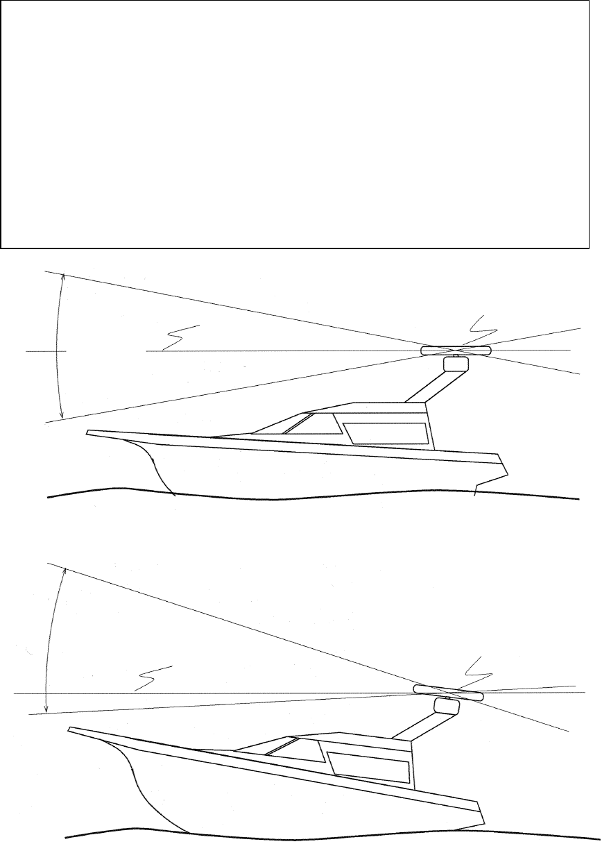
231
(1) Precautions to be observed when installing the scanner unit on a power boat
The bow of a power boat is kept in a raised position when it is running at a high
speed. Consequently, if the radar's scanner unit is installed horizontally when the
boat is stopped, the following conditions will occur if the trim (elevation angle of the
ship's bow at run time) exceeds 1/2 of the vertical beam width (θ):
• On the front side, the water surface lies outside the beam, weakening the radio
wave that is incident to the target on the water surface. Consequently, the
echo generated by this target is will hardly be visible on the radar screen.
Conversely, on the rear side:
• Since the radio wave that is incident to the water surface is stronger, strong sea
clutter will develop. For vessels on which the trim is 1/2 or greater than the ver-
tical beam width (θ), it is recommended that the scanner unit be installed in
such an orientation that it is tilted forwards.
[When the ship is stopped or running at a slow speed]
[High speed run: the lower part of the beam is almost horizontal.]
Beam width θ
Radar scanner unit
Horizontal line
Beam width θ
Radar scanner unit
Horizontal line
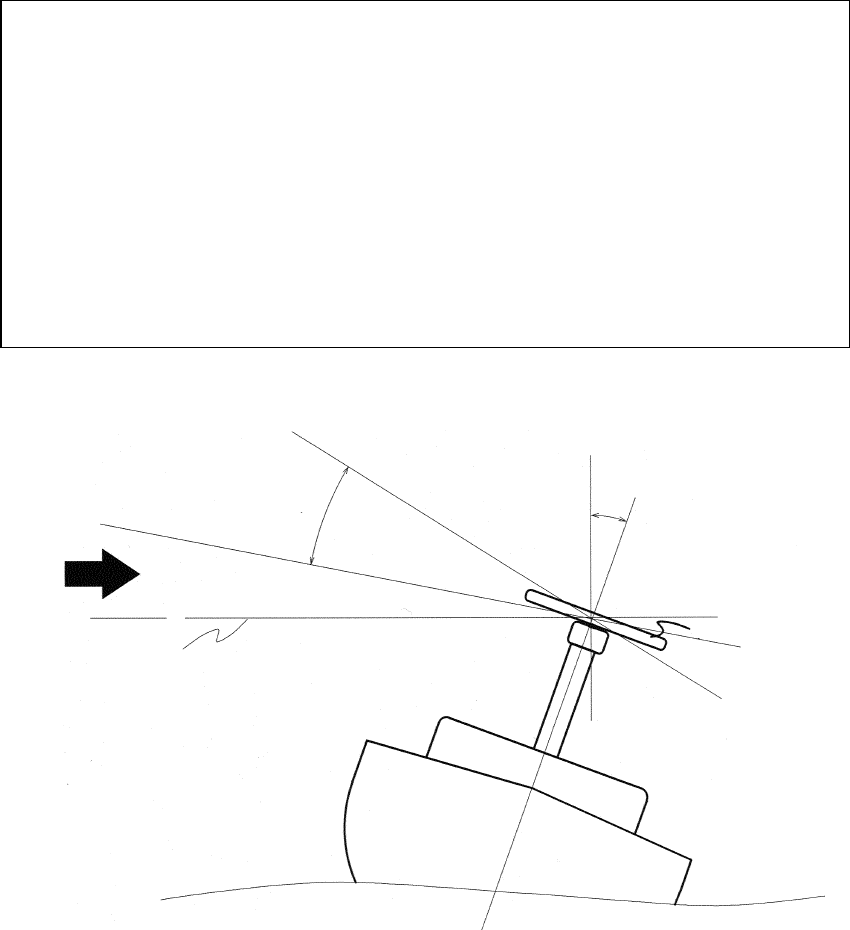
232
(2) Precautions to be observed when installing the scanner unit on a yacht
A yacht heels on the lee side when a wind with a certain level of force blows.
The following condition occurs if the heel angle exceeds 1/2 of the beam width:
• On the windward side, the water surface lies outside the beam, weakening the
radio wave that is incident to the target on the water surface. Consequently,
the echo generated by this target is will hardly be visible on the radar screen.
Conversely, on the lee side:
• Since the radio wave that is incident to the water surface is stronger, strong sea
clutter will develop. For yachts on which the heel is 1/2 or greater than the ver-
tical beam width (θ) , it is recommended that the scanner unit be installed on a
mounting base so that the scanner unit can be tilted on the left and right sides
according to the heel angle.
Beam width θ
Heel angle Φ
Radar scanner unit
Horizontal line
Wind
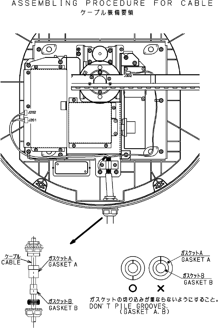
233
9.2.3 Connection of cables to be assembled
(1) Radome scanner unit (NKE-249)
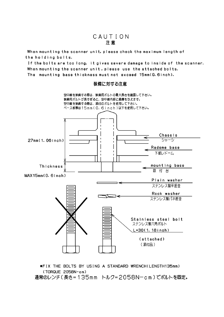
234
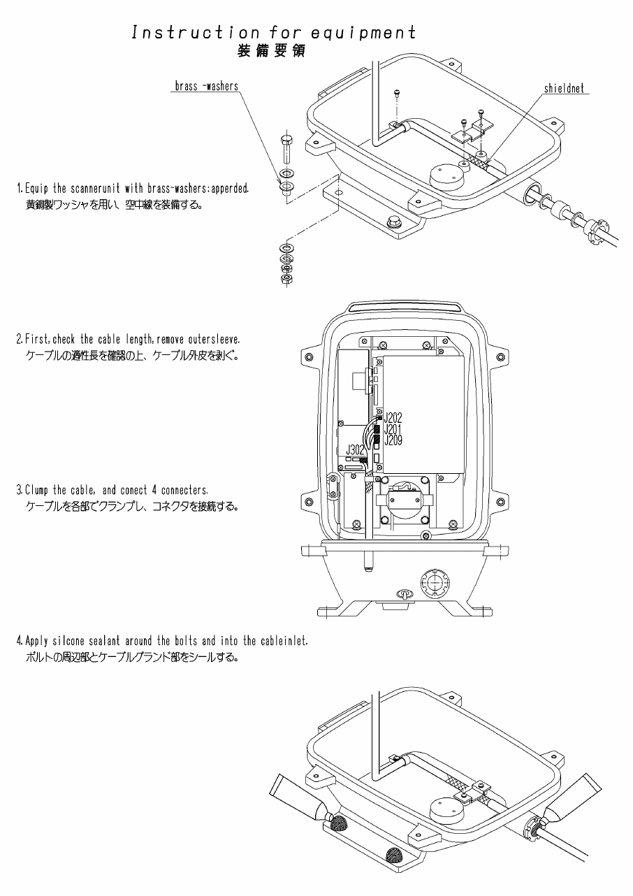
235
(2) Rotary scanner unit (NKE-250)

236
9.3 Installing the Display Unit
9.3.1 Selecting the installation location
The display unit should be installed at least 1 meter from the magnet compass.
If the display unit is installed in the vicinity of the magnet compass, the compass
may be affected.
Consider the following points when determining the location of the display unit:
(a) Install the display unit in a location that provides the operator with a convenient
viewing position.
(b) Take after-installation maintenance into consideration.
9.3.2 Installation procedure
(a) Install the display unit by drilling holes using the exterior dimension drawings of the
display unit as reference. Monitoring will be facilitated if the display is positioned so
that the operator faces the ship's heading line (the CRT faces astern).
(b) Wherever possible, select a location that is free of vibration.
9.3.3 Connecting the power cable
(a) Connect the power cable plug to the J1(POWER) connector on the rear panel of the
display unit.
(b) Connect the plug of the cable from the scanner unit to the J2(SC UNIT) connector on the
rear panel of the display unit.
● Use an adequately heavy earth cable when connecting the earth terminal of the
display unit to the ship body.
Attention
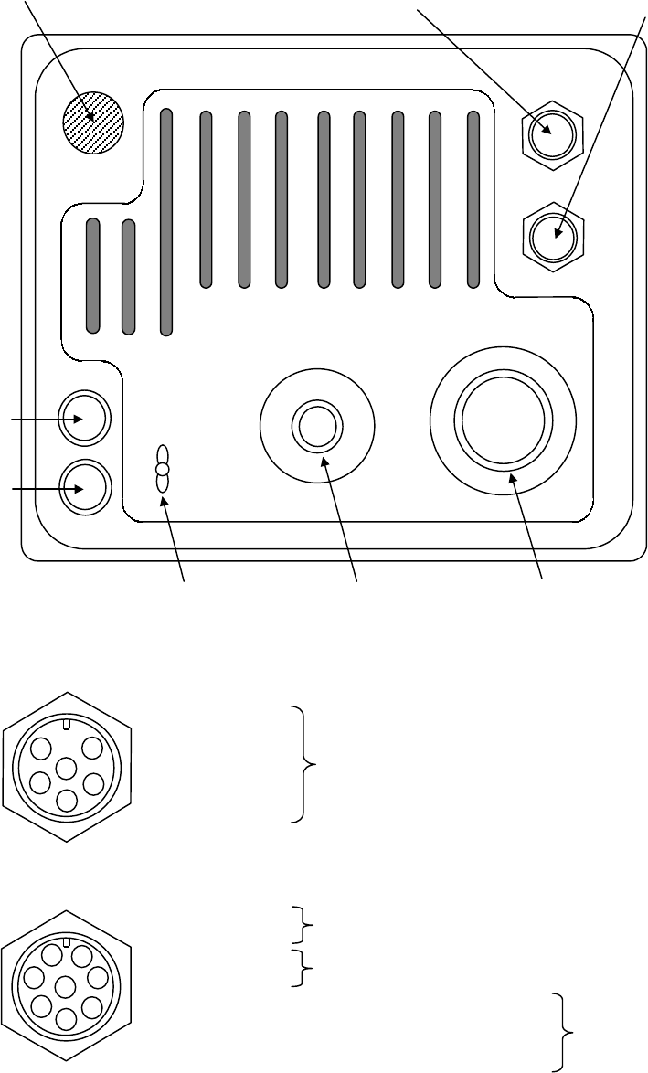
237
9.3.4 Display unit rear panel
1
2
3
4
5
6
GPS connector (J3)
2
3 4 5
6
8
1 7
External connector (J4)
F1
F1F1
F1
F2
F2F2
F2
E
EE
E
EXT2
EXT2EXT2
EXT2
EXT1
EXT1EXT1
EXT1
GPS
GPSGPS
GPS
POWER
POWERPOWER
POWER
SC
SCSC
SC
UNIT
UNITUNIT
UNIT
Ground terminal Power connector (J1) Cable assembly connector (J2)
Fuse (F2)
Fuse (F1)
GPS connector (J3) External
connector (J4)
Rubber stopper
(for connecting the optional ex-
ternal connector (J5))
① +12V
② GND
③ NAVCOM
④ NAVRX
⑤ NAVTX
① DATA+
② DATA-
③ CMPS+
④ CMPS-
⑤ SVD (Image signal)
⑥ SHS (Horizontal synchronization signal)
⑦ SVS (Vertical synchronization signal)
⑧ GND
To GPS or LORAN
To cursor data input device
To electromagnetic compass/ GPS compass
To sub-monitor
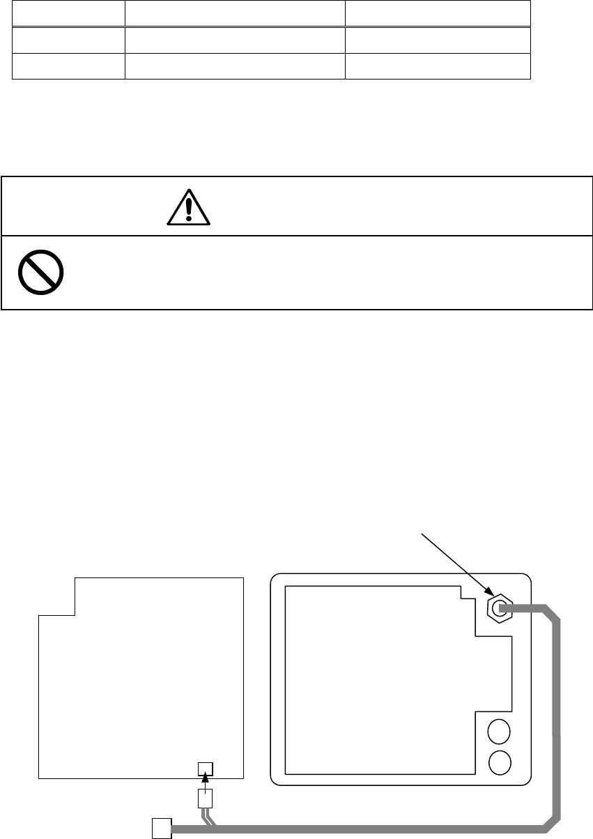
238
※ The following should be used as the plug side connector for connecting to J3 and J4
Connector Type JRC Code
For J3 LTWD-06BFFA-L180 5JCAS00031
For J4 LTWD-08BFFA-L180 5JCAS00027
9.3.5 Connection of the external buzzer
CAUTION
Only qualified service personnel should perform external buzzer cabling work.
Erroneous connection may cause breakdown or defective operation.
The 5 pin connector side of the cable equipped with connector (7ZCRD0749) should be
attached to EXT2 on the rear panel of display unit after removing the rubber stopper. The
2 pin connector side should be connected to J5 of the display unit main control circuit
(CMC-1156). The 3 pin connector need not be.
Use the 5 pin connector (Type: LTWD-05BFFA-L180, JRC code: 5JCAS00030) for the plug
side connector connected to EXT2.
J5 (2 pin)
Main control circuit
(CMC-1156)
Power supply circuit
(CBD-1596)
F1
F2
External connector J5 (5 pin)
A
ttach after removing the rubbe
r
stopper.
2 pin connector
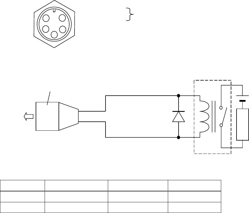
239
EXT2 Connector (J5)
Example of connection of an external buzzer
Example of Parts
Name Manufacturer Type JRC Code
Relay Takamizawa LZ12H 5KLAC00033
Diode Hitachi V06C 5TXAE00016
1
2
3
4
5
① EXTBUZ
② +12V
③
④
⑤
To external buzzer control
Buzzer
EXTBUZ
+12V
12V relay
Protective diode
to EXT2
LTWD-05BFFA-L180
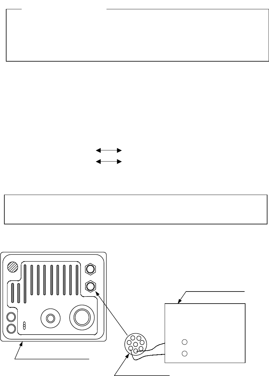
240
9.3.6 Connecting an electromagnetic compass
Ensure that the output of the inboard power supply and rectifier unit and connection to
the power cable is correct.
Erroneous connection or voltage may cause breakdown.
It is possible to input information on bearing to the radar display unit if you use the elec-
tromagnetic compass with a NMEA0183 output terminal.
(It is impossible to connect if you use the electromagnetic compass without a NMEA0183
output terminal.)
(1) Solder the data cable of electromagnetic compass (with NMEA0183 output) to the 8 pin
connector. The polarity is as shown below and care should be taken in making this
connection.
8 pin connector (pin 3) Electromagnetic compass data (+)
8 pin connector (pin 4) Electromagnetic compass data (-)
Type of LTWD-08BFFA-L180 (JRC code: 5JCS00027) should be used as the 8 pin
connector.
Unless the connection between the 8 pin connector and data cable is correct,
correct data will not be obtained.
(2) Connect the 8 pin connector to J4 (EXT1) on the rear panel of the display unit.
This completes the cabling of the electromagnetic compass.
Attention
Electromagnetic compass
F1
F2
E
EXT2
EXT1
GPS
POWER
SC UNIT
8P connector
(
black
)
J4
Radar display unit rear panel
1
2
3 4 5
6
7
8 Data -
Data +
241
9.4 Modifications to be Made to the Inboard Power Supply
Be sure to use the correctly rated fuse. In the event incorrectly rated fuse is used,
this may cause breakdown in the equipment.
Make modifications as shown below based on the inboard power supply.
(Fuse for 24V is incorporated upon shipment of the equipment)
1.
1.1.
1. Display unit
Display unit Display unit
Display unit
Fuse rating
F1 F2
Inboard power supply
Rating JRC Code Rating JRC Code
DC12V 6.3A 5ZFAD00336 10A 5ZFAD00539
DC24/32V 3.15A 5ZFAD00227 5A 5ZFAD00364
2. Scanner unit
2. Scanner unit2. Scanner unit
2. Scanner unit
No modifications need to be made with respect to the scanner unit.
Attention
242
9.5 Cable Assemblies
9.5.1 Inter-unit cable (CFQ6774-10/15/20, CFQ6882-10/15/20)
(a) This cable is used to connect the display unit to the scanner unit.
(b) Use the following cables with connectors for this radar equipment.
Cable length JRC Code for JMA-2343 JRC Code for
JMA-2344
Remarks
15m
10m
20m
CFQ6774-15
CFQ6774-10
CFQ6774-20
CFQ6882-15
CFQ6774-10
CFQ6882-20
Standard
Option
Option
Color Number of Conduc-
tors/Diameter (mm)
Signal Name
Shielded wire (conductor) : Black
7/0.20 TI
Shielded wire (shield) TIE
Co-axial cable (conductor) 7/0.20 VD
Co-axial cable (shield) VDE
Red (Thick) 50/0.18 1A
Yellow (Thick) 50/0.18 1A
Blue (Thick) 50/0.18 2A
Purple (Thick) 50/0.18 2A
Green (Thick) 50/0.18 1A
Pink (Thick) 50/0.18 1A
Gray (Thick) 50/0.18 2A
Brown (Thick) 50/0.18 2A
Orange (Middle thick)
34/0.18 BP
Green 7/0.20 BZ
Yellow 7/0.20 COM+
White
Twisted pair
7/0.20 COM-
※The outside diameter size of the cable :11.5±0.5 [mm]
Only JMA-2344
243
9.5.2 Power cable (CFQ-6776)
The radar unit is provided with a 2 m power cable with connectors
Color Number of Conductors
/Diameter
Cross Section
(mm2) Polarity
White 50/0.18 1.25
+
Black 50/0.18 1.25
-
Ensure that the output of the inboard power supply and rectifier unit and connection to
the power cable is correct.
Erroneous connection or voltage may cause breakdown.
9.5.3 Selecting a long cable
The effective voltage of the input to the radar is the voltage at the inboard power
supply minus the voltage drop caused by the power cable. Too thin or long a
power cable incurs a large voltage drop and may not be able to supply adequate
power to the radar. In is recommended that the following guidelines be observed
when selecting the power cable for your radar:
(a) Consider the possible voltage regulation of the inboard power supply (Vs).
(b) Use the following equation to calculate the voltage drop:
V=2LRKI
L:represents the cable length.
R:represents the direct-current resistance (<Ω>/m) at 20<℃>
K:represents the conductor resistance temperature coefficient (= 1.22)
I :Maximum peak current (A)
(c) The table below lists the direct-current resistance (R) and permissible current
(Imax) of several cables.
Cable Type R (20℃) Imax (45℃, continuous)
CVVS2×1.25 16.7 Ω.km 13A
CVVS2×2.0 9.42 Ω/km 19A
CVVS2×3.5 5.30 Ω/km 26A
The cable to be used must possess a sufficient permissible current (Imax) characteristic.
Attention
244
9.6 After-installation Adjustments
9.6.1 Installation-time check
(a) After completing the installation procedure, it is necessary to check the radar unit to
verify that all installation steps have been conducted as instructed. In particular,
check for correct cabling, for normal component operating state, for water leakage in the
scanner unit, and for proper grounding of braided shielding cable.
9.6.2 Functional checks
(a) After completing the installation-time check and before checking the operation of the
radar, make sure that the output voltages of the inboard power supply fall within their
permissible range.
(b) Read "3 Basic Operation" carefully and thoroughly and make sure that the radar
functions normally. Then, manipulate all controls and menu functions to ensure that
they function normally.
(c) If it becomes necessary to make an adjustment though the radar unit is normal, read
"9.7 Adjustment Procedures" carefully and follow the instructions given in that section.
9.6.3 Adjustment items
(a) Radar's bearing adjustment is mandatory.
(b)
If the control is not positioned near the center of the scale during tuning or if tuning fails,
make a coarse tuning from the "TUNE PRESET" menu.
(c) If there is a difference between the range displayed on the radar's PPI screen and the
actual range, adjust the range from the "DISPLAY TIMING" menu.
(d) The "BUZZER" menu can be used to adjust the volume of the alarming buzzer.
(e) The "STC PRESET" menu can be used to adjust the STC.
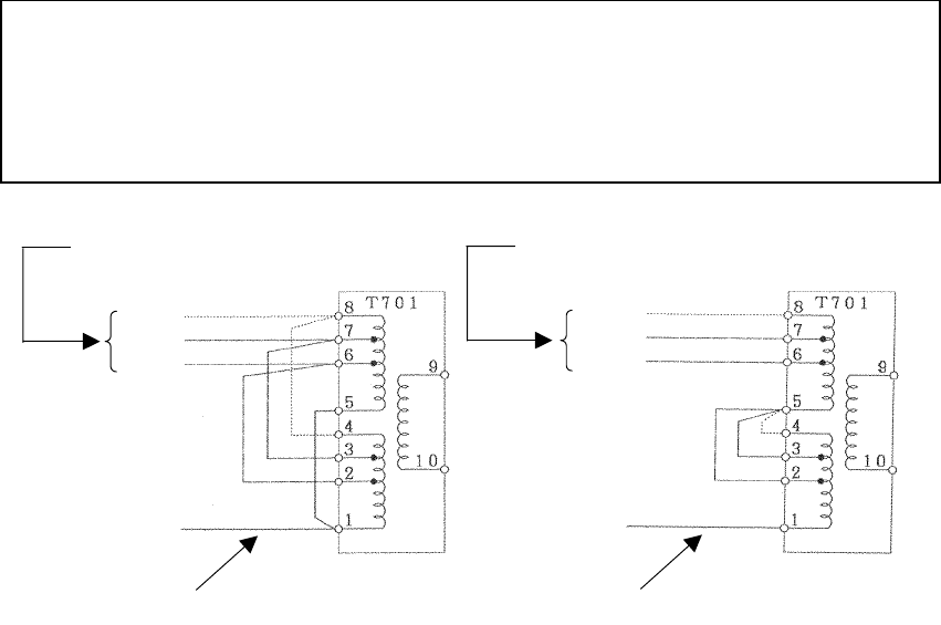
245
9.6.4 Rectifier unit
● The rectifier unit can run on inboard voltages of 100/110/115 VAC and 200/220/230
VAC provided that connections at the input terminals on the NBA-797A T701 are
changed. The figures below show how to change the connections at the input ter-
minals.
100/110/115 VAC 200/220/230 VAC
[Reconnecting the NBA-797A input terminals]
Reconnect according to the input voltage.
115V
110V
100V
This terminal must not be reconnected.
Reconnect according to the input voltage.
230V
220V
200V
This terminal must not be reconnected.
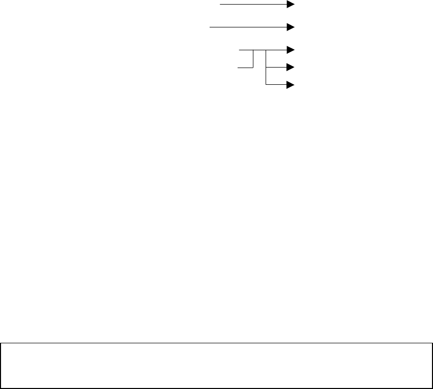
246
9.7 Adjustment Procedures
9.7.1 General adjustments
1. Adjustments to be made when a part is replaced
1. Adjustments to be made when a part is replaced1. Adjustments to be made when a part is replaced
1. Adjustments to be made when a part is replaced
Adjustments need to be performed when major parts of the radar unit. are replaced.
(a) When the V101 magnetron is replaced Tuning
(b) When the E101 front end is replaced Tuning
(c) When the V901 Cathod-ray tube is replaced* Off center adjustment
When the CRT monitor PCB is replaced Brilliance level adjustment
Focus adjustment
*: When exchanging V901 (CRT), the Direction coil implement in the stuck condition.
Incidentally, It is possible to arrange in cathode-ray tube monitor chassis (CKJ-159)
2. CRT monitor off center adjustment
2. CRT monitor off center adjustment2. CRT monitor off center adjustment
2. CRT monitor off center adjustment
(a) This adjustment must be performed on the centering magnet (permanent magnet)
located immediately behind the deflection coil. This permanent magnet is made up of
two doughnut-like disks.
(b) Turn the centering knob so that the neck of the Cathod-ray tube is in alignment with the
center of the PPI screen.
3. Adjusting the brilliance level of the CRT monitor screen.
3. Adjusting the brilliance level of the CRT monitor screen.3. Adjusting the brilliance level of the CRT monitor screen.
3. Adjusting the brilliance level of the CRT monitor screen.
(a) Set the brilliance level of the CRT monitor screen to its maximum from the menu.
● Please refer to "3.2.1 Changing the brightness of the screen" for the method of ad-
justment.
(b) Turn potentiometer R451 on the CRT monitor PCB so that no raster appears in the
non-displayable area. (Turn the potentiometer slowly since the circuit's sensitivity is
very high.)
4. Adjusting the focus of the CRT monitor screen
4. Adjusting the focus of the CRT monitor screen4. Adjusting the focus of the CRT monitor screen
4. Adjusting the focus of the CRT monitor screen
(a) Turn potentiometer R951 on the neck PCB in the display unit so that the range rings
and video images appear most clearly.
247
9.7.2 Adjusting the scanner unit
The scanner unit has several locations that need adjustment. They are factory set and
normally need not be adjusted by the user. If it is necessary to make functional checks
during inspection or repair, make the adjustments that are explained below.
WARNING
Hi-voltage Caution
High-tension voltages of 4,000 volts or higher are present at the modulator
units (CME-307 or CME-308). The modulator unit must be accessed only by
qualified service engineers.
Inadvertent manipulation may result in severe electric shock.
1. Adjusting the AVR output voltage from the modulator
1. Adjusting the AVR output voltage from the modulator1. Adjusting the AVR output voltage from the modulator
1. Adjusting the AVR output voltage from the modulator
(a) Place the radar unit into the transmission state (the range scale set to 12NM), connect a
VOM across J203-14PIN on the CME-307 or CME-308 and the GND terminal, and
adjust RV2 so that the output voltage reads +8 volts.
2. Adjusting the tuning indicator level of the receiver
2. Adjusting the tuning indicator level of the receiver2. Adjusting the tuning indicator level of the receiver
2. Adjusting the tuning indicator level of the receiver
(a) If the tuning mode is set to "AUTO", reset it to "MANUAL".
(b) Tune the receiver with the range scale set to 12 NM.
9.7.3 Adjusting the display unit
The display unit has several locations that need adjustment. They are factory set and
normally need not be adjusted by the user. If it is necessary to make functional checks
during inspection or repair, make the adjustments that are explained below.
1. Adjusti
1. Adjusti1. Adjusti
1. Adjusting the brilliance level
ng the brilliance levelng the brilliance level
ng the brilliance level
(a) Set the brilliance level of the screen to its maximum from the [BRIL] key.
(b) Turn potentiometer R451 on the CRT monitor PCB so that no raster appears in the
non-displayable area. (Turn the potentiometer slowly since the circuit's sensitivity is
very high.)
2. Adjusting the focus of the CRT monitor screen
2. Adjusting the focus of the CRT monitor screen2. Adjusting the focus of the CRT monitor screen
2. Adjusting the focus of the CRT monitor screen
(a) Turn potentiometer R951 on the neck PCB in the display unit so that the range rings
and video images appear most clearly.
248
3. Adjusting the tilt angle of the display unit
3. Adjusting the tilt angle of the display unit3. Adjusting the tilt angle of the display unit
3. Adjusting the tilt angle of the display unit
(a) The angle of the screen can be adjusted by loosening the lock screw on the deflection coil
assembly at the neck of the CRT tube and turning the entire screen. The user can also
adjust the screen position using the centering magnet.
4. Adjusting the C
4. Adjusting the C4. Adjusting the C
4. Adjusting the CRT display
RT displayRT display
RT display
In addition to adjustment steps 1. to 3. explained above, CRT monitor adjustments in-
clude the following:
(a) Horizontal level adjustment CCN-366, L400
(b) Vertical size adjustment CCN-366, R353(V. S IZ E)
(c) Contrast adjustment CCN-366, R451(CONT)
(d) Focus adjustment CCN-366, R951
WARNING
Hi-voltage Caution
The CRT monitor (CCN-366) generates high electric voltage about 10kV and
on service personnel should touch parts inside the display.
Inadvertent manipulation may result in severe electric shock.
5. Adjusting the AVR output voltage
5. Adjusting the AVR output voltage5. Adjusting the AVR output voltage
5. Adjusting the AVR output voltage
(a) Connect a high-precision voltmeter across pin TP1+3.3V on the CBD-1596 power supply
and the chassis, adjust potentiometer +3.3ADJ so that the output voltage reads +3.3±
0.02V.
● Be sure to connect the scanner unit when making this adjustment.
Attention
249
9.8 Initial Settings
This section will explain the method of initial setting of the radar unit. Initial setting
needs to be undertaken prior to initial use.
Initial setting includes:
(a) INITIAL SETTING 1
• Tuning preset (TUNE PRESET)
• Bearing adjustment (BEARING)
• 0 NM adjustment (DISPLAY TIMING)
• Main bang suppression level (MBS LEVEL)
• Main bang suppression range (MBS RANGE)
• Sensitivity preset (GAIN PRESET)
• Comparator preset (COMPARATOR PRESET)
• Sea surface clutter preset (STC PRESET)
• Antenna height preset (ANTENNA HEIGHT)
• GPS preset (GPS PRESET)
(b) INITIAL SETTING 2
• Setting the TD reception number (SET TD NUMBER)
• Simulator image display (SIMULATOR)
Be sure to undertake initial setting prior to initial use.
Unless initial setting has been undertaken, it is not possible to display the target or
measure the distance or bearing of a target correctly.
INITIAL SETTING 1, the initial setting menu that is used here, is displayed by
pushing the ENTER key and MENU key simultaneously.
Attention

250
9.8.1 Adjustment of the receiver
This adjustment need not be changed in general as the equipment is adjusted
ex-factory.
If the adjustment is changed inadvertently, it will not be possible to obtain the op-
timum tuning even when the TUNE control is operated.
1. Tune preset
1. Tune preset1. Tune preset
1. Tune preset
Here, rough adjustment of the tune will be undertaken.
(a)
Set the range to 12NM pushing the "▲(up)" or "▼ (down)" on the
RANGE
RANGERANGE
RANGE
key.
(b) Push the soft key
PROCESS
PROCESSPROCESS
PROCESS
.
(c) Push the soft key 3 and select
M-TUNE
M-TUNEM-TUNE
M-TUNE
.
The method of tuning has been set to "manual".
(If the mode is already in manual tuning, this operation is not required.)
(d) Push the
MENU
MENUMENU
MENU
key and close the soft key menu.
(e) Push the
X-MIT/OFF
X-MIT/OFFX-MIT/OFF
X-MIT/OFF
switch and wait for 10 minutes or more.
Transmission will begin.
After about 10 minutes, the transmission frequency will stabilize.
(f) Turn the [TUNE] control to the mid position.
(g) Select "TUNE PRESET" in the line "RECEIVER ADJUST" - the menu "INITIAL
SETTING 1".
(h) Pushing the "▲ (up)" or "▼ (down)" on the RANGE
RANGERANGE
RANGE key, adjust so that
the PPI image becomes the maximum size.
(i) Push the
ENTER
ENTERENTER
ENTER
key.
The adjustment has been completed.

251
2. Adjusting the central frequency
2. Adjusting the central frequency2. Adjusting the central frequency
2. Adjusting the central frequency
Adjustment is undertaken so that the image is largest when the deflection of the tune
level indicator is at the maximum.
(a) Undertake operations (a) through (e) of "1.Tune Preset".
(b) Adjust the image to the maximum using the [TUNE] control.
(c) Select "TUNE FREQUENCY" in the line "RECEIVER ADJUST" - the menu
"INITIAL SETTING 1".
(d) Adjust to maximize the deflection of the tune level indicator pushing the "▲ (up)"
or "▼ (down)" on the RANGE
RANGERANGE
RANGE key.
(e) Push the
ENTER
ENTERENTER
ENTER
key.
The adjustment has been completed.
3. Adjusting the level of the tune level indicator
3. Adjusting the level of the tune level indicator3. Adjusting the level of the tune level indicator
3. Adjusting the level of the tune level indicator
Adjust the scale to correspond to the maximum deflection of the tune level indicator bar.
(a) Undertake operations (a) through (e) of "1.Tune Preset".
(b) Using the [TUNE] control, adjust to maximize the deflection of the tune level in-
dicator.
(c) Select "TUNE LEVEL IND" in the line "RECEIVER ADJUST" - the menu "INI-
TIAL SETTING 1".
(d) Adjust so that the deflection of the tune level indicator is 80% to 90% of the
indicator area pushing the "▲ (up)" or "▼ (down)" on the RANGE
RANGERANGE
RANGE key.
(e) Push the
ENTER
ENTERENTER
ENTER
key.
The adjustment has been completed.

252
9.8.2 Adjusting the noise level
This operation adjusts the basic level of the echo that is displayed on the PPI screen.
This adjustment need not be changed in general as the equipment is adjusted ex
factory.
If the adjustment is changed inadvertently, it will not be possible to obtain optimum
images as a phenomenon causing reduction in sensitivity may be generated.
(a) Select "COMPARATOR PRESET" in the menu "INITIAL SETTING 1".
(b) Adjust the noise level pushing the "▲ (up)" or "▼ (down)" on the RANGE
RANGERANGE
RANGE key.
(c) Push the
ENTER
ENTERENTER
ENTER
key.
The noise level adjustment has been completed.
9.8.3 Adjusting the bearing
This operation adjusts the bearing on the PPI screen.
(a) Select "RM" in the line "TM/RM" - the menu "FUNCTION".
If the mode is already in RM, this operation is not required.
(b) Select "H-UP" in the line "HDG MODE" - the menu "FUNCTION".
If the mode is already in H-UP, this operation is not required.
(c) Determine the target.
Select an image of a target within 1NM to 2NM that can be seen with the naked eye and
that is not moving.
(d) Measure the bearing of the target from the ship's bow using the ship's compass.
For example, assume the target is stationary at a bearing of 25 degrees from the ship's bow.
(e) Select "BEARING" in the menu "INITIAL SETTING 1".
The EBL for bearing adjustment will be displayed.
This EBL is different from #1EBL or #2EBL.
Attention

253
(f) Push the cross key, and align the EBL to the image of target's echo.
(g) Push the
ENTER
ENTERENTER
ENTER
key.
(h) Using the cross key, align the EBL to the bearing of the target measured in (d).
The PPI screen also rotates with the EBL.
(i) Push the
ENTER
ENTERENTER
ENTER
key.
The bearing adjustment has been completed.
9.8.4 0 NM adjustment (Initial setting of distance)
This operation is for calibrating distance on the PPL screen.
(a) Select "RM" in the line "TM/RM" - the menu "FUNCTION".
If the mode is already in RM, this operation is not required.
(b) Select "H-UP" in the line "HDG MODE" - the menu "FUNCTION".
If the mode is already in H-UP, this operation is not required.
(c)
Adjust the range to 0.125NM pushing the "▲ (up)" or "▼ (down)" on the
RANGE
RANGERANGE
RANGE
key.
(d) Determine the target.
Select a target from among echo image on the PPI with respect to which the distance
from the ship is known.
In this case, it is assumed that a stationary target 0.08NM from the ship has been se-
lected.
(e) Push the
VRM
VRMVRM
VRM
key.
#1VRM/#2VRM will be displayed.
In the event #1VRM is to be used, select "FIX" in the line "EBL1/VRM1" - the menu
"FUNCTION".
(f)
Using the up and down functions of the cross key, adjust the VRM to the distance to the target.
Adjust to the actual distance to the target.
(g) Push the
ENTER
ENTERENTER
ENTER
key.
(h) Select "DISPLAY TUNING" in the menu "INITIAL SETTING 1".
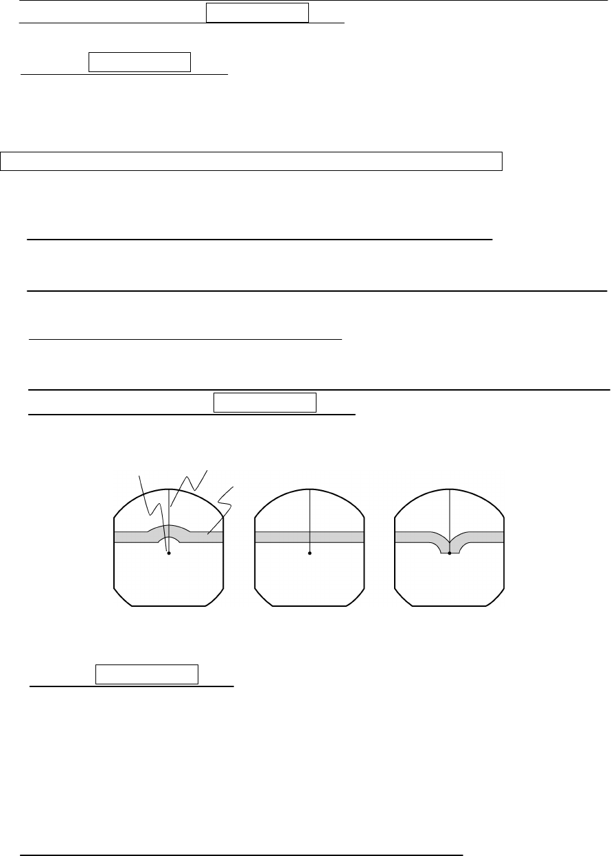
254
(i) Adjust the proximate perimeter of the target to the distance to the VRM pushing the "▲
(up)" or "▼ (down)" on the RANGE
RANGERANGE
RANGE key.
(j) Push the
ENTER
ENTERENTER
ENTER
key.
The 0 NM adjustment has been completed.
Reference:
Reference:Reference:
Reference:
When
WhenWhen
When
there
therethere
there
is
isis
is
no
nono
no
target
targettarget
target
with
withwith
with
known
knownknown
known
distance
distancedistance
distance
from
fromfrom
from
the
thethe
the
ship.
ship.ship.
ship.
If there is no target with known distance from the ship, it is possible to undertake 0 NM
adjustment using the following simplified method.
(A) Steps (a) through (c) are the same as with a target of known distance.
(B) Select a target that represents a long linear line such as the shoreline or embankment.
(C) Same as in (h) with a target of known distance.
(D) Adjust so that the target becomes a straight line on the PPI screen pushing the "▲
(up)" or "▼ (down)" on the RANGE
RANGERANGE
RANGE key.
The distance is too great The distance is just right The distance is too short
(E) Push the
ENTER
ENTERENTER
ENTER
key.
The 0 NM adjustment has been completed.
9.8.5 Setting the antenna height
This operation sets the height of the antenna from the sea surface.
(a) Select "ANTENNA HEIGHT" in the menu "INITIAL SETTING 1".
Position of the ship Ship's heading marker
Target

255
(b) Select the height of the radar antenna among "UNDER 5m", "5m TO 10m", and "MORE
THAN 10m".
9.8.6 Presetting the sensitivity
This operation sets the maximum sensitivity when [GAIN] control is turned.
This adjustment should not be undertaken without reason.
When undertaking this adjustment, also undertake "9.8.2. Adjustment of the Noise Level".
(a) Push the soft key
DISPLAY
DISPLAYDISPLAY
DISPLAY
.
(b) Push the soft key 1 and select
EXP
EXPEXP
EXP
OFF
OFFOFF
OFF
.
(c) Turn the [RAIN] control to the minimum (turn to maximum counterclockwise).
(d) Turn the [SEA] control to the minimum (turn to maximum counterclockwise).
(e) Turn the [GAIN] control to the maximum (turn to maximum clockwise).
This maximizes the strength of the echo on the PPI screen.
(f) Select "GAIN PRESET" in the menu "INITIAL SETTING 1".
(g)
Adjust the sensitivity level pushing the "▲ (up)" or "▼ (down)" on the
RANGE
RANGERANGE
RANGE
key.
(h) Push the
ENTER
ENTERENTER
ENTER
key.
The maximum level of gain has been set.
9.8.7 Presetting the sea clutter
This operation sets the maximum level of suppression when the [SEA] control is turned.
This adjustment should not be undertaken without reason.
(a) Set the range to 0.125NM pushing the "▼ (down)" on the RANGE
RANGERANGE
RANGE key.
(b) Undertake tuning adjustment using the [TUNE] control.
(c) Push the soft key
DISPLAY
DISPLAYDISPLAY
DISPLAY
.

256
(d) Push the soft key 1 and select
EXP
EXPEXP
EXP
OFF
OFFOFF
OFF
.
(e) Turn the [GAIN] control to the maximum (turn to maximum clockwise).
(f) Turn the [RAIN] control to the minimum (turn to maximum counterclockwise).
(g) Turn the [SEA] control to the maximum (turn to maximum clockwise).
The strength of the echo on the PPI screen is maximized with sea surface clutter sup-
pression maximized.
(h) Select "STC PRESET" in the menu "INITIAL SETTING 1".
(i)
Adjust the level of suppression pushing the "▲ (up)" or "▼ (down)" on the
RANGE
RANGERANGE
RANGE
key.
The PPI screen near the center adjusts to the grade projected slightly.
(j) Push the
ENTER
ENTERENTER
ENTER
key.
Suppression of sea surface clutter has been set at the maximum level.
9.8.8 Suppression of main bang
This adjustment is undertaken to suppress main bang that is the reflected signal from
three dimensional circuits such as the wave guide that normally appears at the center of
the radar display as a circle.
Optimum adjustment is achieved when the main bang image remains lightly on the
screen.
This adjustment should not be undertaken without reason. Erroneous adjust-
ment may cause targets that are proximate to be erased from the screen.
(a) Set the range to 0.125NM pushing the "▼ (down)" on the the RANGE
RANGERANGE
RANGE key.
(b) Select "OFF" in the line "PROCESS" - the menu "FUNCTION".
(c) Push the soft key
DISPLAY
DISPLAYDISPLAY
DISPLAY
.
Attention

257
(d) Push the soft key 1 and select
EXP
EXPEXP
EXP
OFF
OFFOFF
OFF
.
(e) Push the the soft key
PROCESS
PROCESSPROCESS
PROCESS
.
(f) Push the soft key 1 and select
AUTO
AUTOAUTO
AUTO
OFF
OFFOFF
OFF
.
(g) Turn the [GAIN] control to the maximum (turn to maximum clockwise).
(h) Turn the [SEA] control to the mid position.
(i) Turn the [RAIN] control to the minimum (turn to maximum counterclockwise).
(j) Select "MBS LEVEL" in the menu "INITIAL SETTING 1".
(k)
Adjust the suppression level pushing the "▲ (up)" or "▼ (down)" on the
RANGE
RANGERANGE
RANGE
key.
(l) Push the
ENTER
ENTERENTER
ENTER
key.
The suppression level of the main bang has been determined.
(
m
) Select "MBS RANGE" in the menu "INITIAL SETTING 1".
(n)
Adjust the suppression range pushing the "▲ (up)" or "▼ (down)" on the
RANGE
RANGERANGE
RANGE
key.
(o) Push the
ENTER
ENTERENTER
ENTER
key.
Adjustment of the suppression range of the main bang has been completed.
9.8.9 Display of simulator image
By activating this function, it is possible to display a demonstration screen on the PPI
screen.
To make the setting of this function effective, the power must be once switched off.
(a) Push the
STBY/OFF
STBY/OFFSTBY/OFF
STBY/OFF
key.
The display will enter the standby mode.

258
(b) Select "INITIAL SETTING 2" in the menu "INITIAL SETTING 1".
(c) Select "ON" in the line "SIMULATOR" - the menu "INITIAL SETTING 2".
9.8.10 Setting the TD reception number
This operation is for selecting the number of the TD (LORAN C time difference) to be
received.
(a) Select "INITIAL SETTING 2" in the menu "INITIAL SETTING 1".
(b) Move the cursor to the extent of the value shown in the "SET TB NUMBER" - the menu
"INITIAL SETTING 2".
(c) Move the location for input by operating the left and right keys of the cross key.
(d) Select the TD number to be received pushing the "▲ (up)" or "▲ (down)"
on the
RANGE
RANGERANGE
RANGE
key.
When the numbers are selected, the following field data of NMEA is displayed.
1: TD1 field of the GTD/GLC sentence.
2: TD2 field of the GTD/GLC sentence.
3: TD3 field of the GTD/GLC sentence.
4: TD4 field of the GTD/GLC sentence.
5: TD5 field of the GTD/GLC sentence.
A: A field of the RMA sentence
B: B field of the RMA sentence

259
9.8.11 GPS/DGPS
1. Initial setting of GPS
1. Initial setting of GPS1. Initial setting of GPS
1. Initial setting of GPS
This operation is for undertaking initial setting of GPS. The GPS receiver measures posi-
tion without initial setting but 10 or more minutes may be required after initial setting.
● Content of settings
Ship position : Approximate latitude and longitude is sufficient
Exclusion satellite : When unhealth satellite is used, precision may deteriorate.
The satellite number input here is not used for measuring the
position.
Geodetic system : Japan is "02"
Antenna height : Input the height of the antenna from the sea surface.
Fix mode : Since the height of the antenna is fix in the case of an ocean
going vessel, greater stability in position is obtained in 2D (two
dimensions).
DOP level : If only position results with high precision are intended to be
used, designate 10 or less or 5 or less.
Position average :
When variance in position needs to be minimized, select
LONG
LONGLONG
LONG
.
When response needs to be maximized select
NONE
NONENONE
NONE
. However,
with this latter setting, variance will increase.
(a) Select "GPS" in the line "GPS PRESET" - the menu "INITIAL SETTING 1".
The menu "GPS" will be displayed.
(b)
Select the items in the cross key and change the set value using the
RANGE
RANGERANGE
RANGE
key.
In order to change the ship's "N/S" or "E/W" position using the left and right keys
of the cross key.
(c) Push the
ENTER
ENTERENTER
ENTER
key.
The setting has been determined.
(d) Select "SEND DATA" in the menu "GPS".
The GPS setting will be implemented.
2. Initial setting of DGPS
2. Initial setting of DGPS2. Initial setting of DGPS
2. Initial setting of DGPS
In the event high precision position determination is intended using DGPS, it is nec-
essary to set the beacon receiver.

260
● Setting mode
MANUAL : This operation sets the frequency and baud rate of the beacon receiver.
This allows receipt of DGPS at an early stage but receipt is not possible
unless the ship is in the beacon receipt area that is set.
AUTO : Automatic search of the beacon transmission station is undertaken for
receipt. Time is required for this search.
(a) Select "DGPS" in the line "GPS PRESET" - the menu "INITIAL SETTING 1".
The menu "DGPS PRESET" will appear.
(b)
Select the items in the cross key and change
the
set value using the
RANGE
RANGERANGE
RANGE
key.
Changing "N/S" and "E/W" of the ship's position is also set pushing the "▲ (up)"
or "▼ (down)" on the
RANGE
RANGERANGE
RANGE
key.
(c) Push the
ENTER
ENTERENTER
ENTER
key.
The setting has been determined.
(d) Select "SEND DATA" in the menu "DGPS PRESET".
The DGPS setting will be implemented.
3. Status of reception of GPS and DGPS
3. Status of reception of GPS and DGPS3. Status of reception of GPS and DGPS
3. Status of reception of GPS and DGPS
This operation displays the status of reception of the GPS receiver and DGPS receiver.
(a)
Select "CONDITION" in the line "GPS PRESET" - the menu "INITIAL SETTING 1".
The status of reception of the GPS receiver and DGPS receiver will be displayed.
The display of the reception status of GPS will display the conditions of the following items
only when the sensor type receiver such as JLR-4310 is connected and operating normally.
● Items
Ship position : When the ship's position is determined, the latitude and lon-
gitude of the position will be displayed.
GPS internal time : The world time as measured by the GPS receiver will be dis-
played.
Altitude : The altitude of the ship will be displayed. However, when
the fix mode is 2D (two dimension), the height of the antenna
that was input at initial setting will be displayed.
DOP : The precision of the results of the measurement will be dis-
played. If the value is 20 or above, the precision is poor.
261
Reception satellite : The number of the satellite used for the measurement will be
displayed.
Bearing, elevation angle
: The bearing and elevation angle of the satellite will be dis-
played.
Signal strength : The strength of the signal of the satellite from which signals
are being received will be displayed. If the value is 20 or
less, the satellite may not be usable for measurements.
The following items will be displayed only when a beacon receiver is connected and
operating normally.
● Items
Frequency : The frequency of the beacon station from which signals are
being received will be displayed.
Baud rate : The baud rate of the beacon station from which signals are
being received will be displayed.
RSSI : The reception strength of the beacon station from which sig-
nals are being received will be displayed. If the value is 100
or less, the beacon may be not possible to receive signals.

262
List of Geodetic Systems
No. Name
0 WGS-84
1 WGS-72
2 Japan
3 North American 1927 (U.S)
4 North American 1927 (Canada & Alaska)
5 European 1950 (Europe)
6 Australian geodetic 1966 (Australia)
7 Ordance Survery of Great Britain (England)
8 NAD-83
9 - (no use)
10 - (no use)
11 ADINDAN (Etiopia & Sudan)
12 ARC 1950 (Botswana)
13 AUSTRALIAN GEODETIC 1984 (Australia)
14 BERMUDA 1957 (the Bermudas)
15 BOGOTA OBSERVATORY (Columbia)
16 CAMPO INCHAUSPE
17 CHATHAM 1971
18 CHUA ASTRO (Paraguay)
19 CORREGO ALEGRE (Brazil)
20 DJAKARTA (VATAVIA) (Sumata)
21 EUROPEAN 1979 (Europe)
22 GEODETIC DATUM 1949 (New Zealand)
23 GUAM 1963 (Guam)
24 HAYFORD 1910 (Finland)
25 HJORSEY 1955 (Ice land)
26 INDIAN (India & Nepal)
27 IRELAND
28 KERTAU 1948 (West Malaysia)
29 L.C.5 ASTRO (Cayman Black Island)
30 LIBERIA 1964 (Liberia)
31 LUZON (Philippines)
32 MERCHICH (Morocco)
33 MINNA (Cameroon)

263
34 NAHRWAN (Oman)
35 NAPARIMA, BWI (Trinidad and Tobago)
36 OLD EGYPTIAN (egypt)
37 OLD HAWAIIAN (the Hawaii Island)
38 PICO DE LAS NIEVES (the Canary Island)
39 PROVISIONAL SOUTH AMERICAN 1956 (South America)
40 PROVISIONAL SOUTH CHILEAN 1963 (Southern Chile)
41 PUETRO RICO (Puerto Rico and V irgin Island)
42 QORNOQ (South Greenland)
43 RT90 (Sweden)
44 SANTA BRAZ (Sao Maguel, Santa Maria Island)
45 SOUTH AMERICAN 1969 (South America)
46 SOUTHWEST BASE (Faial,Graciosa,Pico,Jorge and terceira Island)
47 TIMBALAI 1948 (Brunei and East Malaysia)
264
9.9 Returning to the Initial Setting Conditions
In the event such phenomena as the distorted screen or the keys becoming inoperable
occurs while the radar is in use, the following procedures shall be taken to initialize the
system.
When initialization is undertaken, all setting excluding the menu "INITIAL SET-
TING 1" and "INITIAL SETTING 2" will be reset to the ex-factory shipment condi-
tions.
(a) Push the
STBY/OFF
STBY/OFFSTBY/OFF
STBY/OFF
key and
X-MIT/OFF
X-MIT/OFFX-MIT/OFF
X-MIT/OFF
key simultaneously.
Power is turned off.
(b) Push the
MENU
MENUMENU
MENU
key,
ENTER
ENTERENTER
ENTER
key and
STBY/OFF
STBY/OFFSTBY/OFF
STBY/OFF
key
simultaneously.
Power will be turned on as in normal operation for turning on power.
Attention

265
9.10 Maintenance
9.10.1 General maintenance
It is necessary to perform the maintenance services listed below to keep the radar unit
in good working conditions. Proper maintenance of the radar unit minimizes the possi-
bility of machine failures. The maintenance operations that are common to all compo-
nents of the radar unit are listed below.
1. Cleaning
1. Cleaning1. Cleaning
1. Cleaning
Remove dirt, dust, or water-spray from the radar unit enclosure and keep it as clean as
possible. Use a dry lint-free cloth.
2. Screw inspection
2. Screw inspection2. Screw inspection
2. Screw inspection
Check the screws used to assemble and secure the components of the radar unit for
loose connection.
3. Cabling check
3. Cabling check3. Cabling check
3. Cabling check
Check the cables connecting between the components (between the scanner unit and
display unit, display unit and power supply, and display unit and optional devices) for
poor connection.
WARNING
Before starting maintenance work, be sure to turn off the main power source.
If a rectifier unit is used, in particular, turn off power to the display unit. Note
that voltages from the rectifier unit are always present even if the radar is
stopped. It may result in sereve electric shock or breakdown.
266
9.10.2 Scanner unit
WARNING
When performing maintenance or inspection of the scanner unit, be sure to
shut off the safety switch of the scanner unit after turning off the power of the
display unit. Failure to do this may cause severe electric shock or
breakdown or the sudden movement of the scanner unit may cause bodily
injury or breakdown.
CAUTION
Since the magnetron in the modulator circuit emits strong magnetism, watches
or magnetic cards should not be brought into close proximity of the modulator
circuit. Doing so may cause breakdown and destruction of data contained in
such items.
1. Radiation unit
1. Radiation unit1. Radiation unit
1. Radiation unit
(a) A radiation surface of radiation unit (JMA-2343: Whole surface of the radome cover /
JMA-2344: Front side of radiation unit) contaminated by smoke, dust, or paint would
cause attenuation or reflections of radio waves, resulting in reduced radar performance.
Periodically check the radome scanner unit. If it proves dirty, wipe the radome surface
with a soft lint-free cloth moistened with alcohol or damped cloth.
CAUTION
Never use such solvent as Thinner, Gasoline, Benzen, Trichlene or Kentene
for cleaning. Those solvents deteriorate the surface.
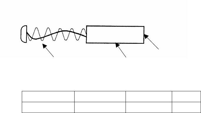
267
2. Rotary drive block (JMA
2. Rotary drive block (JMA2. Rotary drive block (JMA
2. Rotary drive block (JMA-
--
-2344)
2344)2344)
2344)
(a) Lubricating gears
Apply grease to gears evenly using a knife or brush. This lubrication needs to be per-
formed at least semiannually. The shorter the lubrication period, the longer the gears will
endure.
Use Mobilux 2 from Mobile Oil Co., Ltd. or equivalent.
(b) Drive motor (JMA-2344)
(α) Reduction gears
The reduction gears need no lubrication unless it is subject to oil leakage. If
they are disassembled for overhaul, replenish lubricant "Beacon 325" from Esso
Standard.
(β) Motor
The life time of the brush unit is 2,000 hours. The brush needs to be replaced if
1/2 of the overall length is worn.
The commuter needs to be kept clean. If any carbon power fixed on the com-
muter cannot be removed with a dry cloth, burnish it with a sand paper # 150 to
#400.
The carbon brush can be removed by removing the caps located on both sides of
the bottom portion of the motor.
Description Type JRC code Quantity
Carbon Brush 54531-01 BRXP05247 2
(c) Pedestal
Check the scanner unit mounting molts occasionally and apply paint semiannually to
protect them from corrosion.
Carbon brush
Contact with the commuter
Spring

268
9.10.3 Display unit
Cleaning the Display Unit Screen
Cleaning the Display Unit ScreenCleaning the Display Unit Screen
Cleaning the Display Unit Screen
● Dust on the CRT tube would reduce the glass transparency and make the vide
image dim. Wipe the screen surface with a soft lint-free cloth (made of flannel or
cotton). A cloth moistened with an antistatic agent would cause little problem.
When using it, wipe softly; never rub the screen surface with force.