Japan Radio NKE250 Marine Radar User Manual Manual 1 of 4 for CKENKE250
Japan Radio Co Ltd. Marine Radar Manual 1 of 4 for CKENKE250
Contents
- 1. Manual 1 of 4 for CKENKE250
- 2. Manual 2 of 4 for CKENKE250
- 3. Manual 3 of 4 for CKENKE250
- 4. Manual 4 of 4 for CKENKE250
Manual 1 of 4 for CKENKE250

本社事務所
三鷹製作所
〒107-8432
〒181-8510
東京都港区赤坂2丁目17番22号
赤坂ツインタワー本館
電話:03-3584-8711(総務)
ファックス:03-3584-8715
東京都三鷹市下連雀5丁目1番1号
電話:0422-45-9111(案内)
ファックス:0422-45-9110
2002. 8. 初版
JRC
JMA-2343/2344
コード No. 7ZPRD0558
CODE No. 7ZPRD0558
For further information contact :
HEAD OFFICE &
SALES DEPT.
Akasaka Twin Tower (Main),
17-22, Akasaka 2-chome, Minato-ku,
Tokyo, 107-8432 JAPAN
Phone : +81-3-3584-8711
Fax : +81-3-3584-8715
Telex : 0242-5420 JRCTOK J
MAIN PLANT 1-1, Shimorenjaku 5-chome, Mitaka-shi,
Tokyo
181-8510 JAPAN
Phone : +81-422-45-9111
Fax : +81-422-45-9110
Telex : 02822-351 JRCMTK J
FIRST EDITION
AUG. 2002
JRC
I
はじめに
はじめにはじめに
はじめに
このたびは、JRC船舶レーダJMA-2343/JMA-2344をお買い上げいただきま
して、まことにありがとうございます。
本装置は、レーダ信号の送受信部、ブラウン管表示部および空中線等の主要部か
らなる、船舶の安全航行を図るための船舶用レーダ装置です。
● お使いになる前に、この取扱説明書をよくお読みのうえ、正しくお使いくだ
さい。
●
取扱説明書は必要なときに参照できるよう大切に保管してください。
万一、ご使用中にわからないことや不具合が生じたときにお役立てください。
PREFACE
Thank you very much for purchasing the JRC marine radar equipment,
JMA-2343 and JMA-2344.
This equipment is a marine radar equipment designed to obtain safe
operation of marine ships. The equipment consists of a radar signal
transceiver unit, a CRT display unit and a scanner unit as its main units.
● Before operating the equipment, be sure to read this instruction manual
carefully for correct operation.
● Maintain this instruction manual so that operators can refer to it at
anytime.
Refer to this manual when any inconvenience or defect occur.
II
●ご使用の
●ご使用の●ご使用の
●ご使用のまえに●
まえに●まえに●
まえに●
この取扱説明書および製品への表示では、製品を安全に正しくお
使いいただき、あなたや他の人々への危害や財産への損害を未然
に防止するために、いろいろな絵表示をしています。その表示と
意味は次のようになっています。
内容をよく理解してから本文をお読みください。
この表示を無視して、誤った取扱いをすると、人が死亡または重
傷を負う可能性が想定される内容を示しています。
この表示を無視して、誤った取扱いをすると、人が傷害を負う可
能性が想定される内容および物的損害のみの発生が想定される内
容を示しています。
△記号は注意(危険・警告を含む)を促す内容があることを告げる
ものです。
図の中に具体的な注意内容(左図の場合は感電注意)が描かれてい
ます。
記号は禁止の行為であることを告げるものです。
図の中や近傍に具体的な禁止内容(左図の場合は分解禁止)が描か
れています。
●記号は行為を強制したり指示する内容を告げるものです。
図の中に具体的な指示内容(左図の場合は電源プラグをコンセント
から抜け)が描かれています。
絵表示について
絵表示について絵表示について
絵表示について
警告
警告警告
警告
注意
注意注意
注意
絵表示の例
絵表示の例絵表示の例
絵表示の例
警告ラベルについて
警告ラベルについて警告ラベルについて
警告ラベルについて
本製品の上カバーには警告ラベルが貼ってあります。
警告ラベルを取り外したり、破損、改変を絶対にしないでください。
感電注意
分解禁止 禁止
プラグ
を抜け
指示

III
●
●●
●Before Operation●
●●
●
Various pictorial indications are included in this manual and are shown
on these equipment so that you can operate them safely and correctly
and prevent any danger to you and / or to other persons and any damage
to your property during operation. Such indications and their meanings
are as follows.
Please understand them before you read this manual:
This indication is shown where any person is supposed to be in danger of
being killed or seriously injured if this indication is neglected and these
equipment are not operated correctly.
This indication is shown where any person is supposed to be injured or any
property damage is supposed to occur if this indication is neglected and these
equipment are not operated correctly.
The△mark represents CAUTION (including DANGER and WARNING).
Detailed contents of CAUTION ("Electric Shock" in the example on the
left.) is shown in the mark.
The mark represents prohibition.
Detailed contents of the prohibited action ("Disassembling Prohibited" in
the example on the left) is shown in the mark.
The ● mark represents instruction.
Detailed contents of the instruction ("Disconnect the power plug" in the
example on the left) is shown in the mark.
Pictorial Indication
WARNING
CAUTION
Examples of pictorial indication
Warning label
There is a warning label on the top cover of the equipment.
Do not try to remove, break or modify the label.
Electric
Shock
Disassembling
Prohibited
Prohibition
Disconnect the
power plug
instruction
IV
●ご使用上の注意●
●ご使用上の注意●●ご使用上の注意●
●ご使用上の注意●
空中線、送受信機及び指示機の内部には触れないでください。
空中線、送受信機及び指示機の内部には触れないでください。空中線、送受信機及び指示機の内部には触れないでください。
空中線、送受信機及び指示機の内部には触れないでください。
高電圧部により感電の原因となります。機器内部の保守、点検、調整等は当社の営
業部またはお近くの支社・支店・営業所または代理店にサービスを依頼してくださ
い。
当社の営業部・支社・支店・営業所
巻末の「事業所一覧」をご覧ください。
空中線輻射部は回転しますので、近づかないでください。
空中線輻射部は回転しますので、近づかないでください。空中線輻射部は回転しますので、近づかないでください。
空中線輻射部は回転しますので、近づかないでください。
急に空中線が回転し人体を殴打して、負傷する原因となります。
空中線輻射部は人が近づけないよう操舵室の屋根、フライングブリンジ、架台、レ
ーダーマスト等の高い場所に設置することをおすすめします。また、人の近づく恐
れのある場合は空中線ガードを設置することをおすすめします。空中線の作業をす
る場合は、空中線の安全スイッチを切ってください。
空中線は人の頭より高い位置に設置してください。
空中線は人の頭より高い位置に設置してください。空中線は人の頭より高い位置に設置してください。
空中線は人の頭より高い位置に設置してください。
至近距離で直接電波を浴びると人体に影響を及ぼす原因となります。
保守、点検で人がアンテナに接近する場合は指示機の準備
保守、点検で人がアンテナに接近する場合は指示機の準備保守、点検で人がアンテナに接近する場合は指示機の準備
保守、点検で人がアンテナに接近する場合は指示機の準備/
//
/断スイッチを
断スイッチを断スイッチを
断スイッチを
押し、指示機を準備状態にしてください。
押し、指示機を準備状態にしてください。押し、指示機を準備状態にしてください。
押し、指示機を準備状態にしてください。
至近距離で直接電波を浴びると人体に影響を及ぼす原因となります。
警告
警告警告
警告
注意
注意注意
注意
レーダはあくまでも航法援助装置としてご使用ください。
レーダはあくまでも航法援助装置としてご使用ください。レーダはあくまでも航法援助装置としてご使用ください。
レーダはあくまでも航法援助装置としてご使用ください。
また、操船の最終判断は必ず操船者自身で行ってください。
また、操船の最終判断は必ず操船者自身で行ってください。また、操船の最終判断は必ず操船者自身で行ってください。
また、操船の最終判断は必ず操船者自身で行ってください。
操船の最終判断を、レーダが表示する情報のみに頼った場合、衝突、座礁等の事故の
原因となることがあります。
V
●
●●
●
Cautions to be used during operation
●
●●
●
Do not touch the insides of the scanner unit, transceiver and displa
y
unit.
Touching any high voltage area, you will get an electric shock. For
maintenance, inspection and adjustment of internal parts of these equipment,
consult with our sales office or distributor in your district.
Since the scanner unit radiator rotates, do not approach it.
The scanner unit may start rotating suddenly, and consequently any person may
be struck and be injured. We recommend you to install the scanner unit
radiator on the roof of the wheel house, flying bridge, trestle, radar mast or any
other high position so that no person can approach it. When servicing the
scanner unit, set the scanner unit safety button to the OFF position.
Install the scanner unit at any place higher than any person.
If being exposed directly to electric wave at close range, you may suffer adverse
influence.
When approaching the antenna for maintenance or inspection, set
the power button of the display unit to the ST-BY position.
If being exposed directly to electric wave at close range, you may suffer adverse
influence.
WARNING
CAUTION
Use these radar only as assisting devices for navigation.
Also, the officer should make the final decision for maneuvering b
y
himself.
If you make the final decision of maneuvering only on the information which a
radar display, it may become the cause of accidents, such as collision and
stranding.
VI
──
ご使用前に注意して
ご使用前に注意してご使用前に注意して
ご使用前に注意して
いただきたい
いただきたいいただきたい
いただきたい
こと
ことこと
こと
──
高電圧に対する注意
高電圧に対する注意高電圧に対する注意
高電圧に対する注意
無線装置、レーダなどの電子機器の内部には数百から数万ボルトの高電圧が使用されていま
す。通常の操作においてはまったく危険はありませんが、万一、誤って機器内部に触れた場
合非常な危険を伴います。(専門整備員以外の機器内部の保守・点検・調整は禁止)
数万ボルトの高圧では感電即死の危険が大きく、また時により数百ボルトの電圧でも感電死
することがあります。このような危険を防止するには機器の内部に手を入れるとき、必ず電
源スイッチを切って、一端を確実に接地した電源でコンデンサーなどを放電させ、電気の残
っていないことを確めた上で初めて手を内部に入れるようにしてください。この際、乾燥し
た木綿の手袋などを用いればなおいっそう危険防止となります。また左手をポケットに入れ、
両手を同時に用いないことも必要な注意の一つです。感電したときの障害は二次的に大きく
なることがあるので足場もしっかりした所を選ぶことが大切です。感電したときは火傷した
所を完全に消毒して、手当を速やかに行うことが必要です。
電撃の救出上の注意
電撃の救出上の注意電撃の救出上の注意
電撃の救出上の注意
電撃を受けた人を発見した場合、直ちに電源を切り回路を接地してください。回路が直ちに
切れないときは、感電した人をできるだけ早く乾いた板、布などの絶縁物を介して直接感電
した人に触れずに離してください。
感電したとき、頭脳の呼吸中枢に電流が流れると呼吸が急に止まります。衝撃があまりひど
くないときは人工呼吸を行うことにより呼吸を回復します。電撃を受けた人は非常に顔色が
悪くなり、脈が大変弱くなってしまうか、まったく止まってしまうことがあり、人事不省に
なり硬直します。
VII
──
PRECAUTIONS BEFORE OPERATION
──
Cautions for high voltage
High voltages from hundreds volts to tens of thousands volts are to be applied to the
electronic equipment such radio and radar devices. You do not face any danger during
normal operation, but sufficient cares are required for maintenance, inspection and
adjustment of their internal components. (Authorized maintenance personnel alone are
permitted to implement maintenance, check-ups or adjustment of internal components.)
High voltages of tens of thousands volts are so dangerous as to bring an instantaneous
death from electric shock, but even voltages of hundreds volts may sometimes lead to a
death from electric shock. To prevent such an accident, make it a rule to turn off the
power button, discharge capacitors with a wire surely earthed on an end and make sure
that internal parts are no longer charged before you touch any parts inside these devices.
At the time, wearing dry cotton gloves ensures you further to prevent such danger. It is
also a necessary caution to put one of your hands in the pocket and not to use your both
hands at the same time.
It is also important to select a stable foothold always to prevent additional injuries once
you were shocked by electricity. If you were injured from electric shock, disinfect the
burn sufficiently and get it taken care of promptly.
What to do in case of electric shock
When finding a victim of electric shock, turn off the power source and earth the circuit
immediately. If it is impossible to turn off the circuit, move the victim away promptly
using insulators such as dry wood plate and cloth without touching the victim directly.
In case of electric shock, breathing may stop suddenly if current flows to the respiration
center in the brain. If the shock is not so strong, artificial respiration may recover
breathing. When shocked by electricity, the victim will come to look very bad with weak
pulse or without beating, resulting in unconsciousness and rigidity.

VIII
救急処置の方法
救急処置の方法救急処置の方法
救急処置の方法
☆救急処置の留意点
☆救急処置の留意点☆救急処置の留意点
☆救急処置の留意点
電撃を受けた人を危険のない限り動かさずに、直ちに人工呼吸を行わなければなりません。人工呼吸
を始めたらリズムを失わないように続けて行う必要があります。
(1) 事故の発生であわてて患者に触れないこと(救助者が感電します)。
(2) あわてず確実に電源を切り患者を静かに電路より離す。
(3) 周囲の人に知らせる(診療所、病院、医師、119番通報、その他)。
(4) 患者を仰向けに寝かせネクタイ、衣類、バンドを緩める。
(5)(イ)各脈拍に触れてみる。
(ロ)心臓が動いているか否か心臓に耳を当てて確かめる。
(ハ)呼吸しているか否か患者の顔へ手の甲または顔を近づけて確かめる。
(ニ)瞳孔の大きさを調べる。
(6) 患者の口を開け入歯、煙草、ガムなどを取出し、口を開けたまま舌を伸ばしタオルなどを挿入
し舌が喉に引込まれないようにすること(歯をくいしばって口が開かない場合はドライバーな
どで開口しタオルなどをかませる)。
(7) 泡立つ粘液が貯まらないように口をふさぐこと。

IX
FIRST AID TREATMENTS
☆
☆☆
☆ First-aid treatments
As far as the victim of electric shock is not in dangerous condition, do not move him and practice
artificial respiration on him immediately. Once started, it should be continued rhythmically.
(1) Do not touch the victim confusedly as a result of the accident, but the rescuer may also get
an electric shock.
(2) Turn off the power source calmly and certainly and move the victim away quietly from the
electric line.
(3) Call a physician or ambulance immediately or ask someone to call a doctor.
(4) Lay the victim on his back and loosen his necktie, clothes, belt, etc.
(5) a. Examine the victim's pulse.
b. Examine his heartbeat bringing your ear close to his heart.
c. Examine his breathing bringing the back of your hand or your face close
d. Check the size of the pupils of his eyes
(6) Open the victim's mouth and take out artificial teeth, cigarette or chewing gum if any.
Keep his mouth open, stretch his tongue and insert a towel or the like in his mouth to
prevent the tongue from suffocating. (If it is hard to open his mouth due to set teeth, open it
with a screwdriver and insert a towel in this mouth.)
(7) Then, close his mouth so that foaming mucus does not accumulate inside.
X
☆脈拍があり呼吸していない場合の処置
☆脈拍があり呼吸していない場合の処置☆脈拍があり呼吸していない場合の処置
☆脈拍があり呼吸していない場合の処置
(1)患者の顔が後を見る位に顔をそり返らせる(頸部に枕を挿入してもよい)。
(2)下顎を上方に引き上げ気道を広げる(気道拡大)。
(3)患者の鼻をつまみ、術者は深く息を吸い患者の口を完全に塞ぐようにして強く呼気を吹き込む。
再び口を離して息を大きく吸って吹き込む。
1分間に約10回から15回くり返す(鼻腔を塞ぐこと)。
(4)自然に呼吸の起きるのを注意しながら呼吸が戻ったときに止める。
(5)開口困難な場合ゴム、ビニールなどのパイプ状のものを鼻腔に挿入して片方の鼻腔と口を完全に
塞いで息を大きく吸って吹き込む。
(6)患者は気が付くといきなり立つ事がありますが静かに寝かせ、熱いコーヒー、紅茶などを与え暖
かくして安静を保つ(アルコール類は与えてはならない)。
頭部をもたげて口うつし人工呼吸を行う方法
頭部をもたげて口うつし人工呼吸を行う方法頭部をもたげて口うつし人工呼吸を行う方法
頭部をもたげて口うつし人工呼吸を行う方法
XI
☆
☆☆
☆When pulse is beating but breathing has stopped
(1) Tilt the victim's head back as far as this face looks back. (A pillow may be inserted under his
neck.)
(2) Push his jaw upward to open his throat wide (to spread his airway).
(3) Pinch the victim's nostrils and take a deep breath, block his mouth completely with yours
and blow into his mouth strongly. Take a deep breath again and blow into his mouth.
Continue this 10 to 15 times a minute (blocking his nostrils).
(4) Carefully watch that he has recovered his natural breathing and stop practicing artificial
respiration.
(5) If it is difficult to open the victim's mouth, insert a rubber or vinyl tube into one of his
nostrils and blow into it blocking the other nostril and his mouth completely.
(6) When the victim recovers consciousness, he may try to stand up suddenly, but let him lie
calmly and serve him with a cup of hot coffee or tea to keep him warm and quiet. (Never give
him alcoholic drinks.)
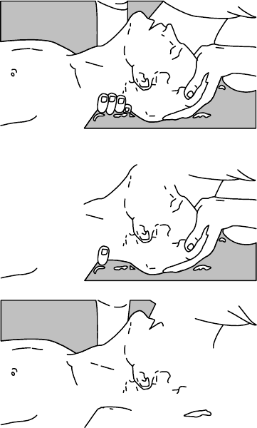
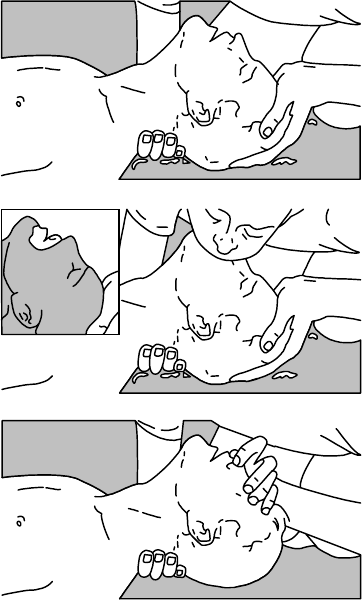
Method of mouth-to-mouth respiration by raising head
Fig.1 Mouth-to-mouth respiration
③
②
①(1) Raise the victim's head. Support his
forehead with one of your hand and his
neck with the other hand. → ①
When you tilt his head backward, the
victim, in most cases, opens his mouth to
the air. This makes mouth-to-mouth
respiration easy.
(2) Cover his mouth as widely as possible
with yours and press your cheek against
his nose → ② , or, pinch his nostrils
with your fingers to prevent air from
leaking. → ③
(3) Blow into his lungs.
Continue blowing into his mouth until his
breast swells. Blow into his mouth as
quickly as possible for the first 10 times.
XII
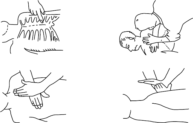
☆脈拍なく呼吸もしていない場合の処置
☆脈拍なく呼吸もしていない場合の処置☆脈拍なく呼吸もしていない場合の処置
☆脈拍なく呼吸もしていない場合の処置
脈拍がなく、瞳孔が開き、心臓に耳を当てても鼓動が聞かれない場合は、心臓が停止しているの
で速やかに人工呼吸を行う必要があります。
(1)胸骨の下1/3の部位に両手を重ね肘を伸ばして(曲げているとくぼむほど押せません)、術者の体
重をかけ約2cm位くぼむように圧迫する(1分間に約50回位くりかえす)。
(心臓マッサージ法)
(2)1人で救急処理を行う場合は、
15回位心臓マッサージを行い速やかに2回呼気を吹き込む。これをくり返す。
2人で救急処理を行う場合は、
1人が5回心臓マッサージを行い、その間に他の1人が1回呼気を吹き込む。これをくり返す。
(心臓マッサージ法と口うつし人工呼吸法の併用)
(3)時々瞳孔を見たり、脈に触れてみる。瞳孔が正常となり脈も規則正しくなったら、各手当てを中
止して様子を見ながらコーヒー、紅茶などを飲ませ暖かくし安静を保つ。いずれにしても、経過
の判断は専門医に任せる。特に、精神的ショックより早く復帰させるように周囲の理解が必要で
す。
①②
③④
図2 心臓マッサージ法
XIII
☆
☆☆
☆When both pulse and breathing have stopped
When no pulse has come not to be felt, his pupils are open and no heartbeat is heard, cardiac
arrest is supposed to have occurred and artificial respiration must be performed.
(1) Place your both hands, one hand on the other, on the lower one third area of his breastbone
and compress his breast with your elbows applying your weight on his breast so that it is
dented about 2cm (repeat compressing his breast 50 times or so a minute).
(Cardiac massage)
(2) In case of one rescuer,
Repeat cardiac massages about 15 times and blow into his mouth 2 times quickly, and repeat
this combination.
In case of two rescuers,
One person repeats cardiac massages 5 times while the other person blows into his mouth
once, and they shall repeat this combination.
(Cardiac massage and mouth-to-mouth respiration)
(3) Examine his pupils and his pulse sometimes. When the both have returned to normal, stop
the artificial respiration, serve him with a cup of coffee or tea and keep him warm and calm
while watching him carefully. Commit the victim to a medial specialist depending on his
condition. To let him recover from the mental shock, it is necessary for persons concerned to
understand his situations and the necessary treatments.
①②
③④
Fig.2 Cardiac massage
XIV
機
機機
機
器
器器
器
外
外外
外
観
観観
観
EQUIPMENT APPEARANCE
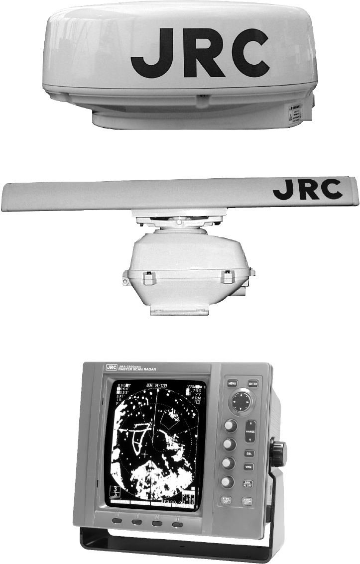
NKE-249形 空中線
Scanner unit Type NKE-249
NKE-250形 空中線
Scanner unit Type NKE-250
NCD-4170形 指示機
Display Unit Type NCD-4170

J
JM
MA
A-
-
2
23
34
43
3
2
23
34
44
4
I
IN
NS
ST
TR
RU
UC
CT
TI
IO
ON
N
M
MA
AN
NU
UA
AL
L
[English edition]
136
Contents
PREFACE ······························································································································I
Before Operation··················································································································III
Cautions to be used during operation·················································································· V
PRECAUTIONS BEFORE OPERATION·········································································· VII
Cautions for high voltage································································································ VII
What to do in case of electric shock ·············································································· VII
FIRST AID TREATMENTS································································································· IX
☆First-aid treatments······································································································ IX
☆When pulse is beating but breathing has stopped······················································ XI
☆When both pulse and breathing have stopped ························································· XIII
EQUIPMENT APPEARANCE ··························································································XIV
Glossary of Radar Terms································································································· 144
Chapter 1 Introduction ······························································· 145
1.1 Function ·········································································································································145
1.2 Features ·········································································································································145
1.3 Composition···································································································································146
1.4 Configuration··································································································································147
1.5 General System Diagram ·············································································································150
Chapter 2 Names and Functions of Control Panel Parts
and Menu Composition ············································ 152
2.1 Functions of the Front Control Panel Keys··················································································152
2.1.1 Functions of the front control panel keys ·············································································152
2.1.2 Composition and functions of the soft key switches····························································153
2.1.3 Functions of the cross key ····································································································154
2.2 Explanation of Screen Readout····································································································156
2.3 Explanation of Functions within the Menu ···················································································158
2.3.1 Menu Composition ················································································································158
2.3.2 Functions within the menu ····································································································160
Chapter 3 Basic Operations ······················································ 164
3.1 Flow of Operations ························································································································164
Soft key operation ···························································································································165
3.1.1 Turning the power ON and starting the system···································································166
1. Turning the power ON···············································································································166
137
2. Undertake transmission ············································································································166
3.1.2 Tuning operation····················································································································166
3.1.3 Adjusting monitoring and image ···························································································167
3.1.4 Data acquisition and monitoring ···························································································167
3.1.5 Ending the operation and shutting down the system ··························································167
1. Interrupting the transmission ····································································································167
2. Shutting the power off ···············································································································167
3.2 Monitoring Standby ·······················································································································168
3.2.1 Changing the brightness of the screen ················································································168
3.2.2 Changing the brightness of the control panel lighting ·························································168
3.2.3 Switching among display languages····················································································168
3.2.4 Setting the buzzer volume ····································································································168
3.3 Basic Operations ···························································································································169
3.3.1 Transmitting ···························································································································169
3.3.2 Interrupting transmission·······································································································169
3.3.3 Changing the range (scale of distance) ···············································································169
3.3.4 Erasing and displaying the fixed range ring·········································································169
3.3.5 Erasing ship's heading marker ·····························································································170
3.3.6 Adjusting the tuning ···············································································································171
3.3.7 Adjusting the sensitivity ·········································································································171
3.3.8 Eradicating radar interference ······························································································172
3.3.9 In the event of rain or snow···································································································173
3.3.10 In case of high waves············································································································174
3.3.11 Measuring the range to the target ························································································175
1. Using VRM·································································································································175
Measuring the distance from the ship using #1VRM ······························································175
Setting whether or not use of #2VRM is enabled····································································175
Operating the #1VRM/#2VRM ·································································································175
Erasing the #1VRM and #2VRM······························································································176
2. Moving the center of the VRM··································································································176
3. Changing the interval between the parallel line cursors ·························································176
4. Using the cross hair cursor ·······································································································176
3.3.12 Changing the range unit········································································································177
3.3.13 Measuring the bearing of a target·························································································177
1. Using EBL··································································································································178
Measuring the distance from the ship using #1EBL································································178
Setting whether or not use of #2EBL is enabled·····································································178
Operating the #1VRM/#2VRM ·································································································178
Erasing the #1EBL and #2EBL ································································································179
2. Moving the center of the EBL ···································································································179
138
3. Changing the interval between the parallel line cursors ·························································179
4. Using the cross hair cursor ·······································································································179
3.3.14 Floating VRM and EBL ·········································································································180
Setting the #1EBL and #1VRM to enable moving ········································································180
Setting the point of reference and center position·········································································180
Operating the EBL and VRM··········································································································180
Canceling the point of reference or center position·······································································180
3.3.15 Using the parallel line cursor·································································································181
The parallel line cursor function is set to #1EBL and #1VRM ······················································181
Operating the parallel line cursor ···································································································181
Canceling the parallel line cursor ···································································································181
3.3.16 Switching the EBL and cursor bearing display among relative, true
and magnetic bearing display mode·····················································································181
Selection of bearing criteria (magnetic bearing, gyrocompass bearing)······································183
Selection of the bearing criteria ······································································································183
3.3.17 Changing the bearing display method of the PPI screen ···················································183
Course setting in course-up mode ·································································································185
3.3.18 Simultaneously measuring the bearing, distance and travel time to the target·················185
Displaying cursor·····························································································································186
Moving the cursor····························································································································186
Erasing the cursor ···························································································································186
3.3.19 L/L display of the cursor ········································································································187
3.3.20 Magnifying the echo images on the PPI screen··································································187
1. Using the image expansion function ························································································187
2. Changing the transmission pulse width ···················································································188
3. Using the zoom function ···········································································································189
Setting the zoom area···············································································································189
Canceling the zoom ··················································································································190
3.3.21 Reducing unnecessary noise and emphasizing the target·················································190
Set the image processing ···············································································································190
Canceling image processing ··········································································································191
3.3.22 Moving the center of the PPI screen ····················································································191
Setting the position to which the center is relocated.····································································191
Canceling center relocation ············································································································192
3.3.23 Controlling power consumption of the radar········································································192
Setting the transmission time ·········································································································192
Setting the standby time ·················································································································192
Commencing timed transmission···································································································192
Canceling timed transmission ········································································································193
Canceling timed transmission while in standby mode ··································································193
139
3.3.24 Locking a fixed target on the radar PPI screen while the ship is navigating······················194
Commencing True Motion display ·································································································194
Canceling true motion display ········································································································195
3.3.25 Monitoring the motion of other ships (Targets)····································································197
1. Radar display of wake···············································································································197
Commencing radar display of a wake······················································································197
Ending radar display of a wake ································································································197
2. Using the lookout alarm ············································································································197
Setting the guard zone··············································································································197
Changing the alarm mode ········································································································199
Eradicating the guard zone·······································································································199
Calling a guard zone ·················································································································199
Changing the sensitivity of the alarm ·······················································································199
3.4 Other Convenient Functions·········································································································200
3.4.1 Displaying the ship's speed on the display unit ···································································200
3.4.2 Displaying the ship's heading on the display unit ································································200
3.4.3 Displaying position information (latitude/longitude, LORAN C time difference)
of the ship and waypoint information (latitude/longitude)·····················································201
Display of position information··································································································201
Erasing location information ·····································································································201
3.4.4 Displaying the waypoint ········································································································202
Display of the waypoint ·············································································································202
Erasing the waypoint·················································································································202
3.5 Miscellaneous Considerations······································································································203
3.5.1 Replacing the battery (BT1)··································································································203
3.5.2 In cases of abnormality during operations ···········································································204
3.6 External Navigation Devices·········································································································205
3.6.1 Obtaining information on bearing ·························································································205
3.6.2 Obtaining information on speed····························································································205
3.6.3 Obtaining information on position·························································································205
3.6.4 Obtaining information on distance to the waypoint······························································206
Chapter 4 How to Interpret the PPI Screen ······························ 207
4.1 Height of and the Distance to the Target ·····················································································207
4.2 Returns from a Target ···················································································································208
4.3 Propagation Path of Radio Waves·······························································································208
4.3.1 Sea returns ····························································································································209
4.3.2 False echoes ·························································································································209
4.4 Display of Radar Transponder······································································································211
140
Chapter 5 Maintenance and Inspection ···································· 212
5.1 General Maintenance····················································································································212
5.2 Scanner Unit ··································································································································213
5.3 Display Unit····································································································································213
5.4 Special Parts··································································································································214
5.5 Circuit Blocks for Repair················································································································214
5.6 Actions to Deal with Abnormalities and Breakdown····································································216
Chapter 6 After-sales Service ··················································· 218
Chapter 7 Disposal ···································································· 220
7.1 Equipment Disposal ······················································································································220
7.2 Disposal of Used Batteries············································································································220
7.3 Disposal of Used Magnetron ········································································································220
Chapter 8 Specifications···························································· 221
8.1 General ··········································································································································221
8.2 Scanner Unit (NKE-249/250)········································································································222
8.3 Display Unit (NCD-4170) ··············································································································224
8.4 Rectifier Unit (NBA-797A) ·············································································································228
8.5 Unit-to-unit Spacing·······················································································································228
Chapter 9 Installation································································· 229
9.1 General ··········································································································································229
9.2 Installing the Scanner Unit ············································································································230
9.2.1 Selecting the installation location··························································································230
9.2.2 Installation procedure ············································································································230
9.2.3 Connection of cables to be assembled················································································233
9.3 Installing the Display Unit··············································································································236
9.3.1 Selecting the installation location··························································································236
9.3.2 Installation procedure ············································································································236
9.3.3 Connecting the power cable ·································································································236
9.3.4 Display unit rear panel···········································································································237
9.3.5 Connection of the external buzzer························································································238
9.3.6 Connecting an electromagnetic compass············································································240
9.4 Modifications to be Made to the Inboard Power Supply ·····························································241
1. Display unit ································································································································241
2. Scanner unit·······························································································································241
9.5 Cable Assemblies··························································································································242
9.5.1 Inter-unit cable (CFQ6774-10/15/20, CFQ6882-10/15/20)·················································242
141
9.5.2 Power cable (CFQ-6776)······································································································243
9.5.3 Selecting a long cable ···········································································································243
9.6 After-installation Adjustments ·······································································································244
9.6.1 Installation-time check···········································································································244
9.6.2 Functional checks··················································································································244
9.6.3 Adjustment items···················································································································244
9.6.4 Rectifier unit ···························································································································245
9.7 Adjustment Procedures·················································································································246
9.7.1 General adjustments ·············································································································246
1. Adjustments to be made when a part is replaced···································································246
2. CRT monitor off center adjustment ··························································································246
3. Adjusting the brilliance level of the CRT monitor screen. ·······················································246
4. Adjusting the focus of the CRT monitor screen·······································································246
9.7.2 Adjusting the scanner unit·····································································································247
1. Adjusting the AVR output voltage from the modulator····························································247
2. Adjusting the tuning indicator level of the receiver ··································································247
9.7.3 Adjusting the display unit ······································································································247
1. Adjusting the brilliance level······································································································247
2. Adjusting the focus of the CRT monitor screen·······································································247
3. Adjusting the tilt angle of the display unit ·················································································248
4. Adjusting the CRT display ········································································································248
5. Adjusting the AVR output voltage ····························································································248
9.8 Initial Settings·································································································································249
9.8.1 Adjustment of the receiver ····································································································250
1. Tune preset································································································································250
2. Adjusting the central frequency ································································································251
3. Adjusting the level of the tune level indicator···········································································251
9.8.2 Adjusting the noise level ·······································································································252
9.8.3 Adjusting the bearing·············································································································252
9.8.4 0 NM adjustment (Initial setting of distance)········································································253
9.8.5 Setting the antenna height ····································································································254
9.8.6 Presetting the sensitivity········································································································255
9.8.7 Presetting the sea clutter ······································································································255
9.8.8 Suppression of main bang ····································································································256
9.8.9 Display of simulator image····································································································257
9.8.10 Setting the TD reception number ·························································································258
9.8.11 GPS/DGPS····························································································································259
1. Initial setting of GPS····················································································································259
2. Initial setting of DGPS·················································································································259
3. Status of reception of GPS and DGPS······················································································260
142
9.9 Returning to the Initial Setting Conditions····················································································264
9.10 Maintenance ··································································································································265
9.10.1 General maintenance············································································································265
1. Cleaning·····································································································································265
2. Screw inspection ·······················································································································265
3. Cabling check ····························································································································265
9.10.2 Scanner unit···························································································································266
1. Radiation unit·····························································································································266
2. Rotary drive block (JMA-2344)·································································································267
9.10.3 Display unit·····························································································································268
Cleaning the Display Unit Screen ··································································································268
143
Attached Figures
【Fig. 101 INTERCONNECTION DIAGRAM OF JMA-2343】
【Fig. 102 INTERCONNECTION DIAGRAM OF JMA-2344】
【Fig. 103 POWER SUPPLY DIAGRAM OF JMA-2343】
【Fig. 104 POWER SUPPLY DIAGRAM OF JMA-2344】
【Fig. 105 INTERNAL CONNECTIONS OF SCANNER UNIT NKE-249】
【Fig. 106 INTERNAL CONNECTIONS OF SCANNER UNIT NKE-250】
【Fig. 107 CIRCUIT DRAWING OF MODULATOR UNIT CME-307】
【Fig. 108-1 CIRCUIT DRAWING OF RECEIVER UNIT CAE-457 (1/2)】
【Fig. 108-2 CIRCUIT DRAWING OF RECEIVER UNIT CAE-457 (2/2)】
【Fig. 109 CIRCUIT DRAWING OF MODULATOR UNIT CME-308】
【Fig. 110-1 CIRCUIT DRAWING OF RECEIVER UNIT CAE-457-1 (1/2)】
【Fig. 110-2 CIRCUIT DRAWING OF RECEIVER UNIT CAE-457-1 (2/2)】
【Fig. 111 INTERNAL CONNECTIONS OF DISPLAY UNIT NCD-4170】
【Fig. 112-1 CIRCUIT DRAWING OF MAIN CONTROL UNIT CMC-1156 (1/4)】
【Fig. 112-2 CIRCUIT DRAWING OF MAIN CONTROL UNIT CMC-1156 (2/4)】
【Fig. 112-3 CIRCUIT DRAWING OF MAIN CONTROL UNIT CMC-1156 (3/4)】
【Fig. 112-4 CIRCUIT DRAWING OF MAIN CONTROL UNIT CMC-1156 (4/4)】
【Fig. 113 CIRCUIT DRAWING OF SOFT KEY PANEL UNIT CCK-872】
【Fig. 114 CIRCUIT DRAWING OF MAIN PANEL UNIT CCK-873】
【Fig. 115 CIRCUIT DRAWING OF POWER SUPPLY UNIT CBD-1596】
【Fig. 116 CIRCUIT DRAWING OF CRT MONITOR UNIT】
【Fig. 117 BLOCK DIAGRAM OF SCANNER UNIT】
【Fig. 118 BLOCK DIAGRAM OF DISPLAY UNIT】

144
Glossary of Radar Terms
A/D Analog to Digital conversion
ACQ Acquisition
A-SEA Automatic Sea surface clutter suppression
A-RAIN Automatic Rain and snow clutter suppression
A-TUNE Automatic Tuning
CPU Central Processing Unit
CRT Cathode-ray Tube
CUP Course-Up
EBL Electronic Bearing Line
EXP Expansion
FTC Fast Time Constant, also known as Rain and snow clutter suppression
GPS Global Positioning System
HUP Head-Up
IR Interference Rejection
L/L Latitude/Longitude
MARPA Mini Automatic Radar Plotting Aid
MH Modulator High Voltage
MOB Man Over Board
NM Nautical Mile
NUP North-Up
PCB Printed Circuit Board
PPI Plan Position Indicator
PROCESS Process
PW Pulse Width
RR Range Rings (Fixed)
RM Relative Motion
SHM Ship’s Heading Marker
STBY Standby
STC Sensitivity time control, also known as Sea surface clutter suppression
TD Time Difference
TM True Motion
TI Trigger
VCT Vector
VD Video
VRM Variable Range Marker
WPT Waypoint
X-MIT Transmit
145
1 Introduction
1.1 Function
The JMA-2243/2344 series radar devices are marine radar devices that use scanner units
including transmitter and receiver and 10 inch monochrome cathode-ray tube utilizing the
compact raster scan method for achieving a fully semi-conductor adopted (excluding special
electron tubes) system.
This equipment comprises radar as defined in the Wireless Telegraphy Act.
1.2 Features
Enhanced fundamental performance of the radar
Through switching among 4 steps in terms of pulse width/cycle switching of frequency and
switching among 3 steps in receiver bandwidth, enhanced fundamental performance of the
radar has been achieved towards display of clearer and higher quality images. Moreover,
through the incorporation of advanced digital signal processing, performance in target de-
tection during increment weather has been improved.
Confirmation of the ship's position and identifying the waypoint at a glance
Through connecting to navigation equipment such as GPS, the location of the ship (nu-
merical value) or a mark on the waypoint may be displayed on the screen and through this,
the difference between the bearing of the waypoint and the ship's heading may be grasped
at a glance.
High operability
EBL and VRM that are frequently used are equipped with dedicated switches. Moreover,
4 soft key switches have been incorporated and functions that are relatively frequently used
may be operated with ease. Additionally, a system for selecting functions that are infre-
quently used from the menu has been adopted.

146
1.3 Composition
Composition of the Radar and Ship Internal Power Source
Comprehensive type
Scanner unit Display unit Ship internal power source
JMA-2343
JMA-2344
NKE-249
NKE-250 NCD-4170 DC (12V/24V/32V)
or
AC(Note) (100V/110V/115V/
200V/220V/230V)
50/60Hz single phase
Rectifier type (option) NBA-797A
(Note) When AC power source is used, the optional rectifier is required.
Accessories
Product Name Quantity JRC Code Remarks
Instruction Manual 1 7ZPRD0558 This manual
CFQ6774-15
(JMA-2343)
10 core composite cable
15m
Cable between the scanner
unit and display unit 1 CFQ6882-15
(JMA-2344)
14 core composite cable
15m
Power cable assembly 1 CFQ-6776 2m
Sun shield 1 MTV303344 -
Standard spare parts kit (7ZXRD0008)
Product name (type) Quantity JRC Code Remarks
Fuse (SB3.15) 2 5ZFAD00382 (for 24/32V) 3.15A
Fuse (SB6.3) 3 5ZFAD00540 (for 12V) 6.3A
Fuse (SB5) 2 5ZFAD00364 (for 24/32V) 5A
Fuse (SB10) 3 5ZFAD00539 (for 12V) 10A
Optional
Product Name Quantity JRC Code Remarks
CFQ6774-10
(JMA-2343)
10 core composite cable
10m
CFQ6774-20
(JMA-2343)
10 core composite cable
20m
CFQ6882-10
(JMA-2344)
14 core composite cable
10m
Cable between the scanner
unit and display unit
1
CFQ6882-20
(JMA-2344)
14 core composite cable
20m
147
1.4 Configuration
Fig. 1.1 OUTLINE DRAWING OF SCANNER UNIT NKE-249
148
Fig. 1.2 OUTLINE DRAWING OF SCANNER UNIT NKE-250
149
Fig. 1.3 OUTLINE DRAWING OF DISPLAY UNIT NCD-4170
150
1.5 General System Diagram
Fig. 1.4 GENERAL SYSTEM DIAGRAM OF JMA-2343
SCANNER UNIT NKE-249
空中線 NKE-249
DISPLAY UNIT NCD-4170
指示機 NCD-4170
COMPASS
250V-TTYCYS-1
CFQ-6776(2m) 8.0φ(max) (JRC SUPPLY)
CFQ-6776(2m) 最大 8.0φ (JRC 支給)
NOTES:
ELIMINATING THE INTERFERENCE ON FREQUENCIES USED FOR MARINE COMMUNICATIONS
AND NAVIGATION DUE TO OPERATION OF THE RADAR.
ALL CABLES OF THE RADAR ARE TO BE RUN AWAY FROM THE CABLES OF RADIO EQUIPMENT.
(EX. RADIOTELEPHONE.COMMUNICAITONS RECEIVER AND DIRRECTION FINDER.ETC.)
ESPECIALLY INTER-WIRING CABLES BETWEEN SCANNER UNIT AND DISPLAY UNIT OF THE
RADAR
SHOULD NOT BE RUN PARALLEL WITH THE CABLES OF RADIO EQUIPMENT.
ご注意
レーダの動作が他の無線装置に、雑音妨害を与えることを防止するために、レーダケーブル、
特に空中線ケーブルを他の無線装置のケーブルと平行に設置しないでください。
250V-TTYCYS-1
GPS
REMOTE MONITOR
250V-TTYCYS-1
JRC SUPPLY:CFQ6774-15 12.0φ(max)
CFQ6774-15 最大 12.0φ(JRC 支給)
10-CORES COMPOSITE CABLE
10 芯シールド付複合ケーブル
250V-TTYCYS-1
NMEA
SHIP'S MAIN(船内電源)
DC 10.8~42V
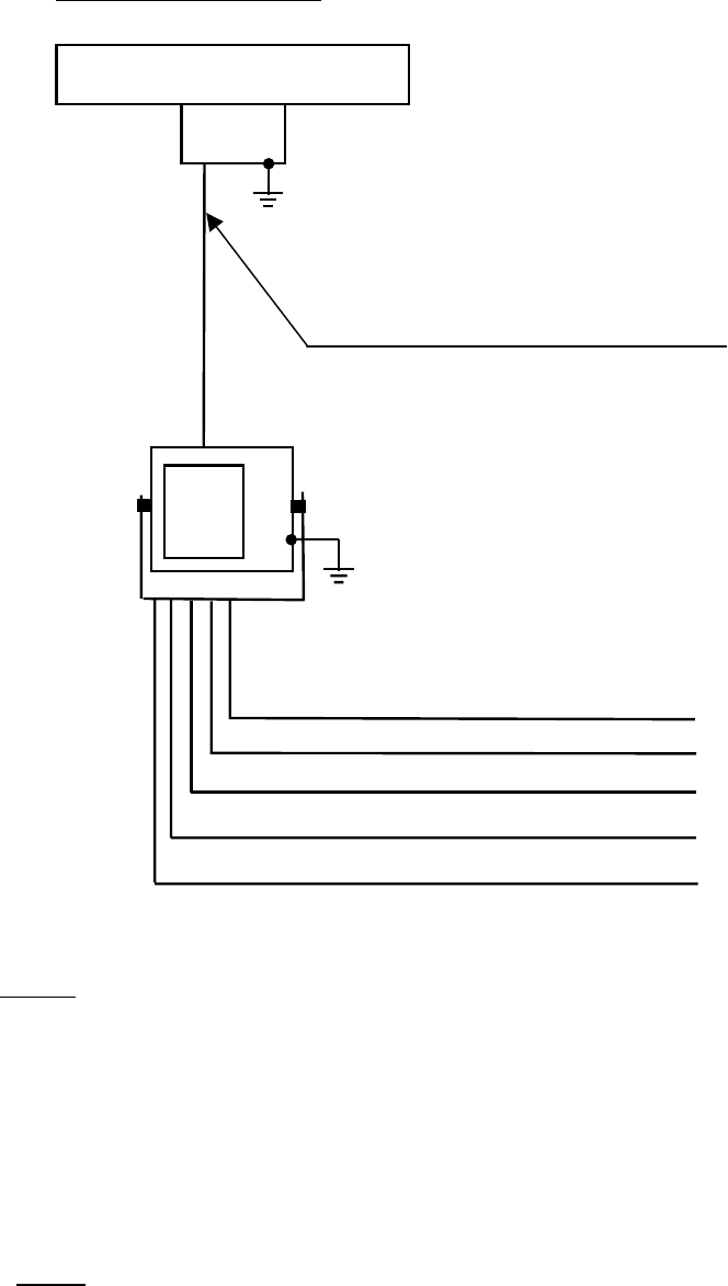
151
Fig. 1.5 GENERAL SYSTEM DIAGRAM OF JMA-2344
JRC SUPPLY:CFQ6882-15 12.0φ(max)
CFQ6882-15 最大 12.0φ(JRC 支給)
SCANNER UNIT NKE-250
空中線 NKE-250
DISPLAY UNIT NCD-4170
指示機 NCD-4170
14-CORES COMPOSITE CABLE
14 芯シールド付複合ケーブル
NOTES:
ELIMINATING THE INTERFERENCE ON FREQUENCIES USED FOR MARINE COMMUNICATIONS
AND NAVIGATION DUE TO OPERATION OF THE RADAR.
ALL CABLES OF THE RADAR ARE TO BE RUN AWAY FROM THE CABLES OF RADIO EQUIPMENT.
(EX. RADIOTELEPHONE.COMMUNICAITONS RECEIVER AND DIRRECTION FINDER.ETC.)
ESPECIALLY INTER-WIRING CABLES BETWEEN SCANNER UNIT AND DISPLAY UNIT OF THE
RADAR
SHOULD NOT BE RUN PARALLEL WITH THE CABLES OF RADIO EQUIPMENT.
ご注意
レーダの動作が他の無線装置に、雑音妨害を与えることを防止するために、レーダケーブル、
特に空中線ケーブルを他の無線装置のケーブルと平行に設置しないでください。
COMPASS
250V-TTYCYS-1
CFQ-6776(2m) 8.0φ(max) (JRC SUPPLY)
CFQ-6776(2m) 最大 8.0φ (JRC 支給)
250V-TTYCYS-1
GPS
REMOTE MONITOR
250V-TTYCYS-1
250V-TTYCYS-1
NMEA
SHIP'S MAIN(船内電源)
DC 10.8~42V
152
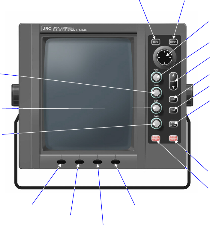
2 Names and Functions of Control Panel Parts
and Menu Composition
2.1 Functions of the Front Control Panel Keys
Normal operations with respect to this radar equipment may be undertaken from the front
panel of the display. Moreover, by using functions that are defined by the menu, the op-
erator may make full use of the functions of this equipment.
While the operations are simple, in order to display the necessary information on the
cathode-ray tube, it is important that the operator has full understanding of the functions of
the various operations.
2.1.1 Functions of the front control panel keys
Sea surface
clutter sup-
pression
Rain and snow
clutter sup-
pression
Open a menu Various settings
Tune adjustment
Cross key
Range
EBL
VRM
Brilliance/
Ship’s head line off
Transmit/Off
Stand-by/Off
Soft key 1 Soft key 4
Soft key 2
Soft key 3
Sensitivit
y
adjustment
153
2.1.2 Composition and functions of the soft key switches
In order to simplify operations, this equipment is equipped with 4 soft key switches on the
front panel. The optional items corresponding to each soft key is displayed at the lower-
most part of the screen and the function may be executed by pushing the corresponding key.
The soft key menu is comprised as follows.
Key1
DISPLAY Key1 : EXP OFF EXP ON
Key2 : CENTER OFFCENT
Key3 : RR OFF RR ON
Key4 : CUR OFF CUR ON
Key2
PROCESS Key1 : AUTOOFF A―SEA A-RAIN
Key2 : IR OFF IR 1 IR 2
Key3 : M-TUNE A-TUNE
Key4 : WKS-OFF WKS-15S WKS-30S WKS-1M
WKS-3M
WKS-CNT WKS-30M WKS-15M WKS-6M
Key3
GUARD
Key1 : MAKE
Key2 : ALM OFF ALM ON
Key3 : SENS1 SENS2 SENS3 SENS4
SENS7
SENS6 SENS5
Key4 : ALM IN ALM OUT
154
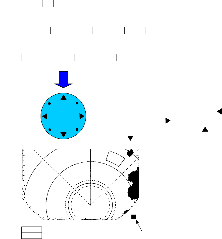
2.1.3 Functions of the cross key
The cross key is used to move the cross cursor, rotate the EBL, change the size of the VRM
and select items from the menu. By pushing the cross key, the cursor moves in the direc-
tion pushed and the EBL may be rotated.
The cross key is used to activate the following functions.
Dedicated key operations
VRM 、 EBL 、 MENU
Soft key operations
OFF CENT、 CUR ON 、 GUARD-MAKE
Menu operations
MENU-FUNCTION-ZOOM SET
Push the cross key
BL rotates in the counterclockwise direction with <
and clockwise direction with .
The VRM distance becomes larger with and
smaller with .
The current cross key mode is shown a
t
the lower right hand corner of the screen.
V
12
1212
12
2
22
2

155
Use Mode Name
Letter on Screen of
Lower Reight Corner
Enables a EBL EBL mode E
Enables a VRM VRM mode V
Enables a F EBL/VRM F EBL/VRM mode F
Enables the parallel line mode Parallel line mode P
Enables the cursor Cursor mode C
Enables the off center mode Off center mode O
Enables the zoom mode Zoom mode Z
Enables the guard mode Guard mode G
Enables the menu mode MENU mode M

156
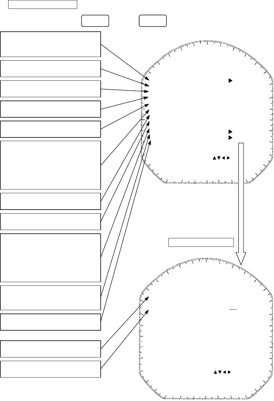
2.2 Explanation of Screen Readout
RNG 09.3
BRG 340° N 35°15.01
POSN
1
11
1045°
045°045°
045°
EBL1R RM H-UP T006°M
2
22
2315°
315°315°
315°
1
11
11.75
1.751.75
1.75
VRM1 NM
2
22
22.25
2.252.25
2.25
12
1212
12
2
22
2
DISPLAY
WP
00:54
A
E139°47.05
SPD 10.2
E
PROCESS GUARD
ALM
I
4
44
44
X2
EBL number Motion mode
EBL bearing display mode
PPI bearing screen display mode
Ship’s heading bearing
Bearing reference
Ship’s bearing data gathering terminal
#1 EBL bearing
#2 EBL bearing
Target expander on
Intereference rejection on
Image process
Waypoint display
Zoom center position
Fixed range ring
#2 EBL
Bearing tick
Zoom mode on
Range
Range ring interval
#1VRM range
#2VRM range
VRM number
Guard zone on
Alarm sensitivity
Alarm mode
Echo generated
by a target
Guard zone
#1EBL
#1 VRM
#2 VRM
Brilliance level
(This mark is displayed
temporarily, when BRI
L
key is pushed.(Level 6))
Tune mode indicator
(When 'A' is displayed on
the indicator right, auto
tune mode is on.)
Center of PPI image
(The center is off set be-
cause the zoom mode is on.)
Cross key mode
(EBL mode)
Soft key item
(1st. layer)
AS
A
S (Automatic Sea surface
clutter suppression)
AR (Automatic Rain and snow
clutter suppression)
EXP
IR
P
157
Distance from the ship to the cursor
12
1212
12
2
22
2
BRG 340°
RNG 09.3
WP
A
N 35°15.01
E139°47.05
POSN
SPD 10.2
346°
C
CUR
4.96
0:29
X2
Azimuth of the cursor position
Travel time to cursor position
Cursor mode on
Cross key mode
(cursor mode)
Azimuth of
the waypoint
Distance to the
waypoint
Requires travel time
to the waypoint
Ship's speed
Location (L/L) data display
(ship location display mode)
Select location display of ship, curso
r
or waypoint from the menu
Waypoint data display
00:54

158
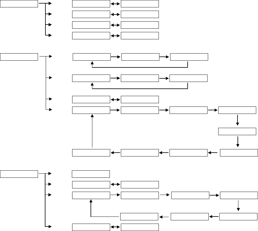
2.3 Explanation of Functions within the Menu
This radar equipment has, in addition to the capability of operating using the front panel
keys (including the soft key), the following operating functions. In this section, the compo-
sition, function and method of setting the menu will be explained.
2.3.1 Menu Composition
With this radar equipment, it is possible to switch the screen display from the Japanese
language, to the English language and to other languages (Chinese, French, Spanish, Ital-
ian, Norwegian, German and Korean).
● Please refer to "3.2.3 Switching Language Display" for the switching among lan-
guages.
SELECT W/CROSS KEY’ ( ) SELECT W/CROSS KEY’ ( )
MENU
FUNCTION
DISPLAY
RADAR SET-UP 1
RADAR SET-UP 2
NEXT
NEXT
NEXT
NEXT
SELECT W/CROSS KEY’ ( )
PRESS CROSS KEY ( )
PRESS MENU TO RETURN
FUNCTION
EBL1/EBL2
EBL2
VRM2
EBL READOUT
ZOOM
TM/RM
HDG MODE
PROCESS
FIX FLOAT
PLINE1 PLINE2
NO YES
NO YES
REL TRUE,MAG
OFF SET
RM TM
H-UP N-UP C-UP
OFF PR1 PR2
DISPLAY
POSITION
WAYP O IN T
RANGE
TIMED TX
TX PERIOD
STBY PERIOD
OFF L/L TD
CUR L/L
WPT L/L
OFF ON
NM KY KM
OFF ON
10 20 30 SCAN
3 5 10 15 MIN
RADAR SET-UP 1
BUZZER
TX PILSE
(1.5NM)
(3NM)
(6NM)
0 1 2 3 4 5 6 7
0 1 2 3 4 5 6 7
0.08 0.25 μs
0.25 0.5 μs
0.5 1.0 μs
DIMMER
BEARING TRUE MAG
MENU
MENUMENU
MENU
PRESS MUNU TO RETURN
PRESS ENT TO SET
SELECT W/CROSS KEY’ ( )
PRESS MUNU TO RETURN
PRESS ENT TO SET
PRESS MUNU TO RETURN
PRESS ENT TO SET
SELECT W/CROSS KEY’ ( )
RADAR SET-UP 2
LANGUAGE ENGLISH 日本語
中文 FRANCAIS
ESPANYOL ITALIANO
NORSK DEUTSCH
PRESS MUNU TO RETURN
PRESS ENT TO SET
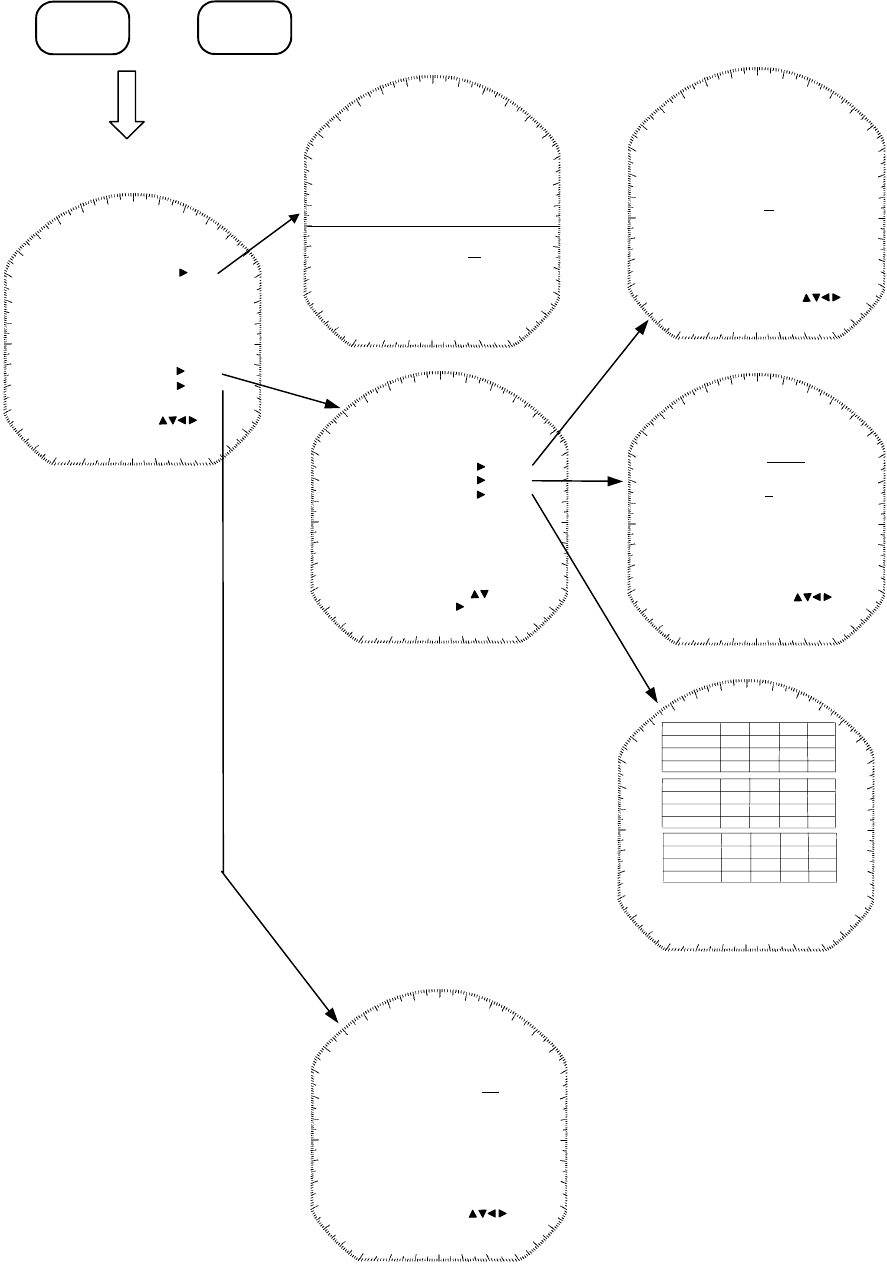
159
Initial Setting Menu
SELECT W/CROSS KEY’ ( )
SELECT W/CROSS KEY’ ( )
SELECT W/CROSS KEY’ ( )
SELECT W/CROSS KEY ( )
SELECT W/CROSS KEY’ ( )
+
++
+
Push those keys simultaneously.
MENU
MENUMENU
MENU
ENTER
ENTERENTER
ENTER
CONDITION
DOP:
VERSION:
ALITUDE:
RSSI[BEACON]:
DATE/TIME:21 JAN 2002
SAT NO.
ELV.
AZIMUTH
SNR
(UTC) 11:14
GPS
DGPS PRESET
MODE
FREQUENCY
BAUD RATE
SEND DATA
MANUAL AUTO
200.0kHz
50 100 200
GPS PRESET
GPS NEXT
CONDITION NEXT
DGPS NEXT
INITIAL SETTING 2
SIMULATOR OFF ON
INITIAL SETTING 1
RECEIVER ADJUST NEXT
DISPLAY TIMING
MBS LEVEL
COMPARATOR PRESET
STC PRESET
ANTENNA HEIGHT
1024
128
128
128
128
UNDER 5m
BEARING
MBS RANGE 128
GAIN PRESET 128
GPS PRESET NEXT
INITIAL SETTING 2 NEXT
GPS
POSITION
ANTENNA HEIGHT
GEODETIC
FIX MODE
DOP LEVEL
POSN AVARAGE
EXCUSION SAT.
SEND DATA
N 35°00.00
15
2D 3D FIX
43
UP TO 5 UP TO 10 UP TO 20
LONG STANDARD NONE
W 135°00.00
00 01 02 03 04 05
SET TD NUMBER 1 2
MOTOR ON OFF
TUNE FREQUENCY 50
TUNE PRESET 128
TUNE LEVEL IND. 50
PRESS MUNU TO RETURN
PRESS ENT TO SET
PRESS MUNU TO RETURN
PRESS ENT TO SET
PRESS MUNU TO RETURN
PRESS CROSS KEY ( )
PRESS MUNU TO RETURN
PRESS ENT TO SET
PRESS MUNU TO RETURN
PRESS ENT TO SET
SAT NO.
ELV.
AZIMUTH
SNR
SAT NO.
ELV.
AZIMUTH
SNR
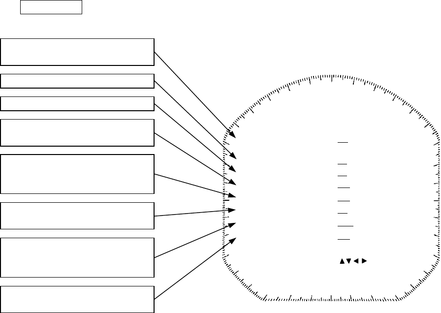
160
2.3.2 Functions within the menu
When using functions marked with [*], connectivity to an external navigation
system is required.
FUNCTION
Select the operating function
of EBL1 and VRM1.
Select use of EBL2.
Select use of VRM2.
Display any random portion o
f
the PPI image enlarged to
twice the original image.
Select read for the azimuth
value of EBL.
* Select "relative" or "true"
motion display.
* Select the method of dis-
playing the bearing of the
PPI screen.
Select the correlative process-
ing of the radar echo.
FUNCTION
EBL1/EBL2
EBL2
VRM2
EBL READOUT
ZOOM
TM/RM
HDG MODE
PROCESS
FIX FLOAT
PLINE1 PLINE2
NO YES
NO YES
REL TRUE,MAG
OFF SET
RM TM
H-UP N-UP C-UP
OFF PR1 PR2
SELECT W/CROSS KEY’ ( )
PRESS ENT TO SET
PRESS MUNU TO RETURN
161
DISPLAY
Select the units for the dis-
tance measured by the VRM or
cursor.
NM : Nautical miles
KY : Kilo yards
KM : Kilometers
* Display the waypoint on
the PPI screen.
The duration of the transmis-
sion mode time is set based on
the rotation of the scanner
unit.
For energy saving purposes,
transmission mode and
standby mode are automati-
cally switched.
Set the duration of the standby
time.
DISPLAY
POSITION
WAYPOINT
RANGE
TIMED TX
TX PERIOD
STBY PERIOD
OFF L/L TD
CUR L/L
WPT L/L
OFF ON
NM KY KM
OFF ON
10 20 30 SCAN
3 5 10 15 MIN
SELECT W/CROSS KEY’ ( )
PRESS ENT TO SET
PRESS MUNU TO RETURN
* Select the information to be
displayed on the screen
from the positional infor-
mation of the ship's head-
ing (latitude/longitude; L/
L
or time difference; TD) or
the location information o
f
the waypoint.

162
RADAR SET-UP 1
RADAR SET-UP 2
Set the buzzer sound.
The sound becomes louder as the
value becomes larger.
Set the lighting of the operation
panel.
The panel becomes brighter as
the value becomes larger.
Set the pulse width.
Settings may be selected from
1.5NM, 3NM or 6NM.
・ The smaller the width, the
greater the resolution will be.
・ The wider the width, the
greater the sensitivity will be.
Set the language of the letters on
the display.
Selection may be from amon
g
the following.
English, Japanese
Chinese, French
Spanish, Italian
Norwegian, German
Korean
Select the azimuth data to be
adopted.
RADAR SET-UP 1
BUZZER
TX PILSE
(1.5NM)
(3NM)
(6NM)
0 1 2 3 4 5 6 7
0 1 2 3 4 5 6 7
0.08 0.25 μs
0.25 0.5 μs
0.5 1.0 μs
SELECT W/CROSS KEY’ ( )
PRESS ENT TO SET
PRESS MUNU TO RETURN
DIMMER
BEARING TRUE MAG
RADAR SET-UP 2
LANGUAGE ENGLISH 日本語
中文 FRANCAIS
ESPANYOL ITALIANO
NORSK DEUTSCH
SELECT W/CROSS KEY’ ( )
PRESS ENT TO SET
PRESS MUNU TO RETURN
163
INITIAL SETTING 1
This menu appears when the MEN
U
key and ENTER key are pushed simultaneously.
INITIAL SETTING 1
RECEIVER ADJUST
DISPLAY TIMING
GAIN PRESET
COMPARATOR PRESET
STC PRESET
ANTENNA HEIGHT
GPS PRESET
INITIAL SETTING 2
1024
128
128
128
128
UNDER 5m
SELECT W/CROSS KEY’ ( )
PRESS ENT TO SET
PRESS MUNU TO RETURN
BEARING
MBS LEVEL
MBS RANGE 128
128
A
djust the criterion level when
the radar image signal is A/D.
A
djust the maximum sensitivit
y
when the GAIN control is
turned fully to the right (maxi-
mum sensitivity).
Normally, the maximum is set
at 255.
A
djust the distance of the image
on the PPI screen.
A
djust the bearing of the image
on the PPI screen.
Implement various adjustments
on the receiver (including rough
tuning adjustment)
A
djust the strength of the sea
surface clutter suppression.
Select the height to the scanner
unit as follows: 5m or less/ 5 to
10m/ 10m or more.
It optimizes the characteristics
of the sea surface clutter sup-
pression by this setting.
When connected to an external
GPS, set the initial value of the
GPS.
A
djust the strength of the main
bang suppression.
A
djust the range of the main
bang suppression.
INITIAL SETTING 2
SIMULATOR
SELECT W/CROSS KEY’ ( )
PRESS ENT TO SET
PRESS MUNU TO RETURN
OFF ON
Display the PPI screen for
demonstration purposes.
Display the menu "INITIA
L
SETTING 2".
INITIAL SETTING 2
SET TD NUMBER
Set the time differential receipt
number.
NEXT
NEXT
NEXT
1 2
164
3 Basic Operations
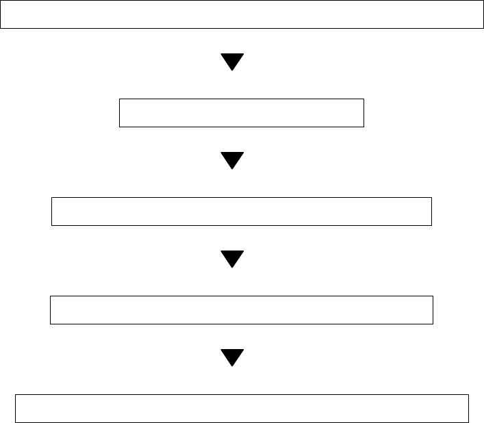
3.1 Flow of Operations
Turning the power on and starting the system
Adjusting the turning
Adjusting the monitoring and video
Data acquisition and measurement
Ending operation and stopping the system
Basic operations are explained on the following pages
165
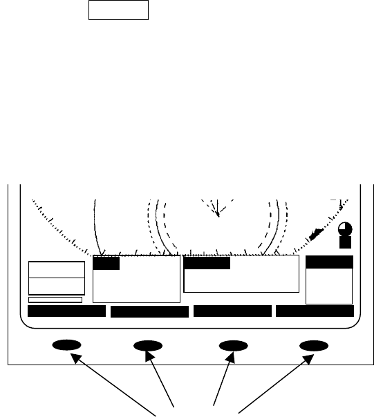
Soft key operation
The basic operations using the soft key are as follows.
From among the 4 switches that are positioned below the screen, push the switch that
corresponds to the required function. The items are displayed at the lower part of the
screen and the required setting may be undertaken by pushing the switch that corre-
sponds to the desired items.
Push the MENU
MENUMENU
MENU key to return to the lowermost tier item.
WP
12
1212
12
2
22
2
BRG 340°
DISPLAY
RNG 09.3
00:54
A
N 35°15.01
E139°47.05
POSN
SPD 10.2
E
PROCESS GUARD
X2
346°
CUR
4.96
0:29
Soft Keys
166
3.1.1 Turning the power ON and starting the system
1
11
1. Turning the power ON
. Turning the power ON. Turning the power ON
. Turning the power ON
In order to turn the power on, push the STBY/OFF
STBY/OFFSTBY/OFF
STBY/OFF
key.
When the power is turned on, a count down timer is displayed on the screen and the
system enters the standby state after 1 minute and 30 seconds.
Moreover, cumulative energized time and cumulative transmission time are also dis-
played. This is used as an indicator for when maintenance is required. Time displays
may incorporate some small errors.
2. Undertake transmission
2. Undertake transmission2. Undertake transmission
2. Undertake transmission
In order to transmit from the standby mode, push the X-MIT/OFF
X-MIT/OFFX-MIT/OFF
X-MIT/OFF
key.
When returning from the transmission mode to the standby mode, push the
STBY/OFF
STBY/OFFSTBY/OFF
STBY/OFF
key.
3.1.2 Tuning operation
The tuning operation of this radar equipment may be undertaken manually or
automatically. Switching between manual operation and automatic operation is
undertaken using the soft key. In the case of automatic tuning, the letter "A" will be
displayed at the right of the lower left hand tune level indicator.
(a) Switching tuning modes
Push the soft key PROCESS
PROCESSPROCESS
PROCESS
.
Each time key 3 is pushed, the mode sequentially changes between A
AA
A-
--
-TUNE
TUNETUNE
TUNE
and M
MM
M-
--
-TUNE
TUNETUNE
TUNE
and if the manual mode is preferred, key 3 should be pushed so
that M
MM
M-
--
-TUNE
TUNETUNE
TUNE
is selected.
(b) Turn the [TUNE] control
In the case of manual tuning, rotate the [TUNE] control on the operation panel to
maximize the size of the image. The tune level indicator acts as an indicator when
undertaking manual tuning and should be adjusted so that the indicator is at the
maximum position.
In the case of automatic tuning, there is no need to turn the [TUNE] control.
In the event no image appears, turn the [GAIN] control on the control panel all the
way to the right and set [SEA] control and the [RAIN] control furthermost to the left.
167
3.1.3 Adjusting monitoring and image
Display the optimal image by adjusting the [TUNE] control (in the case of manual
tuning), [GAIN] control, [SEA] control and [RAIN] control on the control panel.
The range of monitoring distance may be switched by pushing the "▲ (up)" or "▼
(down)" of on RANGE
RANGERANGE
RANGE
key.
The distance range currently selected will be displayed at the lower left hand corner of
the display (please refer to "2.2 Explanation of Screen Readout").
3.1.4 Data acquisition and monitoring
Please refer to "3.3 Basic Operations" and "4 How to Interpret the PPI Screen" for the
various operations.
3.1.5 Ending the operation and shutting down the system
1. Interrupting the transmission
1. Interrupting the transmission1. Interrupting the transmission
1. Interrupting the transmission
(a) Push the STBY/OFF
STBY/OFFSTBY/OFF
STBY/OFF
key.
The transmission will be interrupted and the display will return to the standby mode.
2. Shutting the power off
2. Shutting the power off2. Shutting the power off
2. Shutting the power off
(a) Push the X-MIT
X-MITX-MIT
X-MIT
key and the STBY/OFF
STBY/OFFSTBY/OFF
STBY/OFF
key simultaneously.
The radar will stop operation and all functions will shut down.
WARNING
When performing such work as maintenance, shut the power off and dis-
connect the power connector between the rectifier and the display to cease
supply of electricity to the system.
Even if the power switch is off, electricity may be flowing internally in the
various equipments and performing maintenance and repair under such
conditions may cause accidents such as severe electric shock or equipment
breakdown.

168
3.2 Monitoring Standby
3.2.1 Changing the brightness of the screen
(a) Push the BRIL/HL
BRIL/HLBRIL/HL
BRIL/HL
OFF
OFFOFF
OFF key.
Each time this key is pushed, the brightness of the screen increases by a step.
When the brightness is at the 8th step (maximum) and if the switch is again pushed,
the brightness will be reduced by one step. When the power is turned on, the
brightness level is set at "7".
3.2.2 Changing the brightness of the control panel lighting
(a) Select levels "0" through "7" in the line "DIMMER" - the menu "RADAR SET-UP 1".
The higher the selected number, the brighter the lighting.
(b) Push the MENU
MENUMENU
MENU key.
Menu setting has been completed.
3.2.3 Switching among display languages
The language display on the screen may be switched among English, Japanese and
other languages (Chinese, French, Spanish, Italian, Norwegian, German and Korean).
(a) Select the desired language in the line "LANGUAGE" - the menu "RADAR SET-UP 2".
(b) Push the MENU
MENUMENU
MENU key.
The menu setting has been completed.
3.2.4 Setting the buzzer volume
(a) Select levels "0" through "7" in the line "BUZZER" - the menu "RADAR SET-UP 1".
The higher the selected number, the louder the buzzer.
(b) Push the MENU
MENUMENU
MENU key.
The menu setting has been completed.

169
3.3 Basic Operations
3.3.1 Transmitting
(a) Push the X-MIT/OFF
X-MIT/OFFX-MIT/OFF
X-MIT/OFF key.
The system will switch from standby mode to transmission mode.
3.3.2 Interrupting transmission
(a) Push the STBY/OFF
STBY/OFFSTBY/OFF
STBY/OFF key.
The system will switch into standby mode and the legend "Standby" will appear on the
screen.
3.3.3 Changing the range (scale of distance)
(a) Push the RANGE
RANGERANGE
RANGE key.
Pushing the "▲(up)" key increases the scale of distance.
Pushing the "▼(down)" key decreases the scale of distance.
3.3.4 Erasing and displaying the fixed range ring
(a) Push the soft key DISPLAY
DISPLAYDISPLAY
DISPLAY .
(b) Push the soft key 3 and when erasing the scale, select RR
RRRR
RR
OFF
OFFOFF
OFF and when
displaying, select RR
RRRR
RR
ON
ONON
ON .
(c) Push the MENU
MENUMENU
MENU key.
The soft key menu will return to the initial function display.
170
3.3.5 Erasing ship's heading marker
(a) Continue to push the BRIL/HL
BRIL/HLBRIL/HL
BRIL/HL
OFF
OFFOFF
OFF key for 2 seconds or more.
The ship's heading marker shows the heading of the ship.
While the BRIL/HL
BRIL/HLBRIL/HL
BRIL/HL
OFF
OFFOFF
OFF key is being pushed, the ship's heading marker
will disappear and will again be displayed when the key is released.
Range ring
interval
Ship's headin
g
marker
Range
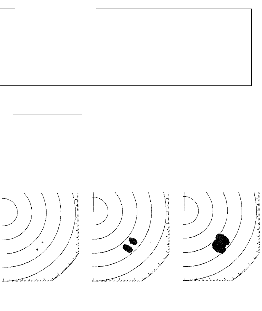
171
3.3.6 Adjusting the tuning
Please refer to "3.1.2 Tuning operation".
3.3.7 Adjusting the sensitivity
Please ensure that the sensitivity adjustment is made to an optimal level when
undertaking monitoring.
If the sensitivity is too low, hazardous objects, ships and other floating objects
may not be displayed.
If the sensitivity is too high, receiver noise at the PPI screen will increase and this
may impair monitoring.
(a) Turn the [Gain] control.
・When the control is turned in the counterclockwise direction, the sensitivity de-
creases and when the control is turned in the clockwise direction, the sensitivity
increases.
・In general, optimal adjustment of sensitivity is as follows.
The image size of the echo from the intended target is maximized.
It does not come into contact with echoes from other targets.
The image of the echo is
small as the sensitivity is
too low.
The sensitivity has been
adjusted to an optimal level.
Images overlap as the sen-
sitivity is too high.
Attention
172
3.3.8 Eradicating radar interference
Weak echo images from hazardous objects such as other vessels may also be
rejected when using the interference rejection function.
When observing radar beacons or SART signals, make sure that the interference
rejection function is disabled.
Radar interference refers to the phenomenon by which microwaves transmitted by a
third party radar is picked up directly by the ship's scanner unit and is displayed on the
PPI screen.
(a) Push the soft key
PROCESS
PROCESSPROCESS
PROCESS
.
(b) Push soft key 2 to select
IR
IRIR
IR
1
11
1
.
(c) If radar interference cannot be rejected using
IR
IRIR
IR
1
11
1
, push soft key 2 and
select
IR
IRIR
IR
2
22
2
.
When not undertaking interference rejection, push soft key 2 and select
IR
IRIR
IR
OFF
OFFOFF
OFF
.
(d) Push the
MENU
MENUMENU
MENU
key.
The soft key menu will return to the initial function display.
Interference rejection is enabled.
Prior to rejection of interference After rejection of interference
Example of radar interference
Attention
173
3.3.9 In the event of rain or snow
CAUTION
Refrain from setting the rain and snow clutter suppression function needlessly.
Doing so may suppress echoes from targets such as other vessels for hazardous
objects in addition to echoes from rain and snow thus impairing detection.
When using the rain and snow clutter suppression function, ensure that the
suppression setting is always at an optimal level.
When rain or snow falls, echo from the rain or snow (rain clutter) appears on the PPI
screen making it difficult to see images of echoes from vessels or other objects.
By using the [RAIN] control function or the "automatic rain and snow" function, rain
clutter may be suppressed facilitating monitoring of the target.
When the "automatic rain and snow" function is operating, it is not possible to use the
[RAIN] control function.
Manual rain and snow clutter suppression
Manual rain and snow clutter suppressionManual rain and snow clutter suppression
Manual rain and snow clutter suppression
(a) Turn the [RAIN] control.
As the control is turned to in the clockwise direction, the rain and snow clutter
suppression function becomes stronger.
Automatic rain and snow clutter suppressi
Automatic rain and snow clutter suppressiAutomatic rain and snow clutter suppressi
Automatic rain and snow clutter suppression
onon
on
(a) Push the soft key
PROCESS
PROCESSPROCESS
PROCESS
.
(b) Push the soft key 1 and select
A-RAIN
A-RAINA-RAIN
A-RAIN
.
Rain and snow clutter suppression is enabled depending on the condition of the image.
(c) Push the
MENU
MENUMENU
MENU
key.
The soft key menu will return to the initial function display.
Rain clutter has been suppressed (the
image of the echo from the target is
also suppressed).
Rain clutter is being shown as an
image