Japan Radio NTG337-XL0 User Station User Manual Manual
Japan Radio Co Ltd. User Station Manual
UserManual.wiki
>
Japan Radio
>
NTG337 XL0 User Manual
Manual
Navigation menu
Upload a User Manual
Namespaces
Wiki Guide
HTML
PDF
Info
Views
User Manual
Discussion / Help
Navigation

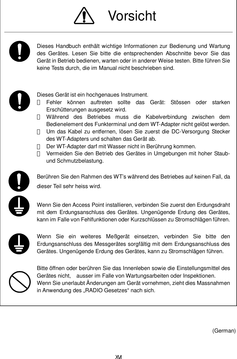
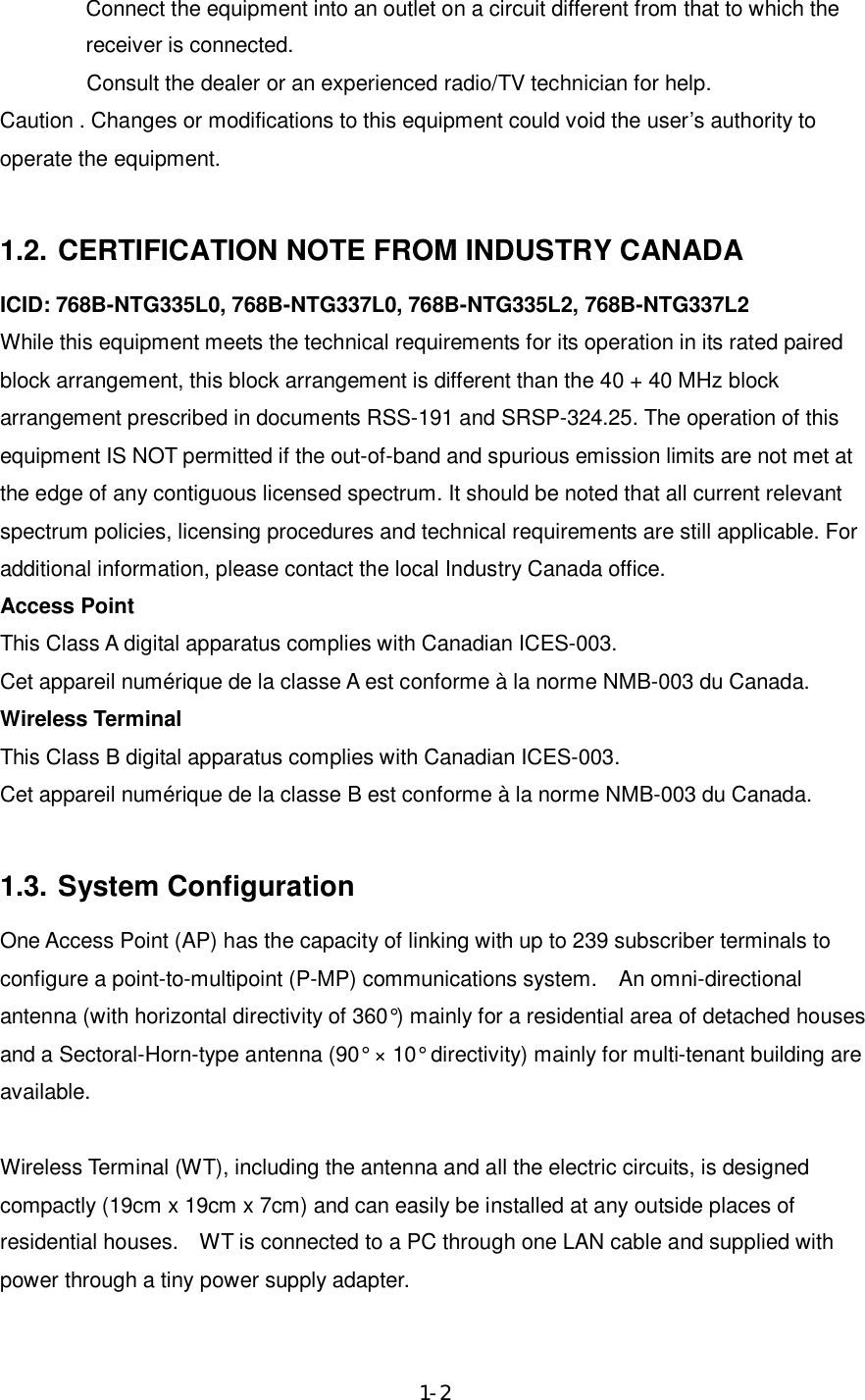
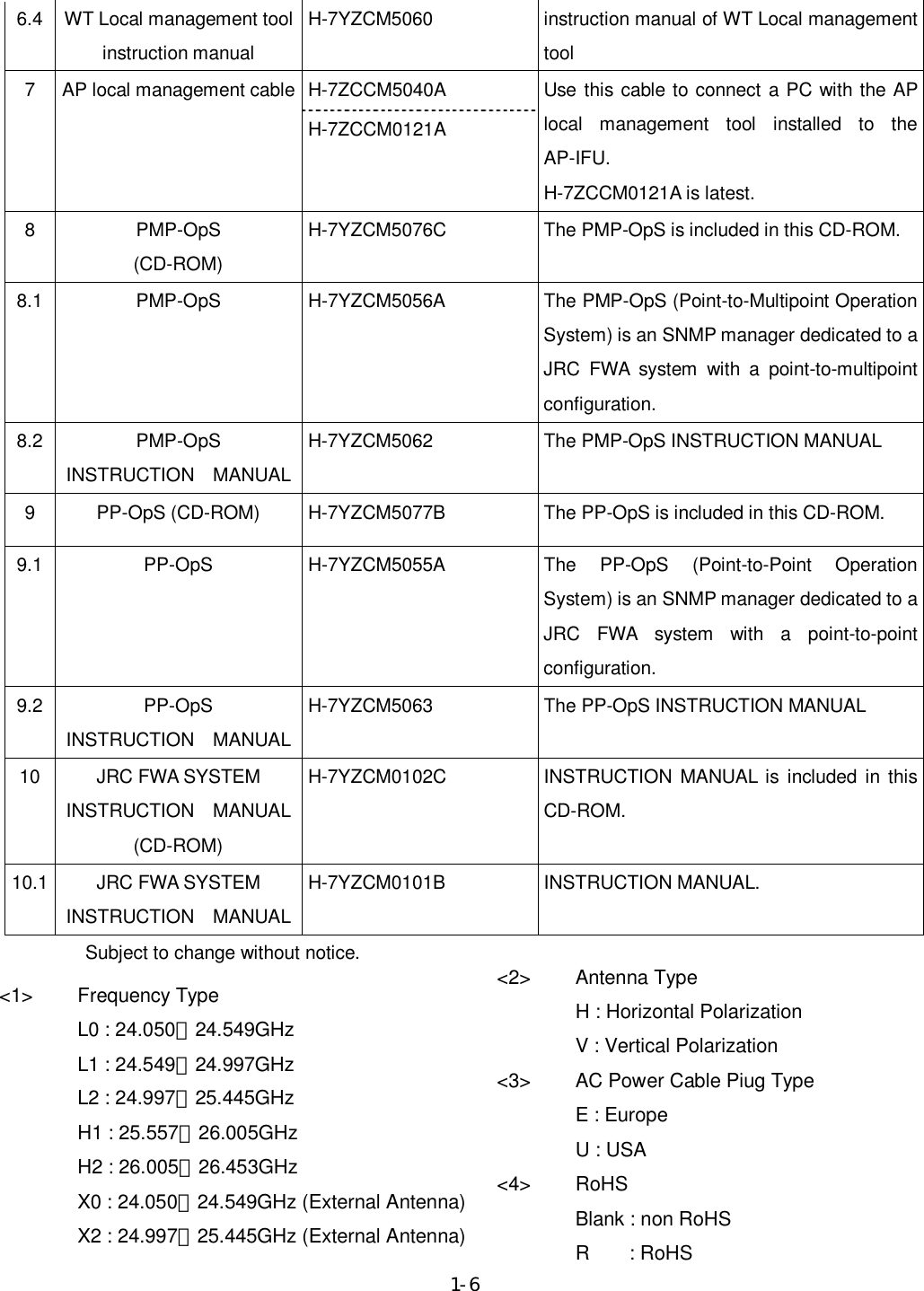
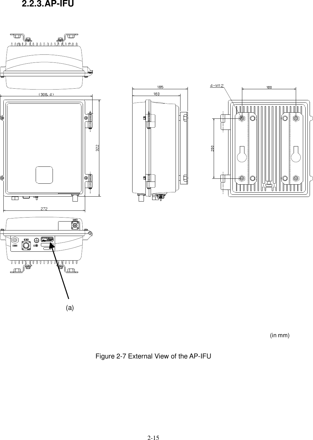
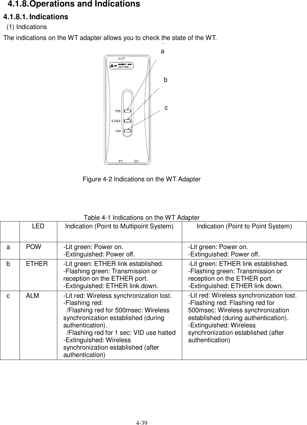
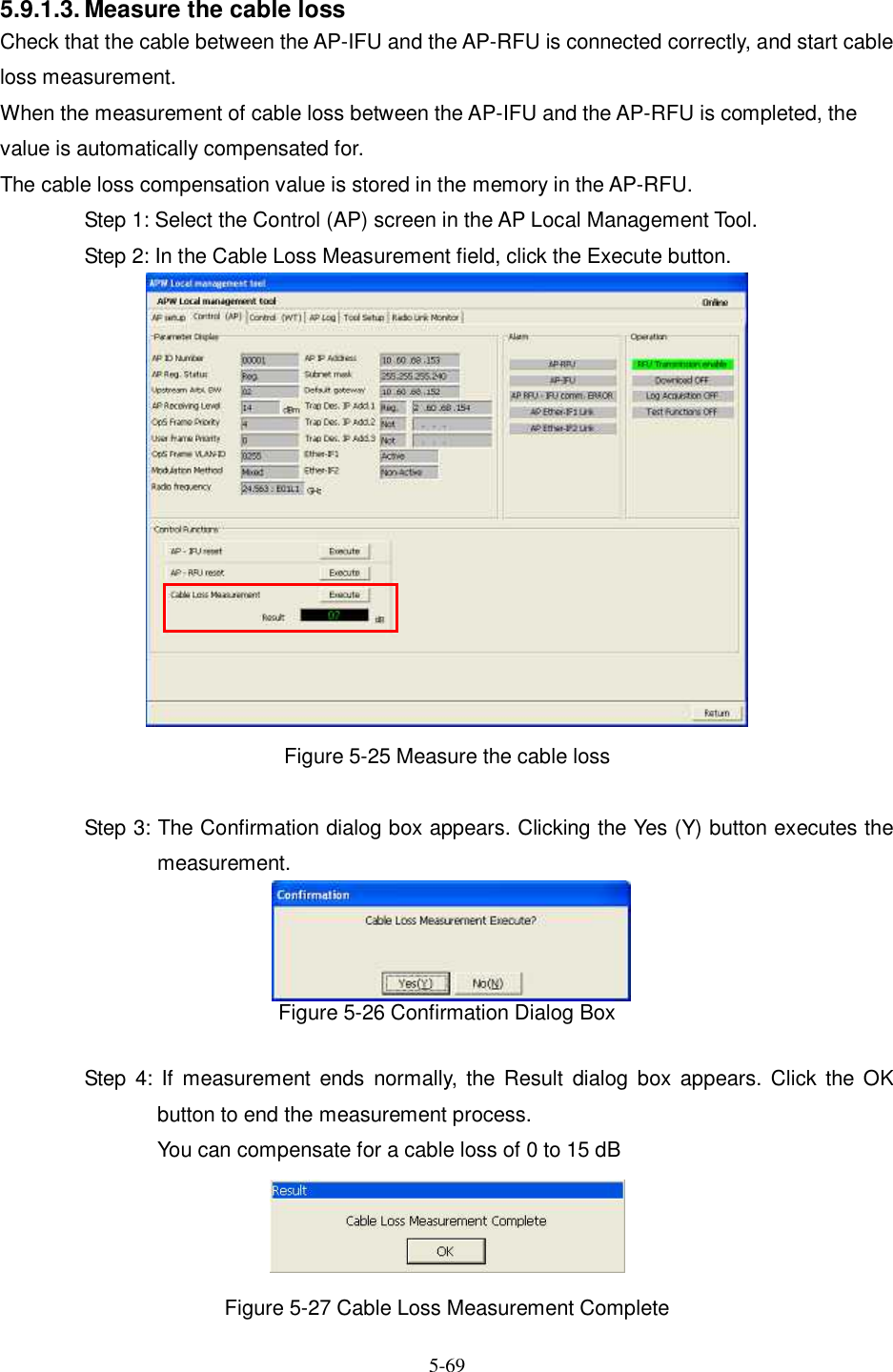
![2-7 2. Specifications 2.1. General Table 2-1 JRC FWA SYSTEM Specifications Point to Multipoint System Item AP WT Point to Point System Frequency Band EL0 EL1 EL2 EH1 EH2 [GHz] 24.050-24.549 24.549-24.997 24.997-25.445 25.557-26.005 26.005-26.453 Duplex/multiple access TDD/TDMA TDD Modulation system QPSK/16QAM Symbol rate 20M symbol/s Radio Transmission rate QPSK:40Mbps 16QAM:80Mbps QPSK:40Mbps 16QAM:80Mbps (Data throughput) (Max.23Mbps) (Max.46Mbps) (Max.16Mbps) (Max.32Mbps) Occupied bandwidth 26MHz (QPSK/16QAM) Channel spacing 28MHz Transmit output power QPSK:+14dBm QPSK (ATPC): -6 to +14dBm QPSK: -6 to +14dBm 16QAM (ATPC): -8.5 to +11.5dBm 16QAM: -8.5 to +11.5dBm Frequency Stability ±10ppm Transmitter spurious emission -30dB/MHz or less RF spectrum mask QPSK:ETSI Type A 16QAM:ETSI Type B Minimum receiving level (BER=10-6) After an error correction QPSK: -79dBm or less 16QAM: -69dBm or less Antenna type and gain Omni: 6.5dBi High-gain flat antenna: 31dBi (typ) 90°X10°Sectoral Horn:15.5dBi External Antenna: 35.7dBi(30cm) / 41.1dBi(60cm) / 44.6dBi(90cm) / 46.9dBi(120cm) Max number of WTs 239 WTs per AP - Interface 100BASE-TX 10BASE-T/100BASE-TX MAC processing VLAN (IEEE802.1Q) User data are distributed by using VLAN-TAG to each WT - MAC address filtering enable disable SNMP (agent) Remote operation is possible by OpS (option). SNMP V2, Private MIB, VLAN TAG (IEEE802.1q) AP setup/control WT setup/control Test Alarm log WT Operating Status List Remote downloading Bandwidth Table Parameter setup/Control (Master) Alarm Log (Master) Traffic information (Master) Network configuration (Master) Local management Local management is possible by Local management tool (option). AP: Serial interface(Exclusive cable use) WT: Ether interface Master/Slave: Ether interface Setup (AP,WT) Control (AP,WT) Radio link monitor (WT) Log (AP,WT) Tool Setup (AP,WT) Setup Control Radio link monitor Log Tool Setup (AP,WT)](https://usermanual.wiki/Japan-Radio/NTG337-XL0/User-Guide-1043348-Page-30.png)
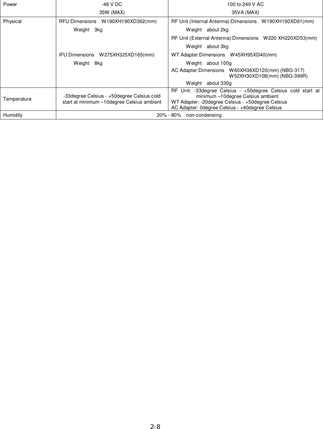

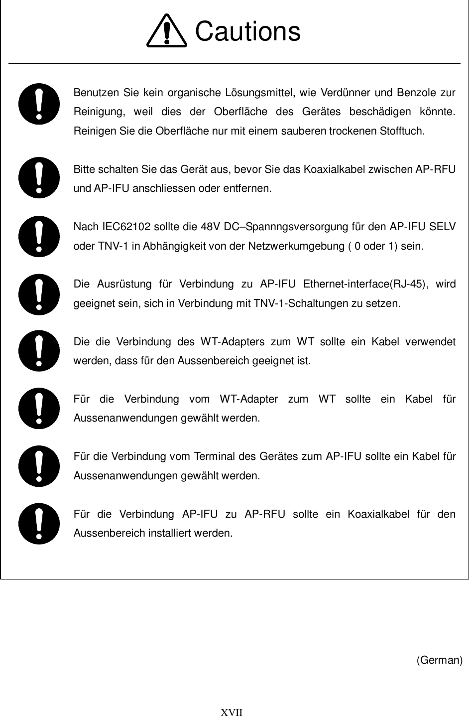
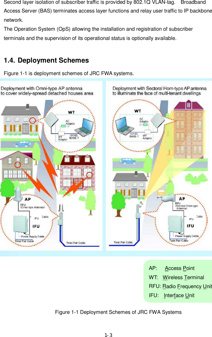
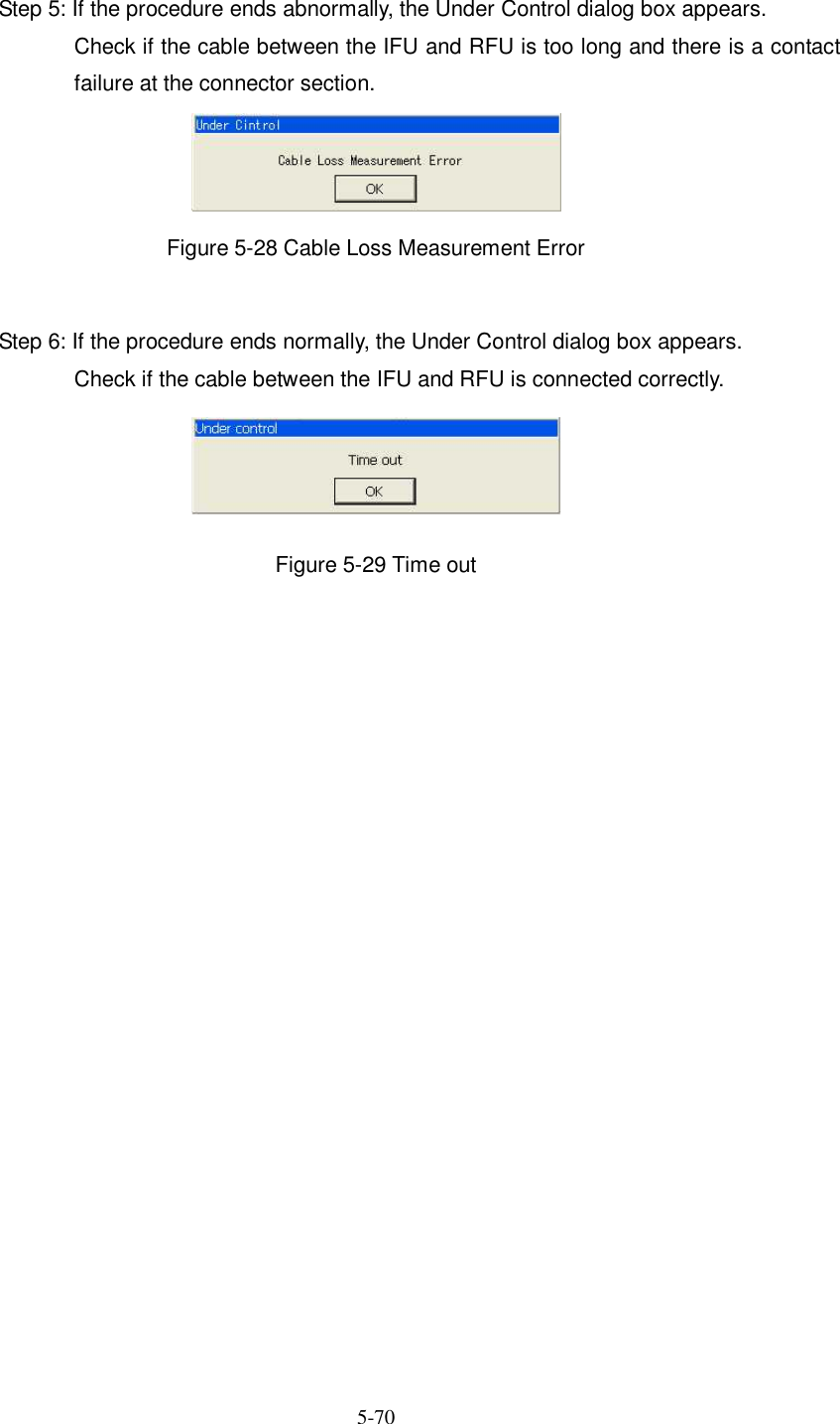
![3-26 The CPU in the IF section performs the AGC, the cable loss compensation, and the monitoring and control functionalities. Figure 3-1is a block diagram of the AP-RFU. to IFUAP-RFUWGBPFRFSWLNASW2.4GHzSynth26G:×5×n×2DOWN_CONVTRSEL(RF)PA×2UP_CONVFREQ_CNTIF部HYBASKMODEMTempCNT D/AD/AAGC×21282.5MHzATPCAGC213.75MHzMAX_HOLD/AVERAGING A/DTRCNTVariable[20dB]TempCNTRFU¦IFUContTemp SensVAR_ATT[30dB]CABLELOSSDC+16VLOGAMPTMGGenTHCNTObstacleinformationTRSEL(RF)FREQ_CNT[DATLCLK/LE]427.5MHzSAW_BPFIF_Freq1710MHzSAW_BPFHornAntenna(V/H)orOmniAntenna(V/H)×3BPFSAWBPFBPFBPFLOGAMPSAW_BPFAGC2RX_LVLCNTAUTO ON/OFFAGC2RFU-IFRFU_PSSerge protectionCoaxalCABLEHYBCOMP Figure 3-1 AP-RFU Block Diagram 3.1.5. Operations and Indications The AP-RFU does not have any operation or indication panels. 3.1.5.1. Indications The AP-RFU does not have any LEDs or other status indicators. 3.1.5.2. Switches The AP-RFU does not have any switches.](https://usermanual.wiki/Japan-Radio/NTG337-XL0/User-Guide-1043348-Page-49.png)
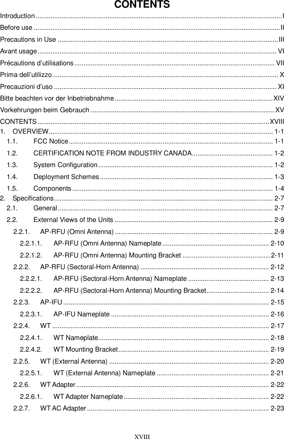
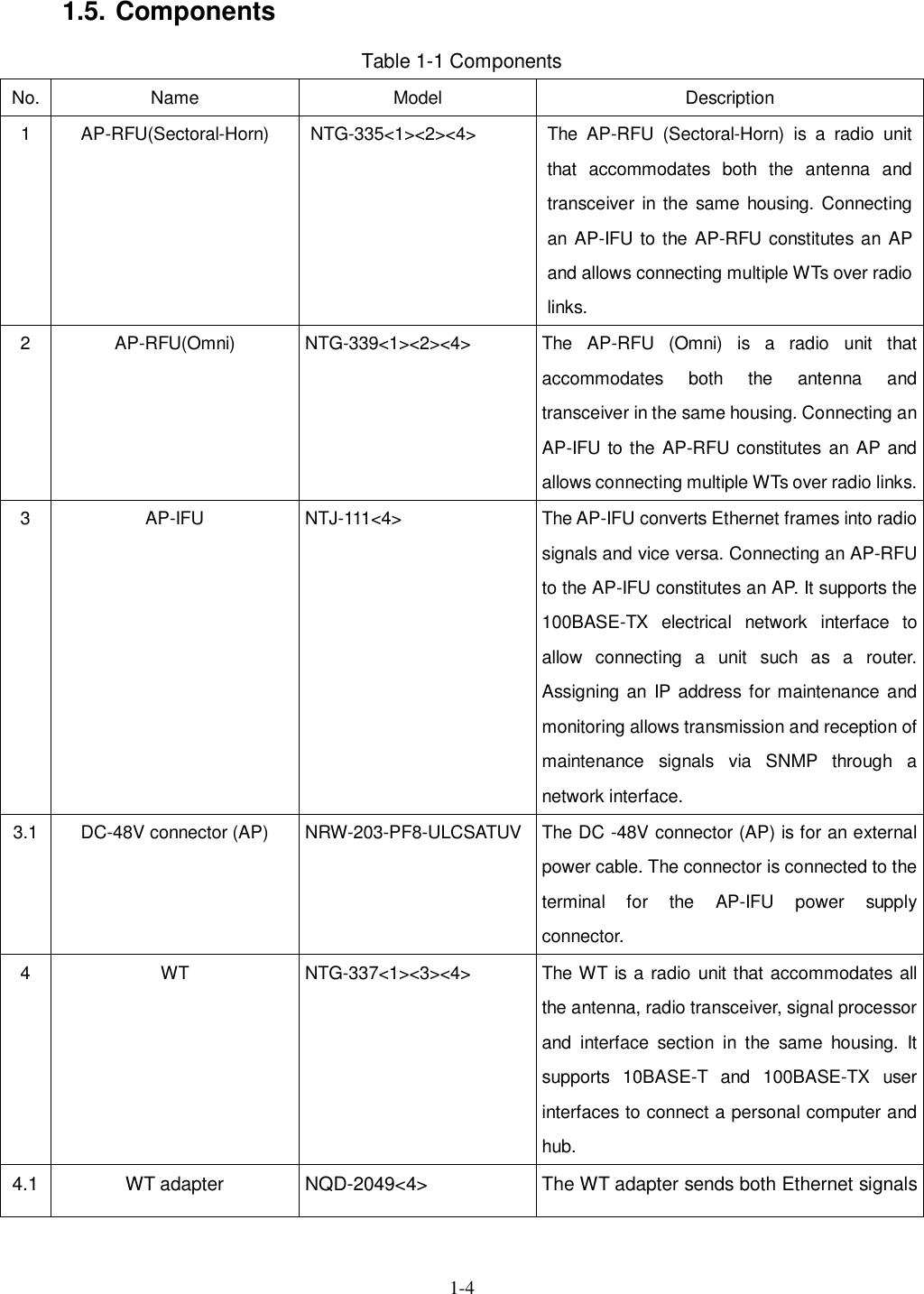
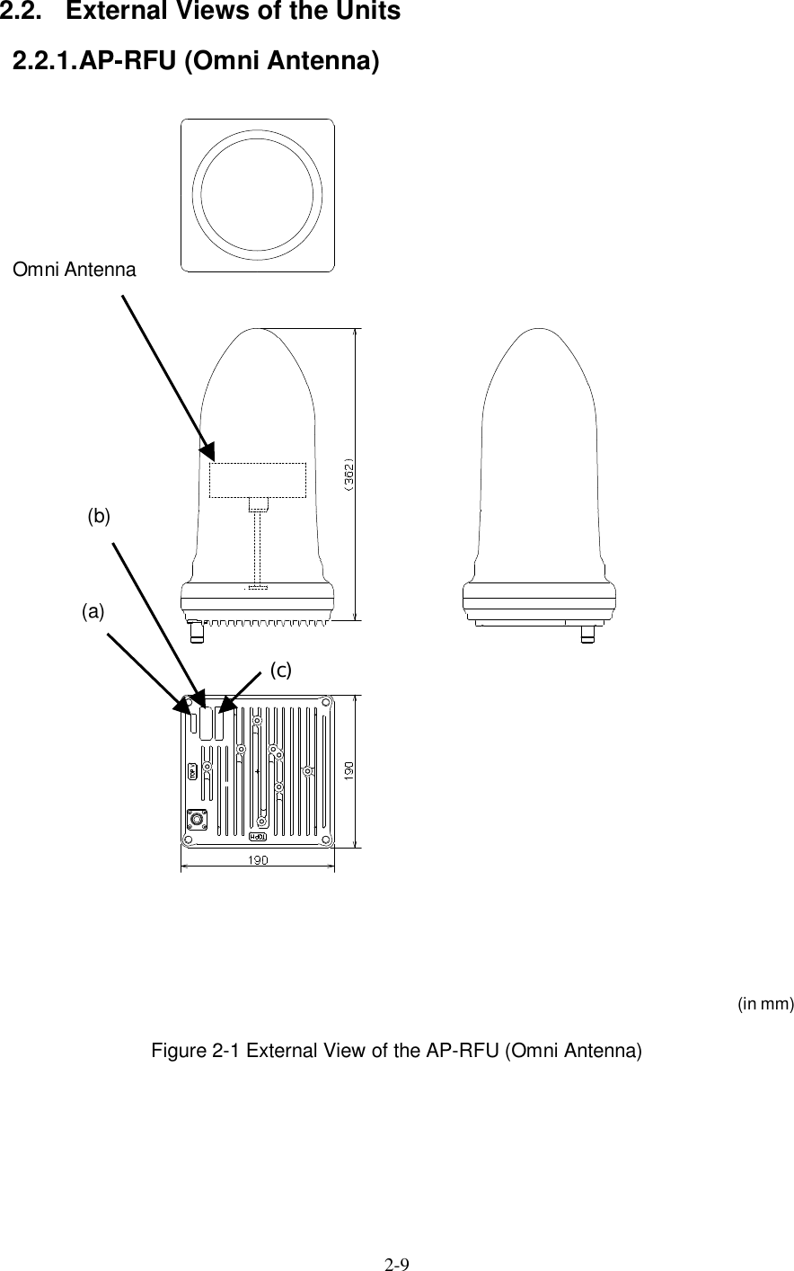
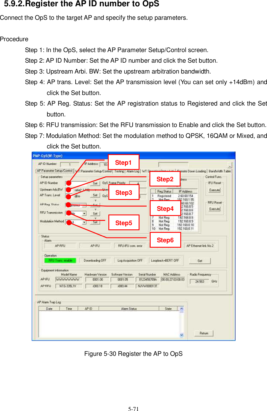
![3-29 +5VRegulator0/90HYB ×20/0 BALUNBLC_BPF213.75MHzLC_LPF +5.0 LC _B PF+5.0LC_LPFdigitalATT[15dB]UNBBAL-3.3V+3.3_MOD +3.3_ DE M+5V+16V+16Vto RFURegulatorRegulator0/00/90ASKMODEMInterface partPHY_RST(FROM_AP-ASIC)L2SW_RST(FROM_AP-ASIC)TRANSLAYER2SWRJ-45RJ-45TRANSPHYTRANS TRANS25MHzRS-232Cdriver/receiver4pinMOJUR AMACTDDAP-ASICDigital partU-CPU15.625MHzResetIC TMPSENS20MHzLVL CNT_T/R+16V(RFU)+3.3V(for AP/MODEM-ASIC,IF)+2.5V(for AP-ASIC)+1.8V(for U-CPU,D-CPU,L2SW)+1.5V(for MODEM-ASIC)+5V(for ANALOG ⇒3.3V)CABLELOSSATT(ATT)AP-IFU+2.5V+3.3V+1.8V+3.3VMODDEMMODEMASICS-CPURTCFROM64MserialEEPROM32×8SDRAM8M×16D-CPUFROM16MSDRAM8M×16FROM16MSDRAM8M×1627.83MH zTXRXD-FIFOD-FIFOEDC2.5MHzS_RST[FROM_AP-ASIC] D_RST[FROM_AP-ASIC] U_RST[FROM_AP-ASIC]MODEM-ASIC_RST(FROM_S-CPU)+1.8V+5VRegulator+3.3_ASICANALOG+1.5VTDD_SELECTIFU-MAC(to PC)DC-48VPowsupplyconn.Powersupplyconnector100BASE-TXPowsupplyconn.IF partSWMOD_I/Q(BAL)DEM_I/Q(UNBAL)to RFUSerge protectionSerge protectionSerge protectionIFU-PSCoaxalCABLE Figure 3-4 AP-IFU Block Diagram](https://usermanual.wiki/Japan-Radio/NTG337-XL0/User-Guide-1043348-Page-52.png)
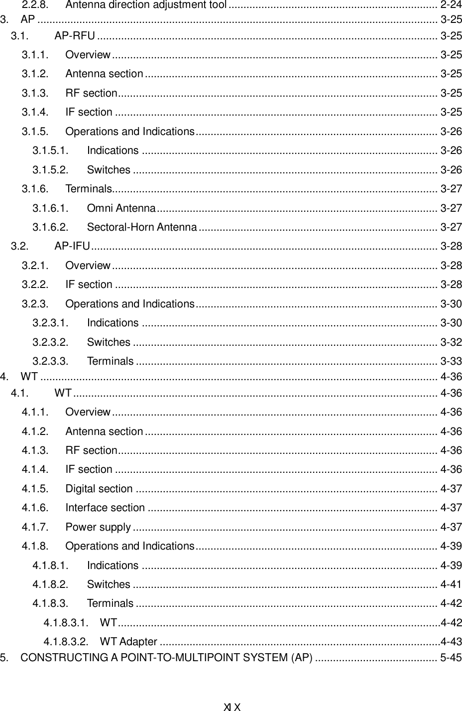
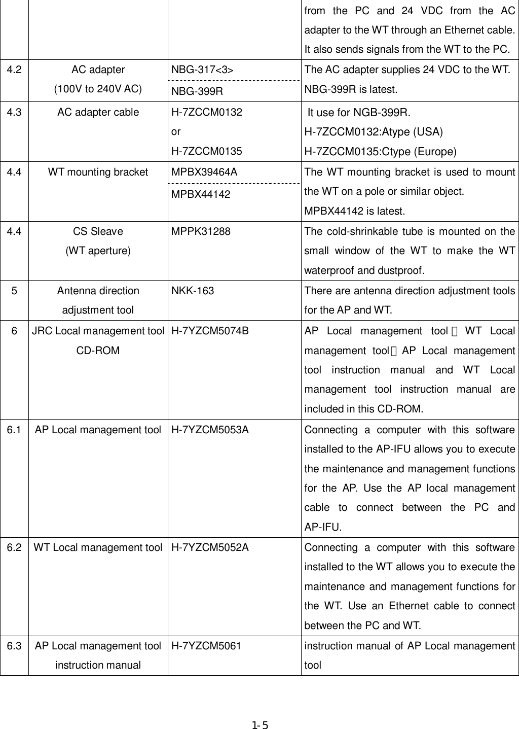
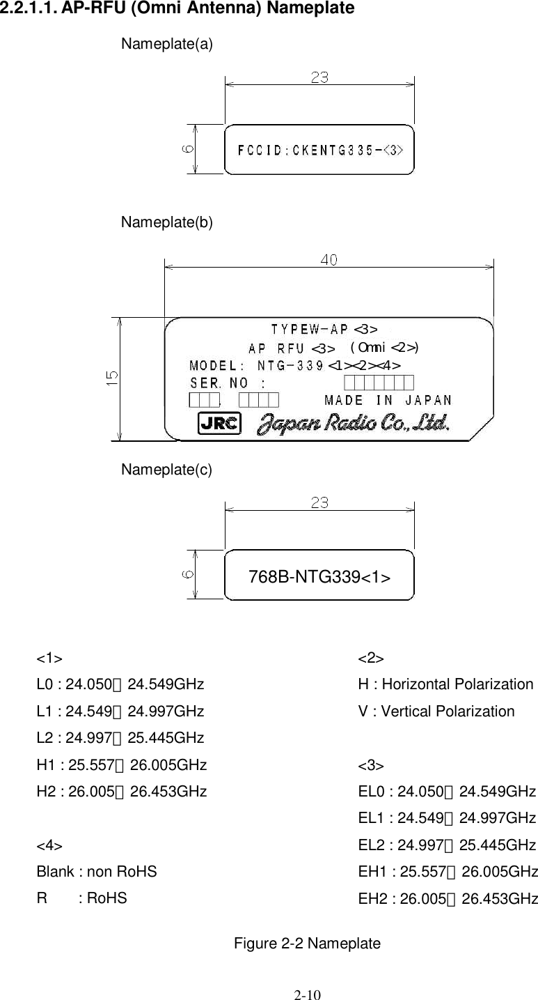
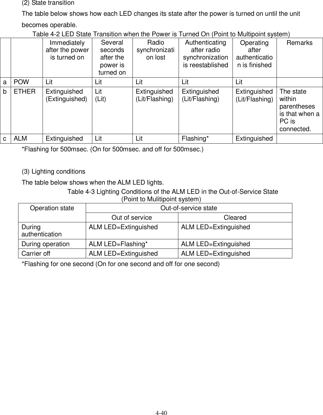
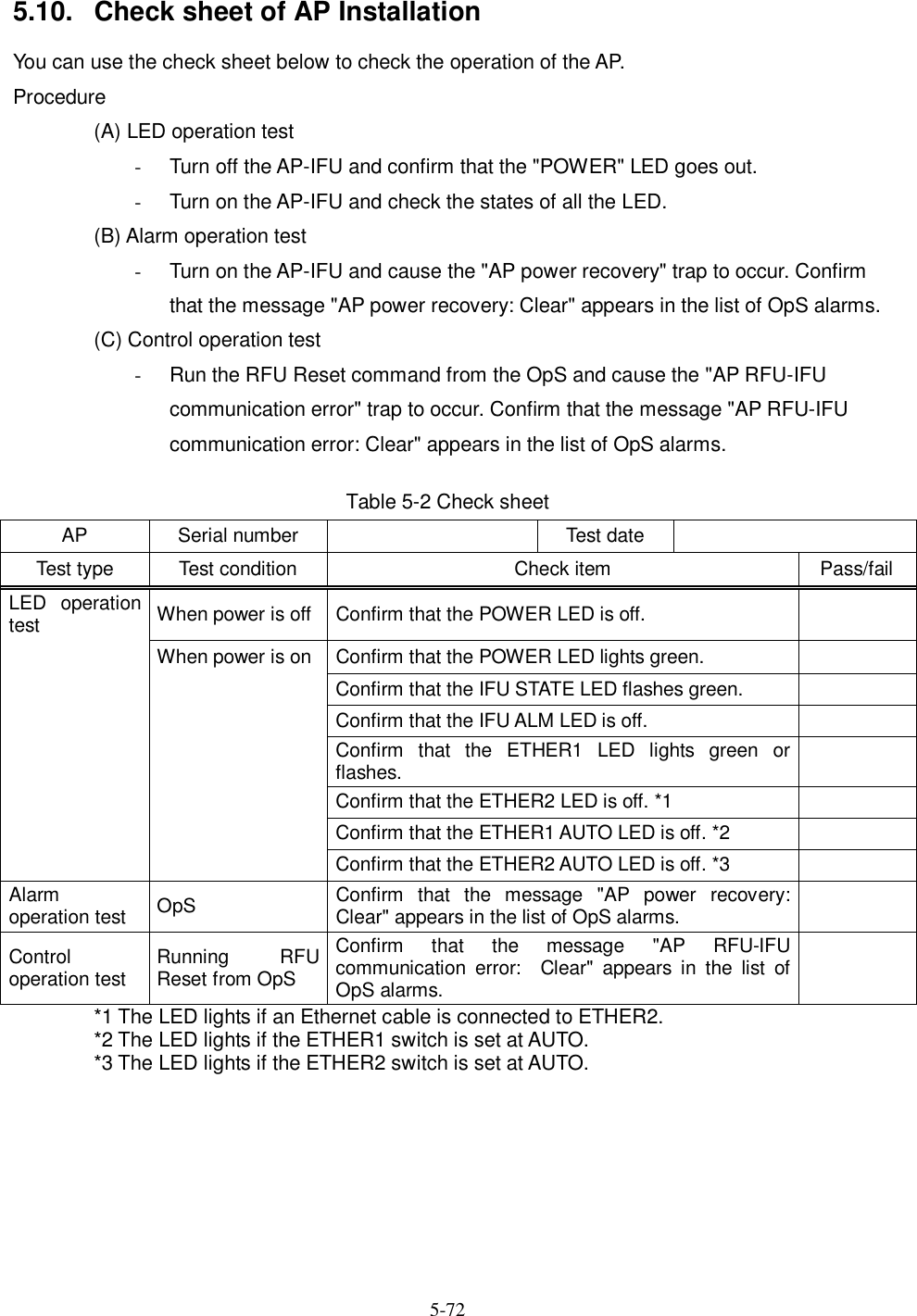
![4-38 Figure 4-1 is a block diagram of the WT. Interface partTransSerge protectionPHYRJ45RS-232DRV/REC4P_MJLED DRVMJMJMOD_I/Q(BAL)DEM_I/Q(UNB)Power supply part(digital)DC/DCCONV+3.3V_D(DIGITAL)+3.3V_A(ANALOG)+1.5V(for ASIC)AGC(Analog)TRSEL(RF)X'TALMAC TDDMODDEMCPUASICATPC(Analog)DC+24VAGC(Digital)ATPC(Digital)TRSEL(IF)to IF partD/AConvD/AConvPLL20MHz/80MHzSignal processing partFRASHROMTEMPSENSPONRST EEPROM SDRAMOFFSET_CNTFREQ_CNT(RF) AntennaWGBPFRFSWLNASW2.4GHzSynth26G:×5×n×2DOWN_CONVTRSEL(RF)PA×2UP_CONVFREQ_CNTto Signal processing part0/900/90HYB×20/0213.75MHzSW TRSEL(IF)DEM_I/QAGC(Analog)UNBBALSAW_BPFDEM_ICAGC(Digital)0/0WT-IFMOD_ICATPC(Analog)MOD_I/Q×3 HYB427.5MHz 1282.5MHzIF_Freq1710MHzTRSEL(RF)FREQ_CNT[CLK/DAT/LE]BALUNBSAW_BPFATPC(Digital)HYBDielectric_BPFIRFIF_Freq1710MHzSAW_BPFLC_BPFWT-MACWT_PSWT Figure 4-1 WT Block Diagram](https://usermanual.wiki/Japan-Radio/NTG337-XL0/User-Guide-1043348-Page-61.png)
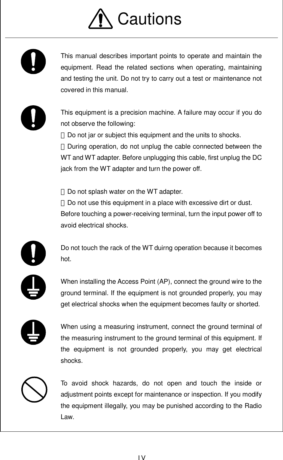
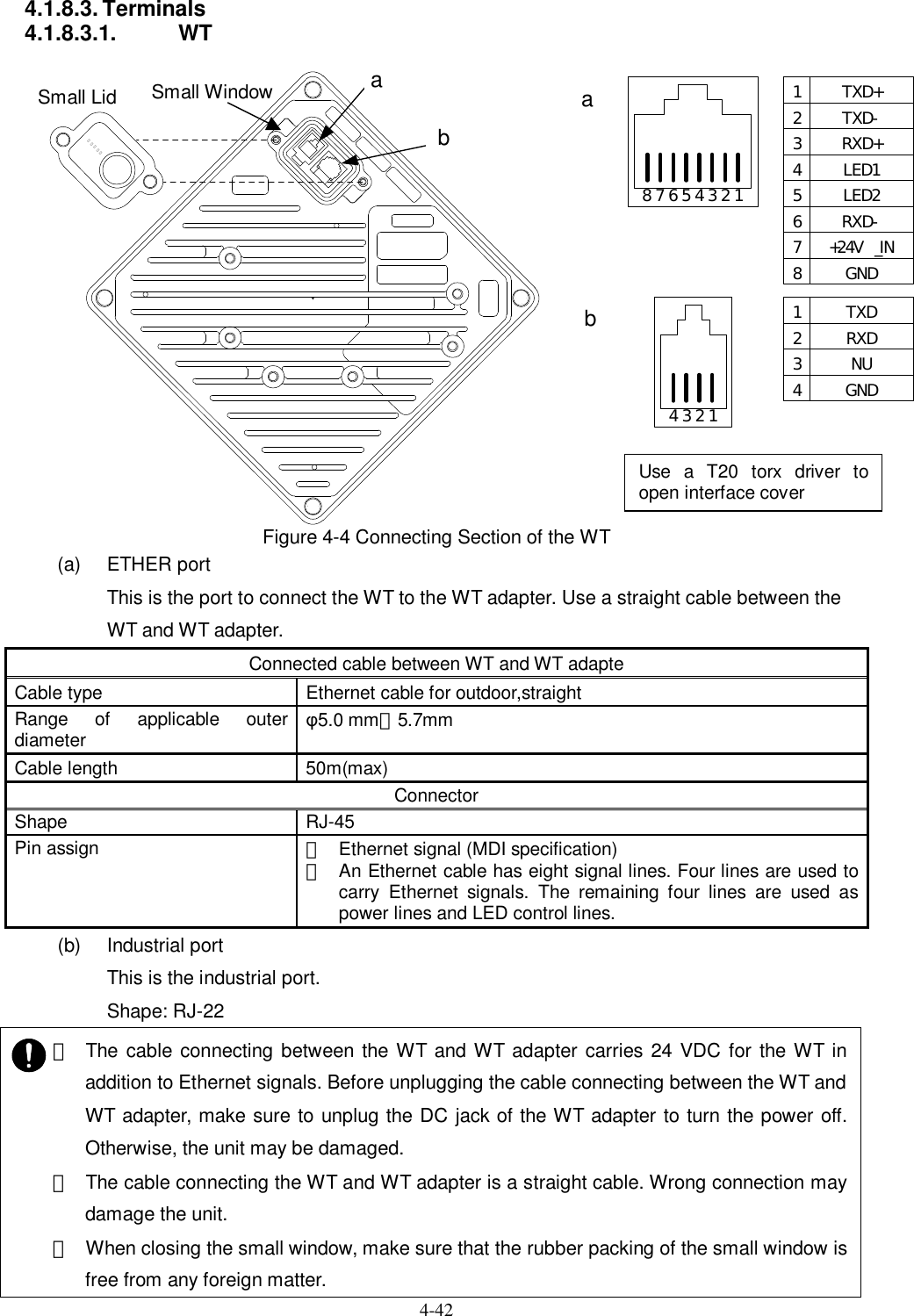
![4-41 4.1.8.2. Switches Figure 4-3 Switches on the WT Adapter (a) [TEST SW] switch This is the switch to check for any disconnection on the Ethernet cable connecting the WT and WT adapter. The connection of the ETHER signal line (4) in the Ethernet cable (8) can be confirmed. If you turn on this switch, the Ethernet signal is looped back to the WT and not output to the PC port. How to check for a disconnection: • connected to cable between WT and WT adapter, and turns on the power supply with the AC adapter. • Unplug the cable from the PC port of the WT adapter. • Make sure that the ETHER LED lights. • Hold down the TEST SW switch. • (The Ethernet signal from the WT is looped backed to the WT via the WT adapter.) • The connection is normal if the ETHER LED lights green. • The four Ethernet signal lines have a disconnection or wrong wiring if the ETHER LED remains extinguished. ・ The TEST SW cannot identify a wrong connection for the straight/cross cable. When connecting a connector, make the correct connection for the straight or cross cable. If you turn on this switch by mistake, the Ethernet signal is looped back to the WT and not output to the PC port. Test SW ETHER LED PC port](https://usermanual.wiki/Japan-Radio/NTG337-XL0/User-Guide-1043348-Page-64.png)
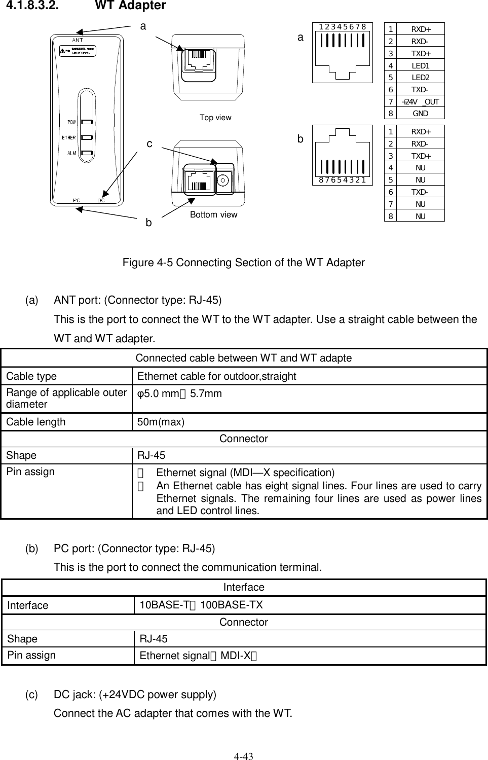
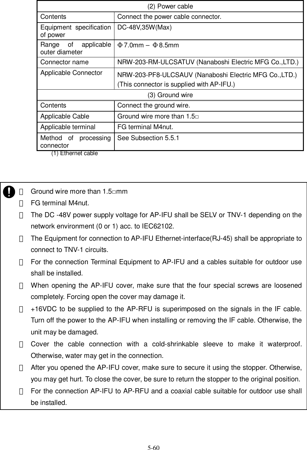
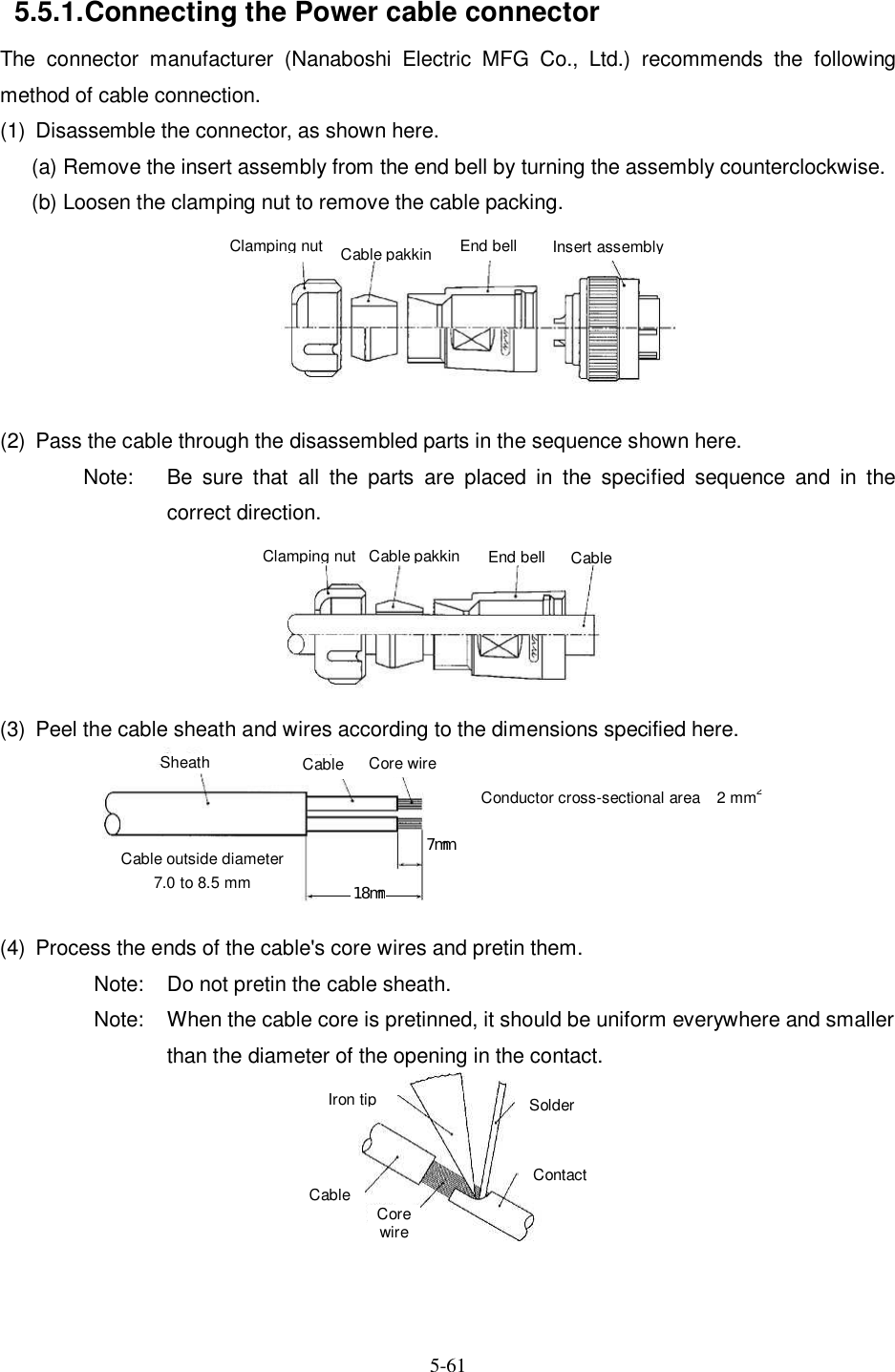
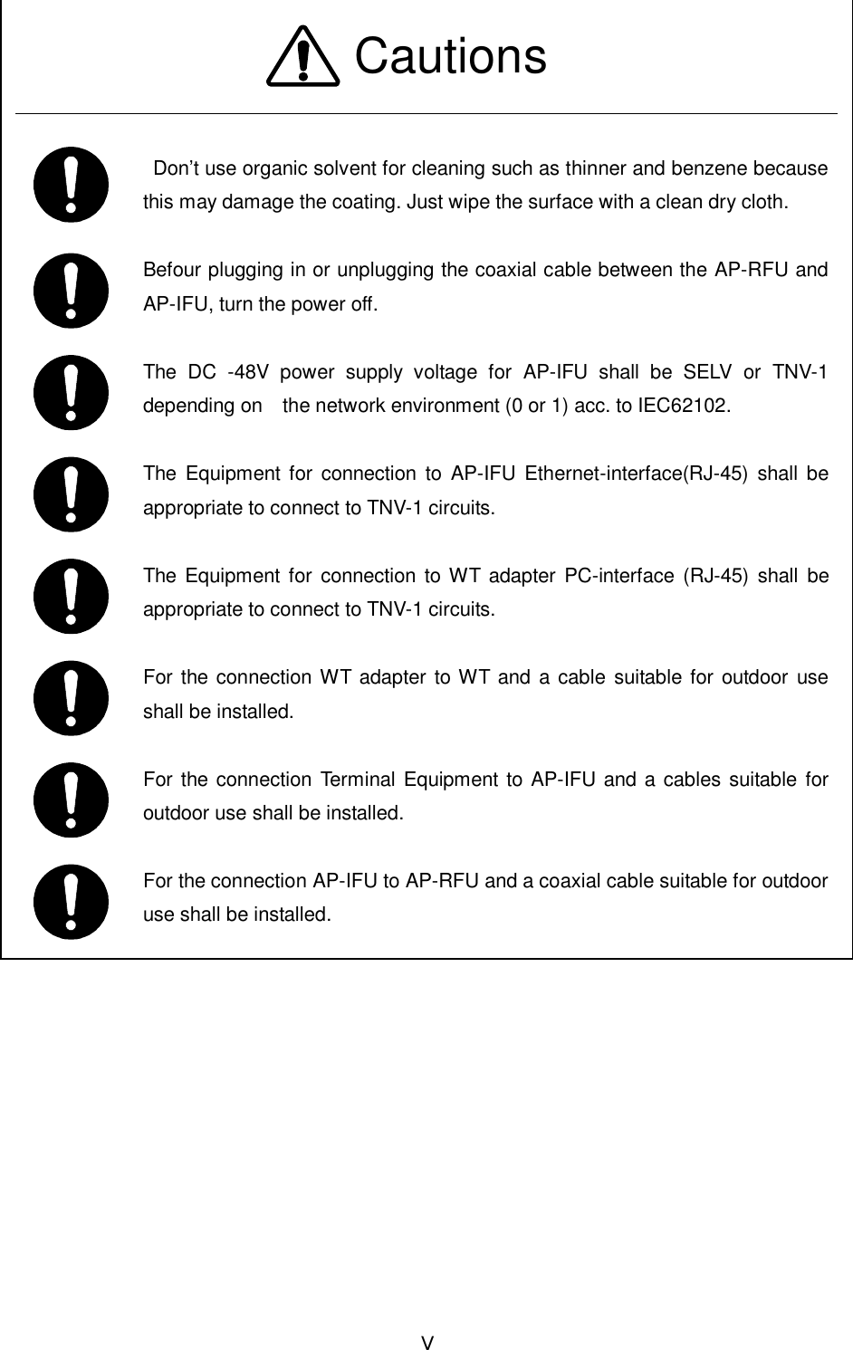
![5-62 (5) Soldering (a) Insert the pretinned core wires into the contact's solder pot. (b) Using a soldering iron, heat the contact and the core wires. (c) Let solder flow into the gap between the contact and the core wires until the gap is filled. (6) Assemble the connector. (a) Clamp the insert assembly and tighten the end bell with the specified torque. (b) Push the cable packing into the end bell, clamp the end bell, and tighten the clamping nut with the specified torque. (c) Move the cable back and forth until it moves easily (as shown). Once again, tighten the parts with the specified torque. Soldering iron wattage [W] Conductor cross-sectional area [mm2] Iron tip temperature [℃] 30 2 350 to 370 Where to tighten Shell size: 20 End bell 1.0 to 1.5 Clamping nut 1.5 to 2.0 [Unit: N-m] Clamping nut Cable pakkin End bell Insert assembly](https://usermanual.wiki/Japan-Radio/NTG337-XL0/User-Guide-1043348-Page-85.png)
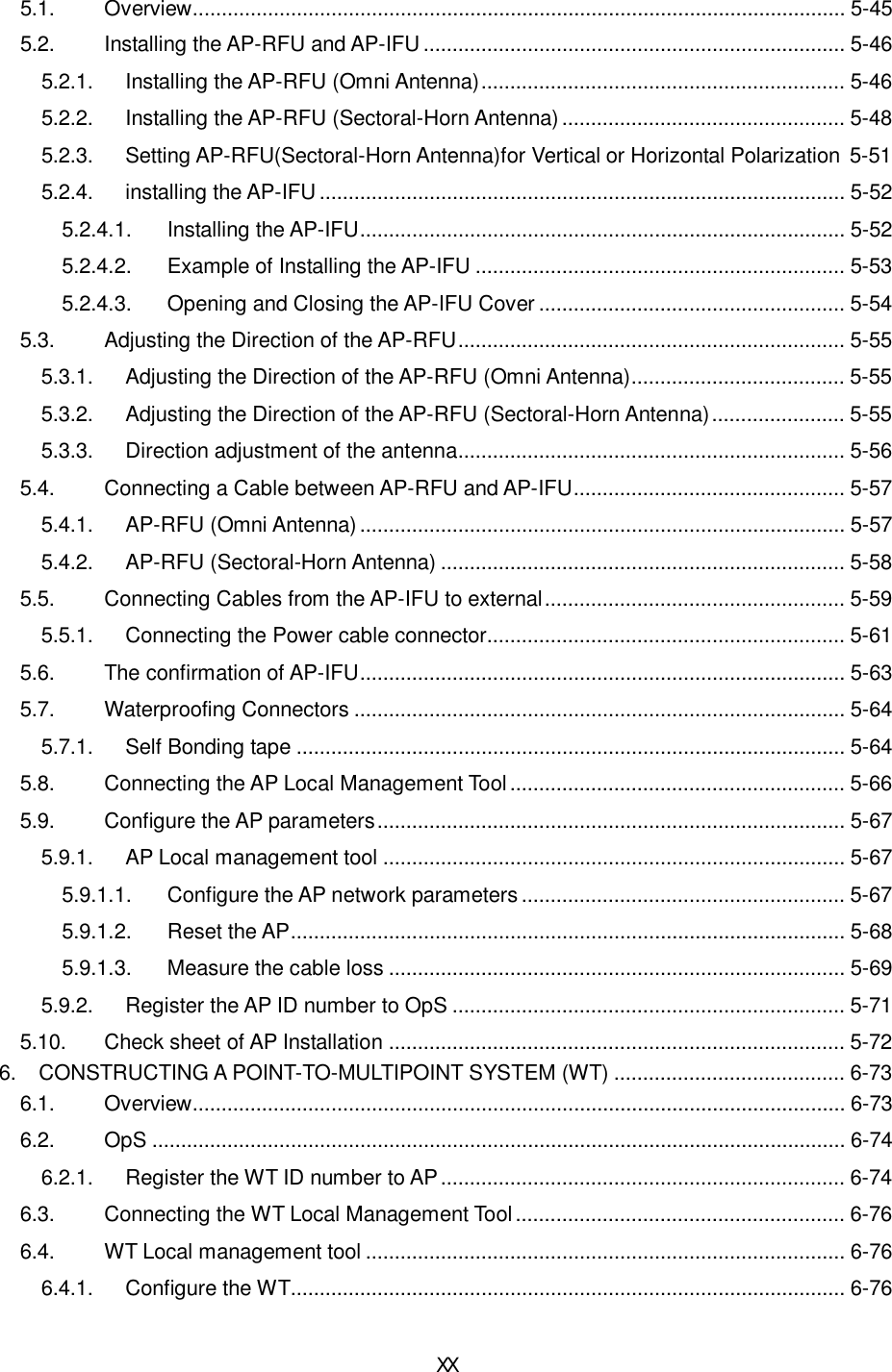
![6-74 6.2. OpS 6.2.1. Register the WT ID number to AP Connect the OpS to the target AP and register a WT. Step 1: In the OpS, select the WT Parameter Setup/Control tab. Step 2: Select the WT from "Select WT ID number." Step 3: Specify the setup parameters. - VLAN-TAG Cont: Set the VLAN-TAG Cont to Transparent. - Authen Param: Set the authentication parameter. - Serial number: Set the serial number and click the Set button. - WT Reg. Status: Set the WT registration status to Registered and click the Set button. - Modulation: Set the modulation to QPSK, 16QAM, or Adaptive and click the Set button. - Interface Class: Set the interface class to AUTO or 10BASE and click the Set button. - RFU Transmission: Set the RFU Transmission to Enable and click the Execute button. The following dialog box appears since a value is already set for "RFU Transmission." Click the OK button. - UP Stream Bandwidth table [Maximum Limit / Minimum Guarantee] - Down Stream Bandwidth table [Maximum Limit / Minimum Guarantee] Clicking the Set button displays a dialog box. Place checkmarks in the checkboxes and click the Set button. Step 4: Set the VLAN-ID. - VLAN-ID: Set the VLAN-ID and click the Register button. - Since the VLAN-ID that has been set appears on the screen, select it. - VLAN-ID Registration status: Set the VLAN-ID registration status to Registered. - Service status [ out of service / In service ] : Set the Service status to In service](https://usermanual.wiki/Japan-Radio/NTG337-XL0/User-Guide-1043348-Page-97.png)
![6-75 Figure 6-1 Register the WT ID number to AP Step1 Step2 Step3 Step4 Set Bandwidth table Select [Parameter setup/control] tab Select the WT ID number set parameters Set VLAN-ID](https://usermanual.wiki/Japan-Radio/NTG337-XL0/User-Guide-1043348-Page-98.png)


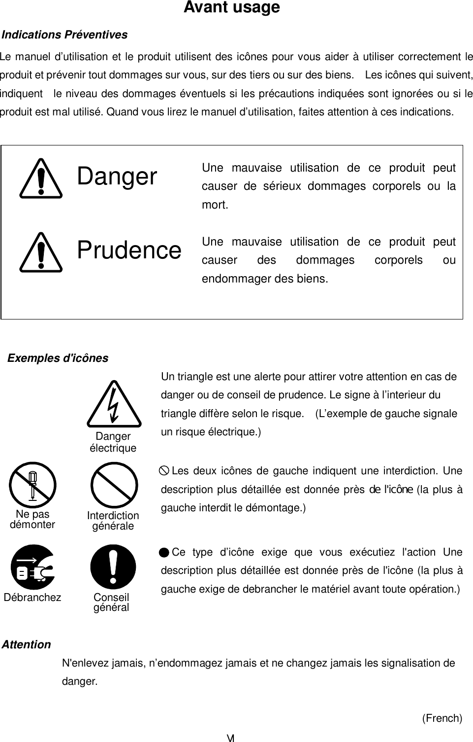
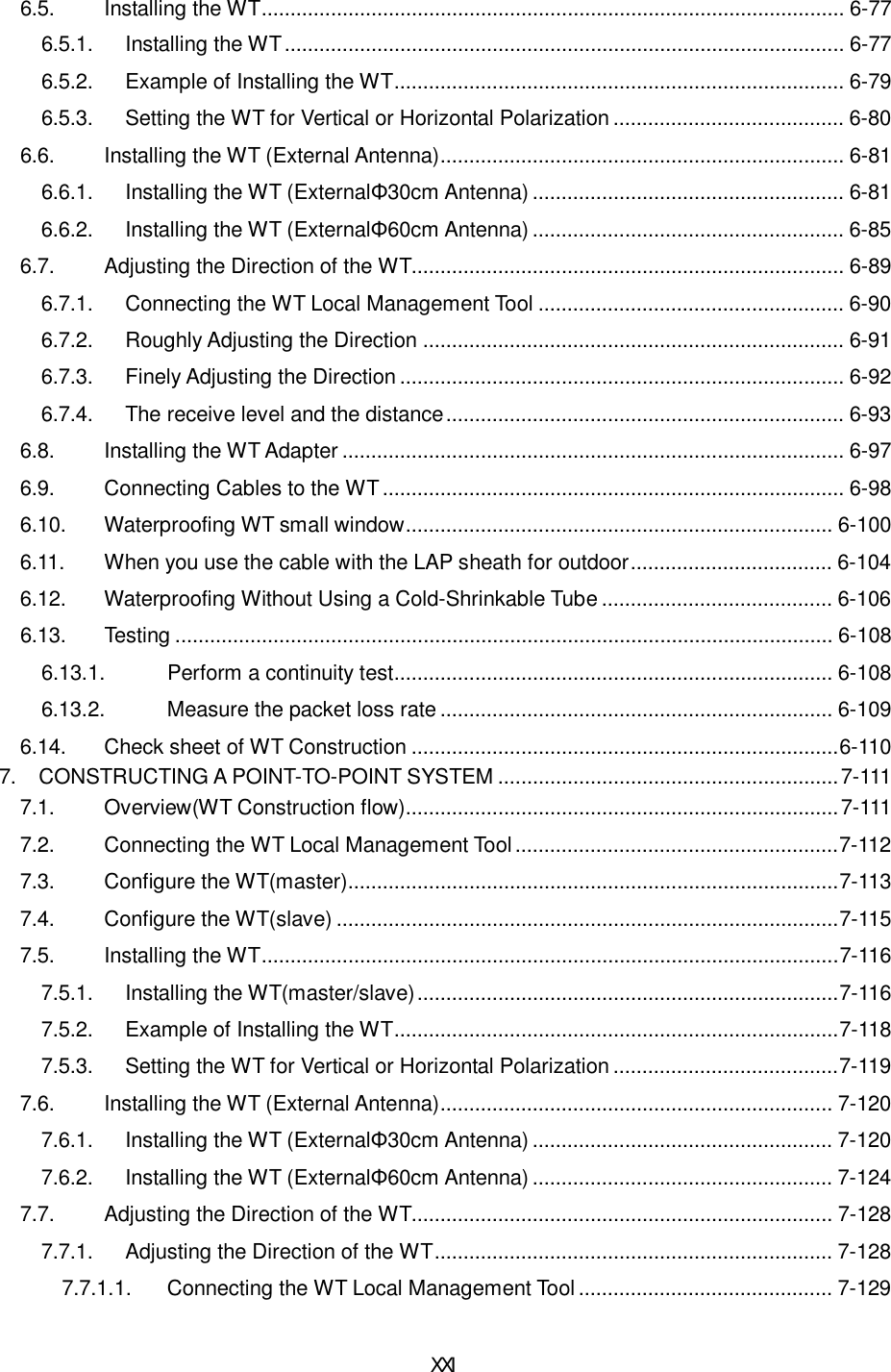
![6-93 6.7.4. The receive level and the distance For the receiving AP-RFU (Sectoral-Horn Antenna) in a point-to-multipoint system, the receiving level at clear sky and the distance are related as shown in Figure 6-38. Figure 6-38 Receiving Level and Distance (Sectoral QPSK) -90-80-70-60-50-40-30-20-1001 10 100 1000 10000Distance[m]Receiving Level [dBm]Maximum Receiving Level WT Receiving Level AP Receiving Level Minimum Receiving Level Transmission level (QPSK) 14 [dBm] Free space loss Lp[dB]Frequency 26 [GHz]Antenna gain[TX+RX]TX Sectoral Antenna Gain:15.5dBiTYPRX WT Antenna Gain:31dBiTYP46.5 [dBi] λπdLp 4log20 Hzfmcmλ](https://usermanual.wiki/Japan-Radio/NTG337-XL0/User-Guide-1043348-Page-116.png)
![6-94 Figure 6-39 Receiving Level and Distance (Sectroral 16QAM) -90-80-70-60-50-40-30-20-1001 10 100 1000 10000Distance[m]Receiving Level [dBm]Transmission level (QPSK) 11.5 [dBm] Free space loss Lp[dB]Frequency 26 [GHz]Antenna gain[TX+RX]TX Sectoral Antenna Gain:15.5dBiTYPRX WT Antenna Gain:31dBiTYP46.5 [dBi] λπdLp 4log20 HzfmcmλWT Receiving Level Maximum Receiving Level AP Receiving Level Minimum Receiving Level (16QAM)](https://usermanual.wiki/Japan-Radio/NTG337-XL0/User-Guide-1043348-Page-117.png)
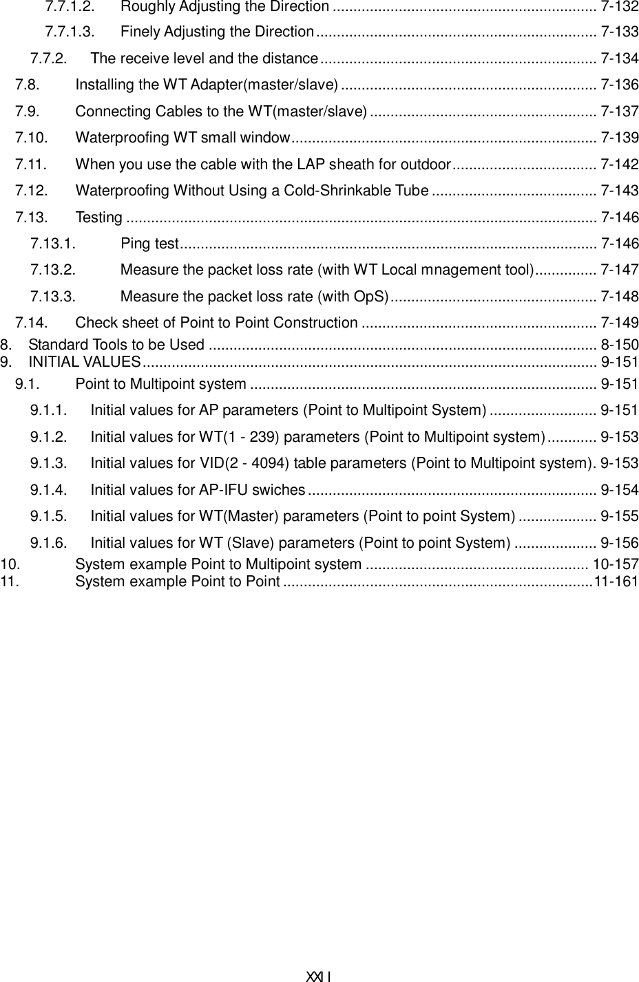
![6-95 Figure 6-40 Receiving Level and Distance (Omni QPSK) -90-80-70-60-50-40-30-20-1001 10 100 1000 10000Distance[m]Receiving Level [dBm]Transmission level (QPSK) 14 [dBm] Free space loss Lp[dB]Frequency 26 [GHz]Antenna gain[TX+RX]TX Sectoral Antenna Gain:6.5dBiTYPRX WT Antenna Gain:31dBiTYP37.5 [dBi] λπdLp 4log20 HzfmcmλMaximum Receiving Level AP Receiving Level Minimum Receiving Level WT Receiving Level](https://usermanual.wiki/Japan-Radio/NTG337-XL0/User-Guide-1043348-Page-118.png)
![6-96 Figure 6-41 Receiving Level and Distance (Omni 16QAM) -90-80-70-60-50-40-30-20-1001 10 100 1000 10000Distance[m]Receiving Level [dBm]Transmission level (QPSK) 11.5 [dBm] Free space loss Lp[dB]Frequency 26 [GHz]Antenna gain[TX+RX]TX Sectoral Antenna Gain:6.5dBiTYPRX WT Antenna Gain:31dBiTYP37.5 [dBi] λπdLp 4log20 Hzfmcmλ(16QAM) WT Receiving Level Maximum Receiving Level AP Receiving Level Minimum Receiving Level](https://usermanual.wiki/Japan-Radio/NTG337-XL0/User-Guide-1043348-Page-119.png)


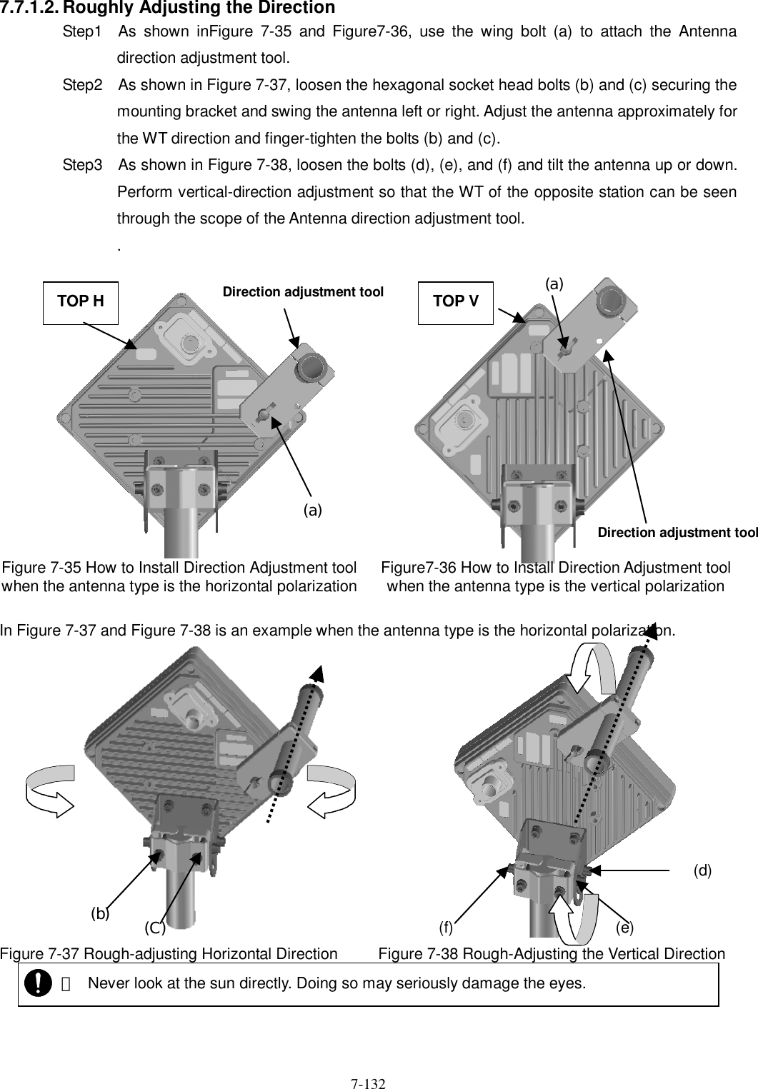
![7-131 (4) Method of adjustment for near-distance installation If circuit design calls for a receive level of -35 dBm or higher, use the following procedure: - Start the WT Local Management Tool and select P-P mode. - On the Master Setup screen in the master station in P-P mode, change "Trans.Level" from 14[dBm] to -6[dBm]. After the change, click the SETUP button. The procedure is shown in Figure 7-33. Figure 7-33 Setting "Trans.Level" for the WT (Master) - On the Slave Setup screen in the slave station in P-P mode, change "Trans.Level" from 14[dBm] to -6[dBm]. After the change, click the SETUP button. The procedure is shown in Figure 7-34. Figure 7-34 Setting "Trans.Level" for the WT (Slave) OFF](https://usermanual.wiki/Japan-Radio/NTG337-XL0/User-Guide-1043348-Page-154.png)
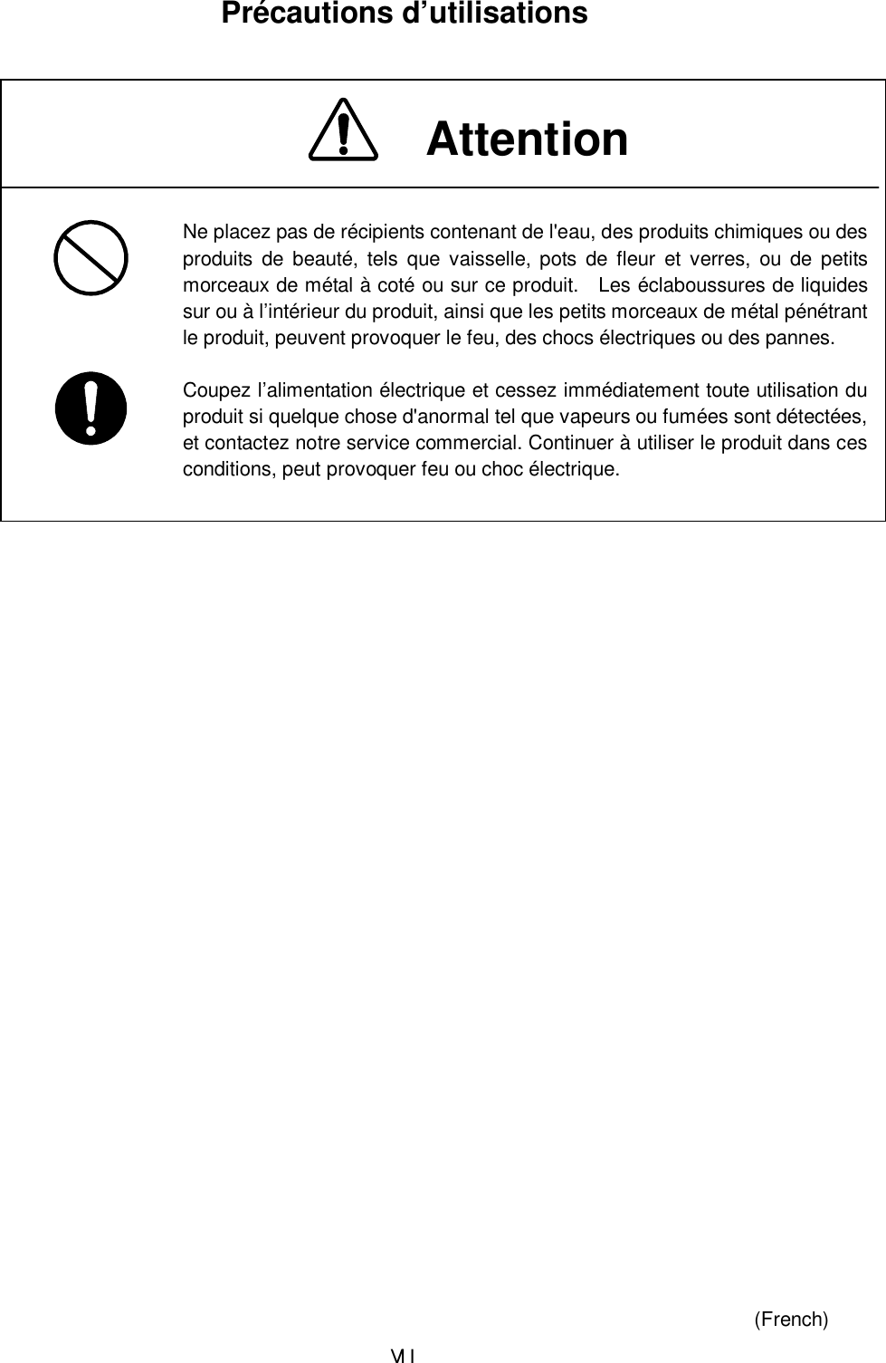
![7-134 7.7.2. The receive level and the distance In a point-to-point system, the receiving level at clear sky and the distance are related as shown in Figure 7-41. Figure 7-41 Receiving Level and Distance (QPSK) -90-80-70-60-50-40-30-20-1001 10 100 1000 10000Distance[m]Receiving Level [dBm]Transmission level (QPSK) 14 [dBm] Free space loss Lp[dB]Frequency 26 [GHz]Antenna gain[TX+RX]TX WT Antenna Gain:31dBiTYPRX WT Antenna Gain:31dBiTYP62 [dBi] λπdLp 4log20 HzfmcmλReceiving level Maximum receiving level Minimum receiving level](https://usermanual.wiki/Japan-Radio/NTG337-XL0/User-Guide-1043348-Page-157.png)
![7-135 Figure 7-42 Receiving Level and Distance (16QAM) -80-70-60-50-40-30-20-1001 10 100 1000 10000Distance[m]Receiving Level [dBm]Transmission level (16QAM) 14 [dBm] Free space loss Lp[dB]Frequency 26 [GHz]Antenna gain[TX+RX]TX WT Antenna Gain:31dBiTYPRX WT Antenna Gain:31dBiTYP62 [dBi] λπdLp 4log20 HzfmcmλMaximum receiving level Minimum receiving level Receiving level](https://usermanual.wiki/Japan-Radio/NTG337-XL0/User-Guide-1043348-Page-158.png)
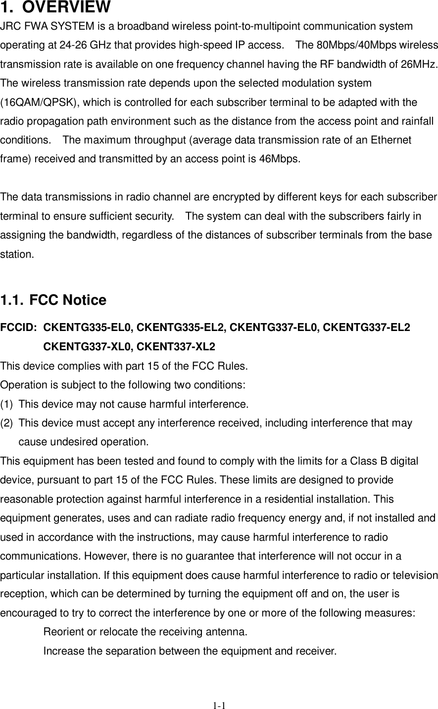
![8-150 8. Standard Tools to be Used The table below lists the tools used during installation or maintenance of the units. Table 8-1 Tools Used No. Unit name Used for: Tightening torque [N•cm] Tool 1 Door M5 265 Torx driver (VESSEL T25H-120) 2 Power board M4 127 Phillips screwdriver 3 Cable clamp M4 118 Phillips screwdriver 4 Ground M4 nut 127 Socket driver (Width across flats: 7) 5 AP-IFU SC lock(cap) G3/8 nut 110 to 150 Spanner wrench (Width across flats: 22) 6 Small window M4 127 Torx driver (VESSEL T20H-120) 7 Mounting bracket M6 850 Allen wrench (Width across flats: 5) 8 WT Ethernet cable Crimping tool for RJ-45 (Release-after-crimp type) 9 AP-RFU (Omni) Mounting bracket axis tightening M6 M16 850 9410 Socket wrench (Width across flats: 24) 10 AP-RFU (Sectoral-Horn) Mounting bracket M6 850 Allen wrench (Width across flats: 5) The appropriate tightening torque is 10% of the value indicated in the table.](https://usermanual.wiki/Japan-Radio/NTG337-XL0/User-Guide-1043348-Page-173.png)