Japan Radio NTG337-XL0 User Station User Manual Manual
Japan Radio Co Ltd. User Station Manual
Manual

0
JRC FWA SYSTEM
INSTRUCTION MANUAL
Rev. 3.4
24/SEP./2008
I
Introduction
Read this instruction manual carefully before use. Be sure you fully understand the
instructions in this manual before using the equipment.
After reading, save this instruction manual and refer to it as necessary. If you have any
questions about or there is something wrong with the equipment, refer to this manual.
II
Before use
Warning Indications
This manual and the product use some icons to help you use the product properly and
prevent any damage to you and other people or property. The following icons classify the
potential damage if the indications are ignored or the product is used improperly. When
reading the manual, keep these in mind.
Examples of icons
A triangle is an alert to call your attention including a warning
or danger indication. The graphics within the triangle differs
depending on the caution. (The figure on the left shows a
caution for electrical shocks.)
icons indicate prohibition. A detailed prohibition description
is given in the vicinity of the icon. (The figure on the left
prohibits disassembly.)
icons require you to perform the item. A detailed
instruction is given in the vicinity of the icon. (The figure on the
left instruct to unplug the equipment.)
Warning labels
Do not remove, damage or alter the warning labels.
Warning
Caution
Wrong handling of this product may cause
serious personal injury or death.
Wrong handling of this product may cause
personal injury or damage to properties.
Dangerous
voltages
General
prohibitions
General
advice
Do not
disassemble
Unplug

III
Precautions in Use
Warning
Don’t place containers having
water, chemicals or cosmetics, such as
vessels, flower pots and glasses, or small pieces of metals near or on top
of this product. Liquids spilled over or into or small metal pieces getti
ng
into the product may cause fire, electrical shocks or failures.
Turn off the power and stop using the unit immediately if something
abnormal such as fumes or smoke is detected, and contact our sales
department, branch or sales offce. Continuing to use
the product as is
may cause fire or electrical shock.
IV
Cautions
This manual describes important points to operate and maintain the
equipment. Read the related sections when operating,
maintaining
and testing the unit.
Do not try to carry out a test or maintenance not
covered in this manual.
This equipment is a precision machine. A failure may occur if you do
not observe the following:
・ Do not jar or subject this equipment and the units to shocks.
・ During operation,
do not unplug the cable connected between the
WT and WT adapter. Before unplugging this cable,
first unplug the DC
jack from
the WT adapter and turn the power off.
・ Do not splash water on the WT adapter.
・ Do not use this equipment in a place with excessive dirt or dust.
Before touching a power-receiving terminal,
turn the input power off to
avoid electrical shocks.
Do not touch the rack of the WT duirng operation because it becom
es
hot.
When installing the Access Point (AP),
connect the ground wire to the
ground terminal. If the equipment is not grounded properly,
you may
get electrical shocks when the equipment becomes faulty or shorted.
When using a measuring instrument, conne
ct the ground terminal of
the measuring instrument to the ground terminal of this equipment.
If
the equipment is not grounded properly,
you may get electrical
shocks.
To avoid shock hazards,
do not open and touch the inside or
adjustment points except for maintenance or inspection.
If you modify
the equipment illegally,
you may be punished according to the Radio
Law.

V
Cautions
Don’t use organic solvent for cleaning such as thinner and benzene because
this may damage the coating. Just wipe the surface with a clean dry cloth.
Befour plugging in or unplugging the coaxial cable between the AP-RFU and
AP-IFU, turn the power off.
The DC -48V power supply voltage for AP-IFU shall be SELV or TNV-1
depending on the network environment (0 or 1) acc. to IEC62102.
The Equipment for connection to AP-IFU Ethernet-interface(RJ-45)
shall be
appropriate to connect to TNV-1 circuits.
The Equipment for connection to WT adapter PC-interface (RJ-45) shall
be
appropriate to connect to TNV-1 circuits.
For the connection WT adapter to WT and a cable suitable for outdoor
use
shall be installed.
For the connection Terminal Equipment to AP-IFU and a cables suitable
for
outdoor use shall be installed.
For the connection AP-IFU to AP-RFU and a coaxial cable suitable for
outdoor
use shall be installed.
VI
Avant usage
Indications Préventives
This manual and the product use some icons to help you use the product
properly and prevent any damage to you and other people or property. The
following icons classify the potential damage if the indications are ignored or the
product is used improperly. When reading the manual, keep these in mind.
Exemples d'icônes
Un triangle est une alerte pour attirer votre attention en cas de
danger ou de conseil de prudence. Le signe à l’interieur du
triangle diffère selon le risque. (L’exemple de gauche signale
un risque électrique.)
Les deux icônes de gauche indiquent une interdiction. Une
description plus détaillée est donnée près de l'icône (la plus à
gauche interdit le démontage.)
Ce type d’icône exige que vous exécutiez l'action Une
description plus détaillée est donnée près de l'icône (la plus à
gauche exige de debrancher le matériel avant toute opération.)
Attention
N'enlevez jamais, n’endommagez jamais et ne changez jamais les signalisation de
danger.
(French)
Danger
Prudence
Une mauvaise utilisation de ce produit peut
causer de sérieux dommages corporels ou la
mort.
Une mauvaise utilisation de ce produit peut
causer des dommages corporels ou
endommager des biens.
Le manuel d’utilisation et le produit utilisent des icônes pour vous aider à utiliser correctement le
produit et prévenir tout dommages sur vous, sur des tiers ou sur
des biens. Les icônes qui suivent,
indiquent le niveau des dommages éventuels si les précautions indiquées sont ignorées ou si le
produit est mal utilisé. Quand vous lirez le manuel d’utilisation, faites attention à ces indications.
Danger
électrique
Débranchez
Ne pas
démonter
Inter
diction
générale
Conseil
général

VII
Précautions d’utilisations
(French)
Ne placez pas de récipients contenant de l'eau, des produits chimiques ou des
produits de beauté, tels que vaisselle, pots de fleur et verres, ou de petits
morceaux de métal à coté ou sur ce produit. Les éclaboussures d
e liquides
sur ou à l’intérieur du produit, ainsi que les petits morceaux de métal pénétrant
le produit, peuvent provoquer le feu, des chocs électriques ou des pannes.
Coupez l’alimentation électrique et cessez immédiatement toute utilisation du
produit
si quelque chose d'anormal tel que vapeurs ou fumées sont détectées,
et contactez notre service commercial. Continuer à utiliser le produit dans ces
conditions, peut provoquer feu ou choc électrique.
Attention
VIII
(French)
Attention
Ce manuel décrit les points importants pour l’utilisation et la maintenance du
Matériel. Lisez les chapitres correspondants pour l’ut
ilisation, la maintenance et
le test du Matériel. N'essayez pas d'effectuer un test ou une maintenance qui ne
soit pas décrit dans ce manuel.
Cet équipement est une machine de précision. Une panne peut se produire si
vous ne vous conformez pas pas à ce qui suit :
・
Ne cognez pas et ne soumettez pas ce matériel et ses éléments à des
chocs.
・
En cours d’utilisation, ne débranchez pas le câble reliant l’interface
utilisateur du terminal sans fil et l'adaptateur WT. Avant de déconnecter ce
câble, débranchez d’
abord la prise jack DC de l'adaptateur WT et mettez
hors-tension.
・ N'éclaboussez pas l'adaptateur WT.
・
N'utilisez pas ce matériel dans un endroit excessivement sale ou
poussiéreux.
Avant de toucher à un terminal recevant l’alimentation, mettez hors-tensio
n
pour éviter des chocs électriques.
Ne touchez pas le rack du WT en cours d’utilisation parce qu'il devient chaud.
Lors de l’installation du Point d'accès, reliez le fil de terre à la masse du
terminal. Si le matériel n'est mis correctement à la masset
, vous pourriez
provoquez des chocs électriques et le matériel deviendrait défectueux ou en
court-circuit.
Lors de l’utilisation d’un instrument de mesure, reliez la masse de l'instrument
de mesure à la prise de terre du matériel. Si les matériels ne sont
pas
correctement mis à la masse, vous pouvez provoquer des chocs électriques.
Pour éviter les risques de détérioration, n'ouvrez pas et ne touchez pas
l'intérieur ou les points de réglage, excepté lors d'une maintenance ou d’une
inspection. Si vous appo
rtez des modification au matériel illégalement, vous
pouvez être poursuivi conformément aux lois en vigueur.

IX
(French)
Attention
N'utilisez pas de solva
nt organique pour le nettoyage, tel que dissolvant et
benzène parce que cela peut endommager le revêtement. Essuyez juste la
surface avec un chiffon sec et propre.
Avant de brancher ou de débrancher le câble coaxial entre AP-RFU et AP-
IFU,
mettez hors-tension.
L’alimentation DC -48V pour AP-IFU peut être SELV ou TNV-
1 en fonction du
réseau (0 ou 1) conformément à la norme IEC62102.
Le matériel de connexion à AP-
IFU par une interface Ethernet (RJ 45) devra
être relié aux circuits TNV-1.
Le Matériel de
connexion à l’adaptateur WT par l’nterface PC (RJ 45) devra être
relié aux circuits TNV-1.
Pour la connexion de l’adaptateur WT à WT, un câble adapté à l’utilisation en
plein air sera utilisé.
Pour la connexion du Terminal à AP-IFU, un câble adapté à l’
utilisation en plein
air sera utilisé.
Pour la connexion de AP-IFU à AP-
RFU un câble coaxial adapté à l’utilisation
en plein air sera utilisé.
X
Prima dell’utilizzo
Seguire attentamente le avvertenze
Questo manuale ed il prodotto usano delle icone per aiutarLa a utilizzare propriamente il
prodotto e prevengono eventuali danni a Lei o ad altre persone o beni materiale derivanti
dal cattivo utilizzo di questo prodotto. Le icone seguenti classificano il pericolo ed il danno
potenziale nel caso in cui le indicazioni fossero ignorate o nel caso in cui il prodotto fosse
usato impropriamente. Seguire attentamente le avvertenze.
Esempi di icone
Un triangolo è un allarme per chiamare la Sua attenzione. Esso
include un avvertimento o indicazione di pericolo. Le grafiche
all'interno del triangolo differiscono dal grado di cautela. (La
figura a sinistra mostra pericolo per shock elettrici.)
icone indicano proibizione. Una descrizione di proibizione
particolareggiata è data accanto all’ icona. (La figura sulla
sinistraproibisce lo smontaggio del prodotto.)
●icone La invitano a compiere il gesto indicato. Una
descrizione piu’ dettagliata è data accanto all’icona. (La figura
sulla sinistra richiede di scollegare il prodotto.)
Segnali di avvertimento
Si prega di non rimouvere, alterare o danneggiare tali etichette
(Italian)
Pericolo
Avvertenza
Una cattiva utilizzazione di questo prodotto puo’
provocare seri danni a persone mettendo i
suddetti in pericolo di vita
Una cattiva utilizzazione di questo prodotto puo’
provocare seri danni a persone o cose
Tensioni
pericolo
se
Proibizioni
Generali
Consiglio
Generale
Non smonti
Unplug

XI
Precauzioni d’uso
(Italian)
Spenga immediatamente il prodotto se qualche anomalia come fumo o
vapori sono emanati dal prodotto. e contatti immediatamente il nostro ufficio
di vendite. Continuare ad usare il prodotto
in tali condizioni può causare
inizi di incendio o shock elettrici.
Non metta contenitori d’acqua, prodotti chimici o cosmetici, come vasi,
pentole ed occhiali o piccoli pezzi di metalli vicino o in cima a questo
prodotto. Liquidi versati sopra o al
l’interno del prodotto, piccoli elementi
metallici inseriti all’interno del prodotto possono provocare shock elettreici o
malfunzionamenti.
Pericoli
XII
(Italian)
Avvertenze
Questo manuale descrive importanti precauzioni punti per l’utilizzo e la
manutenzione del prodotto. Legga le sezioni relative durante l’uso, in veglia o
durante la prova dell'unità.
Non tenti di eseguire prove o operazioni non
descritte in questo manuale.
Q
uesta attrezzatura è una macchina di precisione. Possono verificarsi
malfunzionamenti se non osserva le seguenti precauzioni:
・ Non sottoponga questa attrezzatura a colpi o cadute
・ Durante l’uso, non faccia scolleghi il cavo connesso t
ra l’unità senza fili e
l'adattatore di WT.
Prima di scollegare il dispositivo, rimuova il connettore dall'adattatore di WT
e in seguito spenga il dispositivo.
・ Non metta a contatto l’adattatore WT con acqua.
・ Non usi questa attrezzatura in un luoghi po
lverosi o poco puliti. Prima di
toccare un –
terminale di potenza ricevente, spenga il dispositivo per evitare
evitare shock elettrici.
Non tocchi l'intelaiatura del dispositivo WT poiche esso puo’ produrre calore.
Quando installa il punto di accesso, c
onnetta il filo di massa al terminale di
terra. Se l'attrezzatura non è collegata a terra propriamente, Lei puo’ ricevere
shock elettrici quando l'attrezzatura diviene difettosa o in corto circuito.
Quando usa un strumento di misura, connetta il termina
le di massa dello
strumento di misura al terminale di massa di questa attrezzatura. Se
l'attrezzatura non è collegata a terra propriamente, Lei puo’ ricevere shock
elettrici.
Per evitare pericoli di shock, non apra e non tocchi l'interno del dispositiv
o o I
punti di rettifica eccetto durante manutenzione o ispezione.
Se Lei modifica
illegalmente l'attrezzatura, Lei può essere punito secondo la Legge Radio

XIII
(Italian)
Cautele
Non usi solventi organici come diluente e benzene
per pulire il dispositivo
perché questo può danneggiarne il rivestimento. Asciugi la superficie con una
stoffa asciutta e pulita.
Prima di collegare o scollegare il cavo coassiale tra l'AP-RFU ed AP-
IFU,
spenga il dispositivo.
La DC -48V tensione di alimentazione elettrica per AP-IFU sara’ SELV o TNV-
1
a seconda della rete elettrica utilizzata (0 o 1) con riferimento a IEC62102.
L'Attrezzatura per il collegamento ad AP-IFU Ethernet-interface(RJ-45)
sarà adatto per connettere ai circuiti di TNV-1.
L'Attrezzatura per il collegamento all'adattatore di WT PC-interface(RJ-
45) deve
essere compatibile con una connessione ai circuiti di TNV-1
Per il collegamento tra adattatore WTe WT dovrà essere utilizzato un cavo
appropriato per uso esterno.
Per il collegamento dell’attrezzatura completa al AP-
IFU dovrà essere utilizzato
un cavo adatto ad uso esterno
Per il collegamento tra AP-IFU e AP-
RFU dovrà essere utilizzato un cavo
coassiale appropriato per uso esterno.
XIV
Bitte beachten vor der Inbetriebnahme
Warnhinweise und Kennzeichnungen
In dDiesem Handbuch und bei der Verwendung des Produktes werden
Kennzeichen benutzt, die Ihnen helfen sollen das Produkt richtig einzusetzen
und gleichzeitig verhindern sollen, dass Personenschäden entstehen. Bitte
lesen Sie die folgenden Hinweise sorgfältig und beachten die Angaben beim
Lesen des Handbuchs.
Beispiele für Kennzeichen und ihre Bedeutung
Ein Dreieck dient als Alarmzeichen und Warnung, um ihre
Aufmerksamkeit auf Gefahren zu lenken. Das Symbol im
Dreieck unterscheidet die Art der Gefahren (Die Figur auf
der Linke zeigt eine Warnung vor elektrischer
Hochspannung)
Kreisförmige Kennzeichen weisen auf ein Verbot hin.
Eine Verbotsbeschreibung wird in der Unterschrift des
Kennzeichens gegeben. (Die Figur links zum Beispiel
verbietet eine Demontage)
● Gefüllte kreisförmige Kennzeichen weisen Sie auf eine
beabsichtigtes Handlung hin. Sie werden aufgefordert die
Handlung durchzuführen. Eine ausführliche
Anweisungsbeschreibung wird in der Nähe des
Kennzeichens gegeben. (In der Figur links werden Sie
aufgefordert den Stecker aus der Steckdose zu entfernen)
Warnkennzeichnungen
Bitte entfernen, verändern oder beschädigen Sie die Kennzeichnung nicht.
(German)
Warnung
Caution
Falsche
Handhabung dieses Produktes kann
zu ernsthaften Personenschäden und sogar zum
Tod führen.
Falsche
Handhabung dieses Produktes kann
zu ernsthaften Personenschäden oder Schäden
an anderen Gegenständen führen.
Gefährliche
Hochspannung
Stecken Sie
aus
Nehmen Sie
nicht
auseinander
Allgemein
Verbote
Allgemeiner
Rat

XV
Vorkehrungen beim Gebrauch
(German)
Schalten Sie das Gerät unbedingt aus, wenn Sie ungewöhnliche Rauch
-
oder Dampfentwicklung beobachten, und kontaktieren Sie unseren zentralen
Vertrieb,
eine Filiale oder ein Vertriebsbüro in Ihrer Nähe. In diesem Fall darf
das Gerät nicht weiterverwendet werden. Eine weitere Benutzung kann zu
Bränden und elektrischen Kurzschlüssen führen.
Bitte stellen Sie keine Wasserbehälter, Chemikalien oder Kosmetik
a, wie
zum Beispiel Gefäße, Blumenvasen, Gläser oder kleine Metallstücke auf
oder in die Nähe des Produktes. Flüssigkeiten oder kleine Metallteile, die in
das Garät gelangen, könnten Brände, Kurzschlüsse oder Fehlfunktionen
hervorrufen.
Warnung
XVI
(German)
Vorsicht
Dieses Handbuch enthält wichtige Informationen zur Bedienung und Wartung
des Gerätes. Lesen Sie bitte die entsprechenden Abschnitte bevor Sie das
Gerä
t in Betrieb bedienen, warten oder in anderer Weise testen. Bitte führen Sie
keine Tests durch, die im Manual nicht beschrieben sind.
Dieses Gerät ist ein hochgenaues Instrument.
・
Fehler können auftreten sollte das Gerät: Stössen oder starken
Erschütterungen ausgesetz wird.
・
Während des Betriebes muss die Kabelverbindung zwischen dem
Bedienelement des Funkterminal und dem WT-Adapter nicht gelöst werden.
・ Um das Kabel zu entfernen, lösen Sie zuerst die DC-Versorgung
Stecker
des WT-Adapters und schalten das Gerät ab.
・ Der WT-Adapter darf mit Wasser nicht in Berührung kommen.
・ Vermeiden Sie den Betrieb des Gerätes in Umgebungen mit hoher Staub-
und Schmutzbelastung.
Berühren Sie den Rahmen des WT’s während des Betriebes auf keinen Fall, da
dieser Teil sehr heiss wird.
Wenn Sie den Access Point installieren, verbinden Sie zuerst den Erdungsdraht
mit dem Erdungsanschluss des Gerätes. Ungenügende Erdung des Gerätes,
kann im Falle von Fehlfunktionen oder Kurzschlüssen zu Stromschlägen führen.
Wenn Sie ein weiteres
Meßgerät einsetzen, verbinden Sie bitte den
Erdungsanschluss des Messgerätes sorgfältig mit dem Erdungsanschluss des
Gerätes. Ungenügende Erdung des Gerätes, kann zu Stromschlägen führen.
Bitte öffnen oder berühren Sie das Innenleben sowie die Einstellun
gsmittel des
Gerätes nicht, ausser im Falle von Wartungsarbeiten oder Inspektionen.
Wenn Sie unerlaubt Änderungen am Gerät vornehmen, zieht dies Massnahmen
in Anwendung des „RADIO Gesetzes“ nach sich.

XVII
(German)
Cautions
Benutzen Sie kein organische Lösungsmittel, wie Verdünner und Benzole zur
Reinigung, we
il dies der Oberfläche des Gerätes beschädigen könnte.
Reinigen Sie die Oberfläche nur mit einem sauberen trockenen Stofftuch.
Bitte schalten Sie das Gerät aus, bevor Sie das Koaxialkabel zwischen AP-
RFU
und AP-IFU anschliessen oder entfernen.
Nach IEC62102 sollte die 48V DC–Spannngsversorgung für den AP-
IFU SELV
oder TNV-1 in Abhängigkeit von der Netzwerkumgebung ( 0 oder 1) sein.
Die Ausrüstung für Verbindung zu AP-IFU Ethernet-interface(RJ-45)
, wird
geeignet sein, sich in Verbindung mit TNV-1-Schaltungen zu setzen.
Die die Verbindung des WT-
Adapters zum WT sollte ein Kabel verwendet
werden, dass für den Aussenbereich geeignet ist.
Für die Verbindung vom WT-
Adapter zum WT sollte ein Kabel für
Aussenanwendungen gewählt werden.
Für die Verbindung vom Terminal des Gerätes zum AP-
IFU sollte ein Kabel für
Aussenanwendungen gewählt werden.
Für die Verbindung AP-IFU zu AP-
RFU sollte ein Koaxialkabel für den
Aussenbereich installiert werden.
XVIII
CONTENTS
Introduction......................................................................................................................................I
Before use ......................................................................................................................................II
Precautions in Use ........................................................................................................................III
Avant usage.................................................................................................................................. VI
Précautions d’utilisations............................................................................................................. VII
Prima dell’utilizzo........................................................................................................................... X
Precauzioni d’uso ......................................................................................................................... XI
Bitte beachten vor der Inbetriebnahme......................................................................................XIV
Vorkehrungen beim Gebrauch ....................................................................................................XV
CONTENTS..............................................................................................................................XVIII
1. OVERVIEW.......................................................................................................................... 1-1
1.1. FCC Notice............................................................................................................... 1-1
1.2. CERTIFICATION NOTE FROM INDUSTRY CANADA............................................ 1-2
1.3. System Configuration............................................................................................... 1-2
1.4. Deployment Schemes.............................................................................................. 1-3
1.5. Components ............................................................................................................. 1-4
2. Specifications....................................................................................................................... 2-7
2.1. General..................................................................................................................... 2-7
2.2. External Views of the Units ...................................................................................... 2-9
2.2.1. AP-RFU (Omni Antenna)...................................................................................... 2-9
2.2.1.1. AP-RFU (Omni Antenna) Nameplate.......................................................... 2-10
2.2.1.2. AP-RFU (Omni Antenna) Mounting Bracket ................................................2-11
2.2.2. AP-RFU (Sectoral-Horn Antenna) ...................................................................... 2-12
2.2.2.1. AP-RFU (Sectoral-Horn Antenna) Nameplate ............................................ 2-13
2.2.2.2. AP-RFU (Sectoral-Horn Antenna) Mounting Bracket.................................. 2-14
2.2.3. AP-IFU ................................................................................................................ 2-15
2.2.3.1. AP-IFU Nameplate ...................................................................................... 2-16
2.2.4. WT ...................................................................................................................... 2-17
2.2.4.1. WT Nameplate............................................................................................. 2-18
2.2.4.2. WT Mounting Bracket.................................................................................. 2-19
2.2.5. WT (External Antenna) ....................................................................................... 2-20
2.2.5.1. WT (External Antenna) Nameplate ............................................................. 2-21
2.2.6. WT Adapter......................................................................................................... 2-22
2.2.6.1. WT Adapter Nameplate............................................................................... 2-22
2.2.7. WT AC Adapter................................................................................................... 2-23
XIX
2.2.8. Antenna direction adjustment tool...................................................................... 2-24
3. AP ...................................................................................................................................... 3-25
3.1. AP-RFU .................................................................................................................. 3-25
3.1.1. Overview............................................................................................................. 3-25
3.1.2. Antenna section.................................................................................................. 3-25
3.1.3. RF section........................................................................................................... 3-25
3.1.4. IF section ............................................................................................................ 3-25
3.1.5. Operations and Indications................................................................................. 3-26
3.1.5.1. Indications ................................................................................................... 3-26
3.1.5.2. Switches ...................................................................................................... 3-26
3.1.6. Terminals............................................................................................................. 3-27
3.1.6.1. Omni Antenna.............................................................................................. 3-27
3.1.6.2. Sectoral-Horn Antenna................................................................................ 3-27
3.2. AP-IFU.................................................................................................................... 3-28
3.2.1. Overview............................................................................................................. 3-28
3.2.2. IF section ............................................................................................................ 3-28
3.2.3. Operations and Indications................................................................................. 3-30
3.2.3.1. Indications ................................................................................................... 3-30
3.2.3.2. Switches ...................................................................................................... 3-32
3.2.3.3. Terminals ..................................................................................................... 3-33
4. WT ..................................................................................................................................... 4-36
4.1. WT.......................................................................................................................... 4-36
4.1.1. Overview............................................................................................................. 4-36
4.1.2. Antenna section.................................................................................................. 4-36
4.1.3. RF section........................................................................................................... 4-36
4.1.4. IF section ............................................................................................................ 4-36
4.1.5. Digital section ..................................................................................................... 4-37
4.1.6. Interface section ................................................................................................. 4-37
4.1.7. Power supply ...................................................................................................... 4-37
4.1.8. Operations and Indications................................................................................. 4-39
4.1.8.1. Indications ................................................................................................... 4-39
4.1.8.2. Switches ...................................................................................................... 4-41
4.1.8.3. Terminals ..................................................................................................... 4-42
4.1.8.3.1. WT............................................................................................................4-42
4.1.8.3.2. WT Adapter ..............................................................................................4-43
5. CONSTRUCTING A POINT-TO-MULTIPOINT SYSTEM (AP) ......................................... 5-45
XX
5.1. Overview................................................................................................................. 5-45
5.2. Installing the AP-RFU and AP-IFU ......................................................................... 5-46
5.2.1. Installing the AP-RFU (Omni Antenna)............................................................... 5-46
5.2.2. Installing the AP-RFU (Sectoral-Horn Antenna) ................................................. 5-48
5.2.3. Setting AP-RFU(Sectoral-Horn Antenna)for Vertical or Horizontal Polarization 5-51
5.2.4. installing the AP-IFU ........................................................................................... 5-52
5.2.4.1. Installing the AP-IFU.................................................................................... 5-52
5.2.4.2. Example of Installing the AP-IFU ................................................................ 5-53
5.2.4.3. Opening and Closing the AP-IFU Cover ..................................................... 5-54
5.3. Adjusting the Direction of the AP-RFU................................................................... 5-55
5.3.1. Adjusting the Direction of the AP-RFU (Omni Antenna)..................................... 5-55
5.3.2. Adjusting the Direction of the AP-RFU (Sectoral-Horn Antenna)....................... 5-55
5.3.3. Direction adjustment of the antenna................................................................... 5-56
5.4. Connecting a Cable between AP-RFU and AP-IFU............................................... 5-57
5.4.1. AP-RFU (Omni Antenna).................................................................................... 5-57
5.4.2. AP-RFU (Sectoral-Horn Antenna) ...................................................................... 5-58
5.5. Connecting Cables from the AP-IFU to external.................................................... 5-59
5.5.1. Connecting the Power cable connector.............................................................. 5-61
5.6. The confirmation of AP-IFU.................................................................................... 5-63
5.7. Waterproofing Connectors ..................................................................................... 5-64
5.7.1. Self Bonding tape ............................................................................................... 5-64
5.8. Connecting the AP Local Management Tool.......................................................... 5-66
5.9. Configure the AP parameters................................................................................. 5-67
5.9.1. AP Local management tool ................................................................................ 5-67
5.9.1.1. Configure the AP network parameters........................................................ 5-67
5.9.1.2. Reset the AP................................................................................................ 5-68
5.9.1.3. Measure the cable loss ............................................................................... 5-69
5.9.2. Register the AP ID number to OpS .................................................................... 5-71
5.10. Check sheet of AP Installation ............................................................................... 5-72
6. CONSTRUCTING A POINT-TO-MULTIPOINT SYSTEM (WT) ........................................ 6-73
6.1. Overview................................................................................................................. 6-73
6.2. OpS ........................................................................................................................ 6-74
6.2.1. Register the WT ID number to AP...................................................................... 6-74
6.3. Connecting the WT Local Management Tool......................................................... 6-76
6.4. WT Local management tool ................................................................................... 6-76
6.4.1. Configure the WT................................................................................................ 6-76
XXI
6.5. Installing the WT..................................................................................................... 6-77
6.5.1. Installing the WT................................................................................................. 6-77
6.5.2. Example of Installing the WT.............................................................................. 6-79
6.5.3. Setting the WT for Vertical or Horizontal Polarization ........................................ 6-80
6.6. Installing the WT (External Antenna)...................................................................... 6-81
6.6.1. Installing the WT (ExternalΦ30cm Antenna) ...................................................... 6-81
6.6.2. Installing the WT (ExternalΦ60cm Antenna) ...................................................... 6-85
6.7. Adjusting the Direction of the WT........................................................................... 6-89
6.7.1. Connecting the WT Local Management Tool ..................................................... 6-90
6.7.2. Roughly Adjusting the Direction ......................................................................... 6-91
6.7.3. Finely Adjusting the Direction............................................................................. 6-92
6.7.4. The receive level and the distance..................................................................... 6-93
6.8. Installing the WT Adapter ....................................................................................... 6-97
6.9. Connecting Cables to the WT................................................................................ 6-98
6.10. Waterproofing WT small window.......................................................................... 6-100
6.11. When you use the cable with the LAP sheath for outdoor................................... 6-104
6.12. Waterproofing Without Using a Cold-Shrinkable Tube ........................................ 6-106
6.13. Testing .................................................................................................................. 6-108
6.13.1. Perform a continuity test............................................................................ 6-108
6.13.2. Measure the packet loss rate.................................................................... 6-109
6.14. Check sheet of WT Construction ..........................................................................6-110
7. CONSTRUCTING A POINT-TO-POINT SYSTEM ...........................................................7-111
7.1. Overview(WT Construction flow)...........................................................................7-111
7.2. Connecting the WT Local Management Tool........................................................7-112
7.3. Configure the WT(master).....................................................................................7-113
7.4. Configure the WT(slave) .......................................................................................7-115
7.5. Installing the WT....................................................................................................7-116
7.5.1. Installing the WT(master/slave).........................................................................7-116
7.5.2. Example of Installing the WT.............................................................................7-118
7.5.3. Setting the WT for Vertical or Horizontal Polarization .......................................7-119
7.6. Installing the WT (External Antenna).................................................................... 7-120
7.6.1. Installing the WT (ExternalΦ30cm Antenna) .................................................... 7-120
7.6.2. Installing the WT (ExternalΦ60cm Antenna) .................................................... 7-124
7.7. Adjusting the Direction of the WT......................................................................... 7-128
7.7.1. Adjusting the Direction of the WT..................................................................... 7-128
7.7.1.1. Connecting the WT Local Management Tool............................................ 7-129
XXII
7.7.1.2. Roughly Adjusting the Direction ................................................................ 7-132
7.7.1.3. Finely Adjusting the Direction.................................................................... 7-133
7.7.2. The receive level and the distance................................................................... 7-134
7.8. Installing the WT Adapter(master/slave).............................................................. 7-136
7.9. Connecting Cables to the WT(master/slave)....................................................... 7-137
7.10. Waterproofing WT small window.......................................................................... 7-139
7.11. When you use the cable with the LAP sheath for outdoor................................... 7-142
7.12. Waterproofing Without Using a Cold-Shrinkable Tube ........................................ 7-143
7.13. Testing .................................................................................................................. 7-146
7.13.1. Ping test..................................................................................................... 7-146
7.13.2. Measure the packet loss rate (with WT Local mnagement tool)............... 7-147
7.13.3. Measure the packet loss rate (with OpS).................................................. 7-148
7.14. Check sheet of Point to Point Construction ......................................................... 7-149
8. Standard Tools to be Used .............................................................................................. 8-150
9. INITIAL VALUES.............................................................................................................. 9-151
9.1. Point to Multipoint system .................................................................................... 9-151
9.1.1. Initial values for AP parameters (Point to Multipoint System) .......................... 9-151
9.1.2. Initial values for WT(1 - 239) parameters (Point to Multipoint system)............ 9-153
9.1.3. Initial values for VID(2 - 4094) table parameters (Point to Multipoint system). 9-153
9.1.4. Initial values for AP-IFU swiches...................................................................... 9-154
9.1.5. Initial values for WT(Master) parameters (Point to point System) ................... 9-155
9.1.6. Initial values for WT (Slave) parameters (Point to point System) .................... 9-156
10. System example Point to Multipoint system ...................................................... 10-157
11. System example Point to Point ...........................................................................11-161
1-1
1. OVERVIEW
JRC FWA SYSTEM is a broadband wireless point-to-multipoint communication system
operating at 24-26 GHz that provides high-speed IP access. The 80Mbps/40Mbps wireless
transmission rate is available on one frequency channel having the RF bandwidth of 26MHz.
The wireless transmission rate depends upon the selected modulation system
(16QAM/QPSK), which is controlled for each subscriber terminal to be adapted with the
radio propagation path environment such as the distance from the access point and rainfall
conditions. The maximum throughput (average data transmission rate of an Ethernet
frame) received and transmitted by an access point is 46Mbps.
The data transmissions in radio channel are encrypted by different keys for each subscriber
terminal to ensure sufficient security. The system can deal with the subscribers fairly in
assigning the bandwidth, regardless of the distances of subscriber terminals from the base
station.
1.1. FCC Notice
FCCID: CKENTG335-EL0, CKENTG335-EL2, CKENTG337-EL0, CKENTG337-EL2
CKENTG337-XL0, CKENT337-XL2
This device complies with part 15 of the FCC Rules.
Operation is subject to the following two conditions:
(1) This device may not cause harmful interference.
(2) This device must accept any interference received, including interference that may
cause undesired operation.
This equipment has been tested and found to comply with the limits for a Class B digital
device, pursuant to part 15 of the FCC Rules. These limits are designed to provide
reasonable protection against harmful interference in a residential installation. This
equipment generates, uses and can radiate radio frequency energy and, if not installed and
used in accordance with the instructions, may cause harmful interference to radio
communications. However, there is no guarantee that interference will not occur in a
particular installation. If this equipment does cause harmful interference to radio or television
reception, which can be determined by turning the equipment off and on, the user is
encouraged to try to correct the interference by one or more of the following measures:
Reorient or relocate the receiving antenna.
Increase the separation between the equipment and receiver.
1-2
Connect the equipment into an outlet on a circuit different from that to which the
receiver is connected.
Consult the dealer or an experienced radio/TV technician for help.
Caution . Changes or modifications to this equipment could void the user’s authority to
operate the equipment.
1.2. CERTIFICATION NOTE FROM INDUSTRY CANADA
ICID: 768B-NTG335L0, 768B-NTG337L0, 768B-NTG335L2, 768B-NTG337L2
While this equipment meets the technical requirements for its operation in its rated paired
block arrangement, this block arrangement is different than the 40 + 40 MHz block
arrangement prescribed in documents RSS-191 and SRSP-324.25. The operation of this
equipment IS NOT permitted if the out-of-band and spurious emission limits are not met at
the edge of any contiguous licensed spectrum. It should be noted that all current relevant
spectrum policies, licensing procedures and technical requirements are still applicable. For
additional information, please contact the local Industry Canada office.
Access Point
This Class A digital apparatus complies with Canadian ICES-003.
Cet appareil numérique de la classe A est conforme à la norme NMB-003 du Canada.
Wireless Terminal
This Class B digital apparatus complies with Canadian ICES-003.
Cet appareil numérique de la classe B est conforme à la norme NMB-003 du Canada.
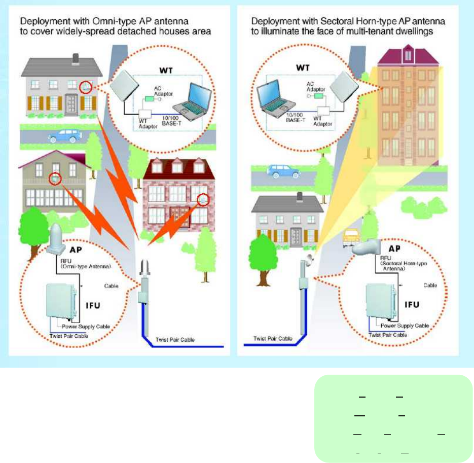
1.3. System Configuration
One Access Point (AP) has the capacity of linking with up to 239 subscriber terminals to
configure a point-to-multipoint (P-MP) communications system. An omni-directional
antenna (with horizontal directivity of 360°) mainly for a residential area of detached houses
and a Sectoral-Horn-type antenna (90° × 10° directivity) mainly for multi-tenant building are
available.
Wireless Terminal (WT), including the antenna and all the electric circuits, is designed
compactly (19cm x 19cm x 7cm) and can easily be installed at any outside places of
residential houses. WT is connected to a PC through one LAN cable and supplied with
power through a tiny power supply adapter.
1-3
Second layer isolation of subscriber traffic is provided by 802.1Q VLAN-tag. Broadband
Access Server (BAS) terminates access layer functions and relay user traffic to IP backbone
network.
The Operation System (OpS) allowing the installation and registration of subscriber
terminals and the supervision of its operational status is optionally available.
1.4. Deployment Schemes
Figure 1-1 is deployment schemes of JRC FWA systems.
Figure 1-1 Deployment Schemes of JRC FWA Systems
AP: Access Point
WT: Wireless Terminal
RFU: Radio Frequency Unit
IFU: Interface Unit
IFU IFU

1-4
1.5. Components
Table 1-1 Components
No.
Name Model Description
1 AP-RFU(Sectoral-Horn) NTG-335<1><2><4> The AP-RFU (Sectoral-Horn) is a radio unit
that accommodates both the antenna and
transceiver in the same housing. Connecting
an AP-IFU to the AP-RFU constitutes an AP
and allows connecting multiple WTs over radio
links.
2 AP-RFU(Omni) NTG-339<1><2><4> The AP-RFU (Omni) is a radio unit that
accommodates both the antenna and
transceiver in the same housing. Connecting an
AP-IFU to the AP-RFU constitutes an AP and
allows connecting multiple WTs over radio links.
3 AP-IFU NTJ-111<4> The AP-IFU converts Ethernet frames into radio
signals and vice versa. Connecting an AP-RFU
to the AP-IFU constitutes an AP. It supports the
100BASE-TX electrical network interface to
allow connecting a unit such as a router.
Assigning an IP address for maintenance and
monitoring allows transmission and reception of
maintenance signals via SNMP through a
network interface.
3.1
DC-48V connector (AP) NRW-203-PF8-ULCSATUV
The DC -48V connector (AP) is for an external
power cable. The connector is connected to the
terminal for the AP-IFU power supply
connector.
4 WT NTG-337<1><3><4> The WT is a radio unit that accommodates all
the antenna, radio transceiver, signal processor
and interface section in the same housing. It
supports 10BASE-T and 100BASE-TX user
interfaces to connect a personal computer and
hub.
4.1
WT adapter NQD-2049<4> The WT adapter sends both Ethernet signals

1-5
from the PC and 24 VDC from the AC
adapter to the WT through an Ethernet cable.
It also sends signals from the WT to the PC.
NBG-317<3> 4.2
AC adapter
(100V to 240V AC) NBG-399R
The AC adapter supplies 24 VDC to the WT.
NBG-399R is latest.
4.3
AC adapter cable H-7ZCCM0132
or
H-7ZCCM0135
It use for NGB-399R.
H-7ZCCM0132:Atype (USA)
H-7ZCCM0135:Ctype (Europe)
MPBX39464A 4.4
WT mounting bracket
MPBX44142
The WT mounting bracket is used to mount
the WT on a pole or similar object.
MPBX44142 is latest.
4.4
CS Sleave
(WT aperture)
MPPK31288 The cold-shrinkable tube is mounted on the
small window of the WT to make the WT
waterproof and dustproof.
5 Antenna direction
adjustment tool
NKK-163 There are antenna direction adjustment tools
for the AP and WT.
6 JRC Local management tool
CD-ROM
H-7YZCM5074B AP Local management tool 、WT Local
management tool、AP Local management
tool instruction manual and WT Local
management tool instruction manual are
included in this CD-ROM.
6.1
AP Local management tool
H-7YZCM5053A Connecting a computer with this software
installed to the AP-IFU allows you to execute
the maintenance and management functions
for the AP. Use the AP local management
cable to connect between the PC and
AP-IFU.
6.2
WT Local management tool
H-7YZCM5052A Connecting a computer with this software
installed to the WT allows you to execute the
maintenance and management functions for
the WT. Use an Ethernet cable to connect
between the PC and WT.
6.3
AP Local management tool
instruction manual
H-7YZCM5061 instruction manual of AP Local management
tool

1-6
6.4
WT Local management tool
instruction manual
H-7YZCM5060 instruction manual of WT Local management
tool
H-7ZCCM5040A 7 AP local management cable
H-7ZCCM0121A
Use this cable to connect a PC with the AP
local management tool installed to the
AP-IFU.
H-7ZCCM0121A is latest.
8 PMP-OpS
(CD-ROM)
H-7YZCM5076C The PMP-OpS is included in this CD-ROM.
8.1
PMP-OpS H-7YZCM5056A The PMP-OpS (Point-to-Multipoint Operation
System) is an SNMP manager dedicated to a
JRC FWA system with a point-to-multipoint
configuration.
8.2
PMP-OpS
INSTRUCTION MANUAL
H-7YZCM5062 The PMP-OpS INSTRUCTION MANUAL
9 PP-OpS (CD-ROM) H-7YZCM5077B The PP-OpS is included in this CD-ROM.
9.1
PP-OpS H-7YZCM5055A The PP-OpS (Point-to-Point Operation
System) is an SNMP manager dedicated to a
JRC FWA system with a point-to-point
configuration.
9.2
PP-OpS
INSTRUCTION MANUAL
H-7YZCM5063 The PP-OpS INSTRUCTION MANUAL
10
JRC FWA SYSTEM
INSTRUCTION MANUAL
(CD-ROM)
H-7YZCM0102C INSTRUCTION MANUAL is included in this
CD-ROM.
10.1
JRC FWA SYSTEM
INSTRUCTION MANUAL
H-7YZCM0101B INSTRUCTION MANUAL.
Subject to change without notice.
<1> Frequency Type
L0 : 24.050∼24.549GHz
L1 : 24.549∼24.997GHz
L2 : 24.997∼25.445GHz
H1 : 25.557∼26.005GHz
H2 : 26.005∼26.453GHz
X0 : 24.050∼24.549GHz (External Antenna)
X2 : 24.997∼25.445GHz (External Antenna)
<2> Antenna Type
H : Horizontal Polarization
V : Vertical Polarization
<3> AC Power Cable Piug Type
E : Europe
U : USA
<4> RoHS
Blank : non RoHS
R : RoHS

2-7
2. Specifications
2.1. General
Table 2-1 JRC FWA SYSTEM Specifications
Point to Multipoint System
Item AP WT Point to Point System
Frequency Band EL0 EL1 EL2 EH1 EH2
[GHz]
24.050-24.549 24.549-24.997 24.997-25.445 25.557-26.005 26.005-26.453
Duplex/multiple
access TDD/TDMA TDD
Modulation system QPSK/16QAM
Symbol rate 20M symbol/s
Radio Transmission
rate QPSK:40Mbps 16QAM:80Mbps QPSK:40Mbps 16QAM:80Mbps
(Data throughput) (Max.23Mbps) (Max.46Mbps) (Max.16Mbps) (Max.32Mbps)
Occupied bandwidth 26MHz (QPSK/16QAM)
Channel spacing 28MHz
Transmit output power
QPSK:+14dBm QPSK (ATPC):
-6 to +14dBm QPSK: -6 to +14dBm
16QAM (ATPC):
-8.5 to +11.5dBm
16QAM: -8.5 to +11.5dBm
Frequency Stability ±10ppm
Transmitter spurious
emission -30dB/MHz or less
RF spectrum mask QPSK:ETSI Type A
16QAM:ETSI Type B
Minimum receiving
level (BER=10-6)
After an error
correction
QPSK: -79dBm or less 16QAM: -69dBm or less
Antenna type and gain
Omni: 6.5dBi High-gain flat antenna: 31dBi
(typ) 90°X10°Sectoral Horn:15.5dBi External Antenna
: 35.7dBi(30cm) / 41.1dBi(60cm) / 44.6dBi(90cm)
/ 46.9dBi(120cm)
Max number of WTs 239 WTs per AP -
Interface 100BASE-TX 10BASE-T/100BASE-TX
MAC processing VLAN (IEEE802.1Q)
User data are distributed by using
VLAN-TAG to each WT -
MAC address filtering
enable disable
SNMP (agent) Remote operation is possible by OpS (option).
SNMP V2, Private MIB, VLAN TAG (IEEE802.1q)
AP setup/control
WT setup/control
Test
Alarm log
WT Operating Status List
Remote downloading
Bandwidth Table
Parameter setup/Control (Master)
Alarm Log (Master)
Traffic information (Master)
Network configuration (Master)
Local management Local management is possible by Local management tool (option).
AP: Serial interface(Exclusive cable use)
WT: Ether interface Master/Slave: Ether interface
Setup (AP,WT)
Control (AP,WT)
Radio link monitor (WT)
Log (AP,WT)
Tool Setup (AP,WT)
Setup
Control
Radio link monitor
Log
Tool Setup (AP,WT)

2-8
Power -48 V DC 100 to 240 V AC
35W (MAX) 35VA (MAX)
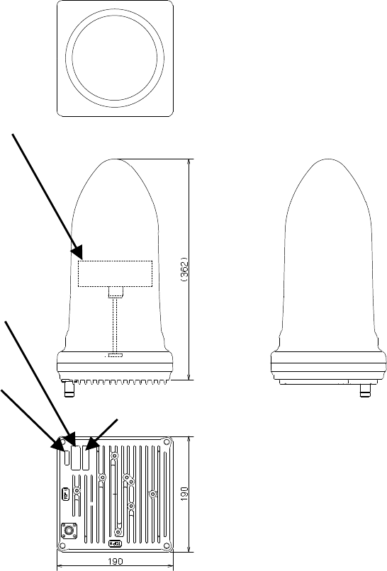
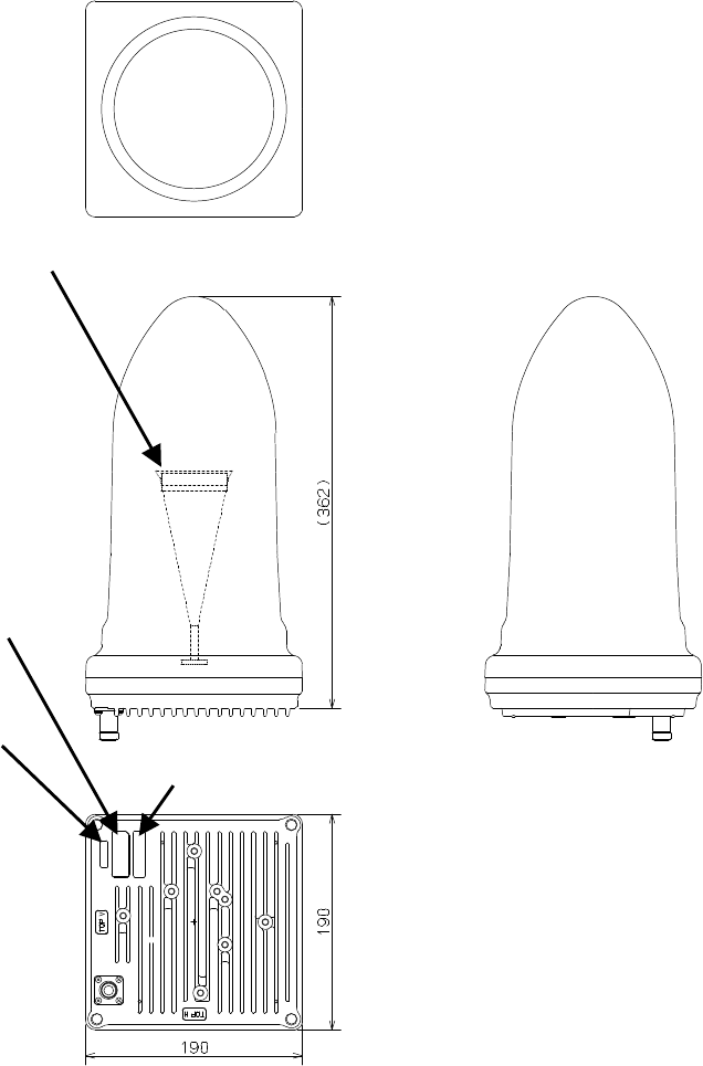
Physical RFU:Dimensions W190XH190XD362(mm) RF Unit (Internal Antenna):Dimensions W190XH190XD61(mm)
Weight 3kg Weight about 2kg
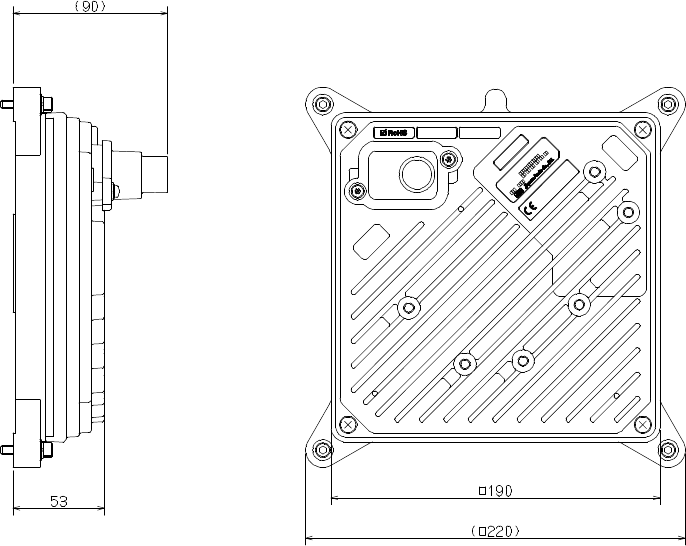
RF Unit (External Antenna):Dimensions W220 XH220XD53(mm)
Weight about 3kg
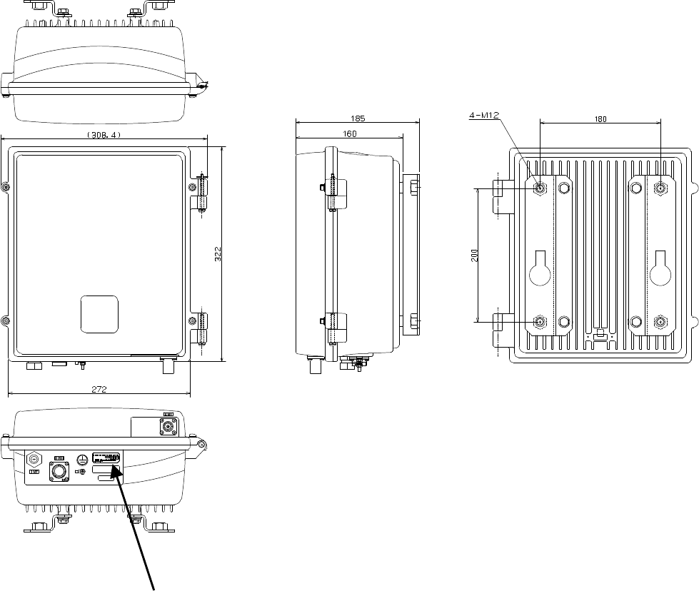
IFU:Dimensions W275XH325XD165(mm) WT Adapter:Dimensions W45XH95XD40(mm)
Weight 8kg Weight about 100g
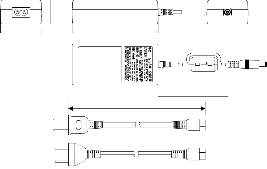
AC Adapter:Dimensions W60XH38XD120(mm) (NBG-317)
W52XH30XD108(mm) (NBG-399R)
Weight about 330g
Temperature -33degree Celsius - +50degree Celsius cold
start at minimum –10degree Celsius ambient
RF Unit: -33degree Celsius - +50degree Celsius cold start at
minimum –10degree Celsius ambient
WT Adapter: -20degree Celsius - +50degree Celsius
AC Adapter: 0degree Celsius - +40degree Celsius
Humidity 20% - 80% non-condensing
2-9
2.2. External Views of the Units
2.2.1. AP-RFU (Omni Antenna)
(in mm)
Figure 2-1 External View of the AP-RFU (Omni Antenna)
(b)
(a)
Omni Antenna
(c)
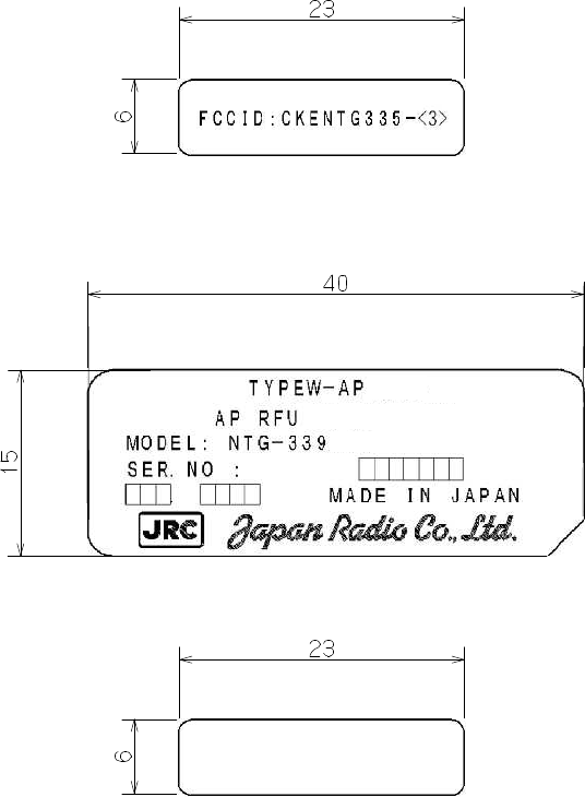
2-10
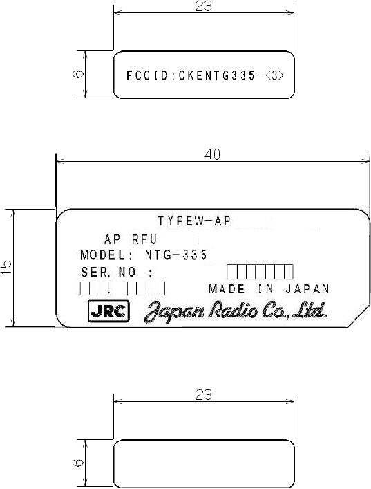
2.2.1.1. AP-RFU (Omni Antenna) Nameplate
Nameplate(a)
Nameplate(b)
Nameplate(c)
Figure 2-2 Nameplate
<1>
L0 : 24.050∼24.549GHz
L1 : 24.549∼24.997GHz
L2 : 24.997∼25.445GHz
H1 : 25.557∼26.005GHz
H2 : 26.005∼26.453GHz
<4>
Blank : non RoHS
R : RoHS
<2>
H : Horizontal Polarization
V : Vertical Polarization
<3>
EL0 : 24.050∼24.549GHz
EL1 : 24.549∼24.997GHz
EL2 : 24.997∼25.445GHz
EH1 : 25.557∼26.005GHz
EH2 : 26.005∼26.453GHz
SER.NO :
MADE IN JAPAN.
TYPEW−AP
<3>
<3>
(Omni<2>)
<1><2><4>
FCCID:CKENTG335−
FCCID:CKENTG335−
768B-NTG339<1>
2-11
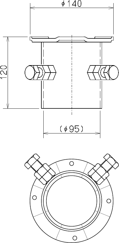
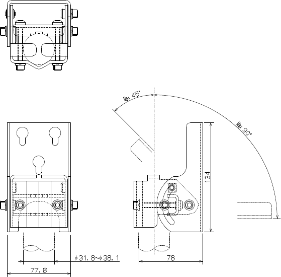
2.2.1.2. AP-RFU (Omni Antenna) Mounting Bracket
(in mm)
Figure 2-3 Mounting Bracket
2-12
2.2.2. AP-RFU (Sectoral-Horn Antenna)
(in mm)
Figure 2-4 External View of the AP-RFU (Sectoral-Horn Antenna)
(b)
(a)
Sectoral-Horn Antenna
(c)
2-13
2.2.2.1. AP-RFU (Sectoral-Horn Antenna) Nameplate
Nameplate(a)
Nameplate(b)
Nameplate(c)
Figure 2-5 Nameplate
<1>
L0 : 24.050∼24.549GHz
L1 : 24.549∼24.997GHz
L2 : 24.997∼25.445GHz
H1 : 25.557∼26.005GHz
H2 : 26.005∼26.453GHz
<4>
Blank : non RoHS
R : RoHS
<2>
H : Horizontal Polarization
V : Vertical Polarization
<3>
EL0 : 24.050∼24.549GHz
EL1 : 24.549∼24.997GHz
EL2 : 24.997∼25.445GHz
EH1 : 25.557∼26.005GHz
EH2 : 26.005∼26.453GHz
SER.NO :
MADE IN JAPAN.
TYPEW−AP
<3>
<3>
(SectralHorn<2>)
<1><2><4>
FCCID:CKENTG335−
FCCID:CKENTG335−
768B-NTG335<1>
2-14
2.2.2.2. AP-RFU (Sectoral-Horn Antenna) Mounting Bracket
(in mm)
Figure 2-6 Mounting Bracket
2-15
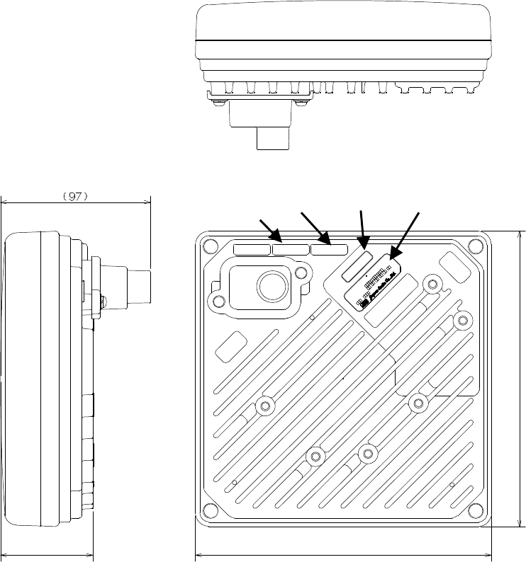
2.2.3. AP-IFU
(in mm)
Figure 2-7 External View of the AP-IFU
(a)
D A T E :
S E R . N O . :
T Y P E W − A P < E L 0 >
2-16
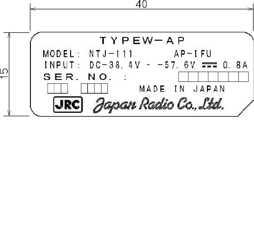
2.2.3.1. AP-IFU Nameplate
Nameplate(a)
(in mm)
Figure 2-8 Nameplate
<1>
Blank : non RoHS
R : RoHS
DATE :
SER.NO.:
INPUT: DC−38.4V
−
−57.6V 0.8A
TYPEW−AP<EL0>
MADE IN JAPAN
<1>
2-17
2.2.4. WT
(in mm)
Figure 2-9 External View of the WT
60
TOP V
TOP H
ETHER
IN P U T :
S ER . NO :
M A C :
.::: : :
MA D E I NJAPA N
DC 2 4 V 0 . 7A
T Y PEW − WT < E L0>
FC CID : CK E N T G33 7 −E L 0
(a)
(b)
(c)
61
1
90
1
90
(d)
2-18
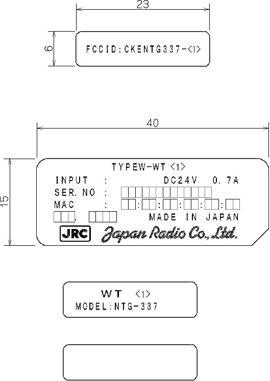
2.2.4.1. WT Nameplate
Nameplate(a)
Nameplate(b)
Nameplate(c)
Nameplate(d)
Figure 2-10 Nameplate
INPUT :
SER.NO :
MAC :
.:::::
MADE IN JAPAN
DC24V 0.7A
TYPEW−WT
FCCID:CKENTG337−
<1>
EL0 : 24.050∼24.549GHz
EL1 : 24.549∼24.997GHz
EL2 : 24.997∼25.445GHz
EH1 : 25.557∼26.005GHz
EH2 : 26.005∼26.453GHz
<3>
U : USA Type AC Plug
E : European Type AC Plug
<2>
L0 : 24.050∼24.549GHz
L1 : 24.549∼24.997GHz
L2 : 24.997∼25.445GHz
H1 : 25.557∼26.005GHz
H2 : 26.005∼26.453GHz
<4>
Blank : non RoHS
R : RoHS
<2><3><4>
<2><3><4>
768B
-
NTG337<2>
2-19
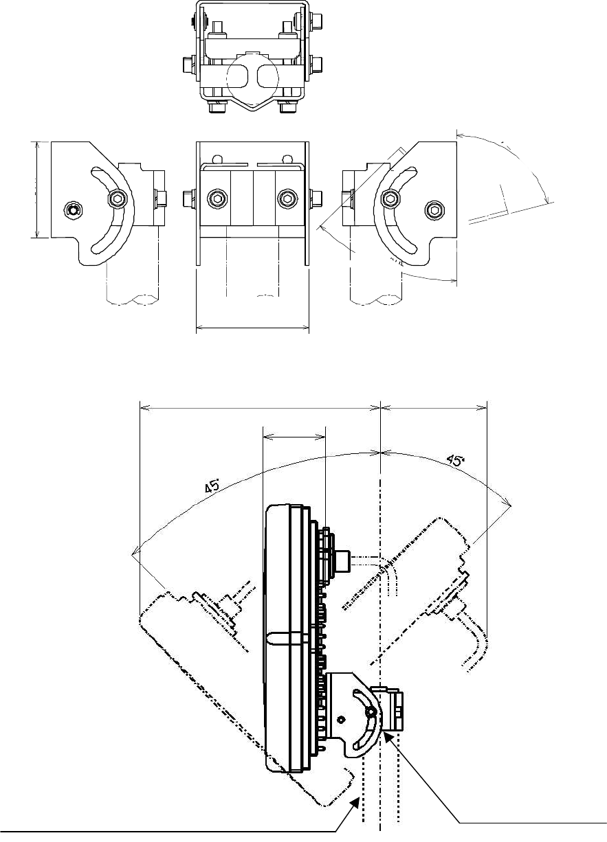
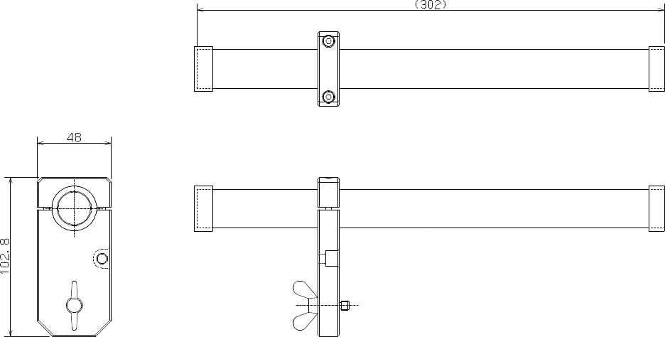
2.2.4.2. WT Mounting Bracket
74
45
°
or less
64
75
°
or less
(in mm)
Figure 2-11 External View of the Outdoor Mounting Brackets for the WT
(240) 150 or more
61
Pole for installation
(Applicable outer diameter : Φ31.8mm to Φ34mm)
Mounting Bracket
(It is possible to install
it only on the point
part in the pole.)
2-20
2.2.5. WT (External Antenna)
Figure 2-12 External View of the WT (External Antenna)
TOP V
TOP H
ETHER
I NP UT:
SER.NO:
MAC :
.:::: :
MADEIN JA PA N
2-21
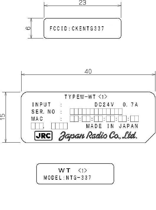
2.2.5.1. WT (External Antenna) Nameplate
Nameplate(a)
Nameplate(b)
Nameplate(c)
Figure 2-13 Nameplate
INPUT :
SER.NO :
MAC :
.:::::
MADE IN JAPAN
DC24V 0.7A
TYPEW−WT
FCCID:CKENTG337−
<1>
EL0 : 24.050∼24.549GHz
EL2 : 24.997∼25.445GHz
<3>
U : USA Type AC Plug
E : European Type AC Plug
<5>
XL0 : 24.050∼24.549GHz
XL2 : 24.997∼25.445GHz
<2>
X0 : 24.050∼24.549GHz
X2 : 24.997∼25.445GHz
<4>
Blank : non RoHS
R : RoHS
<2><3><4>
-<5>
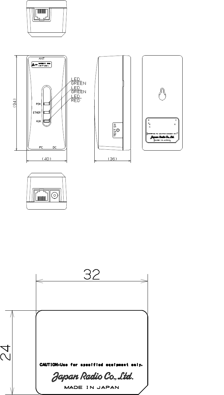
2-22
WT ADAPTER
MODEL NQD−2049
2.2.6. WT Adapter
(in mm)
Figure 2-14 External View of the WT Adapter
2.2.6.1. WT Adapter Nameplate
(in mm)
Figure 2-15 Nameplate
MODEL NQD−2049
WT ADAPTER
<1> <1>
Blank : non RoHS
R : RoHS
2-23
2.2.7. WT AC Adapter
(in mm)
Figure 2-16 External View of the WT AC Adapter
2000
52
30
108
1710
H-7ZCCM0132 (A Type)
H-7ZCCM0135 (C Type)
2-24
2.2.8. Antenna direction adjustment tool
(in mm)
Shape of the scope is subject to change without notice.
Figure 2-17 Antenna direction adjustment tool
3-25
3. AP
3.1. AP-RFU
3.1.1. Overview
The AP-RFU consists of three blocks: Antenna section, RF section and IF section.
3.1.2. Antenna section
The omni-directional antenna (with horizontal directivity of 360°) and the Sectoral-Horn-type antenna
( 90° × 10° directivity) look the same.
3.1.3. RF section
In the RF section, the transmission IF signals are up-converted into 24-26 GHz-band RF signals using
the local signal, which is generated by multiplying the 2.4 GHz synthesized oscillator. The next-stage
BPF eliminates unwanted sideband components. The up-converted 24-26 GHz-band RF signals are
amplified up to the desired level then fed to the antenna via the TDD-Switch and the Waveguide Filter.
The received 24-26 GHz-band RF signals by the antenna are fed in to the LNA via the Waveguide Filter
and the TDD-Switch. The output signals of the LNA are down-converted into IF signals using the local
signal, which is generated by multiplying the 2.4 GHz synthesized oscillator. The BPF is employed to
eliminate the image components (interference).
The TDD Switch selects the transmitting or receiving function. Detection of the transmiting burst at the
IF section turns the switch to the transmiting side.
3.1.4. IF section
In the receiving IF section, the output level to the AP-IFU is adjusted by the automatic gain control (AGC)
function, so that the input level of the AP-IFU does not saturate for the reception of the WT signal which
gives highest receiving level. The SAW filter eliminates the adjacent channel interference.
In the transmitting IF section, the detection of the transmiting burst signal controls the TDD-Switch in the
RF section to turn it to the transmiting side. The SAW filter provides the signal delay for the period of the
burst detection and the TDD-Switch turning time, as well as the elimination of the non-desired signal
component.
The IF section also has the compensation functionality for cable losses between the AP-RFU and
AP-IFU.
3-26
The CPU in the IF section performs the AGC, the cable loss compensation, and the monitoring and
control functionalities.
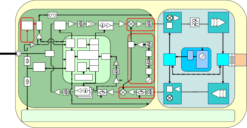
Figure 3-1is a block diagram of the AP-RFU.
to IFU
AP-RFU
WG
BPF
RF
SW
LNA
SW
2.4GHz
Synth
26G:×5
×n
×2
DOWN_CONV
TRSEL(RF)
PA
×2
UP_CONV
FREQ_CNT
IF部
HYB
ASK
MODEM
Temp
CNT D/A
D/A
AGC
×2
1282.5
MHz
ATPC
AGC
213.75
MHz
MAX_HOLD/
AVERAGING A/D
TRCNT
Variable[20dB]
Temp
CNT
RFU
¦
IFU
Cont
Temp Sens
VAR_ATT
[30dB]
CABLE
LOSS
DC+16V
LOGAMP
TMG
Gen
TH
CNT
Obstacle
information
TRSEL(RF)
FREQ_CNT[DATLCLK/LE]
427.5
MHz
SAW_BPF
IF_Freq
1710MHz
SAW_BPF
Horn
Antenna(V/H)
or
Omni
Antenna(V/H)
×3
BPF
SAW
BPF
BPF
BPF
LOGAMP
SAW_BPF
AGC2
RX_LVL
CNT
AUTO ON/OFF
AGC2
RFU-IF
RFU_PS
Serge protection
Coaxal
CABLE
HYB
COMP
Figure 3-1 AP-RFU Block Diagram
3.1.5. Operations and Indications
The AP-RFU does not have any operation or indication panels.
3.1.5.1. Indications
The AP-RFU does not have any LEDs or other status indicators.
3.1.5.2. Switches
The AP-RFU does not have any switches.
3-27
3.1.6. Terminals
3.1.6.1. Omni Antenna
(a) IF terminal connector
Contents Connect the AP-IFU with the coaxial cable.
Shape N-Type Jack for Coaxial
Applicable Connector N-Type Plug for Coaxial
Figure 3-2 Connecting Section of the AP-RFU (Omni Antenna)
3.1.6.2. Sectoral-Horn Antenna
(a) IF terminal connector
Contents Connect the AP-IFU with the coaxial cable.
Shape N-Type Jack for Coaxial
Applicable Connector N-Type Plug for Coaxial
Figure 3-3 Connecting Section of the AP-RFU (Sectoral-Horn Antenna)
TOP H
TOP V
(a)
IF terminal connector
TOP H
TOP V
(a)
IF terminal connector
3-28
3.2. AP-IFU
3.2.1. Overview
AP-IFU consists of three blocks: IF section, digital section and interface section.
3.2.2. IF section
The transmission IF section performs quadrature modulation of 427.5MHz IF frequency according to the
transmission output from the digital modem installed in the WT-ASIC.
In the receiving IF section, the received burst signal level is adjusted by the automatic gain control (AGC)
function of the digital modem. The quadrature demodulator downconverts the received IF signal into the
baseband signal.
The digital section consists of a digital modem, TDD/TDMA framer, wireless MAC processor, and system
controller. These functionalities are equipped in the WT-ASIC.
The digital modem performs modulation and demodulation of transmitting and receiving burst signals.
The interface section has an interface between the AP and the upper unit (100BASE-TX).
The digital section consists of the wireless MAC processor, TDD/TDMA controller, modem and system
controller. The wireless MAC processor converts between the Ethernet frames that the interface section
handles and wireless MAC frames. It also schedules the dynamic slot assignment. The TDD/TDMA
controller performs scrambling, encryption, error correction and other processing. The system controller
performs operating parameter setting, state monitoring, control and testing for the modem, TDD/TDMA
processor, wireless MAC processor and network interface. It also sends and receives maintenance
signals via SNMP. It performs delay control, authentication and other procedures, operating parameter
setting, state monitoring, control and testing for the subordinate WTs over a DMF channel.
The transmission IF section in the IF section performs quadrature modulation for the transmission
baseband signals at 427.5MHz LOC frequency for upconversion to IF signals. It also controls the output
level to the desired level based on the control from the ASIC. The receive IF section equalizes the level of
the reception waves arriving in a wide level range using the automatic gain control (AGC) from the ASIC,
and then downconverts them into baseband signals.
Figure 3-4 is a block diagram of the AP-IFU.
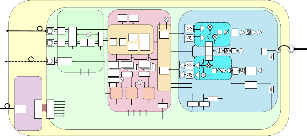
3-29
+5V
Regulator
0/90
HYB ×2
0/0 BAL
UNB
LC_BPF
213.75MHz
LC_LPF +5.0 LC _B PF
+5.0
LC_LPF
digital
ATT
[15dB]
UNB
BAL
-3.3V
+3.3_MOD +3.3_ DE M
+5V
+16V
+16V
to RFU
Regulator
Regulator
0/0
0/90
ASK
MODEM
Interface part
PHY_RST
(FROM_AP-ASIC)
L2SW_RST
(FROM_AP-ASIC)
TRANS
LAYER2
SW
RJ-45
RJ-45
TRANS
PHY
TRANS TRANS
25MHz
RS-232C
driver/receiver
4pin
MOJUR A
MAC
TDD
AP-ASIC
Digital part
U-CPU
15.625
MHz
Reset
IC TMP
SENS
20MHz
LVL CNT_T/R
+16V(RFU)
+3.3V(for AP/MODEM-ASIC,IF)
+2.5V(for AP-ASIC)
+1.8V(for U-CPU,D-CPU,L2SW)
+1.5V(for MODEM-ASIC)
+5V(for ANALOG ⇒3.3V)
CABLELOSSATT(ATT)
AP-IFU
+2.5V
+3.3V
+1.8V
+3.3V
MOD
DEM
MODEM
ASIC
S-CPU
RTC
FROM
64M
serial
EEPROM
32×8
SDRAM
8M×16
D-CPU
FROM
16M
SDRAM
8M×16
FROM
16M
SDRAM
8M×16
27.83MH z
TX
RX
D-FIFO
D-FIFO
EDC
2.5MHz
S_RST
[FROM_AP-ASIC] D_RST
[FROM_AP-ASIC] U_RST
[FROM_AP-ASIC]
MODEM-ASIC_RST
(FROM_S-CPU)
+1.8V
+5V
Regulator
+3.3_ASIC
ANALOG
+1.5V
TDD_SELECT
IFU-MAC
(to PC)
DC-48V
Pow
supply
conn.
Power
supply
connector
100BASE-
TX
Pow
supply
conn.
IF part
SW
MOD_I/Q
(BAL)
DEM_I/Q
(UNBAL)
to RFU
Serge protection
Serge protection
Serge protection
IFU-PS
Coaxal
CABLE
Figure 3-4 AP-IFU Block Diagram
3-30
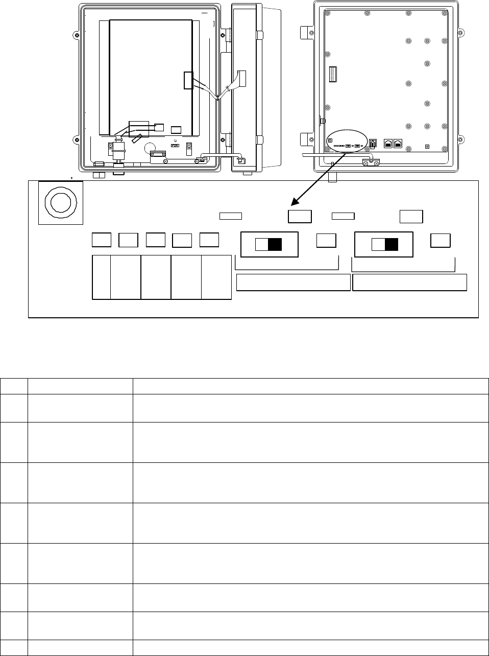
3.2.3. Operations and Indications
3.2.3.1. Indications
Figure 3-5 AP-IFU Operation and Indication Panel
Table 3-1 AP-IFU Indications
LED State indication
a POWER Lit green: Power on
Extinguished: Power off
b ETHER 1 Lit green: ETHER link established
Flashing green: ETHER signal sent or received
Extinguished: ETHER link down (See Table 3-3, 4)
c ETHER 2 Lit green: ETHER link established
Flashing green: ETHER signal sent or received
Extinguished: ETHER link down (See Table 3-3, 5)
d IFU STATE Lit red: IFU alarm (See Table 3-3, 2)
Flashing green: Normal (CPU running)
Flashing orange: During initialization
e RFU ALARM Lit red: RFU alarm (Cause: RFU failure (See Table 3-3, 1) or
communication error between the IFU and RFU (See Table 3-3, 3))
Extinguished: RFU alarm cleared
f ETHER1 AUTO Lit green: AUTO (ETHER1 AUTO switch set to AUTO)
Extinguished: 100BASE full duplex
g ETHER2 AUTO Lit green: AUTO
Extinguished: 100BASE full duplex
h RST Unit reset switch
制御盤LED部拡大図
26G
-
2
-
AP
-
PWR
26G-2-AP-CNT
POWER
ETHER
1
ETHER
2
IFU
STATE
RFU
ALARM
AUTO 100
FULL AUTO 100
FULL
ETHER1 AUTO ETHER2 AUTO
① ② ③ ④ ⑤ ⑥ ⑦
⑧
b
c
d
e
f
g
a
h

3-31
Table 3-2 AP-IFU Controls
Switch Description
1 ETHER1 AUTO
Sets the ETHER1 interface (100BASE full duplex/AUTO).
After changing the switch setting, you have to reboot the unit (power off
and back on) to enable the new setting.
AUTO: AUTO
100FULL: 100BASE full duplex (factory setting)
2 ETHER2 AUTO
Sets the ETHER2 interface (100BASE full duplex/AUTO).
After changing the switch setting, you have to reboot the unit (power off
and back on) to enable the new setting.
AUTO: AUTO
100FULL: 100BASE full duplex (factory setting)
Table 3-3 Alarm Issuance and Clear Conditions
Item Initial state Issued when: Cleared when:
The RFU-CPU detects LOCALM
or TRSELALM three times each
for more than 10msec.
The RFU-CPU detects
no LOCALM or
TRSELALM three
times each for more
than 10msec.
LOCALM (local oscillator alarm)
occurs if the local oscillator lost
synchronization.
Synchronization is
recovered.
TRSELALM
(transmission/reception
switchover SW failure) occurs if
the transmission state continues
for more than 1sec.
Only by a reset.
1 RFU failure Cleared
IFU-CPU detects a RFU-IFU
communication error (monitoring
response).
IFU-CPU is cleared by
a single RFU-IFU
communication
(monitoring response).
Communication error among the
S-CPU, D-CPU and U-CPU.
No response to polling for 3sec
Cleared by a single
response.
2 IFU failure
Cleared
L2SW setting failure
If setting failed four times (once
for transmission and 3 times for
retransmission)
No recovery
3 Communication
error between
RFU and IFU
Cleared The S-CPU detects a
S-RFU-CPU communication
error.
No response to polling four
times (once for transmission
and 3 times for retransmission)
Cleared by a single
response.
4 ETHER 1 link
down Issued PHY link down 3 times each for
100msec. Recovered from PHY
link down 3 times each
for 100msec.
5 ETHER 2 link
down Issued PHY link down 3 times each for
100msec. Recovered from PHY
link down 3 times each
for 100msec.
3-32
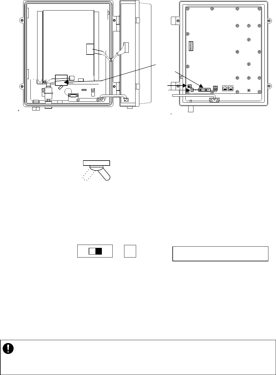
3.2.3.2. Switches
Figure 3-6 Switches on the AP-IFU
(a) Power switch
This is the switch to supply power to the AP-IFU and AP-RFU.
(b) ETHER1/ETHER2 switch
This is the switch to set AUTO or 100FULL.
(The shape of the switch may be changed.)
(c) RST switch
This is the switch to reset the unit.
(d) POWER LED
When on : Lit green
When off: Extinguished
①
②
③
④
a
b
c
d
Factory setting: 100FULL
ETHER AUTO LED
AUTO: Lit green
100FULL: Extinguished
100
FULL
AUTO
ETHER1 AUTO
ONOFF
・ After changing the switch setting, you have to reboot the unit (power off and back on) to
enable the new setting.
3-33
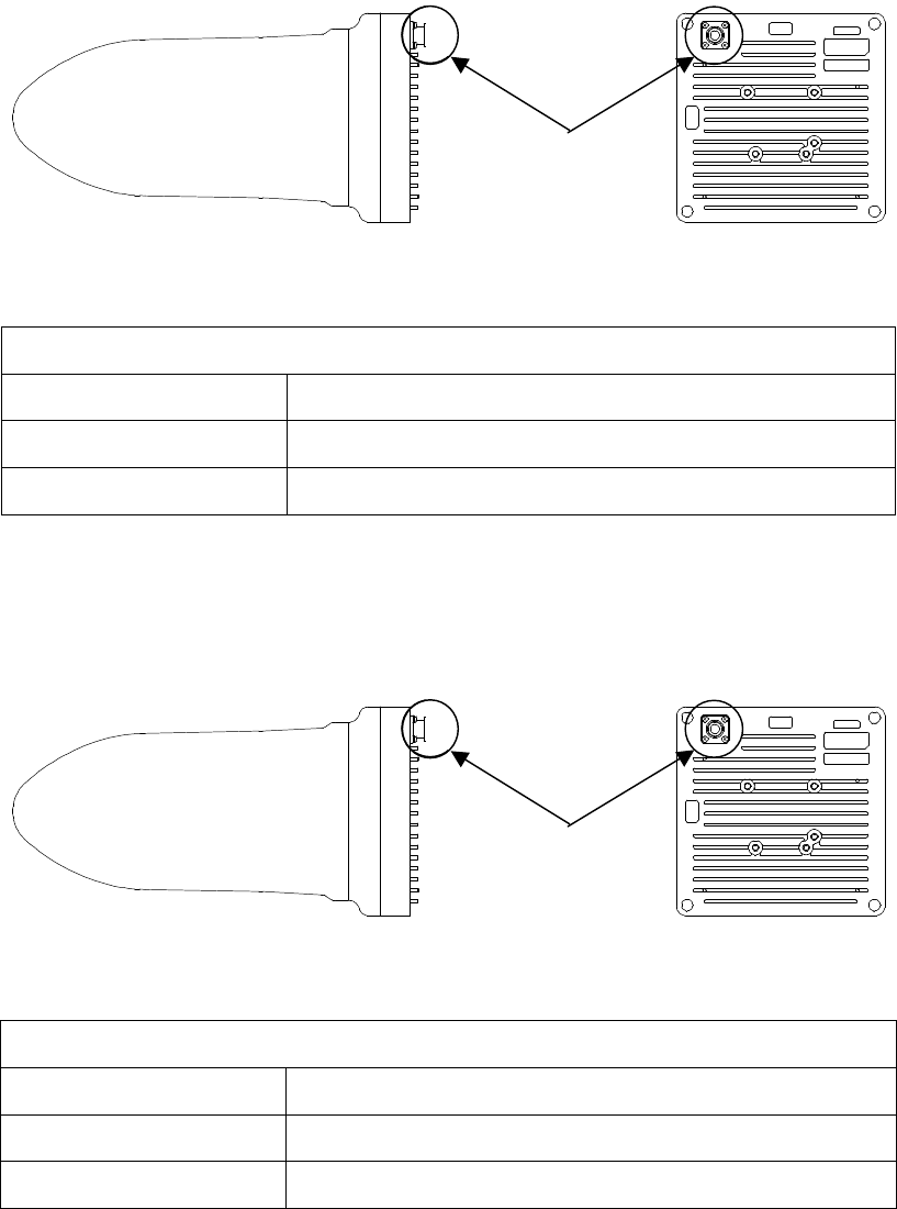
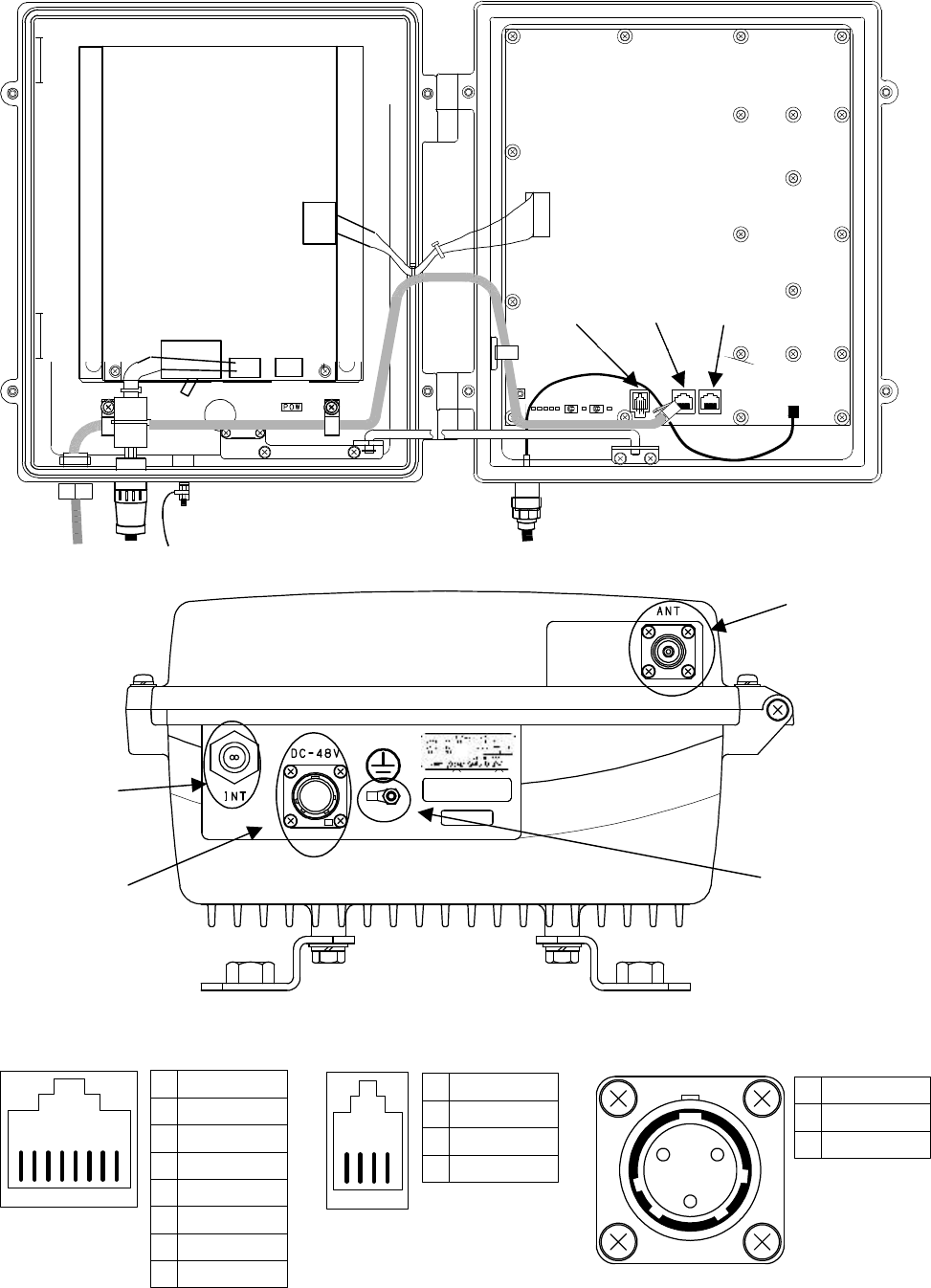
3.2.3.3. Terminals
Figure 3-7 Connecting Section of the AP-IFU (Open View)
Figure 3-8 Connecting Section of the AP-IFU (Bottom View)
Figure 3-9 (a),(b)Ethernet connector
Figure 3-10 (c)MNT connector
Figure 3-11 (f)Power cable connector
1 2
3
8 7 6 5 4 3 2 1 4 3 2 1
1
2
3
4
TXD
RXD
NU
GND
1
2
3
GND
DC-48V
NU
1
2
3
4
5
6
7
8
TXD+
TXD-
RXD+
RXD-
GND
NU
NU
NU
e
d
f
g
SER.NO.
IN PUT :
DA TE :
MADE IN JAPAN
TYPE W−AP<EL0>
DC− 48V 0.8A
a b
c

3-34
(a) ETHER1 connector
Connect the outside network Contents
The user signal distributed by internal SW-HUB,and output to ETHER1 and
ETHER2. ETHER1 is used usually.
Interface 100BASE-Tx
Connector shape RJ-45
Pin assign See Figure 3-9
(b) ETHER2 connector
Connect the outside network Contents
The user signal distributed by internal SW-HUB,and output to ETHER1 and
ETHER2. ETHER1 is used usually.
Interface 100BASE-Tx
Shape RJ-45
Pin assign See Figure 3-9
(c) MNT(maintenance) connector
Contents Connect the Local management tool
Interface Serial
Shape RJ-22
Pin assign See Figure 3-10
(d) ANT terminal connector
Contents Connect the AP-IFU with the coaxial cable.
Shape N-Type Jack for Coaxial
Applicable Connector N-Type Plug for Coaxial
(e) Ethernet cable inlet
Contents Insert the Ethernet cable into the rubber bushing.
Applicable outer diameter
Φ5.5mm or less
(f) FG terminal
Contents Connect the ground wire.
Applicable Cable Ground wire more than 1.5□mm
Applicable terminal FG terminal M4nut.
(g) Power cable connector
Contents Connect the power cable.
Pin assign See Figure 3-11
Name NRW-203-RM-ULCSATUV (Nanaboshi Electric MFG Co.,LTD.)
Applicable Connector
name
NRW-203-PF8-ULCSAUV (Nanaboshi Electric MFG Co.,LTD.)
(This connector is supplied with AP-IFU.)
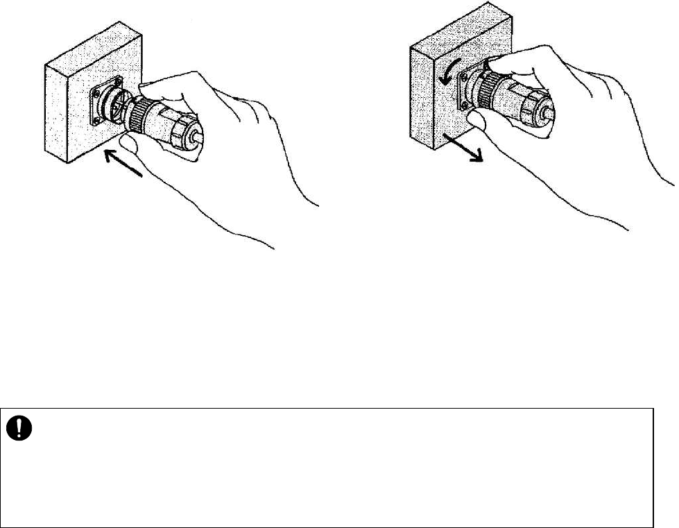
3-35
How to install and remove the power cable connector
To install:
Align the plug and receptacle guides,
and push in the connector straight.
To remove:
Turn the connector counterclockwise 45
degrees and pull it out straight.
・ Power cable terminal (g): The DC -48V power supply voltage for AP-
IFU shall be SELV or
TNV-1 depending on the network environment (0 or 1) acc. to IEC62102.
・ Ethernet cable inlet (e):The Equipment for connection to AP-IFU Ethernet-
interface
(RJ-45) shall be appropriate to connect to TNV-1 circuits.
4-36
4. WT
4.1. WT
4.1.1. Overview
The WT consists of the antenna section, RF section, IF section, digital section, interface section
and power supply.
4.1.2. Antenna section
Uses a Triplate planar antennas to make the antenna compact and to provide a high gain. When
you use an option, you can install a external antenna.
4.1.3. RF section
In the RF section, the transmission IF signals are up-converted into 24-26 GHz-band RF signals
using the local signal, which is generated by multiplying the 2.4 GHz synthesized oscillator. The
next-stage BPF eliminates unwanted sideband components. The up-converted 24-26 GHz-band
RF signals are amplified up to the desired level then fed to the antenna via the TDD-Switch and
the Waveguide Filter.
The received 24-26 GHz-band RF signals by the antenna are fed in to the LNA via the Waveguide
Filter and the TDD-Switch. The output signals of the LNA are down-converted into IF signals
using the local signal, which is generated by multiplying the 2.4 GHz synthesized oscillator. The
BPF is employed to eliminate the image components (interference).
The TDD Switch selects the transmitting or receiving function under the control of TDD/TDMA
framer installed in the WT-ASIC.
4.1.4. IF section
The transmission IF section performs quadrature modulation of 427.5MHz IF frequency according
to the transmission output from the digital modem installed in the WT-ASIC. The SAW filter in
the next stage eliminates undesired out-of-band signals. The output level of the transmission IF
section is adjusted by the automatic transmission gain control (ATPC) function of the digital
modem.
.
In the receiving IF section, the SAW filter eliminates the adjacent channel interference. The
received burst signal level is adjusted by the automatic gain control (AGC) function of the digital
modem. The quadrature demodulator downconverts the received IF signal into the baseband
signal.
4-37
4.1.5. Digital section
The digital section consists of a digital modem, TDD/TDMA framer, wireless MAC processor, and
system controller. These functionalities are equipped in the WT-ASIC.
The digital modem performs modulation and demodulation of transmitting and receiving burst
signals.
The TDD/TDMA framer constructs and deconstructs radio burst frames. It alse performs
scrambling, encryption, and error correction functionalities.
The wireless MAC processor converts between the Ethernet frames and the wireless MAC
frames in the radio channel.
The system controller performs operating parameter setting, state monitoring, control and testing
for the entire unit. It also communicates with the AP processer via the DMF channel.
4.1.6. Interface section
The interface section provides the physical interrfaces of Ethernet for user interface and serial
interface for the receiving level measurement terminal. It has a lightning surge protector to
protect the unit against external surges.
4.1.7. Power supply
The power supply section generates various voltages used within the unit from +24V input power.
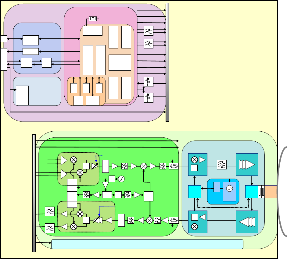
4-38
Figure 4-1 is a block diagram of the WT.
Interface part
Trans
Serge protection
PHY
RJ45
RS-232
DRV/REC
4P_MJ
LED DRV
MJ
MJ
MOD_I/Q(BAL)
DEM_I/Q(UNB)
Power supply part
(digital)
DC/DC
CONV
+3.3V_D(DIGITAL)
+3.3V_A(ANALOG)
+1.5V(for ASIC)
AGC(Analog)
TRSEL(RF)
X'TAL
MAC TDD
MOD
DEM
CPU
ASIC
ATPC(Analog)
DC+24V
AGC(Digital)
ATPC(Digital)
TRSEL(IF)
t
o
I
F
p
a
r
t
D/A
Conv
D/A
Conv
PLL
20MHz/80MHz
Signal processing part
FRASH
ROM
TEMP
SENS
PON
RST EEP
ROM SD
RAM
OFFSET_CNT
FREQ_CNT(RF)
Antenna
WG
BPF
RF
SW
LNA
SW
2.4GHz
Synth
26G:×5
×n
×2
DOWN_CONV
TRSEL(RF)
PA
×2
UP_CONV
FREQ_CNT
t
o
S
i
g
n
a
l
p
r
o
c
e
s
s
i
n
g
p
a
r
t
0/90
0/90
HYB
×2
0/0
213.75MHz
SW TRSEL(IF)
DEM_I/Q
AGC(Analog)
UNB
BAL
SAW_BPF
DEM_IC
AGC(Digital)
0/0
WT-IF
MOD_IC
ATPC(Analog)
MOD_I/Q
×3 HYB
427.5MHz 1282.5MHz
IF_Freq
1710MHz
TRSEL(RF)
FREQ_CNT[CLK/DAT/LE]
BAL
UNB
SAW_BPF
ATPC(Digital)
HYB
Dielectric
_BPF
IRF
IF_Freq
1710MHz
SAW_BPF
LC_BPF
WT-MAC
WT_PS
WT
Figure 4-1 WT Block Diagram
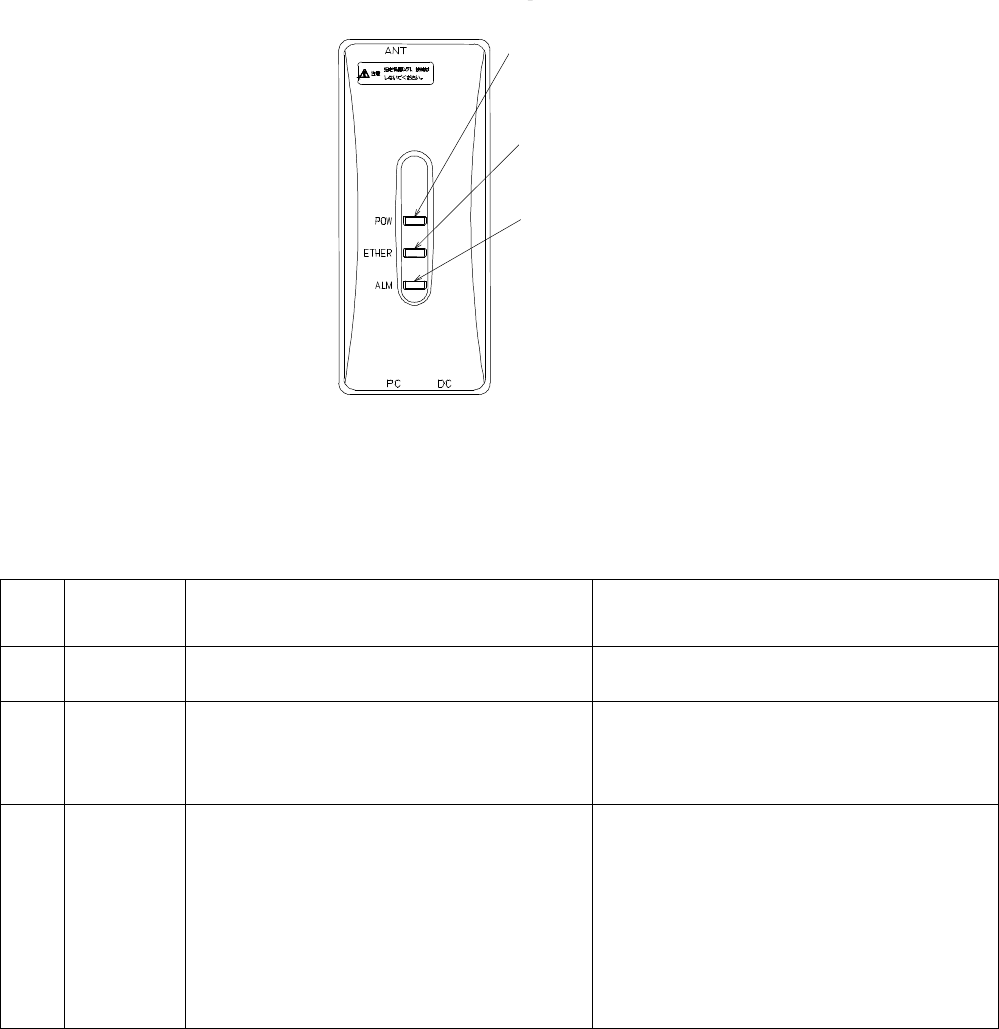
4-39
4.1.8. Operations and Indications
4.1.8.1. Indications
(1) Indications
The indications on the WT adapter allows you to check the state of the WT.
Table 4-1 Indications on the WT Adapter
LED Indication (Point to Multipoint System) Indication (Point to Point System)
a POW -Lit green: Power on.
-Extinguished: Power off. -Lit green: Power on.
-Extinguished: Power off.
b ETHER -Lit green: ETHER link established.
-Flashing green: Transmission or
reception on the ETHER port.
-Extinguished: ETHER link down.
-Lit green: ETHER link established.
-Flashing green: Transmission or
reception on the ETHER port.
-Extinguished: ETHER link down.
c ALM -Lit red: Wireless synchronization lost.
-Flashing red:
/Flashing red for 500msec: Wireless
synchronization established (during
authentication).
/Flashing red for 1 sec: VID use halted
-Extinguished: Wireless
synchronization established (after
authentication)
-Lit red: Wireless synchronization lost.
-Flashing red: Flashing red for
500msec: Wireless synchronization
established (during authentication).
-Extinguished: Wireless
synchronization established (after
authentication)
Figure 4-2 Indications on the WT Adapter
a
b
c

4-40
(2) State transition
The table below shows how each LED changes its state after the power is turned on until the unit
becomes operable.
Table 4-2 LED State Transition when the Power is Turned On (Point to Multipoint system)
Immediately
after the power
is turned on
Several
seconds
after the
power is
turned on
Radio
synchronizati
on lost
Authenticating
after radio
synchronization
is reestablished
Operating
after
authenticatio
n is finished
Remarks
a
POW Lit Lit Lit Lit Lit
b
ETHER Extinguished
(Extinguished)
Lit
(Lit) Extinguished
(Lit/Flashing)
Extinguished
(Lit/Flashing) Extinguished
(Lit/Flashing)
The state
within
parentheses
is that when a
PC is
connected.
c
ALM Extinguished Lit Lit Flashing* Extinguished
*Flashing for 500msec. (On for 500msec. and off for 500msec.)
(3) Lighting conditions
The table below shows when the ALM LED lights.
Table 4-3 Lighting Conditions of the ALM LED in the Out-of-Service State
(Point to Mulitipoint system)
Out-of-service state
Operation state
Out of service Cleared
During
authentication ALM LED=Extinguished ALM LED=Extinguished
During operation ALM LED=Flashing* ALM LED=Extinguished
Carrier off ALM LED=Extinguished ALM LED=Extinguished
*Flashing for one second (On for one second and off for one second)
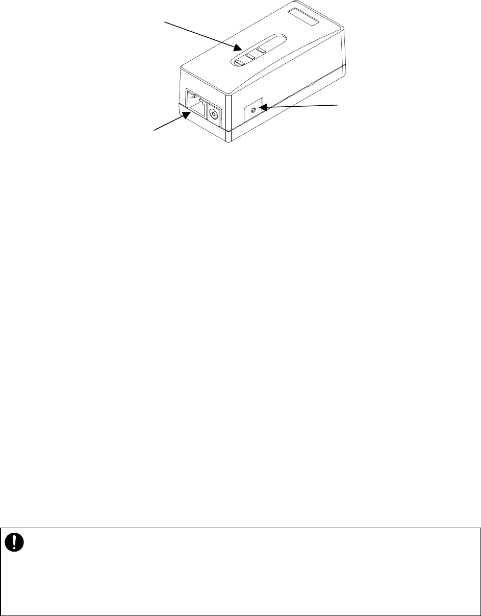
4-41
4.1.8.2. Switches
Figure 4-3 Switches on the WT Adapter
(a) [TEST SW] switch
This is the switch to check for any disconnection on the Ethernet cable connecting the
WT and WT adapter.
The connection of the ETHER signal line (4) in the Ethernet cable (8) can be confirmed.
If you turn on this switch, the Ethernet signal is looped back to the WT and not output to
the PC port.
How to check for a disconnection:
• connected to cable between WT and WT adapter, and turns on the power supply with
the AC adapter.
• Unplug the cable from the PC port of the WT adapter.
• Make sure that the ETHER LED lights.
• Hold down the TEST SW switch.
• (The Ethernet signal from the WT is looped backed to the WT via the WT adapter.)
• The connection is normal if the ETHER LED lights green.
• The four Ethernet signal lines have a disconnection or wrong wiring if the ETHER LED
remains extinguished.
・ The TEST SW cannot identify a wrong connection for the
straight/cross cable. When
connecting a connector, make the correct connection for the straight or cross cable.
If you turn on this switch by mistake, the Ethernet signal is looped back to the WT and not
output to the PC port.
Test SW
ETHER LED
PC port
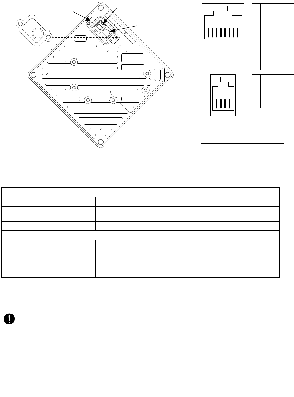
4-42
4.1.8.3. Terminals
4.1.8.3.1. WT
Figure 4-4 Connecting Section of the WT
(a) ETHER port
This is the port to connect the WT to the WT adapter. Use a straight cable between the
WT and WT adapter.
Connected cable between WT and WT adapte
Cable type Ethernet cable for outdoor,straight
Range of applicable outer
diameter φ5.0 mm∼5.7mm
Cable length 50m(max)
Connector
Shape RJ-45
Pin assign ・ Ethernet signal (MDI specification)
・ An Ethernet cable has eight signal lines. Four lines are used to
carry Ethernet signals. The remaining four lines are used as
power lines and LED control lines.
(b) Industrial port
This is the industrial port.
Shape: RJ-22
Use a T20 torx driver t
o
open interface cover
4 3 2 1
1
2
3
4
TXD
RXD
NU
GND
②
8 7 6 5 4 3 2 1
1
2
3
4
5
6
7
8
TXD+
TXD-
RXD+
LED1
LED2
RXD-
+24V _IN
GND
①
a
b
ETHER
Small Lid a
b
Small Window
・
The cable connecting between the WT and WT adapter carries 24 VDC for the WT in
addition to Ethernet signals. Before unplugging the cable connecting between the WT and
WT adapter, make sure to
unplug the DC jack of the WT adapter to turn the power off.
Otherwise, the unit may be damaged.
・
The cable connecting the WT and WT adapter is a straight cable. Wrong connection may
damage the unit.
・ When closing the small window, make sure that the rubber p
acking of the small window is
free from any foreign matter.
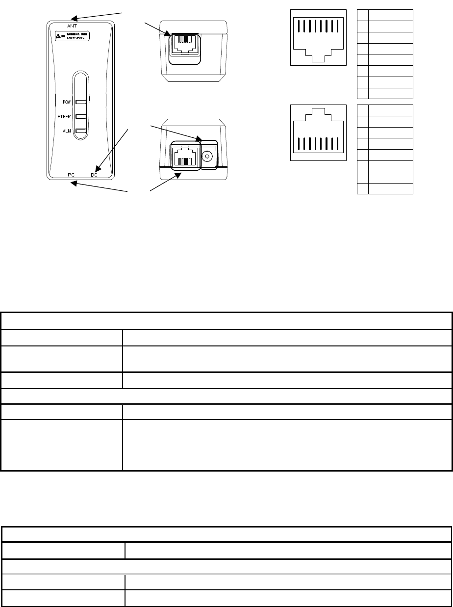
4-43
4.1.8.3.2. WT Adapter
Figure 4-5 Connecting Section of the WT Adapter
(a) ANT port: (Connector type: RJ-45)
This is the port to connect the WT to the WT adapter. Use a straight cable between the
WT and WT adapter.
Connected cable between WT and WT adapte
Cable type Ethernet cable for outdoor,straight
Range of applicable outer
diameter φ5.0 mm∼5.7mm
Cable length 50m(max)
Connector
Shape RJ-45
Pin assign ・ Ethernet signal (MDI―X specification)
・ An Ethernet cable has eight signal lines. Four lines are used to carry
Ethernet signals. The remaining four lines are used as power lines
and LED control lines.
(b) PC port: (Connector type: RJ-45)
This is the port to connect the communication terminal.
(c) DC jack: (+24VDC power supply)
Connect the AC adapter that comes with the WT.
Interface
Interface 10BASE-T/100BASE-TX
Connector
Shape RJ-45
Pin assign Ethernet signal(MDI-X)
Top view
Bottom view
a
c
b
b
8 7 6 5 4 3 2 1
1
2
3
4
5
6
7
8
RXD+
RXD-
TXD+
NU
NU
TXD-
NU
NU
1
2
3
4
5
6
7
8
RXD+
RXD-
TXD+
LED1
LED2
TXD-
+24V _OUT
GND
a1 2 3 4 5 6 7 8

4-44
・
Never connect a communication terminal to the ANT port of the WT adapter. Doing so may
damage your personal computer.
・ The cable connecting between the WT and WT adapter carries 24 VDC f
or the WT in
addition to Ethernet signals. Before unplugging the cable connecting between the WT and
WT adapter, make sure to unplug the DC jack of the WT adapter to turn the power off.
Otherwise, the unit may be damaged.
・ The cable connecting the WT and WT
adapter is a straight cable. Wrong connection may
damage the unit.
・ PC port: (Connector type: RJ-45 (b)
)The Equipment for connection to WT adapter
PC-interface(RJ-45) shall be appropriate to connect to TNV-1 circuits.
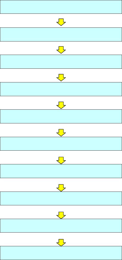
5-45
5. CONSTRUCTING A POINT-TO-MULTIPOINT SYSTEM
(AP)
5.1. Overview
Installing the AP-RFU and AP-IFU
Adjusting the Direction of the AP-RFU
Connecting a Cable between AP-RFU and AP-IFU
Connecting Cables from the AP-IFU to external
The confirmation of AP-IFU
Waterproofing Connectors
Connecting the AP Local Management Tool
Configure the AP parameters
Check sheet of AP Installation
Finish
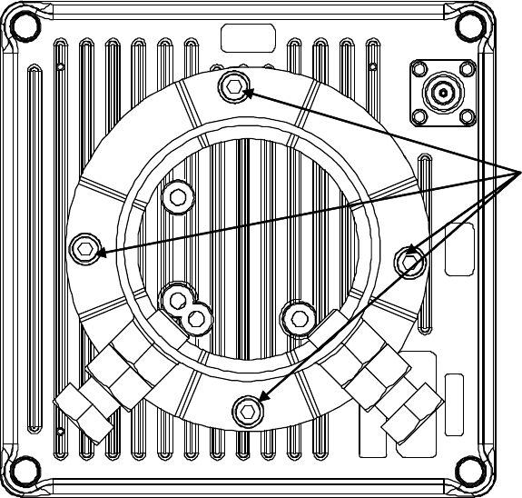
5-46
5.2. Installing the AP-RFU and AP-IFU
5.2.1. Installing the AP-RFU (Omni Antenna)
Secure the AP-RFU (omni antenna) to a pole using the bolts (a), as shown in Figure 5-1.
(1) As shown in Figure 5-1, install the AP mounting bracket on the AP-RFU and tighten
the bolts (a).
a
Figure 5-1 Installing the Mounting Bracket on the AP-RFU (Omni Antenna)
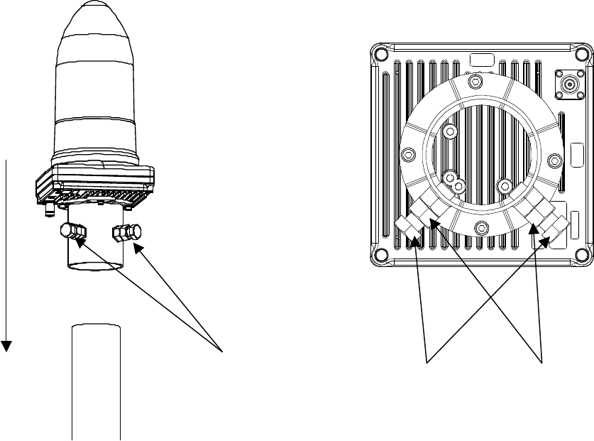
5-47
(2) As shown in Figure 5-2, loosen the bolts and nuts (b) and (c) for the AP mounting
bracket and install the bracket on the pole. Next, tighten the bolts (b) and tighten the
nuts (c) while making sure that the bolts (b) stay in place.
Figure 5-2 Installing the AP-RFU (Omni Antenna)
(b),(c)
(c) (b)
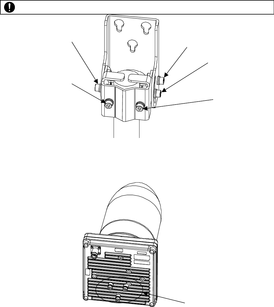
5-48
5.2.2. Installing the AP-RFU (Sectoral-Horn Antenna)
The mounting braket are attached AP-RFU.
(1) As shown in Figure 5-3, loosen the bolts (a), (b), and (c) and install the AP-RFU mounting
bracket on the pole. Next, tighten the bolts (a), (b), and (c). (Recommended tightening torque:
8.5 N-m)
Figure 5-3 Installing the AP-RFU Mounting Bracket on the Pole
(2) As shown in Figure 5-4, finger-tighten the bolts (f) in the threaded holes on the rear of the
AP-RFU.
Figure 5-4 Finger-tightening the Mounting Bolts to the AP-RFU
(f)
(a)
(b)
(c)
(d)
(e)
Applicable pole diameter: From 31.8mm to 38.1mm
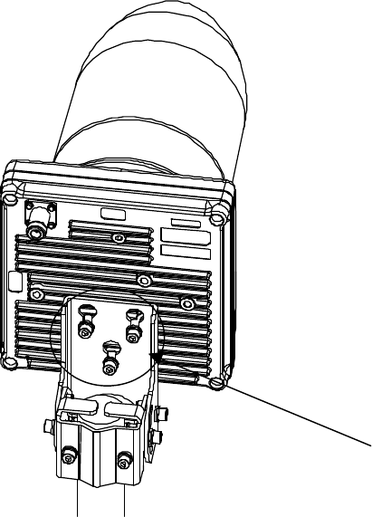
5-49
(3) As shown in Figure 5-5, align the AP-RFU with the openings in the AP-RFU mounting
bracket and tighten the bolts (f). (Recommended tightening torque: 8.5N-m)
Figure 5-5 Installing the AP-RFU on the Mounting Bracket
(f)
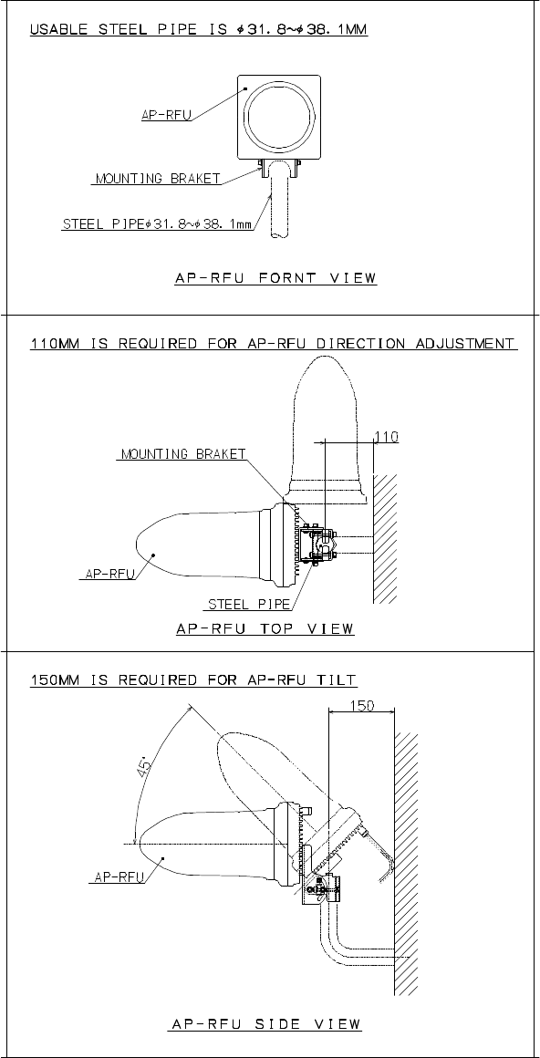
5-50
A builder prepares a steel pipe by the installation place (a wall, a pole or etc.), and it install.
The required space of installation is shown below.
Figure 5-6 the required space of installation
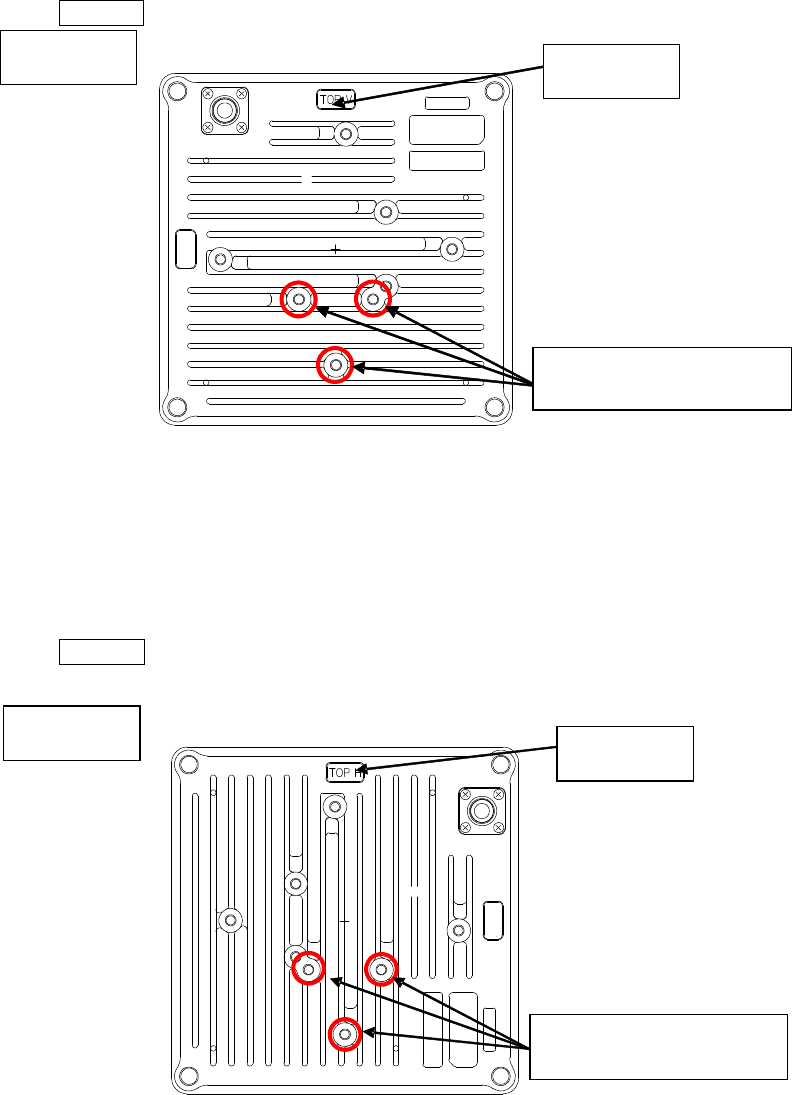
5-51
5.2.3. Setting AP-RFU(Sectoral-Horn Antenna)for Vertical or Horizontal
Polarization
(1) NTG-335<1><2>V
The NTG-335<1><2>V device is used only for the vertical polarization plane. Install it with
the TOP V marking at the top.
Figure 5-7 Vertical Polarization
(2) NTG-335<1><2>H
The NTG-335<1><2>H device is used only for the horizontal polarization plane. Install it with
the TOP H marking at the top.
Figure 5-8 Horizontal Polarization
Horizontal
TOP H
Install the AP mounting
bracket here.
Vertical
Install the AP mounting
bracket here.
TOP V
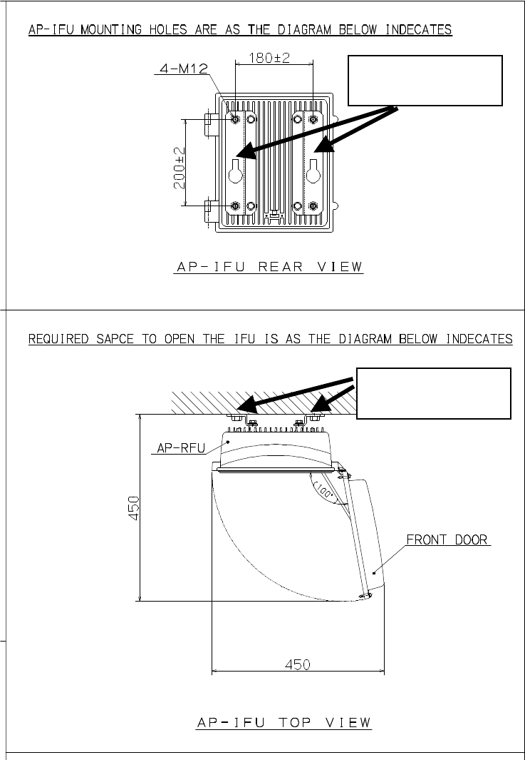
5-52
5.2.4. installing the AP-IFU
5.2.4.1. Installing the AP-IFU
The mounting braket are attached AP-IFU.
A builder prepares a fixing braket by the installation place (a wall, a pole or etc.), and it install.
The required space of installation is shown below.
Figure 5-9 The required space of installation
mounting braket
mounting braket
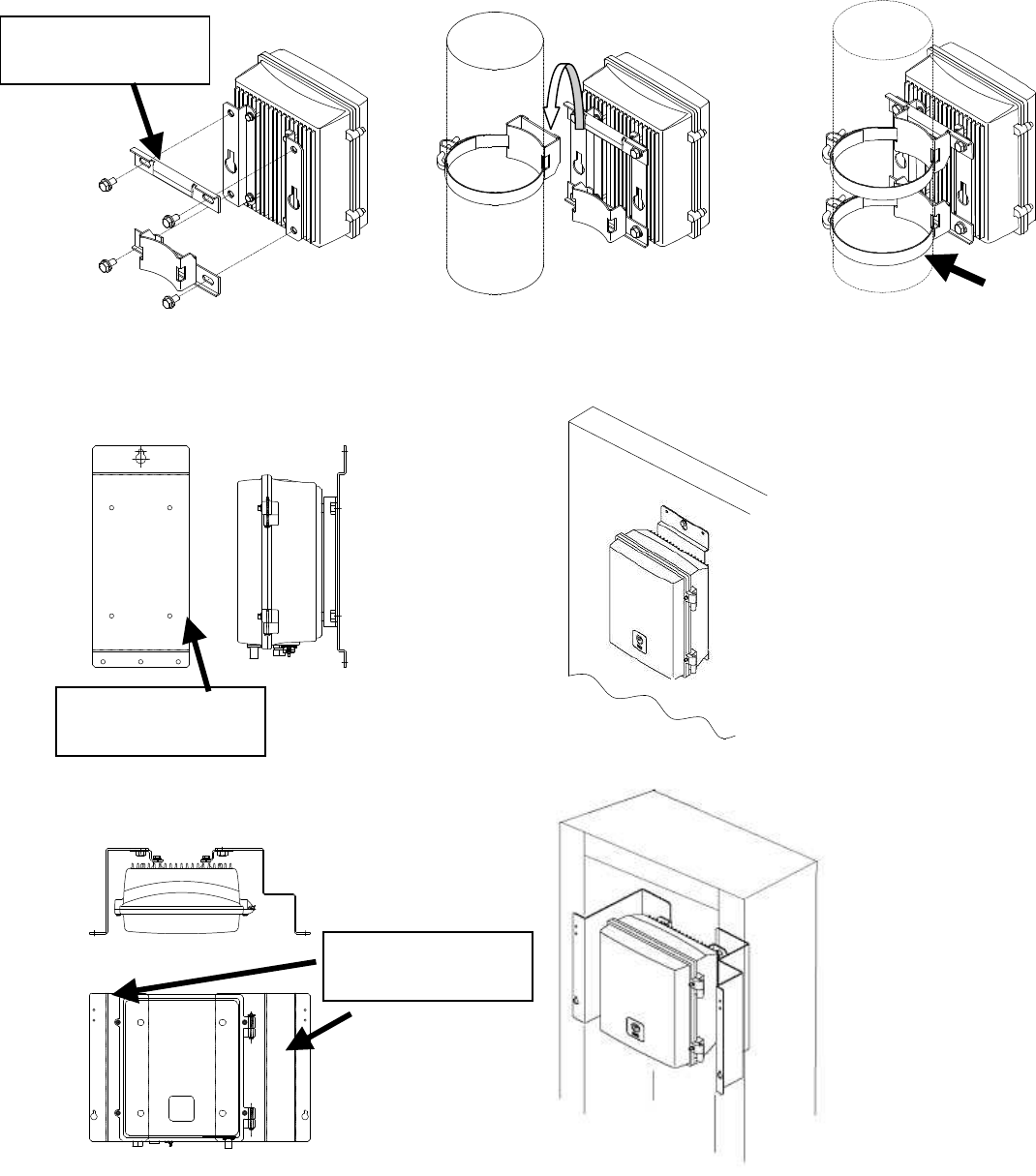
5-53
5.2.4.2. Example of Installing the AP-IFU
(1) On a Utility Pole
Figure 5-10 Installing the AP-IFU on a Utility Pole
(2) Indoor Installation
Figure 5-11 Indoor Installation
(3) 19-inch Rack
Figure 5-12 Installing the AP-IFU on a 19-inch Rack
fixing braket
fixing braket
fixing braket
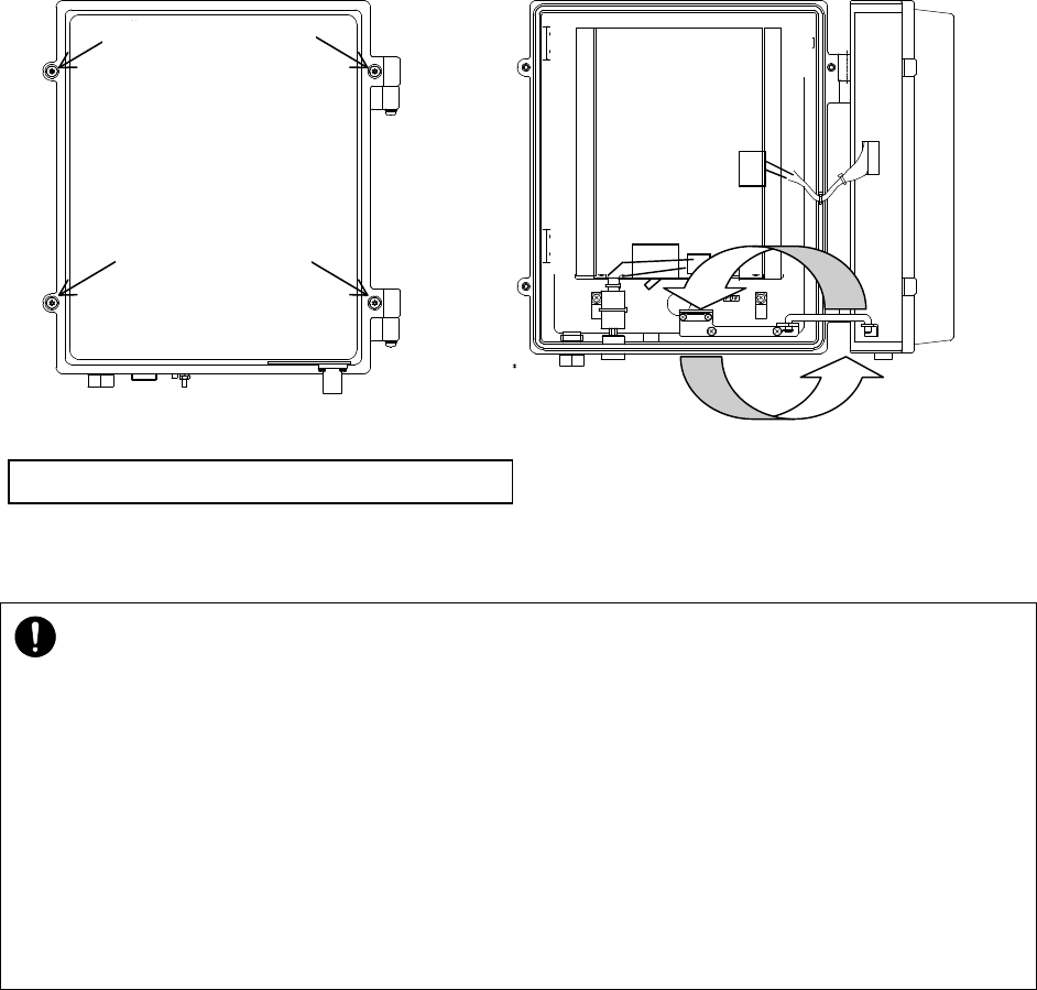
5-54
5.2.4.3. Opening and Closing the AP-IFU Cover
To open the cover:
(1) Loosen the special screws (a) to (d) to open the cover as shown in Figure 5-13.
(2) Keep the cover stay open using the stopper (e) as shown in Figure 5-13.
To close the cover:
(1) Replace the stopper (e) on the main unit as shown in Figure 5-13
(2) Close the cover and tighten the special screws (a) to (d) as shown in Figure 5-13.
Figure 5-13 Opening and Closing the AP-IFU Cover
⑤
a
b
c
d
e
Use a T25 torx driver to open the AP-IFU cover.
・ When opening the AP-IFU cover, make sure that the four special screws are loosened
completely. Forcing open the cover may damage it.
・ After you opened the AP-IFU cover, make sure to secure it using the stopper. Otherwise,
you may get hurt. To close the cover, be sure to return the stopper to the original position.
・ If it is difficult to tighten the four special screws of the AP-
IFU cover, adjust the locations of
the screw holes (support the cover and align the top of the cover to that of the chassis)
and tighten the screws. Forced tightening of the screws may damage the cover and
screws.
・ When closing the cover, be careful not to nick cables.
5-55
5.3. Adjusting the Direction of the AP-RFU
5.3.1. Adjusting the Direction of the AP-RFU (Omni Antenna)
The AP-RFU (omni antenna) eliminates the need for adjusting the antenna direction.
5.3.2. Adjusting the Direction of the AP-RFU (Sectoral-Horn
Antenna)
This section explains how to adjust the antenna direction for the AP-RFU (sectoral-horn antenna).
To adjust the antenna direction for the AP-RFU (sectoral-horn antenna), use the Antenna direction
adjustment tool and the following procedure.
Step1 Before adjusting
- Install the Antenna direction adjustment tool.
Step2 Direction adjustment of the antenna
- Adjust the horizontal direction
- Adjust the vertical direction
-Tighten the antenna with the appropriate torque.
Step3 After adjusting
- Remove the Antenna direction adjustment tool.
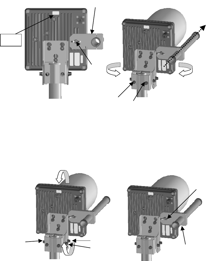
5-56
(f)
(e)
(d)
Direction adjustment
(a)
5.3.3. Direction adjustment of the antenna
Step1 Adjust the horizontal direction
- As shown in Figure 5-14, use the wing bolt (a) to attach the Antenna direction adjustment
tool.
- As shown in Figure 5-15, loosen the hexagonal socket head bolts (b) and (c) securing the
mounting bracket, swing the antenna left or right, and adjust the horizontal direction.
- Finally, tighten the bolts (b) and (c).(Recommended tightening torque: 8.5 N-m)
In figure is an example when the antenna type is the horizontal polarization.
Figure 5-14 Attaching the Direction Adjustment tool
Figure 5-15 Adjusting the Horizontal Direction
Step2 Adjust the vertical direction
- As shown in Figure 5-16, loosen the hexagonal socket head bolts (d), (e), and (f) securing
the mounting bracket, and tilt the antenna up or down to adjust the vertical direction.
- Tighten the bolts (d), (e) and (f). (Recommended tightening torque: 8.5 N-m)
- Finally, loosen the wing bolt (a) and remove the Antenna direction adjustment tool.
In figure is an example when the antenna type is the horizontal polarization.
Figure 5-16 Adjusting the Vertical Direction
Direction adjustment
TOP H
(a)
(b)
(C)
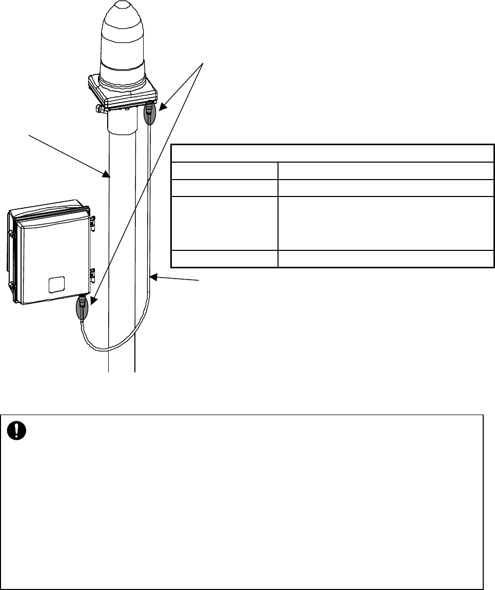
5-57
5.4. Connecting a Cable between AP-RFU and AP-IFU
5.4.1. AP-RFU (Omni Antenna)
Step1 Use the coaxial cable to connect the AP-RFU and the AP-IFU. (Figure 5-17)
Step2 Waterproof the connection with self-bonding tape or cold-shrinkable tube.
Figure 5-17 Connecting the Cable to the AP-RFU (Omni Antenna)
Connected cable between IFU and RFU
Cable type 5D-FB
Maximum length 110m
Recommended
characteristic Characteristic impedance : 50+2Ω
Attenuation(247.5MHz) : 0.135dB/m or less
Conductor resistance :
1.572Ω/loop・100m or less
Connector Shape N Type plug for coaxial
Pole
Coaxial cable with an N Type Plug
connector (IF cable)
Selfe Bonding tape and PVC tape
AP-IFU
AP-RFU
・ +16VDC to be supplied to the AP-
RFU is superimposed on the signals in the IF cable.
Turn off the power to the AP-IFU when installing or removing th
e IF cable. Otherwise, the
unit may be damaged.
・ Cover the cable connection with a cold-
shrinkable sleeve to make it waterproof.
Otherwise, water may get in the connection.
・ The curvature radius of the connection cable between the RFU and IFU should be 6 tim
es
or more the outer diameter of the cable.
・
When securing the connection cable between the RFU and IFU, be careful so the cable is
not deformed.
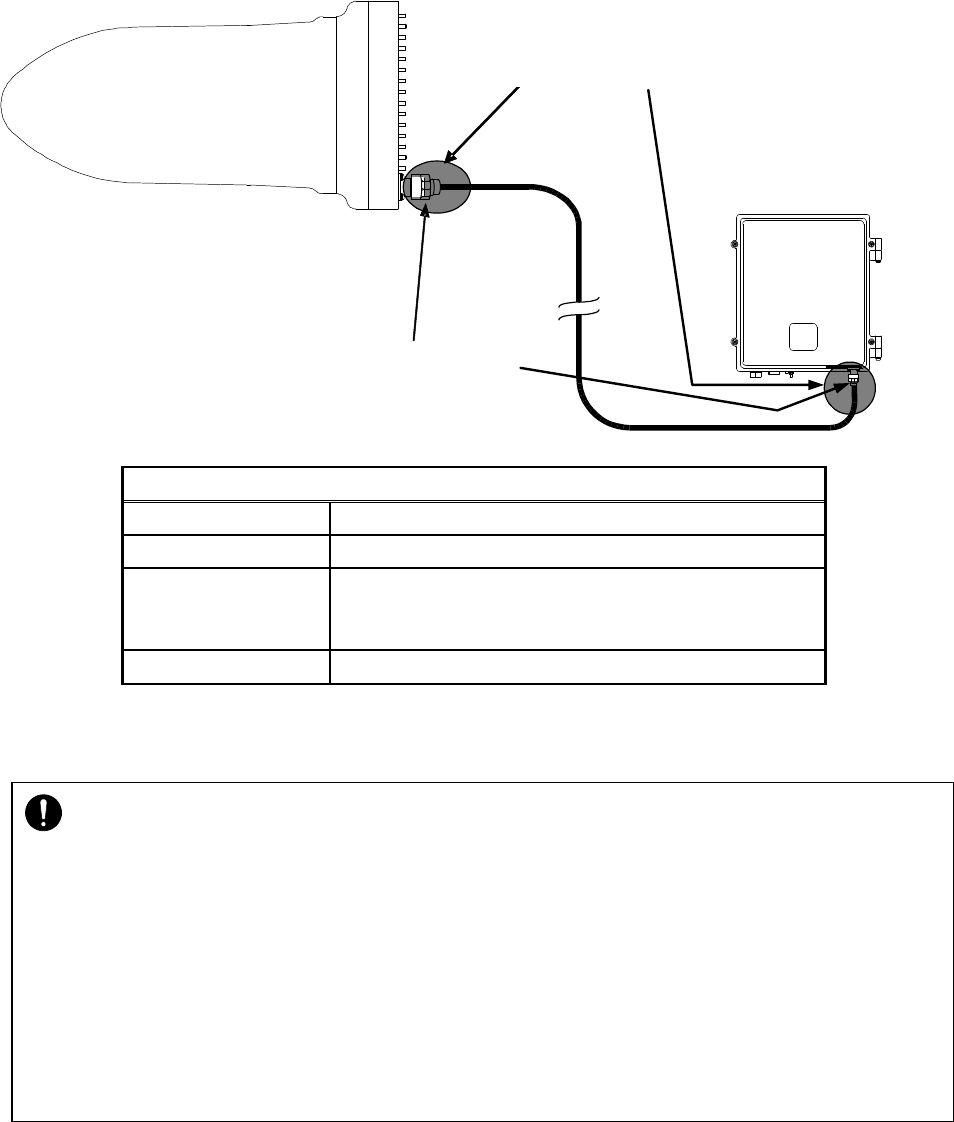
5-58
5.4.2. AP-RFU (Sectoral-Horn Antenna)
Step1 Use the coaxial cable to connect the AP-RFU and the AP-IFU. (Figure 5-18)
Step2 Waterproof the connection with self-bonding tape and PVC tape.
Figure 5-18 Connecting a Cable to the AP-RFU (Sectoral-Horn Antenna)
Connected cable between IFU and RFU
Cable type 5D-FB
Maximum length 110m
Recommended
characteristic Characteristic impedance : 50+2Ω
Attenuation(247.5MHz) : 0.135dB/m or less
Conductor resistance :1.572Ω/loop・100m or less
Connector Shape N Type plug for coaxial
AP-RFU
AP-IFU
Selfe Bonding tape and PVC tape
or
Cold-shrinkable sleeve
Coaxial cable with an N Type Plug
connector (IF cable)
Selfe Bonding tape and PVC tape
・ +16VDC to be supplied to the AP-RFU is superimposed on the s
ignals in the IF cable.
Turn off the power to the AP-
IFU when installing or removing the IF cable. Otherwise, the
unit may be damaged.
・ Cover the cable connection with a cold-
shrinkable sleeve to make it waterproof.
Otherwise, water may get in the connection.
・
The curvature radius of the connection cable between the RFU and IFU should be 6 times
or more the outer diameter of the cable.
・
When securing the connection cable between the RFU and IFU, be careful so the cable is
not deformed.
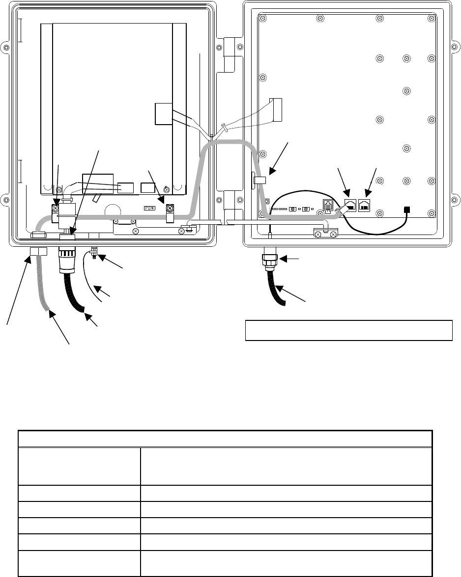
5-59
5.5. Connecting Cables from the AP-IFU to external
Step1 Connect four cables to the AP-IFU: a coaxial cable (with an N-type plug),
Ethernet cable, outdoor power supply cable, and ground wire.
Figure 5-19 Connecting Cables to the AP-IFU
(1) Ethernet Cable
Cable contents Connect the (a)ETHER1 connector.
Fix the cable by using (h), (i), (j) clamp in the AP-IFU.
Connect the external network through the (e)Ethernet cable inlet.
Interface 100BASE-Tx
Connector shape RJ-45
Pin assign ETHER signal(MDI)
Cable type Ethernet cable for outdoor
Range of applicable outer
diameter Φ5.5mm or less
(e) Ethernet cable
inlet (2) Outdoor power supply cable
(3) Ground wire
(More than 1.5
□
mm)
(g) FG terminal
(M4nut)
To AP-RFU(see
Figure
5
-
18
)
Use a T25 torx driver to open the AP-IFU cover
(a) ETHER1
(b) ETHER2
(c) MNT
(d) ANT terminal connector
(h) Clamp
(f) Power cable
connector
(i) Clamp
(j) Clamp
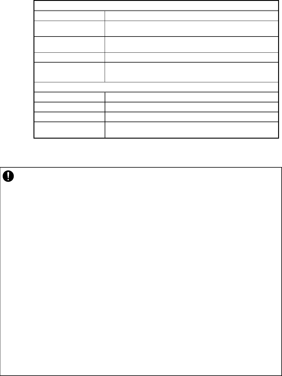
5-60
(2) Power cable
Contents Connect the power cable connector.
Equipment specification
of power DC-48V,35W(Max)
Range of applicable
outer diameter Φ7.0mm – Φ8.5mm
Connector name NRW-203-RM-ULCSATUV (Nanaboshi Electric MFG Co.,LTD.)
Applicable Connector NRW-203-PF8-ULCSAUV (Nanaboshi Electric MFG Co.,LTD.)
(This connector is supplied with AP-IFU.)
(3) Ground wire
Contents Connect the ground wire.
Applicable Cable Ground wire more than 1.5□
Applicable terminal FG terminal M4nut.
Method of processing
connector See Subsection 5.5.1
・ Ground wire more than 1.5□mm
・ FG terminal M4nut.
・ The DC -48V power supply voltage for AP-IFU shall be SELV or TNV-
1 depending on the
network environment (0 or 1) acc. to IEC62102.
・ The Equipment for connection to AP-IFU Ethernet-interface(RJ-
45) shall be appropriate to
connect to TNV-1 circuits.
・ For the connection Terminal Equipment to AP-
IFU and a cables suitable for outdoor use
shall be installed.
・ When opening the AP-IFU cover, make sure that the four special screws are
loosened
completely. Forcing open the cover may damage it.
・ +16VDC to be supplied to the AP-
RFU is superimposed on the signals in the IF cable.
Turn off the power to the AP-
IFU when installing or removing the IF cable. Otherwise, the
unit may be damaged.
・ Cover the cable connection with a cold-
shrinkable sleeve to make it waterproof.
Otherwise, water may get in the connection.
・ After you opened the AP-
IFU cover, make sure to secure it using the stopper. Otherwise,
you may get hurt. To close the cover, be sure to return the stopper to the original position.
・ For the connection AP-IFU to AP-
RFU and a coaxial cable suitable for outdoor use shall
be installed.
(1) Ethernet cable
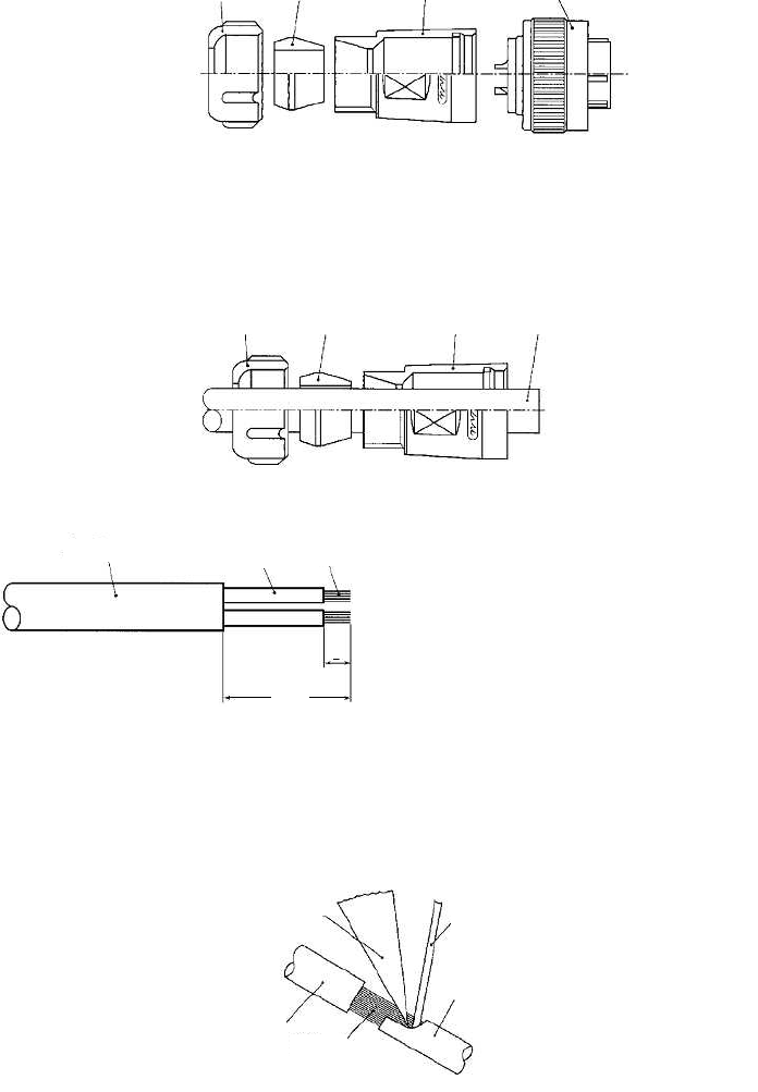
5-61
5.5.1. Connecting the Power cable connector
The connector manufacturer (Nanaboshi Electric MFG Co., Ltd.) recommends the following
method of cable connection.
(1) Disassemble the connector, as shown here.
(a) Remove the insert assembly from the end bell by turning the assembly counterclockwise.
(b) Loosen the clamping nut to remove the cable packing.
(2) Pass the cable through the disassembled parts in the sequence shown here.
Note: Be sure that all the parts are placed in the specified sequence and in the
correct direction.
(3) Peel the cable sheath and wires according to the dimensions specified here.
(4) Process the ends of the cable's core wires and pretin them.
Note: Do not pretin the cable sheath.
Note: When the cable core is pretinned, it should be uniform everywhere and smaller
than the diameter of the opening in the contact.
Clamping nut
Cabl
e
pakkin
End bell
Insert
a
ssembly
Clamping nut
Cabl
e
pakkin
End bell
Cab
le
Solder
Contact
Iron tip
Cable
Core
wire
Cable
Core wire
Sheath
18mm
7mm
Conductor cross
-
sectional area
2 mm
2
Cable outside diameter
7.0 to 8.5 mm
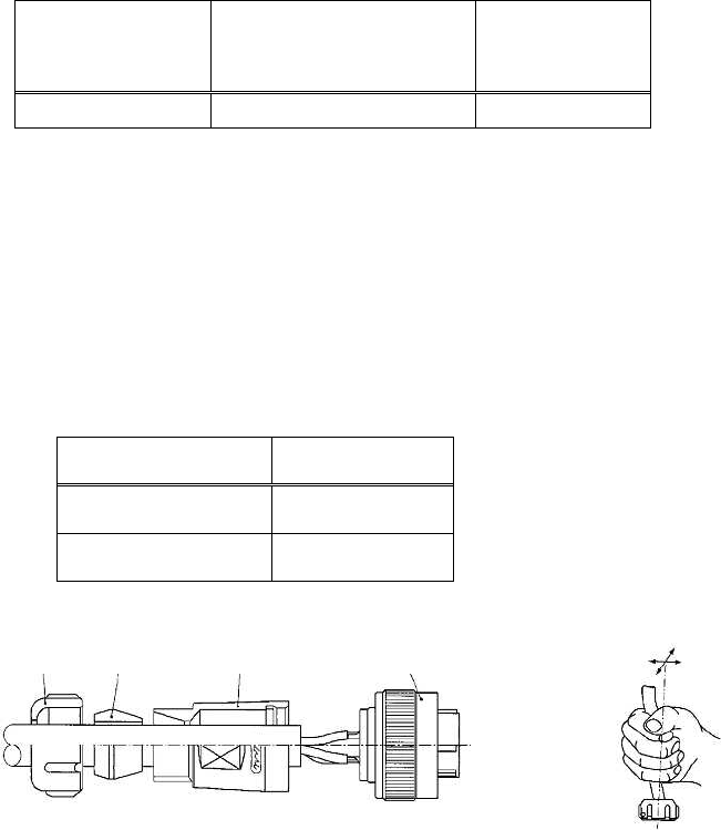
5-62
(5) Soldering
(a) Insert the pretinned core wires into the contact's solder pot.
(b) Using a soldering iron, heat the contact and the core wires.
(c) Let solder flow into the gap between the contact and the core wires until the gap is filled.
(6) Assemble the connector.
(a) Clamp the insert assembly and tighten the end bell with the specified torque.
(b) Push the cable packing into the end bell, clamp the end bell, and tighten the clamping nut
with the specified torque.
(c) Move the cable back and forth until it moves easily (as shown). Once again, tighten the parts
with the specified torque.
Soldering iron
wattage
[W]
Conductor
cross-sectional area
[mm2]
Iron tip
temperature
[℃]
30 2 350 to 370
Where to tighten Shell size: 20
End bell 1.0 to 1.5
Clamping nut 1.5 to 2.0 [Unit: N-m]
Clamping nut
Cabl
e
pakkin
End bell
Insert
a
ssembly

5-63
5.6. The confirmation of AP-IFU
Turn on the AP-IFU and check the state of the LEDs on the AP-IFU.
Table 5-1 LED State Indications
AP-IFU LED State
POWER LED Lit green
IFU STATE LED Flashing green
IFU ALM LED Off
ETHER1 LED Lit green or flashing
ETHER2 LED Off *1
ETHER1 AUTO LED Off *2
ETHER2 AUTO LED Off *3
*1 The LED lights if an Ethernet cable is connected to ETHER2.
*2 The LED lights if the ETHER1 switch is set at AUTO.
*3 The LED lights if the ETHER2 switch is set at AUTO.
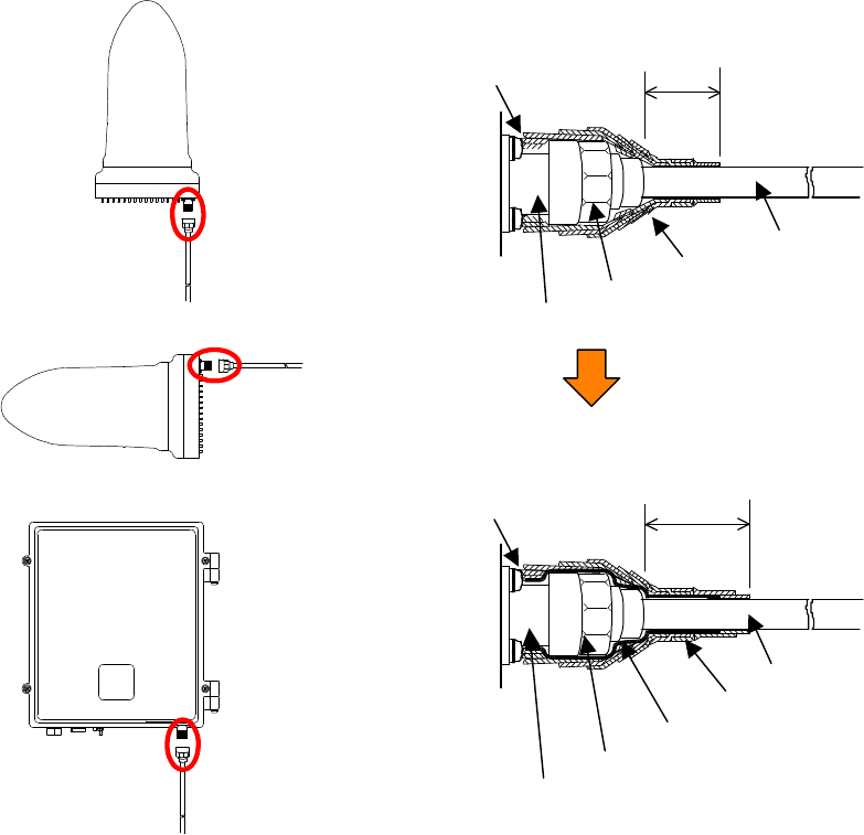
5-64
5.7. Waterproofing Connectors
5.7.1. Self Bonding tape
Figure 5-20 shows how to waterproof the connection using self-bonding tape.
Figure 5-20 Waterproofing a Connector Using Self-Bonding Tape
Waterproofing procedure
Step1 Wrap the self-bonding tape around the base of the N-type jack connector on the
unit side one complete turn. After one turn, wrap around the coaxial cable by
about 30 millimeters, overlapping one-half of the previous turn. Reverse the
wrapping direction back to the base of the N-type jack connector on the unit
side.
Step2 Wrap the PVC tape for class 2 protection around the coaxial cable starting from
the base of the N-type jack connector on the unit side by about 50 millimeters,
Space is not acceptable
Space is not acceptable
30mm
50mm
AP-RFU(Omni Antenna)
AP-RFU(Sectoral - Horn Antenna)
AP-IFU
Overlapping half of the previous layer
with self
-bonding tape (sectional view)
Overlapping half of the previous layer
with PVC tape (sectional view)
Self Bondin
g tape
PVC tape
Coaxial cable
N-type Plug connector
N-type Jack connector
Self Bonding tape
Coaxial cable
N-type Plug connector
N-type Jack connector

5-65
overlapping one-half of the previous turn so that the self-bonding tape is
completely hidden. Reverse the wrapping direction back to the base of the
N-type jack connector on the unit side.
・ For the stretching margin of self-bonding tape, see the instruction manual for the product.
・ Press evenly along the entire length of tape to remove air pockets.
・ Make sure that there are no air pockets between layers of the self-
bonding tape. Air
pockets will degrade the waterproofing effect.
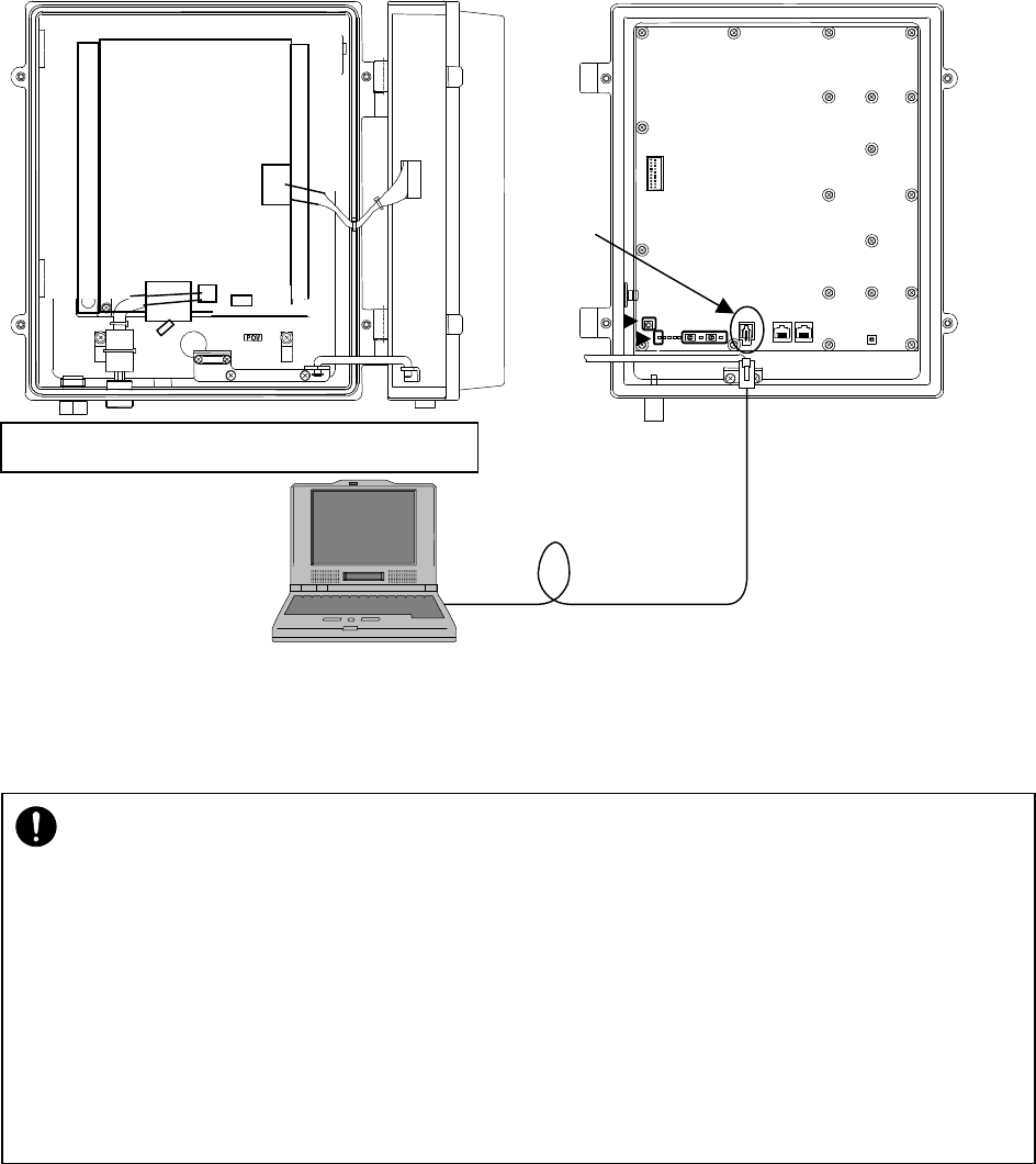
5-66
5.8. Connecting the AP Local Management Tool
Open the cover of the AP-IFU.
Connect the AP local management tool terminal to the MNT port of the AP-IFU using the AP local
management cable as shown in Figure 5-21
Figure 5-21 Connection
:
Use a T25 torx driver to open the AP-IFU cover.
MNT port
AP Local management tool(PC)
AP
Local management cable
・ When opening the AP-
IFU cover, make sure that the four special screws are loosened
completely. Forcing to open the cover may damage it.
・ After you opened the AP-IFU cover, make sure to secure it using the stopper. Other
wise,
you may get hurt. To close the cover, be sure to return the stopper to the original position.
・ If it is difficult to tighten the four special screws of the AP-
IFU cover, adjust the locations of
the screw holes (support the cover and align the top of t
he cover to that of the chassis)
and tighten the screws. Forced tightening of the screws may damage the cover and
screws.
・ When closing the cover, be careful not to nick cables.
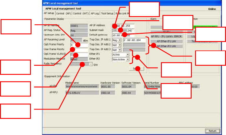
5-67
5.9. Configure the AP parameters
5.9.1. AP Local management tool
5.9.1.1. Configure the AP network parameters
Use the AP Local Management Tool to set the network parameters.
These settings enable the OpS to connect to the AP.
Perform the following setup procedure from the AP setup screen on the AP Local Management
Tool.
Step 1: OpS Frame Priority: Set the OpS frame priority.
Step 2: User Frame Priority: Set the user frame priority.
Step 3: OpS Frame VLAN-ID: Set the OpS frame Vlan-ID.
Step 4: Radio frequency: Set the radio frequency.
Step 5: AP IP Address: Set the AP IP address.
Step 6: Subnet mask: Set the subnet mask.
Step 7: Default gateway: Set the default gateway.
Step 8: Trap Des, IP Add. 1: Set the "Reg./Not" and trap destination IP address 1. Set
"Reg." or "Not" and set an IP address for trap destination IP address 1. If
necessary, you can also set Trap Des, IP Add. 2 and Trap Des, IP Add. 3.
Step 9: Ether-IF 1: Set whether to use Ether-IF 1. If necessary, you can also set Ether-IF
2.
Step 10: Click the Setup button.
Figure 5-22 Configure the AP network
Step1
Step2
Step3
Step4
Step5
Step6
Step7
Step8
Step9
Step10
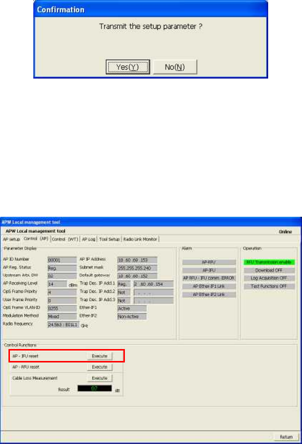
5-68
Step 11: when you click the button, a range check is performed. If the range check does
not detect any error, the Confirmation dialog box appears. Click the Yes (Y)
button.
If a range error is detected, a message saying that a setting value is outside the
range appears.
Figure 5-23 Confirmation Dialog Box
5.9.1.2. Reset the AP
Resetting the AP-IFU enables the AP network parameter settings.
To reset the AP-RFU, on the Control (AP) screen in the AL Local Management Tool, click the
Execute button. A confirmation dialog box appears. Clicking the Yes (Y) button executes a reset.
Figure 5-24 Reset the AP
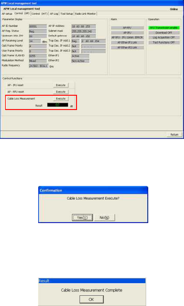
5-69
5.9.1.3. Measure the cable loss
Check that the cable between the AP-IFU and the AP-RFU is connected correctly, and start cable
loss measurement.
When the measurement of cable loss between the AP-IFU and the AP-RFU is completed, the
value is automatically compensated for.
The cable loss compensation value is stored in the memory in the AP-RFU.
Step 1: Select the Control (AP) screen in the AP Local Management Tool.
Step 2: In the Cable Loss Measurement field, click the Execute button.
Figure 5-25 Measure the cable loss
Step 3: The Confirmation dialog box appears. Clicking the Yes (Y) button executes the
measurement.
Figure 5-26 Confirmation Dialog Box
Step 4: If measurement ends normally, the Result dialog box appears. Click the OK
button to end the measurement process.
You can compensate for a cable loss of 0 to 15 dB
Figure 5-27 Cable Loss Measurement Complete
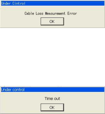
5-70
Step 5: If the procedure ends abnormally, the Under Control dialog box appears.
Check if the cable between the IFU and RFU is too long and there is a contact
failure at the connector section.
Figure 5-28 Cable Loss Measurement Error
Step 6: If the procedure ends normally, the Under Control dialog box appears.
Check if the cable between the IFU and RFU is connected correctly.
Figure 5-29 Time out
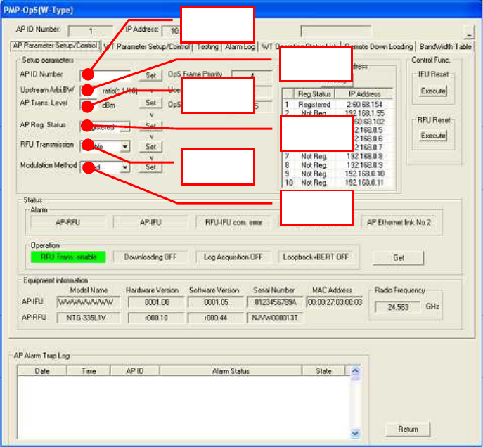
5-71
5.9.2. Register the AP ID number to OpS
Connect the OpS to the target AP and specify the setup parameters.
Procedure
Step 1: In the OpS, select the AP Parameter Setup/Control screen.
Step 2: AP ID Number: Set the AP ID number and click the Set button.
Step 3: Upstream Arbi. BW: Set the upstream arbitration bandwidth.
Step 4: AP trans. Level: Set the AP transmission level (You can set only +14dBm) and
click the Set button.
Step 5: AP Reg. Status: Set the AP registration status to Registered and click the Set
button.
Step 6: RFU transmission: Set the RFU transmission to Enable and click the Set button.
Step 7: Modulation Method: Set the modulation method to QPSK, 16QAM or Mixed, and
click the Set button.
Figure 5-30 Register the AP to OpS
Step1
Step2
Step3
Step4
Step5
Step6

5-72
5.10. Check sheet of AP Installation
You can use the check sheet below to check the operation of the AP.
Procedure
(A) LED operation test
- Turn off the AP-IFU and confirm that the "POWER" LED goes out.
- Turn on the AP-IFU and check the states of all the LED.
(B) Alarm operation test
- Turn on the AP-IFU and cause the "AP power recovery" trap to occur. Confirm
that the message "AP power recovery: Clear" appears in the list of OpS alarms.
(C) Control operation test
- Run the RFU Reset command from the OpS and cause the "AP RFU-IFU
communication error" trap to occur. Confirm that the message "AP RFU-IFU
communication error: Clear" appears in the list of OpS alarms.
Table 5-2 Check sheet
AP Serial number Test date
Test type Test condition Check item Pass/fail
LED operation
test When power is off
Confirm that the POWER LED is off.
When power is on
Confirm that the POWER LED lights green.
Confirm that the IFU STATE LED flashes green.
Confirm that the IFU ALM LED is off.
Confirm that the ETHER1 LED lights green or
flashes.
Confirm that the ETHER2 LED is off. *1
Confirm that the ETHER1 AUTO LED is off. *2
Confirm that the ETHER2 AUTO LED is off. *3
Alarm
operation test OpS
Confirm that the message "AP power recovery:
Clear" appears in the list of OpS alarms.
Control
operation test Running RFU
Reset from OpS
Confirm that the message "AP RFU-IFU
communication error: Clear" appears in the list of
OpS alarms.
*1 The LED lights if an Ethernet cable is connected to ETHER2.
*2 The LED lights if the ETHER1 switch is set at AUTO.
*3 The LED lights if the ETHER2 switch is set at AUTO.
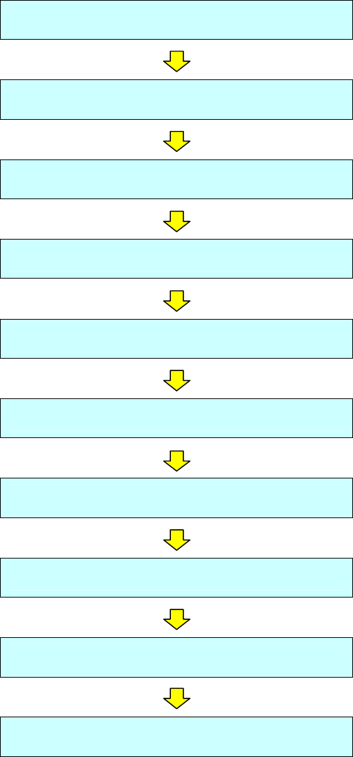
6-73
6. CONSTRUCTING A POINT-TO-MULTIPOINT SYSTEM
(WT)
6.1. Overview
OpS
Connecting the WT Local Management Tool
WT Local management tool
Installing the WT
Installing the WT Adapter
Connecting Cables to the WT
Waterproofing WT small window
Testing
Check sheet of WT Construction
Finish

6-74
6.2. OpS
6.2.1. Register the WT ID number to AP
Connect the OpS to the target AP and register a WT.
Step 1: In the OpS, select the WT Parameter Setup/Control tab.
Step 2: Select the WT from "Select WT ID number."
Step 3: Specify the setup parameters.
- VLAN-TAG Cont: Set the VLAN-TAG Cont to Transparent.
- Authen Param: Set the authentication parameter.
- Serial number: Set the serial number and click the Set button.
- WT Reg. Status: Set the WT registration status to Registered and click the Set button.
- Modulation: Set the modulation to QPSK, 16QAM, or Adaptive and click the Set button.
- Interface Class: Set the interface class to AUTO or 10BASE and click the Set button.
- RFU Transmission: Set the RFU Transmission to Enable and click the Execute button.
The following dialog box appears since a value is already set for "RFU
Transmission." Click the OK button.
- UP Stream Bandwidth table [Maximum Limit / Minimum Guarantee]
- Down Stream Bandwidth table [Maximum Limit / Minimum Guarantee]
Clicking the Set button displays a dialog box. Place checkmarks in the checkboxes and click the Set
button.
Step 4: Set the VLAN-ID.
- VLAN-ID: Set the VLAN-ID and click the Register button.
- Since the VLAN-ID that has been set appears on the screen, select it.
- VLAN-ID Registration status: Set the VLAN-ID registration status to Registered.
- Service status [ out of service / In service ] : Set the Service status to In service
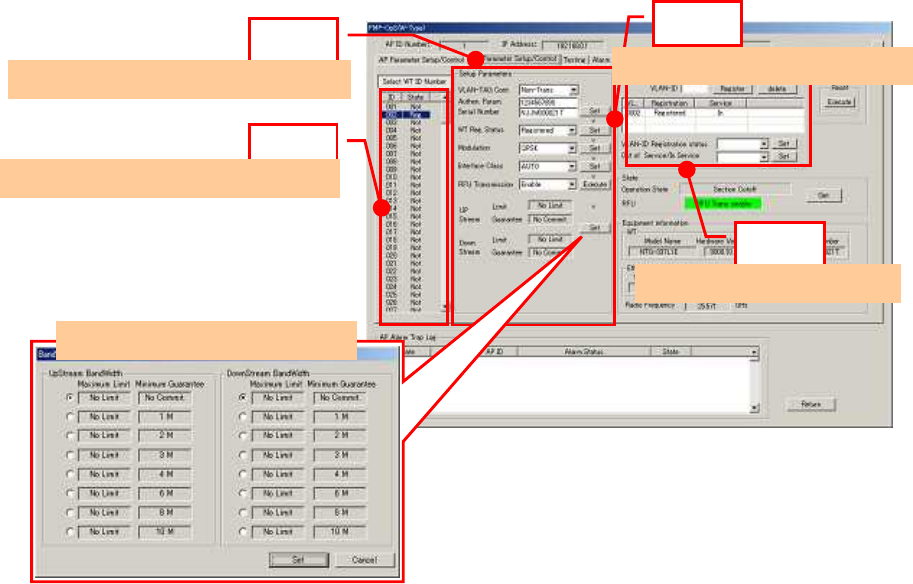
6-75
Figure 6-1 Register the WT ID number to AP
Step1
Step2
Step3
Step4
Set Bandwidth
table
Select [Parameter setup/control] tab
Select the WT ID number
set parameters
Set VLAN
-
ID
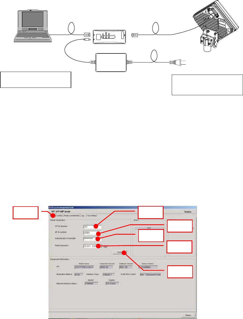
6-76
6.3. Connecting the WT Local Management Tool
Connect the WT local management tool terminal to the PC port of the WT adapter (Figure 6-2)
using a straight Ethernet cable.
Figure 6-2 Connection
6.4. WT Local management tool
6.4.1. Configure the WT
Use the WT Local Management Tool to specify the Setup Parameters.
Step 1: Select the Setup tab.
Step 2: Set the WT ID number.
Step 3: Set the AP ID number.
Step 4: Set the authentication parameter.
Step 5: Set the radio frequency.
Step 6: Click the Setup button.
Figure 6-3 Configure the WT
IP address: 192.168.1.200
Subnet mask: 255.255.255.0
WT adapter
AC Adapter AC100∼240V
DC24V
local management tool(PC)
Ethernet cable (Straight)
initial values
IP address:192.168.1.100
Subnet mask:255.255.255.0
Step 1
Step 2
Step 3
Step 4
Step 5
Step 6
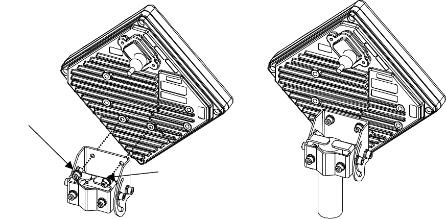
6-77
6.5. Installing the WT
6.5.1. Installing the WT
Step1 Attach the WT mounting bracket to the WT using the bolts(a)and (b).
You can orient the WT either for vertical or horizontal polarization.
Step2 Secure the WT mounting bracket to the pole using the bolts.
Applicable pole diameter: From Φ31.8mm to Φ34mm
Figure 6-4 Installing the WT
(a)
(b
)
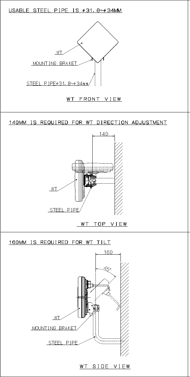
6-78
A builder prepares a steel pipe by the installation place (a wall, a pole or etc.), and it install.
The required space of installation is shown below.
Figure 6-5 The required space of installation
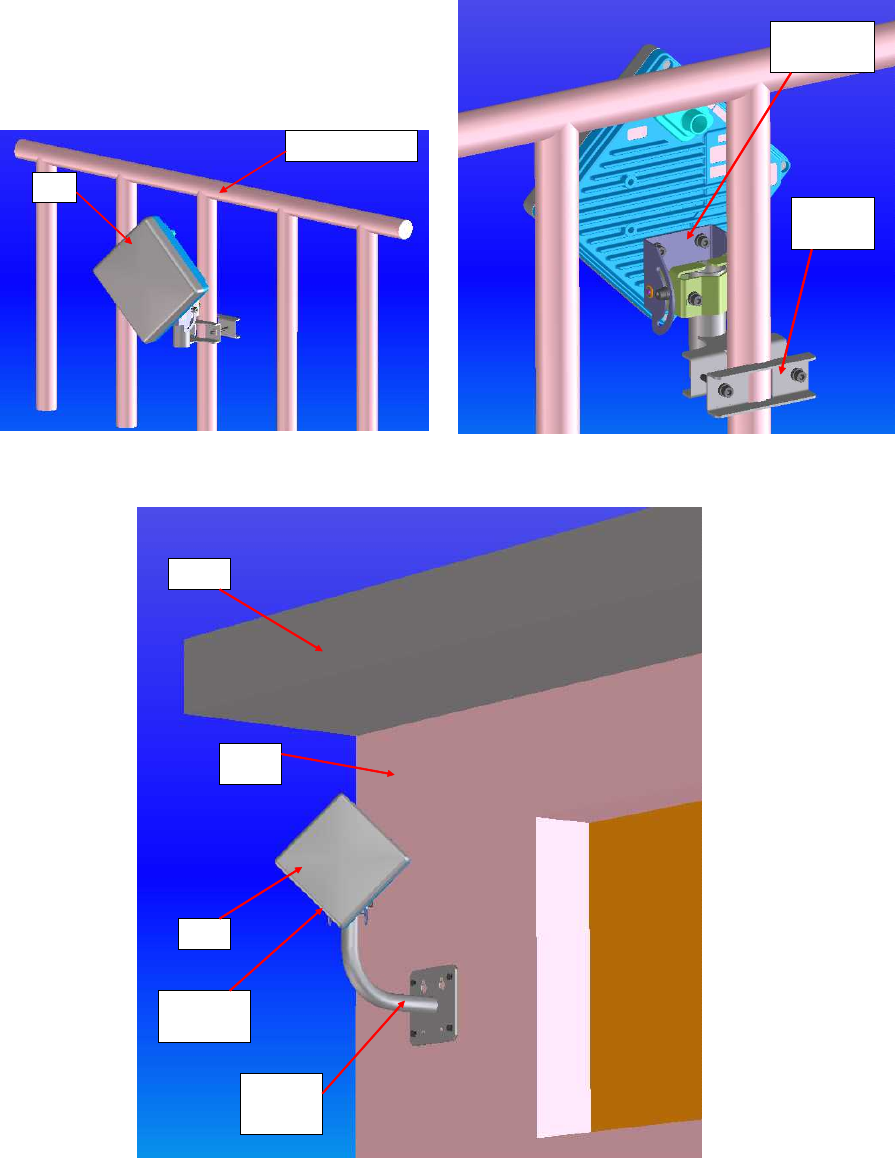
6-79
6.5.2. Example of Installing the WT
(1) On a metal fence
Figure 6-6 Installing on a metal fence
(2) On a house wall
Figure 6-7 Installing on a house wall
MOUNTING
BRACKET
FIXING
BRACKET
METAL FENCE
WT
EAVES
WT
MOUNTING
BRACKET
FIXING
BRACKET
WALL
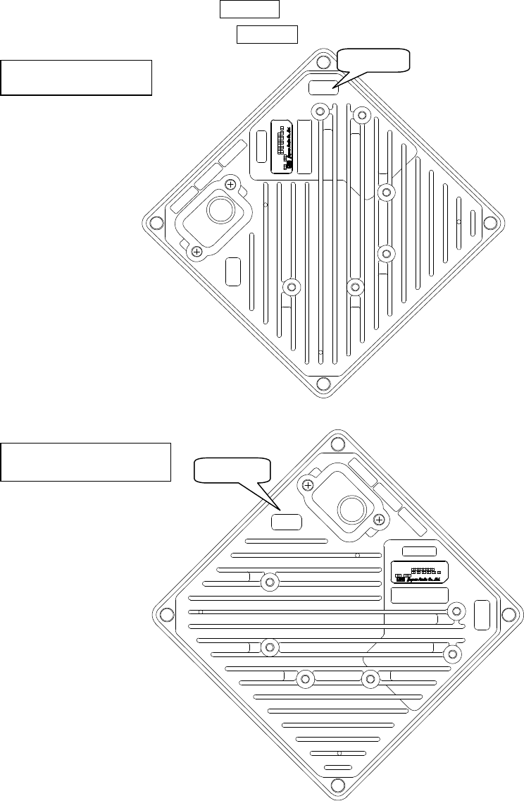
6-80
6.5.3. Setting the WT for Vertical or Horizontal Polarization
Rotate the antenna ninety degrees to choose between vertical or horizontal polarization
For vertical polarization, position TOP V at the top.
For horizontal polarization, position TOP H at the top.
Figure 6-8 Vertical Polarization
Figure 6-9 Horizontal Polarization
Vertical polarization
TOP V
TOP H
ETHE R
INPUT :
SER.NO :
MAC :
.:::::
MADE IN JAPAN
TYPEW−WT<EL0>
DC24V 0.7A
TOP V
Horizontal polarization
TOP V
TOP H
E T H E R
INPUT :
SER.NO :
MAC :
.:::::
MADE IN JAPAN
DC24V 0.7A
TYPEW−WT<EL0>
TOP H
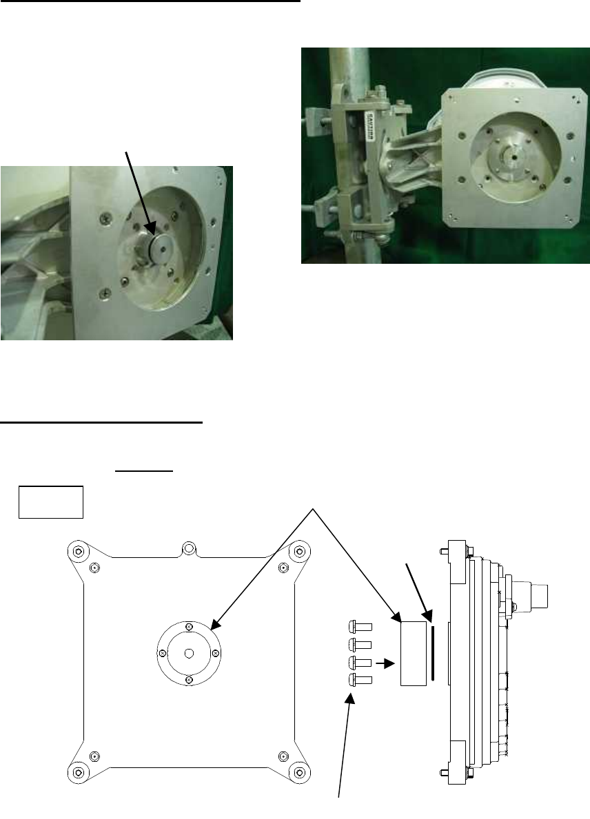
6-81
6.6. Installing the WT (External Antenna)
6.6.1. Installing the WT (ExternalΦ30cm Antenna)
1. Φ30cm antenna installation procedure
1) According to the antenna manual of RADIO WAVES, INC., set it up on the pole. (Figure 6-10)
2) Spread specified grease on the O-ring.
The spreading method depends on the
manual. (Figure 6-11)
Figure 6-10 Φ30cm antenna
Figure 6-11
2. WT installation procedure
Attach the antenna adaptor to the WT with the O-ring using four M3 screws. (Figure 6-12 & Figure 6-13)
Tightening torque:57 N・cm
Figure 6-12
M3 screws
O-ring
Adaptor
WT
O-ring

6-82
Figure 6-13
3. Attachment of the WT to the antenna
1) V(ertical) polarization
When using the V polarization, the guide pin of the WT should be turned to right above and inserted into
the V guide hole of the plate. (Figure 6-14 & Figure 6-15)
Figure 6-14
Figure 6-15
V polarization
Guide pin
I C: 76 8 B−N T G3 37 注 5
TOP V
T OP H
ET H ER
INPU T :
S E R . N O :
M A C :
.: : : : :
MADE IN JAP AN
DC2 4V 0.7A
TYPEW −W T < 注 1 >
FCCI D: C KENTG33 7 − 注 1
WT EL2
MODEL:NTG−337注2R
V guide hole
Plate
After installing the adaptor

6-83
After inserting the guide pin of the WT into the guide hole, presses the WT to the plate.
While you are pressing the WT, you must be tightening the four M5 screws. (Figure 6-16)
Tightening torque:265 N・cm
Figure 6-16
2) H(orizontal) polarization
When using H polarization, the guide pin of the WT should be rotated to the right and inserted into the H
guide hole of the plate. (Figure 6-17& Figure 6-18)
Figure 6-17 Figure 6-18
I C: 768B −NTG 33 7注5
T OPV
TOPH
ET HER
INPU T :
SER.NO :
M AC :
.: : :::
MADE IN JAPAN
DC24V 0 .7 A
T YPEW−WT<注1 >
F CCI D :C KENT G33 7 −注 1
WT E L2
MODEL:NTG−337注2R
Plate
M5 screws
Guide pin
IC:768B−NTG337注5
TOPV
TOP H
ETHER
IN P U T :
S E R . NO :
M A C :
.::: : :
MADE IN JAP AN
DC24V 0 .7A
TYP EW− W T < 注 1 >
F C CID:C KEN TG337 − 注 1
W T EL 2
MODEL:NTG−337注2R
Plate
H guide hole

6-84
After inserting the guide pin of the WT into the guide hole, presses the WT to the plate.
While you are pressing the WT, you must be tightening the four M5 screws. (Figure 6-19)
Tightening torque:265 N・cm
Figure 6-19
I C:76 8B −NTG 337注5
TOP V
TOP H
ETHER
INPUT :
SE R .NO:
MAC :
.::: : :
M AD E INJAPAN
DC24V 0. 7 A
TY P EW−WT<注1 >
FCCI D:CKE N TG3 3 7−注 1
WT EL2
MO DE L : N TG− 3 3 7 注2R
Plate
M5 screws
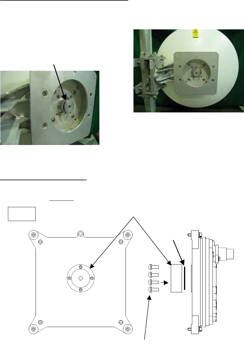
6-85
6.6.2. Installing the WT (ExternalΦ60cm Antenna)
1. Φ60cm antenna installation procedure
1) According to the antenna manual of RADIO WAVES, INC., set it up on the pole. (Figure 6-20)
2) Spread specified grease on the O-ring.
The spreading method depends on the
manual. (Figure 6-21)
Figure 6-20 Φ30cm antenna
Figure 6-21
2. WT installation procedure
Attach the antenna adaptor to the WT with the O-ring using four M3 screws. (Figure 6-22 & Figure 6-23)
Tightening torque:57 N・cm
Figure 6-22
M3 screws
O-ring
Adaptor
WT
O-ring

6-86
Figure 6-23
3. Attachment of the WT to the antenna
1) V(ertical) polarization
When using the V polarization, the guide pin of the WT should be turned to right above and inserted into
the V guide hole of the plate. (Figure 6-24 & Figure 6-25)
Figure 6-24
Figure 6-25
V polarization
Guide pin
After installing the adaptor
V guide hole
Plate
T OPV
TOP H
ETHER
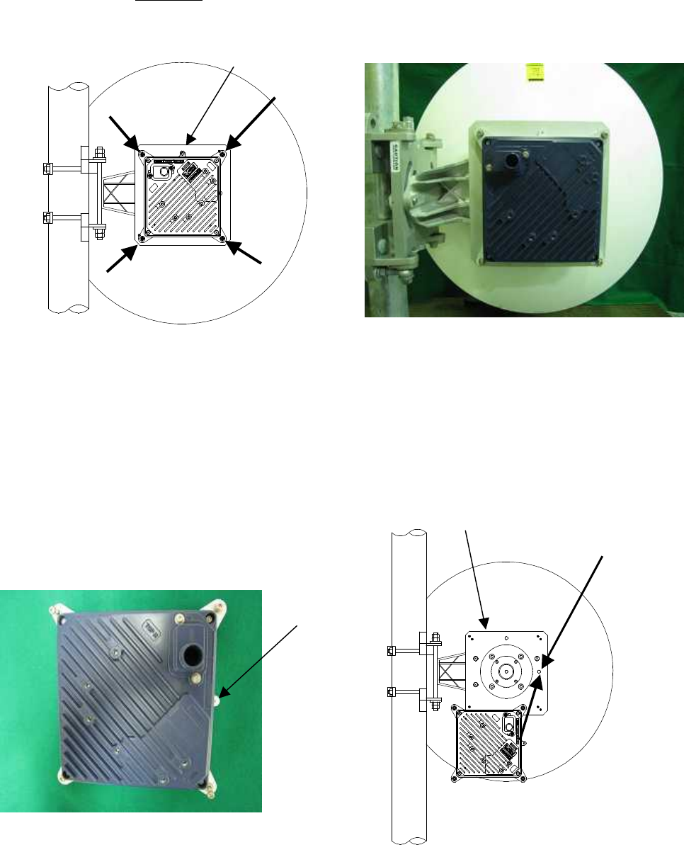
6-87
After inserting the guide pin of the WT into the guide hole, presses the WT to the plate.
While you are pressing the WT, you must be tightening the four M5 screws. (Figure 6-26)
Tightening torque:265 N・cm
Figure 6-26
2) H(orizontal) polarization
When using H polarization, the guide pin of the WT should be rotated to the right and inserted into the H
guide hole of the plate. (Figure 6-27 & Figure 6-28)
Figure 6-27 Figure 6-28
Guide pin
Plate
M5 screws
T OP V
TOPH
ETHER
WT E L 2
Plate
H guide hole
TO P V
T OPH
E T H E R
WT EL2
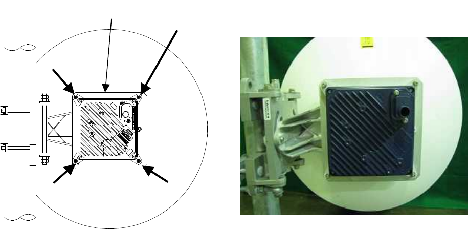
6-88
After inserting the guide pin of the WT into the guide hole, presses the WT to the plate.
While you are pressing the WT, you must be tightening the four M5 screws. (Figure 6-29)
Tightening torque:265 N・cm
Figure 6-29
Plate
M5 screws
TOPV
T OP H
ETHER
WT E L 2
6-89
6.7. Adjusting the Direction of the WT
To adjust the direction of the WT antenna, use the Antenna direction adjustment tool together with
the WT Local Management Tool.
Step1 Connecting the WT Local Management Tool and display the Receiving Level.
- See Subsection 6.7.1
Step2 Rough adjustment
- Install the Antenna direction adjustment tool.
- See Subsection 6.7.2
Step3 Fine adjustment
- See Subsection 6.7.3
Step4 Verification
- After adjust the direction, use the WT Local Management Tool to final check the receive
level.
If the receive level value is within the standard range, the procedure for adjusting the
antenna direction has been completed.
If the receive level value is lower than a standard value, you need to perform Step 3 again.
- Exit the WT Local Management Tool, and remove the Ethernet cable from the WT
adapter.
- Remove the Antenna direction adjustment tool.
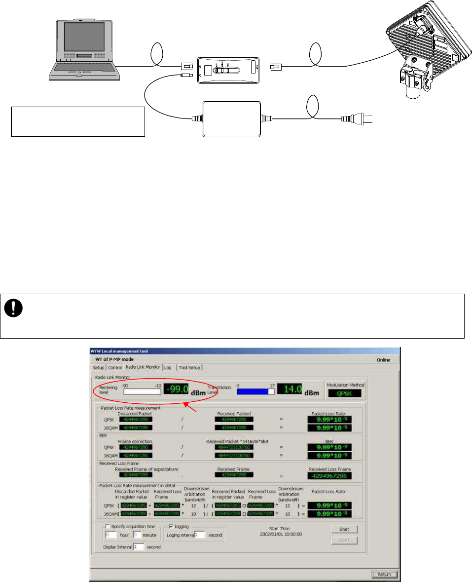
6-90
6.7.1. Connecting the WT Local Management Tool
(1) As shown in Figure 6-30, connect the WT Local Management Tool (PC) to the WT adapter.
Figure 6-30 How to Install the Cabling
(2) Method of measuring the receive level of the WT (P-MP mode)
STEP1 Start the WT Local Management Tool in P-MP mode.
STEP2 Go to the Radio Link Monitor screen of the WT in P-MP mode and display the Receiving
Level.
The procedure is shown in Figure 6-31.
Figure 6-31 Method of Measuring the Receive Level
WT adapter
AC Adapter AC100∼240V
DC24V
local management tool(PC)
Ethernet cable (Straight)
IP address: 192.168.1.200
Subnet mask: 255.255.255.0
・
The Receiving Level provides a display interval of 1 second, and you need to adjust the
antenna direction slowly.
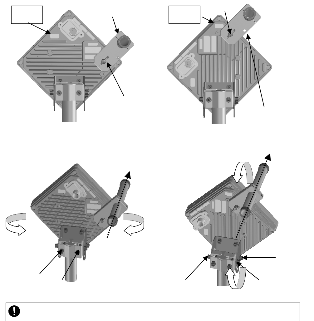
6-91
(f) (e)
(d)
(b) (C)
6.7.2. Roughly Adjusting the Direction
Step1 As shown in Figure 6-32 and Figure 6-33, use the wing bolt (a) to attach the Antenna
direction adjustment tool.
Step2 As shown in Figure 6-34, loosen the hexagonal socket head bolts (b) and (c) securing the
mounting bracket and swing the antenna left or right. Adjust the antenna approximately for
the WT direction and finger-tighten the bolts (b) and (c).
Step3 As shown in Figure 6-35, loosen the bolts (d), (e), and (f) and tilt the antenna up or down.
Perform vertical-direction adjustment so that the WT of the opposite station can be seen
through the scope of the Antenna direction adjustment tool.
Figure 6-32 How to Install Direction Adjustment tool
when the antenna type is the horizontal polarization
Figure 6-33 How to Install Direction Adjustment tool
when the antenna type is the vertical polarization
In Figure 6-34 and Figure 6-35 is an example when the antenna type is the horizontal polarization.
Figure 6-34 Rough-adjusting Horizontal Direction Figure 6-35 Rough-Adjusting the Vertical Direction
・ Never look at the sun directly. Doing so may seriously damage the eyes.
Direction adjustment tool
TOP V
(a)
TOP H
Direction adjustment tool
(a)
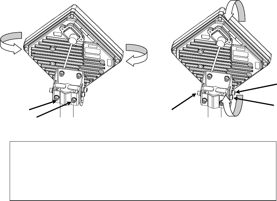
6-92
6.7.3. Finely Adjusting the Direction
Step 1: Horizontal direction
As shown in Figure 6-36, loosen the hexagonal socket head bolts (a) and (b) securing the
mounting bracket and swing the antenna left or right. Adjust the antenna direction so that the
receive level indicates the maximum value, and finger-tighten the bolts (a) and (b).
Step 2: Vertical direction
As shown in Figure 6-37, loosen the hexagonal socket head bolts (c), (d), and (e) securing the
mounting bracket and tilt the antenna up or down. Adjust the antenna direction so that the
receive level indicates the maximum value. Tighten the bolts at a point showing the maximum
receive level (tightening torque: 8.5N•m). Tighten the bolts (c), (d), and (e) and make sure that
the point showing the maximum receive level is maintained. This concludes the procedure for
vertical-direction adjustment.
Step 3: Horizontal direction
Finely adjust the horizontal direction by slightly loosening the bolts (a) and (b) again. Once
again, locate the point where the receive level reaches the maximum value and hold that point.
Finally, tighten the bolts (a) and (b) (tightening torque: 8.5N•m) while making sure that the
point showing the maximum receive level is maintained. This concludes the procedure for
horizontal-direction adjustment.
The figures show examples of horizontal polarization setup.
Figure 6-36 Finely Adjusting the Horizontal Direction
Figure 6-37 Finely Adjusting the Vertical Direction
(a)
(b)
(d)
(c)
(e)
Note : When adjusting the antenna direction
When adjusting the direction, you might mistakenly take the antenna's side lobe as
the maximum receive level. For fine adjustment, therefore, you should move the
antenna some more after the receive level has reached the ma
ximum value to make
sure that you have not caught a side lobe.
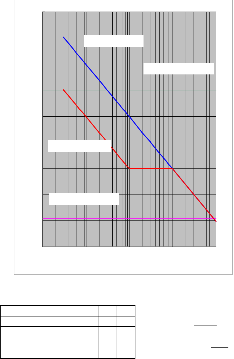
6-93
6.7.4. The receive level and the distance
For the receiving AP-RFU (Sectoral-Horn Antenna) in a point-to-multipoint system, the receiving
level at clear sky and the distance are related as shown in Figure 6-38.
Figure 6-38 Receiving Level and Distance (Sectoral QPSK)
-90
-80
-70
-60
-50
-40
-30
-20
-10
0
1 10 100 1000 10000
Distance[m]
Receiving Level [dBm]
Maximum Receiving Level
WT Receiving Level
AP Receiving Level
Minimum Receiving Level
Transmission level (QPSK) 14 [dBm] Free space loss Lp[dB]
Frequency 26 [GHz]
Antenna gain[TX+RX]
TX Sectoral Antenna Gain:15.5dBiTYP
RX WT Antenna Gain:31dBiTYP
46.5 [dBi]
λ
πd
Lp 4
log20
Hzf
mc
mλ
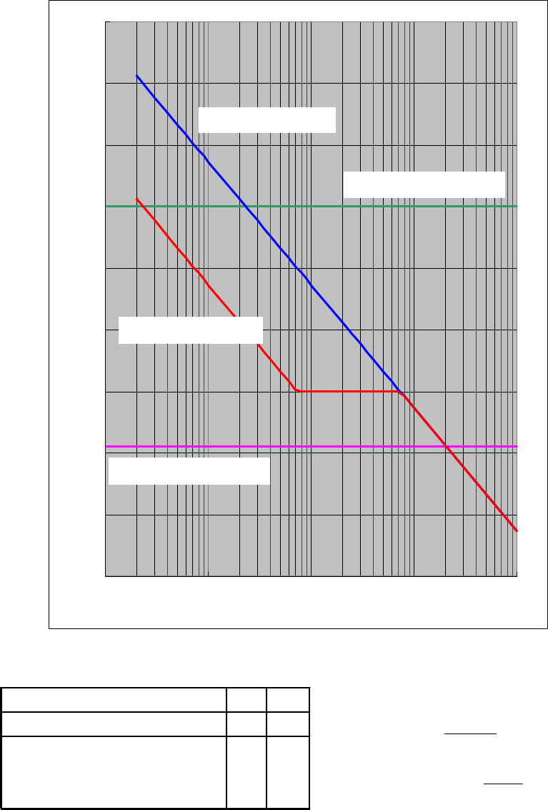
6-94
Figure 6-39 Receiving Level and Distance (Sectroral 16QAM)
-90
-80
-70
-60
-50
-40
-30
-20
-10
0
1 10 100 1000 10000
Distance[m]
Receiving Level [dBm]
Transmission level (QPSK) 11.5 [dBm] Free space loss Lp[dB]
Frequency 26 [GHz]
Antenna gain[TX+RX]
TX Sectoral Antenna Gain:15.5dBiTYP
RX WT Antenna Gain:31dBiTYP
46.5 [dBi]
λ
πd
Lp 4
log20
Hzf
mc
mλ
WT Receiving Level
Maximum Receiving Level
AP Receiving Level
Minimum Receiving Level
(16QAM)
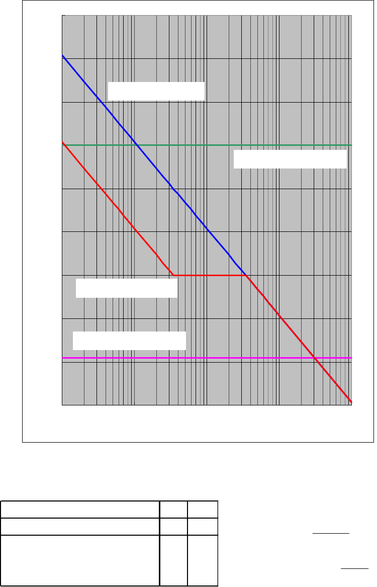
6-95
Figure 6-40 Receiving Level and Distance (Omni QPSK)
-90
-80
-70
-60
-50
-40
-30
-20
-10
0
1 10 100 1000 10000
Distance[m]
Receiving Level [dBm]
Transmission level (QPSK) 14 [dBm] Free space loss Lp[dB]
Frequency 26 [GHz]
Antenna gain[TX+RX]
TX Sectoral Antenna Gain:6.5dBiTYP
RX WT Antenna Gain:31dBiTYP
37.5 [dBi]
λ
πd
Lp 4
log20
Hzf
mc
mλ
Maximum Receiving Level
AP Receiving Level
Minimum Receiving Level
WT Receiving Level
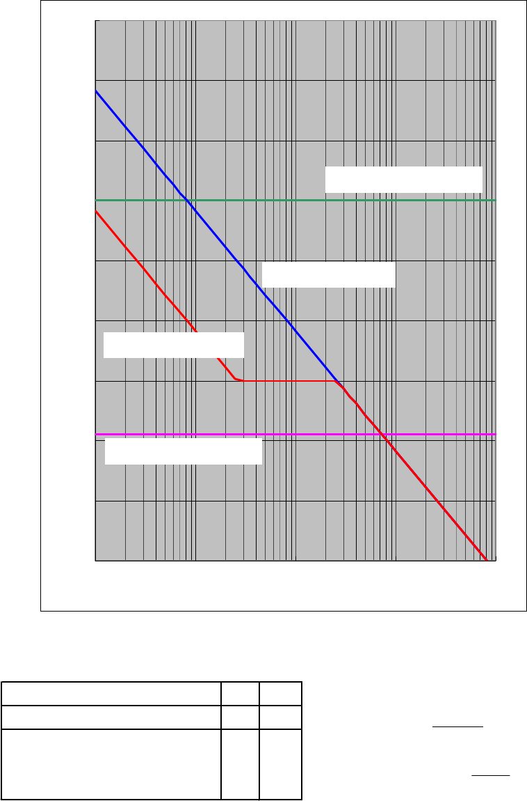
6-96
Figure 6-41 Receiving Level and Distance (Omni 16QAM)
-90
-80
-70
-60
-50
-40
-30
-20
-10
0
1 10 100 1000 10000
Distance[m]
Receiving Level [dBm]
Transmission level (QPSK) 11.5 [dBm] Free space loss Lp[dB]
Frequency 26 [GHz]
Antenna gain[TX+RX]
TX Sectoral Antenna Gain:6.5dBiTYP
RX WT Antenna Gain:31dBiTYP
37.5 [dBi]
λ
πd
Lp 4
log20
Hzf
mc
mλ
(16QAM)
WT Receiving Level
Maximum Receiving Level
AP Receiving Level
Minimum Receiving Level

6-97
6.8. Installing the WT Adapter
WT Adapter is installed in indoor
It is an example of installing the appended wood screw.
Screw into the mounting position the wood screw that comes with the WT adapter, leaving 2 mm.
Hook the WT adapter on the wood screw.
Wood Screw
Figure 6-42 Installing the WT Adapter on the Wall
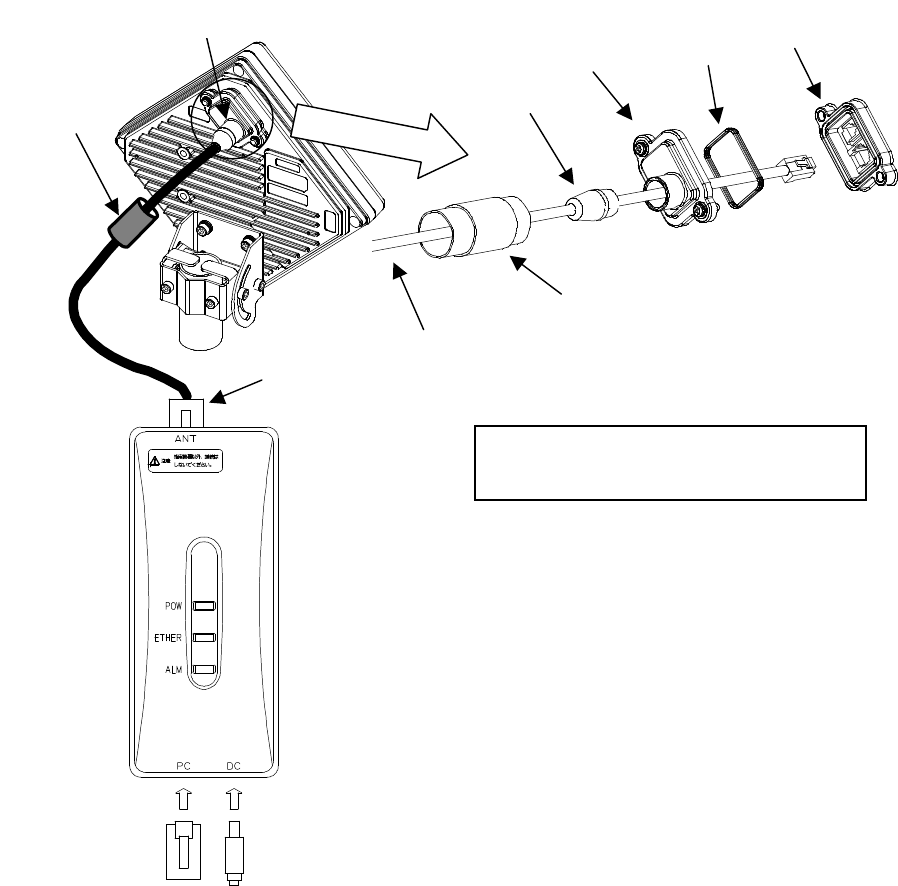
6-98
6.9. Connecting Cables to the WT
Use an Ethernet cable (straight) to connect the WT and the WT adapter as shown in Figure 6-43.
Figure 6-43 Connecting Cables to the WT
MDI
MDI-X
WT adapter
Cold-shrinkable tube
Small
Lid
Rubber
Ethernet cable (Straight)
You will need a Torx screwdriver (VESSEL
T20H-120) to open the small cover of the WT
AC adapter
User Terminal
WT
Cold-shrinkable tube
Spacer
Small
Window
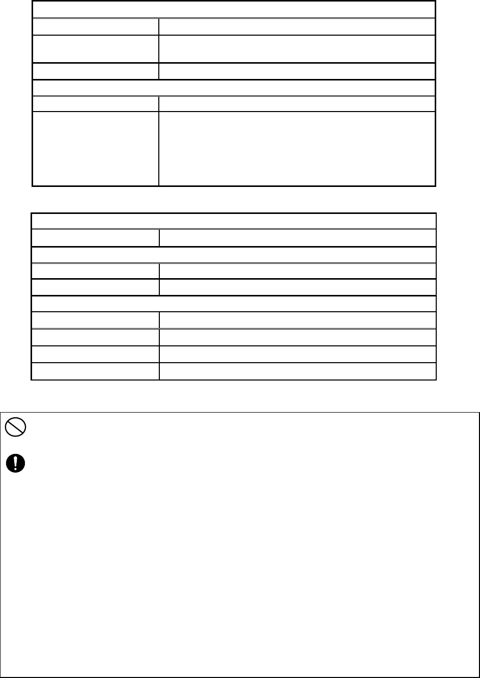
6-99
(1) Connected cable between WT and ANT port of WT adapter
(2) Connect the user terminal to PC port of WT adapter
(3) Connect the AC adapter to DC port to the WT adapter
Cable
Cable type Ethernet cable for outdoor,straight
Range of applicable outer
diameter φ5.0 mm∼5.7mm
Cable length 50m (maximum)
Connector of both side
Shape RJ-45
Cable connection Straight connection
- WT : MDI
- ANT port of WT adapter : MDI-X
An Ethernet cable has eight signal lines. Four lines are
used to carry Ethernet signals. The remaining four lines are
used as power lines and LED control lines.
Interface
Interface 10BASE-T/100BASE-TX
Connector
Shape RJ-45
Pin assign Ethernet signal(MDI-X)
Cable
Communication terminal Cable connection
PC straight
HUB crossover
ROUTER straight
・
Never connect your personal computer to the ANT port of the WT adapter. Doing so may
damage your personal computer.
・ The cable connecting between
the WT and WT adapter carries 24 VDC for the WT in
addition to Ethernet signals. Before unplugging the cable connecting between the WT and
WT adapter, make sure to unplug the DC jack of the WT adapter to turn the power off.
Otherwise, the unit may be damaged.
・
When closing the small window, make sure that the rubber packing of the small window is
free from any foreign matter.
・
The cable connecting the WT and WT adapter is a straight cable. Wrong connection may
damage the unit.
・ The Equipment for connection to WT adapter PC-interface(RJ-45) shall be appropriate to
connect to TNV-1 circuits.
・
For the connection WT adapter to WT and a cable suitable for outdoor use shall be
installed.
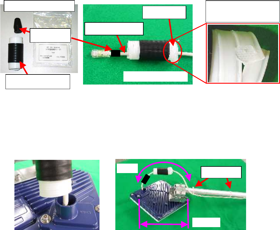
6-100
6.10. Waterproofing WT small window
(1) Pass the Ethernet cable through the cold-shrinkable tube (a) from the bonded portion of the
spiral tube. Pay attention to the insertion direction (Figure 6-45).
Applicable LAN cable diameter: 5.0 mm to 5.7 mm
Figure 6-44 Figure 6-45
(2) Connect the Ethernet cable to the WT (Figure 6-46).
(3) Using cable ties (c) or the like, secure the Ethernet cable to the supporting bracket. Attach the
cable ties 70 to 100 mm from the end of the supporting bracket. The cable is approximately
300 mm long measured from the cable joint (with a diameter of approximately 200 mm) to the
first cable tie (Figure 6-47).
Figure 6-46 Figure 6-47
(d) Spacer
(a) Cold-shrinkable tube
Pay attention to the irection
(b) Ether
net cable
Bonding portion of the spiral
tube for the cold-shrinkable
Components of CS sleeve
(e) Spiral tube
(c Cable ties
φ200mm
300mm
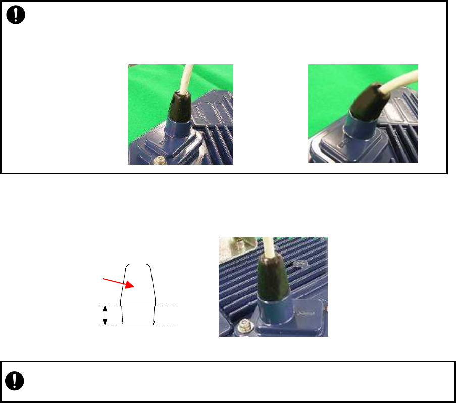
6-101
(4) Mounting spacer (d)
- Mount the spacer on the Ethernet cable .
- Make sure that the spacer is fully inserted in the small Lid of the WT(Figure 6-49).
Figure 6-49
(5) Mounting cold-shrinkable tube (a)
- Place the cold-shrinkable tube on the spacer and small Lid (Figure 6-50).
- Butt the end of the cold-shrinkable tube against the base of the small Lid. Pulling white
spiral tube (e) to the very edge of the cold-shrinkable tube eases the subsequent
procedure (Figure 6-50).
- Pull the spiral tube to mount the edge of the cold-shrinkable tube on the small Lid (Figure
6-51). Make sure that there is no gap between the cold-shrinkable tube and the base of
the small Lid and between the spacer and the small Lid.
- Pull the spiral tube to mount the cold-shrinkable tube, paying attention so the spacer is
not lifted (Figure 6-52 and Figure 6-53). Make sure that the spacer is not protruded from
the cold-shrinkable tube. The top of the cold-shrinkable tube should be 5 mm or less from
the top of the spacer.
・
Never allow the inside of the small window to become wet. Dampness may cause a
malfunction. Connect the Ethernet cable perpendicular to the WT. Failure to do so
will spoil the waterproofing effect, resulting in a device malfunction.
Bent cable
Cable perpendicular
to the WT
OK
(d)
Inserted
Spacer
・
Insert the spacer into the small window fully. Partial insertion of the spacer will spoil the
waterproofing effect.
NG
Figure 6-48
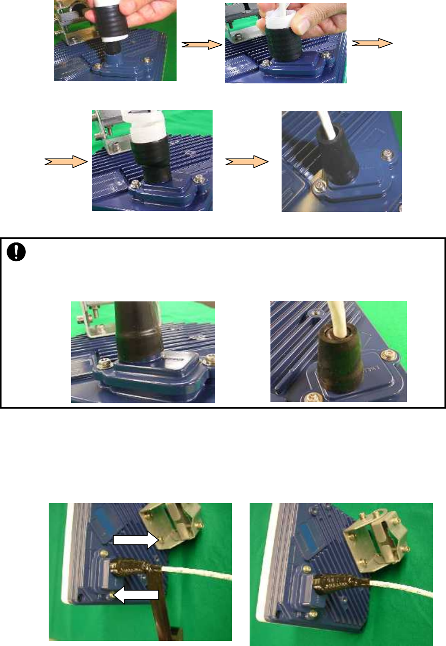
6-102
Figure 6-50 Figure 6-51
Figure 6-52 Figure 6-53
(6) Wrap the cable with PVC tape (for class 2 protection).
Apply the PVC tape so that the cold-shrinkable tube is completely hidden. Wrap the tape from
the small Lid of the WT to the Ethernet cable, overlapping half of the previous layer. Next,
reverse the wrapping direction and wrap one more time to the starting point.
・ Slanted mounting of the cold-
shrinkable tube as shown below will spoil the
waterproofing effect. If the top of the cold-
shrinkable tube is 5 mm or less from the
top of the spacer, this will also spoil the waterproofing effect.
NG
NG
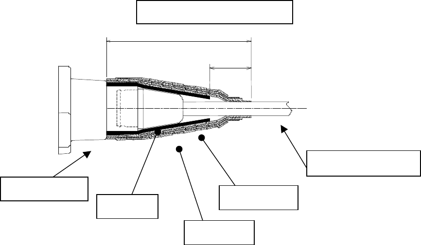
6-103
Length of PVC tape wrapping
Small window
Ethernetcable cable
Spacer CS sleeve
PVC tape
65
22
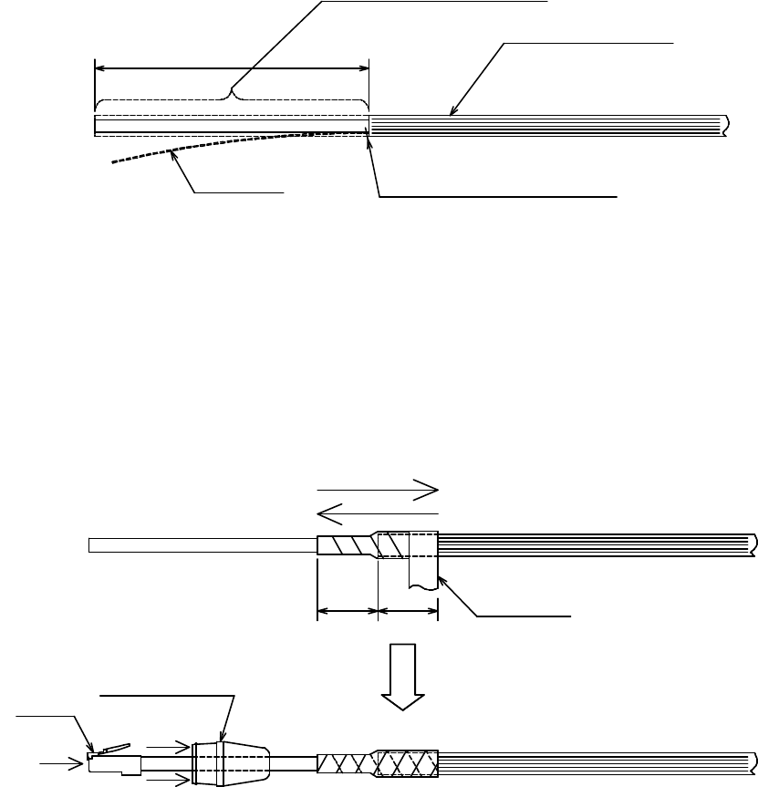
6-104
6.11. When you use the cable with the LAP sheath for outdoor
1.Processing of LAP sheath
- The LPA sheath is peeled off from the cable point to 120mm.
- It cuts it in the part peeled off when there is drain wire.
2.Processing of cutting part
- To prevent water being infiltrated in the wire, the self-bonding tape is rolled in the part
where the LAP sheath was peeled off as shown in the figure below.
- The Ether plug is installed with the normal temperature shrinkage sleeve and Spasa
passed.
3.Fixation of cable Ethernet、Installation of Spacer and normal temperature shrinkage sleeve
- See「6.9. Waterproofing WT small window」
4.Wrapping of PVC tape for protection
- It wraps until the self-bonding tape in the LAP sheath processing part is completely hidden
120mm
The cable with the LAP sheath
Drain
wire
is cut on the LAP sheath side.
Drain Wire
50mm
25
25
Self-bonding
Spacer
Connector
Push
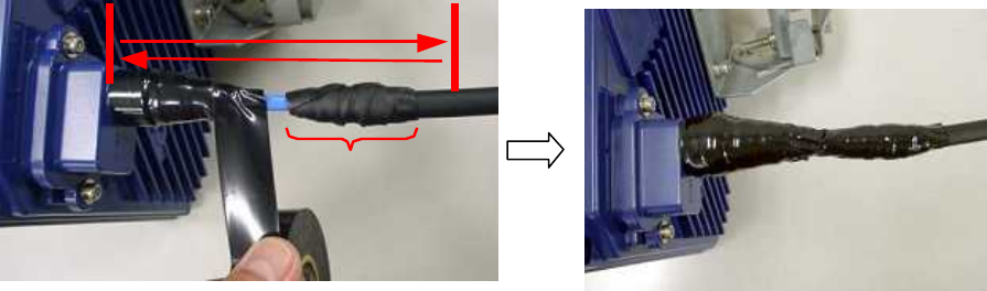
6-105
from a small window to the Ethernet cable side by 1/2 coming in succession, and 1 return
round trip to the small window side.
Self-bonding tape part
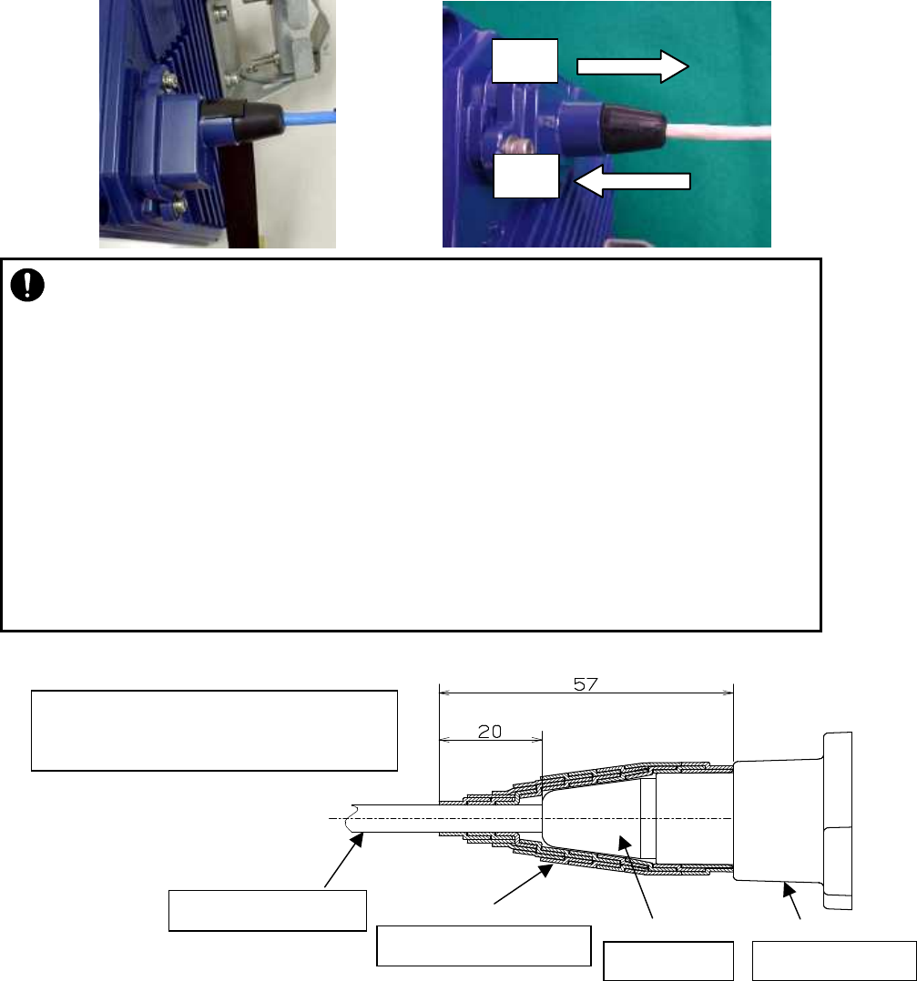
6-106
START
END
Overlapping half og the previous layer
(cross-sectional view)
Ethernet cable
Spacer
Small window
Se
lf
-
bonding tape
6.12. Waterproofing Without Using a Cold-Shrinkable Tube
If installing a cold-shrinkable tube fails, use off-the-shelf self-bonding tape to provide the
waterproofing.
(1) Securing the small Lid of the WT and the spacer
Using an appropriate length of self-bonding tape, wrap the tape around both the small Lid of
the WT (at its base) and spacer one complete turn. After one turn, wrap about seven turns
around the Ethernet cable by overlapping one-half of the previous turn. Reverse the wrapping
direction and wrap about another seven turns back to the small Lid.
・ For the stretching margin of self-bonding tape, see t
he instruction manual for the
product.
・ When wrapping self-
bonding tape, start at the base of the small window and end at
the end of the waterproof sleeve. Next, reverse the direction and end at the base of
the small window. This procedure makes an attracti
ve wrapping and improves the
waterproof effect by making any air pocketsless likely.
・ Overlapping the wraps also protects against air pockets.
・ Press evenly along the entire length of tape to remove air pockets.
・ Make sure that there are no air pockets between the self-
bonding tape and the small
window of the WT or the rubber bushing. Air pockets will degrade the waterproofing
effect.
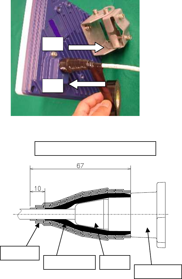
6-107
(2) Wrapping protective PVC tape
Apply the protective PVC tape so that the cold-shrinkable tube is completely hidden. Wrap the
tape from the small Lid of the WT to the Ethernet cable, overlapping half of the previous layer.
Next, reverse the wrapping direction and wrap one more time to the starting point. Using the
PVC tape will guard the self-bonding tape against ultraviolet and other rays. The wrapping also
helps increase strength.
Key point: When wrapping PVC tape, be sure that the self-bonding tape is completely covered
for its protection.
PVC tape
Self-
bonding
Spacer
Small
Length of PVC tape used for
START
END
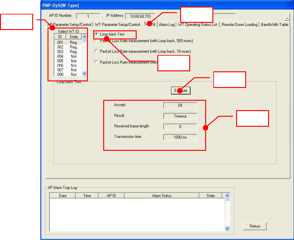
6-108
6.13. Testing
6.13.1. Perform a continuity test
Connect the OpS terminal to an AP, and run a loopback test with the following procedure:
Step 1: Click the Testing tab.
Step 2: Select a WT from the Select WT ID list.
Step 3: Select "Loop back Test."
Step 4: Click the Execute button to start the test.
Step 5: Check the test result:
- Accept : OK
- Result : OK
- Received frame length : 516
- Transmittion time : The result will vary depending on the distance.
Figure 6-54 Perform a continuity test
Step 1
Step 2
Step 3
Step 4
Step 5
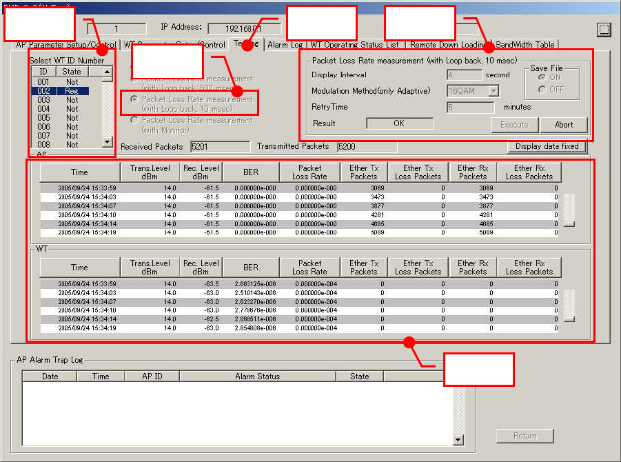
6-109
6.13.2. Measure the packet loss rate
Connect the OpS terminal to an AP and measure the packet loss rate with the following
procedure:
Step 1: Click the Testing tab.
Step 2: Select a WT from the Select WT ID list.
Step 3: Select the "Packet Loss Rate measurement (with Loop back, 10msec)" check
box.
Step 4: Specify the following settings, and click the Execute button to start the test.
- Display Interval : 4 seconds
- Modulation Method (only Adaptive) : Select the current modulation method
(check the WT Operation Status List in the OpS).
- Retry Time : 5 minutes
Step 5: Perform a time measurement and check the Packet Loss Rate column.
Figure 6-55 Measure the packet loss rate
Step 2
Step 1
Step 3
Step 4
Step 5

6-110
6.14. Check sheet of WT Construction
Check the operation of the WT using the check sheet below.
Test procedure
(A) LED operation test
- Remove the AC adapter (to turn off the power) and make sure that all the LEDs are off.
- Insert the AC adapter (to turn on the power) and check the states of the LEDs.
(B) Loopback test between the WT and the WT adapter
- Press the TEST switch on the WT adapter and make sure that the ETHER LED goes
out.
- Remove the cable from the WT adapter's PC port and make sure that the ETHER LED
goes out.
(C) Receive level
- Connect the WT Local Management Tool to the WT and measure the receive level.
(D) Position of the AP-RFU in the field of view after direction adjustment
- After the direction is adjusted, look into the scope of the Antenna direction adjustment
tool to visually check the position of the AP-RFU
Table 6-1 Check sheet
WT Serial number Test date
Test type Test condition Check item Pass/fail
Measured
value
Confirm that the POW LED on the WT adapter goes out.
-
Confirm that the ETHER LED on the WT adapter goes
out. -
Remove the AC
adapter.
Confirm that the ALM LED on the WT adapter goes out. -
Confirm that the POW LED on the WT adapter lights
green.
Confirm that the ETHER LED on the WT adapter flashes
green.
LED operation
test
Insert the AC
adapter.
Confirm that the ALM LED on the WT adapter flashes at
1-second intervals and then goes out.
Press the TEST
switch on the WT
adapter.
Confirm that the ETHER LED on the WT adapter goes
out. -
Loopback test
between WT and
WT adapter Remove the
cable from the
WT adapter's PC
port.
Confirm that the ETHER LED on the WT adapter goes
out.
Receive level − Connect the WT Local Management Tool to the WT and
measure the receive level. dBm
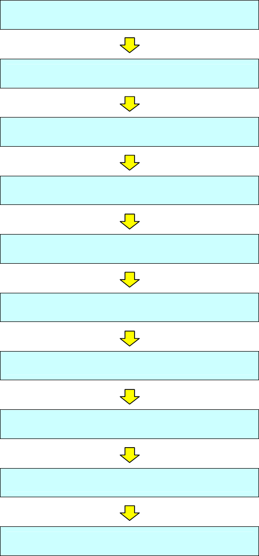
7-111
7. CONSTRUCTING A POINT-TO-POINT SYSTEM
7.1. Overview(WT Construction flow)
Connecting the WT Local Management Tool
Configure the WT(master)
Configure the WT(slave)
Installing the WT
Installing the WT Adapter(master/slave)
Connecting Cables to the WT(master/slave)
Waterproofing WT small window
Testing
Check sheet of Point to Point Construction
Finish
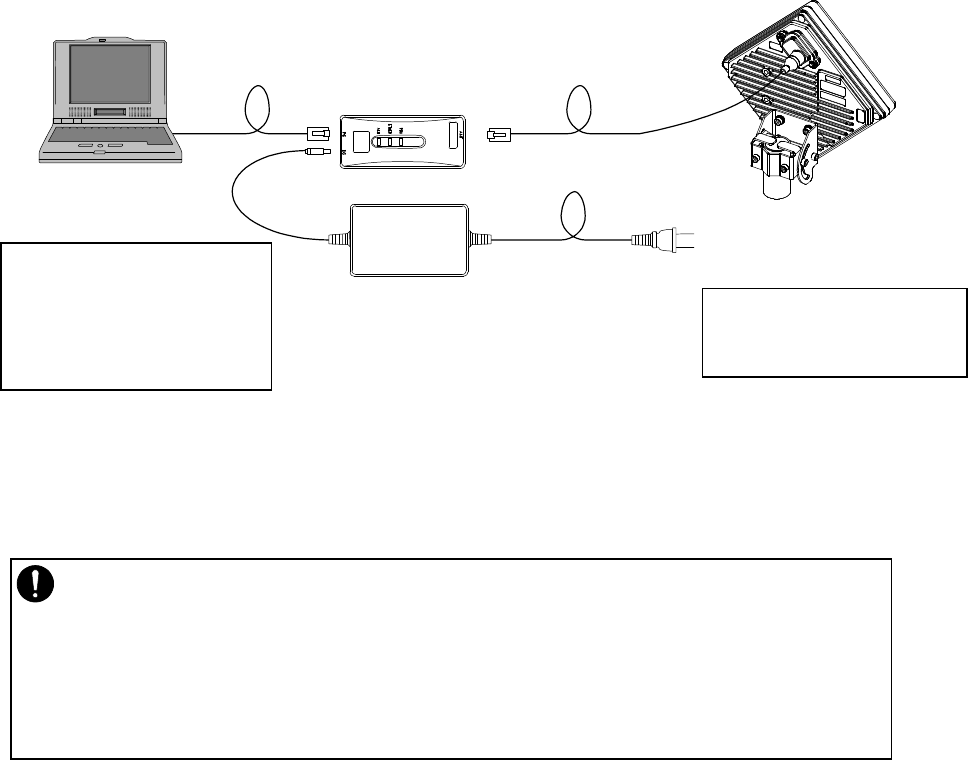
7-112
7.2. Connecting the WT Local Management Tool
Connect the local management tool terminal to the PC port of the WT adapter (Figure 7-1) using a
straight Ethernet cable.
Figure 7-1 Connection
Master
IP address: 192.168.1.200
Subnet mask: 255.255.255.0
Slave
IP address: 192.168.1.201
Subnet mask: 255.255.255.0
initial values
IP address:192.168.1.100
Subnet mask:255.255.255.0
Ethernet cable (Straight)
WT adapter
AC Adapter AC100∼240V
DC24V
local management tool(PC)
Ethernet cable (Straight)
・ When changing the IP addr
ess of the unit, set the IP address of the local
management tool (PC) to an IP address belonging to the same network.
・
When changing the IP address of the unit, restart the power of the hub if the unit is
connected to the local management tool (PC) via a hu
b (because MAC address
learning may fail and the connection may be dropped).
7-113
7.3. Configure the WT(master)
Change the WT’s mode from P-MP to P-P(matser).
On the Setup screen in the WT Local Management Tool (Master in P-P mode, Administrator),
specify the settings in the following procedure:
Step 1: Select the ”Master” setup tab.
Step 2: Specify the settings under Setup for Setup Parameters.
- System ID Number: Set the system ID number.
- Serial number at opposite WT: Set the serial number at the opposite WT.
- Encryption Parameter: Set the encryption parameter.
- Trans. Level: Set the transmission level.
- Modulation Method: Set the modulation method to QPSK, 16QAM, or AUTO.
- Interface Class: Set the interface class to AUTO or 10BASE.
- Radio Frequency: Set the radio frequency.
- Reg. Status: Set the registration status to Reg.
Step 3: Set the Network configuration for Setup Parameters.
- IP Address: Set the IP address.
- Subnet mask: Set the subnet mask.
- Default gateway: Set the default gateway.
- Trap Des. IP Add1: Set "Reg." or "Not" and trap destination IP address 1. As required,
you can also set Trap Des. IP Add2, and Trap Des. IP Add3.
- OpS Frame Priority: Set the OpS frame priority.
- OpS Frame Vlan-ID: Set the OpS frame Vlan-ID.
- ARP Request: Set the ARP request to ON or OFF.
Step 4: Click the Setup button.
Step 5 Make a clock setting in Setup Parameters2 and click the Setup button.
Step 6 Set RFU Transmission (Enable) in Setup Parameters3 and click the Execute button.
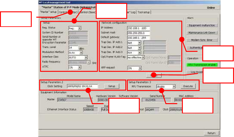
7-114
Figure 7-2 Configure the WT(master)
Step1
Step4
Step3
Step2
Step5
Step6
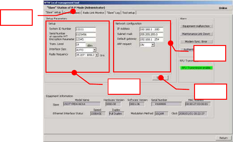
7-115
7.4. Configure the WT(slave)
Change the WT’s mode from P-MP to P-P(slave).
On the Setup screen in the WT Local Management Tool (Slave in P-P mode, Administrator),
specify the settings in the following procedure:
Step 1: Select the ”Slave” setup tab.
Step 2: Specify the settings under Setup for Setup Parameters.
- System ID Number: Set the system ID number.
- Serial number at opposite WT: Set the serial number at the opposite WT.
- Encryption Parameter: Set the encryption parameter.
- Trans. Level: Set the transmission level.
- Interface Class: Set the interface class to AUTO or 10BASE.
- Radio Frequency: Set the radio frequency.
Step 3: Set the Network configuration for Setup Parameters.
- AP IP Address: Set the AP IP address.
- Subnet mask: Set the subnet mask.
- Default gateway: Set the default gateway.
- ARP Request: Set the ARP request to ON or OFF.
Step 4: Click the Setup button.
Figure 7-3 Configure the WT(slave)
Step1
Step4
Step3
Step2
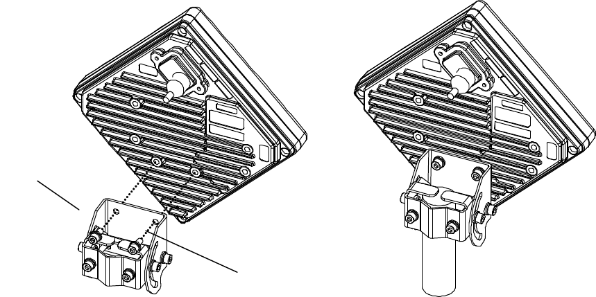
7-116
(a)
(b)
7.5. Installing the WT
7.5.1. Installing the WT(master/slave)
Step1 Attach the WT mounting bracket to the WT using the bolts(a)and (b).
You can orient the WT either for vertical or horizontal polarization.
Step2 Secure the WT mounting bracket to the pole using the bolts.
Applicable pole diameter: From Φ31.8mm to Φ34mm
Fi
gure 7-4 Installing the WT

7-117
A builder prepares a steel pipe by the installation place (a wall, a pole or etc.), and it install.
The required space of installation is shown below.
Figure 7-5 The required space of installation

7-118
7.5.2. Example of Installing the WT
(1) On a metal fence
Figure 7-6 Installing on a metal fence
(2) On a house wall
Figure 7-7 Installing on a house wall
MOUNTING
BRACKET
FIXING
BRACKET
METAL FENCE
WT
EAVES
WT
MOUNTING
BRACKET
FIXING
BRACKET
WALL
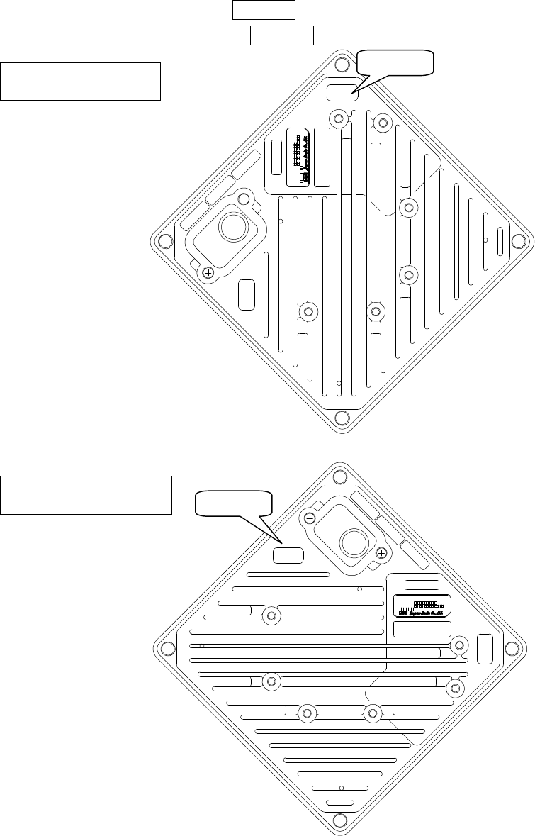
7-119
7.5.3. Setting the WT for Vertical or Horizontal Polarization
Rotate the antenna ninety degrees to choose between vertical or horizontal polarization
For vertical polarization, position TOP V at the top.
For horizontal polarization, position TOP H at the top.
Figure 7-8 Vertical Polarization
Figure 7-9 Horizontal Polarization
Horizontal polarization
TOP V
TOP H
ETHER
INPUT :
SER.NO :
MAC :
.:::::
MADE IN JAPAN
DC24V 0.7A
TYPEW−WT<EL0>
TOP H
Vertical polarization
TOP V
TOP H
ET H E R
INPUT :
SER.NO :
MAC :
.: : : : :
MADE IN JAPAN
TYPEW−WT<EL0>
DC24V 0.7A
TOP V

7-120
7.6. Installing the WT (External Antenna)
7.6.1. Installing the WT (ExternalΦ30cm Antenna)
1. Φ30cm antenna installation procedure
1) According to the antenna manual of RADIO WAVES, INC., set it up on the pole. (Figure 7-10)
2) Spread specified grease on the O-ring.
The spreading method depends on the
manual. (Figure 7-11)
Figure 7-10 Φ30cm antenna
Figure 7-11
2. WT installation procedure
Attach the antenna adaptor to the WT with the O-ring using four M3 screws. (Figure 7-12 & Figure 7-13)
Tightening torque:57 N・cm
Figure 7-12
M3 screws
O-ring
Adaptor
WT
O-ring
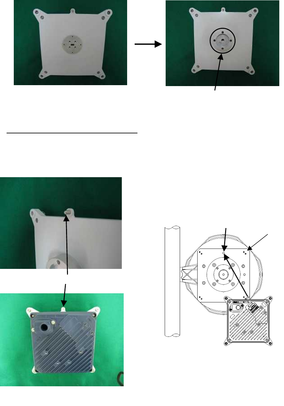
7-121
Figure 7-13
3. Attachment of the WT to the antenna
1) V(ertical) polarization
When using the V polarization, the guide pin of the WT should be turned to right above and inserted into
the V guide hole of the plate. (Figure 7-14 & Figure 7-15)
Figure 7-14
Figure 7-15
V polarization
Guide pin
I C: 76 8 B−N T G3 37 注 5
TOP V
T OP H
ET H ER
INPU T :
S E R . N O :
M A C :
.: : : : :
MADE IN JAP AN
DC2 4V 0.7A
TYPEW −W T < 注 1 >
FCCI D: C KENTG33 7 − 注 1
WT EL2
MODEL:NTG−337注2R
V guide hole
Plate
After installing the adaptor
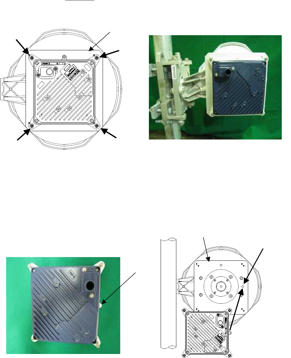
7-122
After inserting the guide pin of the WT into the guide hole, presses the WT to the plate.
While you are pressing the WT, you must be tightening the four M5 screws. (Figure 7-16)
Tightening torque:265 N・cm
Figure 7-16
2) H(orizontal) polarization
When using H polarization, the guide pin of the WT should be rotated to the right and inserted into the H
guide hole of the plate. (Figure 7-17 & Figure 7-18)
Figure 7-17 Figure 7-18
I C: 768B −NTG 33 7注5
T OPV
TOPH
ET HER
INPU T :
SER.NO :
M AC :
.: : :::
MADE IN JAPAN
DC24V 0 .7 A
T YPEW−WT<注1 >
F CCI D :C KENT G33 7 −注 1
WT E L2
MODEL:NTG−337注2R
Plate
M5 screws
Guide pin
IC:768B−NTG337注5
TOPV
TOP H
ETHER
IN P U T :
S E R . NO :
M A C :
.::: : :
MADE IN JAP AN
DC24V 0 .7A
TYP EW− W T < 注 1 >
F C CID:C KEN TG337 − 注 1
W T EL 2
MODEL:NTG−337注2R
Plate
H guide hole
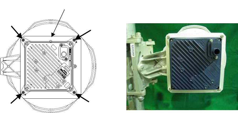
7-123
After inserting the guide pin of the WT into the guide hole, presses the WT to the plate.
While you are pressing the WT, you must be tightening the four M5 screws. (Figure 7-19)
Tightening torque:265 N・cm
Figure 7-19
I C:76 8B −NTG 337注5
TOP V
TOP H
ETHER
INPUT :
SE R .NO:
MAC :
.::: : :
M AD E INJAPAN
DC24V 0. 7 A
TY P EW−WT<注1 >
FCCI D:CKE N TG3 3 7−注 1
WT EL2
MO DE L : N TG− 3 3 7 注2R
Plate
M5 screws

7-124
7.6.2. Installing the WT (ExternalΦ60cm Antenna)
1. Φ60cm antenna installation procedure
1) According to the antenna manual of RADIO WAVES, INC., set it up on the pole. (Figure 7-20)
2) Spread specified grease on the O-ring.
The spreading method depends on the
manual. (Figure 7-21)
Figure 7-20 Φ30cm antenna
Figure 7-21
2. WT installation procedure
Attach the antenna adaptor to the WT with the O-ring using four M3 screws. (Figure 7-22 & Figure 7-23)
Tightening torque:57 N・cm
Figure 7-22
M3 screws
O-ring
Adaptor
WT
O-ring
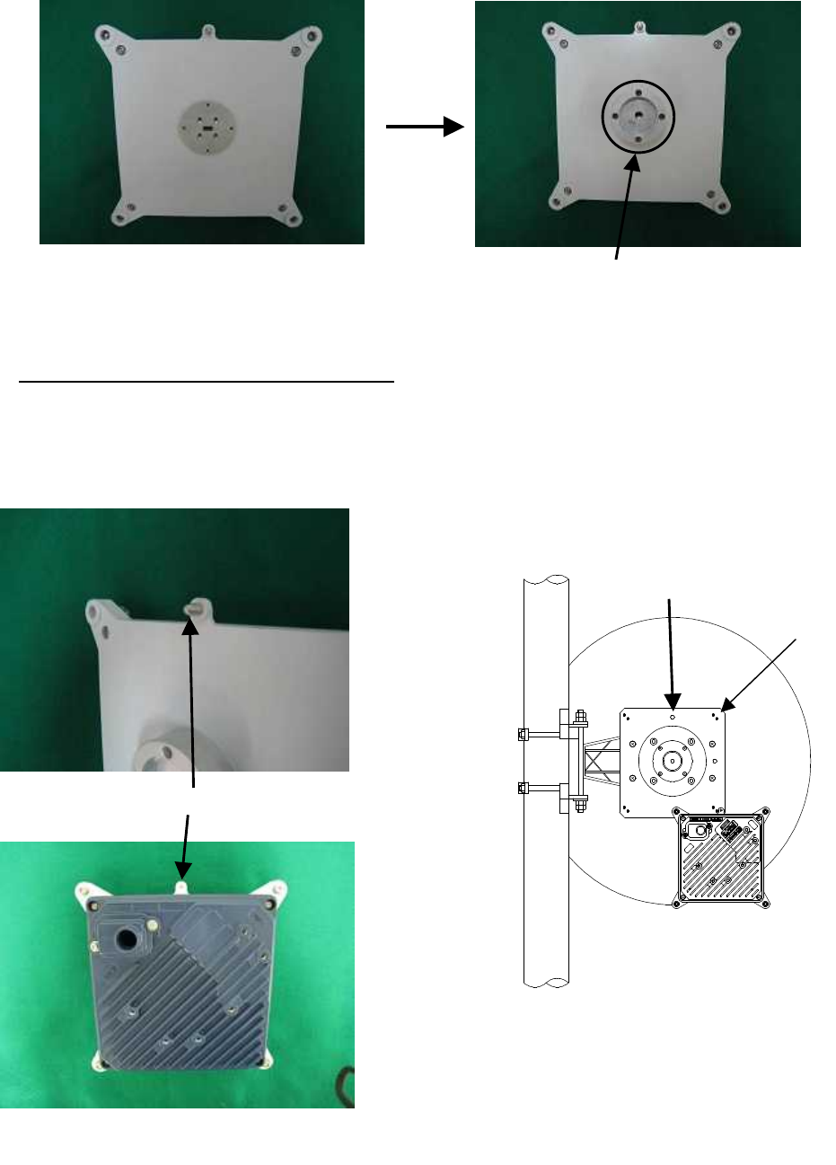
7-125
Figure 7-23
3. Attachment of the WT to the antenna
1) V(ertical) polarization
When using the V polarization, the guide pin of the WT should be turned to right above and inserted into
the V guide hole of the plate. (Figure 7-24 & Figure 7-25)
Figure 7-24
Figure 7-25
V polarization
Guide pin
After installing the adaptor
V guide hole
Plate
T OPV
TOP H
ETHER

7-126
After inserting the guide pin of the WT into the guide hole, presses the WT to the plate.
While you are pressing the WT, you must be tightening the four M5 screws. (Figure 7-26)
Tightening torque:265 N・cm
Figure 7-26
2) H(orizontal) polarization
When using H polarization, the guide pin of the WT should be rotated to the right and inserted into the H
guide hole of the plate. (Figure 7-27 & Figure 7-28)
Figure 7-27 Figure 7-28
Guide pin
Plate
M5 screws
TOP V
TO P H
ETHER
W T EL 2
Plate
H guide hole
TO P V
T O P H
E T H E R
W T EL 2
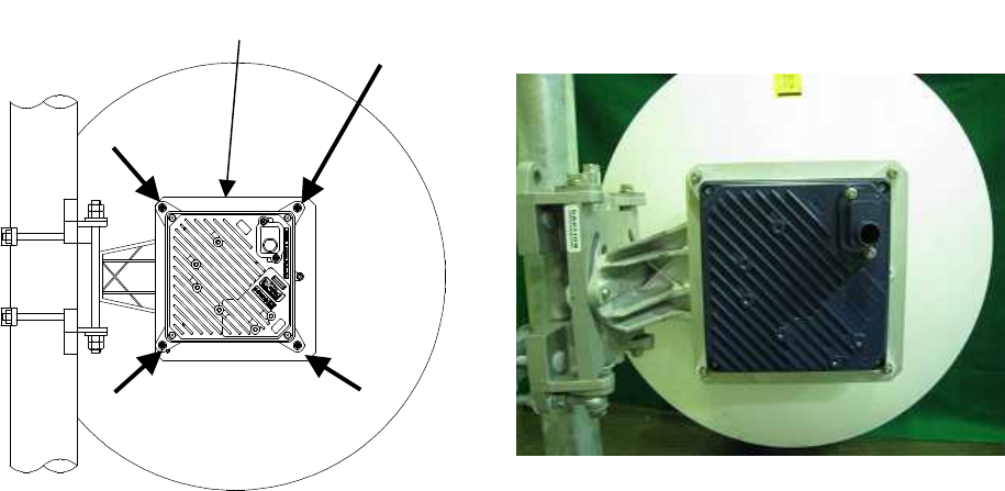
7-127
After inserting the guide pin of the WT into the guide hole, presses the WT to the plate.
While you are pressing the WT, you must be tightening the four M5 screws. (Figure 7-29)
Tightening torque:265 N・cm
Figure 7-29
Plate
M5 screws
TOPV
T OP H
ETHER
WT E L 2
7-128
7.7. Adjusting the Direction of the WT
7.7.1. Adjusting the Direction of the WT
This section describes the procedure for adjusting the antenna direction when a Point-to-Point
System is used.
When adjusting the direction of the WT antenna, use the “Antenna direction adjustment tool”
together with the WT Local Management Tool.
Step 1: Connection between WT (master/slave) and WT Local Management Tool and display the
Receiving Level.
See Subsection 7.7.1.1
- Method of adjustment for near-distance installation
If circuit design calls for a receive level of -35 dBm or higher, you need to reduce the
transmission level according to the following procedure:
WT (Master) Trans Level : 14dBm → -6dBm (see Subsection 7.7.1.1 (4))
WT (Slave) Trans Level : 14dBm → -6dBm (see Subsection 7.7.1.1 (4))
Step 2: Rough adjustment for the WT (Master)
- Install the Antenna direction adjustment tool.
- See Subsection 7.7.1.2
- Remove the Antenna direction adjustment tool.
Step 3: Rough adjustment for the WT (Slave)
- Install the Antenna direction adjustment tool.
- See Subsection 7.7.1.2
- Remove the Antenna direction adjustment tool.
Step 4: Fine adjustment for the WT (Slave)
- See Subsection 7.7.1.3
Step 5: Fine adjustment for the WT (Master)
- See Subsection 7.7.1.3
Step 6: Verification
- After fine adjustment, use the WT Local Management Tool to final check the receive level.
If the receive level value is within the standard range, the procedure for adjusting the
antenna direction has been completed.
If the receive level value is lower than a standard value, you need to perform Steps 4 and
5 again.
Step 7: Exit the WT Local Management Tool, and remove the cable from the WT adapter.
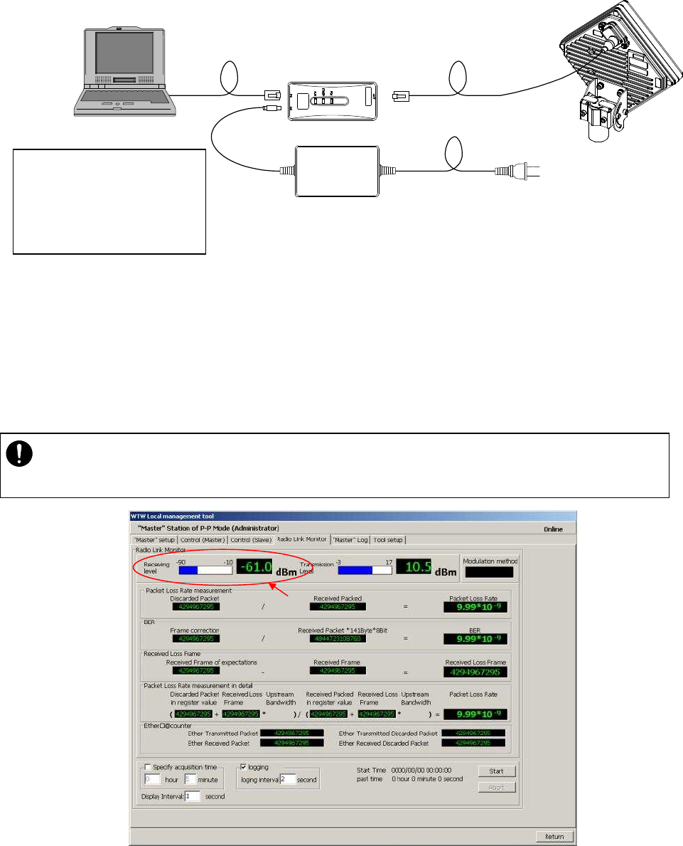
7-129
7.7.1.1. Connecting the WT Local Management Tool
(1) As shown in Figure 7-30, connect the WT Local Management Tool (PC) to the WT adapter.
Figure 7-30 Connecting the WT Local Management Tool
(2) Measuring the receive level the WT (master in P-P mode)
- Start the WT Local Management Tool and select P-P mode.
- On the Radio Link Monitor screen in the master station in P-P mode, measure the
"Receiving Level" value.
The procedure is shown in Figure 7-31.
Figure 7-31 Measuring the Receive Level (Master)
・ The minimum display interval is 1
second, and you need to adjust the antenna
direction slowly.
Master
IP address: 192.168.1.200
Subnet mask: 255.255.255.0
Slave
IP address: 192.168.1.201
Subnet mask: 255.255.255.0
WT adapter
AC Adapter AC100∼240V
DC24V
local management tool(PC)
Ethernet cable (Straight)
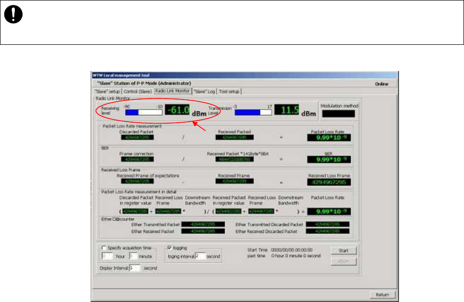
7-130
(3) Measuring the receive level of the WT (slave in P-P mode)
- Start the WT (slave in P-P mode) and select P-P mode.
- On the Radio Link Monitor screen in the slave station in P-P mode, measure the
"Receiving Level" value.
The procedure is shown in Figure 7-32.
Figure 7-32 Measuring the Receive Level (Slave)
・
The minimum display interval is 1 second, and you need to adjust the antenna
direction slowly.
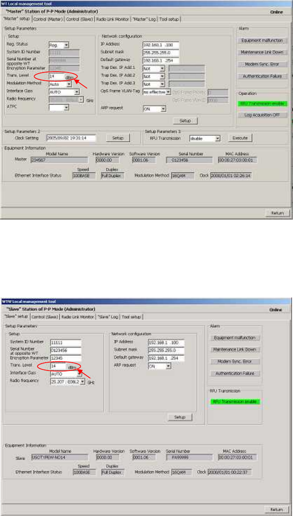
7-131
(4) Method of adjustment for near-distance installation
If circuit design calls for a receive level of -35 dBm or higher, use the following procedure:
- Start the WT Local Management Tool and select P-P mode.
- On the Master Setup screen in the master station in P-P mode, change "Trans.Level" from
14[dBm] to -6[dBm]. After the change, click the SETUP button.
The procedure is shown in Figure 7-33.
Figure 7-33 Setting "Trans.Level" for the WT (Master)
- On the Slave Setup screen in the slave station in P-P mode, change "Trans.Level" from
14[dBm] to -6[dBm]. After the change, click the SETUP button.
The procedure is shown in Figure 7-34.
Figure 7-34 Setting "Trans.Level" for the WT (Slave)
OFF
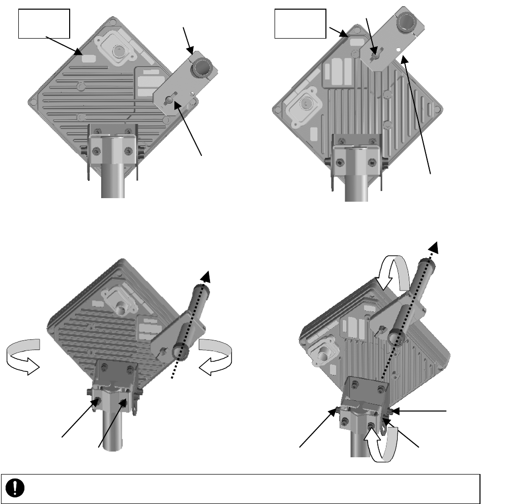
7-132
Direction adjustment tool
TOP V
(a)
TOP H
Direction adjustment tool
(a)
(f) (e)
(d)
(b) (C)
7.7.1.2. Roughly Adjusting the Direction
Step1 As shown inFigure 7-35 and Figure7-36, use the wing bolt (a) to attach the Antenna
direction adjustment tool.
Step2 As shown in Figure 7-37, loosen the hexagonal socket head bolts (b) and (c) securing the
mounting bracket and swing the antenna left or right. Adjust the antenna approximately for
the WT direction and finger-tighten the bolts (b) and (c).
Step3 As shown in Figure 7-38, loosen the bolts (d), (e), and (f) and tilt the antenna up or down.
Perform vertical-direction adjustment so that the WT of the opposite station can be seen
through the scope of the Antenna direction adjustment tool.
.
Figure 7-35 How to Install Direction Adjustment tool
when the antenna type is the horizontal polarization
Figure7-36 How to Install Direction Adjustment tool
when the antenna type is the vertical polarization
In Figure 7-37 and Figure 7-38 is an example when the antenna type is the horizontal polarization.
Figure 7-37 Rough-adjusting Horizontal Direction Figure 7-38 Rough-Adjusting the Vertical Direction
・ Never look at the sun directly. Doing so may seriously damage the eyes.
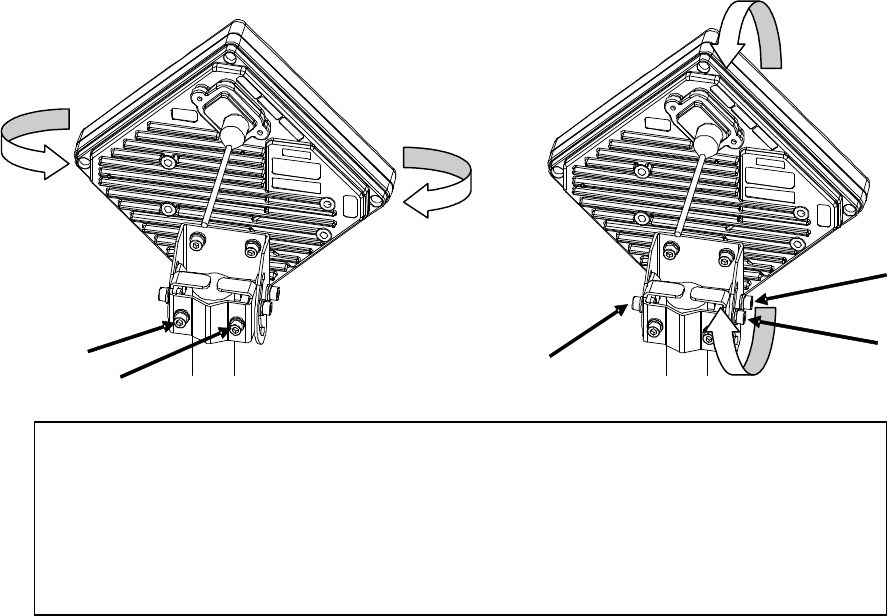
7-133
7.7.1.3. Finely Adjusting the Direction
Step 1: Horizontal direction
As shown in Figure 7-39, loosen the hexagonal socket head bolts (a) and (b) securing the
mounting bracket and swing the antenna left or right. Adjust the antenna direction so that the
receive level indicates the maximum value, and finger-tighten the bolts (a) and (b).
Step 2: Vertical direction
As shown in Figure 7-40, loosen the hexagonal socket head bolts (c), (d), and (e) securing the
mounting bracket and tilt the antenna up or down. Adjust the antenna direction so that the
receive level indicates the maximum value. Tighten the bolts at a point showing the maximum
receive level (tightening torque: 8.5N•m). Tighten the bolts (c), (d), and (e) and make sure that
the point showing the maximum receive level is maintained. This concludes the procedure for
vertical-direction adjustment.
Step 3: Horizontal direction
Finely adjust the horizontal direction by slightly loosening the bolts (a) and (b) again. Once
again, locate the point where the receive level reaches the maximum value and hold that point.
Finally, tighten the bolts (a) and (b) (tightening torque: 8.5N•m) while making sure that the
point showing the maximum receive level is maintained. This concludes the procedure for
horizontal-direction adjustment.
The figures show examples of horizontal polarization setup.
Figure 7-39 Finely Adjusting the Horizontal Direction Figure 7-40 Finely Adjusting the Vertical Direction
(a)
(b)
(d)
(c)
(e)
Note : When adjusting the antenna direction
When adjusting the direction, you m
ight mistakenly take the antenna's side lobe as
the maximum receive
level. For fine adjustment, therefore, you should move the
antenna some more after the receive level has reached the maximum value to make
sure that you have not caught a side lobe.
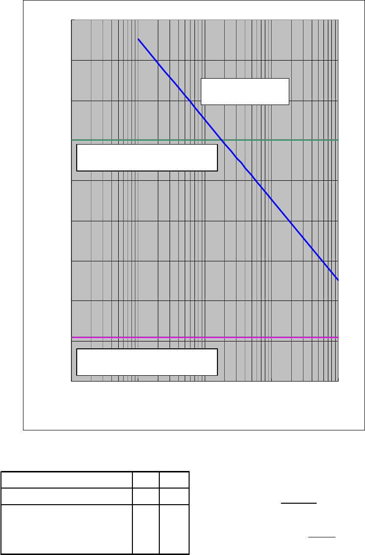
7-134
7.7.2. The receive level and the distance
In a point-to-point system, the receiving level at clear sky and the distance are related as shown in
Figure 7-41.
Figure 7-41 Receiving Level and Distance (QPSK)
-90
-80
-70
-60
-50
-40
-30
-20
-10
0
1 10 100 1000 10000
Distance[m]
Receiving Level [dBm]
Transmission level (QPSK) 14 [dBm] Free space loss Lp[dB]
Frequency 26 [GHz]
Antenna gain[TX+RX]
TX WT Antenna Gain:31dBiTYP
RX WT Antenna Gain:31dBiTYP
62 [dBi]
λ
πd
Lp 4
log20
Hzf
mc
mλ
Receiving level
Maximum receiving level
Minimum receiving level
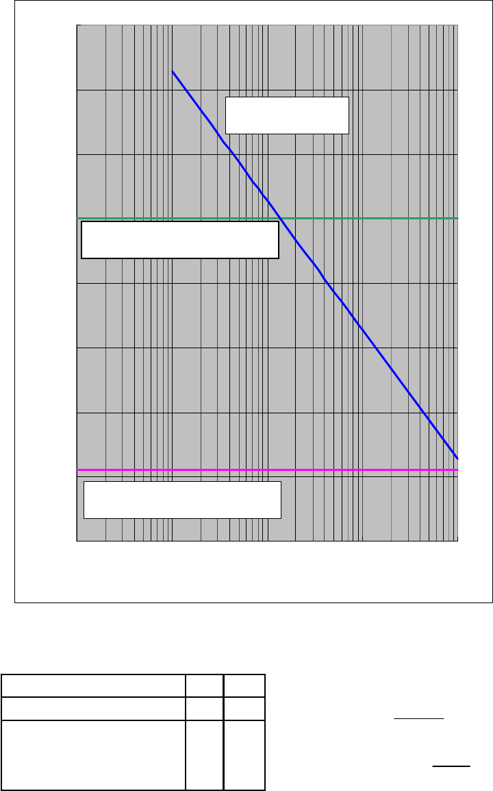
7-135
Figure 7-42 Receiving Level and Distance (16QAM)
-80
-70
-60
-50
-40
-30
-20
-10
0
1 10 100 1000 10000
Distance[m]
Receiving Level [dBm]
Transmission level (16QAM) 14 [dBm] Free space loss Lp[dB]
Frequency 26 [GHz]
Antenna gain[TX+RX]
TX WT Antenna Gain:31dBiTYP
RX WT Antenna Gain:31dBiTYP
62 [dBi]
λ
πd
Lp 4
log20
Hzf
mc
mλ
Maximum receiving level
Minimum receiving level
Receiving level
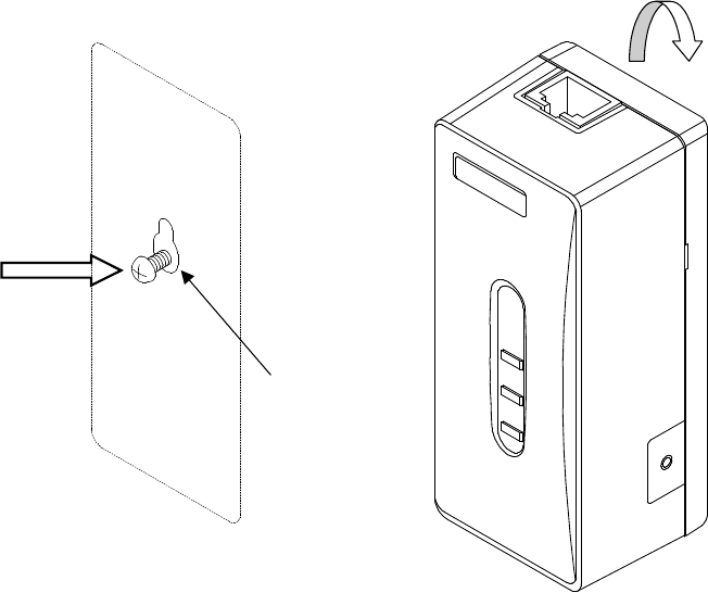
7-136
7.8. Installing the WT Adapter(master/slave)
WT Adapter is installed in indoor
It is an example of installing the appended wood screw.
Screw into the mounting position the wood screw that comes with the WT adapter, leaving 2 mm.
Hook the WT adapter on the wood screw.
Figure 7-43 Installing the WT Adapter on the Wall
Wood Screw

7-137
7.9. Connecting Cables to the WT(master/slave)
Use an Ethernet cable (straight) to connect the WT and the WT adapter as shown in Figure 7-44.
Figure 7-44 Connecting Cables to the WT
MDI
MDI-X
WT adapter
Cold-shrinkable tube
Small
Lid
Rubber
Ethernet cable (Straight)
You will need a Torx screwdriver (VESSEL
T20H-120) to open the small cover of the WT
AC adapter
User Terminal
WT
Cold-shrinkable tube
Spacer
Sm
all
Window
7-138
(1) Connected cable between WT and ANT port of WT adapter
(2) Connect the user terminal to PC port of WT adapter
(3) Connect the AC adapter to DC port to the WT adapter
Cable
Cable type Ethernet cable for outdoor,straight
Range of applicable outer
diameter φ5.0 mm∼5.7mm
Cable length 50m (maximum)
Connector of both side
Shape RJ-45
Cable connection Straight connection
- WT : MDI
- ANT port of WT adapter : MDI-X
An Ethernet cable has eight signal lines. Four lines are used to carry
Ethernet signals. The remaining four lines are used as power lines and
LED control lines.
Interface
Interface 10BASE-T/100BASE-TX
Connector
Shape RJ-45
Pin assign Ethernet signal(MDI-X)
Cable
Communication terminal Cable connection
PC straight
HUB crossover
ROUTER straight
・
Never connect your personal computer to the ANT port of the WT adapter. Doing so may
damage your personal computer.
・
The cable connecting between the WT and WT adapter carries 24 VDC for the WT in
addition to Ethernet signals. Before unplugging
the cable connecting between the WT and
WT adapter, make sure to unplug the DC jack of the WT adapter to turn the power off.
Otherwise, the unit may be damaged.
・
When closing the small window, make sure that the rubber packing of the small window is
free from any foreign matter.
・
The cable connecting the WT and WT adapter is a straight cable. Wrong connection may
damage the unit.
・ The Equipment for connection to WT adapter PC-interface(RJ-
45) shall be appropriate to
connect to TNV-1 circuits.
・ For the connecti
on WT adapter to WT and a cable suitable for outdoor use shall be
installed.
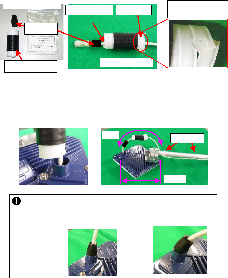
7-139
7.10. Waterproofing WT small window
(1) Pass the Ethernet cable through the cold-shrinkable tube (a) from the bonded portion of the
spiral tube. Pay attention to the insertion direction (Figure 7-46).
Applicable LAN cable diameter: 5.0 mm to 5.7 mm
Figure 7-45 Figure 7-46
(2) Connect the Ethernet cable to the WT (Figure 7-47).
(3) Using cable ties (c) or the like, secure the Ethernet cable to the supporting bracket. Attach the
cable ties 70 to 100 mm from the end of the supporting bracket. The cable is approximately
300 mm long measured from the cable joint (with a diameter of approximately 200 mm) to the
first cable tie (Figure 7-48).
Figure 7-47 Figure 7-48
・
Never allow the inside of the small window to become wet. Dampness may cause a
malfunction. Connect the Ethernet cable perpendicular to the WT. Failure to do so
will spoil the waterproofing effect, resulting in a device malfunction.
Bent cable
Cable perpendicular
to the WT
OK
(c Cable ties
φ200mm
300mm
(d) Spacer
(a) Cold-shrinkable tube
Pay attention to the irection
(b) Ethernet cable
Bonding portion of the spiral
tube for the cold-shrinkable
Components of CS sleeve
(e) Spiral tube
NG
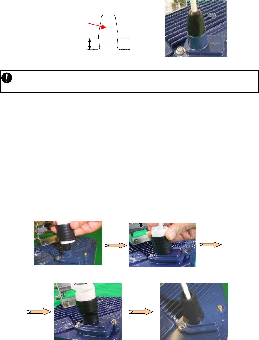
7-140
(4) Mounting spacer (d)
- Mount the spacer on the Ethernet cable
- Make sure that the spacer is fully inserted in the small Lid of the WT (Figure 7-50).
Figure 7-49 Figure 7-50
(5) Mounting cold-shrinkable tube (a)
- Place the cold-shrinkable tube on the spacer and small Lid (Figure 7-51).
- Butt the end of the cold-shrinkable tube against the base of the small Lid. Pulling white
spiral tube (e) to the very edge of the cold-shrinkable tube eases the subsequent
procedure (Figure 7-51).
- Pull the spiral tube to mount the edge of the cold-shrinkable tube on the small Lid (Figure
7-52). Make sure that there is no gap between the cold-shrinkable tube and the base of
the small Lid and between the spacer and the small Lid.
- Pull the spiral tube to mount the cold-shrinkable tube, paying attention so the spacer is
not lifted (Figure 7-53 and Figure 7-54). Make sure that the spacer is not protruded from
the cold-shrinkable tube. The top of the cold-shrinkable tube should be 5 mm or less from
the top of the spacer.
Figure 7-51 Figure 7-52
Figure 7-53 Figure 7-54
(d)
Inserted
Spacer
・
Insert the spacer into the small window fully. Partial insertion of the spacer will spoil the
waterproofing effect.
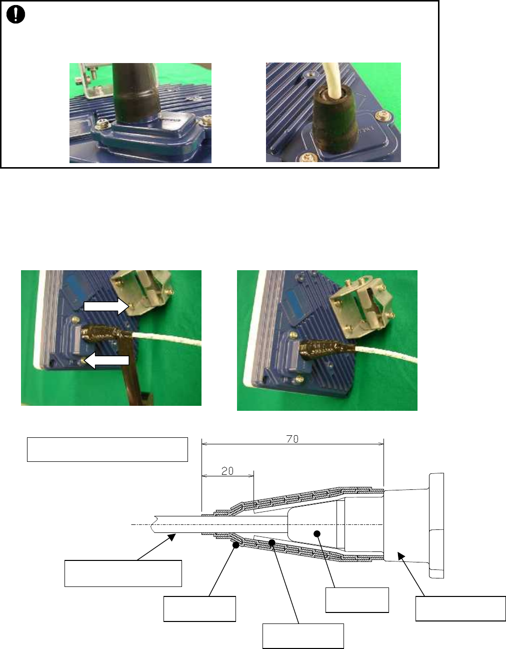
7-141
Length of PVC tape wrapping
Small window
(6) Wrap the cable with PVC tape (for class 2 protection).
Apply the PVC tape so that the cold-shrinkable tube is completely hidden. Wrap the tape from
the small Lid of the WT to the Ethernet cable, overlapping half of the previous layer. Next,
reverse the wrapping direction and wrap one more time to the starting point.
・ Slanted mounting of the cold-
shrinkable tube as shown below will spoil the
waterproofing effect. If the top of the cold-
shrinkable tube is 5 mm or less from the
top of the spacer, this will also spoil the waterproofing effect.
NG
NG
Ethernetcable cable
Spacer
CS sleeve
PVC tape
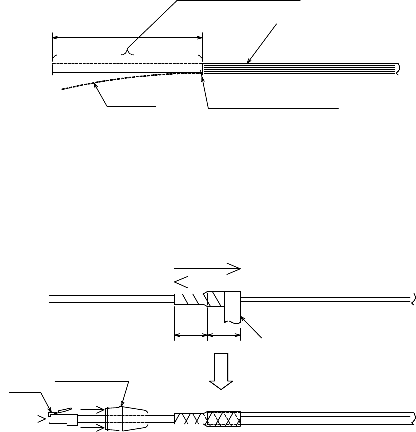
7-142
7.11. When you use the cable with the LAP sheath for outdoor
1.Processing of LAP sheath
- The LPA sheath is peeled off from the cable point to 120mm.
- It cuts it in the part peeled off when there is drain wire.
2.Processing of cutting part
- To prevent water being infiltrated in the wire, the self-bonding tape is rolled in the part
where the LAP sheath was peeled off as shown in the figure below.
- The Ether plug is installed with the normal temperature shrinkage sleeve and Spasa
passed.
3.Fixation of cable Ethernet、Installation of Spacer and normal temperature shrinkage sleeve
- See「6.9. Waterproofing WT small window」
4.Wrapping of PVC tape for protection
- It wraps until the self-bonding tape in the LAP sheath processing part is completely hidden
120mm
The cable with the LAP sheath
Drain
wire
is cut on the LAP sheath side.
Drain Wire
50mm
25
25
Self-bonding
Spacer
Connector
Push
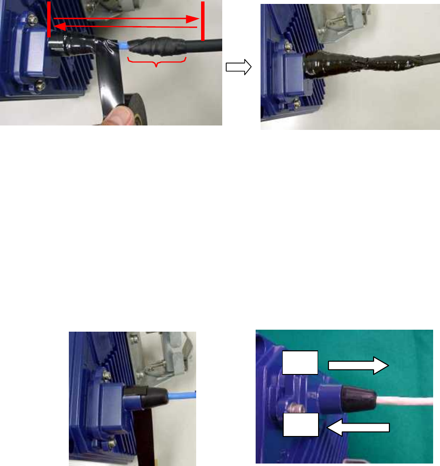
7-143
from a small window to the Ethernet cable side by 1/2 coming in succession, and 1 return
round trip to the small window side.
7.12. Waterproofing Without Using a Cold-Shrinkable Tube
If installing a cold-shrinkable tube fails, use off-the-shelf self-bonding tape to provide the
waterproofing.
(1) Securing the small Lid of the WT and the spacer
Using an appropriate length of self-bonding tape, wrap the tape around both the small Lid of
the WT (at its base) and spacer one complete turn. After one turn, wrap about seven turns
around the Ethernet cable by overlapping one-half of the previous turn. Reverse the wrapping
direction and wrap about another seven turns back to the small Lid.
START
END
Self-bonding tape part
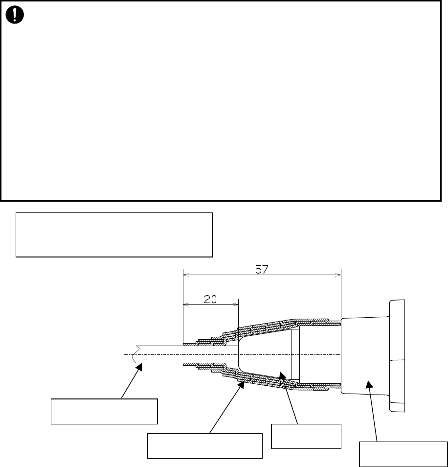
7-144
(2) Wrapping protective PVC tape
Apply the protective PVC tape so that the cold-shrinkable tube is completely hidden. Wrap the
tape from the small Lid of the WT to the Ethernet cable, overlapping half of the previous layer.
Next, reverse the wrapping direction and wrap one more time to the starting point. Using the
PVC tape will guard the self-bonding tape against ultraviolet and other rays. The wrapping
also helps increase strength.
Key point: When wrapping PVC tape, be sure that the self-bonding tape is completely covered
for its protection.
・ For the stretching margin of self-bon
ding tape, see the instruction manual for the
product.
・ When wrapping self-
bonding tape, start at the base of the small window and end at
the end of the waterproof sleeve. Next, reverse the direction and end at the base of
the small window. This procedure m
akes an attractive wrapping and improves the
waterproof effect by making any air pocketsless likely.
・ Overlapping the wraps also protects against air pockets.
・ Press evenly along the entire length of tape to remove air pockets.
・ Make sure that there are no air pockets between the self-
bonding tape and the small
window of the WT or the rubber bushing. Air pockets will degrade the waterproofing
effect.
Overlapping half og the previous layer
(cross-sectional view)
Ethernet cable
Spacer
Small window
Self-bonding tape
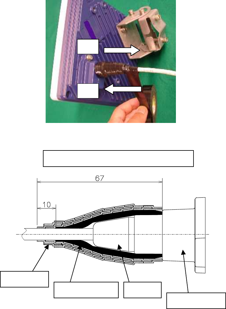
7-145
START
END
PVC tape
Self- bonding tape
Spacer
Small window
Length of PVC tape used for wrapping
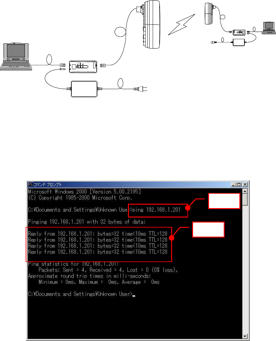
7-146
7.13. Testing
7.13.1. Ping test
Connect the WT and the PC as shown in Figure 7-55. Use the PC to perform a ping test in the
following procedure.
WT adapter
AC Adapter AC100∼240V
DC24V
PC Ethernet cable (Straight)
Master Slave
Figure 7-55 Ping Test System Diagram
Step 1: Start the Windows command prompt.
Step 2: Type the following command and press the Return key.
Ping xxx.xxx.xxx.xxx, where xxx.xxx.xxx.xxx shows the IP address of the
opposite PC.
Step 3: After the command is run, check that a reply as shown in Figure 7-56 returns.
Figure 7-56 Ping Test
Step 2
Step 3
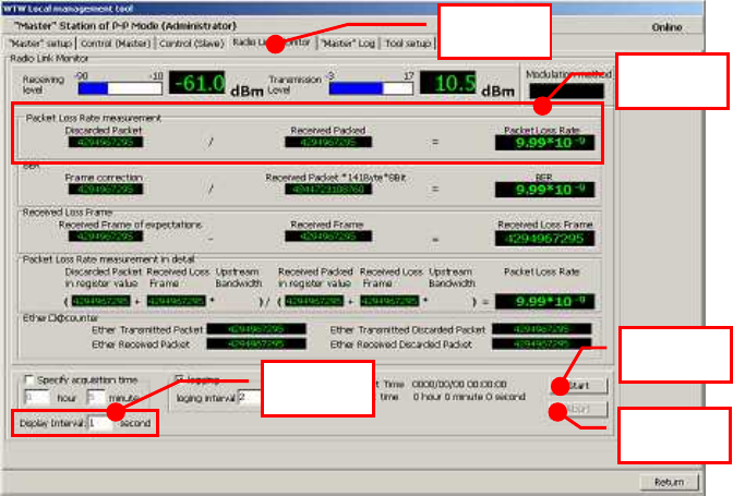
7-147
7.13.2. Measure the packet loss rate (with WT Local
mnagement tool)
Connect the WT Local Management Tool and measure the packet loss rate in the following
procedure:
Step 1: Start the WT Local Management Tool and select P-P mode.
Step 2: Select the Radio Link Monitor tab.
Step 3: Set "Display Interval" to 1.
Step 4: Click the Start button to start traffic measurement.
Step 5: After traffic measurement for any length of time, click the Abort button to end
traffic measurement.
Step 6: Check "Packet Loss Rate."
Figure 7-57 Measure the packet loss rate
Step4
Step2
Step3
Step5
Step6
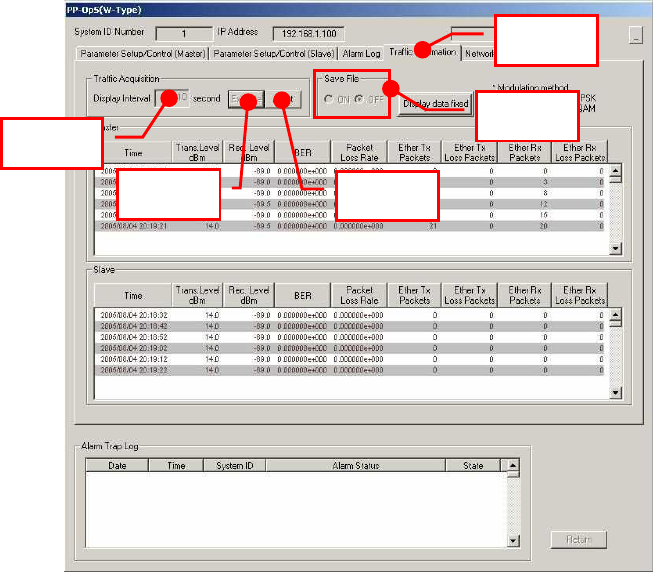
7-148
7.13.3. Measure the packet loss rate (with OpS)
Connect the OpS terminal to the WT (Master) and measure the packet loss rate in the following
procedure.
Step 1: Select the Traffic Information tab.
Step 2: Set "Display Interval" under "Traffic Acquisition."
Step 3: Select Save File as ON or OFF.
Step 4: Click the Execute button under "Traffic Acquisition" to start traffic measurement.
Step 5: After traffic measurement for any length of time, click the Abort button under
"Traffic Acquisition" to end traffic measurement.
Step 6: Check "Packet Loss Rate."
Figure 7-58 Measure the packet loss rate
Step 2
Step 1
Step 3
Step 4
Step 5

7-149
7.14. Check sheet of Point to Point Construction
Check operation of the WT (Master/Slave) using the check sheet below.
Test procedure
(A) LED operation test
- Remove the AC adapter (to turn off the power) and make sure that all the LEDs go out.
- Insert the AC adapter (to turn on the power) and check the states of the LEDs.
(B) Loopback test between the WT and the WT adapter
- Press the TEST switch on the WT adapter and make sure that the ETHER LED goes
out.
- Remove the cable from the WT adapter's PC port and make sure that the ETHER LED
goes out.
(C) Receive level
- Connect the WT Local Management Tool to the WT and measure the receive level.
Table 7-1 Check sheet
WT Serial number Test date
Test type Test condition Check item Pass/fail
Measured value
Confirm that the POW LED on the WT adapter goes out.
-
Confirm that the ETHER LED on the WT adapter goes
out. -
Remove the AC
adapter.
Confirm that the ALM LED on the WT adapter goes out. -
Confirm that the POW LED on the WT adapter lights
green.
Confirm that the ETHER LED on the WT adapter flashes
green.
LED operation
test
Insert the AC
adapter.
Confirm that the ALM LED on the WT adapter flashes at
1-second intervals and then goes out.
Confirm that the ETHER LED on the WT adapter goes
out. -
Loopback test
between WT and
WT adapter Press the TEST
switch on the WT
adapter.
Confirm that the ETHER LED on the WT adapter goes
out.
Receive level Remove the
cable from the
WT adapter's PC
port.
Connect the WT Local Management Tool to the WT and
measure the receive level. dBm

8-150
8. Standard Tools to be Used
The table below lists the tools used during installation or maintenance of the units.
Table 8-1 Tools Used
No.
Unit
name Used for: Tightening
torque [N•cm]
Tool
1 Door M5 265 Torx driver (VESSEL T25H-120)
2 Power board M4 127 Phillips screwdriver
3 Cable clamp M4 118 Phillips screwdriver
4
Ground M4 nut
127 Socket driver (Width across flats: 7)
5
AP-IFU
SC lock(cap) G3/8
nut 110 to 150 Spanner wrench (Width across flats:
22)
6 Small window M4 127 Torx driver (VESSEL T20H-120)
7 Mounting bracket M6 850 Allen wrench (Width across flats: 5)
8
WT
Ethernet cable Crimping tool for RJ-45
(Release-after-crimp type)
9 AP-RFU
(Omni) Mounting bracket
axis tightening M6
M16 850
9410 Socket wrench (Width across flats:
24)
10
AP-RFU
(Sectoral-
Horn)
Mounting bracket M6 850 Allen wrench (Width across flats: 5)
The appropriate tightening torque is 10% of the value indicated in the table.

9-151
9. INITIAL VALUES
9.1. Point to Multipoint system
The factory-set initial values for a point-to-multipoint system are shown below.
9.1.1. Initial values for AP parameters (Point to Multipoint System)
Table 9-1 shows the AP initial values.
Table 9-1 Initial values for AP parameters
Parameter which can be
set up
Parameters Initial values Setting range Local
manageme
nt tool PMP-OpS
Registerd in AP-RFU memory
AP transmission level 14 +14 invalid valid
RFU transmission state disable disable/enbale invalid valid
Radio frequency Not registered Depends on the content of the
registration of “ini FILE” valid invalid
Registerd in AP-IFU memory
AP ID number 0 0∼65535 invalid valid
AP registration status Not registered Registered/Not registerd invalid valid
Upstream arbitration bandwidth 2 1∼8
(Total bandwidth corresponds
to 10)
invalid valid
OpS frame VLAN priority 4 0∼7 valid invalid
User frame VLAN priority 0 0∼7 valid invalid
OpS frame VLAN-ID 0 2∼4094 valid invalid
Modulation method Mixed QPSK/16QAM/Mixed invalid valid
IP addrss 192.168.0.1 0.0.0.0∼255.255.255.255 valid invalid
Subnet mask 255.255.255.0
0.0.0.0∼255.255.255.255 valid invalid
Default gateway 192.168.0.254
0.0.0.0∼255.255.255.255 valid invalid
Trap destination 1 status Registered Registered
/Not registered valid valid
Trap destination IP address 1 192.168.0.2 0.0.0.0∼255.255.255.255 valid valid
Trap destination 2 status Not registered Registered
/Not registered valid valid
Trap destination IP address 2 192.168.0.3 0.0.0.0∼255.255.255.255 valid valid
Trap destination 3 status Not registered Registered
/Not registered valid valid
Trap destination IP address 3 192.168.0.4 0.0.0.0∼255.255.255.255 valid valid

9-152
Trap destination 4 status Not registered Registered
/Not registered invalid valid
Trap destination IP address 4 192.168.0.5 0.0.0.0∼255.255.255.255 invalid valid
Trap destination 5 status Not registered Registered
/Not registered invalid valid
Trap destination IP address 5 192.168.0.6 0.0.0.0∼255.255.255.255 invalid valid
Trap destination 6 status Not registered Registered
/Not registered invalid valid
Trap destination IP address 6 192.168.0.7 0.0.0.0∼255.255.255.255 invalid valid
Trap destination 7 status Not registered Registered
/Not registered invalid valid
Trap destination IP address 7 192.168.0.8 0.0.0.0∼255.255.255.255 invalid valid
Trap destination 8 status Not registered Registered
/Not registered invalid valid
Trap destination IP address 8 192.168.0.9 0.0.0.0∼255.255.255.255 invalid valid
Trap destination 9 status Not registered Registered
/Not registered invalid valid
Trap destination IP address 9 192.168.0.10 0.0.0.0∼255.255.255.255 invalid valid
Trap destination 10 status Not registered Registered
/Not registered invalid valid
Trap destination IP address 10 192.168.0.11 0.0.0.0∼255.255.255.255 valid invalid
Ether-IF 1 Active Active/Non-active valid invalid
Ether-IF 2 Non-active Active/Non-active valid invalid

9-153
9.1.2. Initial values for WT(1 - 239) parameters (Point to Multipoint
system)
Table 9-2 Initial values for WT(1 - 239) parameters (Point to Multipoint system)
Parameter which can be
set up
Parameters Initial
values Setting range Local
manageme
nt tool PP-OpS
Registerd in AP-IFU memory
WT serial number All space ASCII: 7 characters invalid
(Only
display) valid
Authentication parameter All space ASCII: 10 characters invalid
(Only
display) valid
VLAN-tag control Non
transparent
Non transparent
/transparent
invalid
(Only
display) valid
Interface class AUTO AUTO/10BASE invalid
(Only
display) valid
9.1.3. Initial values for VID(2 - 4094) table parameters (Point to
Multipoint system)
Table 9-3 Initial values for VID(2 - 4094) table parameters (Point to Multipoint system)
Parameter which can be set up
Parameters Initial
values Setting range
Local
management
tool PP-OpS
Registerd in AP-IFU memory
WT ID number 0 0∼239 invalid
(Only display)
valid
Service status Out of
service
Out of
service
/In service
invalid
(Only display)
valid

9-154
9.1.4. Initial values for AP-IFU swiches
Table 9-4 Initial values for AP-IFU swiches
Iteme Initial values
ETHER1 AUTO/100FULL SW 100FULL
ETHER2 AUTO/100FULL SW 100FULL
.

9-155
9.1.5. Initial values for WT(Master) parameters (Point to point System)
Table 9-5 lists the WT defaults set in the factory.
Parameter which can be set
up
Parameters Initial values Setting range WT Local
management
tool PP-OpS
1
Registered information
Not registered Registration/Not registration valid valid
2
System ID number 0 1-65535 valid valid
3
Opposite-station serial
number 11 blank characters
7 single-byte alphanumeric
characters valid invalid
4
Encryption parameter
10 blank characters
5 single-byte alphanumeric
characters valid invalid
5
Send level 14dBm -6 - +14dBm valid valid
6
Modulation method 16QAM 16QAM/QPSK/AUTO(reserved) valid valid
7
Interface AUTO AUTO/10BASE valid invalid
8
Radio frequency Not set Based on the registered ini file valid invalid
9
Master ATPC OFF OFF/ON valid valid
10
IP ADDRESS 192.168.1.100 0.0.0.0 - 255.255.255.255 valid invalid
11
Subnet mask 255.255.255.0 0.0.0.0 - 255.255.255.255 valid invalid
12
Default gateway 192.168.1.254 0.0.0.0 - 255.255.255.255 valid invalid
13
Trap destination 1 to
10 0.0.0.0 0.0.0.0 - 255.255.255.255 valid
(only 1 - 3 ) valid
14
VLAN tag OFF OFF/ON valid invalid
15
OpS VID 0 1 -4094 valid invalid
16
OpS priority 0 0 - 7 valid invalid
17
ARP response ON ON/OFF valid invalid
18
Disable transmission OFF ON/OFF valid valid
19
Slave ATPC OFF OFF/ON valid valid
20
Read community name
public 10 single-byte characters valid invalid
21
Write community name
public 10 single-byte characters valid invalid
22
Trap community name
public 10 single-byte characters valid invalid

9-156
9.1.6. Initial values for WT (Slave) parameters (Point to point System)
Table 9-6 lists the WT defaults set in the factory.
Setting tool
Parameters
Initial values Setting range WT Local management
tool PP-OpS
1
System ID number 0 1-65535 valid invalid
2
serial number at
Opposite WT 11 blank characters
7 single-byte
alphanumeric
characters valid invalid
3
Encryption parameter
10 blank characters
5 single-byte
alphanumeric
characters valid invalid
4
Transmit level 14dBm -6 - +14dBm valid invalid
5
Interface class AUTO AUTO/100BASE valid invalid
6
Radio frequency Not set Based on the
registered ini file valid invalid
7
IP ADDRESS 192.168.1.100 0.0.0.0 -
255.255.255.255 valid invalid
8
Subnet mask 255.255.255.0 0.0.0.0 -
255.255.255.255 valid invalid
9
Default gateway 192.168.1.254 0.0.0.0 -
255.255.255.255 valid invalid
10
ARP response ON ON/OFF valid invalid
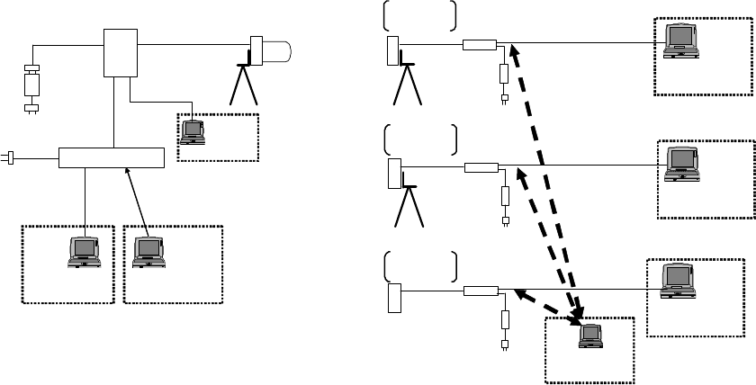
10-157
10. System example Point to Multipoint system
An example point-to-multipoint system configuration is shown in Figure 10-1.
The settings of this system configuration are as follows:
AP setting: Table 10-1
WT setting: Table 10-2
VLAN switch setting: Figure 10-2
RFU
IFU-RFU Cable
DC-48V Cable
DC-48V
Connector
L2SW
LAN Cable
LAN Cable
LAN Cable
OpS PC Test PC
LAN Cable WT Adapter
AC Adapter
LAN Cable
tripod
tripod
WT1
LAN Cable WT Adapter
AC Adapter
LAN Cable
tripod
LAN Cable WT Adapter
AC Adapter
Test PC
Test PC
IFU
Management Cable
(Serial Cable)
IP :192.168.2.100
Sub:255.255.255.0
IP :192.168.0.120
Sub:255.255.255.0
IP :192.168.0.1
Sub:255.255.255.0
IP :192.168.2.101
Sub:255.255.255.0
IP :192.168.2.102
Sub:255.255.255.0
VID:2
non-transparent
IP:192.168.1.100
WT2
AC-DC
Converter
AC100∼240V
TypeA or TypeC
AC100∼240V
TypeA or TypeC
AC100∼240V
TypeC
AC100∼240V
TypeC
AC100∼240V
TypeC
Maintenance Tool
WT2WT3
OpS
Maintenance Tool
IP :192.168.1.101
Sub:255.255.255.0
VID:50
non-transparent
IP:192.168.1.100
WT3 VID:100
non-transparent
IP:192.168.1.100
WT1
Test PC
IP :192.168.2.103
Sub:255.255.255.0
LAN Cable
only Setup
Figure 10-1 System example Point to Multipoint

10-158
Table 10-1 Setup parameters AP(Point to Multipoint)
AP
Item Value Tool
OpS Frame Priority 4 Management Tool
User Frame Priority 0 Management Tool
OpS Frame Vlan-ID 500 Management Tool
AP IP address 192.168.0.1 Management Tool
Subnet mask 255.255.255.0 Management Tool
Default gateway 192.168.0.254 Management Tool
Trap Des. IP1 192.168.0.120 Management Tool
Trap Des. IP2 non-Reg Management Tool
Trap Des. IP3 non-Reg Management Tool
Ether-IF1 Active Management Tool
Ether-IF2 non-Active Management Tool
Radio frequency Management Tool
AP ID number 1 OpS
Upstream Arbi.BW 2 OpS
AP Trans. Level 14 OpS
AP Reg. Status Reg OpS
RFU Transmission Enable OpS
Modulation Method Mixed OpS

10-159
Table 10-2 Setup parameters WT(Point to Multipoint)
WT WT1 WT2 WT3
Item Value Value Value Tool
WT ID Number 1 2 3 Management Tool
AP ID Number 1 1 1 Management Tool
Encryption
Parameter 1234567890 0987654321 9876543210 Management Tool
Select WT ID
number 1 2 3 OpS
VLAN-TAG Cont non-transparent
non-transparent non-transparent
OpS
Authen. Param 1234567890 0987654321 9876543210 OpS
Serial number
(example) NJJW000011T NJJW000012T NJJW000013T
OpS
WT Reg. Status Reg Reg Reg OpS
Modulation Method
adaptive adaptive adaptive OpS
Interface Class Auto Auto Auto OpS
RFU Transmission
Enable Enable Enable OpS
VLAN-ID 2 50 100 OpS
VLAN-ID
Registration Status
Reg Reg Reg OpS
Out of Service / In
Service In Service In Service In Service OpS
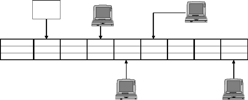
10-160
Point to Maltipoint VLAN SW parameters
PortNumber 1 2 3 4 5 6 7 8
tag type tagged untag untag untag untag untag untag untag
VID Number Default Default 2 50 100 200 300 500
OpS PC
In case of connecting
with WT1's TestPC
In case of connecting
with WT2's TestPC
AP IFU
L2 SW
In case of connecting
with WT3's TestPC
AP's TestPC
AP's TestPC
AP's TestPC
Figure 10-2 Point to Maltipoint VLAN SW parameters
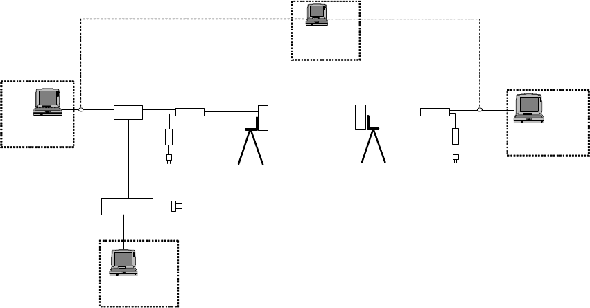
11-161
11. System example Point to Point
An example point-to-point system configuration is shown in Figure 11-1.
The settings of this system configuration are as follows:
setting: Table 11-1
VLAN switch setting: Figure 11-2
L2SW
LAN Cable
OpS PC
LAN Cable
WT Adapter
AC Adapter
LAN Cable
tripod
WT1
Master
LAN Cable WT Adapter
AC Adapter
LAN Cable
tripod
Test PC
IP :192.168.1.120
Sub:255.255.255.0
IP :192.168.2.101
Sub:255.255.255.0
WT2
Slave
AC100∼240V
TypeA or TypeC
AC100∼240V
TypeC
AC100∼240V
TypeC
Test PC
IP :192.168.2.100
Sub:255.255.255.0
IP :192.168.1.101
Sub:255.255.255.0
Maintenance PC
IP :192.168.1.100
Sub:255.255.255.0 IP :192.168.1.100
Sub:255.255.255.0
LAN Cable
LAN
Cable
SW-HUB
Figure 11-1 System example Point to Point

11-162
Table 11-1 Setup parameters WT(Master) / WT(Slave) (Point to Point)
WT1 (Master) WT2 (Slave)
Item Value Value Tool
System ID number 11111 11111 Management Tool
Encryption Parameter
12345 12345 Management Tool
Sireal No. Management Tool
Trans. level 14 14 Management Tool
OpS Fra. Praiority 0 - Management Tool
OpS Fra. Vlan-ID 500 - Management Tool
IP address 192.168.1.100 - Management Tool
Subnet mask 255.255.255.0 - Management Tool
Default gateway 192.168.1.254 - Management Tool
Trap Des. IP Add.1 192.168.1.120 - Management Tool
Trap Des. IP Add.2 non-Reg - Management Tool
Trap Des. IP Add.3 non-Reg - Management Tool
Interface Class AUTO - Management Tool
Reg. Status Registered - Management Tool
RFU Transimission Enable - Management Tool /OpS
Radio frequency Management Tool
ATPC off off Management Tool
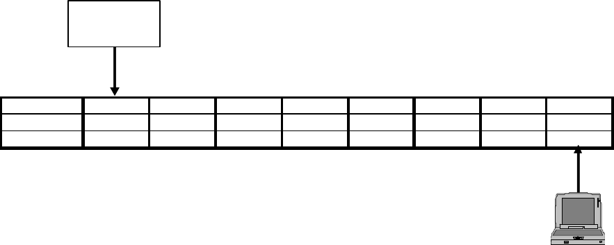
11-163
Point to Point VLAN SW parameters
PortNumber 1 2 3 4 5 6 7 8
tag type tagged untag untag untag untag untag untag untag
VID Number Default Default 2 50 100 200 300 500
OpS PC
WT1 adapter
Master
L2 SW
Figure 11-2 Point to Point VLAN SW parameters

11-164
 ̄ ̄ ̄ ̄ ̄ ̄ ̄ ̄ ̄ ̄ ̄ ̄ ̄ ̄ ̄ ̄ ̄ ̄ ̄ ̄ ̄ ̄ ̄ ̄
JRC FWA SYSTEM
Instruction Manual
H-7YZCM0101B
Rev. 3.4
24/SEP./2008
 ̄ ̄ ̄ ̄ ̄ ̄ ̄ ̄ ̄ ̄ ̄ ̄ ̄ ̄ ̄ ̄ ̄ ̄ ̄ ̄ ̄ ̄ ̄ ̄