Japan Radio NTG337-XL2 User Station User Manual Manual Part 2
Japan Radio Co Ltd. User Station Manual Part 2
UserManual.wiki
>
Japan Radio
>
NTG337-XL2 User Manual
>
Manual Part 2
Contents
1.
Manual
2.
Manual Part 2
Manual Part 2
Navigation menu
Upload a User Manual
Namespaces
Wiki Guide
HTML
PDF
Info
Views
User Manual
Discussion / Help
Navigation
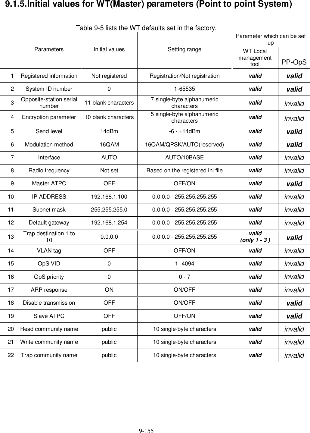
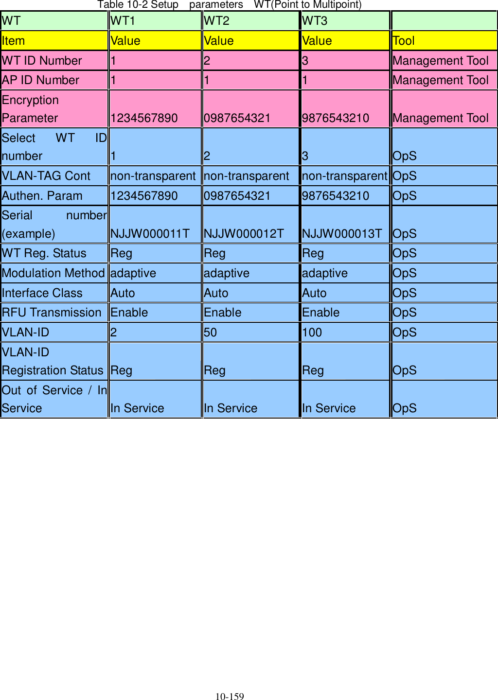
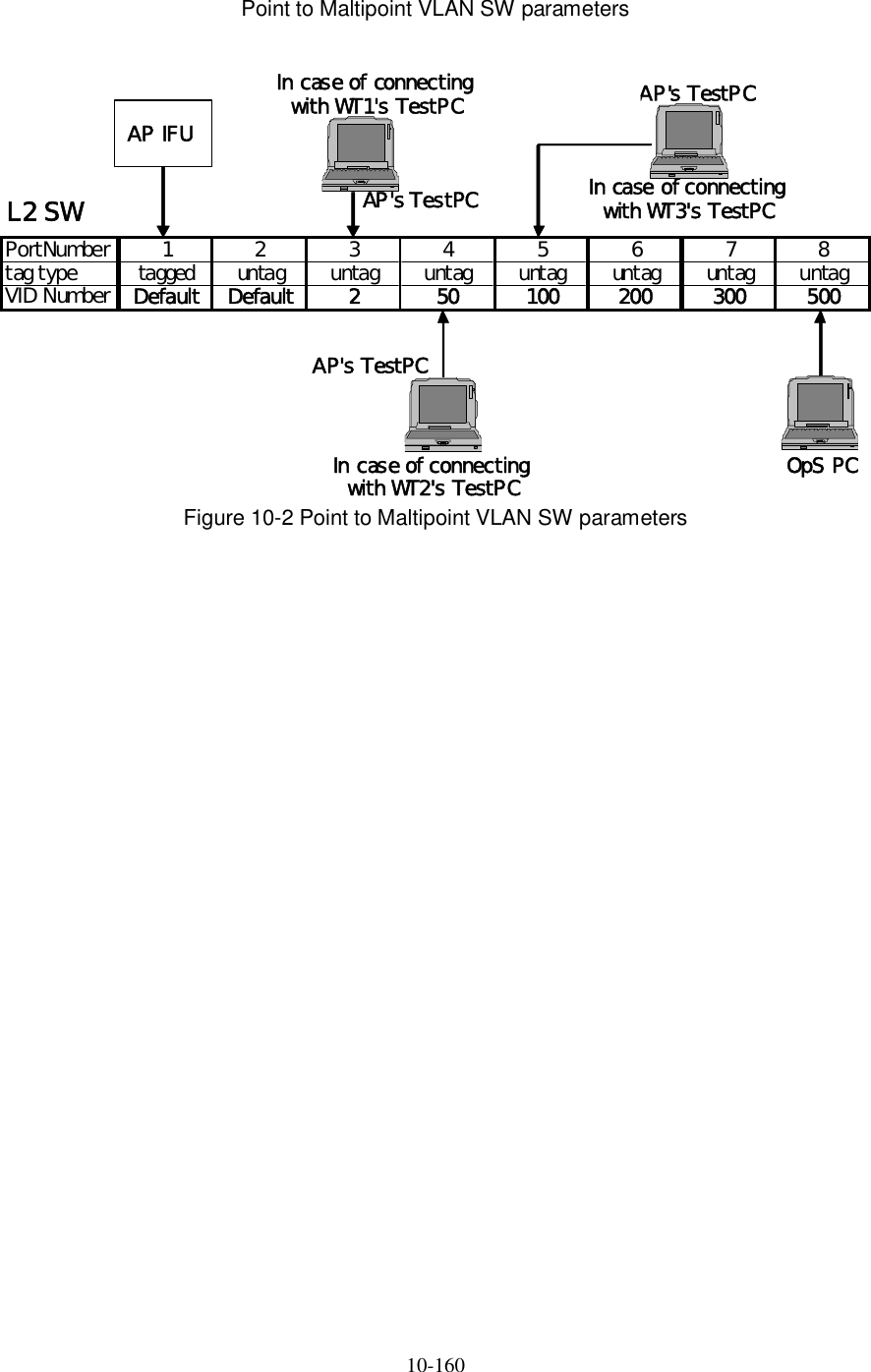
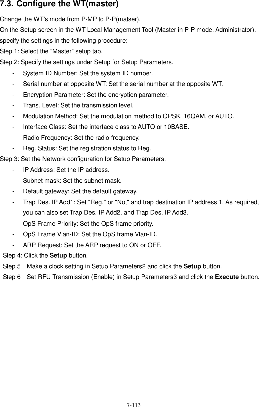
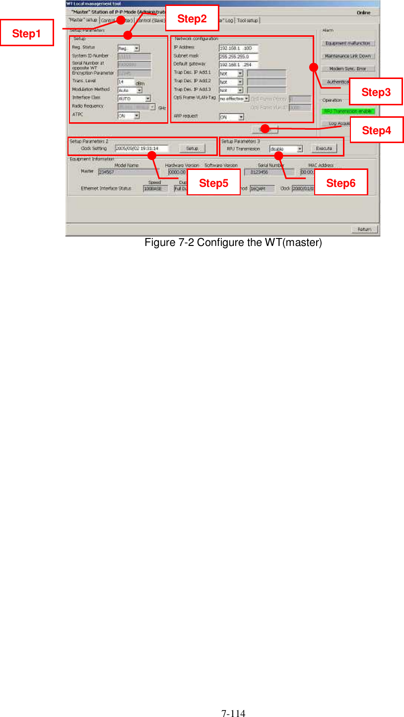
![6-74 6.2. OpS 6.2.1. Register the WT ID number to AP Connect the OpS to the target AP and register a WT. Step 1: In the OpS, select the WT Parameter Setup/Control tab. Step 2: Select the WT from "Select WT ID number." Step 3: Specify the setup parameters. - VLAN-TAG Cont: Set the VLAN-TAG Cont to Transparent. - Authen Param: Set the authentication parameter. - Serial number: Set the serial number and click the Set button. - WT Reg. Status: Set the WT registration status to Registered and click the Set button. - Modulation: Set the modulation to QPSK, 16QAM, or Adaptive and click the Set button. - Interface Class: Set the interface class to AUTO or 10BASE and click the Set button. - RFU Transmission: Set the RFU Transmission to Enable and click the Execute button. The following dialog box appears since a value is already set for "RFU Transmission." Click the OK button. - UP Stream Bandwidth table [Maximum Limit / Minimum Guarantee] - Down Stream Bandwidth table [Maximum Limit / Minimum Guarantee] Clicking the Set button displays a dialog box. Place checkmarks in the checkboxes and click the Set button. Step 4: Set the VLAN-ID. - VLAN-ID: Set the VLAN-ID and click the Register button. - Since the VLAN-ID that has been set appears on the screen, select it. - VLAN-ID Registration status: Set the VLAN-ID registration status to Registered. - Service status [ out of service / In service ] : Set the Service status to In service](https://usermanual.wiki/Japan-Radio/NTG337-XL2.Manual-Part-2/User-Guide-1044923-Page-2.png)
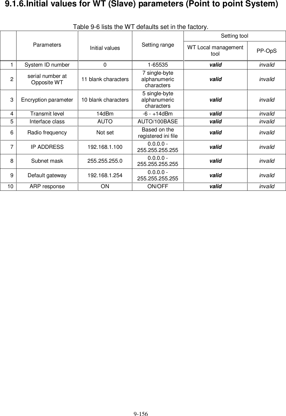
![6-75 Figure 6-1 Register the WT ID number to AP Step1 Step2 Step3 Step4 Set Bandwidth table Select [Parameter setup/control] tab Select the WT ID number set parameters Set VLAN-ID](https://usermanual.wiki/Japan-Radio/NTG337-XL2.Manual-Part-2/User-Guide-1044923-Page-3.png)


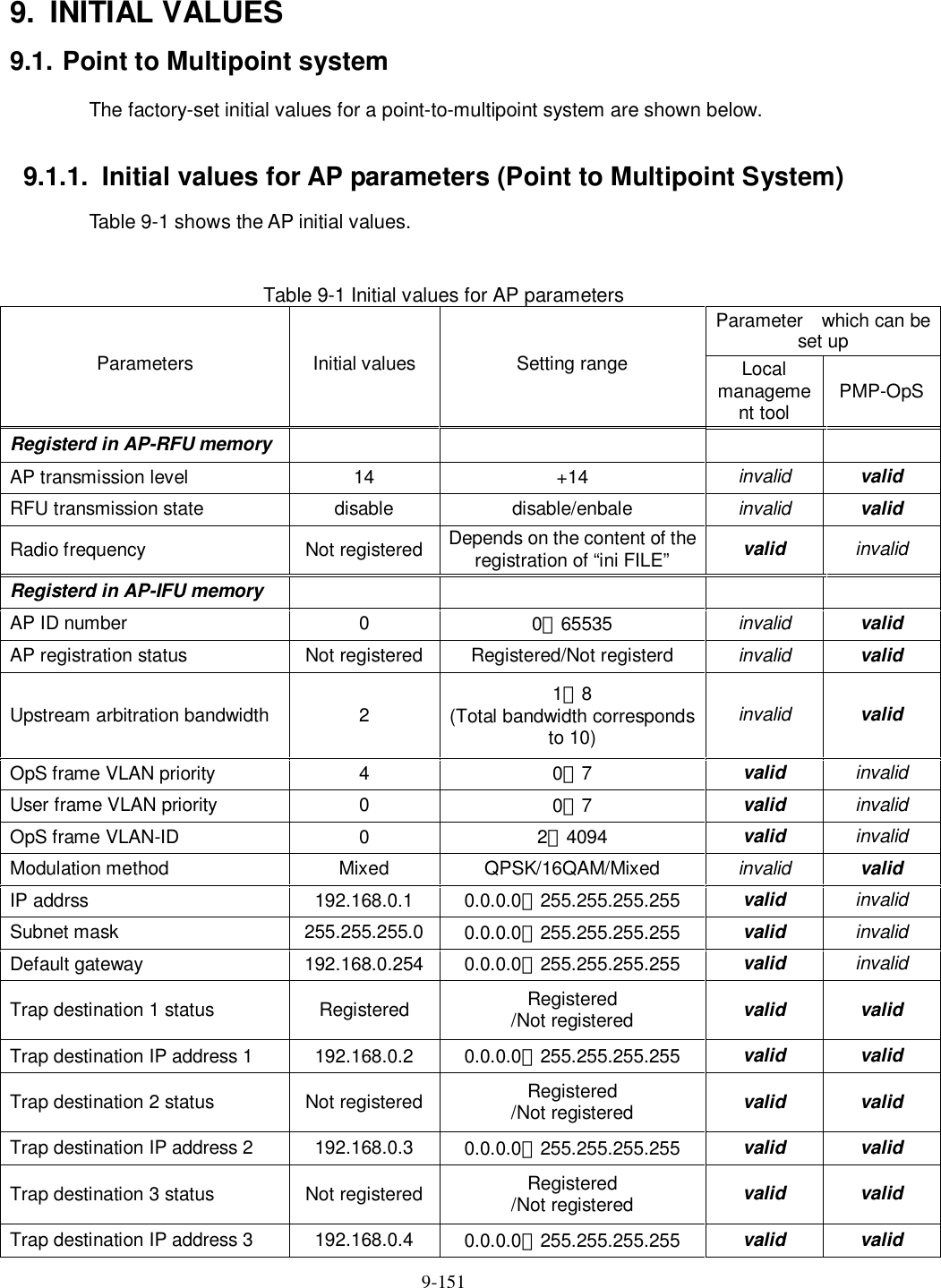
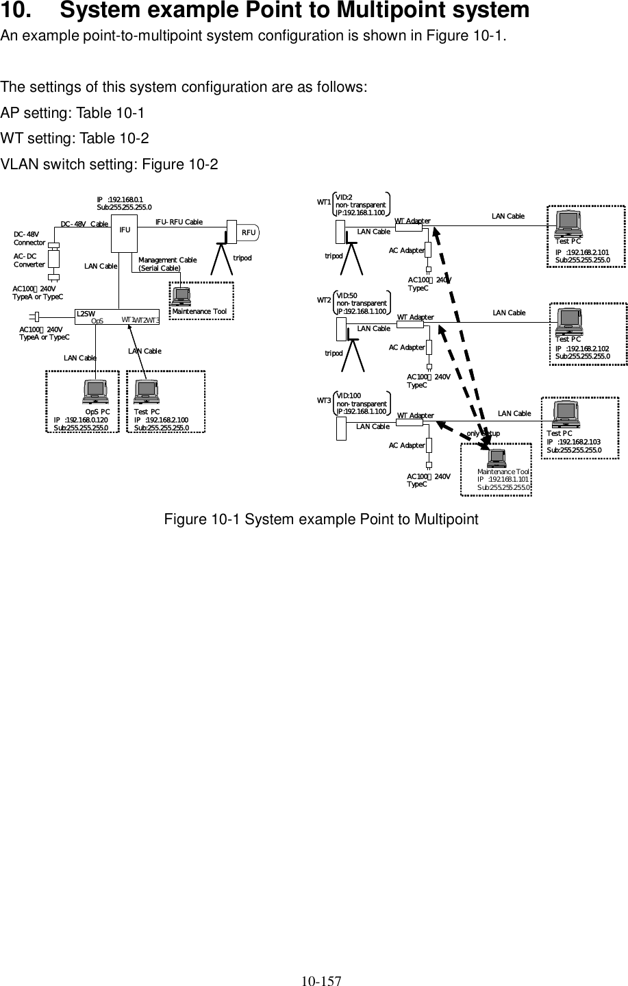
![6-93 6.7.4. The receive level and the distance For the receiving AP-RFU (Sectoral-Horn Antenna) in a point-to-multipoint system, the receiving level at clear sky and the distance are related as shown in Figure 6-38. Figure 6-38 Receiving Level and Distance (Sectoral QPSK) -90-80-70-60-50-40-30-20-1001 10 100 1000 10000Distance[m]Receiving Level [dBm]Maximum Receiving Level WT Receiving Level AP Receiving Level Minimum Receiving Level Transmission level (QPSK) 14 [dBm] Free space loss Lp[dB]Frequency 26 [GHz]Antenna gain[TX+RX]TX Sectoral Antenna Gain:15.5dBiTYPRX WT Antenna Gain:31dBiTYP46.5 [dBi] λπdLp 4log20 Hzfmcmλ](https://usermanual.wiki/Japan-Radio/NTG337-XL2.Manual-Part-2/User-Guide-1044923-Page-21.png)
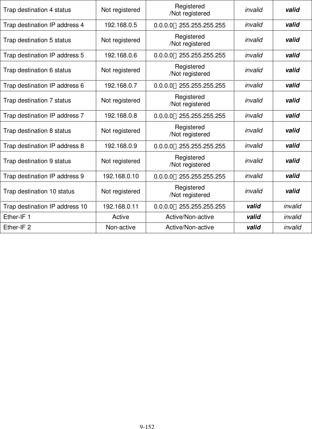
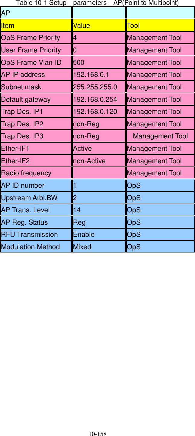
![6-94 Figure 6-39 Receiving Level and Distance (Sectroral 16QAM) -90-80-70-60-50-40-30-20-1001 10 100 1000 10000Distance[m]Receiving Level [dBm]Transmission level (QPSK) 11.5 [dBm] Free space loss Lp[dB]Frequency 26 [GHz]Antenna gain[TX+RX]TX Sectoral Antenna Gain:15.5dBiTYPRX WT Antenna Gain:31dBiTYP46.5 [dBi] λπdLp 4log20 HzfmcmλWT Receiving Level Maximum Receiving Level AP Receiving Level Minimum Receiving Level (16QAM)](https://usermanual.wiki/Japan-Radio/NTG337-XL2.Manual-Part-2/User-Guide-1044923-Page-22.png)
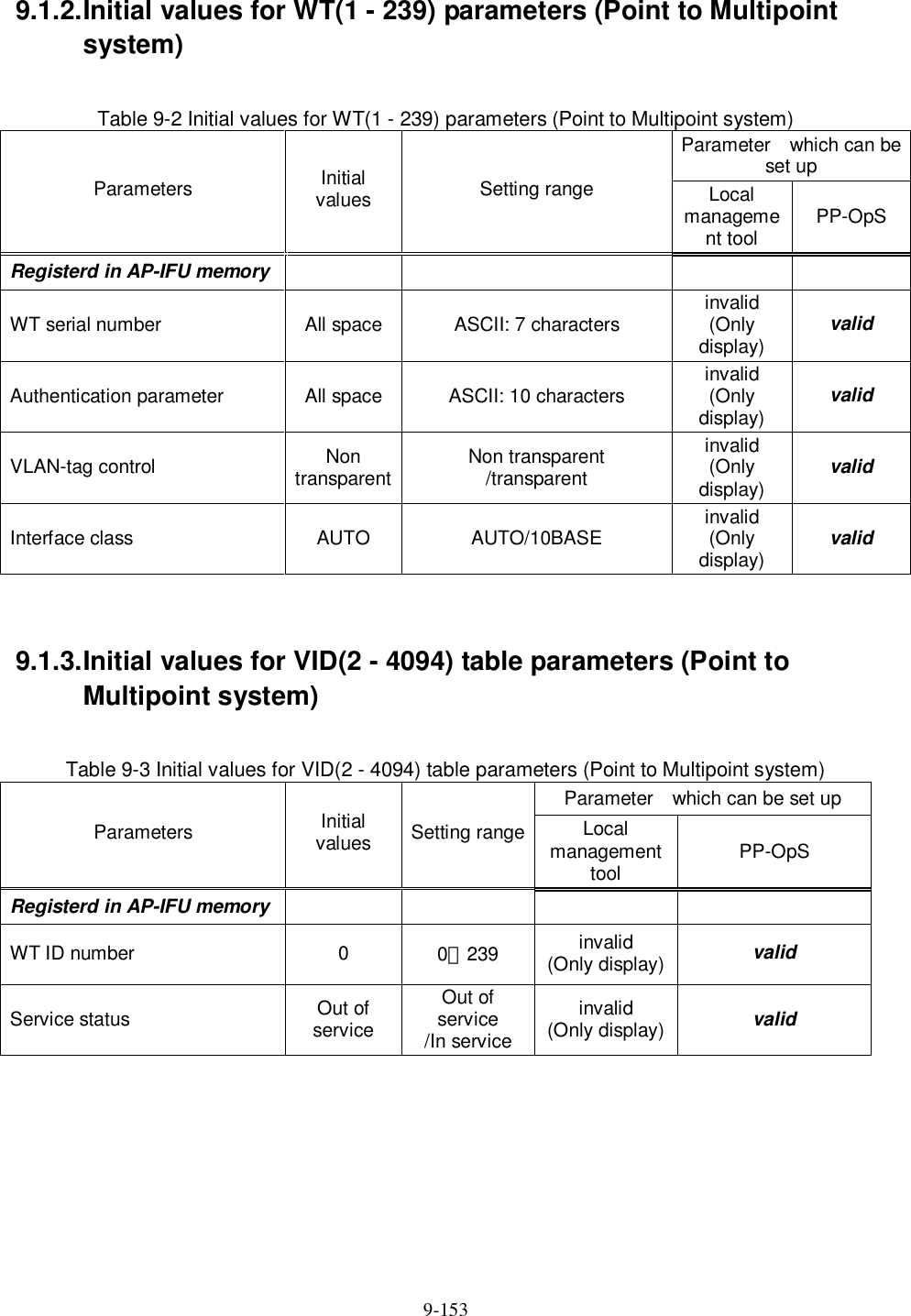
![6-95 Figure 6-40 Receiving Level and Distance (Omni QPSK) -90-80-70-60-50-40-30-20-1001 10 100 1000 10000Distance[m]Receiving Level [dBm]Transmission level (QPSK) 14 [dBm] Free space loss Lp[dB]Frequency 26 [GHz]Antenna gain[TX+RX]TX Sectoral Antenna Gain:6.5dBiTYPRX WT Antenna Gain:31dBiTYP37.5 [dBi] λπdLp 4log20 HzfmcmλMaximum Receiving Level AP Receiving Level Minimum Receiving Level WT Receiving Level](https://usermanual.wiki/Japan-Radio/NTG337-XL2.Manual-Part-2/User-Guide-1044923-Page-23.png)
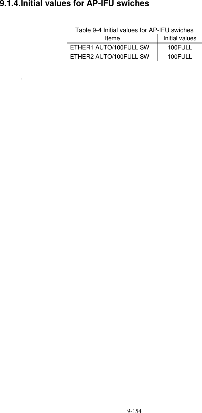
![6-96 Figure 6-41 Receiving Level and Distance (Omni 16QAM) -90-80-70-60-50-40-30-20-1001 10 100 1000 10000Distance[m]Receiving Level [dBm]Transmission level (QPSK) 11.5 [dBm] Free space loss Lp[dB]Frequency 26 [GHz]Antenna gain[TX+RX]TX Sectoral Antenna Gain:6.5dBiTYPRX WT Antenna Gain:31dBiTYP37.5 [dBi] λπdLp 4log20 Hzfmcmλ(16QAM) WT Receiving Level Maximum Receiving Level AP Receiving Level Minimum Receiving Level](https://usermanual.wiki/Japan-Radio/NTG337-XL2.Manual-Part-2/User-Guide-1044923-Page-24.png)
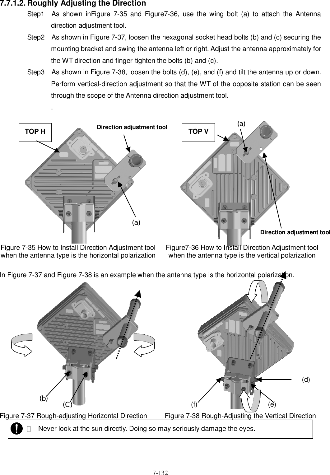
![7-131 (4) Method of adjustment for near-distance installation If circuit design calls for a receive level of -35 dBm or higher, use the following procedure: - Start the WT Local Management Tool and select P-P mode. - On the Master Setup screen in the master station in P-P mode, change "Trans.Level" from 14[dBm] to -6[dBm]. After the change, click the SETUP button. The procedure is shown in Figure 7-33. Figure 7-33 Setting "Trans.Level" for the WT (Master) - On the Slave Setup screen in the slave station in P-P mode, change "Trans.Level" from 14[dBm] to -6[dBm]. After the change, click the SETUP button. The procedure is shown in Figure 7-34. Figure 7-34 Setting "Trans.Level" for the WT (Slave) OFF](https://usermanual.wiki/Japan-Radio/NTG337-XL2.Manual-Part-2/User-Guide-1044923-Page-59.png)
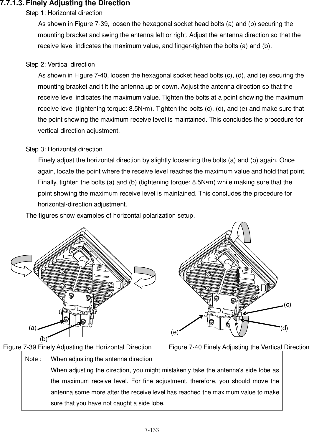
![7-134 7.7.2. The receive level and the distance In a point-to-point system, the receiving level at clear sky and the distance are related as shown in Figure 7-41. Figure 7-41 Receiving Level and Distance (QPSK) -90-80-70-60-50-40-30-20-1001 10 100 1000 10000Distance[m]Receiving Level [dBm]Transmission level (QPSK) 14 [dBm] Free space loss Lp[dB]Frequency 26 [GHz]Antenna gain[TX+RX]TX WT Antenna Gain:31dBiTYPRX WT Antenna Gain:31dBiTYP62 [dBi] λπdLp 4log20 HzfmcmλReceiving level Maximum receiving level Minimum receiving level](https://usermanual.wiki/Japan-Radio/NTG337-XL2.Manual-Part-2/User-Guide-1044923-Page-62.png)
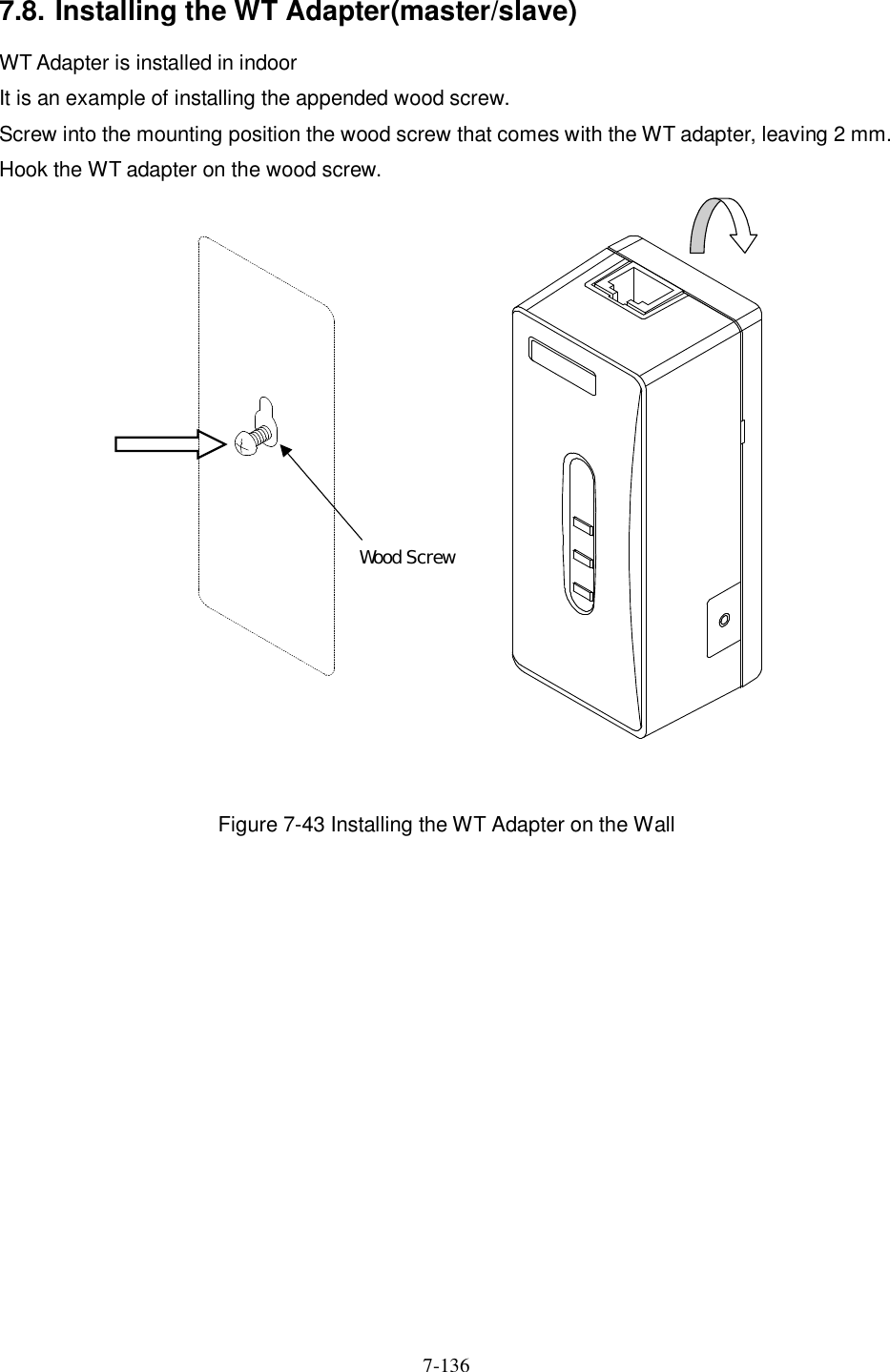
![7-135 Figure 7-42 Receiving Level and Distance (16QAM) -80-70-60-50-40-30-20-1001 10 100 1000 10000Distance[m]Receiving Level [dBm]Transmission level (16QAM) 14 [dBm] Free space loss Lp[dB]Frequency 26 [GHz]Antenna gain[TX+RX]TX WT Antenna Gain:31dBiTYPRX WT Antenna Gain:31dBiTYP62 [dBi] λπdLp 4log20 HzfmcmλMaximum receiving level Minimum receiving level Receiving level](https://usermanual.wiki/Japan-Radio/NTG337-XL2.Manual-Part-2/User-Guide-1044923-Page-63.png)
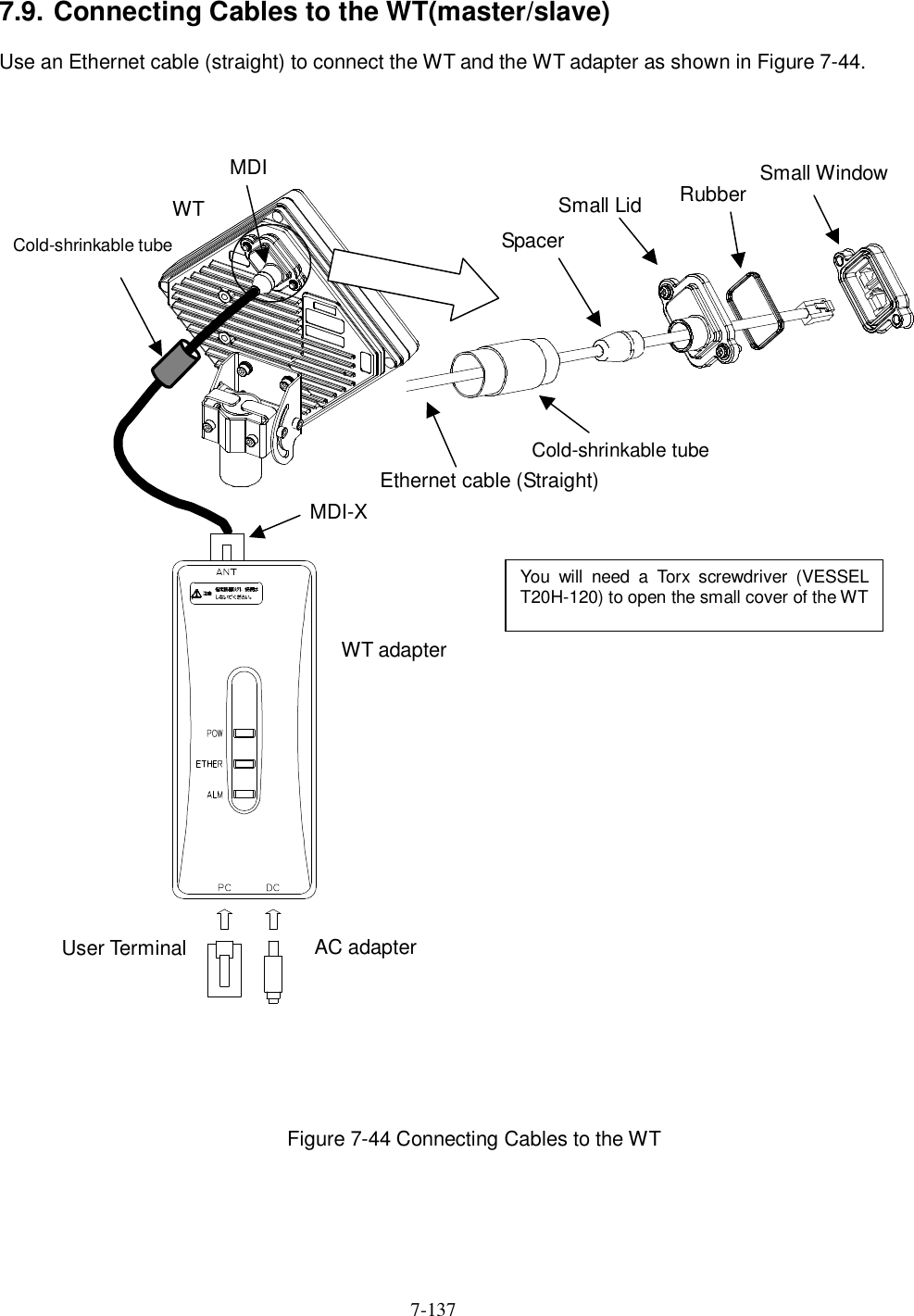
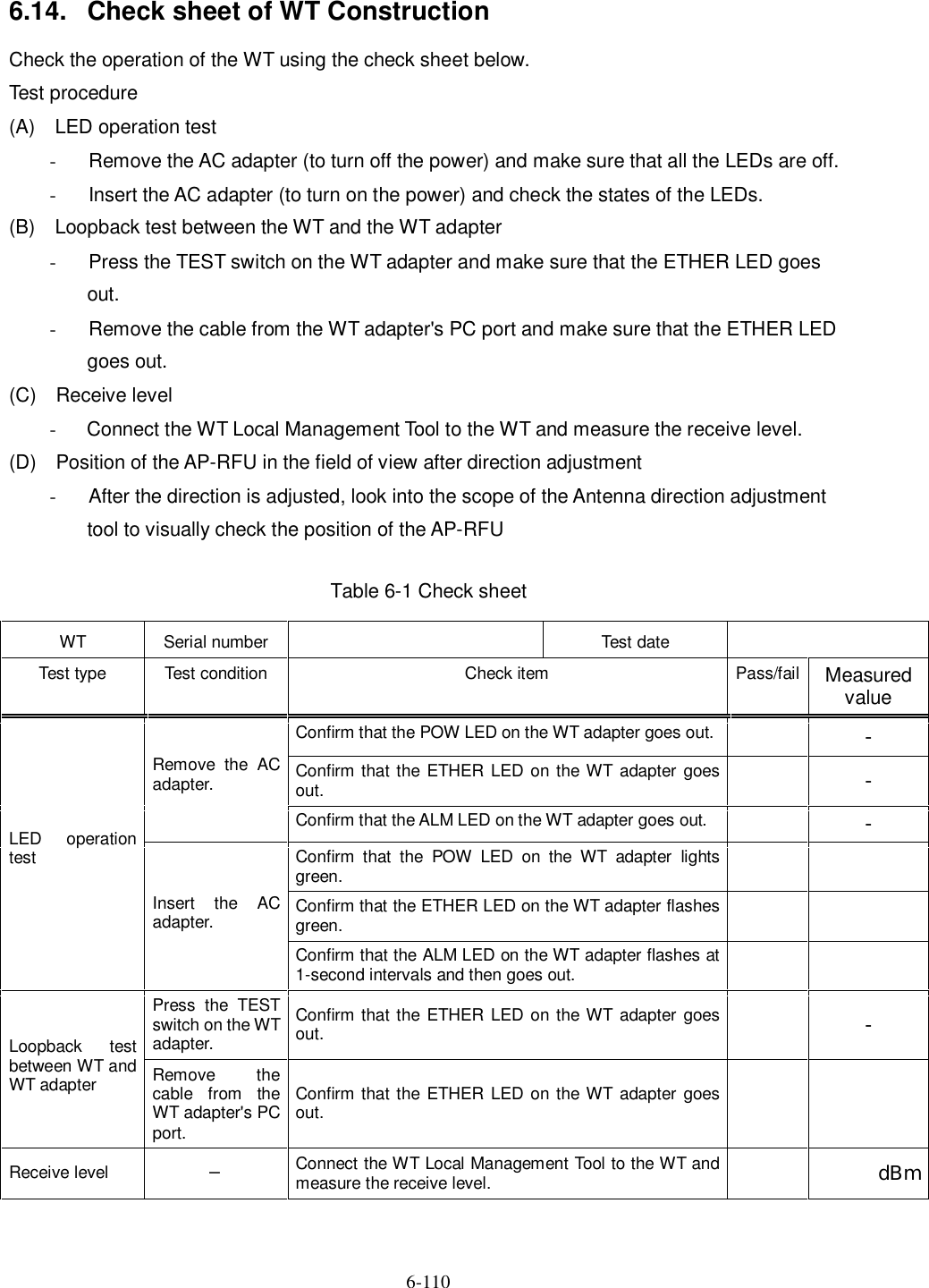
![8-150 8. Standard Tools to be Used The table below lists the tools used during installation or maintenance of the units. Table 8-1 Tools Used No. Unit name Used for: Tightening torque [N•cm] Tool 1 Door M5 265 Torx driver (VESSEL T25H-120) 2 Power board M4 127 Phillips screwdriver 3 Cable clamp M4 118 Phillips screwdriver 4 Ground M4 nut 127 Socket driver (Width across flats: 7) 5 AP-IFU SC lock(cap) G3/8 nut 110 to 150 Spanner wrench (Width across flats: 22) 6 Small window M4 127 Torx driver (VESSEL T20H-120) 7 Mounting bracket M6 850 Allen wrench (Width across flats: 5) 8 WT Ethernet cable Crimping tool for RJ-45 (Release-after-crimp type) 9 AP-RFU (Omni) Mounting bracket axis tightening M6 M16 850 9410 Socket wrench (Width across flats: 24) 10 AP-RFU (Sectoral-Horn) Mounting bracket M6 850 Allen wrench (Width across flats: 5) The appropriate tightening torque is 10% of the value indicated in the table.](https://usermanual.wiki/Japan-Radio/NTG337-XL2.Manual-Part-2/User-Guide-1044923-Page-78.png)