Japan Radio NTG337-XL2 User Station User Manual Manual Part 2
Japan Radio Co Ltd. User Station Manual Part 2
Contents
- 1. Manual
- 2. Manual Part 2
Manual Part 2
6-73
6. CONSTRUCTING A POINT-TO-MULTIPOINT SYSTEM
(WT)
6.1. Overview
OpS
Connecting the WT Local Management Tool
WT Local management tool
Installing the WT
Installing the WT Adapter
Connecting Cables to the WT
Waterproofing WT small window
Testing
Check sheet of WT Construction
Finish

6-74
6.2. OpS
6.2.1. Register the WT ID number to AP
Connect the OpS to the target AP and register a WT.
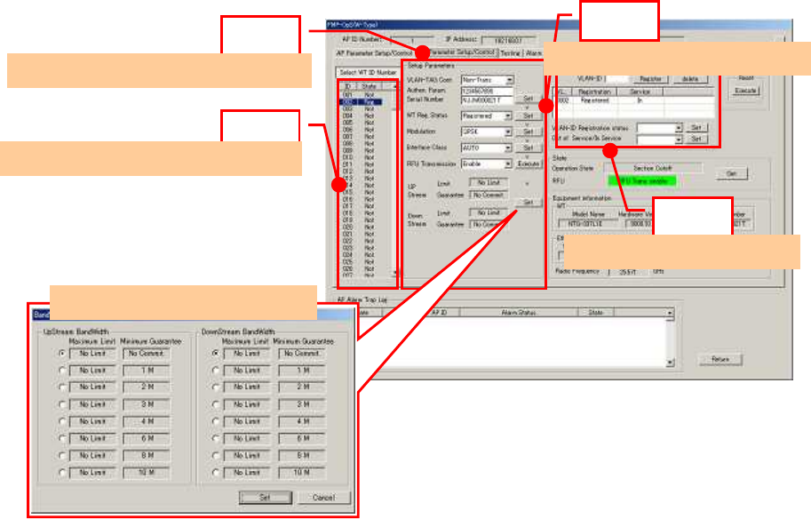
Step 1: In the OpS, select the WT Parameter Setup/Control tab.
Step 2: Select the WT from "Select WT ID number."
Step 3: Specify the setup parameters.
- VLAN-TAG Cont: Set the VLAN-TAG Cont to Transparent.
- Authen Param: Set the authentication parameter.
- Serial number: Set the serial number and click the Set button.
- WT Reg. Status: Set the WT registration status to Registered and click the Set button.
- Modulation: Set the modulation to QPSK, 16QAM, or Adaptive and click the Set button.
- Interface Class: Set the interface class to AUTO or 10BASE and click the Set button.
- RFU Transmission: Set the RFU Transmission to Enable and click the Execute button.
The following dialog box appears since a value is already set for "RFU
Transmission." Click the OK button.
- UP Stream Bandwidth table [Maximum Limit / Minimum Guarantee]
- Down Stream Bandwidth table [Maximum Limit / Minimum Guarantee]
Clicking the Set button displays a dialog box. Place checkmarks in the checkboxes and click the Set
button.
Step 4: Set the VLAN-ID.
- VLAN-ID: Set the VLAN-ID and click the Register button.
- Since the VLAN-ID that has been set appears on the screen, select it.
- VLAN-ID Registration status: Set the VLAN-ID registration status to Registered.
- Service status [ out of service / In service ] : Set the Service status to In service
6-75
Figure 6-1 Register the WT ID number to AP
Step1
Step2
Step3
Step4
Set Bandwidth
table
Select [Parameter setup/control] tab
Select the WT ID number
set parameters
Set VLAN
-
ID
6-76
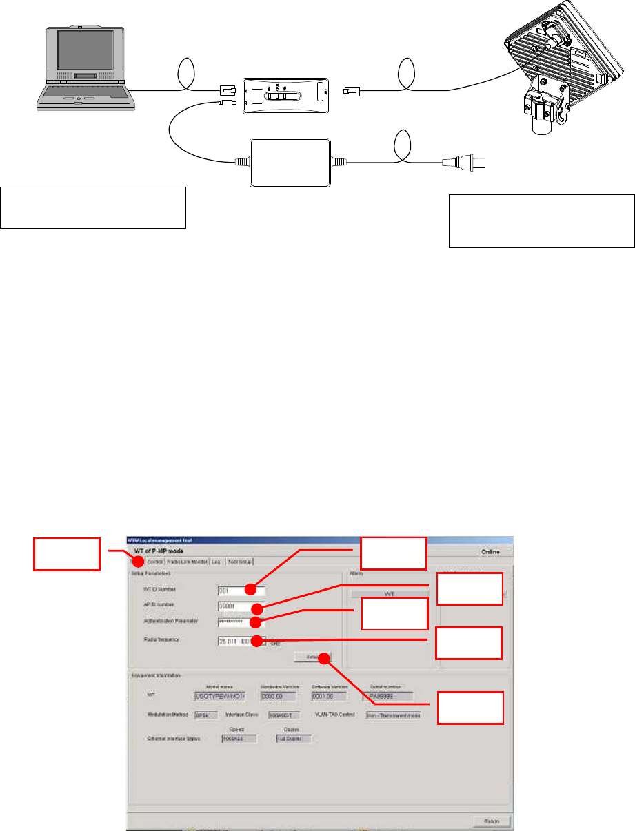
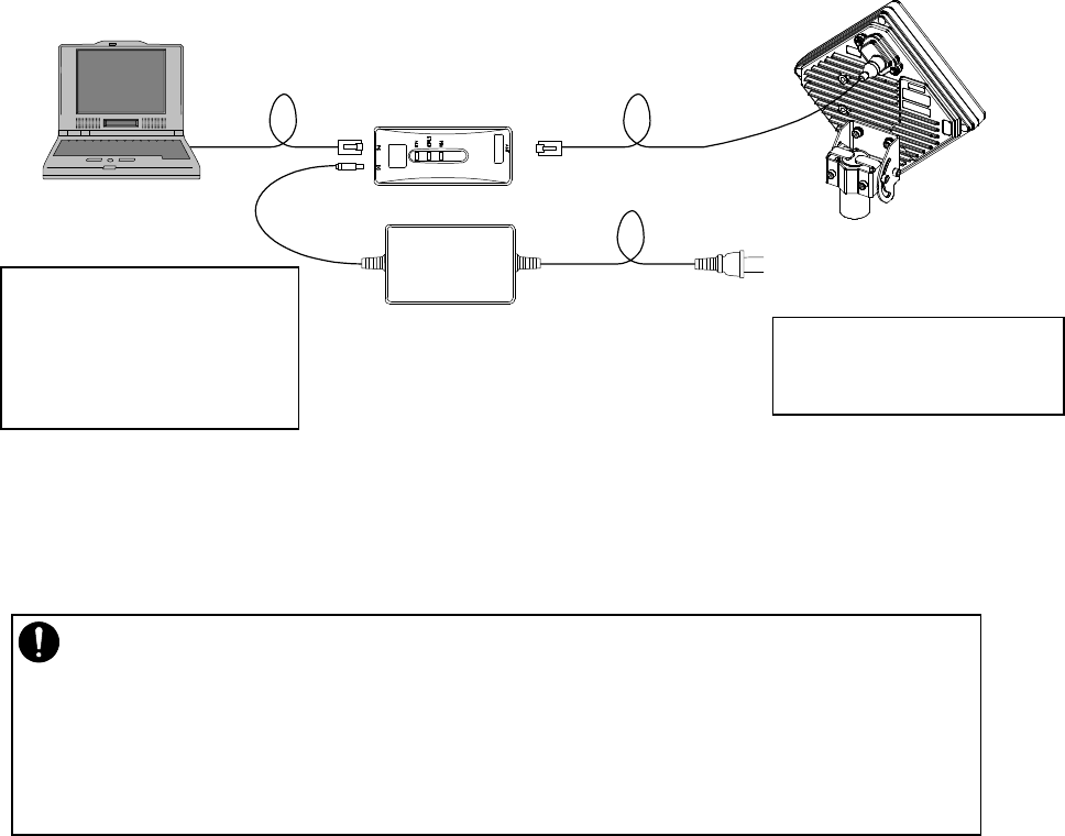
6.3. Connecting the WT Local Management Tool
Connect the WT local management tool terminal to the PC port of the WT adapter (Figure 6-2)
using a straight Ethernet cable.
Figure 6-2 Connection
6.4. WT Local management tool
6.4.1. Configure the WT
Use the WT Local Management Tool to specify the Setup Parameters.
Step 1: Select the Setup tab.
Step 2: Set the WT ID number.
Step 3: Set the AP ID number.
Step 4: Set the authentication parameter.
Step 5: Set the radio frequency.
Step 6: Click the Setup button.
Figure 6-3 Configure the WT
IP address: 192.168.1.200
Subnet mask: 255.255.255.0
WT adapter
AC Adapter AC100∼240V
DC24V
local management tool(PC)
Ethernet cable (Straight)
initial values
IP address:192.168.1.100
Subnet mask:255.255.255.0
Step 1
Step 2
Step 3
Step 4
Step 5
Step 6
6-77
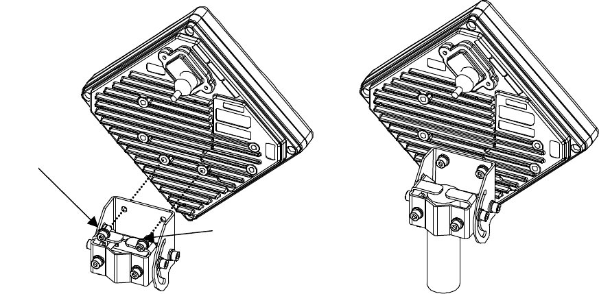
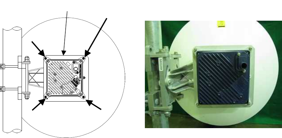
6.5. Installing the WT
6.5.1. Installing the WT
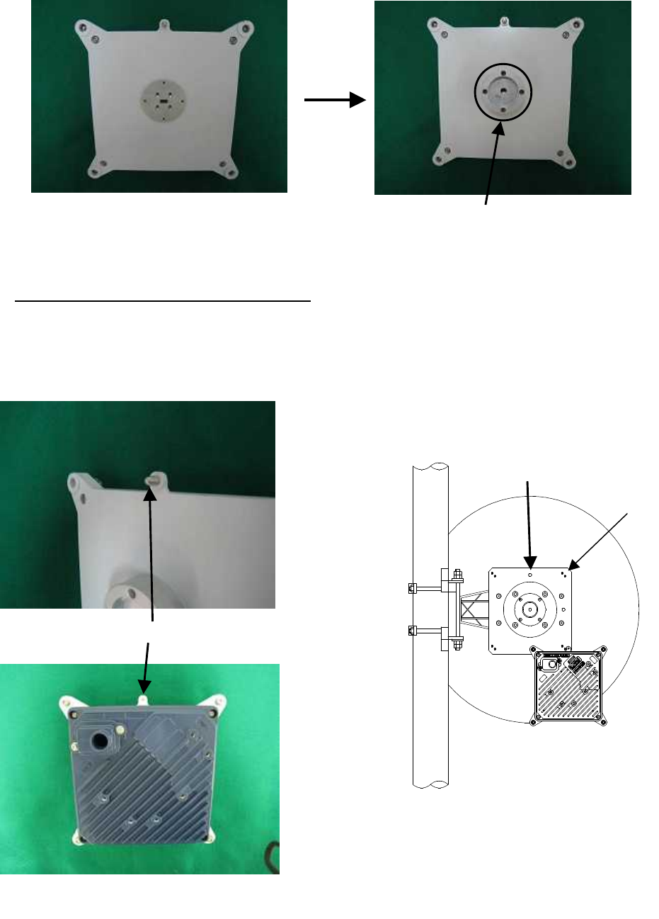
Step1 Attach the WT mounting bracket to the WT using the bolts(a)and (b).
You can orient the WT either for vertical or horizontal polarization.
Step2 Secure the WT mounting bracket to the pole using the bolts.
Applicable pole diameter: From Φ31.8mm to Φ34mm
Figure 6-4 Installing the WT
(a)
(b
)

6-78
A builder prepares a steel pipe by the installation place (a wall, a pole or etc.), and it install.
The required space of installation is shown below.
Figure 6-5 The required space of installation

6-79
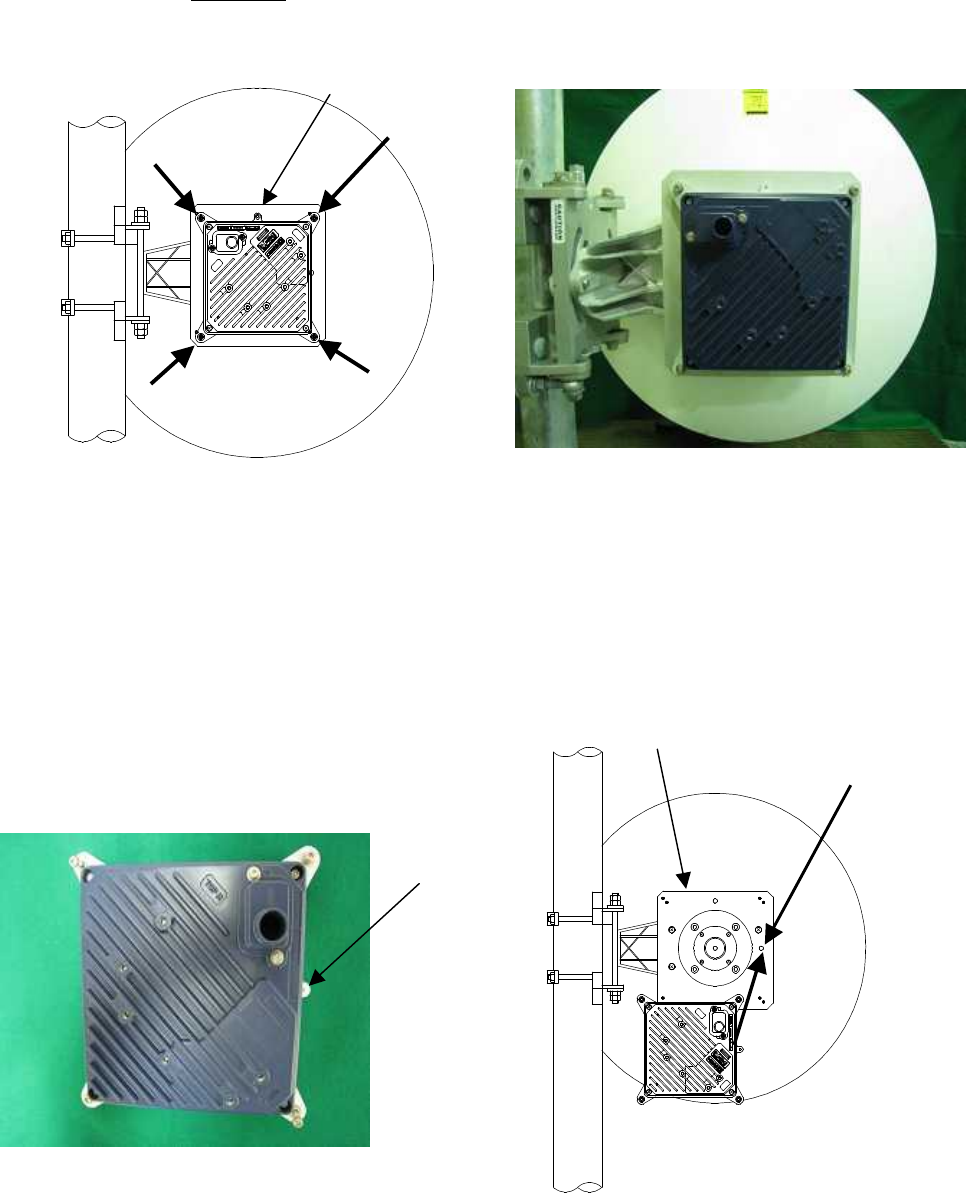
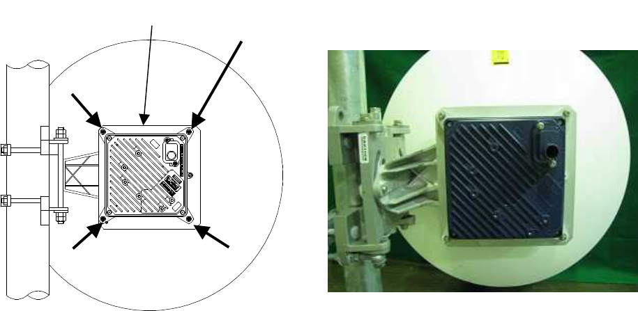
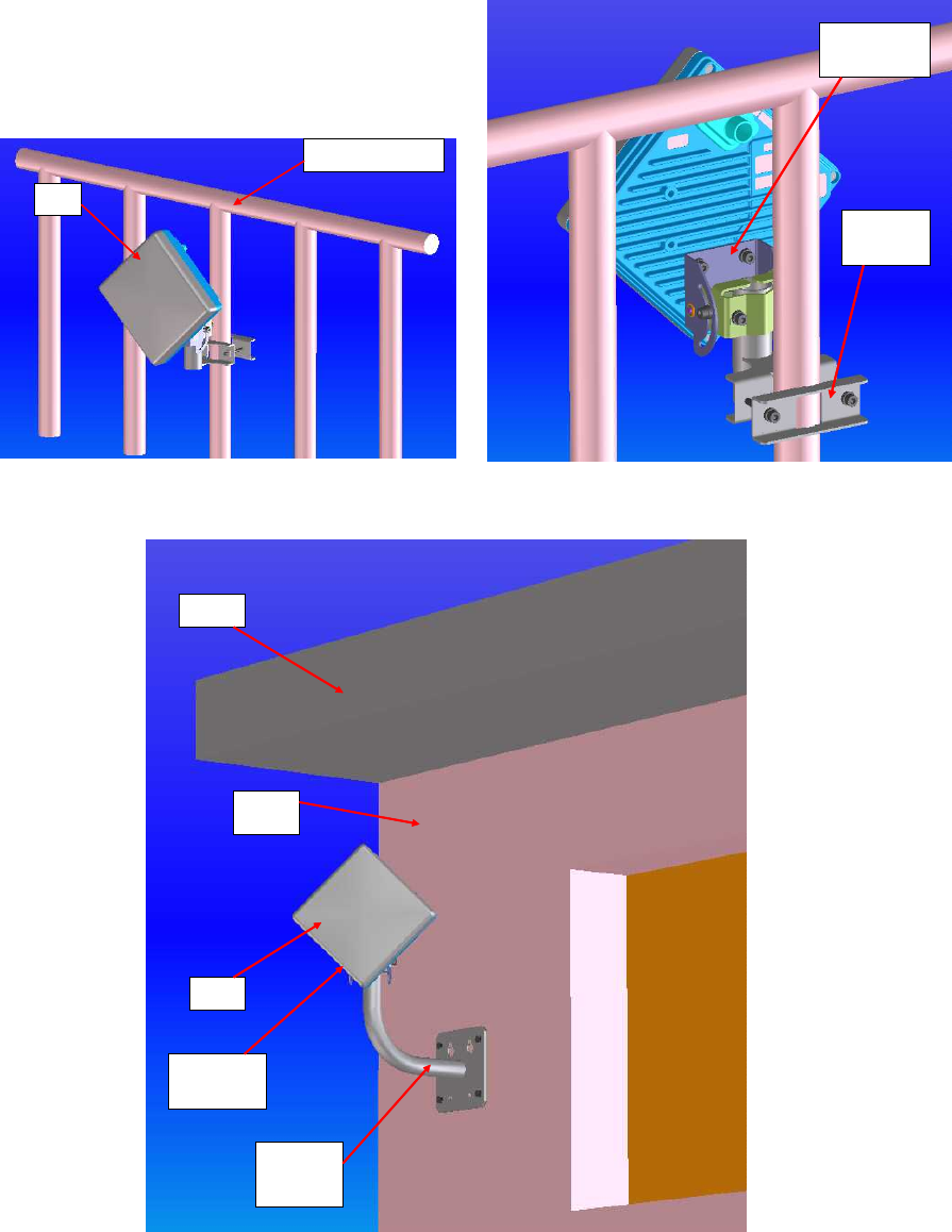
6.5.2. Example of Installing the WT
(1) On a metal fence
Figure 6-6 Installing on a metal fence
(2) On a house wall
Figure 6-7 Installing on a house wall
MOUNTING
BRACKET
FIXING
BRACKET
METAL FENCE
WT
EAVES
WT
MOUNTING
BRACKET
FIXING
BRACKET
WALL
6-80
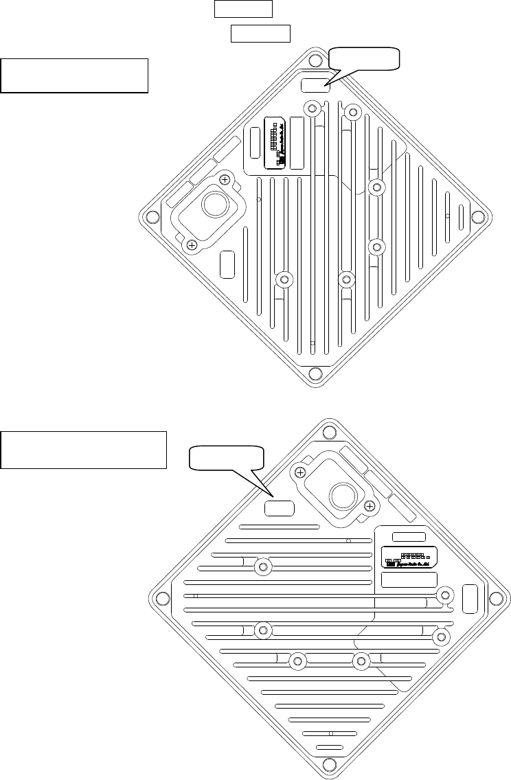
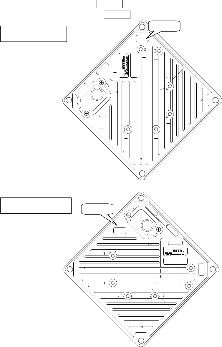
6.5.3. Setting the WT for Vertical or Horizontal Polarization
Rotate the antenna ninety degrees to choose between vertical or horizontal polarization
For vertical polarization, position TOP V at the top.
For horizontal polarization, position TOP H at the top.
Figure 6-8 Vertical Polarization
Figure 6-9 Horizontal Polarization
Vertical polarization
TOP V
TOP H
ETHE R
INPUT :
SER.NO :
MAC :
.: : : : :
MADE IN JAPAN
TYPEW−WT<EL0>
DC24V 0.7A
TOP V
Horizontal polarization
TOP V
TOP H
ETH E R
INPUT :
SER.NO :
MAC :
.: : : : :
MADE IN JAPAN
DC24V 0.7A
TYPEW−WT<EL0>
TOP H
6-81
6.6. Installing the WT (External Antenna)
6.6.1. Installing the WT (ExternalΦ30cm Antenna)
1. Φ30cm antenna installation procedure
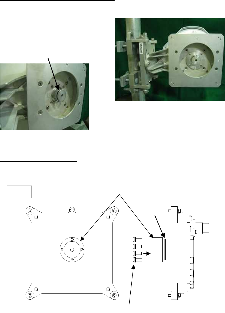
1) According to the antenna manual of RADIO WAVES, INC., set it up on the pole. (Figure 6-10)
2) Spread specified grease on the O-ring.
The spreading method depends on the
manual. (Figure 6-11)
Figure 6-10 Φ30cm antenna
Figure 6-11
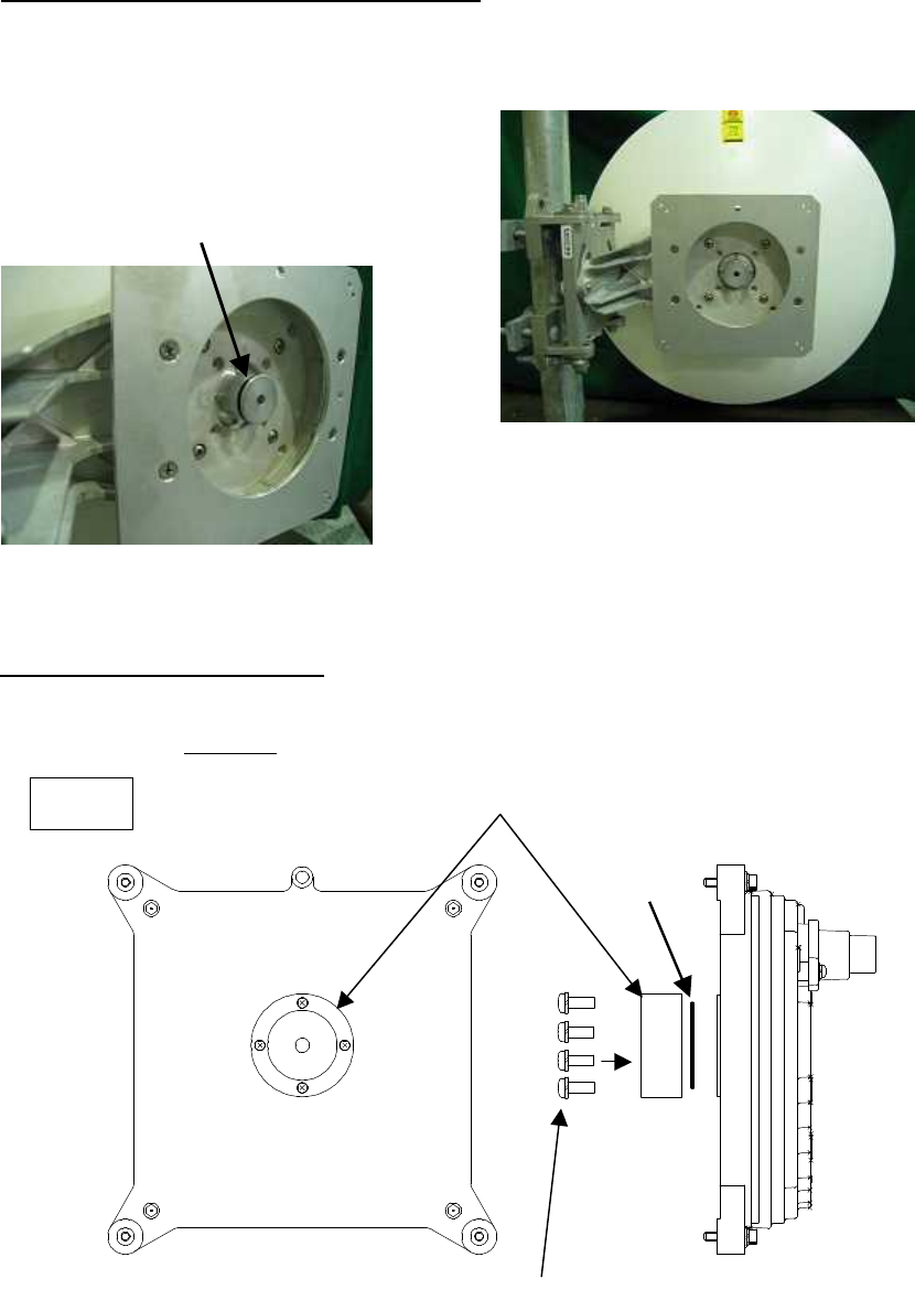
2. WT installation procedure
Attach the antenna adaptor to the WT with the O-ring using four M3 screws. (Figure 6-12 & Figure 6-13)
Tightening torque:57 N・cm
Figure 6-12
M3 screws
O-ring
Adaptor
WT
O-ring
6-82
Figure 6-13
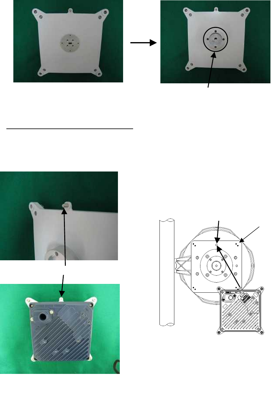
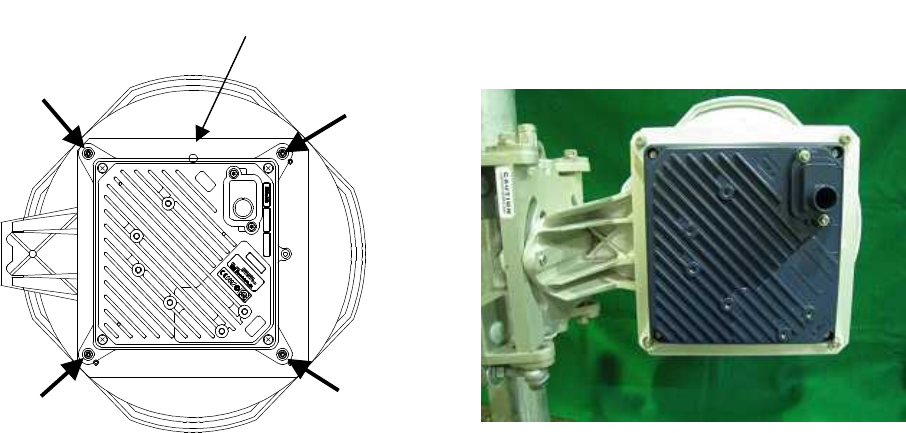
3. Attachment of the WT to the antenna
1) V(ertical) polarization
When using the V polarization, the guide pin of the WT should be turned to right above and inserted into
the V guide hole of the plate. (Figure 6-14 & Figure 6-15)
Figure 6-14
Figure 6-15
V polarization
Guide pin
I C: 76 8 B−N T G3 37 注 5
TOPV
T OP H
ET H ER
IN P UT:
S E R . NO:
M A C :
.: : : : :
MA D EI N JAP A N
DC24V0.7A
TYPEW−WT <注 1>
F C CID:C KENTG337 − 注 1
WT EL2
MO D E L: N T G −3 3 7 注2 R
V guide hole
Plate
After installing the adaptor
6-83
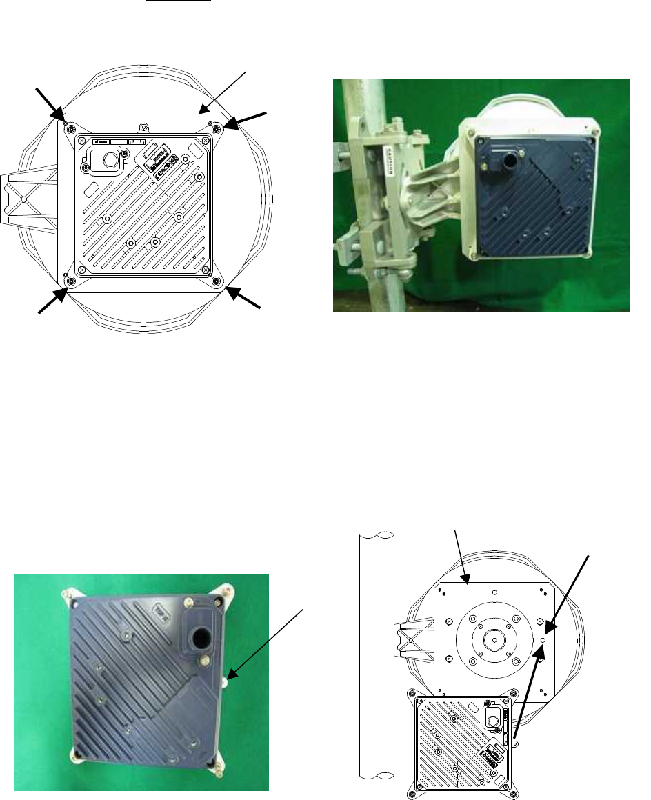
After inserting the guide pin of the WT into the guide hole, presses the WT to the plate.
While you are pressing the WT, you must be tightening the four M5 screws. (Figure 6-16)
Tightening torque:265 N・cm
Figure 6-16
2) H(orizontal) polarization
When using H polarization, the guide pin of the WT should be rotated to the right and inserted into the H
guide hole of the plate. (Figure 6-17& Figure 6-18)
Figure 6-17 Figure 6-18
I C: 7 68B −N TG 33 7 注5
TOPV
TOPH
E T H E R
INPUT:
SER.NO:
MAC :
.: : : : :
MADEINJAPAN
DC24V0.7A
TYPEW−WT<注1>
FCCID:CKENTG337−注1
WT E L2
M OD E L : N TG − 33 7注 2 R
Plate
M5 screws
Guide pin
I C: 7 68 B− N TG 33 7 注5
TOPV
TOPH
E T H ER
INPUT:
SER.NO :
MAC:
.:::: :
MADEI N J A P A N
DC24V0.7A
TY P EW−WT < 注1>
F C CI D :CKE N TG 3 3 7 − 注 1
W T EL 2
M O DE L : N T G− 3 3 7 注 2 R
Plate
H guide hole

6-84
After inserting the guide pin of the WT into the guide hole, presses the WT to the plate.
While you are pressing the WT, you must be tightening the four M5 screws. (Figure 6-19)
Tightening torque:265 N・cm
Figure 6-19
I C:7 6 8B −NTG 337 注5
TOPV
TOPH
E T H E R
INPUT:
SER.NO:
MAC:
.:::::
MADEINJAPAN
DC24V0.7A
TY PEW−WT<注1>
FCCID:CKENTG337−注 1
WT EL 2
MO DE L : N TG− 33 7 注2 R
Plate
M5 screws

6-85
6.6.2. Installing the WT (ExternalΦ60cm Antenna)
1. Φ60cm antenna installation procedure
1) According to the antenna manual of RADIO WAVES, INC., set it up on the pole. (Figure 6-20)
2) Spread specified grease on the O-ring.
The spreading method depends on the
manual. (Figure 6-21)
Figure 6-20 Φ30cm antenna
Figure 6-21
2. WT installation procedure
Attach the antenna adaptor to the WT with the O-ring using four M3 screws. (Figure 6-22 & Figure 6-23)
Tightening torque:57 N・cm
Figure 6-22
M3 screws
O-ring
Adaptor
WT
O-ring
6-86
Figure 6-23
3. Attachment of the WT to the antenna
1) V(ertical) polarization
When using the V polarization, the guide pin of the WT should be turned to right above and inserted into
the V guide hole of the plate. (Figure 6-24 & Figure 6-25)
Figure 6-24
Figure 6-25
V polarization
Guide pin
After installing the adaptor
V guide hole
Plate
TOPV
TOP H
ETHER
6-87
After inserting the guide pin of the WT into the guide hole, presses the WT to the plate.
While you are pressing the WT, you must be tightening the four M5 screws. (Figure 6-26)
Tightening torque:265 N・cm
Figure 6-26
2) H(orizontal) polarization
When using H polarization, the guide pin of the WT should be rotated to the right and inserted into the H
guide hole of the plate. (Figure 6-27 & Figure 6-28)
Figure 6-27 Figure 6-28
Guide pin
Plate
M5 screws
TOPV
TOPH
ETHER
WT E L 2
Plate
H guide hole
TOPV
TOPH
E T H E R
W T E L 2
6-88
After inserting the guide pin of the WT into the guide hole, presses the WT to the plate.
While you are pressing the WT, you must be tightening the four M5 screws. (Figure 6-29)
Tightening torque:265 N・cm
Figure 6-29
Plate
M5 screws
TOPV
TOPH
E T H E R
WT E L 2
6-89
6.7. Adjusting the Direction of the WT
To adjust the direction of the WT antenna, use the Antenna direction adjustment tool together with
the WT Local Management Tool.
Step1 Connecting the WT Local Management Tool and display the Receiving Level.
- See Subsection 6.7.1
Step2 Rough adjustment
- Install the Antenna direction adjustment tool.
- See Subsection 6.7.2
Step3 Fine adjustment
- See Subsection 6.7.3
Step4 Verification
- After adjust the direction, use the WT Local Management Tool to final check the receive
level.
If the receive level value is within the standard range, the procedure for adjusting the
antenna direction has been completed.
If the receive level value is lower than a standard value, you need to perform Step 3 again.
- Exit the WT Local Management Tool, and remove the Ethernet cable from the WT
adapter.
- Remove the Antenna direction adjustment tool.
6-90
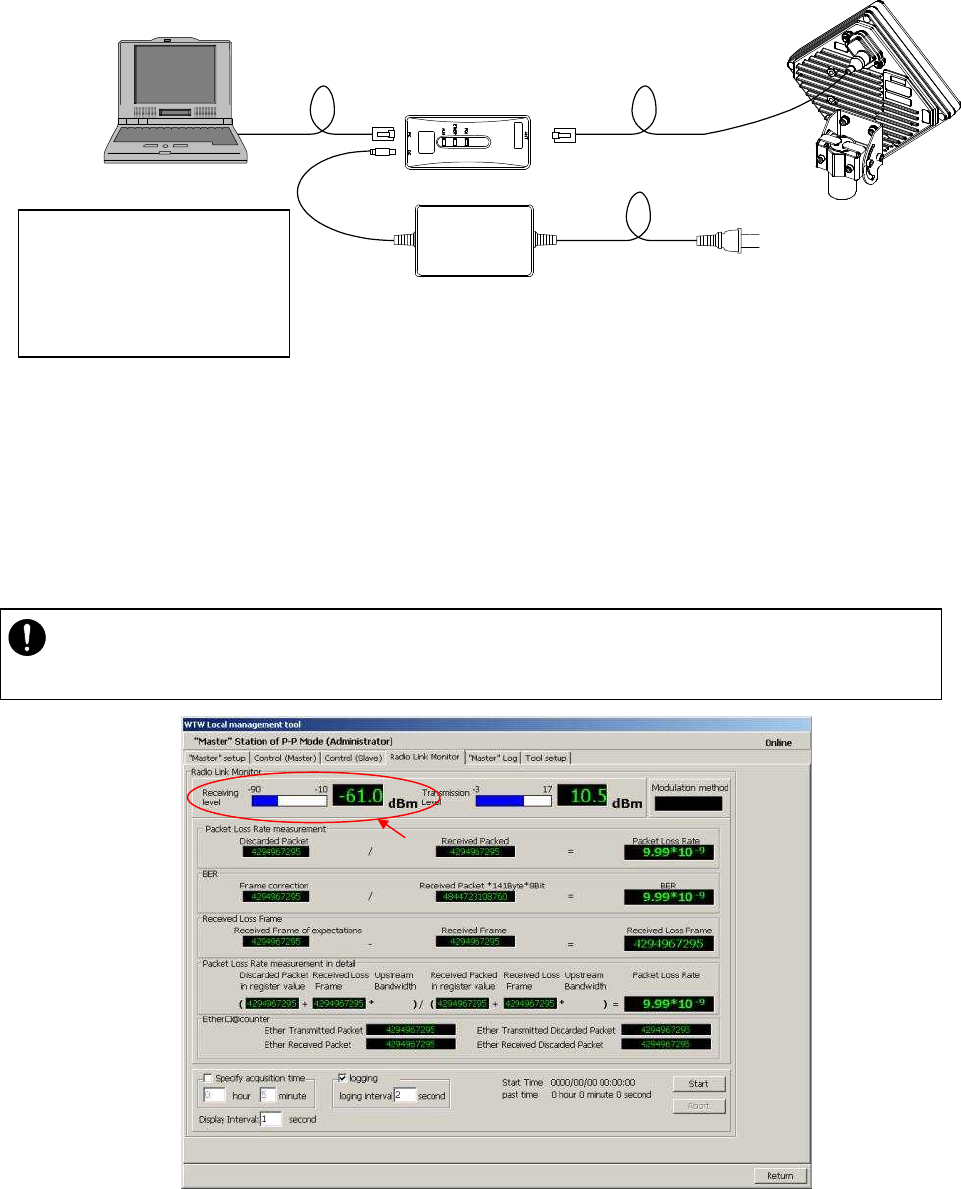
6.7.1. Connecting the WT Local Management Tool
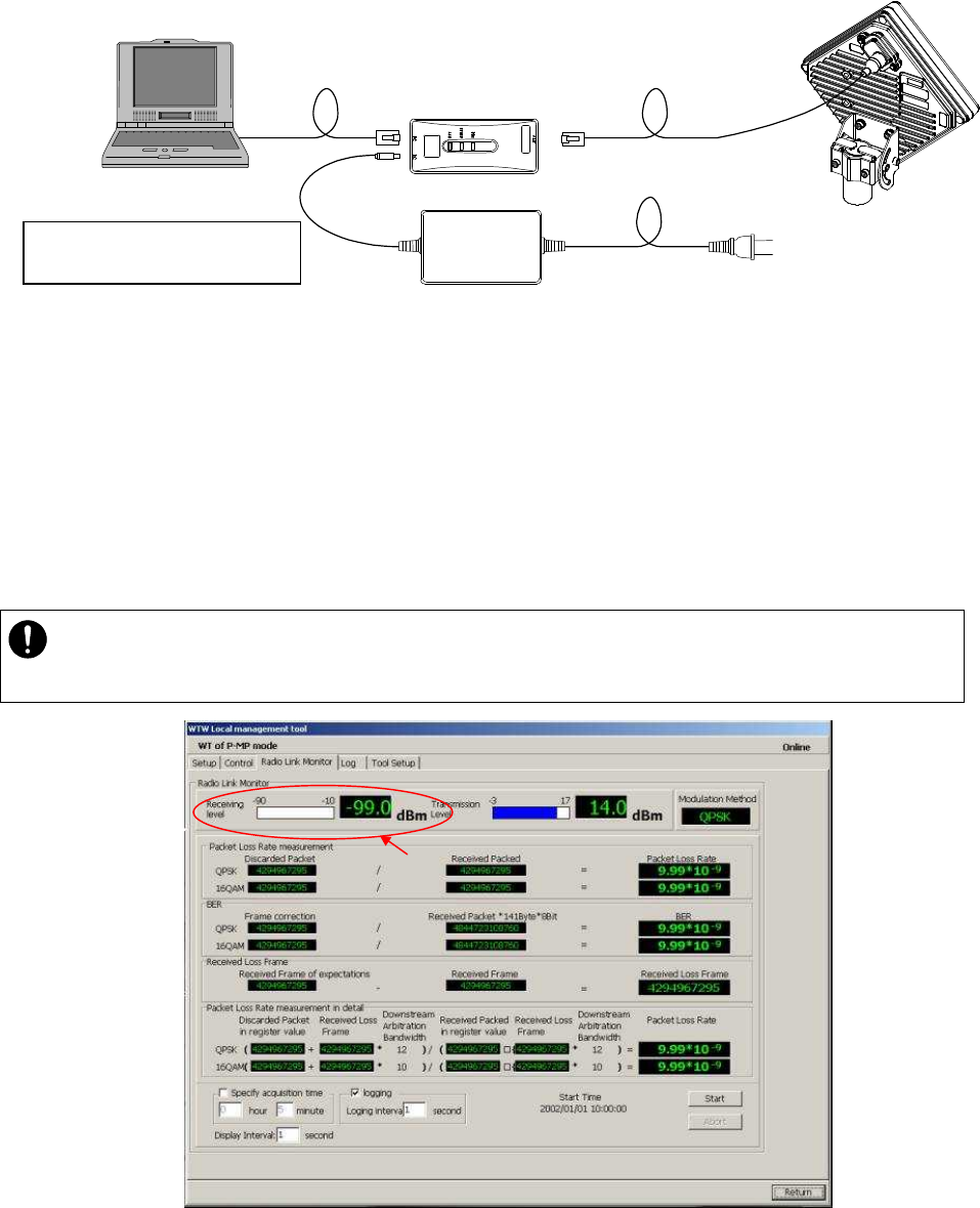
(1) As shown in Figure 6-30, connect the WT Local Management Tool (PC) to the WT adapter.
Figure 6-30 How to Install the Cabling
(2) Method of measuring the receive level of the WT (P-MP mode)
STEP1 Start the WT Local Management Tool in P-MP mode.
STEP2 Go to the Radio Link Monitor screen of the WT in P-MP mode and display the Receiving
Level.
The procedure is shown in Figure 6-31.
Figure 6-31 Method of Measuring the Receive Level
WT adapter
AC Adapter AC100∼240V
DC24V
local management tool(PC)
Ethernet cable (Straight)
IP address: 192.168.1.200
Subnet mask: 255.255.255.0
・
The Receiving Level provides a display interval of 1 second, and you need to adjust the
antenna direction slowly.
6-91
(f) (e)
(d)
(b) (C)
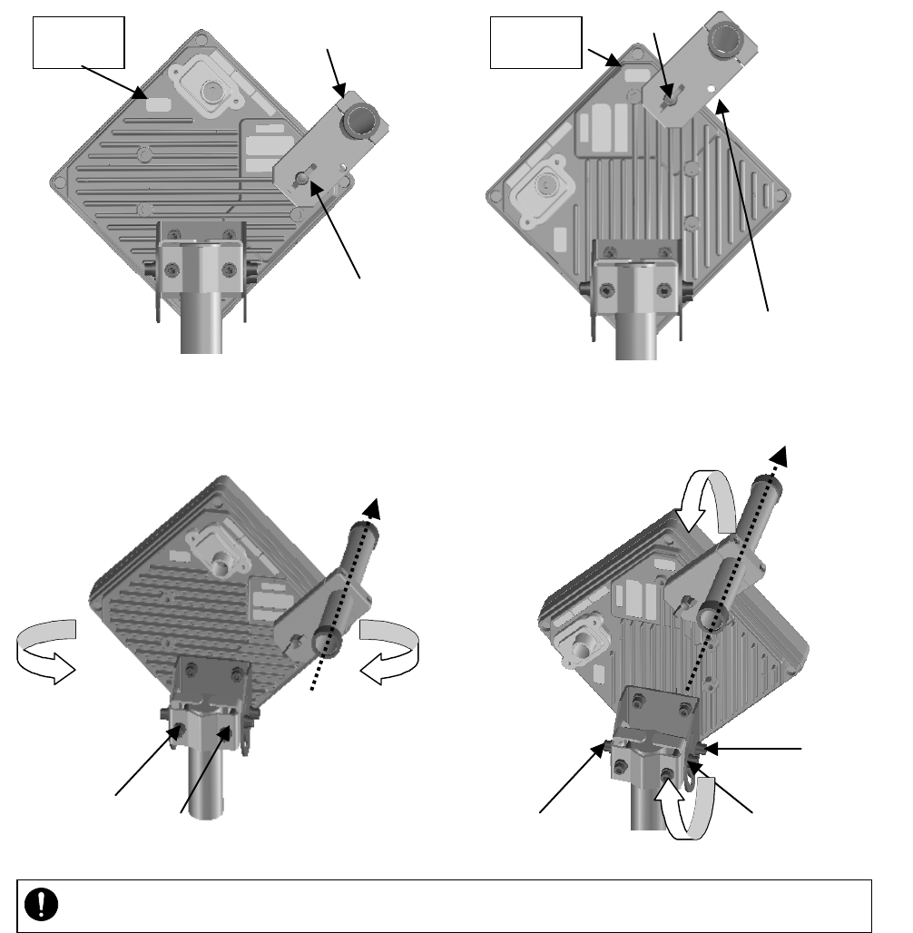
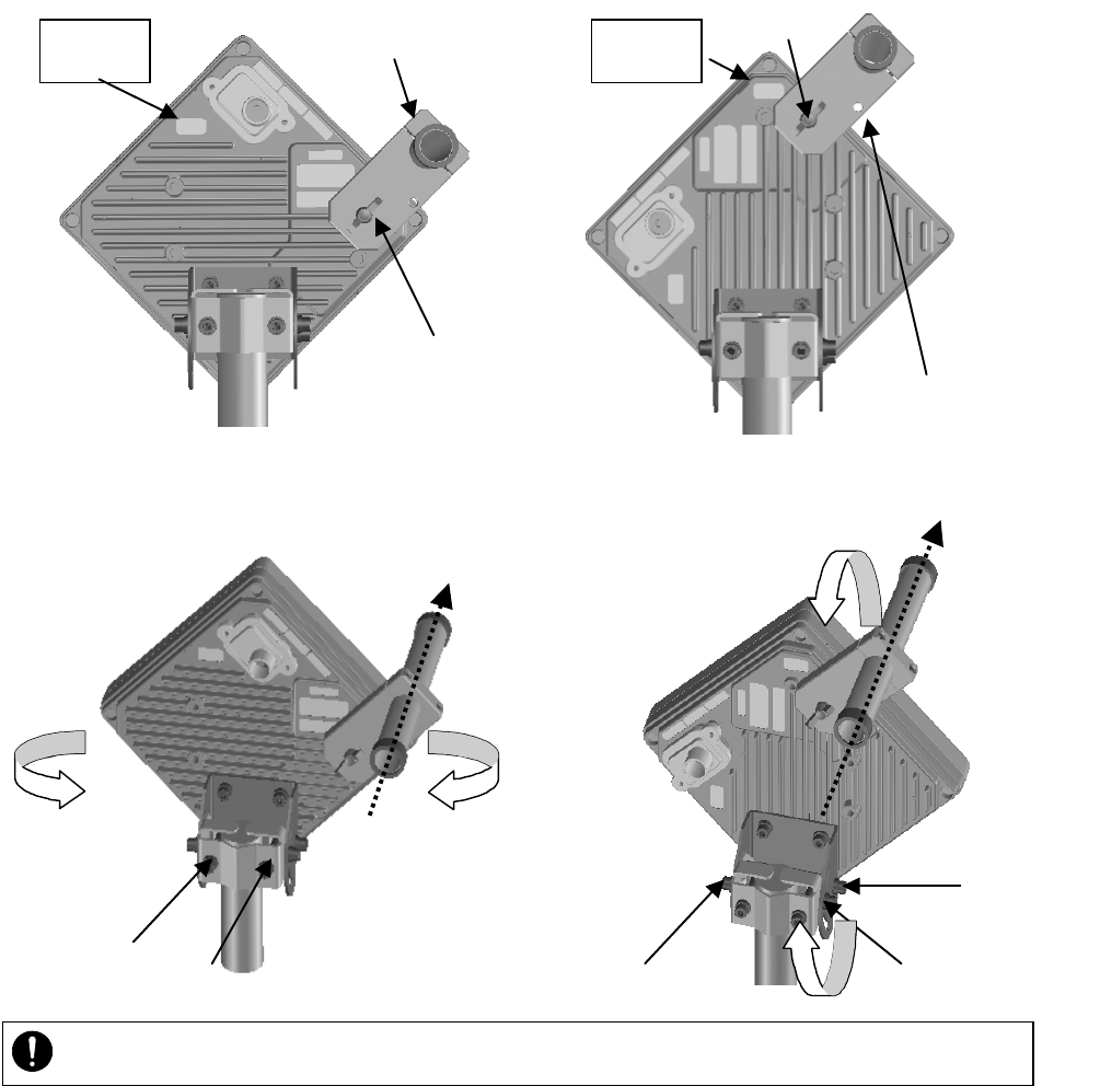
6.7.2. Roughly Adjusting the Direction
Step1 As shown in Figure 6-32 and Figure 6-33, use the wing bolt (a) to attach the Antenna
direction adjustment tool.
Step2 As shown in Figure 6-34, loosen the hexagonal socket head bolts (b) and (c) securing the
mounting bracket and swing the antenna left or right. Adjust the antenna approximately for
the WT direction and finger-tighten the bolts (b) and (c).
Step3 As shown in Figure 6-35, loosen the bolts (d), (e), and (f) and tilt the antenna up or down.
Perform vertical-direction adjustment so that the WT of the opposite station can be seen
through the scope of the Antenna direction adjustment tool.
Figure 6-32 How to Install Direction Adjustment tool
when the antenna type is the horizontal polarization
Figure 6-33 How to Install Direction Adjustment tool
when the antenna type is the vertical polarization
In Figure 6-34 and Figure 6-35 is an example when the antenna type is the horizontal polarization.
Figure 6-34 Rough-adjusting Horizontal Direction Figure 6-35 Rough-Adjusting the Vertical Direction
・ Never look at the sun directly. Doing so may seriously damage the eyes.
Direction adjustment tool
TOP V
(a)
TOP H
Direction adjustment tool
(a)
6-92
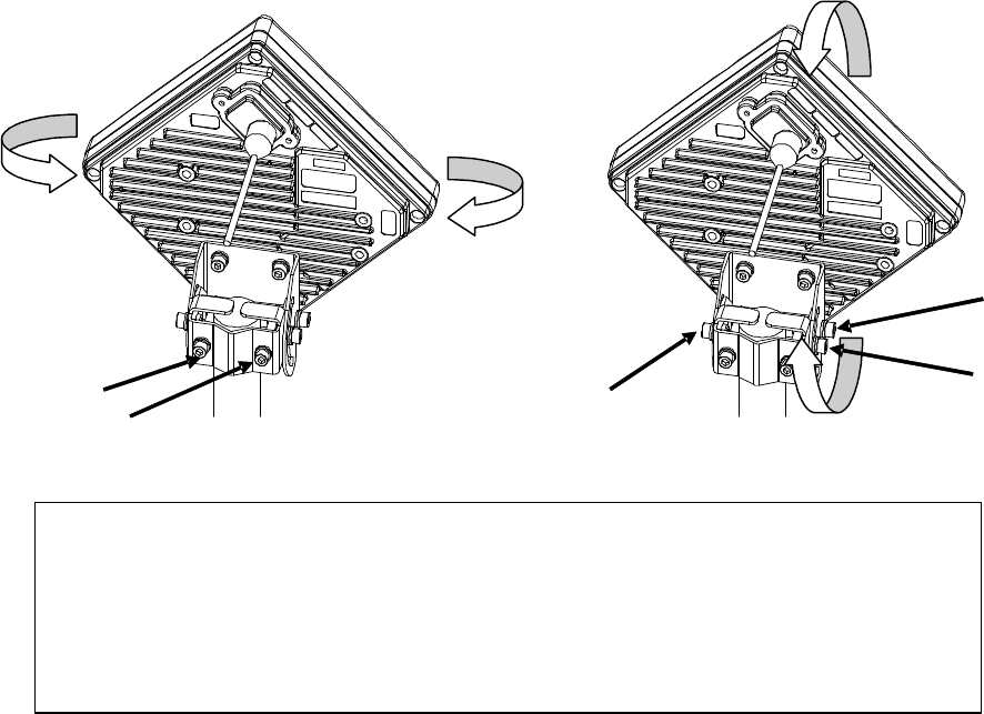
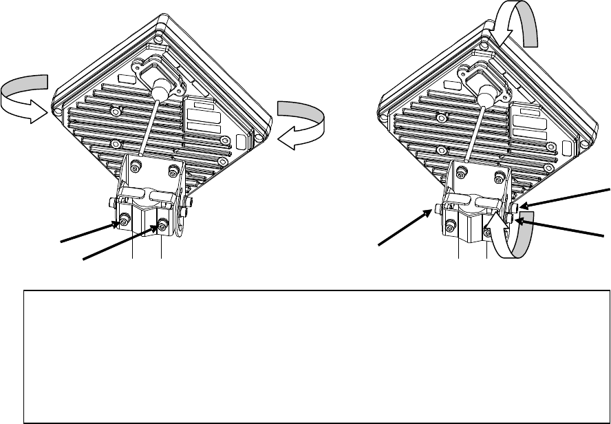
6.7.3. Finely Adjusting the Direction
Step 1: Horizontal direction
As shown in Figure 6-36, loosen the hexagonal socket head bolts (a) and (b) securing the
mounting bracket and swing the antenna left or right. Adjust the antenna direction so that the
receive level indicates the maximum value, and finger-tighten the bolts (a) and (b).
Step 2: Vertical direction
As shown in Figure 6-37, loosen the hexagonal socket head bolts (c), (d), and (e) securing the
mounting bracket and tilt the antenna up or down. Adjust the antenna direction so that the
receive level indicates the maximum value. Tighten the bolts at a point showing the maximum
receive level (tightening torque: 8.5N•m). Tighten the bolts (c), (d), and (e) and make sure that
the point showing the maximum receive level is maintained. This concludes the procedure for
vertical-direction adjustment.
Step 3: Horizontal direction
Finely adjust the horizontal direction by slightly loosening the bolts (a) and (b) again. Once
again, locate the point where the receive level reaches the maximum value and hold that point.
Finally, tighten the bolts (a) and (b) (tightening torque: 8.5N•m) while making sure that the
point showing the maximum receive level is maintained. This concludes the procedure for
horizontal-direction adjustment.
The figures show examples of horizontal polarization setup.
Figure 6-36 Finely Adjusting the Horizontal Direction
Figure 6-37 Finely Adjusting the Vertical Direction
(a)
(b)
(d)
(c)
(e)
Note : When adjusting the antenna direction
When adjusting the direction, you might mistakenly take the antenna's side lobe as
the maximum receive level. For fine adjustment, therefore, you should move the
antenna some more after the receive level has reached the ma
ximum value to make
sure that you have not caught a side lobe.
6-93
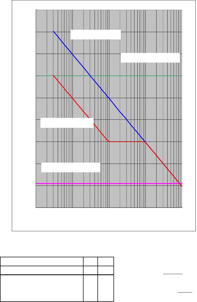
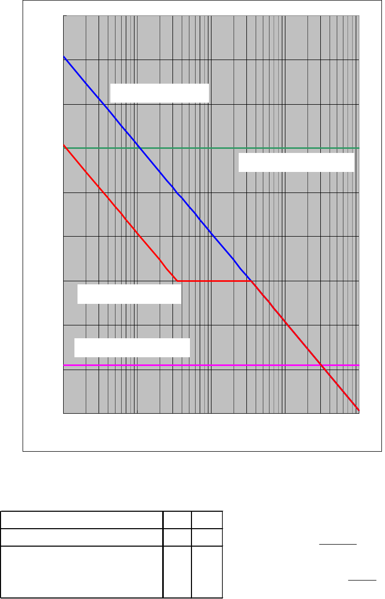
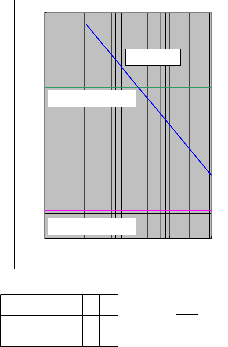
6.7.4. The receive level and the distance
For the receiving AP-RFU (Sectoral-Horn Antenna) in a point-to-multipoint system, the receiving
level at clear sky and the distance are related as shown in Figure 6-38.
Figure 6-38 Receiving Level and Distance (Sectoral QPSK)
-90
-80
-70
-60
-50
-40
-30
-20
-10
0
1 10 100 1000 10000
Distance[m]
Receiving Level [dBm]
Maximum Receiving Level
WT Receiving Level
AP Receiving Level
Minimum Receiving Level
Transmission level (QPSK) 14 [dBm] Free space loss Lp[dB]
Frequency 26 [GHz]
Antenna gain[TX+RX]
TX Sectoral Antenna Gain:15.5dBiTYP
RX WT Antenna Gain:31dBiTYP
46.5 [dBi]
λ
πd
Lp 4
log20
Hzf
mc
mλ
6-94
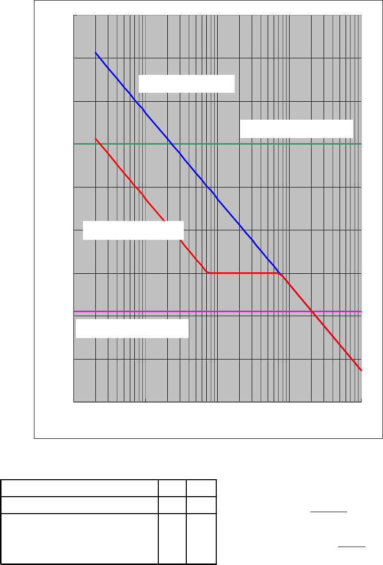
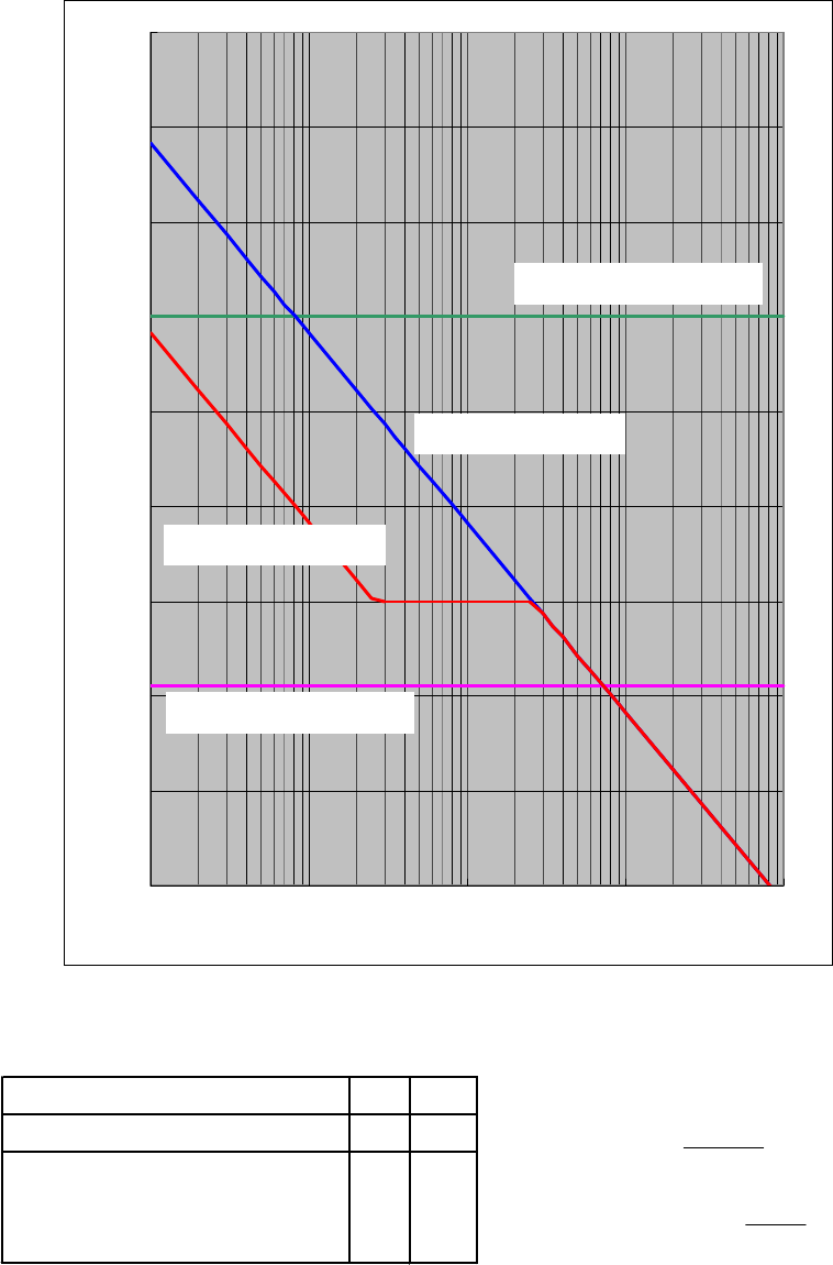
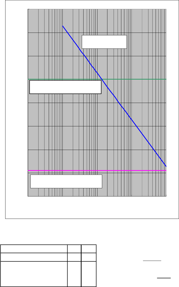
Figure 6-39 Receiving Level and Distance (Sectroral 16QAM)
-90
-80
-70
-60
-50
-40
-30
-20
-10
0
1 10 100 1000 10000
Distance[m]
Receiving Level [dBm]
Transmission level (QPSK) 11.5 [dBm] Free space loss Lp[dB]
Frequency 26 [GHz]
Antenna gain[TX+RX]
TX Sectoral Antenna Gain:15.5dBiTYP
RX WT Antenna Gain:31dBiTYP
46.5 [dBi]
λ
πd
Lp 4
log20
Hzf
mc
mλ
WT Receiving Level
Maximum Receiving Level
AP Receiving Level
Minimum Receiving Level
(16QAM)
6-95
Figure 6-40 Receiving Level and Distance (Omni QPSK)
-90
-80
-70
-60
-50
-40
-30
-20
-10
0
1 10 100 1000 10000
Distance[m]
Receiving Level [dBm]
Transmission level (QPSK) 14 [dBm] Free space loss Lp[dB]
Frequency 26 [GHz]
Antenna gain[TX+RX]
TX Sectoral Antenna Gain:6.5dBiTYP
RX WT Antenna Gain:31dBiTYP
37.5 [dBi]
λ
πd
Lp 4
log20
Hzf
mc
mλ
Maximum Receiving Level
AP Receiving Level
Minimum Receiving Level
WT Receiving Level
6-96
Figure 6-41 Receiving Level and Distance (Omni 16QAM)
-90
-80
-70
-60
-50
-40
-30
-20
-10
0
1 10 100 1000 10000
Distance[m]
Receiving Level [dBm]
Transmission level (QPSK) 11.5 [dBm] Free space loss Lp[dB]
Frequency 26 [GHz]
Antenna gain[TX+RX]
TX Sectoral Antenna Gain:6.5dBiTYP
RX WT Antenna Gain:31dBiTYP
37.5 [dBi]
λ
πd
Lp 4
log20
Hzf
mc
mλ
(16QAM)
WT Receiving Level
Maximum Receiving Level
AP Receiving Level
Minimum Receiving Level

6-97
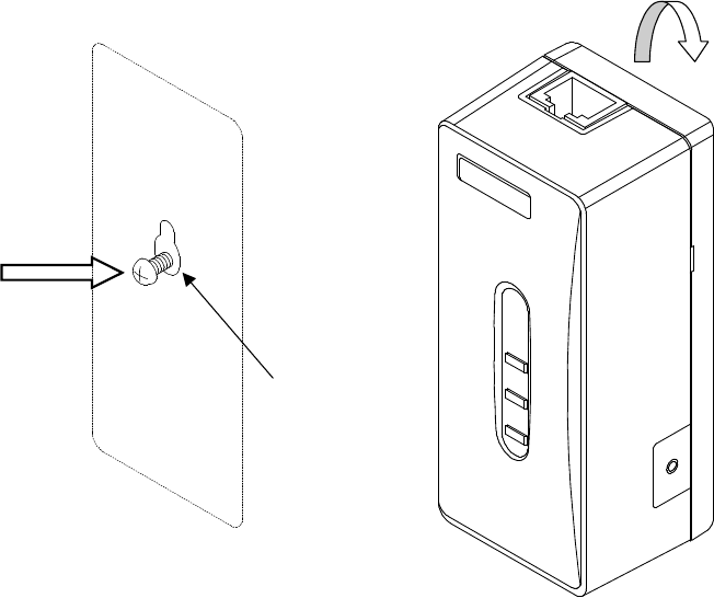
6.8. Installing the WT Adapter
WT Adapter is installed in indoor
It is an example of installing the appended wood screw.
Screw into the mounting position the wood screw that comes with the WT adapter, leaving 2 mm.
Hook the WT adapter on the wood screw.
Wood Screw
Figure 6-42 Installing the WT Adapter on the Wall
6-98
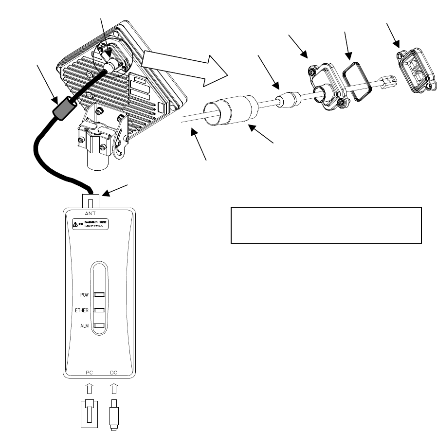
6.9. Connecting Cables to the WT
Use an Ethernet cable (straight) to connect the WT and the WT adapter as shown in Figure 6-43.
Figure 6-43 Connecting Cables to the WT
MDI
MDI-X
WT adapter
Cold-shrinkable tube
Small
Lid
Rubber
Ethernet cable (Straight)
You will need a Torx screwdriver (VESSEL
T20H-120) to open the small cover of the WT
AC adapter
User Terminal
WT
Cold-shrinkable tube
Spacer
Small
Window
6-99
(1) Connected cable between WT and ANT port of WT adapter
(2) Connect the user terminal to PC port of WT adapter
(3) Connect the AC adapter to DC port to the WT adapter
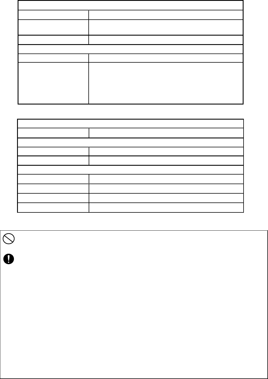
Cable
Cable type Ethernet cable for outdoor,straight
Range of applicable outer
diameter φ5.0 mm∼5.7mm
Cable length 50m (maximum)
Connector of both side
Shape RJ-45
Cable connection Straight connection
- WT : MDI
- ANT port of WT adapter : MDI-X
An Ethernet cable has eight signal lines. Four lines are
used to carry Ethernet signals. The remaining four lines are
used as power lines and LED control lines.
Interface
Interface 10BASE-T/100BASE-TX
Connector
Shape RJ-45
Pin assign Ethernet signal(MDI-X)
Cable
Communication terminal Cable connection
PC straight
HUB crossover
ROUTER straight
・
Never connect your personal computer to the ANT port of the WT adapter. Doing so may
damage your personal computer.
・ The cable connecting between
the WT and WT adapter carries 24 VDC for the WT in
addition to Ethernet signals. Before unplugging the cable connecting between the WT and
WT adapter, make sure to unplug the DC jack of the WT adapter to turn the power off.
Otherwise, the unit may be damaged.
・
When closing the small window, make sure that the rubber packing of the small window is
free from any foreign matter.
・
The cable connecting the WT and WT adapter is a straight cable. Wrong connection may
damage the unit.
・ The Equipment for connection to WT adapter PC-interface(RJ-45) shall be appropriate to
connect to TNV-1 circuits.
・
For the connection WT adapter to WT and a cable suitable for outdoor use shall be
installed.
6-100
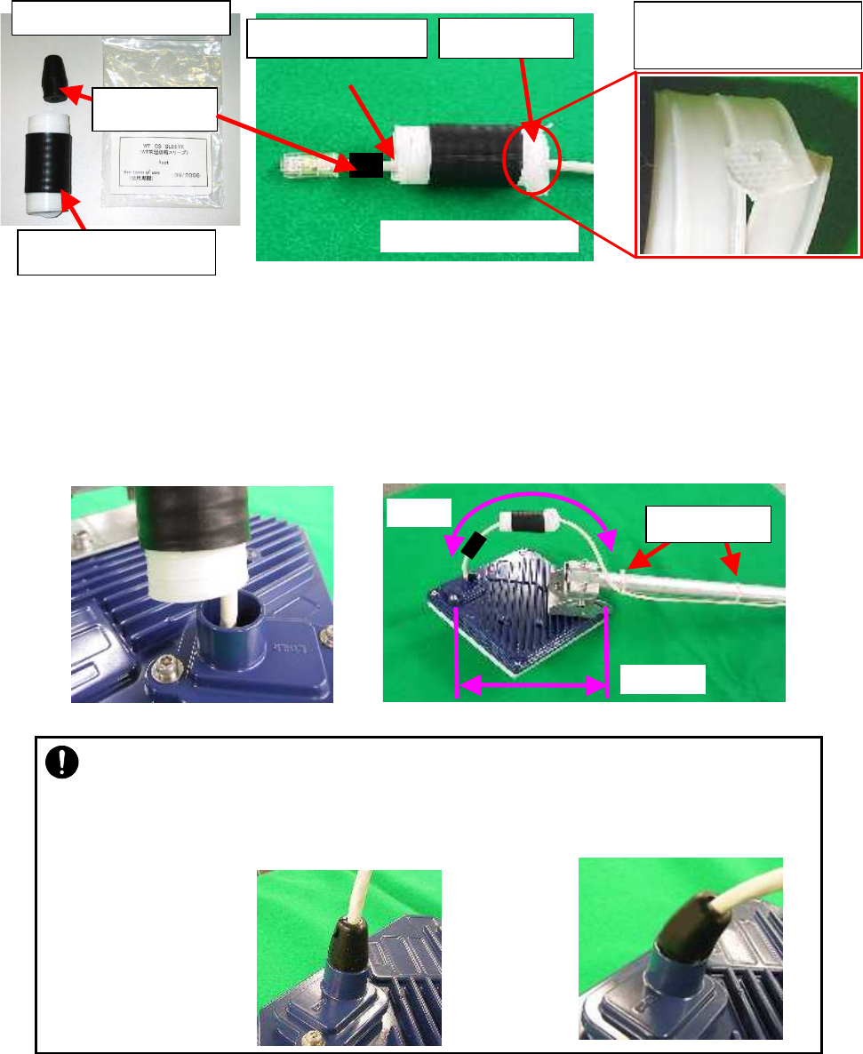
6.10. Waterproofing WT small window
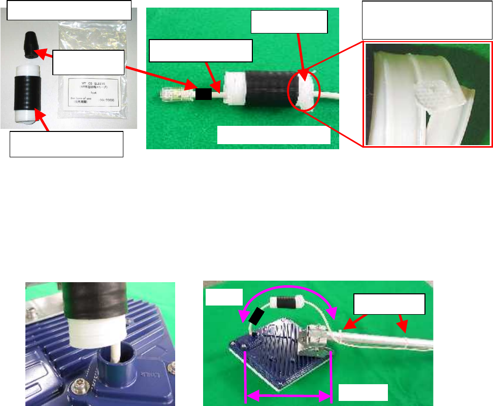
(1) Pass the Ethernet cable through the cold-shrinkable tube (a) from the bonded portion of the
spiral tube. Pay attention to the insertion direction (Figure 6-45).
Applicable LAN cable diameter: 5.0 mm to 5.7 mm
Figure 6-44 Figure 6-45
(2) Connect the Ethernet cable to the WT (Figure 6-46).
(3) Using cable ties (c) or the like, secure the Ethernet cable to the supporting bracket. Attach the
cable ties 70 to 100 mm from the end of the supporting bracket. The cable is approximately
300 mm long measured from the cable joint (with a diameter of approximately 200 mm) to the
first cable tie (Figure 6-47).
Figure 6-46 Figure 6-47
(d) Spacer
(a) Cold-shrinkable tube
Pay attention to the irection
(b) Ether
net cable
Bonding portion of the spiral
tube for the cold-shrinkable
Components of CS sleeve
(e) Spiral tube
(c Cable ties
φ200mm
300mm
6-101
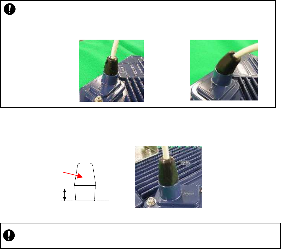
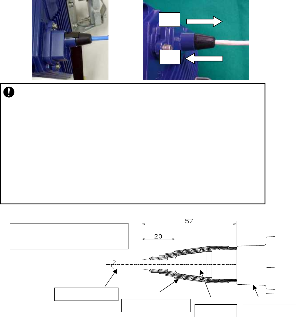
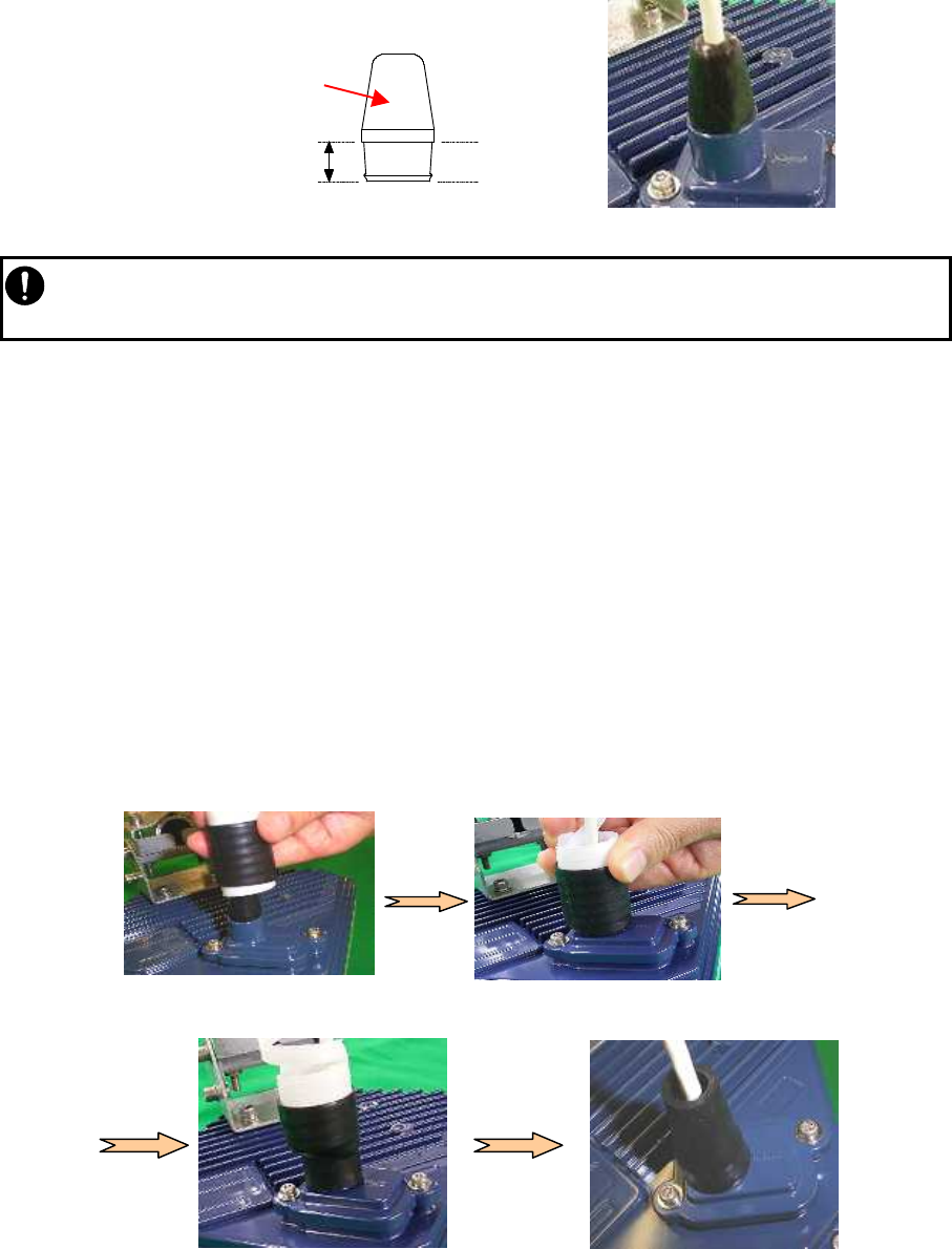
(4) Mounting spacer (d)
- Mount the spacer on the Ethernet cable .
- Make sure that the spacer is fully inserted in the small Lid of the WT(Figure 6-49).
Figure 6-49
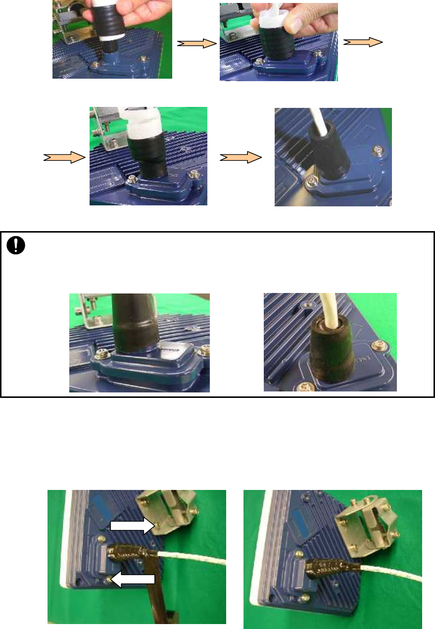
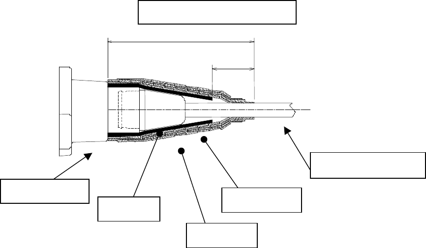
(5) Mounting cold-shrinkable tube (a)
- Place the cold-shrinkable tube on the spacer and small Lid (Figure 6-50).
- Butt the end of the cold-shrinkable tube against the base of the small Lid. Pulling white
spiral tube (e) to the very edge of the cold-shrinkable tube eases the subsequent
procedure (Figure 6-50).
- Pull the spiral tube to mount the edge of the cold-shrinkable tube on the small Lid (Figure
6-51). Make sure that there is no gap between the cold-shrinkable tube and the base of
the small Lid and between the spacer and the small Lid.
- Pull the spiral tube to mount the cold-shrinkable tube, paying attention so the spacer is
not lifted (Figure 6-52 and Figure 6-53). Make sure that the spacer is not protruded from
the cold-shrinkable tube. The top of the cold-shrinkable tube should be 5 mm or less from
the top of the spacer.
・
Never allow the inside of the small window to become wet. Dampness may cause a
malfunction. Connect the Ethernet cable perpendicular to the WT. Failure to do so
will spoil the waterproofing effect, resulting in a device malfunction.
Bent cable
Cable perpendicular
to the WT
OK
(d)
Inserted
Spacer
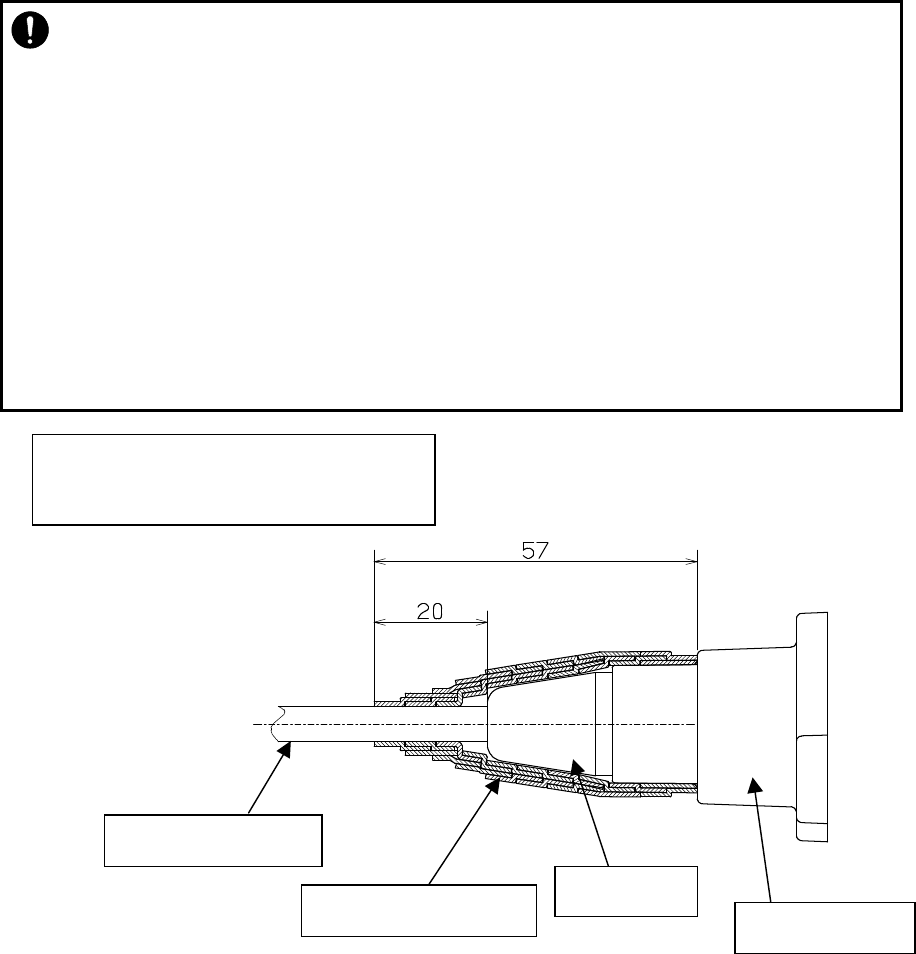
・
Insert the spacer into the small window fully. Partial insertion of the spacer will spoil the
waterproofing effect.
NG
Figure 6-48
6-102
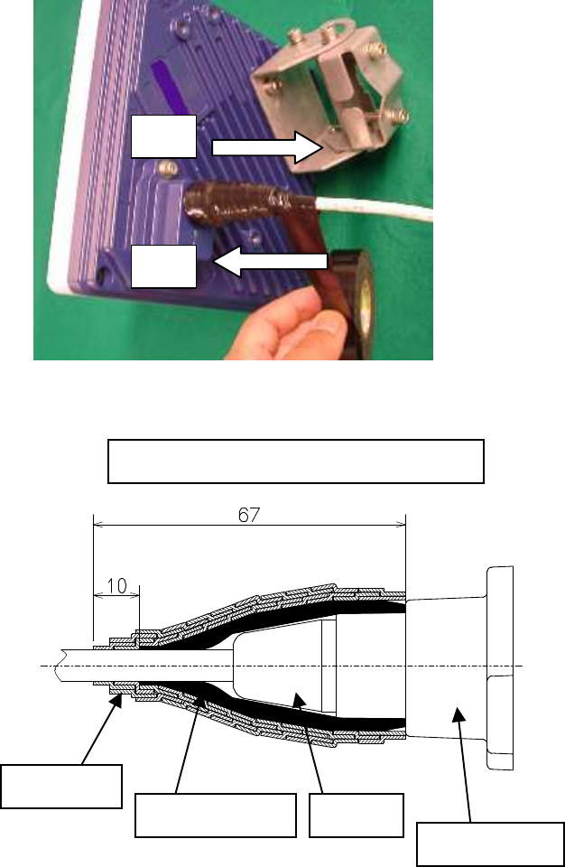
Figure 6-50 Figure 6-51
Figure 6-52 Figure 6-53
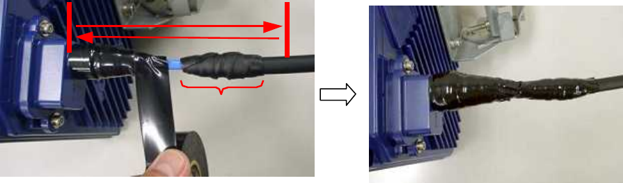
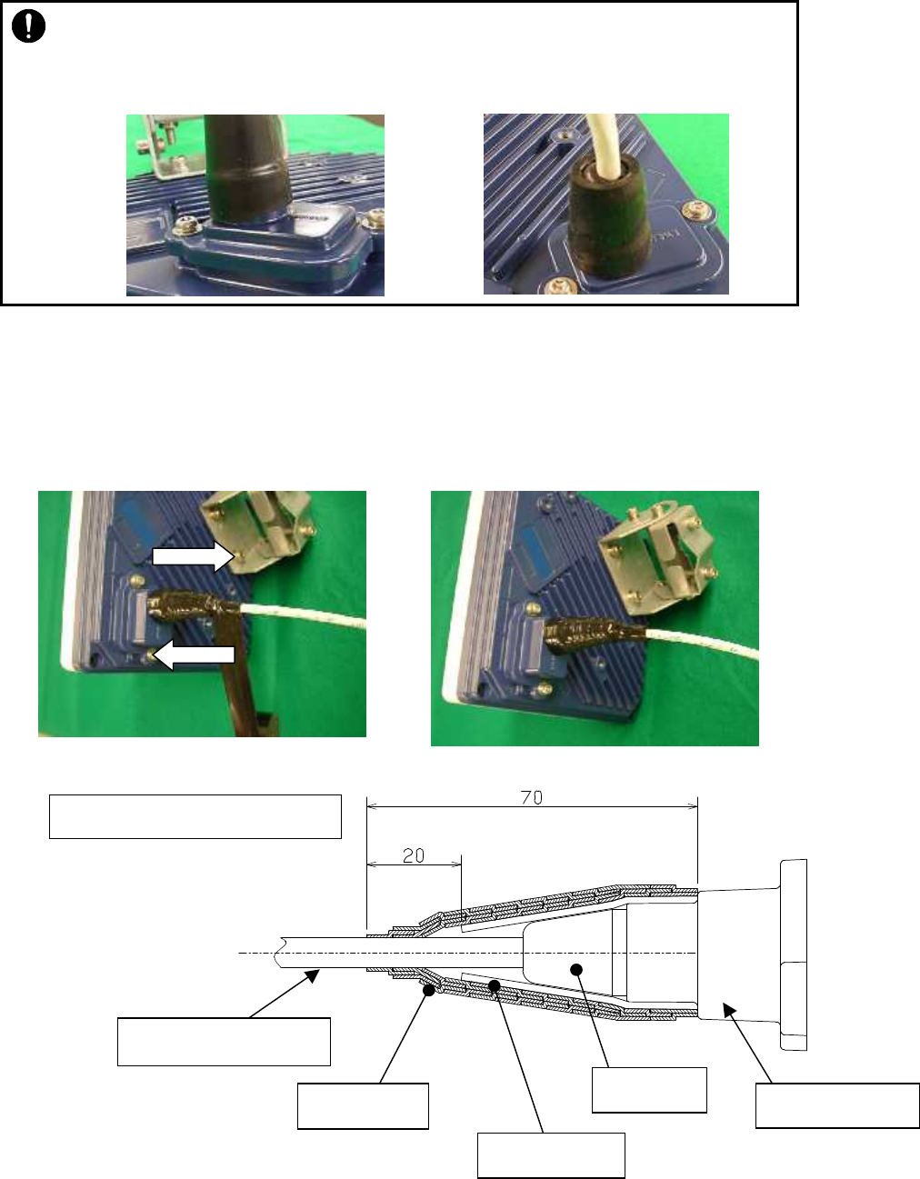
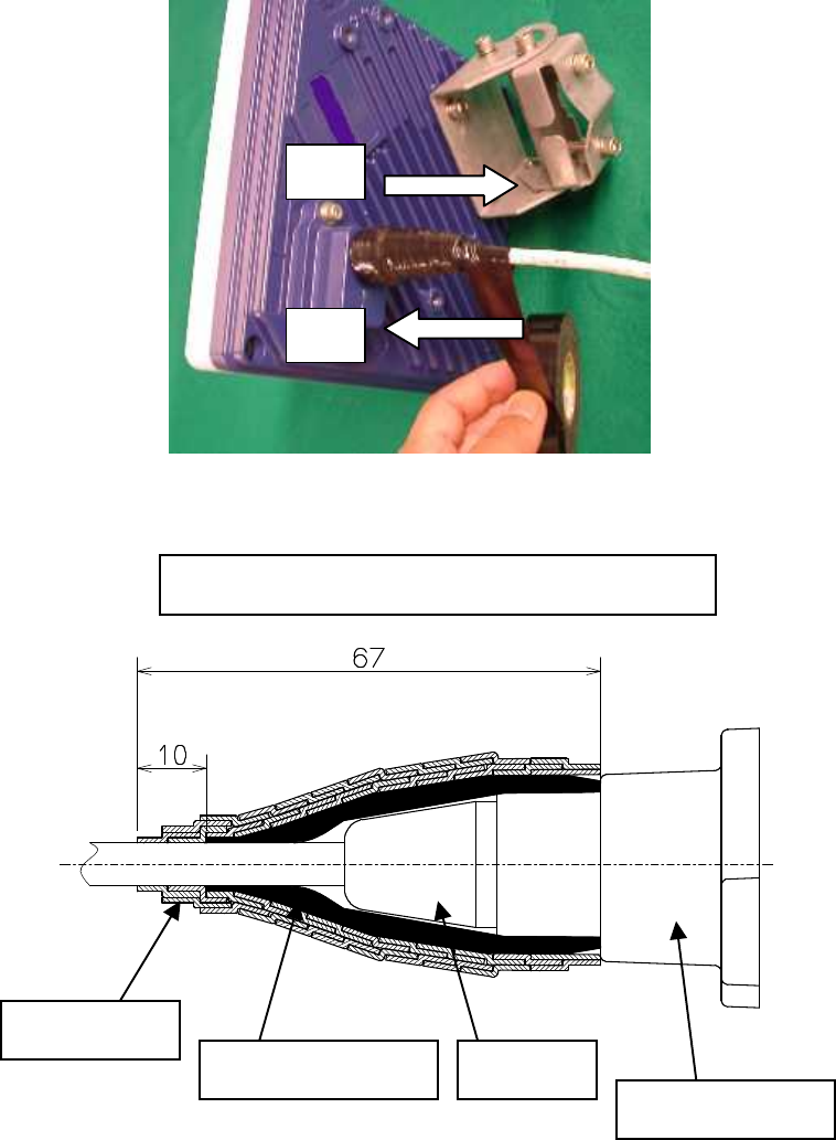
(6) Wrap the cable with PVC tape (for class 2 protection).
Apply the PVC tape so that the cold-shrinkable tube is completely hidden. Wrap the tape from
the small Lid of the WT to the Ethernet cable, overlapping half of the previous layer. Next,
reverse the wrapping direction and wrap one more time to the starting point.
・ Slanted mounting of the cold-
shrinkable tube as shown below will spoil the
waterproofing effect. If the top of the cold-
shrinkable tube is 5 mm or less from the
top of the spacer, this will also spoil the waterproofing effect.
NG
NG
6-103
Length of PVC tape wrapping
Small window
Ethernetcable cable
Spacer CS sleeve
PVC tape
65
22
6-104
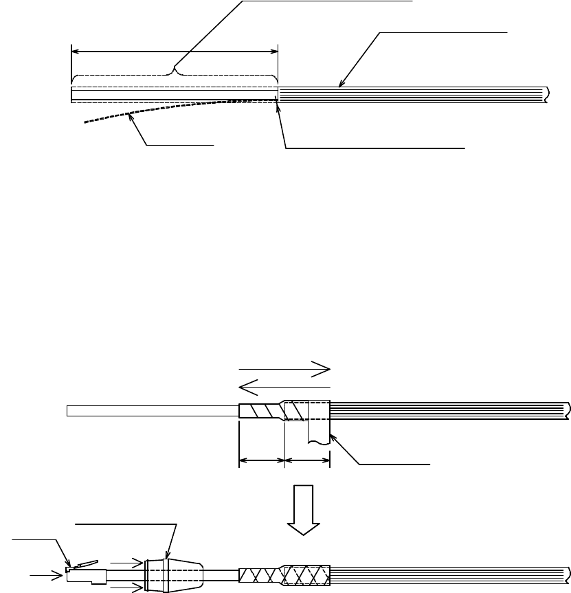
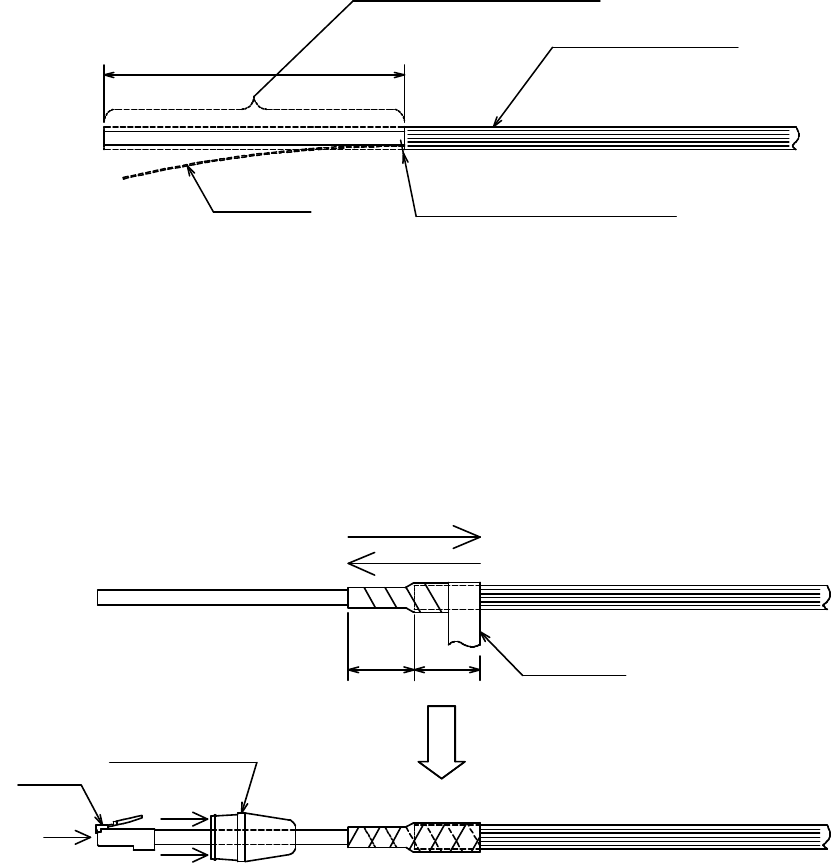
6.11. When you use the cable with the LAP sheath for outdoor
1.Processing of LAP sheath
- The LPA sheath is peeled off from the cable point to 120mm.
- It cuts it in the part peeled off when there is drain wire.
2.Processing of cutting part
- To prevent water being infiltrated in the wire, the self-bonding tape is rolled in the part
where the LAP sheath was peeled off as shown in the figure below.
- The Ether plug is installed with the normal temperature shrinkage sleeve and Spasa
passed.
3.Fixation of cable Ethernet、Installation of Spacer and normal temperature shrinkage sleeve
- See「6.9. Waterproofing WT small window」
4.Wrapping of PVC tape for protection
- It wraps until the self-bonding tape in the LAP sheath processing part is completely hidden
120mm
The cable with the LAP sheath
Drain
wire
is cut on the LAP sheath side.
Drain Wire
50mm
25
25
Self-bonding
Spacer
Connector
Push
6-105
from a small window to the Ethernet cable side by 1/2 coming in succession, and 1 return
round trip to the small window side.
Self-bonding tape part
6-106
START
END
Overlapping half og the previous layer
(cross-sectional view)
Ethernet cable
Spacer
Small window
Se
lf
-
bonding tape
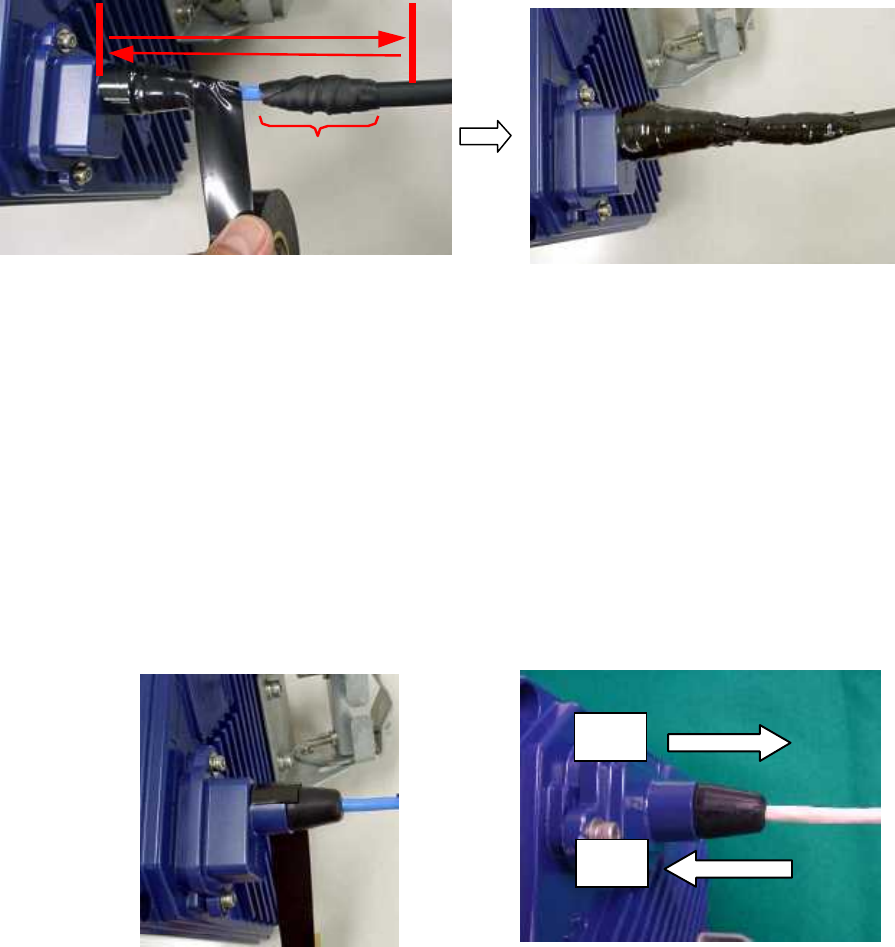
6.12. Waterproofing Without Using a Cold-Shrinkable Tube
If installing a cold-shrinkable tube fails, use off-the-shelf self-bonding tape to provide the
waterproofing.
(1) Securing the small Lid of the WT and the spacer
Using an appropriate length of self-bonding tape, wrap the tape around both the small Lid of
the WT (at its base) and spacer one complete turn. After one turn, wrap about seven turns
around the Ethernet cable by overlapping one-half of the previous turn. Reverse the wrapping
direction and wrap about another seven turns back to the small Lid.
・ For the stretching margin of self-bonding tape, see t
he instruction manual for the
product.
・ When wrapping self-
bonding tape, start at the base of the small window and end at
the end of the waterproof sleeve. Next, reverse the direction and end at the base of
the small window. This procedure makes an attracti
ve wrapping and improves the
waterproof effect by making any air pocketsless likely.
・ Overlapping the wraps also protects against air pockets.
・ Press evenly along the entire length of tape to remove air pockets.
・ Make sure that there are no air pockets between the self-
bonding tape and the small
window of the WT or the rubber bushing. Air pockets will degrade the waterproofing
effect.
6-107
(2) Wrapping protective PVC tape
Apply the protective PVC tape so that the cold-shrinkable tube is completely hidden. Wrap the
tape from the small Lid of the WT to the Ethernet cable, overlapping half of the previous layer.
Next, reverse the wrapping direction and wrap one more time to the starting point. Using the
PVC tape will guard the self-bonding tape against ultraviolet and other rays. The wrapping also
helps increase strength.
Key point: When wrapping PVC tape, be sure that the self-bonding tape is completely covered
for its protection.
PVC tape
Self-
bonding
Spacer
Small
Length of PVC tape used for
START
END
6-108
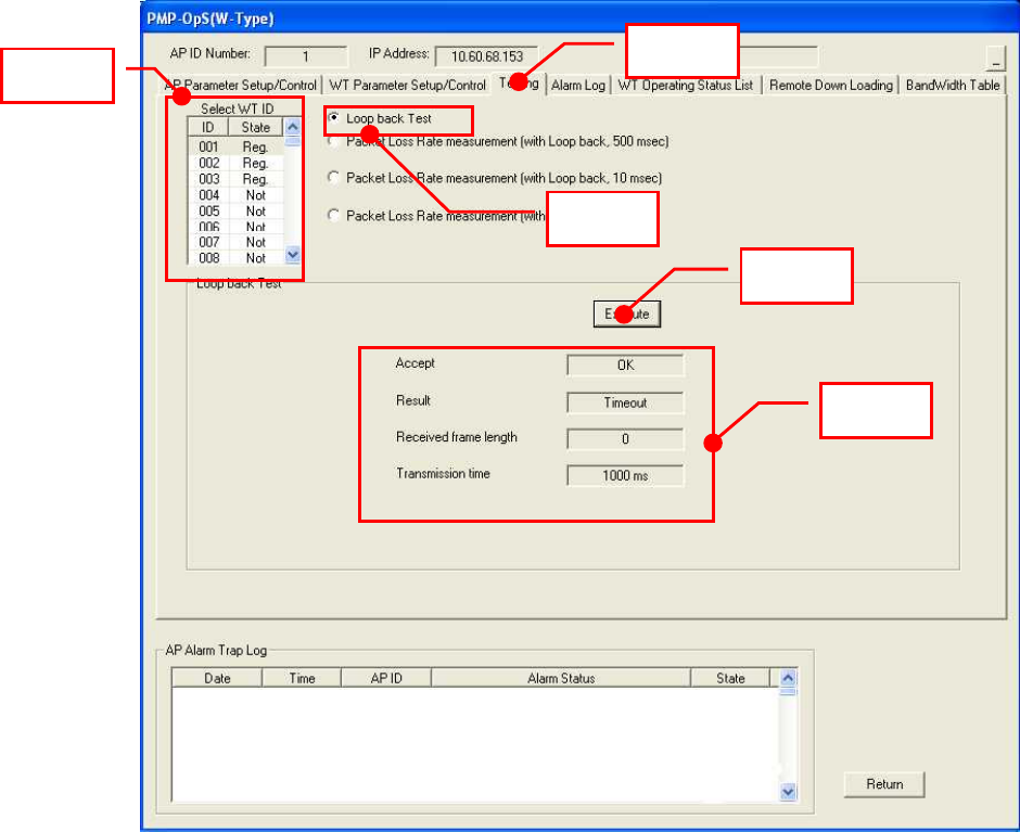
6.13. Testing
6.13.1. Perform a continuity test
Connect the OpS terminal to an AP, and run a loopback test with the following procedure:
Step 1: Click the Testing tab.
Step 2: Select a WT from the Select WT ID list.
Step 3: Select "Loop back Test."
Step 4: Click the Execute button to start the test.
Step 5: Check the test result:
- Accept : OK
- Result : OK
- Received frame length : 516
- Transmittion time : The result will vary depending on the distance.
Figure 6-54 Perform a continuity test
Step 1
Step 2
Step 3
Step 4
Step 5
6-109
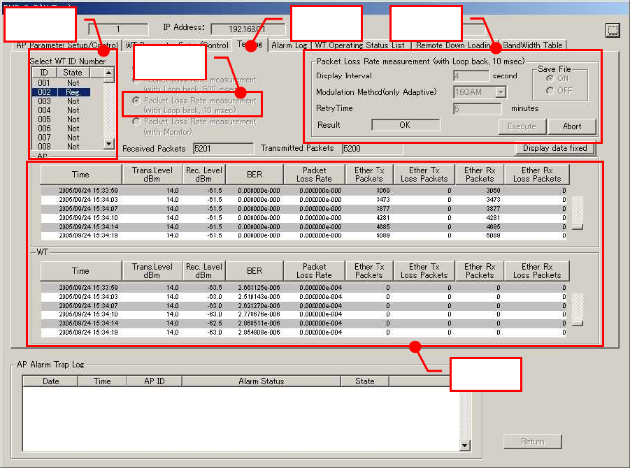
6.13.2. Measure the packet loss rate
Connect the OpS terminal to an AP and measure the packet loss rate with the following
procedure:
Step 1: Click the Testing tab.
Step 2: Select a WT from the Select WT ID list.
Step 3: Select the "Packet Loss Rate measurement (with Loop back, 10msec)" check
box.
Step 4: Specify the following settings, and click the Execute button to start the test.
- Display Interval : 4 seconds
- Modulation Method (only Adaptive) : Select the current modulation method
(check the WT Operation Status List in the OpS).
- Retry Time : 5 minutes
Step 5: Perform a time measurement and check the Packet Loss Rate column.
Figure 6-55 Measure the packet loss rate
Step 2
Step 1
Step 3
Step 4
Step 5

6-110
6.14. Check sheet of WT Construction
Check the operation of the WT using the check sheet below.
Test procedure
(A) LED operation test
- Remove the AC adapter (to turn off the power) and make sure that all the LEDs are off.
- Insert the AC adapter (to turn on the power) and check the states of the LEDs.
(B) Loopback test between the WT and the WT adapter
- Press the TEST switch on the WT adapter and make sure that the ETHER LED goes
out.
- Remove the cable from the WT adapter's PC port and make sure that the ETHER LED
goes out.
(C) Receive level
- Connect the WT Local Management Tool to the WT and measure the receive level.
(D) Position of the AP-RFU in the field of view after direction adjustment
- After the direction is adjusted, look into the scope of the Antenna direction adjustment
tool to visually check the position of the AP-RFU
Table 6-1 Check sheet
WT Serial number Test date
Test type Test condition Check item Pass/fail
Measured
value
Confirm that the POW LED on the WT adapter goes out.
-
Confirm that the ETHER LED on the WT adapter goes
out. -
Remove the AC
adapter.
Confirm that the ALM LED on the WT adapter goes out. -
Confirm that the POW LED on the WT adapter lights
green.
Confirm that the ETHER LED on the WT adapter flashes
green.
LED operation
test
Insert the AC
adapter.
Confirm that the ALM LED on the WT adapter flashes at
1-second intervals and then goes out.
Press the TEST
switch on the WT
adapter.
Confirm that the ETHER LED on the WT adapter goes
out. -
Loopback test
between WT and
WT adapter Remove the
cable from the
WT adapter's PC
port.
Confirm that the ETHER LED on the WT adapter goes
out.
Receive level − Connect the WT Local Management Tool to the WT and
measure the receive level. dBm
7-111
7. CONSTRUCTING A POINT-TO-POINT SYSTEM
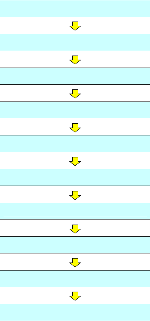
7.1. Overview(WT Construction flow)
Connecting the WT Local Management Tool
Configure the WT(master)
Configure the WT(slave)
Installing the WT
Installing the WT Adapter(master/slave)
Connecting Cables to the WT(master/slave)
Waterproofing WT small window
Testing
Check sheet of Point to Point Construction
Finish
7-112
7.2. Connecting the WT Local Management Tool
Connect the local management tool terminal to the PC port of the WT adapter (Figure 7-1) using a
straight Ethernet cable.
Figure 7-1 Connection
Master
IP address: 192.168.1.200
Subnet mask: 255.255.255.0
Slave
IP address: 192.168.1.201
Subnet mask: 255.255.255.0
initial values
IP address:192.168.1.100
Subnet mask:255.255.255.0
Ethernet cable (Straight)
WT adapter
AC Adapter AC100∼240V
DC24V
local management tool(PC)
Ethernet cable (Straight)
・ When changing the IP addr
ess of the unit, set the IP address of the local
management tool (PC) to an IP address belonging to the same network.
・
When changing the IP address of the unit, restart the power of the hub if the unit is
connected to the local management tool (PC) via a hu
b (because MAC address
learning may fail and the connection may be dropped).
7-113
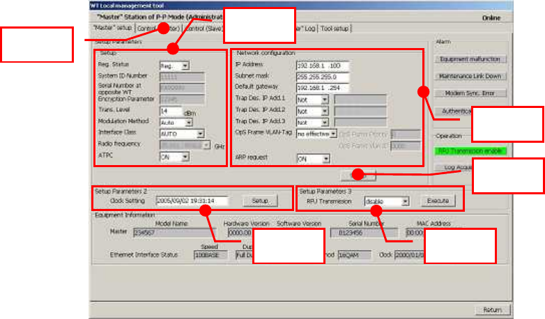
7.3. Configure the WT(master)
Change the WT’s mode from P-MP to P-P(matser).
On the Setup screen in the WT Local Management Tool (Master in P-P mode, Administrator),
specify the settings in the following procedure:
Step 1: Select the ”Master” setup tab.
Step 2: Specify the settings under Setup for Setup Parameters.
- System ID Number: Set the system ID number.
- Serial number at opposite WT: Set the serial number at the opposite WT.
- Encryption Parameter: Set the encryption parameter.
- Trans. Level: Set the transmission level.
- Modulation Method: Set the modulation method to QPSK, 16QAM, or AUTO.
- Interface Class: Set the interface class to AUTO or 10BASE.
- Radio Frequency: Set the radio frequency.
- Reg. Status: Set the registration status to Reg.
Step 3: Set the Network configuration for Setup Parameters.
- IP Address: Set the IP address.
- Subnet mask: Set the subnet mask.
- Default gateway: Set the default gateway.
- Trap Des. IP Add1: Set "Reg." or "Not" and trap destination IP address 1. As required,
you can also set Trap Des. IP Add2, and Trap Des. IP Add3.
- OpS Frame Priority: Set the OpS frame priority.
- OpS Frame Vlan-ID: Set the OpS frame Vlan-ID.
- ARP Request: Set the ARP request to ON or OFF.
Step 4: Click the Setup button.
Step 5 Make a clock setting in Setup Parameters2 and click the Setup button.
Step 6 Set RFU Transmission (Enable) in Setup Parameters3 and click the Execute button.
7-114
Figure 7-2 Configure the WT(master)
Step1
Step4
Step3
Step2
Step5
Step6
7-115
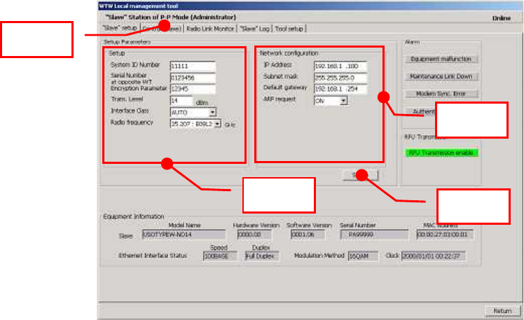
7.4. Configure the WT(slave)
Change the WT’s mode from P-MP to P-P(slave).
On the Setup screen in the WT Local Management Tool (Slave in P-P mode, Administrator),
specify the settings in the following procedure:
Step 1: Select the ”Slave” setup tab.
Step 2: Specify the settings under Setup for Setup Parameters.
- System ID Number: Set the system ID number.
- Serial number at opposite WT: Set the serial number at the opposite WT.
- Encryption Parameter: Set the encryption parameter.
- Trans. Level: Set the transmission level.
- Interface Class: Set the interface class to AUTO or 10BASE.
- Radio Frequency: Set the radio frequency.
Step 3: Set the Network configuration for Setup Parameters.
- AP IP Address: Set the AP IP address.
- Subnet mask: Set the subnet mask.
- Default gateway: Set the default gateway.
- ARP Request: Set the ARP request to ON or OFF.
Step 4: Click the Setup button.
Figure 7-3 Configure the WT(slave)
Step1
Step4
Step3
Step2
7-116
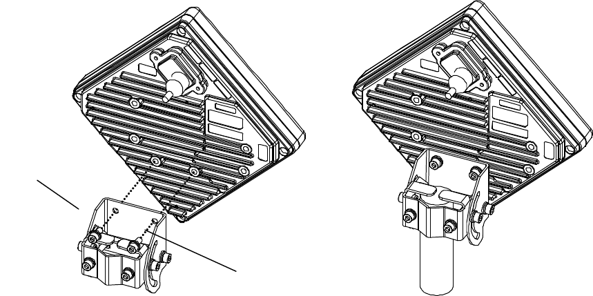
(a)
(b)
7.5. Installing the WT
7.5.1. Installing the WT(master/slave)
Step1 Attach the WT mounting bracket to the WT using the bolts(a)and (b).
You can orient the WT either for vertical or horizontal polarization.
Step2 Secure the WT mounting bracket to the pole using the bolts.
Applicable pole diameter: From Φ31.8mm to Φ34mm
Fi
gure 7-4 Installing the WT
7-117
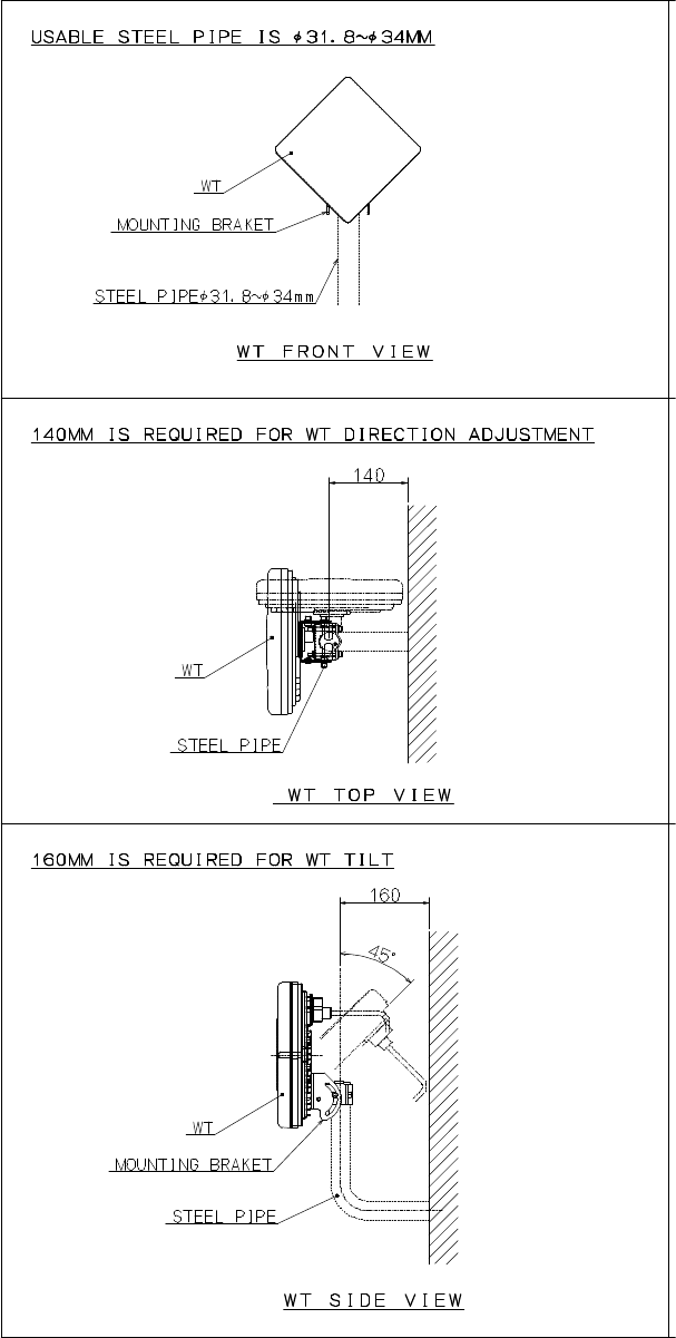
A builder prepares a steel pipe by the installation place (a wall, a pole or etc.), and it install.
The required space of installation is shown below.
Figure 7-5 The required space of installation
7-118
7.5.2. Example of Installing the WT
(1) On a metal fence
Figure 7-6 Installing on a metal fence
(2) On a house wall
Figure 7-7 Installing on a house wall
MOUNTING
BRACKET
FIXING
BRACKET
METAL FENCE
WT
EAVES
WT
MOUNTING
BRACKET
FIXING
BRACKET
WALL
7-119
7.5.3. Setting the WT for Vertical or Horizontal Polarization
Rotate the antenna ninety degrees to choose between vertical or horizontal polarization
For vertical polarization, position TOP V at the top.
For horizontal polarization, position TOP H at the top.
Figure 7-8 Vertical Polarization
Figure 7-9 Horizontal Polarization
Horizontal polarization
TOP V
TOP H
ETH E R
INPUT :
SER.NO :
MAC :
.: : : : :
MADE IN JAPAN
DC24V 0.7A
TYPEW−WT<EL0>
TOP H
Vertical polarization
TOP V
TOP H
ETHER
INPUT :
SER.NO :
MAC :
.: : : : :
MADE IN JAPAN
TYPEW−WT<EL0>
DC24V 0.7A
TOP V

7-120
7.6. Installing the WT (External Antenna)
7.6.1. Installing the WT (ExternalΦ30cm Antenna)
1. Φ30cm antenna installation procedure
1) According to the antenna manual of RADIO WAVES, INC., set it up on the pole. (Figure 7-10)
2) Spread specified grease on the O-ring.
The spreading method depends on the
manual. (Figure 7-11)
Figure 7-10 Φ30cm antenna
Figure 7-11
2. WT installation procedure
Attach the antenna adaptor to the WT with the O-ring using four M3 screws. (Figure 7-12 & Figure 7-13)
Tightening torque:57 N・cm
Figure 7-12
M3 screws
O-ring
Adaptor
WT
O-ring

7-121
Figure 7-13
3. Attachment of the WT to the antenna
1) V(ertical) polarization
When using the V polarization, the guide pin of the WT should be turned to right above and inserted into
the V guide hole of the plate. (Figure 7-14 & Figure 7-15)
Figure 7-14
Figure 7-15
V polarization
Guide pin
I C: 76 8 B−N T G3 37 注 5
TOPV
T OP H
ET H ER
IN P UT:
S E R . NO:
M A C :
.: : : : :
MA D EI N JAP A N
DC24V0.7A
TYPEW−WT < 注 1>
F C CID:C KENTG33 7 − 注 1
WT EL2
MO D E L: N T G −3 3 7 注2 R
V guide hole
Plate
After installing the adaptor

7-122
After inserting the guide pin of the WT into the guide hole, presses the WT to the plate.
While you are pressing the WT, you must be tightening the four M5 screws. (Figure 7-16)
Tightening torque:265 N・cm
Figure 7-16
2) H(orizontal) polarization
When using H polarization, the guide pin of the WT should be rotated to the right and inserted into the H
guide hole of the plate. (Figure 7-17 & Figure 7-18)
Figure 7-17 Figure 7-18
I C: 7 68B −N TG 33 7 注5
TOPV
TOPH
E T H E R
INPUT:
SER.NO:
MAC :
.: : : : :
MADEINJAPAN
DC24V0.7A
TYPEW−WT<注1>
FCCID:CKENTG337−注1
WT E L2
M OD E L : N TG − 33 7注 2 R
Plate
M5 screws
Guide pin
I C: 7 68 B− N TG 33 7 注5
TOPV
TOPH
E T H ER
INPUT:
SER.NO :
MAC:
.:::: :
MADEI N J A P A N
DC24V0.7A
TY P EW−WT < 注1>
F C CI D :CKE N TG 3 3 7 − 注 1
W T EL 2
M O DE L : N T G− 3 3 7 注 2 R
Plate
H guide hole
7-123
After inserting the guide pin of the WT into the guide hole, presses the WT to the plate.
While you are pressing the WT, you must be tightening the four M5 screws. (Figure 7-19)
Tightening torque:265 N・cm
Figure 7-19
I C:7 6 8B −NTG 337 注5
TOPV
TOPH
E T H E R
INPUT:
SER.NO:
MAC:
.:::::
MADEINJAPAN
DC24V0.7A
TY PEW−WT<注1>
FCCID:CKENTG337−注 1
WT EL 2
MO DE L : N TG− 33 7 注2 R
Plate
M5 screws
7-124
7.6.2. Installing the WT (ExternalΦ60cm Antenna)
1. Φ60cm antenna installation procedure
1) According to the antenna manual of RADIO WAVES, INC., set it up on the pole. (Figure 7-20)
2) Spread specified grease on the O-ring.
The spreading method depends on the
manual. (Figure 7-21)
Figure 7-20 Φ30cm antenna
Figure 7-21
2. WT installation procedure
Attach the antenna adaptor to the WT with the O-ring using four M3 screws. (Figure 7-22 & Figure 7-23)
Tightening torque:57 N・cm
Figure 7-22
M3 screws
O-ring
Adaptor
WT
O-ring

7-125
Figure 7-23
3. Attachment of the WT to the antenna
1) V(ertical) polarization
When using the V polarization, the guide pin of the WT should be turned to right above and inserted into
the V guide hole of the plate. (Figure 7-24 & Figure 7-25)
Figure 7-24
Figure 7-25
V polarization
Guide pin
After installing the adaptor
V guide hole
Plate
TOPV
TOP H
ETHER

7-126
After inserting the guide pin of the WT into the guide hole, presses the WT to the plate.
While you are pressing the WT, you must be tightening the four M5 screws. (Figure 7-26)
Tightening torque:265 N・cm
Figure 7-26
2) H(orizontal) polarization
When using H polarization, the guide pin of the WT should be rotated to the right and inserted into the H
guide hole of the plate. (Figure 7-27 & Figure 7-28)
Figure 7-27 Figure 7-28
Guide pin
Plate
M5 screws
TOPV
TOPH
ET H E R
W T EL 2
Plate
H guide hole
TO P V
T O P H
E T H E R
W T EL 2
7-127
After inserting the guide pin of the WT into the guide hole, presses the WT to the plate.
While you are pressing the WT, you must be tightening the four M5 screws. (Figure 7-29)
Tightening torque:265 N・cm
Figure 7-29
Plate
M5 screws
TOPV
TOPH
E T H E R
WT E L 2
7-128
7.7. Adjusting the Direction of the WT
7.7.1. Adjusting the Direction of the WT
This section describes the procedure for adjusting the antenna direction when a Point-to-Point
System is used.
When adjusting the direction of the WT antenna, use the “Antenna direction adjustment tool”
together with the WT Local Management Tool.
Step 1: Connection between WT (master/slave) and WT Local Management Tool and display the
Receiving Level.
See Subsection 7.7.1.1
- Method of adjustment for near-distance installation
If circuit design calls for a receive level of -35 dBm or higher, you need to reduce the
transmission level according to the following procedure:
WT (Master) Trans Level : 14dBm → -6dBm (see Subsection 7.7.1.1 (4))
WT (Slave) Trans Level : 14dBm → -6dBm (see Subsection 7.7.1.1 (4))
Step 2: Rough adjustment for the WT (Master)
- Install the Antenna direction adjustment tool.
- See Subsection 7.7.1.2
- Remove the Antenna direction adjustment tool.
Step 3: Rough adjustment for the WT (Slave)
- Install the Antenna direction adjustment tool.
- See Subsection 7.7.1.2
- Remove the Antenna direction adjustment tool.
Step 4: Fine adjustment for the WT (Slave)
- See Subsection 7.7.1.3
Step 5: Fine adjustment for the WT (Master)
- See Subsection 7.7.1.3
Step 6: Verification
- After fine adjustment, use the WT Local Management Tool to final check the receive level.
If the receive level value is within the standard range, the procedure for adjusting the
antenna direction has been completed.
If the receive level value is lower than a standard value, you need to perform Steps 4 and
5 again.
Step 7: Exit the WT Local Management Tool, and remove the cable from the WT adapter.
7-129
7.7.1.1. Connecting the WT Local Management Tool
(1) As shown in Figure 7-30, connect the WT Local Management Tool (PC) to the WT adapter.
Figure 7-30 Connecting the WT Local Management Tool
(2) Measuring the receive level the WT (master in P-P mode)
- Start the WT Local Management Tool and select P-P mode.
- On the Radio Link Monitor screen in the master station in P-P mode, measure the
"Receiving Level" value.
The procedure is shown in Figure 7-31.
Figure 7-31 Measuring the Receive Level (Master)
・ The minimum display interval is 1
second, and you need to adjust the antenna
direction slowly.
Master
IP address: 192.168.1.200
Subnet mask: 255.255.255.0
Slave
IP address: 192.168.1.201
Subnet mask: 255.255.255.0
WT adapter
AC Adapter AC100∼240V
DC24V
local management tool(PC)
Ethernet cable (Straight)
7-130
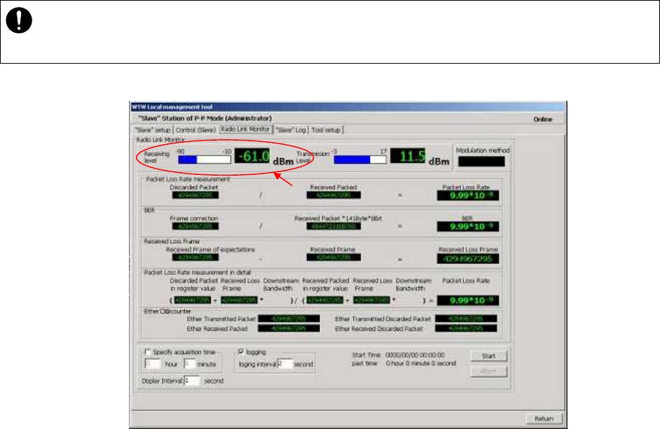
(3) Measuring the receive level of the WT (slave in P-P mode)
- Start the WT (slave in P-P mode) and select P-P mode.
- On the Radio Link Monitor screen in the slave station in P-P mode, measure the
"Receiving Level" value.
The procedure is shown in Figure 7-32.
Figure 7-32 Measuring the Receive Level (Slave)
・
The minimum display interval is 1 second, and you need to adjust the antenna
direction slowly.
7-131
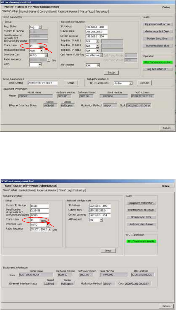
(4) Method of adjustment for near-distance installation
If circuit design calls for a receive level of -35 dBm or higher, use the following procedure:
- Start the WT Local Management Tool and select P-P mode.
- On the Master Setup screen in the master station in P-P mode, change "Trans.Level" from
14[dBm] to -6[dBm]. After the change, click the SETUP button.
The procedure is shown in Figure 7-33.
Figure 7-33 Setting "Trans.Level" for the WT (Master)
- On the Slave Setup screen in the slave station in P-P mode, change "Trans.Level" from
14[dBm] to -6[dBm]. After the change, click the SETUP button.
The procedure is shown in Figure 7-34.
Figure 7-34 Setting "Trans.Level" for the WT (Slave)
OFF
7-132
Direction adjustment tool
TOP V
(a)
TOP H
Direction adjustment tool
(a)
(f) (e)
(d)
(b) (C)
7.7.1.2. Roughly Adjusting the Direction
Step1 As shown inFigure 7-35 and Figure7-36, use the wing bolt (a) to attach the Antenna
direction adjustment tool.
Step2 As shown in Figure 7-37, loosen the hexagonal socket head bolts (b) and (c) securing the
mounting bracket and swing the antenna left or right. Adjust the antenna approximately for
the WT direction and finger-tighten the bolts (b) and (c).
Step3 As shown in Figure 7-38, loosen the bolts (d), (e), and (f) and tilt the antenna up or down.
Perform vertical-direction adjustment so that the WT of the opposite station can be seen
through the scope of the Antenna direction adjustment tool.
.
Figure 7-35 How to Install Direction Adjustment tool
when the antenna type is the horizontal polarization
Figure7-36 How to Install Direction Adjustment tool
when the antenna type is the vertical polarization
In Figure 7-37 and Figure 7-38 is an example when the antenna type is the horizontal polarization.
Figure 7-37 Rough-adjusting Horizontal Direction Figure 7-38 Rough-Adjusting the Vertical Direction
・ Never look at the sun directly. Doing so may seriously damage the eyes.
7-133
7.7.1.3. Finely Adjusting the Direction
Step 1: Horizontal direction
As shown in Figure 7-39, loosen the hexagonal socket head bolts (a) and (b) securing the
mounting bracket and swing the antenna left or right. Adjust the antenna direction so that the
receive level indicates the maximum value, and finger-tighten the bolts (a) and (b).
Step 2: Vertical direction
As shown in Figure 7-40, loosen the hexagonal socket head bolts (c), (d), and (e) securing the
mounting bracket and tilt the antenna up or down. Adjust the antenna direction so that the
receive level indicates the maximum value. Tighten the bolts at a point showing the maximum
receive level (tightening torque: 8.5N•m). Tighten the bolts (c), (d), and (e) and make sure that
the point showing the maximum receive level is maintained. This concludes the procedure for
vertical-direction adjustment.
Step 3: Horizontal direction
Finely adjust the horizontal direction by slightly loosening the bolts (a) and (b) again. Once
again, locate the point where the receive level reaches the maximum value and hold that point.
Finally, tighten the bolts (a) and (b) (tightening torque: 8.5N•m) while making sure that the
point showing the maximum receive level is maintained. This concludes the procedure for
horizontal-direction adjustment.
The figures show examples of horizontal polarization setup.
Figure 7-39 Finely Adjusting the Horizontal Direction Figure 7-40 Finely Adjusting the Vertical Direction
(a)
(b)
(d)
(c)
(e)
Note : When adjusting the antenna direction
When adjusting the direction, you m
ight mistakenly take the antenna's side lobe as
the maximum receive
level. For fine adjustment, therefore, you should move the
antenna some more after the receive level has reached the maximum value to make
sure that you have not caught a side lobe.
7-134
7.7.2. The receive level and the distance
In a point-to-point system, the receiving level at clear sky and the distance are related as shown in
Figure 7-41.
Figure 7-41 Receiving Level and Distance (QPSK)
-90
-80
-70
-60
-50
-40
-30
-20
-10
0
1 10 100 1000 10000
Distance[m]
Receiving Level [dBm]
Transmission level (QPSK) 14 [dBm] Free space loss Lp[dB]
Frequency 26 [GHz]
Antenna gain[TX+RX]
TX WT Antenna Gain:31dBiTYP
RX WT Antenna Gain:31dBiTYP
62 [dBi]
λ
πd
Lp 4
log20
Hzf
mc
mλ
Receiving level
Maximum receiving level
Minimum receiving level
7-135
Figure 7-42 Receiving Level and Distance (16QAM)
-80
-70
-60
-50
-40
-30
-20
-10
0
1 10 100 1000 10000
Distance[m]
Receiving Level [dBm]
Transmission level (16QAM) 14 [dBm] Free space loss Lp[dB]
Frequency 26 [GHz]
Antenna gain[TX+RX]
TX WT Antenna Gain:31dBiTYP
RX WT Antenna Gain:31dBiTYP
62 [dBi]
λ
πd
Lp 4
log20
Hzf
mc
mλ
Maximum receiving level
Minimum receiving level
Receiving level
7-136
7.8. Installing the WT Adapter(master/slave)
WT Adapter is installed in indoor
It is an example of installing the appended wood screw.
Screw into the mounting position the wood screw that comes with the WT adapter, leaving 2 mm.
Hook the WT adapter on the wood screw.
Figure 7-43 Installing the WT Adapter on the Wall
Wood Screw

7-137
7.9. Connecting Cables to the WT(master/slave)
Use an Ethernet cable (straight) to connect the WT and the WT adapter as shown in Figure 7-44.
Figure 7-44 Connecting Cables to the WT
MDI
MDI-X
WT adapter
Cold-shrinkable tube
Small
Lid
Rubber
Ethernet cable (Straight)
You will need a Torx screwdriver (VESSEL
T20H-120) to open the small cover of the WT
AC adapter
User Terminal
WT
Cold-shrinkable tube
Spacer
Sm
all
Window

7-138
(1) Connected cable between WT and ANT port of WT adapter
(2) Connect the user terminal to PC port of WT adapter
(3) Connect the AC adapter to DC port to the WT adapter
Cable
Cable type Ethernet cable for outdoor,straight
Range of applicable outer
diameter φ5.0 mm∼5.7mm
Cable length 50m (maximum)
Connector of both side
Shape RJ-45
Cable connection Straight connection
- WT : MDI
- ANT port of WT adapter : MDI-X
An Ethernet cable has eight signal lines. Four lines are used to carry
Ethernet signals. The remaining four lines are used as power lines and
LED control lines.
Interface
Interface 10BASE-T/100BASE-TX
Connector
Shape RJ-45
Pin assign Ethernet signal(MDI-X)
Cable
Communication terminal Cable connection
PC straight
HUB crossover
ROUTER straight
・
Never connect your personal computer to the ANT port of the WT adapter. Doing so may
damage your personal computer.
・
The cable connecting between the WT and WT adapter carries 24 VDC for the WT in
addition to Ethernet signals. Before unplugging
the cable connecting between the WT and
WT adapter, make sure to unplug the DC jack of the WT adapter to turn the power off.
Otherwise, the unit may be damaged.
・
When closing the small window, make sure that the rubber packing of the small window is
free from any foreign matter.
・
The cable connecting the WT and WT adapter is a straight cable. Wrong connection may
damage the unit.
・ The Equipment for connection to WT adapter PC-interface(RJ-
45) shall be appropriate to
connect to TNV-1 circuits.
・ For the connecti
on WT adapter to WT and a cable suitable for outdoor use shall be
installed.
7-139
7.10. Waterproofing WT small window
(1) Pass the Ethernet cable through the cold-shrinkable tube (a) from the bonded portion of the
spiral tube. Pay attention to the insertion direction (Figure 7-46).
Applicable LAN cable diameter: 5.0 mm to 5.7 mm
Figure 7-45 Figure 7-46
(2) Connect the Ethernet cable to the WT (Figure 7-47).
(3) Using cable ties (c) or the like, secure the Ethernet cable to the supporting bracket. Attach the
cable ties 70 to 100 mm from the end of the supporting bracket. The cable is approximately
300 mm long measured from the cable joint (with a diameter of approximately 200 mm) to the
first cable tie (Figure 7-48).
Figure 7-47 Figure 7-48
・
Never allow the inside of the small window to become wet. Dampness may cause a
malfunction. Connect the Ethernet cable perpendicular to the WT. Failure to do so
will spoil the waterproofing effect, resulting in a device malfunction.
Bent cable
Cable perpendicular
to the WT
OK
(c Cable ties
φ200mm
300mm
(d) Spacer
(a) Cold-shrinkable tube
Pay attention to the irection
(b) Ethernet cable
Bonding portion of the spiral
tube for the cold-shrinkable
Components of CS sleeve
(e) Spiral tube
NG
7-140
(4) Mounting spacer (d)
- Mount the spacer on the Ethernet cable
- Make sure that the spacer is fully inserted in the small Lid of the WT (Figure 7-50).
Figure 7-49 Figure 7-50
(5) Mounting cold-shrinkable tube (a)
- Place the cold-shrinkable tube on the spacer and small Lid (Figure 7-51).
- Butt the end of the cold-shrinkable tube against the base of the small Lid. Pulling white
spiral tube (e) to the very edge of the cold-shrinkable tube eases the subsequent
procedure (Figure 7-51).
- Pull the spiral tube to mount the edge of the cold-shrinkable tube on the small Lid (Figure
7-52). Make sure that there is no gap between the cold-shrinkable tube and the base of
the small Lid and between the spacer and the small Lid.
- Pull the spiral tube to mount the cold-shrinkable tube, paying attention so the spacer is
not lifted (Figure 7-53 and Figure 7-54). Make sure that the spacer is not protruded from
the cold-shrinkable tube. The top of the cold-shrinkable tube should be 5 mm or less from
the top of the spacer.
Figure 7-51 Figure 7-52
Figure 7-53 Figure 7-54
(d)
Inserted
Spacer
・
Insert the spacer into the small window fully. Partial insertion of the spacer will spoil the
waterproofing effect.
7-141
Length of PVC tape wrapping
Small window
(6) Wrap the cable with PVC tape (for class 2 protection).
Apply the PVC tape so that the cold-shrinkable tube is completely hidden. Wrap the tape from
the small Lid of the WT to the Ethernet cable, overlapping half of the previous layer. Next,
reverse the wrapping direction and wrap one more time to the starting point.
・ Slanted mounting of the cold-
shrinkable tube as shown below will spoil the
waterproofing effect. If the top of the cold-
shrinkable tube is 5 mm or less from the
top of the spacer, this will also spoil the waterproofing effect.
NG
NG
Ethernetcable cable
Spacer
CS sleeve
PVC tape
7-142
7.11. When you use the cable with the LAP sheath for outdoor
1.Processing of LAP sheath
- The LPA sheath is peeled off from the cable point to 120mm.
- It cuts it in the part peeled off when there is drain wire.
2.Processing of cutting part
- To prevent water being infiltrated in the wire, the self-bonding tape is rolled in the part
where the LAP sheath was peeled off as shown in the figure below.
- The Ether plug is installed with the normal temperature shrinkage sleeve and Spasa
passed.
3.Fixation of cable Ethernet、Installation of Spacer and normal temperature shrinkage sleeve
- See「6.9. Waterproofing WT small window」
4.Wrapping of PVC tape for protection
- It wraps until the self-bonding tape in the LAP sheath processing part is completely hidden
120mm
The cable with the LAP sheath
Drain
wire
is cut on the LAP sheath side.
Drain Wire
50mm
25
25
Self-bonding
Spacer
Connector
Push
7-143
from a small window to the Ethernet cable side by 1/2 coming in succession, and 1 return
round trip to the small window side.
7.12. Waterproofing Without Using a Cold-Shrinkable Tube
If installing a cold-shrinkable tube fails, use off-the-shelf self-bonding tape to provide the
waterproofing.
(1) Securing the small Lid of the WT and the spacer
Using an appropriate length of self-bonding tape, wrap the tape around both the small Lid of
the WT (at its base) and spacer one complete turn. After one turn, wrap about seven turns
around the Ethernet cable by overlapping one-half of the previous turn. Reverse the wrapping
direction and wrap about another seven turns back to the small Lid.
START
END
Self-bonding tape part
7-144
(2) Wrapping protective PVC tape
Apply the protective PVC tape so that the cold-shrinkable tube is completely hidden. Wrap the
tape from the small Lid of the WT to the Ethernet cable, overlapping half of the previous layer.
Next, reverse the wrapping direction and wrap one more time to the starting point. Using the
PVC tape will guard the self-bonding tape against ultraviolet and other rays. The wrapping
also helps increase strength.
Key point: When wrapping PVC tape, be sure that the self-bonding tape is completely covered
for its protection.
・ For the stretching margin of self-bon
ding tape, see the instruction manual for the
product.
・ When wrapping self-
bonding tape, start at the base of the small window and end at
the end of the waterproof sleeve. Next, reverse the direction and end at the base of
the small window. This procedure m
akes an attractive wrapping and improves the
waterproof effect by making any air pocketsless likely.
・ Overlapping the wraps also protects against air pockets.
・ Press evenly along the entire length of tape to remove air pockets.
・ Make sure that there are no air pockets between the self-
bonding tape and the small
window of the WT or the rubber bushing. Air pockets will degrade the waterproofing
effect.
Overlapping half og the previous layer
(cross-sectional view)
Ethernet cable
Spacer
Small window
Self-bonding tape
7-145
START
END
PVC tape
Self- bonding tape
Spacer
Small window
Length of PVC tape used for wrapping
7-146
7.13. Testing
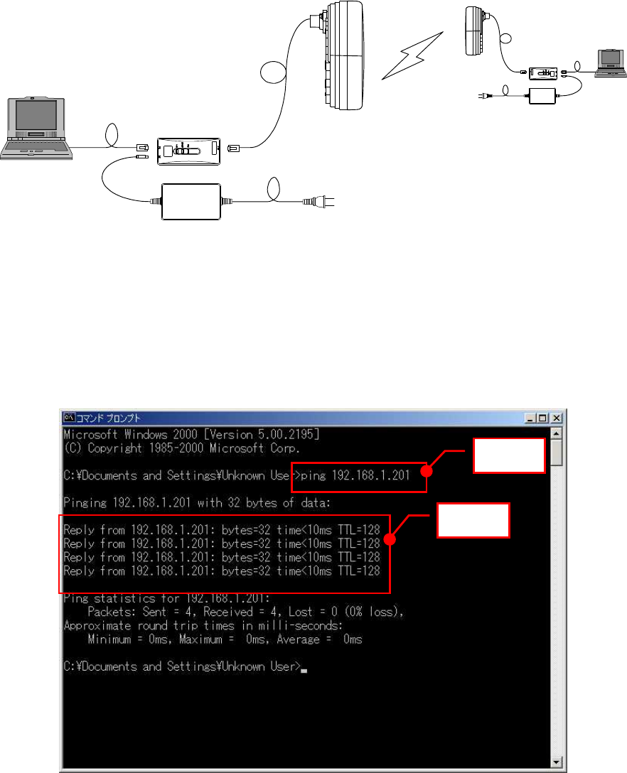
7.13.1. Ping test
Connect the WT and the PC as shown in Figure 7-55. Use the PC to perform a ping test in the
following procedure.
WT adapter
AC Adapter AC100∼240V
DC24V
PC Ethernet cable (Straight)
Master Slave
Figure 7-55 Ping Test System Diagram
Step 1: Start the Windows command prompt.
Step 2: Type the following command and press the Return key.
Ping xxx.xxx.xxx.xxx, where xxx.xxx.xxx.xxx shows the IP address of the
opposite PC.
Step 3: After the command is run, check that a reply as shown in Figure 7-56 returns.
Figure 7-56 Ping Test
Step 2
Step 3
7-147
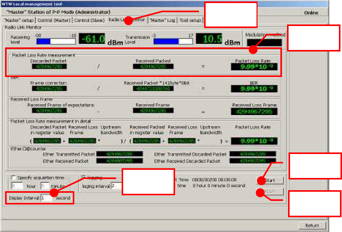
7.13.2. Measure the packet loss rate (with WT Local
mnagement tool)
Connect the WT Local Management Tool and measure the packet loss rate in the following
procedure:
Step 1: Start the WT Local Management Tool and select P-P mode.
Step 2: Select the Radio Link Monitor tab.
Step 3: Set "Display Interval" to 1.
Step 4: Click the Start button to start traffic measurement.
Step 5: After traffic measurement for any length of time, click the Abort button to end
traffic measurement.
Step 6: Check "Packet Loss Rate."
Figure 7-57 Measure the packet loss rate
Step4
Step2
Step3
Step5
Step6
7-148
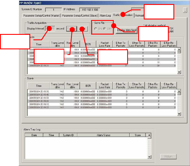
7.13.3. Measure the packet loss rate (with OpS)
Connect the OpS terminal to the WT (Master) and measure the packet loss rate in the following
procedure.
Step 1: Select the Traffic Information tab.
Step 2: Set "Display Interval" under "Traffic Acquisition."
Step 3: Select Save File as ON or OFF.
Step 4: Click the Execute button under "Traffic Acquisition" to start traffic measurement.
Step 5: After traffic measurement for any length of time, click the Abort button under
"Traffic Acquisition" to end traffic measurement.
Step 6: Check "Packet Loss Rate."
Figure 7-58 Measure the packet loss rate
Step 2
Step 1
Step 3
Step 4
Step 5

7-149
7.14. Check sheet of Point to Point Construction
Check operation of the WT (Master/Slave) using the check sheet below.
Test procedure
(A) LED operation test
- Remove the AC adapter (to turn off the power) and make sure that all the LEDs go out.
- Insert the AC adapter (to turn on the power) and check the states of the LEDs.
(B) Loopback test between the WT and the WT adapter
- Press the TEST switch on the WT adapter and make sure that the ETHER LED goes
out.
- Remove the cable from the WT adapter's PC port and make sure that the ETHER LED
goes out.
(C) Receive level
- Connect the WT Local Management Tool to the WT and measure the receive level.
Table 7-1 Check sheet
WT Serial number Test date
Test type Test condition Check item Pass/fail
Measured value
Confirm that the POW LED on the WT adapter goes out.
-
Confirm that the ETHER LED on the WT adapter goes
out. -
Remove the AC
adapter.
Confirm that the ALM LED on the WT adapter goes out. -
Confirm that the POW LED on the WT adapter lights
green.
Confirm that the ETHER LED on the WT adapter flashes
green.
LED operation
test
Insert the AC
adapter.
Confirm that the ALM LED on the WT adapter flashes at
1-second intervals and then goes out.
Confirm that the ETHER LED on the WT adapter goes
out. -
Loopback test
between WT and
WT adapter Press the TEST
switch on the WT
adapter.
Confirm that the ETHER LED on the WT adapter goes
out.
Receive level Remove the
cable from the
WT adapter's PC
port.
Connect the WT Local Management Tool to the WT and
measure the receive level. dBm

8-150
8. Standard Tools to be Used
The table below lists the tools used during installation or maintenance of the units.
Table 8-1 Tools Used
No.
Unit
name Used for: Tightening
torque [N•cm]
Tool
1 Door M5 265 Torx driver (VESSEL T25H-120)
2 Power board M4 127 Phillips screwdriver
3 Cable clamp M4 118 Phillips screwdriver
4
Ground M4 nut
127 Socket driver (Width across flats: 7)
5
AP-IFU
SC lock(cap) G3/8
nut 110 to 150 Spanner wrench (Width across flats:
22)
6 Small window M4 127 Torx driver (VESSEL T20H-120)
7 Mounting bracket M6 850 Allen wrench (Width across flats: 5)
8
WT
Ethernet cable Crimping tool for RJ-45
(Release-after-crimp type)
9 AP-RFU
(Omni) Mounting bracket
axis tightening M6
M16 850
9410 Socket wrench (Width across flats:
24)
10
AP-RFU
(Sectoral-
Horn)
Mounting bracket M6 850 Allen wrench (Width across flats: 5)
The appropriate tightening torque is 10% of the value indicated in the table.

9-151
9. INITIAL VALUES
9.1. Point to Multipoint system
The factory-set initial values for a point-to-multipoint system are shown below.
9.1.1. Initial values for AP parameters (Point to Multipoint System)
Table 9-1 shows the AP initial values.
Table 9-1 Initial values for AP parameters
Parameter which can be
set up
Parameters Initial values Setting range Local
manageme
nt tool PMP-OpS
Registerd in AP-RFU memory
AP transmission level 14 +14 invalid valid
RFU transmission state disable disable/enbale invalid valid
Radio frequency Not registered Depends on the content of the
registration of “ini FILE” valid invalid
Registerd in AP-IFU memory
AP ID number 0 0∼65535 invalid valid
AP registration status Not registered Registered/Not registerd invalid valid
Upstream arbitration bandwidth 2 1∼8
(Total bandwidth corresponds
to 10)
invalid valid
OpS frame VLAN priority 4 0∼7 valid invalid
User frame VLAN priority 0 0∼7 valid invalid
OpS frame VLAN-ID 0 2∼4094 valid invalid
Modulation method Mixed QPSK/16QAM/Mixed invalid valid
IP addrss 192.168.0.1 0.0.0.0∼255.255.255.255 valid invalid
Subnet mask 255.255.255.0
0.0.0.0∼255.255.255.255 valid invalid
Default gateway 192.168.0.254
0.0.0.0∼255.255.255.255 valid invalid
Trap destination 1 status Registered Registered
/Not registered valid valid
Trap destination IP address 1 192.168.0.2 0.0.0.0∼255.255.255.255 valid valid
Trap destination 2 status Not registered Registered
/Not registered valid valid
Trap destination IP address 2 192.168.0.3 0.0.0.0∼255.255.255.255 valid valid
Trap destination 3 status Not registered Registered
/Not registered valid valid
Trap destination IP address 3 192.168.0.4 0.0.0.0∼255.255.255.255 valid valid

9-152
Trap destination 4 status Not registered Registered
/Not registered invalid valid
Trap destination IP address 4 192.168.0.5 0.0.0.0∼255.255.255.255 invalid valid
Trap destination 5 status Not registered Registered
/Not registered invalid valid
Trap destination IP address 5 192.168.0.6 0.0.0.0∼255.255.255.255 invalid valid
Trap destination 6 status Not registered Registered
/Not registered invalid valid
Trap destination IP address 6 192.168.0.7 0.0.0.0∼255.255.255.255 invalid valid
Trap destination 7 status Not registered Registered
/Not registered invalid valid
Trap destination IP address 7 192.168.0.8 0.0.0.0∼255.255.255.255 invalid valid
Trap destination 8 status Not registered Registered
/Not registered invalid valid
Trap destination IP address 8 192.168.0.9 0.0.0.0∼255.255.255.255 invalid valid
Trap destination 9 status Not registered Registered
/Not registered invalid valid
Trap destination IP address 9 192.168.0.10 0.0.0.0∼255.255.255.255 invalid valid
Trap destination 10 status Not registered Registered
/Not registered invalid valid
Trap destination IP address 10 192.168.0.11 0.0.0.0∼255.255.255.255 valid invalid
Ether-IF 1 Active Active/Non-active valid invalid
Ether-IF 2 Non-active Active/Non-active valid invalid

9-153
9.1.2. Initial values for WT(1 - 239) parameters (Point to Multipoint
system)
Table 9-2 Initial values for WT(1 - 239) parameters (Point to Multipoint system)
Parameter which can be
set up
Parameters Initial
values Setting range Local
manageme
nt tool PP-OpS
Registerd in AP-IFU memory
WT serial number All space ASCII: 7 characters invalid
(Only
display) valid
Authentication parameter All space ASCII: 10 characters invalid
(Only
display) valid
VLAN-tag control Non
transparent
Non transparent
/transparent
invalid
(Only
display) valid
Interface class AUTO AUTO/10BASE invalid
(Only
display) valid
9.1.3. Initial values for VID(2 - 4094) table parameters (Point to
Multipoint system)
Table 9-3 Initial values for VID(2 - 4094) table parameters (Point to Multipoint system)
Parameter which can be set up
Parameters Initial
values Setting range
Local
management
tool PP-OpS
Registerd in AP-IFU memory
WT ID number 0 0∼239 invalid
(Only display)
valid
Service status Out of
service
Out of
service
/In service
invalid
(Only display)
valid

9-154
9.1.4. Initial values for AP-IFU swiches
Table 9-4 Initial values for AP-IFU swiches
Iteme Initial values
ETHER1 AUTO/100FULL SW 100FULL
ETHER2 AUTO/100FULL SW 100FULL
.

9-155
9.1.5. Initial values for WT(Master) parameters (Point to point System)
Table 9-5 lists the WT defaults set in the factory.
Parameter which can be set
up
Parameters Initial values Setting range WT Local
management
tool PP-OpS
1
Registered information
Not registered Registration/Not registration valid valid
2
System ID number 0 1-65535 valid valid
3
Opposite-station serial
number 11 blank characters
7 single-byte alphanumeric
characters valid invalid
4
Encryption parameter
10 blank characters
5 single-byte alphanumeric
characters valid invalid
5
Send level 14dBm -6 - +14dBm valid valid
6
Modulation method 16QAM 16QAM/QPSK/AUTO(reserved) valid valid
7
Interface AUTO AUTO/10BASE valid invalid
8
Radio frequency Not set Based on the registered ini file valid invalid
9
Master ATPC OFF OFF/ON valid valid
10
IP ADDRESS 192.168.1.100 0.0.0.0 - 255.255.255.255 valid invalid
11
Subnet mask 255.255.255.0 0.0.0.0 - 255.255.255.255 valid invalid
12
Default gateway 192.168.1.254 0.0.0.0 - 255.255.255.255 valid invalid
13
Trap destination 1 to
10 0.0.0.0 0.0.0.0 - 255.255.255.255 valid
(only 1 - 3 ) valid
14
VLAN tag OFF OFF/ON valid invalid
15
OpS VID 0 1 -4094 valid invalid
16
OpS priority 0 0 - 7 valid invalid
17
ARP response ON ON/OFF valid invalid
18
Disable transmission OFF ON/OFF valid valid
19
Slave ATPC OFF OFF/ON valid valid
20
Read community name
public 10 single-byte characters valid invalid
21
Write community name
public 10 single-byte characters valid invalid
22
Trap community name
public 10 single-byte characters valid invalid

9-156
9.1.6. Initial values for WT (Slave) parameters (Point to point System)
Table 9-6 lists the WT defaults set in the factory.
Setting tool
Parameters
Initial values Setting range WT Local management
tool PP-OpS
1
System ID number 0 1-65535 valid invalid
2
serial number at
Opposite WT 11 blank characters
7 single-byte
alphanumeric
characters valid invalid
3
Encryption parameter
10 blank characters
5 single-byte
alphanumeric
characters valid invalid
4
Transmit level 14dBm -6 - +14dBm valid invalid
5
Interface class AUTO AUTO/100BASE valid invalid
6
Radio frequency Not set Based on the
registered ini file valid invalid
7
IP ADDRESS 192.168.1.100 0.0.0.0 -
255.255.255.255 valid invalid
8
Subnet mask 255.255.255.0 0.0.0.0 -
255.255.255.255 valid invalid
9
Default gateway 192.168.1.254 0.0.0.0 -
255.255.255.255 valid invalid
10
ARP response ON ON/OFF valid invalid
10-157
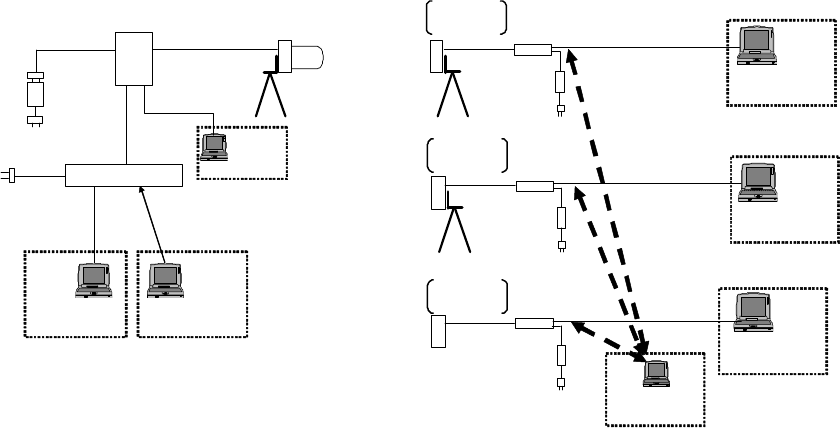
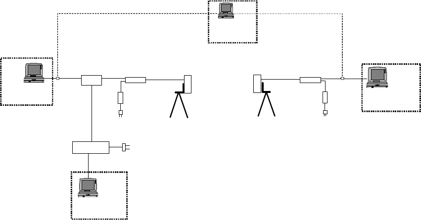
10. System example Point to Multipoint system
An example point-to-multipoint system configuration is shown in Figure 10-1.
The settings of this system configuration are as follows:
AP setting: Table 10-1
WT setting: Table 10-2
VLAN switch setting: Figure 10-2
RFU
IFU-RFU Cable
DC-48V Cable
DC-48V
Connector
L2SW
LAN Cable
LAN Cable
LAN Cable
OpS PC Test PC
LAN Cable WT Adapter
AC Adapter
LAN Cable
tripod
tripod
WT1
LAN Cable WT Adapter
AC Adapter
LAN Cable
tripod
LAN Cable WT Adapter
AC Adapter
Test PC
Test PC
IFU
Management Cable
(Serial Cable)
IP :192.168.2.100
Sub:255.255.255.0
IP :192.168.0.120
Sub:255.255.255.0
IP :192.168.0.1
Sub:255.255.255.0
IP :192.168.2.101
Sub:255.255.255.0
IP :192.168.2.102
Sub:255.255.255.0
VID:2
non-transparent
IP:192.168.1.100
WT2
AC-DC
Converter
AC100∼240V
TypeA or TypeC
AC100∼240V
TypeA or TypeC
AC100∼240V
TypeC
AC100∼240V
TypeC
AC100∼240V
TypeC
Maintenance Tool
WT2WT3
OpS
Maintenance Tool
IP :192.168.1.101
Sub:255.255.255.0
VID:50
non-transparent
IP:192.168.1.100
WT3 VID:100
non-transparent
IP:192.168.1.100
WT1
Test PC
IP :192.168.2.103
Sub:255.255.255.0
LAN Cable
only Setup
Figure 10-1 System example Point to Multipoint

10-158
Table 10-1 Setup parameters AP(Point to Multipoint)
AP
Item Value Tool
OpS Frame Priority 4 Management Tool
User Frame Priority 0 Management Tool
OpS Frame Vlan-ID 500 Management Tool
AP IP address 192.168.0.1 Management Tool
Subnet mask 255.255.255.0 Management Tool
Default gateway 192.168.0.254 Management Tool
Trap Des. IP1 192.168.0.120 Management Tool
Trap Des. IP2 non-Reg Management Tool
Trap Des. IP3 non-Reg Management Tool
Ether-IF1 Active Management Tool
Ether-IF2 non-Active Management Tool
Radio frequency Management Tool
AP ID number 1 OpS
Upstream Arbi.BW 2 OpS
AP Trans. Level 14 OpS
AP Reg. Status Reg OpS
RFU Transmission Enable OpS
Modulation Method Mixed OpS

10-159
Table 10-2 Setup parameters WT(Point to Multipoint)
WT WT1 WT2 WT3
Item Value Value Value Tool
WT ID Number 1 2 3 Management Tool
AP ID Number 1 1 1 Management Tool
Encryption
Parameter 1234567890 0987654321 9876543210 Management Tool
Select WT ID
number 1 2 3 OpS
VLAN-TAG Cont non-transparent
non-transparent non-transparent
OpS
Authen. Param 1234567890 0987654321 9876543210 OpS
Serial number
(example) NJJW000011T NJJW000012T NJJW000013T
OpS
WT Reg. Status Reg Reg Reg OpS
Modulation Method
adaptive adaptive adaptive OpS
Interface Class Auto Auto Auto OpS
RFU Transmission
Enable Enable Enable OpS
VLAN-ID 2 50 100 OpS
VLAN-ID
Registration Status
Reg Reg Reg OpS
Out of Service / In
Service In Service In Service In Service OpS
10-160
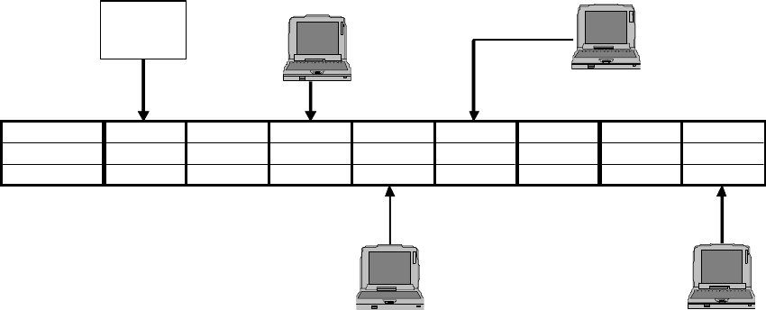
Point to Maltipoint VLAN SW parameters
PortNumber 1 2 3 4 5 6 7 8
tag type tagged untag untag untag untag untag untag untag
VID Number Default Default 2 50 100 200 300 500
OpS PC
In case of connecting
with WT1's TestPC
In case of connecting
with WT2's TestPC
AP IFU
L2 SW
In case of connecting
with WT3's TestPC
AP's TestPC
AP's TestPC
AP's TestPC
Figure 10-2 Point to Maltipoint VLAN SW parameters
11-161
11. System example Point to Point
An example point-to-point system configuration is shown in Figure 11-1.
The settings of this system configuration are as follows:
setting: Table 11-1
VLAN switch setting: Figure 11-2
L2SW
LAN Cable
OpS PC
LAN Cable
WT Adapter
AC Adapter
LAN Cable
tripod
WT1
Master
LAN Cable WT Adapter
AC Adapter
LAN Cable
tripod
Test PC
IP :192.168.1.120
Sub:255.255.255.0
IP :192.168.2.101
Sub:255.255.255.0
WT2
Slave
AC100∼240V
TypeA or TypeC
AC100∼240V
TypeC
AC100∼240V
TypeC
Test PC
IP :192.168.2.100
Sub:255.255.255.0
IP :192.168.1.101
Sub:255.255.255.0
Maintenance PC
IP :192.168.1.100
Sub:255.255.255.0 IP :192.168.1.100
Sub:255.255.255.0
LAN Cable
LAN
Cable
SW-HUB
Figure 11-1 System example Point to Point

11-162
Table 11-1 Setup parameters WT(Master) / WT(Slave) (Point to Point)
WT1 (Master) WT2 (Slave)
Item Value Value Tool
System ID number 11111 11111 Management Tool
Encryption Parameter
12345 12345 Management Tool
Sireal No. Management Tool
Trans. level 14 14 Management Tool
OpS Fra. Praiority 0 - Management Tool
OpS Fra. Vlan-ID 500 - Management Tool
IP address 192.168.1.100 - Management Tool
Subnet mask 255.255.255.0 - Management Tool
Default gateway 192.168.1.254 - Management Tool
Trap Des. IP Add.1 192.168.1.120 - Management Tool
Trap Des. IP Add.2 non-Reg - Management Tool
Trap Des. IP Add.3 non-Reg - Management Tool
Interface Class AUTO - Management Tool
Reg. Status Registered - Management Tool
RFU Transimission Enable - Management Tool /OpS
Radio frequency Management Tool
ATPC off off Management Tool
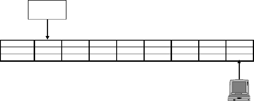
11-163
Point to Point VLAN SW parameters
PortNumber 1 2 3 4 5 6 7 8
tag type tagged untag untag untag untag untag untag untag
VID Number Default Default 2 50 100 200 300 500
OpS PC
WT1 adapter
Master
L2 SW
Figure 11-2 Point to Point VLAN SW parameters

11-164
 ̄ ̄ ̄ ̄ ̄ ̄ ̄ ̄ ̄ ̄ ̄ ̄ ̄ ̄ ̄ ̄ ̄ ̄ ̄ ̄ ̄ ̄ ̄ ̄
JRC FWA SYSTEM
Instruction Manual
H-7YZCM0101B
Rev. 3.4
24/SEP./2008
 ̄ ̄ ̄ ̄ ̄ ̄ ̄ ̄ ̄ ̄ ̄ ̄ ̄ ̄ ̄ ̄ ̄ ̄ ̄ ̄ ̄ ̄ ̄ ̄