Japan Radio NTG525-EUL Wireless Access System User Manual Instruction manual
Japan Radio Co Ltd. Wireless Access System Instruction manual
UserManual.wiki
>
Japan Radio
>
NTG525-EUL User Manual
>
Instruction manual
Contents
1.
Instruction manual
2.
Managenment ToolInstruction manual
Instruction manual
Navigation menu
Upload a User Manual
Namespaces
Wiki Guide
HTML
PDF
Info
Views
User Manual
Discussion / Help
Navigation

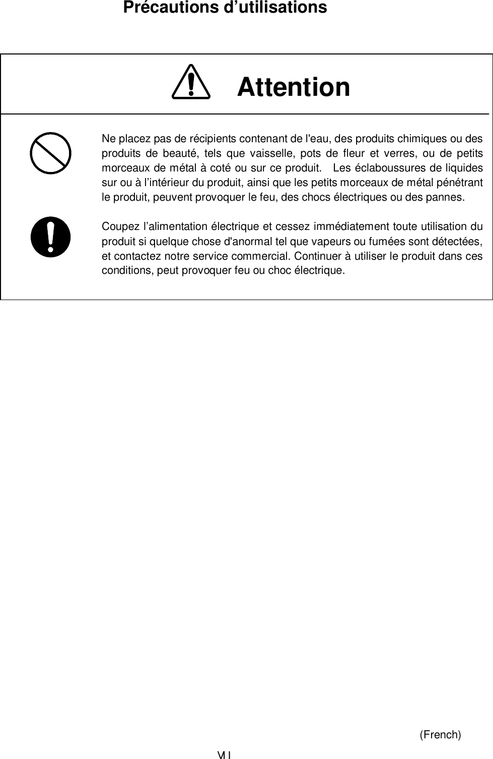
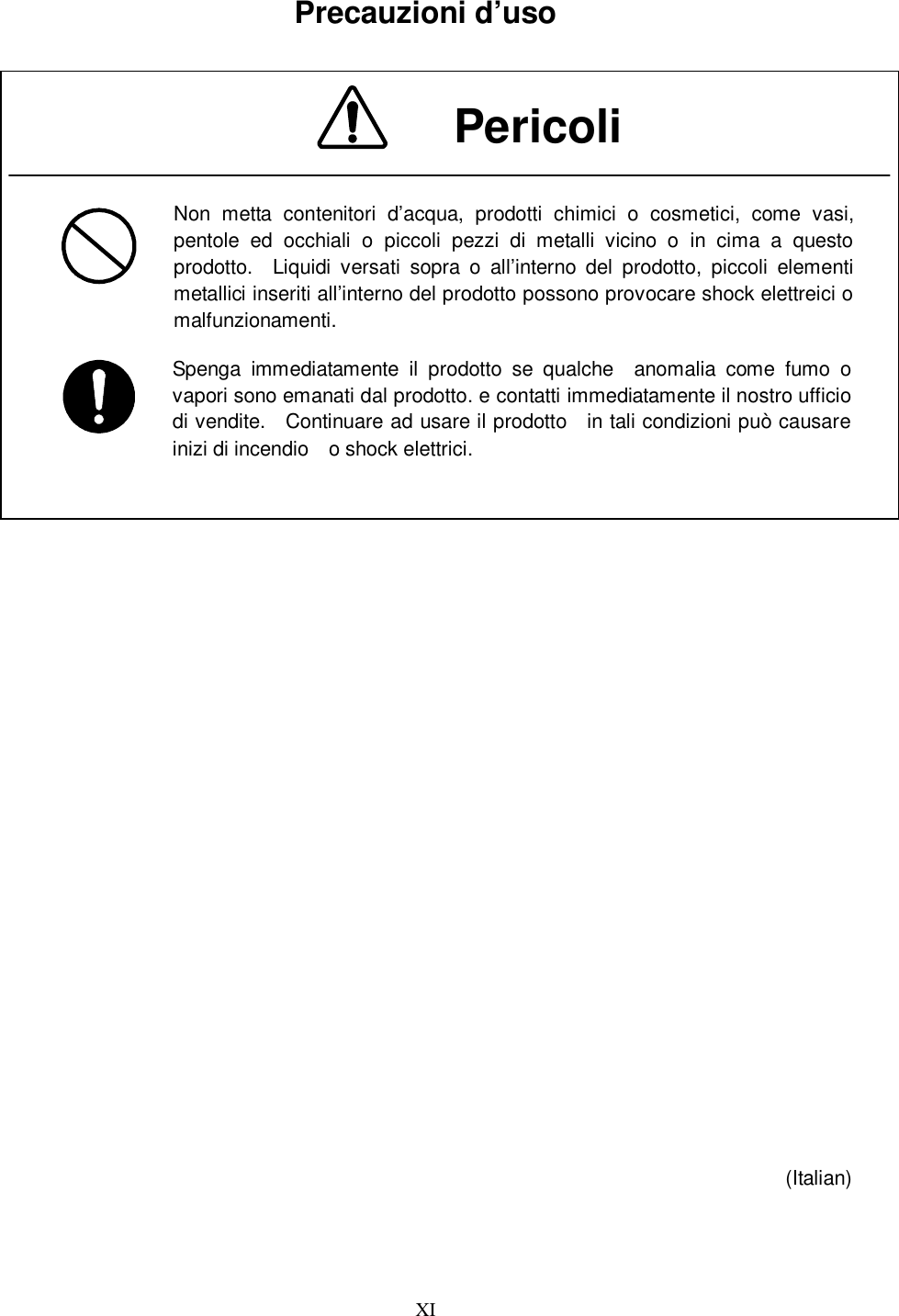
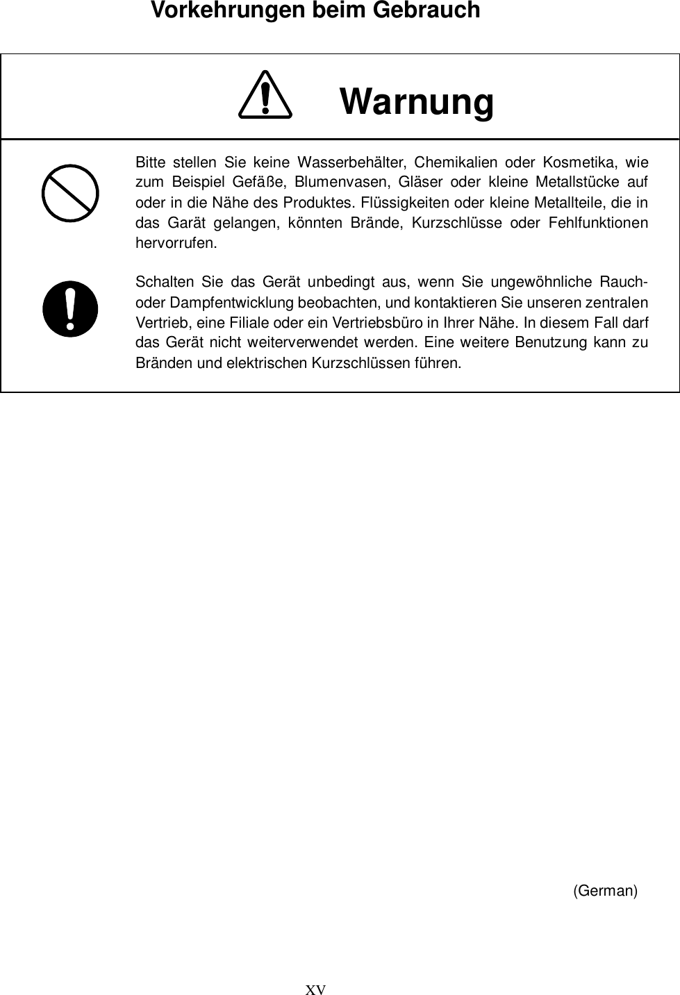


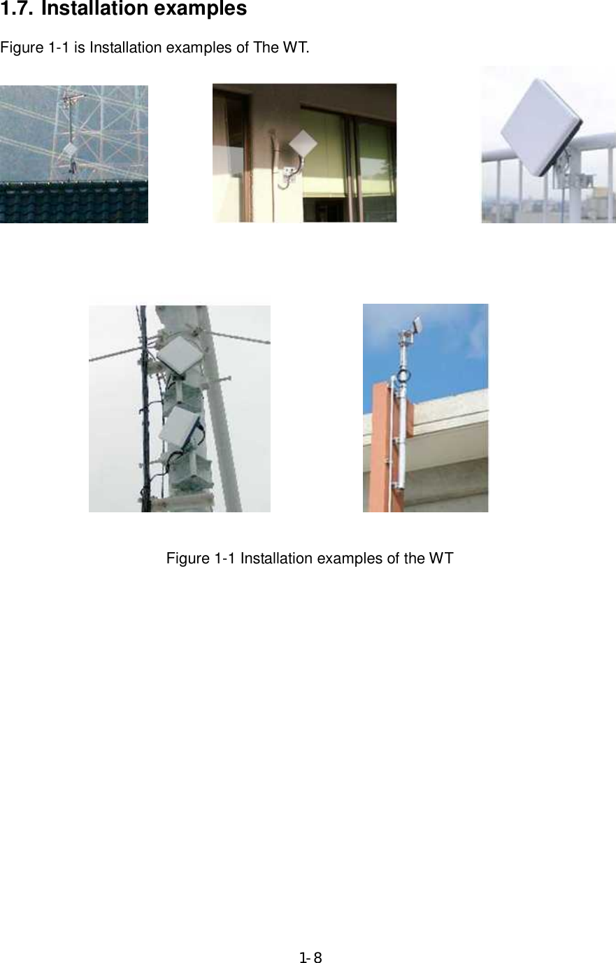
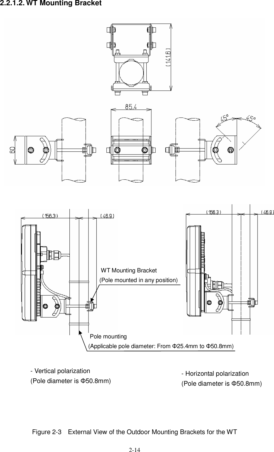
![1-9 1.8. Components Table 1-1 Components List No. Name Model Description 1 WT (Wireless Terminal) -NTG-525USL: 24.250-24.450GHz (FCC [Lch]) -NTG-525EUL: 24.549-25.445GHz (ETSI [Lch] and FCC [Hch]): -NTG-525EUH:25.557-26.453GHz (ETSI [Hch]) The WT is a radio unit that accommodates all the antenna, radio transceiver, signal processor and interface section in the same housing. It supports 100BASE-TX and 1000BASE-T user interfaces to connect a personal computer and hub. 1.1 WT mounting bracket MPBX46819 The WT mounting bracket is used to mount the WT at a pole. Including in WT 2 Antenna direction adjustment tool NKK-163 This is the antenna direction adjustment tools for the WT. 3 WIPAS2 INSTRUCTION MANUAL (CD-ROM) H-7YZCM5106 INSTRUCTION MANUAL is included in this CD-ROM 3.1 WIPAS2 INSTRUCTION MANUAL H-7YZCM5107 INSTRUCTION MANUAL Subject to change without notice. A customer prepares for PoE PSE, Ethernet Cable, and Ground wire.](https://usermanual.wiki/Japan-Radio/NTG525-EUL.Instruction-manual/User-Guide-1684776-Page-27.png)

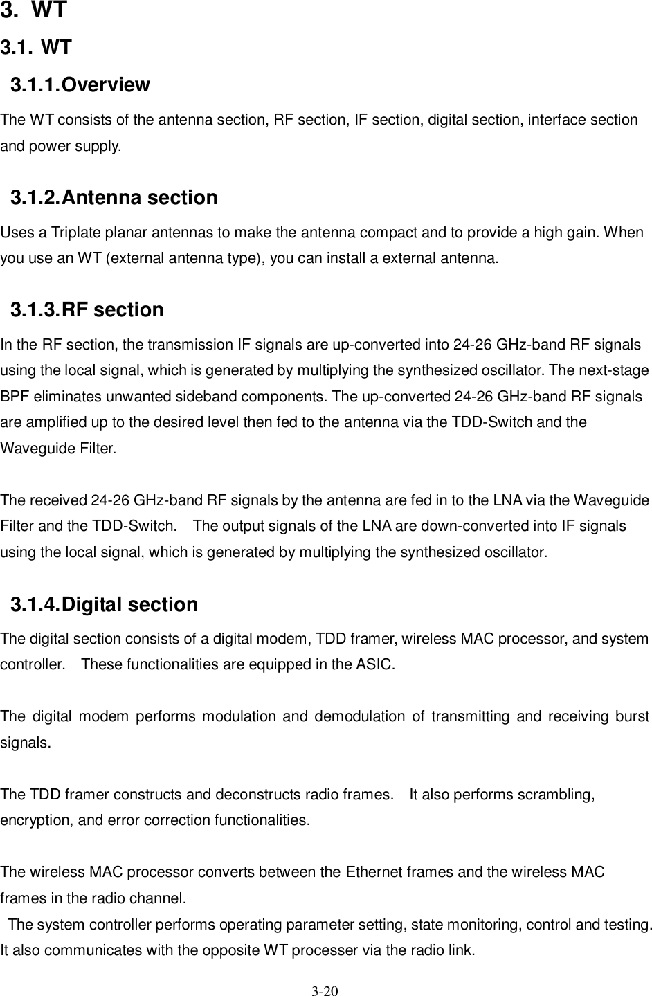
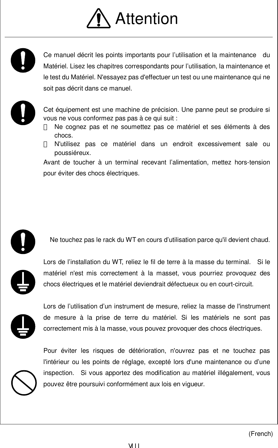
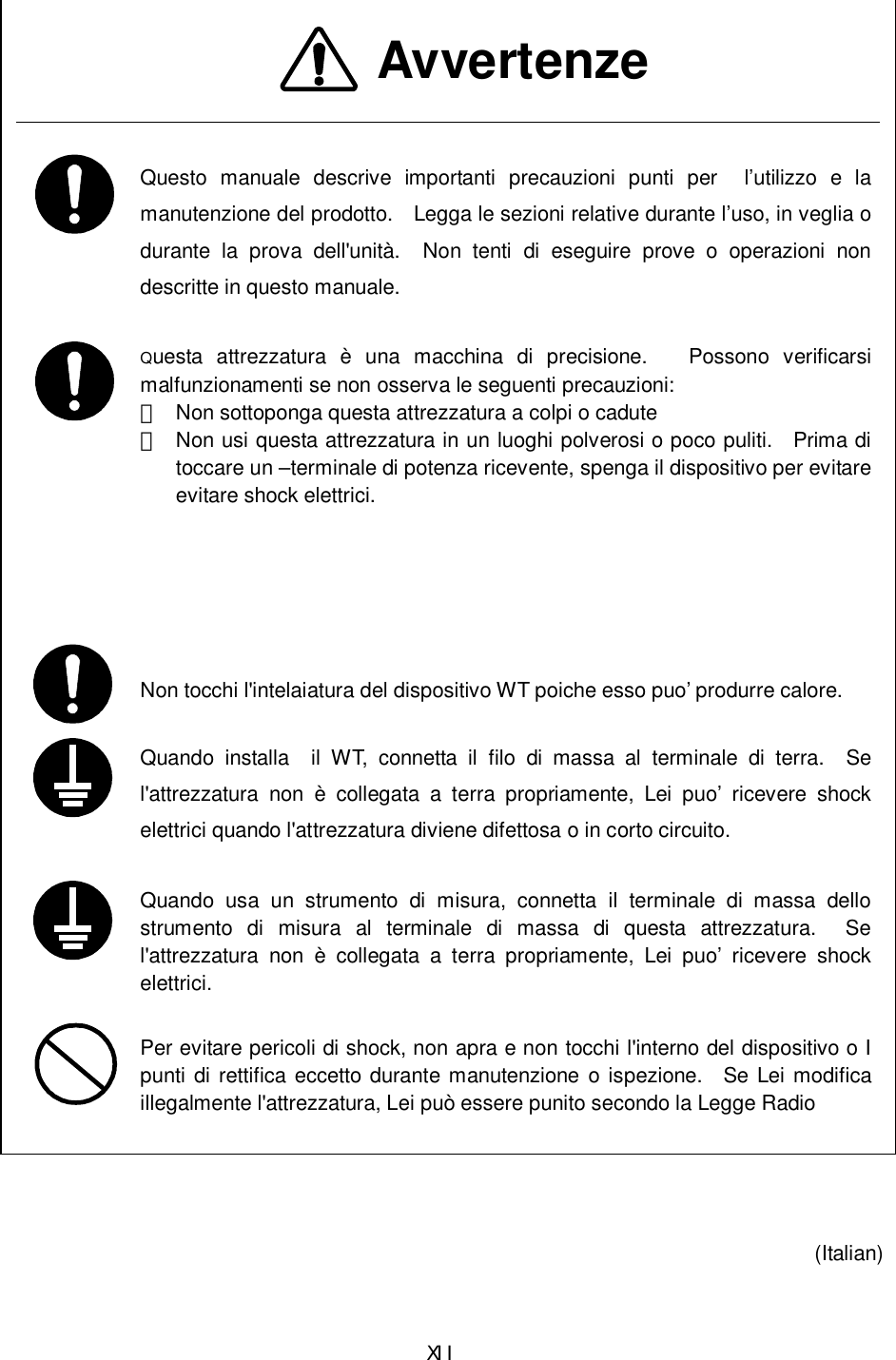
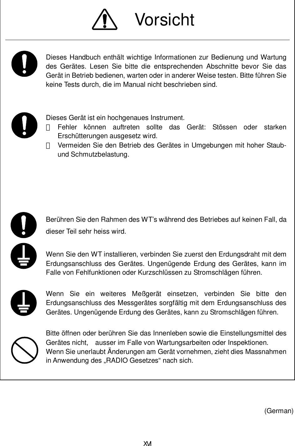
![3-21 3.1.5. Interface section The interface section provides the physical interfaces of Ethernet for user interface. It has a lightning surge protector to protect the unit against external surges. 3.1.6. Power supply The power supply section generates various voltages used within the unit from input power of PoE PSE. Figure 3-1 is a block diagram of the WT. BPFIFRJ-45 [1000BASE-T]BalunQuadratureDemodulator0/00/90POWER over EtherGigabitsEthernetTtansceiverfor1000BASE-T100BASE-TX10Base-TGigabitsEthernetMACCPUATPC1D/A ConvAGC1D/A ConvQuadraturemodulator0/00/90BalunSplitterBalunSAW_BPFLPFRS232CDrv/RecMAINTPORT25MHzSDRAM128Mbit x32FROM64MbitTempSensorATTControlDriversBalunWGBPFSYSTEMRESETPLL160/80MHzPLL125MHzSDRAMfor MAC(256Mbit)x32TDDcont250MHzHigh SpeedBaseBand SoCBBfilterIF TPCIF AGCAGC2D/A Conv40MHzBBfilter2.4GHzSynthefor IFTCXO20MHz 3.0GHzSynthefor RFx4ATTx2BalunLNAPAUP ConvDown ConvTDDControlDriversTXATTcontRXATTcontATPC2D/A ConvSPI20/40MRFRF TPCDigitalMODEMBaseBand12bitD/A ConvBaseBand10bitA/D ConvBalunATTx2RF TPCRF TPCRXLevelDC/DCConv+5V+3.3V+1.0V +5.0V - 5.0V +6.5 VDC/DCConverter DC/DCConverterPowerDC/DCConverterDC/DCConverterInterface Digital+13VDC/DCConverter Figure 3-1 WT Block Diagra](https://usermanual.wiki/Japan-Radio/NTG525-EUL.Instruction-manual/User-Guide-1684776-Page-39.png)

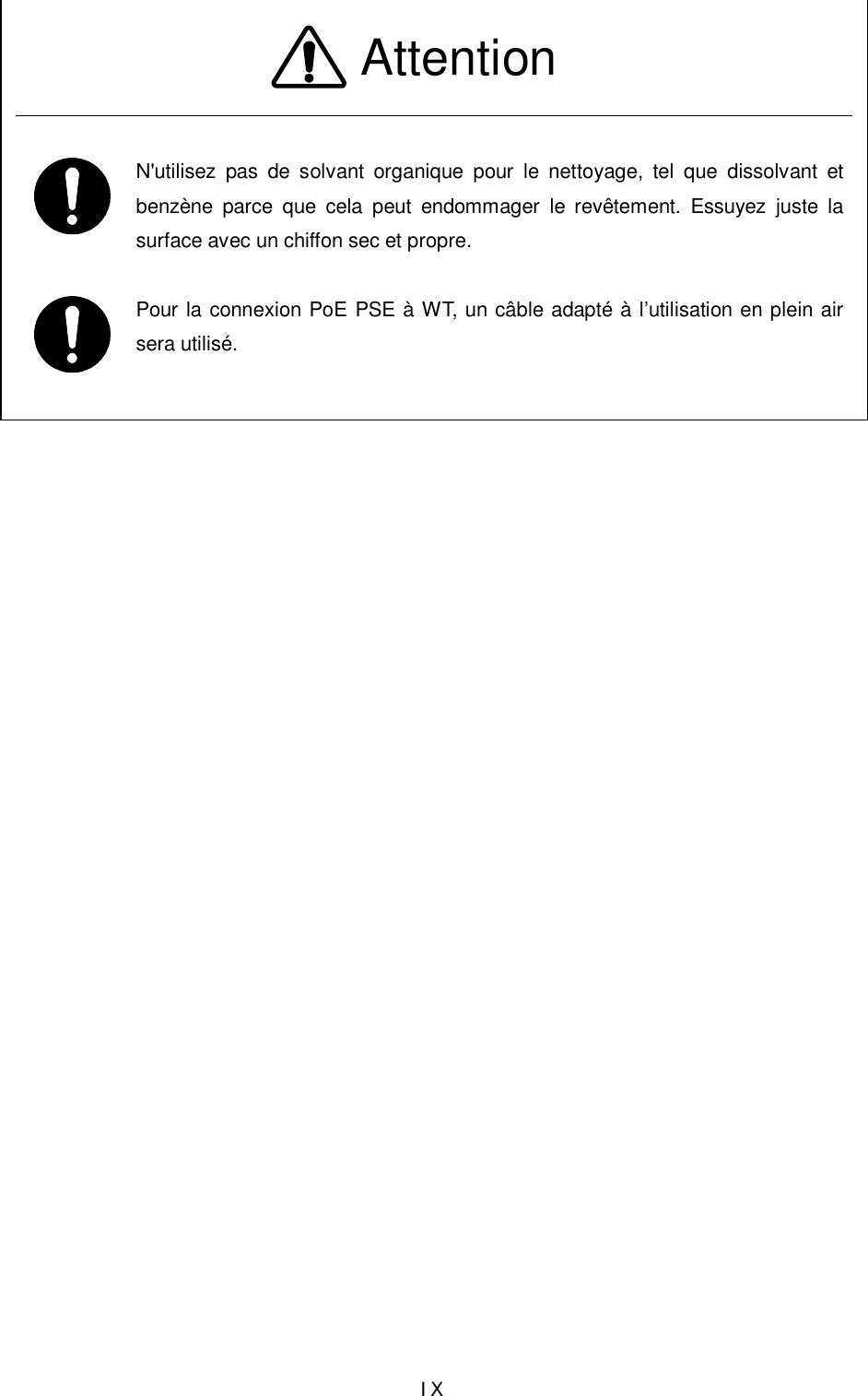
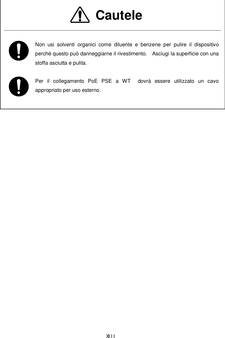
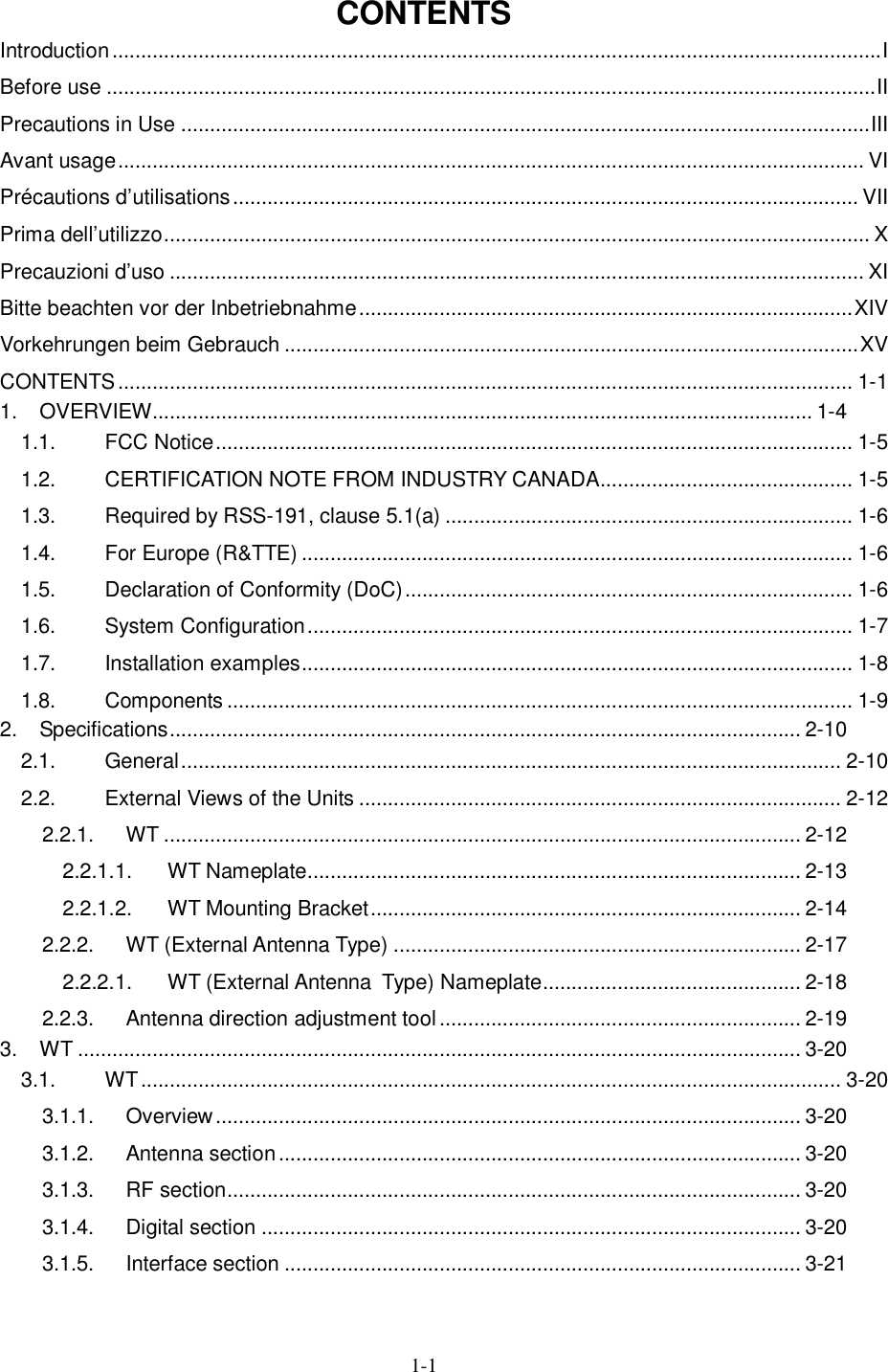
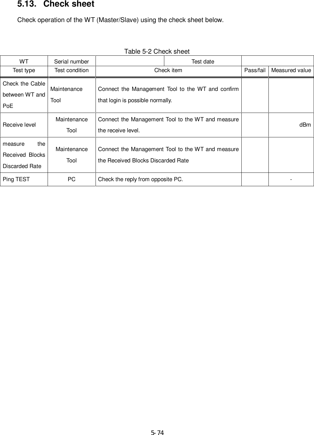
![5-57 5.7.2. The receive level and the distance In a point-to-point system, the receiving level at clear sky and the distance are related as shown as bellows Receiving Level vs Distance(SymbolRate:40MHz,QPSK)ATPC ON ATPC OFFMaximumreceiving levelMinimum receivinglevel(QPSK)-90.0-80.0-70.0-60.0-50.0-40.0-30.0-20.0-10.00.010.01 10 100 1000 10000Distance [m]Receiving Level [dBm] Figure 5-43 Receiving Level and Distance (SymbolRate:40MHz,QPSK) Receiving level](https://usermanual.wiki/Japan-Radio/NTG525-EUL.Instruction-manual/User-Guide-1684776-Page-75.png)
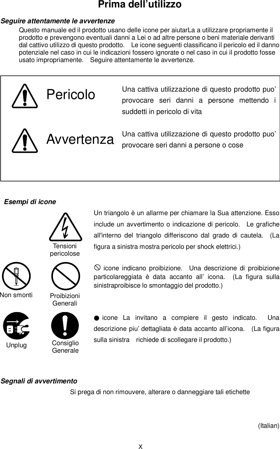
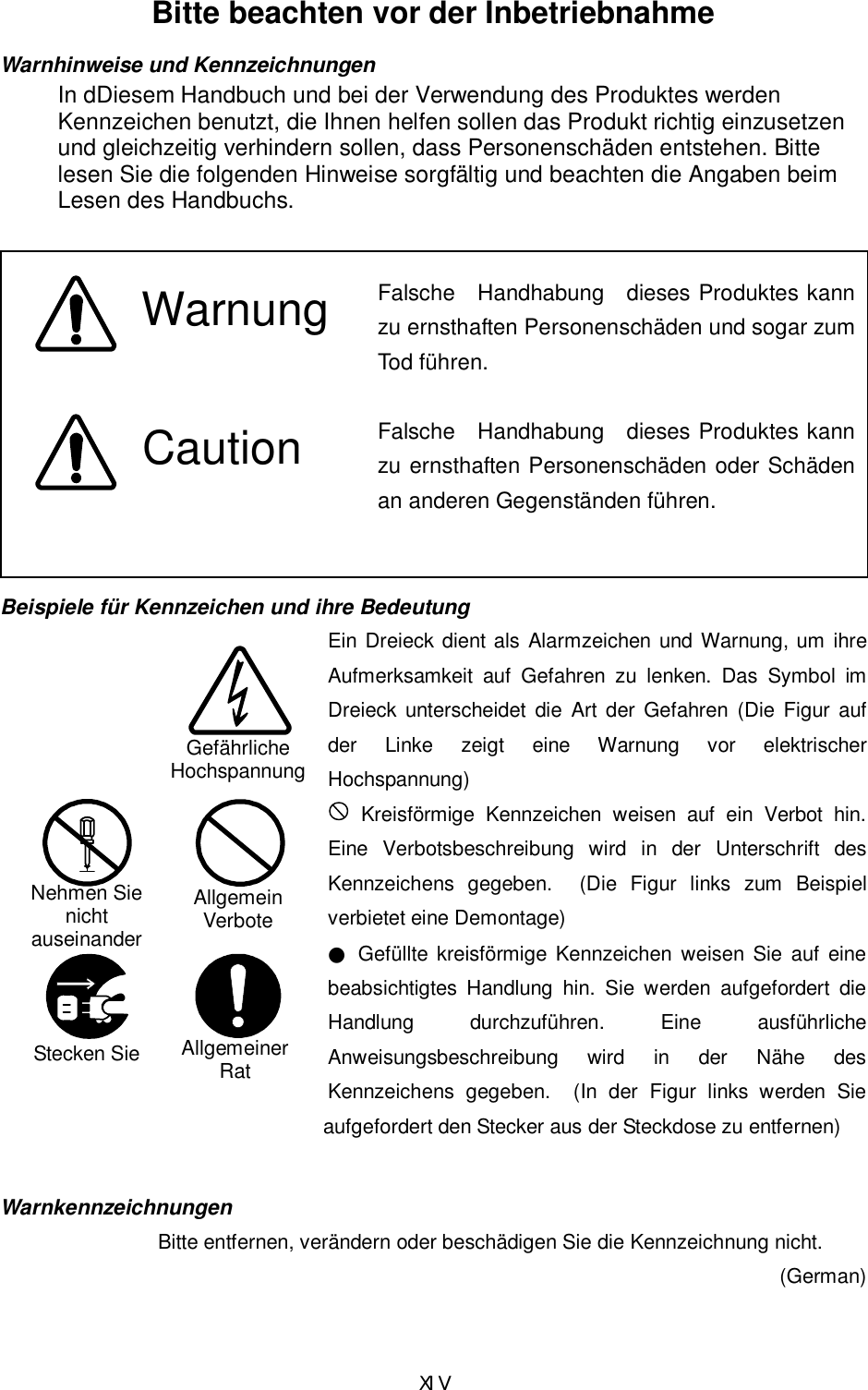
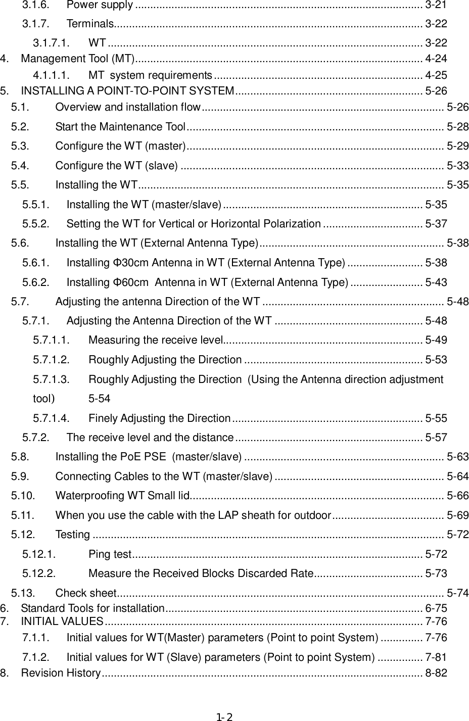
![5-58 Receiving Level vs Distance(SymbolRate:40MHz,16QAM)ATPC ON ATPC OFFMaximumreceiving levelMinimum receivinglevel(16QAM)-90.0-80.0-70.0-60.0-50.0-40.0-30.0-20.0-10.00.010.01 10 100 1000 10000Distance [m]Receiving Level [dBm] Figure 5-44 Receiving Level and Distance (SymbolRate:40MHz,16QAM)](https://usermanual.wiki/Japan-Radio/NTG525-EUL.Instruction-manual/User-Guide-1684776-Page-76.png)
![5-59 Receiving Level vs Distance(SymbolRate:40MHz,64QAM)ATPC ON ATPC OFFMaximumreceiving levelMinimum receivinglevel(64QAM)-90.0-80.0-70.0-60.0-50.0-40.0-30.0-20.0-10.00.010.01 10 100 1000 10000Distance [m]Receiving Level [dBm] Figure 5-45 Receiving Level and Distance (SymbolRate:40MHz,64QAM)](https://usermanual.wiki/Japan-Radio/NTG525-EUL.Instruction-manual/User-Guide-1684776-Page-77.png)
![5-60 Receiving Level vs Distance(SymbolRate:20MHz,QPSK)ATPC ON ATPC OFFMaximumreceiving levelMinimum receivinglevel(QPSK)-90.0-80.0-70.0-60.0-50.0-40.0-30.0-20.0-10.00.010.01 10 100 1000 10000Distance [m]Receiving Level [dBm] Figure 5-46 Receiving Level and Distance (SymbolRate:20MHz,QPSK)](https://usermanual.wiki/Japan-Radio/NTG525-EUL.Instruction-manual/User-Guide-1684776-Page-78.png)
![5-61 Receiving Level vs Distance(SymbolRate:20MHz,16QAM)ATPC ON ATPC OFFMaximumreceiving levelMinimum receivinglevel(16QAM)-90.0-80.0-70.0-60.0-50.0-40.0-30.0-20.0-10.00.010.01 10 100 1000 10000Distance [m]Receiving Level [dBm] Figure 5-47 Receiving Level and Distance (SymbolRate:20MHz,16QAM)](https://usermanual.wiki/Japan-Radio/NTG525-EUL.Instruction-manual/User-Guide-1684776-Page-79.png)
![5-62 Receiving Level vs Distance(SymbolRate:20MHz,64QAM)ATPC ON ATPC OFFMaximumreceiving levelMinimum receivinglevel(64QAM)-90.0-80.0-70.0-60.0-50.0-40.0-30.0-20.0-10.00.010.01 10 100 1000 10000Distance [m]Receiving Level [dBm] Figure 5-48 Receiving Level and Distance (SymbolRate:20MHz,64QAM)](https://usermanual.wiki/Japan-Radio/NTG525-EUL.Instruction-manual/User-Guide-1684776-Page-80.png)
![6-75 6. Standard Tools for installation The table below lists the tools used during installation or maintenance of the units. Table 6-1 Tools Used No. Unit name Used for: Tightening torque [N•cm] Tool 1 Small lid M4 127 Torx driver (VESSEL T20H-120) 2 Mounting bracket M6 850 Allen wrench (Width across flats: 5) 3 FG Terminal M6 850 #2 phillips screwdriver 4 WT Ethernet cable Crimping tool for RJ-45 (Release-after-crimp type) The appropriate tightening torque is 10% of the value indicated in the table.](https://usermanual.wiki/Japan-Radio/NTG525-EUL.Instruction-manual/User-Guide-1684776-Page-93.png)
![7-76 7. INITIAL VALUES 7.1.1. Initial values for WT(Master) parameters (Point to point System) Table 7-1 lists the WT defaults set in the factory. No. Parameters 1 Parameters 2 Initial values QoS and Traffic Control 12 Class 7 1000 [KB] 13 Class 6 1000 [KB] 14 Class 5 1000 [KB] 15 Class 4 1000 [KB] 16 Class 3 1000 [KB] 17 Class 2 1000 [KB] 18 Class 1 1000 [KB] 19 Buffer Size Configuration(Master) Class 0 1000 [KB] 20 Class 7 1000 [KB] 21 Class 6 1000 [KB] 22 Class 5 1000 [KB] 23 Class 4 1000 [KB] 24 Class 3 1000 [KB] 25 Class 2 1000 [KB] 26 Class 1 1000 [KB] 27 Buffer Size Configuration(Slave) Class 0 1000 [KB] 28 COS assignment for Management Communication from Master to Slave 7 29 Class 7 In Service 30 Class 6 In Service 31 Class 5 In Service 32 Class 4 In Service 33 Class 3 In Service 34 Class 2 In Service 35 Class 1 In Service 36 QoS Priority Class Configuration(Master) Class 0 In Service](https://usermanual.wiki/Japan-Radio/NTG525-EUL.Instruction-manual/User-Guide-1684776-Page-94.png)
![7-77 No. Parameters 1 Parameters 2 Initial values 37 Class 7 In Service 38 Class 6 In Service 39 Class 5 In Service 40 Class 4 In Service 41 Class 3 In Service 42 Class 2 In Service 43 Class 1 In Service 44 QoS Priority Class Configuration(Slave) Class 0 In Service 45 Dynamic TDD Fixed 46 DL /UL Ratio DL Ratio 50 [%] 47 COS 値7 7 48 COS 値6 0 49 COS 値5 0 50 COS 値4 0 51 COS 値3 0 52 COS 値2 0 53 COS 値1 0 54 COS [0-7] vs. Priority Class [0-7]("7"is the highest Priority) Table COS 値0 0 55 IP Precedense 56 Master TOS vs. COS [0-7] Table 7∼0 0 57 DSCP 58 Master TC [0-255] vs. COS [0-7] Table 63∼0 0 59 except following EtherTypes 0 60 Master EtherType vs. COS [0-7] Table 15 setting items Not set 61 IP Precedense 62 Slave Slave TOS vs. COS [0-7] Table 7∼0 0 63 DSCP 64 Slave TC [0-255] vs. COS [0-7] Table 63∼0 0 65 except following EtherTypes 0 66 Slave EtherType vs. COS [0-7] Table 15 setting items Not set 67 Class7∼0(QPSK) 68 Class7∼0(16QAM) 69 Policing Rate(Master) Class7∼0(64QAM) 0[Mbps] 70 Class7∼0(QPSK) 71 Class7∼0(16QAM) 72 Policing Rate(Slave) Class7∼0(64QAM) 0[Mbps]](https://usermanual.wiki/Japan-Radio/NTG525-EUL.Instruction-manual/User-Guide-1684776-Page-95.png)
![7-78 No. Parameters 1 Parameters 2 Initial values 73 Class7∼0(QPSK) 74 Class7∼0(16QAM) 75 Shaping Rate(Master) Class7∼0(64QAM) 0[Mbps] 76 Class7∼0(QPSK) 77 Class7∼0(16QAM) 78 Shaping Rate(Slave) Class7∼0(64QAM) 0[Mbps] Configuration (Radio) 79 Operating Mode P-P(Master) 80 Symbol Rate 40.0 [MHz] 81 Frame ID Number 1 82 Encryption Parameter 1234567890 83 Maximum Service Distance 7 [km] 84 MTPC Transmitted Level 5.0 [dBm] 85 ATPC Enable 86 ATPC 87 Network Element Name Not set 88 Scanning CH Range 4∼42[CH] 89 90 Modulation 91 DL Modulation Scheme 64QAM 92 Modulation UL Modulation Scheme 64QAM 93 Master Enable 94 RF Transmission Slave Enable Configuration (Network) 95 IPaddress 192.168.1.100 96 Subnet mask 255.255.255.0 97 IPv4 Default gateway Not set 98 Disable 99 IPaddress Not set 100 IPv6 Default gateway Not set 101 Ethernet configuration 1000BASE-T(AUTO) 102 Disable 103 VID 0 104 Management VLAN TAG(No.1) COS 0 105 Disable 106 VID 0 107 Management VLAN TAG(No.2) COS 0 108 Disable 109 VID 0 110 Management VLAN TAG(No.3) COS 0 111 Disable 121 <SNMP> OpS1 IPv4 0.0.0.0](https://usermanual.wiki/Japan-Radio/NTG525-EUL.Instruction-manual/User-Guide-1684776-Page-96.png)

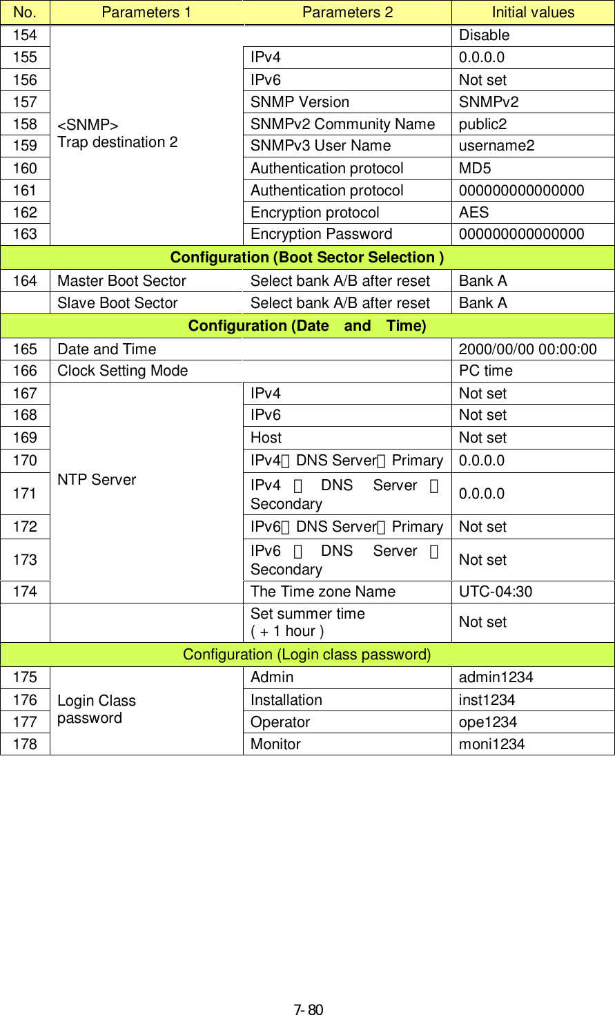
![7-817.1.2. Initial values for WT (Slave) parameters (Point to point System) Table 7-2 lists the WT (Slave) defaults set in the factory. No. Parameters 1 Parameters 2 Initial values Traffic Control 12 COS assignment for Management Communication from Master to Slave 7 Configuration (Radio) 20 Operating Mode P-P(Master) 21 Symbol Rate 40.0 [MHz] 22 Frame ID Number 1 23 Encryption Parameter 1234567890 24 MTPC MTPC Transmitted Level 5.0 [dBm] 25 Network Element Name Not set Configuration (Network) 27 IPaddress 192.168.1.100 28 Subnet mask 255.255.255.0 29 IPv4 Default gateway Not set 30 Disable 31 IPaddress Not set 32 IPv6 Default gateway Not set 33 Ethernet configuration 1000BASE-T(AUTO) 34 Disable 35 VID 0 36 Management VLAN TAG(No.1) COS 0 37 Disable 38 VID 0 39 Management VLAN TAG(No.2) COS 0 40 Disable 41 VID 0 42 Management VLAN TAG(No.3) COS 0 Configuration (Login class password) 45 Admin admin1234 46 Installation inst1234 47 Operator ope1234 48 Login Class password Monitor moni1234](https://usermanual.wiki/Japan-Radio/NTG525-EUL.Instruction-manual/User-Guide-1684776-Page-99.png)