Japan Radio NTG525-EUL Wireless Access System User Manual Instruction manual
Japan Radio Co Ltd. Wireless Access System Instruction manual
Contents
- 1. Instruction manual
- 2. Managenment ToolInstruction manual
Instruction manual

0
WIPAS2
INSTRUCTION MANUAL
(Point to Point)
Rev. 1.3
20/Apr./2012
I
Introduction
Read this instruction manual carefully before use. Be sure you fully understand the
instructions in this manual before using the equipment.
After reading, save this instruction manual and refer to it as necessary. If you have any
questions about or there is something wrong with the equipment, refer to this manual.
II
Before use
Warning Indications
This manual and the product use some icons to help you use the product properly and
prevent any damage to you and other people or property. The following icons classify the
potential damage if the indications are ignored or the product is used improperly. When
reading the manual, keep these in mind.
Examples of icons
A triangle is an alert to call your attention including a warning
or danger indication. The graphics within the triangle differs
depending on the caution. (The figure on the left shows a
caution for electrical shocks.)
icons indicate prohibition. A detailed prohibition description
is given in the vicinity of the icon. (The figure on the left
prohibits disassembly.)
icons require you to perform the item. A detailed
instruction is given in the vicinity of the icon. (The figure on the
left instruct to unplug the equipment.)
Warning labels
Do not remove, damage or alter the warning labels.
Warning
Caution
Wrong handling of this product may cause
serious personal injury or death.
Wrong handling of this product may cause
personal injury or damage to properties.
Dangerous
voltages
General
prohibitions
General
advice
Do not
disassemble
Unplug

III
Precautions in Use
Warning
Don’t place containers having water, chemicals or cosmetics, such as
vessels, flower pots and glasses, or small pieces of metals near or on top
of this product. Liquids spilled over or into or small metal pieces getting
into the product may cause fire, electrical shocks or failures.
Turn off the power and stop using the unit immediately if something
abnormal such as fumes or smoke is detected, and contact our sales
department, branch or sales office. Continuing to use the product as is
may cause fire or electrical shock.
IV
Cautions
This manual describes important points to operate and maintain the
equipment. Read the related sections when operating, maintaining
and testing the unit. Do not try to carry out a test or maintenance not
covered in this manual.
This equipment is a precision machine. A failure may occur if you do
not observe the following:
・ Do not jar or subject this equipment and the units to shocks.
・ Do not use this equipment in a place with excessive dirt or dust.
Before touching a power-receiving terminal, turn the input power off to
avoid electrical shocks.
Do not touch the rack of the WT duirng operation because it becomes
hot.
When installing the WT, connect the ground wire to the ground
terminal. If the equipment is not grounded properly, you may get
electrical shocks when the equipment becomes faulty or shorted.
When using a measuring instrument, connect the ground terminal of
the measuring instrument to the ground terminal of this equipment. If
the equipment is not grounded properly, you may get electrical
shocks.
To avoid shock hazards, do not open and touch the inside or
adjustment points except for maintenance or inspection. If you modify
the equipment illegally, you may be punished according to the Radio
Law.

V
Cautions
Don’t use organic solvent for cleaning such as thinner and benzene because
this may damage the coating. Just wipe the surface with a clean dry cloth.
For the connection PoE PSE to WT and a cable suitable for outdoor use shall
be installed.
VI
Avant usage
Indications Préventives
This manual and the product use some icons to help you use the product
properly and prevent any damage to you and other people or property. The
following icons classify the potential damage if the indications are ignored or the
product is used improperly. When reading the manual, keep these in mind.
Exemples d'icônes
Un triangle est une alerte pour attirer votre attention en cas de
danger ou de conseil de prudence. Le signe à l’interieur du
triangle diffère selon le risque. (L’exemple de gauche signale
un risque électrique.)
Les deux icônes de gauche indiquent une interdiction. Une
description plus détaillée est donnée près de l'icône (la plus à
gauche interdit le démontage.)
Ce type d’icône exige que vous exécutiez l'action Une
description plus détaillée est donnée près de l'icône (la plus à
gauche exige de debrancher le matériel avant toute opération.)
Attention
N'enlevez jamais, n’endommagez jamais et ne changez jamais les signalisation de
danger.
(French)
Danger
Prudence
Une mauvaise utilisation de ce produit peut
causer de sérieux dommages corporels ou la
mort.
Une mauvaise utilisation de ce produit peut
causer des dommages corporels ou
endommager des biens.
Le manuel d’utilisation et le produit utilisent des icônes pour vous aider à utiliser correctement le
produit et prévenir tout dommages sur vous, sur des tiers ou sur des biens. Les icônes qui suivent,
indiquent le niveau des dommages éventuels si les précautions indiquées sont ignorées ou si le
produit est mal utilisé. Quand vous lirez le manuel d’utilisation, faites attention à ces indications.
Danger
électrique
Débranchez
Ne pas
démonter
Interdiction
générale
Conseil
général

VII
Précautions d’utilisations
(French)
Ne placez pas de récipients contenant de l'eau, des produits chimiques ou des
produits de beauté, tels que vaisselle, pots de fleur et verres, ou de petits
morceaux de métal à coté ou sur ce produit. Les éclaboussures de liquides
sur ou à l’intérieur du produit, ainsi que les petits morceaux de métal pénétrant
le produit, peuvent provoquer le feu, des chocs électriques ou des pannes.
Coupez l’alimentation électrique et cessez immédiatement toute utilisation du
produit si quelque chose d'anormal tel que vapeurs ou fumées sont détectées,
et contactez notre service commercial. Continuer à utiliser le produit dans ces
conditions, peut provoquer feu ou choc électrique.
Attention

VIII
(French)
Attention
Ce manuel décrit les points importants pour l’utilisation et la maintenance du
Matériel. Lisez les chapitres correspondants pour l’utilisation, la maintenance et
le test du Matériel. N'essayez pas d'effectuer un test ou une maintenance qui ne
soit pas décrit dans ce manuel.
Cet équipement est une machine de précision. Une panne peut se produire si
vous ne vous conformez pas pas à ce qui suit :
・ Ne cognez pas et ne soumettez pas ce matériel et ses éléments à des
chocs.
・ N'utilisez pas ce matériel dans un endroit excessivement sale ou
poussiéreux.
Avant de toucher à un terminal recevant l’alimentation, mettez hors-tension
pour éviter des chocs électriques.
Ne touchez pas le rack du WT en cours d’utilisation parce qu'il devient chaud.
Lors de l’installation du WT, reliez le fil de terre à la masse du terminal. Si le
matériel n'est mis correctement à la masset, vous pourriez provoquez des
chocs électriques et le matériel deviendrait défectueux ou en court-circuit.
Lors de l’utilisation d’un instrument de mesure, reliez la masse de l'instrument
de mesure à la prise de terre du matériel. Si les matériels ne sont pas
correctement mis à la masse, vous pouvez provoquer des chocs électriques.
Pour éviter les risques de détérioration, n'ouvrez pas et ne touchez pas
l'intérieur ou les points de réglage, excepté lors d'une maintenance ou d’une
inspection. Si vous apportez des modification au matériel illégalement, vous
pouvez être poursuivi conformément aux lois en vigueur.

IX
Attention
N'utilisez pas de solvant organique pour le nettoyage, tel que dissolvant et
benzène parce que cela peut endommager le revêtement. Essuyez juste la
surface avec un chiffon sec et propre.
Pour la connexion PoE PSE à WT, un câble adapté à l’utilisation en plein air
sera utilisé.
X
Prima dell’utilizzo
Seguire attentamente le avvertenze
Questo manuale ed il prodotto usano delle icone per aiutarLa a utilizzare propriamente il
prodotto e prevengono eventuali danni a Lei o ad altre persone o beni materiale derivanti
dal cattivo utilizzo di questo prodotto. Le icone seguenti classificano il pericolo ed il danno
potenziale nel caso in cui le indicazioni fossero ignorate o nel caso in cui il prodotto fosse
usato impropriamente. Seguire attentamente le avvertenze.
Esempi di icone
Un triangolo è un allarme per chiamare la Sua attenzione. Esso
include un avvertimento o indicazione di pericolo. Le grafiche
all'interno del triangolo differiscono dal grado di cautela. (La
figura a sinistra mostra pericolo per shock elettrici.)
icone indicano proibizione. Una descrizione di proibizione
particolareggiata è data accanto all’ icona. (La figura sulla
sinistraproibisce lo smontaggio del prodotto.)
●icone La invitano a compiere il gesto indicato. Una
descrizione piu’ dettagliata è data accanto all’icona. (La figura
sulla sinistra richiede di scollegare il prodotto.)
Segnali di avvertimento
Si prega di non rimouvere, alterare o danneggiare tali etichette
(Italian)
Pericolo
Avvertenza
Una cattiva utilizzazione di questo prodotto puo’
provocare seri danni a persone mettendo i
suddetti in pericolo di vita
Una cattiva utilizzazione di questo prodotto puo’
provocare seri danni a persone o cose
Tensioni
pericolose
Proibizioni
Generali
Consiglio
Generale
Non smonti
Unplug

XI
Precauzioni d’uso
(Italian)
Spenga immediatamente il prodotto se qualche anomalia come fumo o
vapori sono emanati dal prodotto. e contatti immediatamente il nostro ufficio
di vendite. Continuare ad usare il prodotto in tali condizioni può causare
inizi di incendio o shock elettrici.
Non metta contenitori d’acqua, prodotti chimici o cosmetici, come vasi,
pentole ed occhiali o piccoli pezzi di metalli vicino o in cima a questo
prodotto. Liquidi versati sopra o all’interno del prodotto, piccoli elementi
metallici inseriti all’interno del prodotto possono provocare shock elettreici o
malfunzionamenti.
Pericoli
XII
(Italian)
Avvertenze
Questo manuale descrive importanti precauzioni punti per l’utilizzo e la
manutenzione del prodotto. Legga le sezioni relative durante l’uso, in veglia o
durante la prova dell'unità.
Non tenti di eseguire prove o operazioni non
descritte in questo manuale.
Questa attrezzatura è una macchina di precisione. Possono verificarsi
malfunzionamenti se non osserva le seguenti precauzioni:
・ Non sottoponga questa attrezzatura a colpi o cadute
・ Non usi questa attrezzatura in un luoghi polverosi o poco puliti. Prima di
toccare un –terminale di potenza ricevente, spenga il dispositivo per evitare
evitare shock elettrici.
Non tocchi l'intelaiatura del dispositivo WT poiche esso puo’ produrre calore.
Quando installa il WT, connetta il filo di massa al terminale di terra. Se
l'attrezzatura non è collegata a terra propriamente, Lei puo’ ricevere shock
elettrici quando l'attrezzatura diviene difettosa o in corto circuito.
Quando usa un strumento di misura, connetta il terminale di massa dello
strumento di misura al terminale di massa di questa attrezzatura. Se
l'attrezzatura non è collegata a terra propriamente, Lei puo’ ricevere shock
elettrici.
Per evitare pericoli di shock, non apra e non tocchi l'interno del dispositivo o I
punti di rettifica eccetto durante manutenzione o ispezione. Se Lei modifica
illegalmente l'attrezzatura, Lei può essere punito secondo la Legge Radio

XIII
Cautele
Non usi solventi organici come diluente e benzene per pulire il dispositivo
perché questo può danneggiarne il rivestimento. Asciugi la superficie con una
stoffa asciutta e pulita.
Per il collegamento PoE PSE a WT dovrà essere utilizzato un cavo
appropriato per uso esterno.
XIV
Bitte beachten vor der Inbetriebnahme
Warnhinweise und Kennzeichnungen
In dDiesem Handbuch und bei der Verwendung des Produktes werden
Kennzeichen benutzt, die Ihnen helfen sollen das Produkt richtig einzusetzen
und gleichzeitig verhindern sollen, dass Personenschäden entstehen. Bitte
lesen Sie die folgenden Hinweise sorgfältig und beachten die Angaben beim
Lesen des Handbuchs.
Beispiele für Kennzeichen und ihre Bedeutung
Ein Dreieck dient als Alarmzeichen und Warnung, um ihre
Aufmerksamkeit auf Gefahren zu lenken. Das Symbol im
Dreieck unterscheidet die Art der Gefahren (Die Figur auf
der Linke zeigt eine Warnung vor elektrischer
Hochspannung)
Kreisförmige Kennzeichen weisen auf ein Verbot hin.
Eine Verbotsbeschreibung wird in der Unterschrift des
Kennzeichens gegeben. (Die Figur links zum Beispiel
verbietet eine Demontage)
● Gefüllte kreisförmige Kennzeichen weisen Sie auf eine
beabsichtigtes Handlung hin. Sie werden aufgefordert die
Handlung durchzuführen. Eine ausführliche
Anweisungsbeschreibung wird in der Nähe des
Kennzeichens gegeben. (In der Figur links werden Sie
aufgefordert den Stecker aus der Steckdose zu entfernen)
Warnkennzeichnungen
Bitte entfernen, verändern oder beschädigen Sie die Kennzeichnung nicht.
(German)
Warnung
Caution
Falsche Handhabung dieses Produktes kann
zu ernsthaften Personenschäden und sogar zum
Tod führen.
Falsche Handhabung dieses Produktes kann
zu ernsthaften Personenschäden oder Schäden
an anderen Gegenständen führen.
Gefährliche
Hochspannung
Stecken Sie
aus
Nehmen Sie
nicht
auseinander
Allgemein
Verbote
Allgemeiner
Rat

XV
Vorkehrungen beim Gebrauch
(German)
Schalten Sie das Gerät unbedingt aus, wenn Sie ungewöhnliche Rauch-
oder Dampfentwicklung beobachten, und kontaktieren Sie unseren zentralen
Vertrieb, eine Filiale oder ein Vertriebsbüro in Ihrer Nähe. In diesem Fall darf
das Gerät nicht weiterverwendet werden. Eine weitere Benutzung kann zu
Bränden und elektrischen Kurzschlüssen führen.
Bitte stellen Sie keine Wasserbehälter, Chemikalien oder Kosmetika, wie
zum Beispiel Gefäße, Blumenvasen, Gläser oder kleine Metallstücke auf
oder in die Nähe des Produktes. Flüssigkeiten oder kleine Metallteile, die in
das Garät gelangen, könnten Brände, Kurzschlüsse oder Fehlfunktionen
hervorrufen.
Warnung

XVI
(German)
Vorsicht
Dieses Handbuch enthält wichtige Informationen zur Bedienung und Wartung
des Gerätes. Lesen Sie bitte die entsprechenden Abschnitte bevor Sie das
Gerät in Betrieb bedienen, warten oder in anderer Weise testen. Bitte führen Sie
keine Tests durch, die im Manual nicht beschrieben sind.
Dieses Gerät ist ein hochgenaues Instrument.
・ Fehler können auftreten sollte das Gerät: Stössen oder starken
Erschütterungen ausgesetz wird.
・ Vermeiden Sie den Betrieb des Gerätes in Umgebungen mit hoher Staub-
und Schmutzbelastung.
Berühren Sie den Rahmen des WT’s während des Betriebes auf keinen Fall, da
dieser Teil sehr heiss wird.
Wenn Sie den WT installieren, verbinden Sie zuerst den Erdungsdraht mit dem
Erdungsanschluss des Gerätes. Ungenügende Erdung des Gerätes, kann im
Falle von Fehlfunktionen oder Kurzschlüssen zu Stromschlägen führen.
Wenn Sie ein weiteres Meßgerät einsetzen, verbinden Sie bitte den
Erdungsanschluss des Messgerätes sorgfältig mit dem Erdungsanschluss des
Gerätes. Ungenügende Erdung des Gerätes, kann zu Stromschlägen führen.
Bitte öffnen oder berühren Sie das Innenleben sowie die Einstellungsmittel des
Gerätes nicht, ausser im Falle von Wartungsarbeiten oder Inspektionen.
Wenn Sie unerlaubt Änderungen am Gerät vornehmen, zieht dies Massnahmen
in Anwendung des „RADIO Gesetzes“ nach sich.

XVII
Cautions
Benutzen Sie kein organische Lösungsmittel, wie Verdünner und Benzole zur
Reinigung, weil dies der Oberfläche des Gerätes beschädigen könnte.
Reinigen Sie die Oberfläche nur mit einem sauberen trockenen Stofftuch.
Für die Verbindung PoE PSE zum WT sollte ein Kabel für Aussenanwendungen
gewählt werden.
.
1-1
CONTENTS
Introduction......................................................................................................................................I
Before use ......................................................................................................................................II
Precautions in Use ........................................................................................................................III
Avant usage.................................................................................................................................. VI
Précautions d’utilisations............................................................................................................. VII
Prima dell’utilizzo........................................................................................................................... X
Precauzioni d’uso ......................................................................................................................... XI
Bitte beachten vor der Inbetriebnahme......................................................................................XIV
Vorkehrungen beim Gebrauch ....................................................................................................XV
CONTENTS................................................................................................................................ 1-1
1. OVERVIEW................................................................................................................... 1-4
1.1. FCC Notice............................................................................................................... 1-5
1.2. CERTIFICATION NOTE FROM INDUSTRY CANADA............................................ 1-5
1.3. Required by RSS-191, clause 5.1(a) ....................................................................... 1-6
1.4. For Europe (R&TTE) ................................................................................................ 1-6
1.5. Declaration of Conformity (DoC).............................................................................. 1-6
1.6. System Configuration............................................................................................... 1-7
1.7. Installation examples................................................................................................ 1-8
1.8. Components ............................................................................................................. 1-9
2. Specifications.............................................................................................................. 2-10
2.1. General................................................................................................................... 2-10
2.2. External Views of the Units .................................................................................... 2-12
2.2.1. WT ............................................................................................................... 2-12
2.2.1.1. WT Nameplate...................................................................................... 2-13
2.2.1.2. WT Mounting Bracket........................................................................... 2-14
2.2.2. WT (External Antenna Type) ....................................................................... 2-17
2.2.2.1. WT (External Antenna Type) Nameplate............................................. 2-18
2.2.3. Antenna direction adjustment tool............................................................... 2-19
3. WT .............................................................................................................................. 3-20
3.1. WT.......................................................................................................................... 3-20
3.1.1. Overview...................................................................................................... 3-20
3.1.2. Antenna section........................................................................................... 3-20
3.1.3. RF section.................................................................................................... 3-20
3.1.4. Digital section .............................................................................................. 3-20
3.1.5. Interface section .......................................................................................... 3-21
1-2
3.1.6. Power supply ............................................................................................... 3-21
3.1.7. Terminals...................................................................................................... 3-22
3.1.7.1. WT........................................................................................................ 3-22
4. Management Tool (MT)............................................................................................... 4-24
4.1.1.1. MT system requirements..................................................................... 4-25
5. INSTALLING A POINT-TO-POINT SYSTEM.............................................................. 5-26
5.1. Overview and installation flow................................................................................ 5-26
5.2. Start the Maintenance Tool..................................................................................... 5-28
5.3. Configure the WT (master)..................................................................................... 5-29
5.4. Configure the WT (slave) ....................................................................................... 5-33
5.5. Installing the WT..................................................................................................... 5-35
5.5.1. Installing the WT (master/slave).................................................................. 5-35
5.5.2. Setting the WT for Vertical or Horizontal Polarization ................................. 5-37
5.6. Installing the WT (External Antenna Type)............................................................. 5-38
5.6.1. Installing Φ30cm Antenna in WT (External Antenna Type)......................... 5-38
5.6.2. Installing Φ60cm Antenna in WT (External Antenna Type)........................ 5-43
5.7. Adjusting the antenna Direction of the WT ............................................................ 5-48
5.7.1. Adjusting the Antenna Direction of the WT ................................................. 5-48
5.7.1.1. Measuring the receive level.................................................................. 5-49
5.7.1.2. Roughly Adjusting the Direction ........................................................... 5-53
5.7.1.3. Roughly Adjusting the Direction (Using the Antenna direction adjustment
tool) 5-54
5.7.1.4. Finely Adjusting the Direction............................................................... 5-55
5.7.2. The receive level and the distance.............................................................. 5-57
5.8. Installing the PoE PSE (master/slave) .................................................................. 5-63
5.9. Connecting Cables to the WT (master/slave)........................................................ 5-64
5.10. Waterproofing WT Small lid.................................................................................... 5-66
5.11. When you use the cable with the LAP sheath for outdoor..................................... 5-69
5.12. Testing .................................................................................................................... 5-72
5.12.1. Ping test................................................................................................ 5-72
5.12.2. Measure the Received Blocks Discarded Rate.................................... 5-73
5.13. Check sheet............................................................................................................ 5-74
6. Standard Tools for installation..................................................................................... 6-75
7. INITIAL VALUES......................................................................................................... 7-76
7.1.1. Initial values for WT(Master) parameters (Point to point System) .............. 7-76
7.1.2. Initial values for WT (Slave) parameters (Point to point System) ............... 7-81
8. Revision History.......................................................................................................... 8-82
1-3
9. Others ......................................................................................................................... 9-82
1-4
1. OVERVIEW
WIPAS (Wireless IP Access System) is a broadband wireless communication system that
provides high-speed IP access up to 180Mbps * transmission rate at frequency band from
24GHz to 26.5GHz
WIPAS is suitable for last-mile solution for the variety of Networks and Short Haul Mobile
Backhaul as well.
Future
28/56MHz RF channel spacing of ETSI and FCC compliant
Adaptive modulation (QPSK to 64QAM) and QoS support for maximizing spectrum
utilization and radio link availability
180Mbps data throughput (aggregated downlink and uplink)
Flexible Downlink and Uplink ratio
Full QoS support for triple play services
Encryption by Camellia (128bit)
Zero-footprint and small size
Management Tool for fault, configuration, performance, and security
High reliability – Field MTBF of previous model is better than 1 million hours
1-5
1.1. FCC Notice
FCCID: CKENTG525-USL, CKENTG525-EUL
This device complies with part 15 of the FCC Rules.
Operation is subject to the following two conditions:
(1) This device may not cause harmful interference.
(2) This device must accept any interference received, including interference that may
cause undesired operation.
This equipment has been tested and found to comply with the limits for a Class B digital
device, pursuant to part 15 of the FCC Rules. These limits are designed to provide
reasonable protection against harmful interference in a residential installation. This
equipment generates, uses and can radiate radio frequency energy and, if not installed and
used in accordance with the instructions, may cause harmful interference to radio
communications. However, there is no guarantee that interference will not occur in a
particular installation. If this equipment does cause harmful interference to radio or television
reception, which can be determined by turning the equipment off and on, the user is
encouraged to try to correct the interference by one or more of the following measures:
Reorient or relocate the receiving antenna.
Increase the separation between the equipment and receiver.
Connect the equipment into an outlet on a circuit different from that to which the
receiver is connected.
Consult the dealer or an experienced radio/TV technician for help.
Caution . Changes or modifications to this equipment could void the user’s authority to
operate the equipment.
1.2. CERTIFICATION NOTE FROM INDUSTRY CANADA
IC: 768B-NTG525UL, 768B-NTG525EL
While this equipment meets the technical requirements for its operation in its rated paired
block arrangement, this block arrangement is different than the 40 + 40 MHz block
arrangement prescribed in documents RSS-191 and SRSP-324.25. The operation of this
equipment IS NOT permitted if the out-of-band and spurious emission limits are not met at
the edge of any contiguous licensed spectrum. It should be noted that all current relevant
spectrum policies, licensing procedures and technical requirements are still applicable. For
additional information, please contact the local Industry Canada office.
Access Point
1-6
This Class A digital apparatus complies with Canadian ICES-003.
Cet appareil numérique de la classe A est conforme à la norme NMB-003 du Canada.
Wireless Terminal
This Class B digital apparatus complies with Canadian ICES-003.
Cet appareil numérique de la classe B est conforme à la norme NMB-003 du Canada.
REMARQUE D’HOMOLOGATION D’INDUSTRIE CANADA : Bien que ce materiel respecte
les exigences techniques pour son fonctionnement selon l’arrangement specifie de paires
de blocs, cet arrangement de bloc est different de l’arrangement de bloc 40 + 40 MHz
prescrit dans le CNR-191 et PNRH-324,25. Le fonctionnement de cet equipement N’EST
PAS permis si les limites de rayonnement hors-bande et non essentiel ne sont pas
respectees a l’extremite de tout spectre licencie contigu. Il est a noter que toutes les
politiques, procedures de delivrance de permis et exigences techniques demeurent
applicables. Pour plus de renseignements, veuillez contacter le bureau local d’Industrie
Canada.
1.3. Required by RSS-191, clause 5.1(a)
For RSS-191: The minimum guard band sizes are 1MHz for 20MHz symbol rate carriers and
2MHz for 40MHz symbol rate carriers. The equipment operates with a single carrier.
(English)
Pour CNR-191: La largeur minimale des bandes de garde est de 1MHz pour un débit de
symboles de 20MHz et de 2MHz pour un débit de symboles de 40MHz. L'appareil
fonctionne avec une seule porteuse. (French)
1.4. For Europe (R&TTE)
This equipment may be operated in all EU and EFTA countries. The use of this equipment
requires a license.
1.5. Declaration of Conformity (DoC)
Hereby, Japan Radio Co., Ltd. declares that this NTG-525EUL is in compliance with the
essential requirements and other relevant provisions of Directive 1999/5/EC. The
declaration of conformity may be obtained at the following address:
1-1, Shimorenjaku 5-chome, Mitaka-shi, Tokyo 181-8510, Japan
1-7
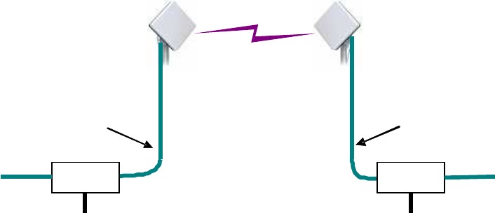
1.6. System Configuration
The operation mode of the WT can choose Slave mode and Master mode.
Point to Point line uses in combination Master and Slave.
WT is supplied a power supply by PoE PSE (Power over Ethernet Power Sourcing
Equipment)
The setting items such as modulation method, the radio frequency channel set it to Master.
These setting items are transmitted into Slave through a radio link.
The user data is transmitted between Master and Slave transparently.
Master implements an SNMP agent function and can communicate with an SNMP manager.
Wireless Terminal (WT)
Slave
Ethernet
Cable (100m max.)
PoE PSE
PoE PSE
100BASE
-
TX/
1000BASE
-
T
100BASE
-
TX/
1000BASE
-
T
Wireless Terminal (WT)
Master
Ethernet
Cable (100m max.)
1-8
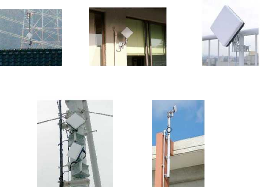
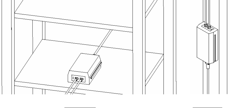
1.7. Installation examples
Figure 1-1 is Installation examples of The WT.
Figure 1-1 Installation examples of the WT

1-9
1.8. Components
Table 1-1 Components List
No.
Name Model Description
1 WT
(Wireless
Terminal)
-NTG-525USL: 24.250-24.450GHz
(FCC [Lch])
-NTG-525EUL: 24.549-25.445GHz
(ETSI [Lch] and FCC [Hch]):
-NTG-525EUH:25.557-26.453GHz
(ETSI [Hch])
The WT is a radio unit that
accommodates all the antenna, radio
transceiver, signal processor and
interface section in the same housing.
It supports 100BASE-TX and
1000BASE-T user interfaces to
connect a personal computer and hub.
1.1
WT mounting
bracket
MPBX46819 The WT mounting bracket is used to
mount the WT at a pole.
Including in WT
2 Antenna
direction
adjustment tool
NKK-163 This is the antenna direction
adjustment tools for the WT.
3 WIPAS2
INSTRUCTION
MANUAL
(CD-ROM)
H-7YZCM5106 INSTRUCTION MANUAL is included
in this CD-ROM
3.1
WIPAS2
INSTRUCTION
MANUAL
H-7YZCM5107 INSTRUCTION MANUAL
Subject to change without notice.
A customer prepares for PoE PSE, Ethernet Cable, and Ground wire.

2-10
2. Specifications
2.1. General
Table 2-1 Specifications
Item WIPAS2 Point to Point System
WT Model Name NTG-525USL NTG-525EUL NTG-525EUH
Frequency Band 24.250-24.450GHz
FCC Band 24.549-25.445GHz
ETSI and FCC Band 25.557-26.453GHz
ETSI Band
Duplex/multiple access TDD ( Flexible DL / UL Ratio )
Modulation system QPSK/16QAM/64QAM ( Adaptive Modulation or Fixed )
Channel spacing 28MHz 56MHz
Occupied bandwidth 26MHz 52MHz
Symbol rate (Selectable) 20M symbol/s, 40M symbol/s
Radio Transmission rate QPSK: 40 Mbps
16QAM: 80 Mbps
64QAM: 120Mbps
QPSK: 80 Mbps
16QAM: 160 Mbps
64QAM: 240Mbps
Data throughput
QPSK: 30 Mbps
16QAM: 60 Mbps
64QAM: 90bps
QPSK: 60 Mbps
16QAM: 120 Mbps
64QAM: 180Mbps
Transmit output power
QPSK: -6 to +14dBm
16QAM: -8.6 to +11.4dBm
64QAM:-9.7 to 10.3dBm
Frequency Stability ±10ppm
Minimum receiving level
(BER=10-6)
After an error
correction
QPSK: -80.5dBm or less
16QAM: -73.5dBm or less
64QAM: -65.5dBm or less
QPSK: -77.5dBm or less
16QAM: -70.5dBm or less
64QAM: -62.5dBm or less
Antenna type and gain (typ) High-gain flat antenna: 31dBi
External Antenna*1:
HPCPE-26 35.7 dBi (30cm)*1
HP2-26 41.1 dBi (60cm)*1
Interface 10BASE-T/100BASE-TX/1000BASE-T
QoS
- Service class: 8 class
- Priority control: Strict Priority Queuing (SPQ)
- Band late control: Policer, Shaper
- Transmitted Buffer size: total 1Mbytes, Each buffer size is configurable
- Service identifier: With VLAN Tag :VLAN COS field
With out VLAN Tag :IPv4 TOS field、IPv6 Traffic Class field, Ether Type (15 types)
MAC address filtering disable
SNMP (agent) SNMP V2,V3,
Private MIB
Maintenance Tool Local & Remote maintenance is possible by Management Tool by Web browser
supported OS: Windows7 , Windows XP
- Main Monitor:
- Monitoring: Event Log / Radio Performance / Link Utilization / Traffic Counter / NE State Information
- QoS and Traffic Control:
- Installation: Antenna Alignment / Packet Transmission Test
- Configuration: Radio / Network / Boot Sector Selection and Initializations / Date and Time /
Configuration Backup / Software Downloading / User Class Password / Frequency Table
Power 20VA (MAX)
Power supply method IEEE802.3at Type2
WT is supplied power by PoE PSE
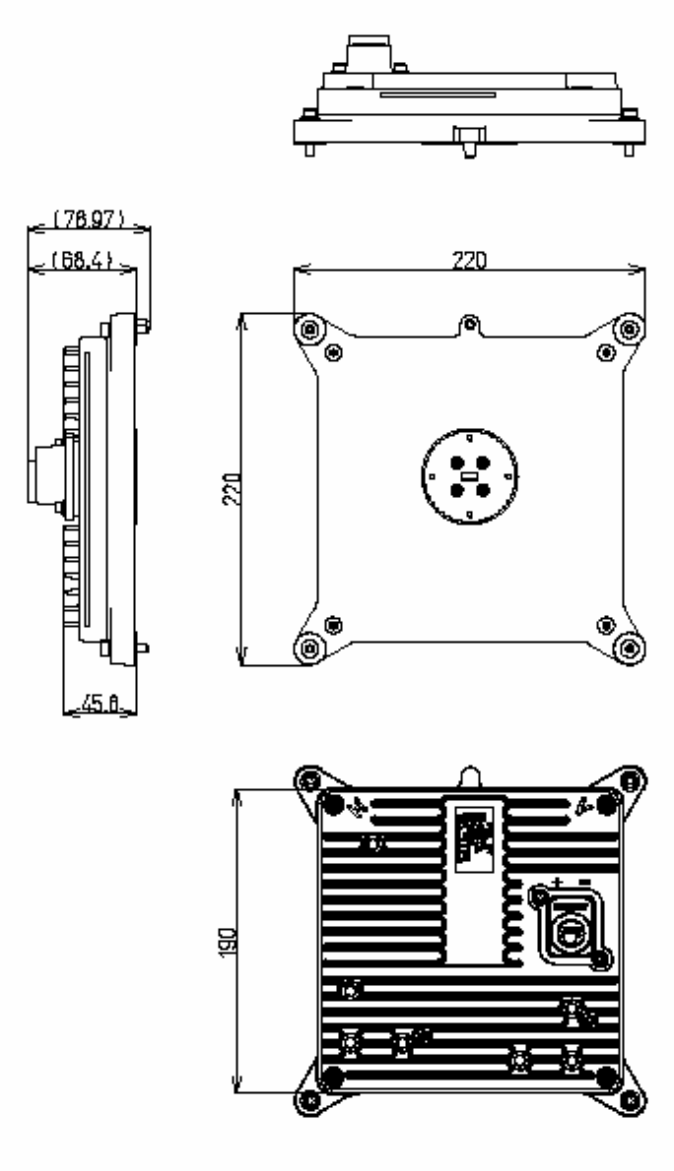
Physical WT Unit (Internal Antenna):Dimensions W190XH190XD52(mm) (not include protuberance)
Weight about 2kg

2-11
WT Unit (External Antenna):Dimensions W220 XH220XD45(mm) (not include protuberance)
Weight about 3kg
Operating Temperature -33degree Celsius - +50degree Celsius
Operating Humidity 20% - 95% non-condensing
waterproofing IP55
storage environment -33degree Celsius - +60degree Celsius
20% - 95% non-condensing
survival wind speed 90m/s non-destructive
40m/s communicatable
Remark*1:JRC doesn't offer External Antenna. Please buy External Antenna directly from Radio Wave which is antenna
bender.
2-12
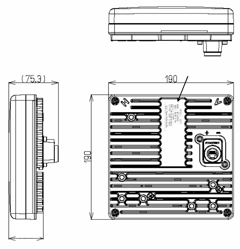
2.2. External Views of the Units
2.2.1. WT
(in mm)
Figure 2-1 External View of the WT
(a)
52
2-13
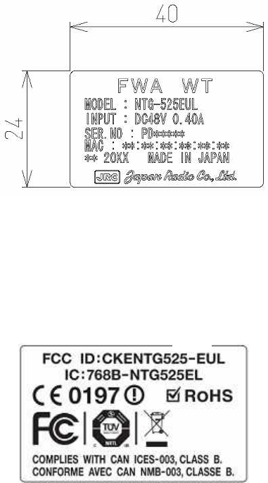
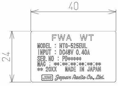
2.2.1.1. WT Nameplate
Nameplate(a)
Nameplate(b)
Figure 2-2 Nameplate
2-14
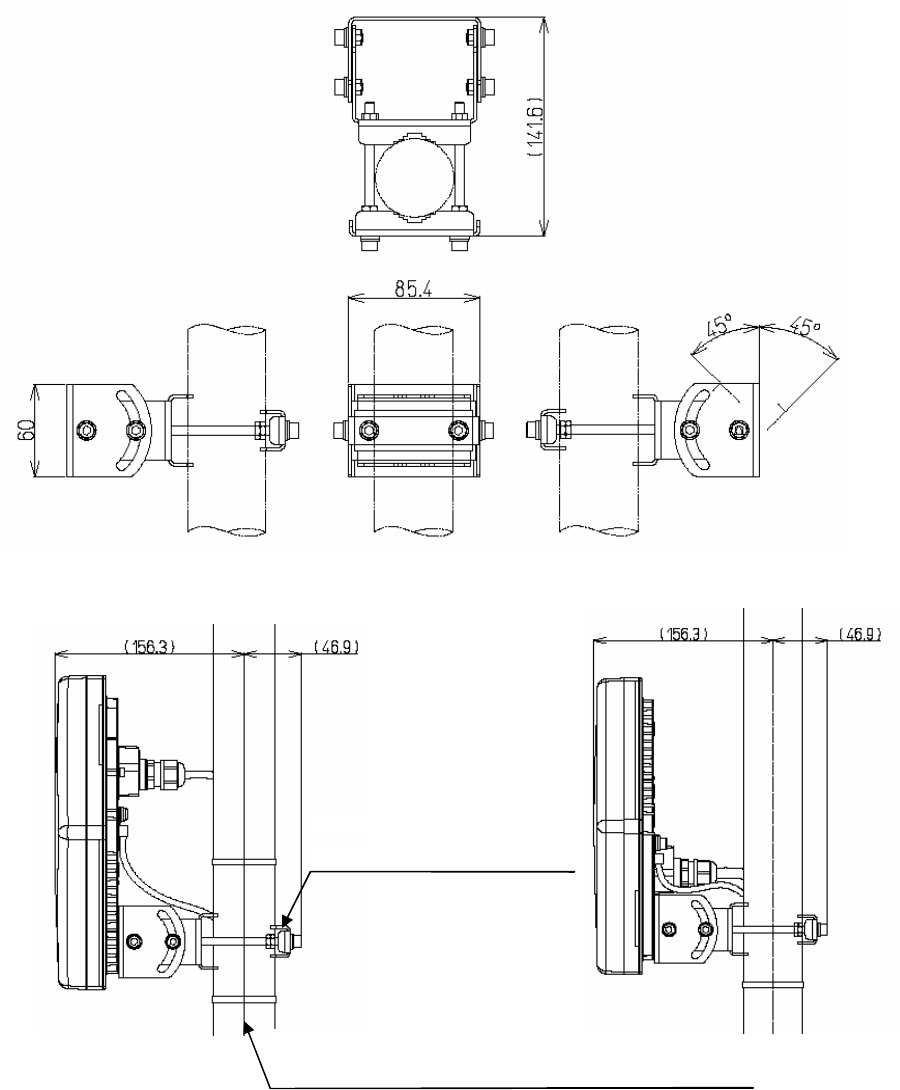
2.2.1.2. WT Mounting Bracket
Figure 2-3 External View of the Outdoor Mounting Brackets for the WT
- Vertical polarization
(Pole diameter is Φ50.8mm)
- Horizontal polarization
(Pole diameter is Φ50.8mm)
WT Mounting Bracket
(Pole mounted in any position)
Pole mounting
(Applicable pole diameter: From Φ25.4mm to Φ50.8mm)
2-15
(in mm)
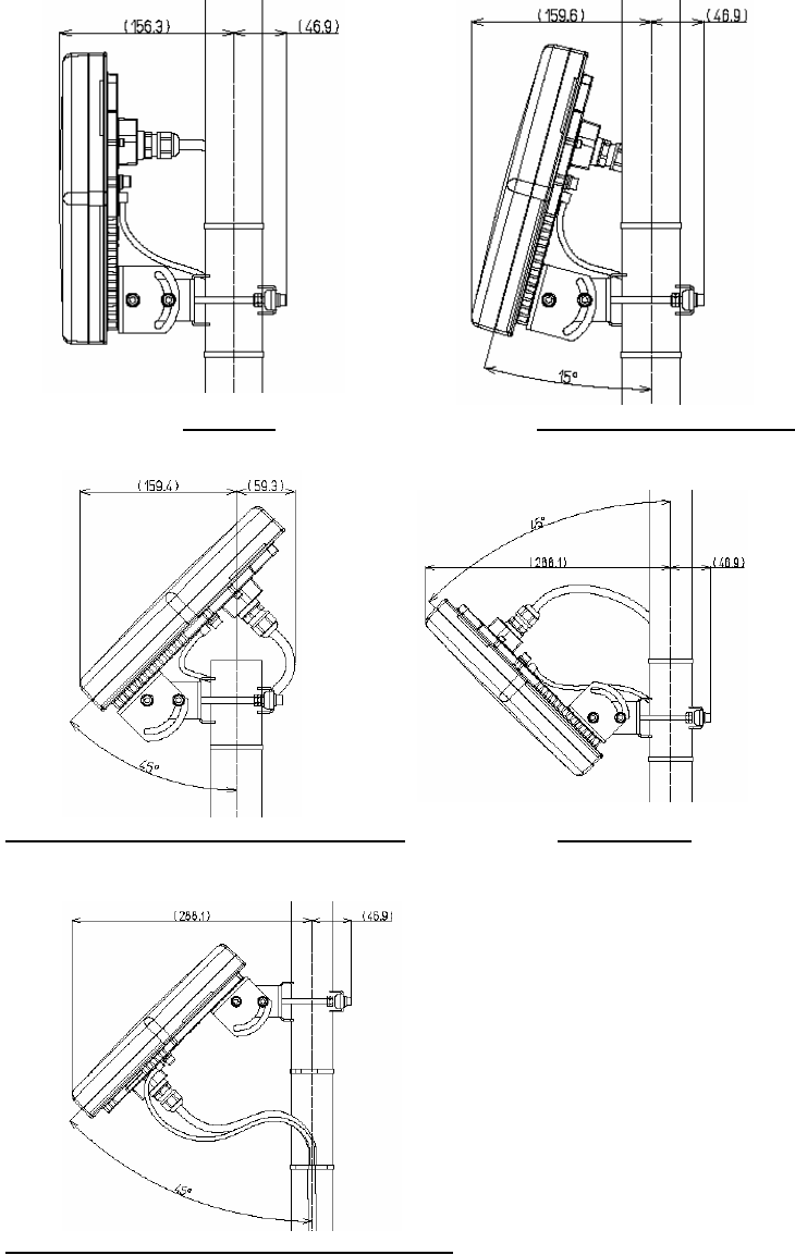
Figure 2-4 Installation example for Vertical polarization(Pole diameter is Φ50.8mm)
Angle of elevation 15degree
Angle of elevation 45degree on the pole top
Angle of elevation 45degree in middle of the pole
Dip 45degree
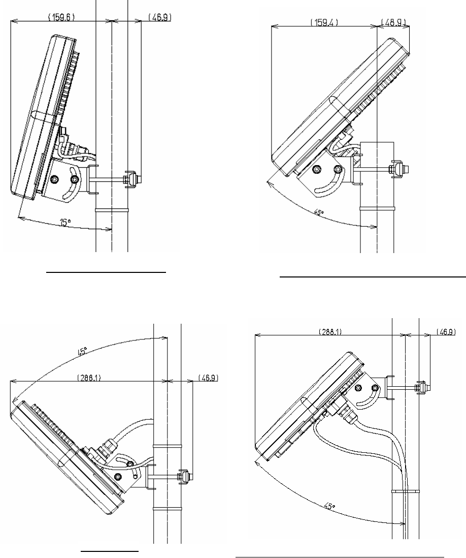
2-16
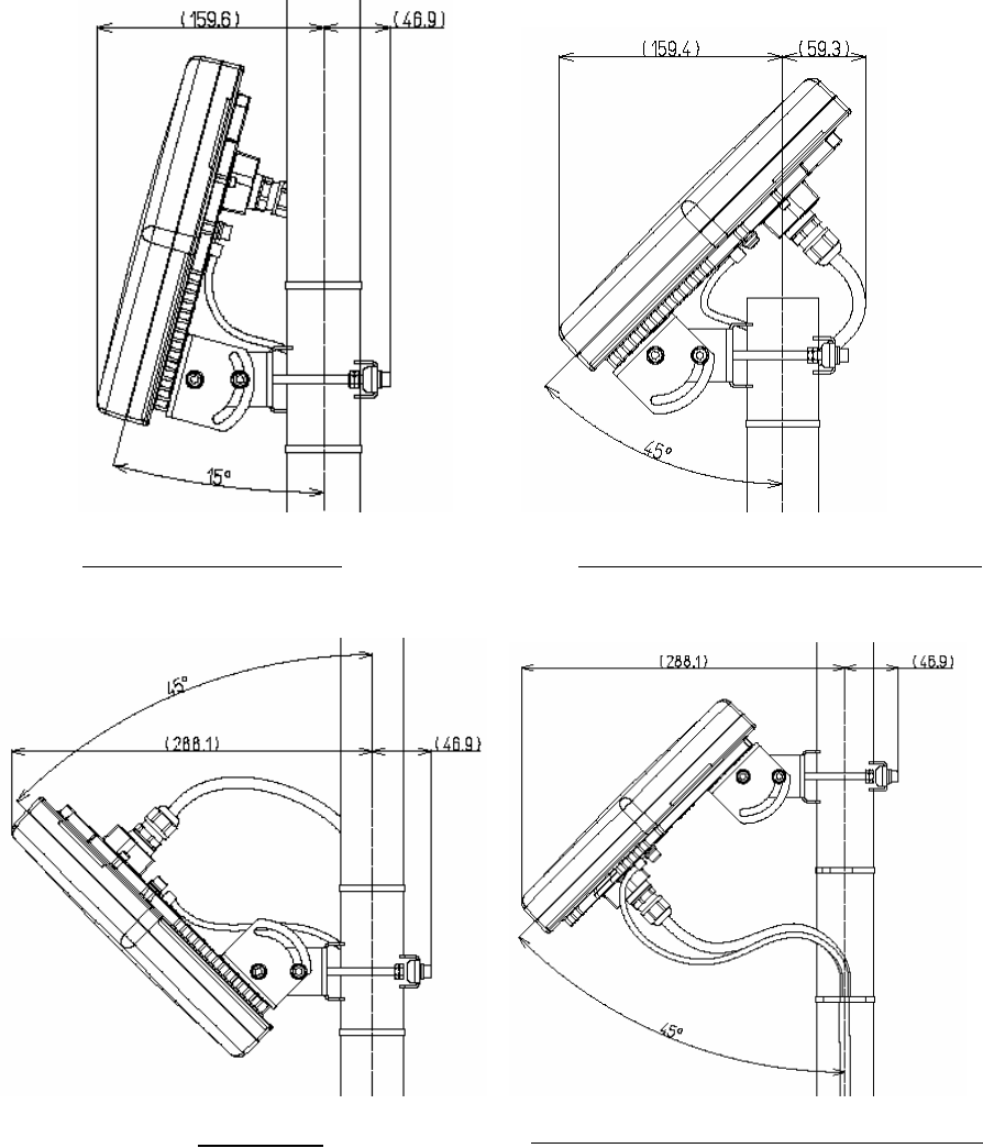
Figure 2-5 Installation example for Horizontal polarization(Pole diameter is Φ50.8mm)
Dip 45degree
Angle of elevation 45degree in middle of the pole
Angle of elevation 15degree
Angle of elevation 45degree on the pole top
2-17
2.2.2. WT (External Antenna Type)
Figure 2-6 External View of the WT (External Antenna Type)
2-18
2.2.2.1. WT (External Antenna Type) Nameplate
Nameplate (a)
Figure 2-7 Nameplate
2-19
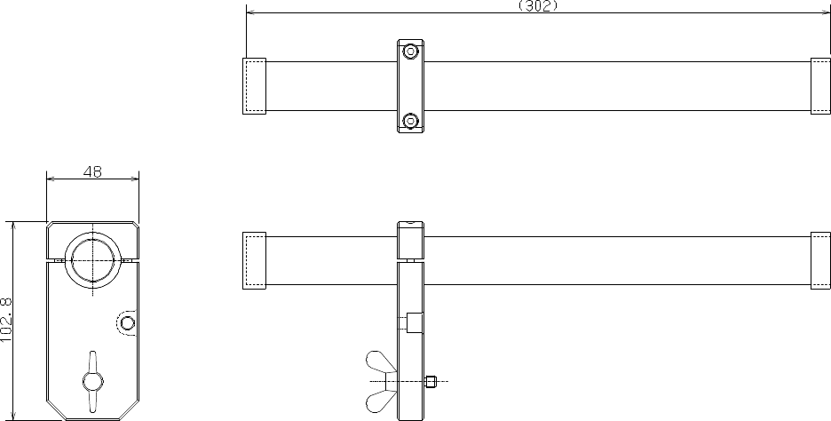
2.2.3. Antenna direction adjustment tool
(in mm)
Shape of the scope is subject to change without notice.
Figure 2-8 Antenna direction adjustment tool
3-20
3. WT
3.1. WT
3.1.1. Overview
The WT consists of the antenna section, RF section, IF section, digital section, interface section
and power supply.
3.1.2. Antenna section
Uses a Triplate planar antennas to make the antenna compact and to provide a high gain. When
you use an WT (external antenna type), you can install a external antenna.
3.1.3. RF section
In the RF section, the transmission IF signals are up-converted into 24-26 GHz-band RF signals
using the local signal, which is generated by multiplying the synthesized oscillator. The next-stage
BPF eliminates unwanted sideband components. The up-converted 24-26 GHz-band RF signals
are amplified up to the desired level then fed to the antenna via the TDD-Switch and the
Waveguide Filter.
The received 24-26 GHz-band RF signals by the antenna are fed in to the LNA via the Waveguide
Filter and the TDD-Switch. The output signals of the LNA are down-converted into IF signals
using the local signal, which is generated by multiplying the synthesized oscillator.
3.1.4. Digital section
The digital section consists of a digital modem, TDD framer, wireless MAC processor, and system
controller. These functionalities are equipped in the ASIC.
The digital modem performs modulation and demodulation of transmitting and receiving burst
signals.
The TDD framer constructs and deconstructs radio frames. It also performs scrambling,
encryption, and error correction functionalities.
The wireless MAC processor converts between the Ethernet frames and the wireless MAC
frames in the radio channel.
The system controller performs operating parameter setting, state monitoring, control and testing.
It also communicates with the opposite WT processer via the radio link.
3-21
3.1.5. Interface section
The interface section provides the physical interfaces of Ethernet for user interface. It has a
lightning surge protector to protect the unit against external surges.
3.1.6. Power supply
The power supply section generates various voltages used within the unit from input power of
PoE PSE.
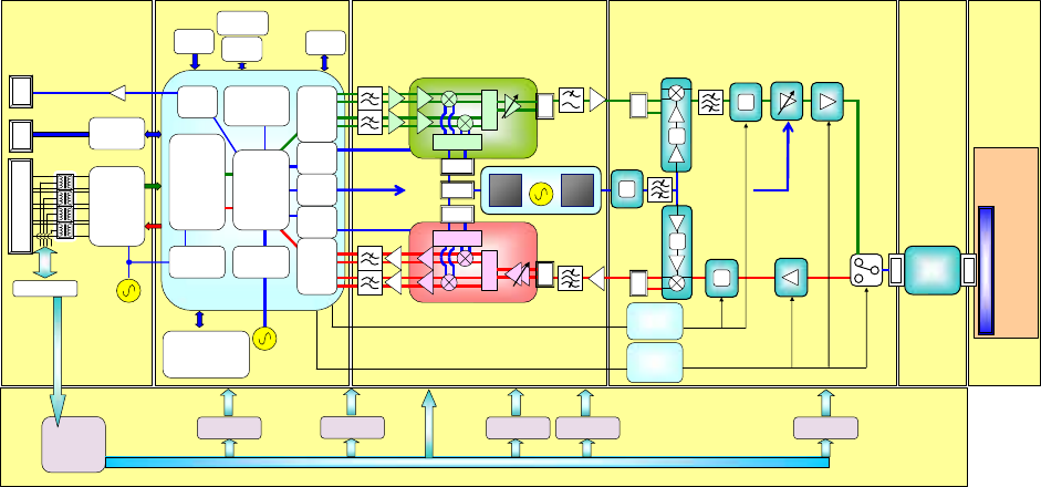
Figure 3-1 is a block diagram of the WT.
BPFIF
RJ-45 [1000BASE-T]
Balun
Quadrature
Demodulator
0/0
0/90
POWER over Ether
Gigabits
Ethernet
Ttansceiver
for
1000BASE-T
100BASE-TX
10Base-T
Gigabits
Ethernet
MAC
CPU
ATPC1
D/A Conv
AGC1
D/A Conv
Quadrature
modulator
0/0
0/90
Balun
Splitter
Balun
SAW_BPF
LPF
RS232C
Drv/Rec
MAINT
PORT
25MHz
SDRAM
128Mbit x32
FROM
64Mbit
Temp
Sensor
ATT
Control
Drivers
Balun
WG
BPF
SYSTEM
RESET
PLL
160/80MHz
PLL
125MHz
SDRAM
for MAC
(256Mbit)
x32
TDDcont
250MHz
High Speed
BaseBand SoC
BBfilter
IF TPC
IF AGC
AGC2
D/A Conv
40MHz
BBfilter
2.4GHz
Synthe
for IF
TCXO
20MHz 3.0GHz
Synthe
for RF
x4
ATT
x2
Balun
LNA
PA
UP Conv
Down Conv
TDD
Control
Drivers
TXATTcont
RXATTcont
ATPC2
D/A Conv
SPI
20/40M
RF
RF TPC
Digital
MODEM
BaseBand
12bit
D/A Conv
BaseBand
10bit
A/D Conv
Balun
ATT
x2
RF TPC
RF TPC
RX
Level
DC/DC
Conv
+5V
+3.3V
+1.0V +5.0V - 5.0V +6.5 V
DC/DC
Converter DC/DC
Converter
Power
DC/DC
Converter
DC/DC
Converter
Interface Digital
+13V
DC/DC
Converter
Figure 3-1 WT Block Diagra
3-22
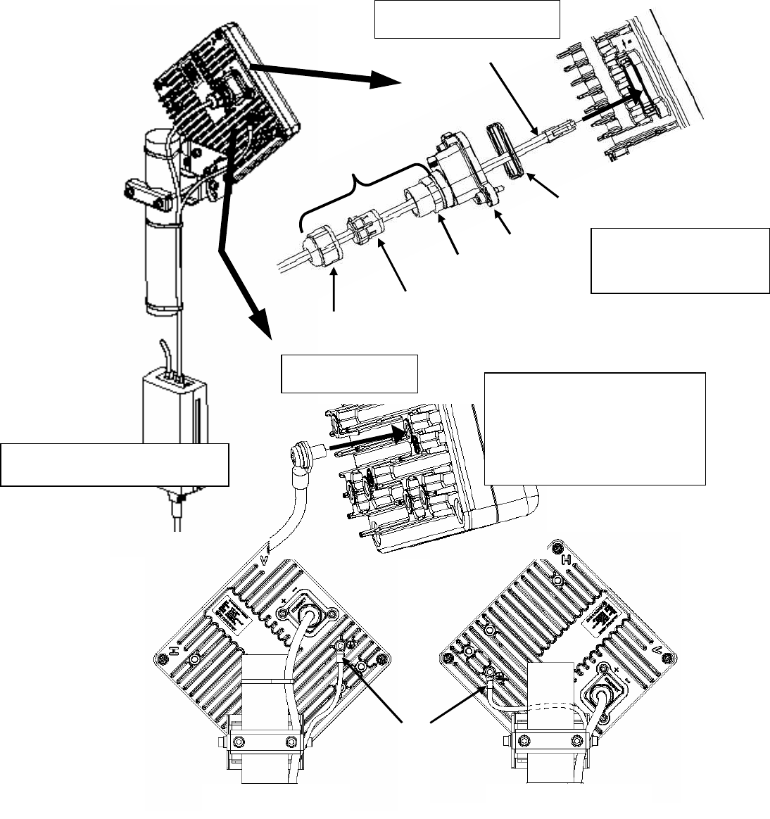
3.1.7. Terminals
3.1.7.1. WT
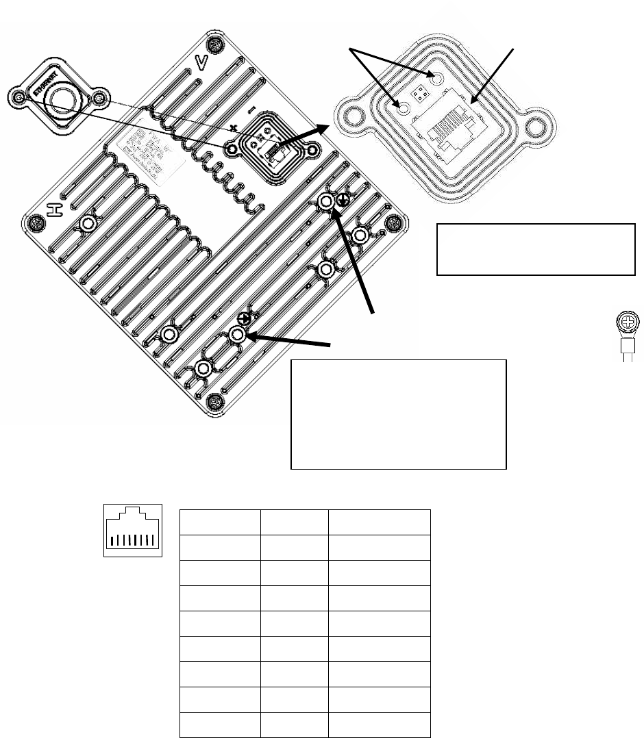
Figure 3-2 Connecting Section of the WT
Pin Assign
DATA PoE
1 TRD+(0)
48V
2 TRD-(0)
48V
3 TRD+(1)
48V(Return)
4 TRD+(2)
48V
5 TRD-(2)
48V
6 TRD-(1)
48V(Return)
7 TRD+(3)
48V(Return)
8 TRD-(3)
48V(Return)
Small Lid
Voltage Monitor Terminal
For Receiving Level Ethernet Connector
FG terminal for Vertical polarization
FG terminal for Horizontal polarization
Small Window
FG Terminal
M6 nut (M6X12SUS)
Tool: Phillip screwdriver (No.3)
Tighten torque: 8.5N・m
You will need a Torx screwdriver
(VESSEL T20H-120) to open
the small
lid
of the WT
8 7 6 5 4 3 2 1
Ethernet Connector Pin Assign

3-23
(1) Ethernet Connector
Contents Connect the user network via. PoE PSE
Interface 1000BASE-T, 100BASE-TX, 10BASE-T
Cable length Maximum 100m.
In case of PoE HUB use:100m is from the WT to PoE HUB
In case of PoE injector use: 100m is from the WT via PoE injector to
HUB. (Because, there is no function of terminate PHY in the PoE
injector)
Connector shape RJ-45
Pin assign - ETHER signal: MDI-X
- POWER: IEEE802.3at Type2
Cable type Ethernet cable for outdoor, STP(Shield Twisted Pair)
Range of applicable
outer diameter φ4.0 mm - 7.0mm
(2) FG Terminal
Contents Connect the ground wire.
Applicable Cable Ground wire 1.6□ (AWG#14)
Applicable terminal FG terminal M6 nut.
Note ground resistance is 100 Ω or less
(3) Voltage Monitor Terminal For Receiving Level
Contents It is a terminal monitoring a receiving level by using voltage circuit
tester.
・ When closing the Small lid, make sure that the rubber packing of the Small lid is free from
any foreign matter.

4-24
4. Management Tool (MT)
The Management Tool (MT) is the Web server function that WT had built-in. The MT performs
setting and the monitoring of the WT. The table below lists the function summary of the MT.
Table 4-1 MT function lists
Items 1 Items 2 Contents
Main Monitor Shows the radio performance, Ethernet counter,
Packet rate in real time
Event Log Shows the alarm log, modulation log.
Radio Performance Shows the radio performance data of past 2-day.
The data are statistics of every 15 minutes.
Link Utilization Shows the Ethernet counter data of past 2-day. The
data are statistics of every 15 minutes.
Traffic Counter Shows the traffic counter. It is a statistic counter
that is period from "Counter Clear" button to "Get
Counter" button
Monitoring
NE State Information Shows all configuration of the network element
(WT).
QoS and Traffic Control Sets the buffer size, TDD control, QoS
configuration, policing, shaping.
Antenna Alignment Carries out the antenna alignment mode Installation
Packet Transmission Test Carries out the packet transmission test
Radio Sets the radio configuration
Network Sets the IP address and SNMP
Boot Sector Selection
and Initializations
Carries out the reset, the changing the boot sector,
and initializing
Date and Time Sets the date and time
Configuration Backup Carries out saving and loading the configuration
file.
Software Downloading Carries out downloading of the software.
User Class Password Sets the password per user class
Configuration
Frequency Table Sets the frequency.
Logout Logout MT

4-25
4.1.1.1. MT system requirements
Table 4-2 MT system requirements
Web browser OS Note
Internet Explorer 8 Windows 7
Windows XP
Screen resolution:
higher than 1024x768 pixels
5-26
5. INSTALLING A POINT-TO-POINT SYSTEM
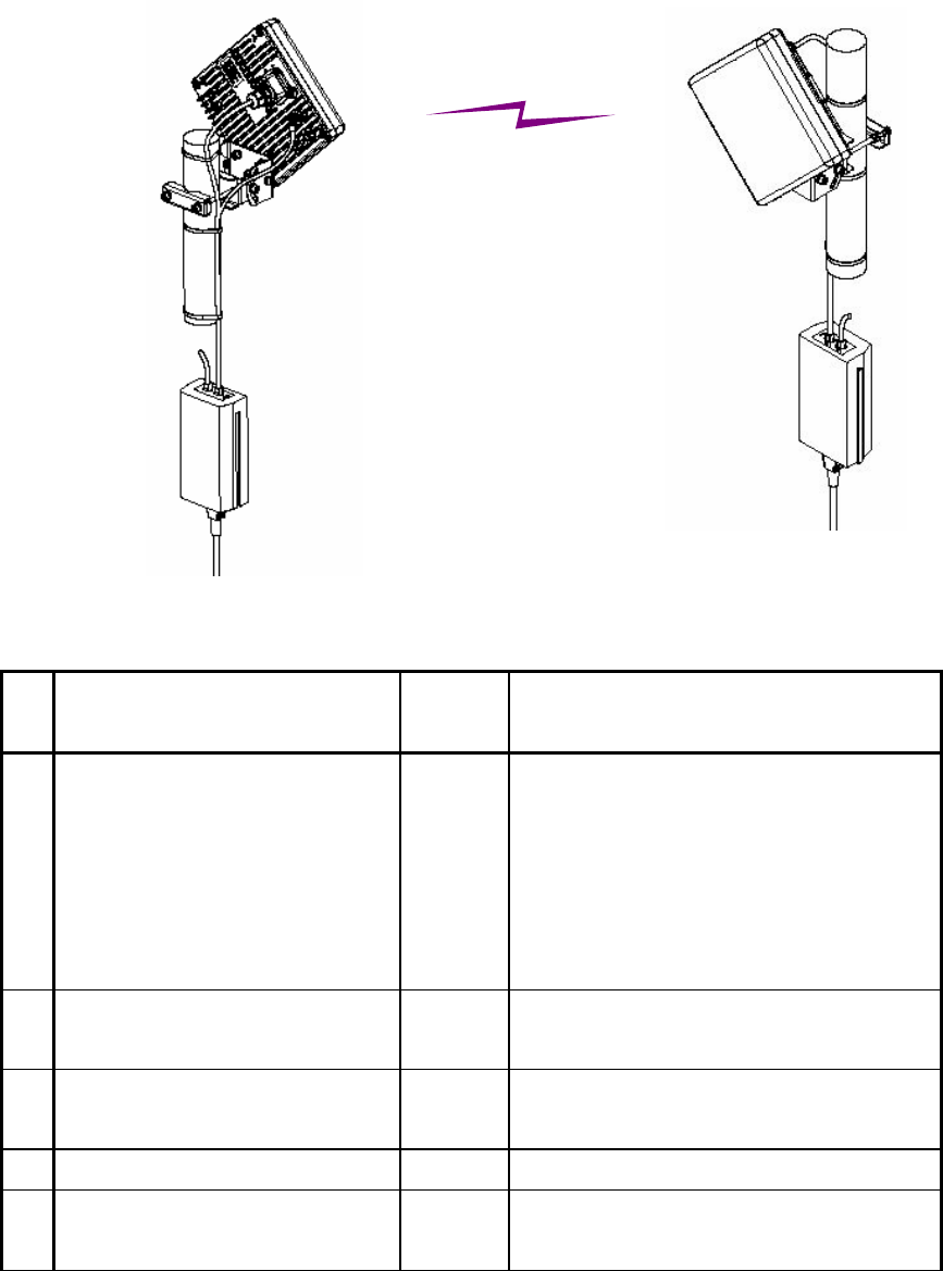
5.1. Overview and installation flow
Figure 5-1 installation Configuration
Table 5-1 Installation components preparing by customer
No
components Quantity
per WT
contents
1 PoE PSE
(Power over Ethernet Power
Sourcing Equipment)
1 - IEEE-802.3at TYPE2
- PoE Injector or PoE HUB
- Surge protection type is recommended
for the purpose of surge protection for
the user devise. (WT has the surge
protection circuit inside)
2 Ethernet Cable 1
(WT to PoE PSE)
1 - CAT-5e cable is recommended
- Straight cable
3 Ethernet Cable 2
(PoE PSE to PC)
1 - CAT-5e cable is recommended
4 Ground weir with FG terminal 1 - Ground resistance is 100Ω or less
5 Pole 1 - Applicable pole diameter: From
Φ25.4mm to Φ50.8mm
To PC
WT (Master)
1. PoE PSE
2. Ethernet Cable 1
3. Ethernet Cable 2
4. Ground weir with
FG terminal
WT (Slave)
1. PoE PSE
3. Ethernet Cable 2
To PC
4. Ground weir with
FG terminal
2. Ethernet Cable 1
5. Pole
5. Pole
5-27
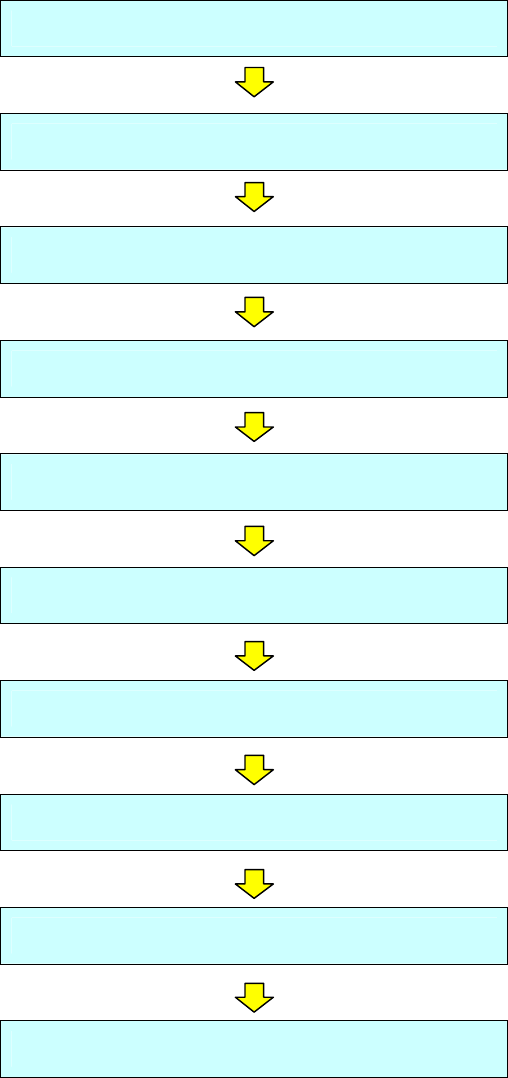
Figure 5-2 P to P installation flow
Start the Maintenance Tool
Configure the WT (master)
Configure the WT (slave)
Installing the WT
Installing the PoE PSE (master/slave)
Connecting Cables to the WT (master/slave)
Waterproofing WT Small lid
Testing
Check sheet
Finish
5-28
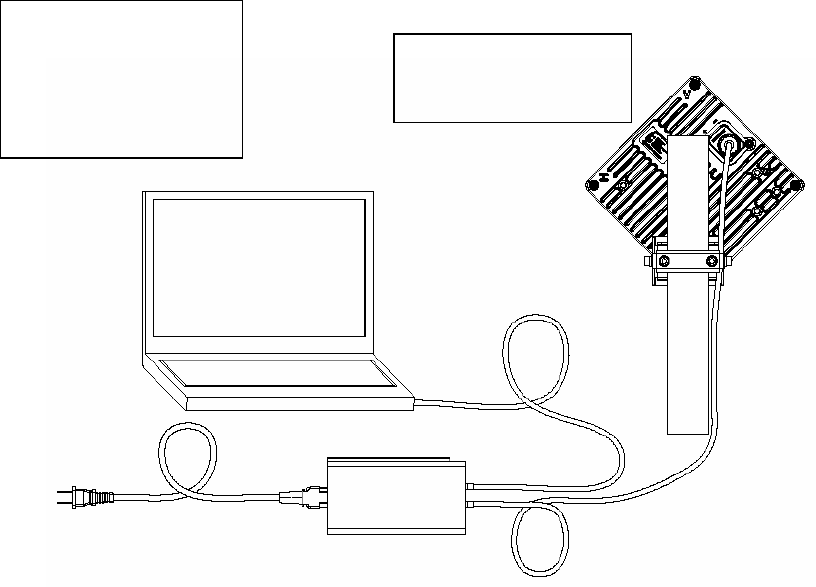
5.2. Start the Maintenance Tool
Connect WT to PC. (Figure 5-3)
Start WEB browser and input “http://192.168.1.100” (initial) into an address column and push the
ETNER key.
A login screen of the Management Tool (MT) is displayed on WEB browser.
After select a login class, input a password to start MT. (Login class: admin or installation)
Figure 5-3 Connection
For Master
IP address: 192.168.1.200
Subnet mask: 255.255.255.0
For Slave
IP address: 192.168.1.201
Subnet mask:255.255.255.0
Initial values
IPaddress:192.168.1.100
Subnetmask:255.255.255.0
Maintenance Tool
Ethernet cable (Straight)
Ethernet cable (Straight)
PoE PSE
・ When changing the IP address of the unit, please input the IP address that was
changed
・ When changing the IP address of the unit, restart the power of the hub if the unit is
connected to the management tool via a hub (because MAC address learning may
fail and the connection may be dropped).
5-29
5.3. Configure the WT (master)
Set the Master configurations with the Maintenance Tool.
Step1 Select the Configuration>Radio configuration tab
- Operating Mode :Set the P-P(Master)
- Symbol Rate :Set 40MHz or 20MHz
- Frame ID :Set the Frame ID same as a Slave(1∼65535)
- Encryption Parameter:Set the Encryption Parameter same as a Slave
(0-22 half width alphabet or digit character)
- Click the Setup button. "Setup" makes configuration changes. These changes are
reflected after Reset.
- Network Element Name:Set Network Element Name. (0-20 full width or half width
alphabet)
- FREQUENCY-CH: Set Frequency CH.
You should register the Frequency CH beforehand on “Frequency Setting” screen.
Configuration> “Frequency Setting” screen.
- Modulation: Set adaptive modulation or fixed modulation. If set adaptive modulation, set
highest modulation (down/ up link). If set fixed modulation, set modulation (down/up link) .
- ATPC: Set Enable (ATPC: automatic transmit power control) or Disable (MTPC: manual
transmit power control). If disabled (MTPC), set MTPC Level (-6 - +14dBm).
Slave MTPC is configured in Slave.
- RF Transmission: Set Enable or Disable (Master and Slave).
- Click the Setup button.
5-30
Figure 5-4 Radio configuration tab (master)
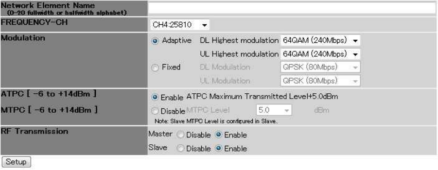
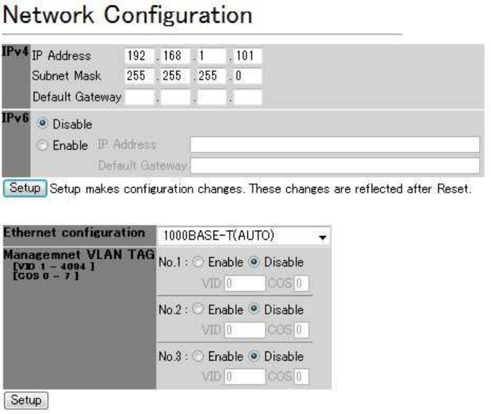
Step2 Select the Configuration>Network Configuration tab.
- IPv4:Set IP address, subnet mask and default gateway
- IPv6:Set Disable or Enable. If enabled, set IP address, default gateway
- Click the Setup button. "Setup" makes configuration changes. These changes are
reflected after Reset.
- ETHERNET Configuration:Set the interface class 1000BASE-T(AUTO)、
1000BASE-T(Fixed), 1000BASE-T(AUTO), 100BASE-TX/FULL(FIXED)、
100BASE-TX(AUTO) or 100BASE-TX/HAFE(Fixed)
- Management VLAN TAG: Set Enable or Disable. If enabled, set VID, COS
- OpS1-3: Set Enable or Disable. If enabled , set IP address (IPv4 or IPv6)
- Community name (SNMP v2)1-3: Set the GET / SET community name for each OpS1-3.
- User name (SNMP v3) 1-3: Set user name, authentication protocol, authentication
password, encryption protocol, encryption password and access control for each OpS1-3.
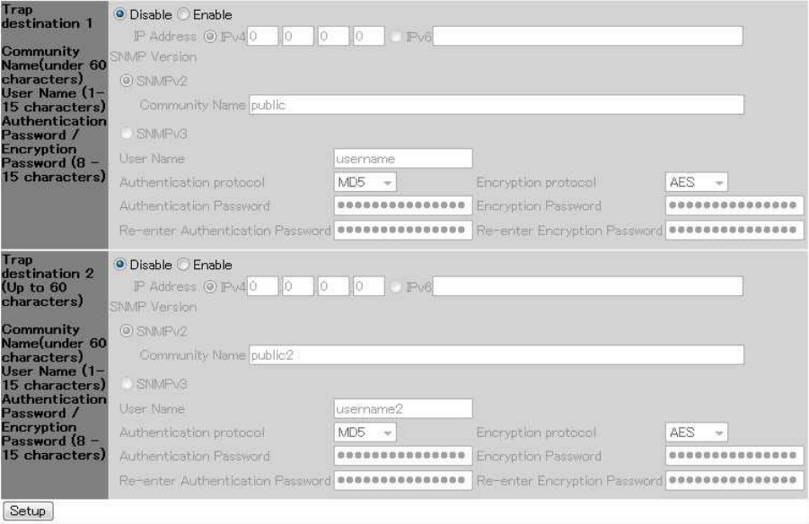
- Trap destination 1-2: Set Enable or Disable. If enabled, set IP address (IPv4 or IPv6) and
SNMP Version (v2 or v3).
- Click the Setup button.
The basic configuration of the WT (Master) is completed by the above and works.
5-31
5-32
Figure 5-5 Network Configuration tab (master)
if necessary, set the following setting.
Step3: Select the QoS and Traffic control tab
- Set Buffer size, COS assignment for Management Communication between Master and
Slave, QoS Priority Class, TDD control, Slave QoS Priority Mapping, Policing Rate, and
Shaping Rate
Step4: Select the Configuration> Date and Time tab
- Set Date and time
5-33
5.4. Configure the WT (slave)
Set the Slave configurations with the Maintenance Tool.
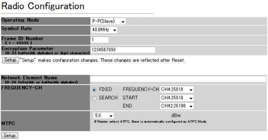
Step1 Select the Configuration>Radio configuration tab
- Operating Mode :Set the P-P(Slave)
- Symbol Rate :Set 40MHz or 20MHz
- Frame ID :Set the Frame ID same as a Master(1∼65535)
- Encryption Parameter:Set the Encryption Parameter same as a Master
(0-22 half width alphabet or digit character)
- Click the Setup button. "Setup" makes configuration changes. These changes are
reflected after Reset.
- Network Element Name:Set Network Element Name. (0-20 full width or half width
alphabet)
- FREQUENCY-CH: Set Fixed or SEARCH. If fixed, set Frequency CH. If SEARCH, set
start CH and end CH.
You should register the Frequency CH beforehand on “Frequency Setting” screen.
Configuration> “Frequency Setting” screen.
- MTPC: Set MTPC (manual transmit power control) Level (-6 - +14dBm).
If Master is selected ATPC, Slave is automatically configured as ATPC Mode.
- Click the Setup button.
Figure 5-6 Radio configuration tab (Slave)
5-34
Step2 Select the Configuration>Network Configuration tab.
- IPv4:Set IP address, subnet mask and default gateway
- IPv6:Set Disable or Enable. If enabled, set IP address, default gateway
- Click the Setup button. "Setup" makes configuration changes. These changes are
reflected after Reset.
- ETHERNET Configuration:Set the interface class 1000BASE-T(AUTO)、
1000BASE-T(Fixed), 1000BASE-T(AUTO), 100BASE-TX/FULL(FIXED)、
100BASE-TX(AUTO) or 100BASE-TX/HAFE(Fixed)
- Management VLAN TAG: Set Enable or Disable. If enabled, set VID, COS
- Click the Setup button.
The basic configuration of the WT (Slave) is completed by the above and works.
Figure 5-7 Network Configuration tab (Slave)
if necessary, set the following setting.
Step3: Select the QoS and Traffic control tab
- COS assignment for Management Communication from Slave to Master.
5-35
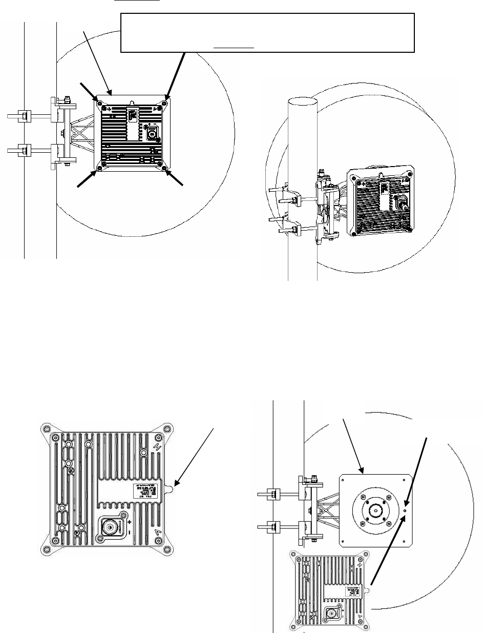
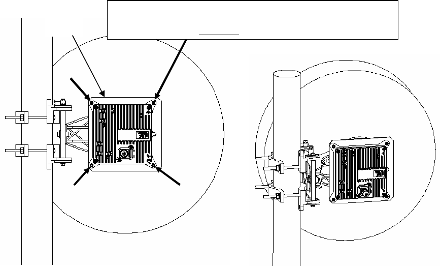
5.5. Installing the WT
5.5.1. Installing the WT (master/slave)
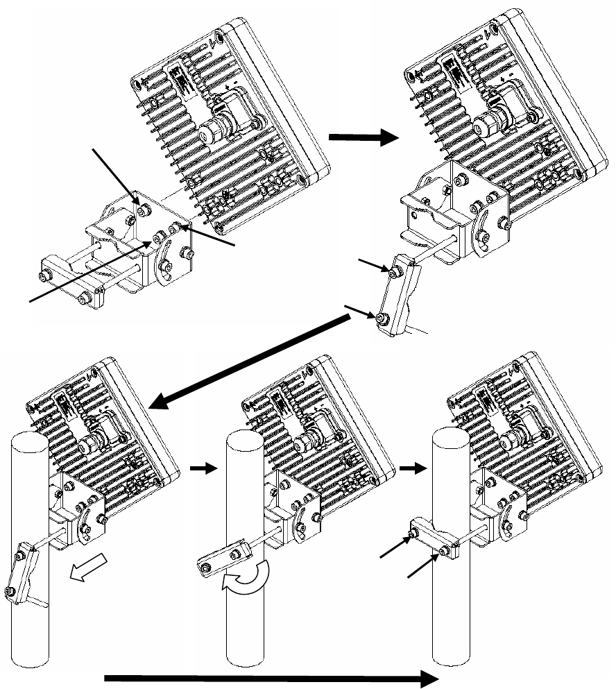
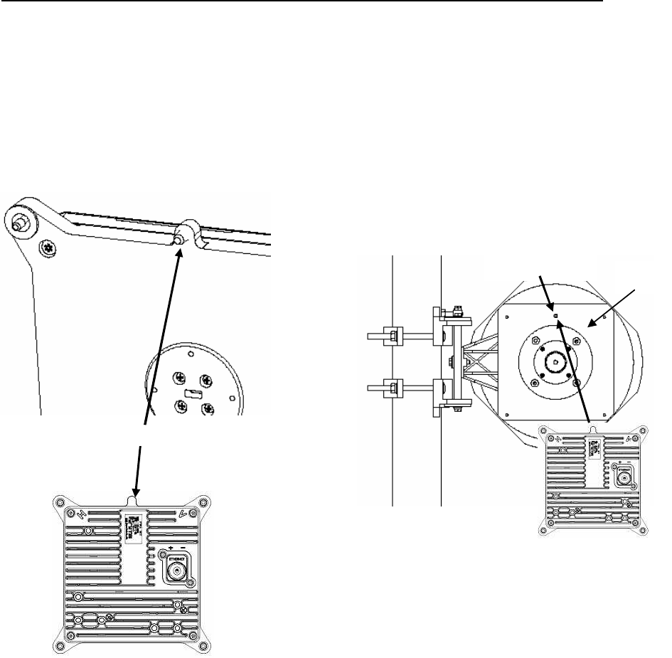
Step1 Attach the WT mounting bracket to the WT using the bolts (a), (b) and (c).
You can install the WT either for vertical or horizontal polarization.
Step2 Secure the WT mounting bracket to the pole using the bolts.
Due to prevent a fall, Bolt (d) removes it. Bolt (e) does not remove it.
Applicable pole diameter: From Φ25.4mm to Φ50.8mm
Figure 5-8 Installing the WT
(a)
(b)
(c)
(d)
(e)
(d)
(e)
5-36
A builder prepares a steel pipe by the installation place (a wall, a pole or etc.), and it install.
Installation example is shown below.
Figure 5-9 Installation example for vertical polarization (pole diameter is Φ50.8mm)
Angle of elevation 15degree
Dip 45degree
Angle of elevation 45degree on the pole top
Angle of elevation 45degree in middle of the pole
Horizontal
5-37
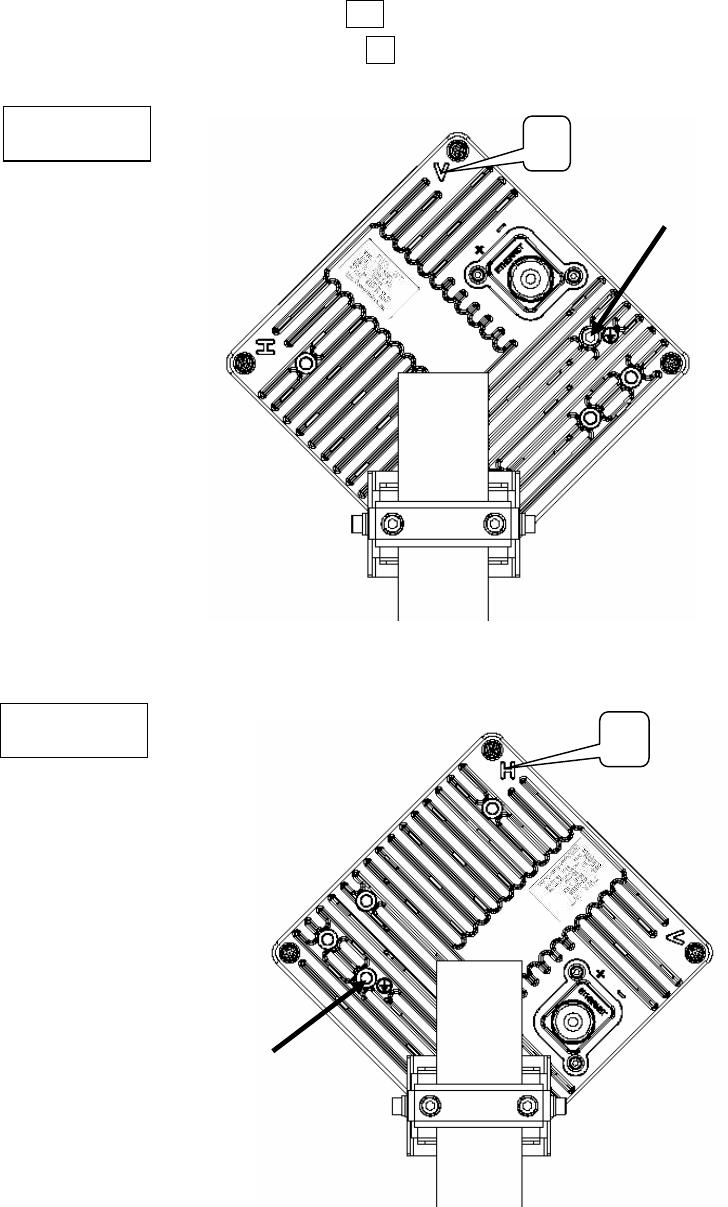
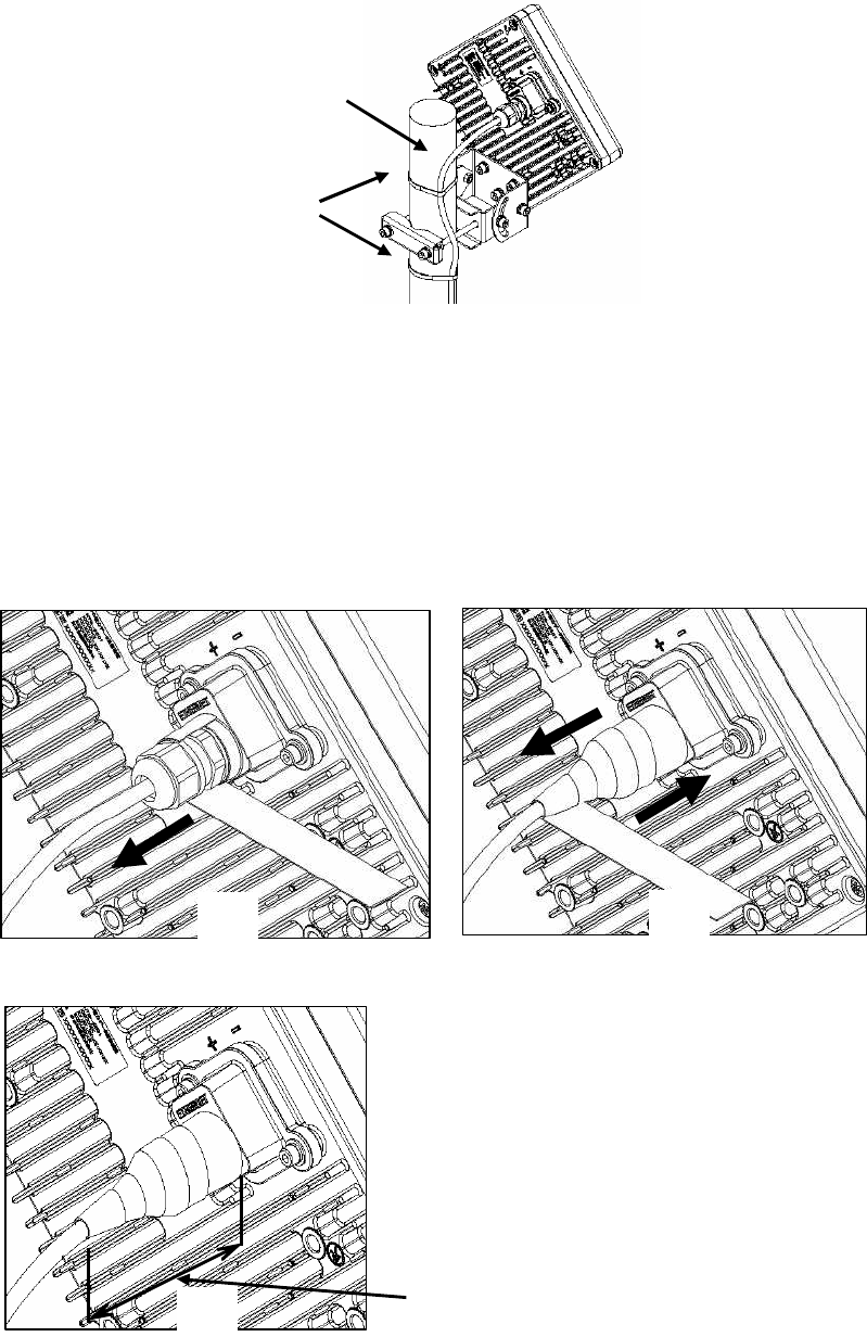
5.5.2. Setting the WT for Vertical or Horizontal Polarization
Rotate the antenna ninety degrees to choose between vertical or horizontal polarization
For vertical polarization, position V at the top.
For horizontal polarization, position H at the top.
Figure 5-10 Vertical Polarization
Figure 5-11 Horizontal Polarization
Vertical
Horizontal
V
FG terminal for Vertical
H
FG terminal for Horizontal
5-38
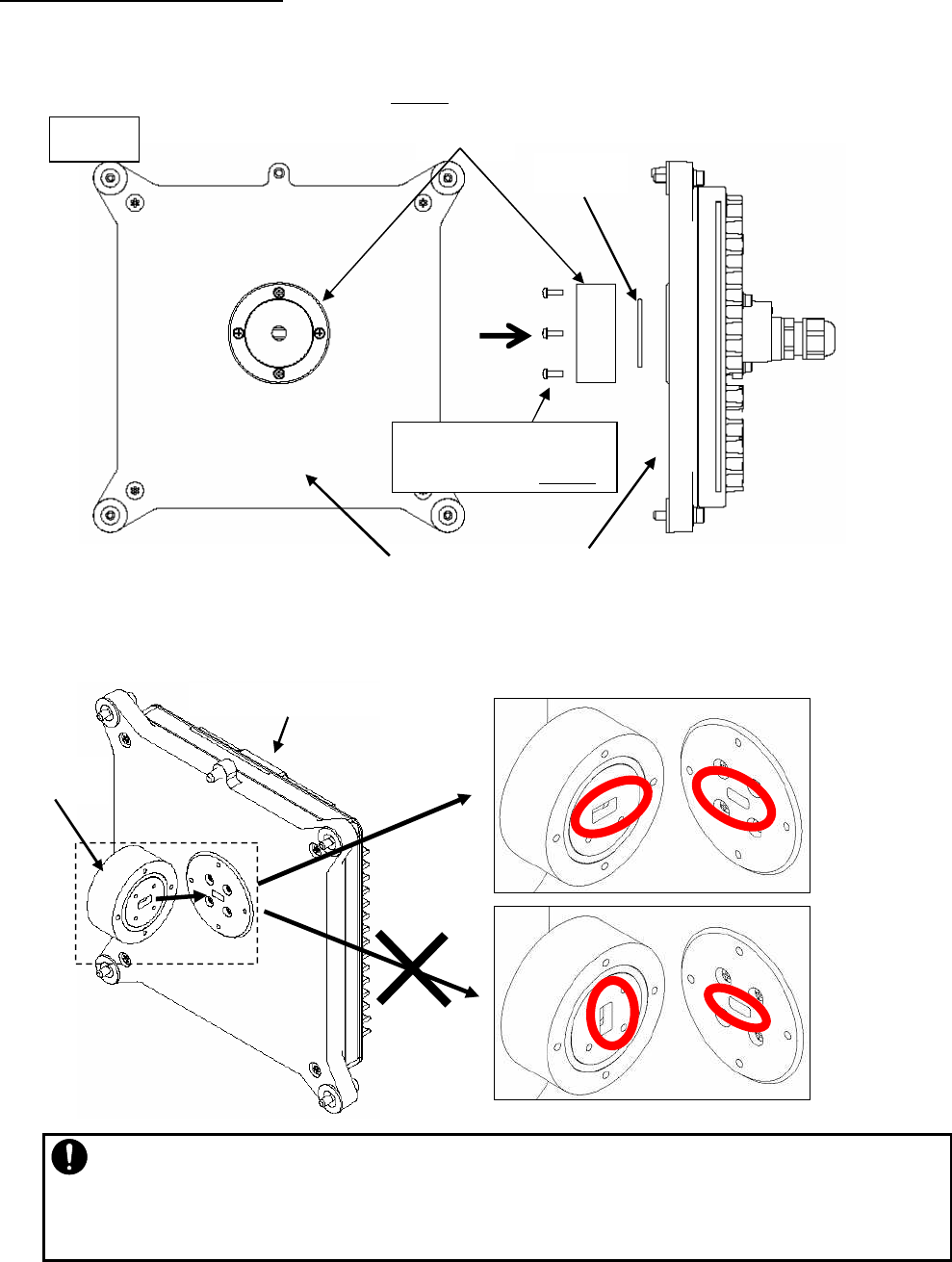
5.6. Installing the WT (External Antenna Type)
5.6.1. Installing Φ30cm Antenna in WT (External Antenna Type)
1. Φ30cm antenna (HPCPE-26J : RADIO WAVE, INC ) installation procedure
1) According to the antenna manual of RADIO WAVES, INC., set it up on the pole.
Figure 5-12 Φ30cm antenna of RADIO WAVES, INC.
2) Spread specified grease on the O-ring.
The spreading method depends on the manual of RADIO WAVES, INC..
Figure 5-13
O-ring
5-39
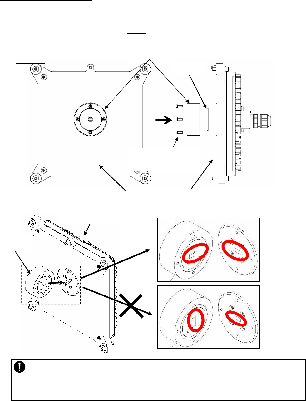
2. WT installation procedure
Attach the antenna adaptor to the WT with the O-ring using four M3 screws. (Figure 6-12 & Figure 6-13)
These (adaptor, the O-ring, M3 screws with Washers x 4 paces) are attached articles of the antennas of
RADIO WAVES, INC. Tightening torque:0.6 N・cm
Figure 5-14
Figure 5-15
O-ring
Adaptor
WT
WT (External Antenna Type)
4 x M3 screws with Washers
Tightening torque:0.6 N・m
OK
NG
WT (External Antenna Type)
Adaptor
・ When you attach the antenna adaptor to the WT, it should take the matched shape of each
other.
・ If it takes the unmatched shape of each other, the radio can not work normally.
5-40
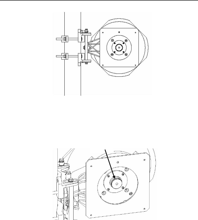
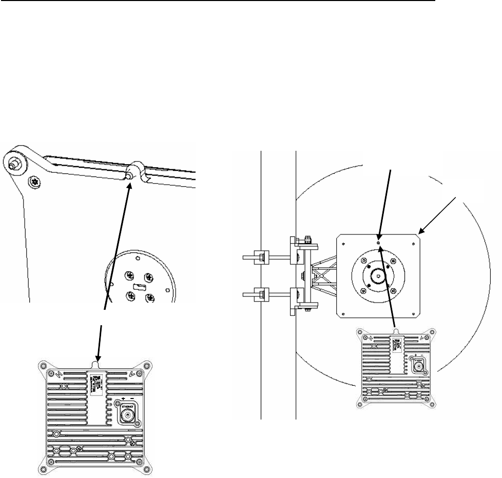
3. Installed WT to an antenna for choosing vertical or horizontal polarization
Rotate the WT ninety degrees to choose between vertical or horizontal polarization.
1) Vertical polarization
When using the V (Vertical) polarization, the guide pin of the WT should be turned to right above and
inserted into the V guide hole of the plate.
Figure 5-16 Vertical polarization
Figure 5-17
V guide hole Plate
Guide pin
5-41
After inserting the guide pin of the WT into the guide hole, presses the WT to the plate.
While you are pressing the WT, you must be tightening the four M5 screws which included in WT.
Tightening torque:2.7 N・cm
Figure 5-18 Installed WT to an antenna for vertical polarization
2) Horizontal polarization
When using H (Horizontal) polarization, the guide pin of the WT should be rotated to the right and
inserted into the H guide hole of the plate.
Figure 5-19 Figure 5-20 Horizontal polarization
Plate
4 x M5 screws / tool: Allen wrench (Width across flats 4)
Tightening torque 2.7 N・m
Plate
H guide hole
Guide pin
5-42
After inserting the guide pin of the WT into the guide hole, presses the WT to the plate.
While you are pressing the WT, you must be tightening the four M5 screws which included in WT.
Tightening torque:2.7 N・cm
Figure 5-21 Installed WT to an antenna for horizontal polarization
Plate
4 x M5 screws / tool: Allen wrench (Width across flats 4)
Tightening torque 2.7 N・m
5-43
5.6.2. Installing Φ60cm Antenna in WT (External Antenna Type)
1. Φ60cm antenna (HP2-26J : RADIO WAVE, INC ) installation procedure
1) According to the antenna manual of RADIO WAVES, INC., set it up on the pole.
Figure 5-22 Φ60cm antenna of RADIO WAVES, INC.
2) Spread specified grease on the O-ring.
The spreading method depends on the manual of RADIO WAVES, INC..
Figure 5-23
O-ring
5-44
2. WT installation procedure
Attach the antenna adaptor to the WT with the O-ring using four M3 screws. (Figure 6-22 & Figure 6-23)
These (adaptor, the O-ring, M3 screws with Washers x 4 paces) are attached articles of the antennas of
RADIO WAVES, INC. Tightening torque:0.6 N・cm
Figure 5-24
Figure 5-25
OK
NG
WT (External Antenna Type)
Adaptor
・ When you attach the antenna adaptor to the WT, it should take the matched shape of each
other.
・ If it takes the unmatched shape of each other, the radio can not work normally.
O-ring
Adaptor
WT
WT (External Antenna Type)
4 x M3 screws with Washers
Tightening torque:0.6 N・m
5-45
3. Installed WT to an antenna for choosing vertical or horizontal polarization
Rotate the WT ninety degrees to choose between vertical or horizontal polarization.
1) Vertical polarization
When using the V (Vertical) polarization, the guide pin of the WT should be turned to right above and
inserted into the V guide hole of the plate.
Figure 5-26 Vertical polarization
Figure 5-27
V guide hole
Plate
Guide pin
5-46
After inserting the guide pin of the WT into the guide hole, presses the WT to the plate.
While you are pressing the WT, you must be tightening the four M5 screws which included in WT.
Tightening torque:2.7 N・cm
Figure 5-28 Installed WT to an antenna for vertical polarization
2) Horizontal polarization
When using H (Horizontal) polarization, the guide pin of the WT should be rotated to the right and
inserted into the H guide hole of the plate.
Figure 5-29 Figure 5-30 Horizontal polarization
Plate
4 x M5 screws / tool: Allen wrench (Width across flats 4)
Tightening torque 2.7 N・m
Plate
H guide hole
Guide pin
5-47
After inserting the guide pin of the WT into the guide hole, presses the WT to the plate.
While you are pressing the WT, you must be tightening the four M5 screws which included in WT.
Tightening torque:2.7 N・cm
Figure 5-31 Installed WT to an antenna for horizontal polarization
Plate
4 x M5 screws / tool: Allen wrench (Width across flats 4)
Tightening torque 2.7 N・m
5-48
5.7. Adjusting the antenna Direction of the WT
5.7.1. Adjusting the Antenna Direction of the WT
This section describes the procedure for adjusting the antenna direction.
When adjusting the direction of the WT antenna, use the “Antenna direction adjustment tool”
together with Maintenance Tool.
Step 1: Connection between WT (master/slave) and Management Tool and display the Receiving
Level.
See Subsection 5.7.1.1
- In case of near-distance installation (When receive level become more than -30dBm),
Enable the setting of the short distance mode.
Step 2: Rough adjustment for the WT (Master)
- Install the Antenna direction adjustment tool.
- See Subsection 5.7.1.2
- Remove the Antenna direction adjustment tool.
- When using the Antenna direction adjustment tool, See Subsection 5.7.1.3.
Step 3: Rough adjustment for the WT (Slave)
- Install the Antenna direction adjustment tool.
- See Subsection 5.7.1.2
- Remove the Antenna direction adjustment tool.
- When using the Antenna direction adjustment tool, See Subsection 5.7.1.3.
Step 4: Fine adjustment for the WT (Slave)
- See Subsection 5.7.1.4
Step 5: Fine adjustment for the WT (Master)
- See Subsection 5.7.1.4
Step 6: Verification
- After fine adjustment, use the Management Tool to final check the receive level.
If the receive level value is within the standard range, the procedure for adjusting the
antenna direction has been completed.
If the receive level value is lower than a standard value, you need to perform Steps 4 and
5 again.
Step 7: Exit the Maintenance Tool
5-49
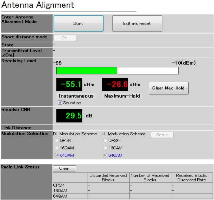
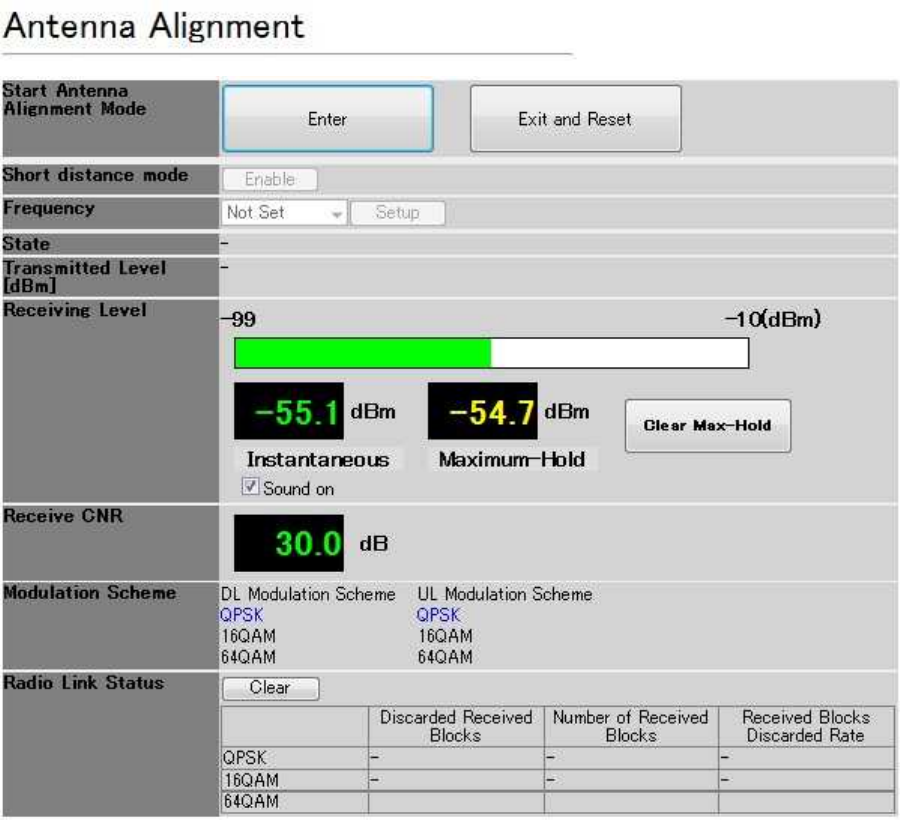
5.7.1.1. Measuring the receive level
(1) As shown in Figure 5-32, connect the Management Tool (PC) to the WT. (login class: admin or
installation)
Figure 5-32 Connecting the Maintenance Tool
(2) Measuring the receive level the WT (Master / Slave)
Step1 Select the Installation > Antenna Alignment tab
Step2 Click the Enter button to change the Antenna Alignment mode
When distance is a short (approximately less than 100m), change the short distance mode
into Enable (add -20dB attenuation for transmitted level)
Only for Slave, set the Frequency CH same as Master frequency CH.
Step3 The initial value of the modulation scheme is QPSK in the direction adjustment mode.
Usually use QPSK in Antenna Alignment mode
If you need, you can set the Modulation scheme (down link / up link).
QPSK、16QAM、64QAM
Click the Setup button to change the modulation scheme.
The modulation scheme of Down link and Up link usually set it in the same value.
Step4 Measure the "Receiving Level"
For Master
IP address: 192.168.1.200
Subnet mask: 255.255.255.0
For Slave
IP address: 192.168.1.201
Subnet mask:255.255.255.0
Initial values
IPaddress:192.168.1.100
Subnetmask:255.255.255.0
Maintenance Tool
Ethernet cable (Straight)
Ethernet cable (Straight)
PoE injector
5-50
The Receiving level aims for a direction adjustment mode level of the graph (ATPC OFF)
about "5.7.2 The receive level and the distance"..
In addition, it becomes a normal operation mode when you finish a direction adjustment
mode. The receiving level is optimized by ATPC function.
Therefore, the MT display level of the receiving level becomes the normal operative value
of the graph (ATPC ON) about "5.7.2 The receive level and the distance".
You can confirm the change of the Receiving Level in high (Receiving Level is high) / low
(Receiving Level is low) of the sound when you turn on “sound on” button. The
correspondence OS is Windows XP. This function does not work in Winodws7.Sound
function works on WINDOWS XP.
Step5 After Antenna Alignment, measure the Received Blocks Discarded Rate.
Select the downlink modulation scheme and the uplink modulation scheme (Only Master)
QPSK, 16QAM, 64QAM
Usually set the downlink and the uplink for the same modulation scheme.
Step6 Check the Received Blocks Discarded Rate
Push the Clear button to reset a counter and start the measurement. Update the
measurements automatically.
Step7 END the Antenna Alignment,
Click the “End and Reset” button to finish the Antenna Alignment mode
The “Reset ok” dialog appears. Clicking the OK button executes the reset. After 20
seconds, reset is completed.
5-51
Figure 5-33 Measuring the Receive Level (Master)
5-52
Figure 5-34 Measuring the Receive Level (Slave)
5-53
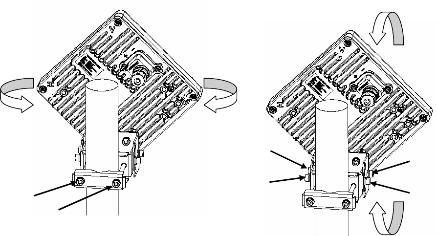
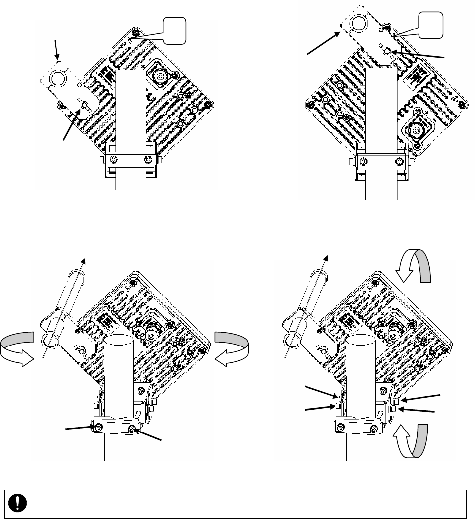
5.7.1.2. Roughly Adjusting the Direction
Step1 As shown in Figure 5-39, loosen the hexagonal socket head bolts (a) and (b) securing the
mounting bracket and swing the antenna left or right. Adjust the antenna approximately for
the WT direction and finger-tighten the bolts (a) and (b).
Step2 As shown in Figure 5-40, loosen the bolts (c), (d), (e) and (f) and tilt the antenna up or
down. Perform vertical-direction adjustment so that the WT of the opposite station can be
seen and finger-tighten the bolts (c), (d), (e) and (f).
Figure 5-35 Rough-adjusting Horizontal Direction Figure 5-36 Rough-Adjusting the Vertical Direction
垂直偏波
(a)
(b)
(d)
(c)
(e)
(f)
5-54
V
(a)
Direction adjustment tool
H
Direction adjustment tool
(a)
5.7.1.3. Roughly Adjusting the Direction (Using the Antenna direction adjustment tool)
Step1 As shown in Figure and Figure5-38, use the wing bolt (a) to attach the Antenna direction
adjustment tool.
Step2 As shown in Figure 5-39, loosen the hexagonal socket head bolts (b) and (c) securing the
mounting bracket and swing the antenna left or right. Adjust the antenna approximately for
the WT direction and finger-tighten the bolts (b) and (c).
Step3 As shown in Figure 5-40, loosen the bolts (d), (e), (f) and (g) and tilt the antenna up or
down. Perform vertical-direction adjustment so that the WT of the opposite station can be
seen through the scope of the Antenna direction adjustment tool.
.
Figure 5-37 How to Install Direction Adjustment tool
when the antenna type is the horizontal polarization
Figure5-38 How to Install Direction Adjustment tool
when the antenna type is the vertical polarization
In Figure 5-39 and Figure 5-40 is an example when the antenna type is the horizontal polarization.
Figure 5-39 Rough-adjusting Horizontal Direction Figure 5-40 Rough-Adjusting the Vertical Direction
・ Never look at the sun directly. Doing so may seriously damage the eyes.
(b)
(c)
(d)
(e)
(f)
(g)
5-55
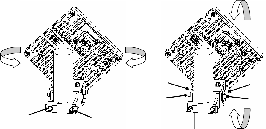
5.7.1.4. Finely Adjusting the Direction
Step 1: Horizontal direction
As shown in Figure 5-41, loosen the hexagonal socket head bolts (a) and (b) securing the
mounting bracket and swing the antenna left or right. Adjust the antenna direction so that the
receive level indicates the maximum value, and finger-tighten the bolts (a) and (b).
Step 2: Vertical direction
As shown in Figure 5-42, loosen the hexagonal socket head bolts (c), (d), (e) and (f) securing
the mounting bracket and tilt the antenna up or down. Adjust the antenna direction so that the
receive level indicates the maximum value. Tighten the bolts at a point showing the maximum
receive level (tightening torque: 8.5N•m).
Tighten the bolts in order of (f), (d), (e) and (c) and make sure that the point showing the
maximum receive level is maintained. This concludes the procedure for vertical-direction
adjustment.
Step 3: Horizontal direction
Finely adjust the horizontal direction by slightly loosening the bolts (a) and (b) again. Once
again, locate the point where the receiving level reaches the maximum value and hold that
point. Finally, tighten the bolts (a) and (b) (tightening torque: 8.5N•m) while making sure that
the point showing the maximum receiving level is maintained. This concludes the procedure
for horizontal-direction adjustment.
The figures show examples of horizontal polarization setup.
Figure 5-41 Finely Adjusting the Horizontal Direction Figure 5-42 Finely Adjusting the Vertical Direction
(a)
(b)
(d)
(c)
(e)
(f)

5-56
Note : When adjusting the antenna direction, you might mistakenly take the antenna's side
lobe as the maximum receive level. For fine adjustment, therefore, you should move the
antenna some more after the receiving level has reached the maximum value to make sure
that you have not caught a side lobe.
5-57
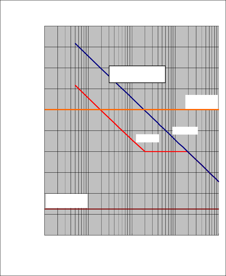
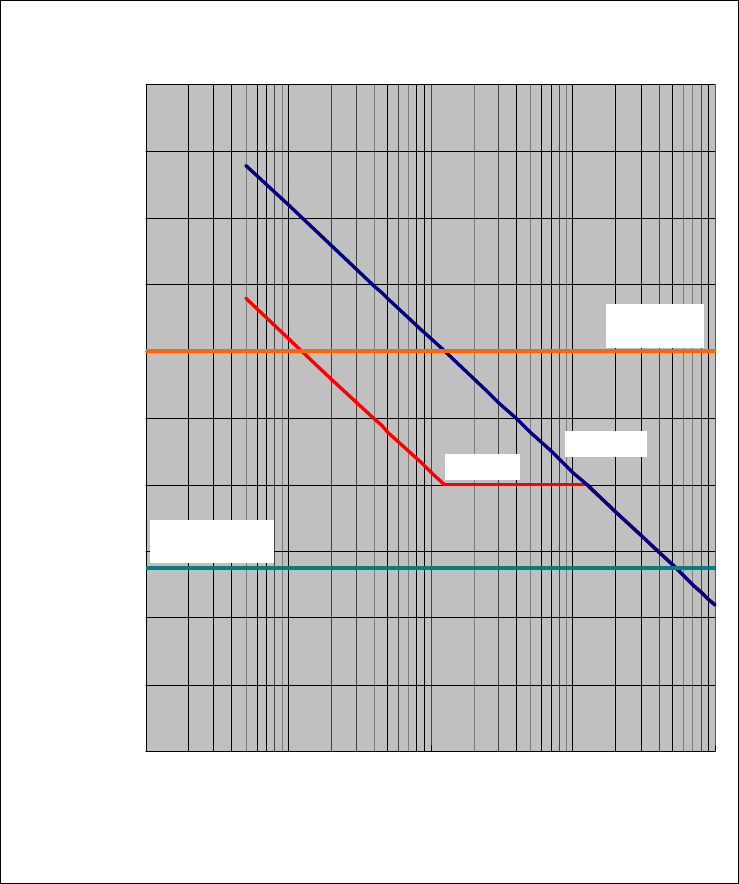
5.7.2. The receive level and the distance
In a point-to-point system, the receiving level at clear sky and the distance are related as shown as bellows
Receiving Level vs Distance
(SymbolRate:40MHz,QPSK)
ATPC ON ATPC OFF
Maximum
receiving level
Minimum receiving
level(QPSK)
-90.0
-80.0
-70.0
-60.0
-50.0
-40.0
-30.0
-20.0
-10.0
0.0
10.0
1 10 100 1000 10000
Distance [m]
Receiving Level [dBm]
Figure 5-43 Receiving Level and Distance (SymbolRate:40MHz,QPSK)
Receiving level
5-58
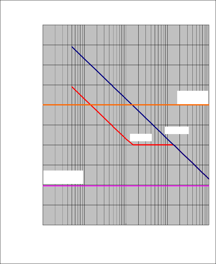
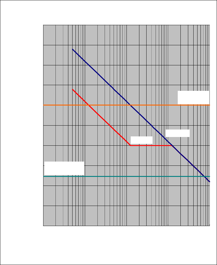
Receiving Level vs Distance
(SymbolRate:40MHz,16QAM)
ATPC ON ATPC OFF
Maximum
receiving level
Minimum receiving
level(16QAM)
-90.0
-80.0
-70.0
-60.0
-50.0
-40.0
-30.0
-20.0
-10.0
0.0
10.0
1 10 100 1000 10000
Distance [m]
Receiving Level [dBm]
Figure 5-44 Receiving Level and Distance (SymbolRate:40MHz,16QAM)
5-59
Receiving Level vs Distance
(SymbolRate:40MHz,64QAM)
ATPC ON ATPC OFF
Maximum
receiving level
Minimum receiving
level(64QAM)
-90.0
-80.0
-70.0
-60.0
-50.0
-40.0
-30.0
-20.0
-10.0
0.0
10.0
1 10 100 1000 10000
Distance [m]
Receiving Level [dBm]
Figure 5-45 Receiving Level and Distance (SymbolRate:40MHz,64QAM)
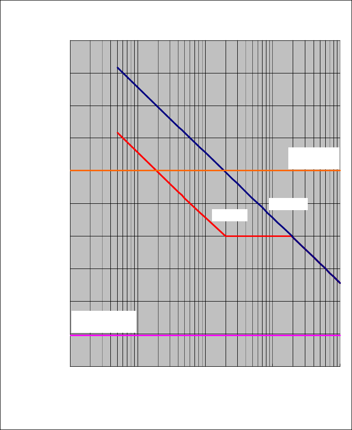
5-60
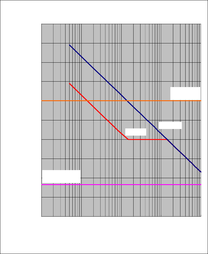
Receiving Level vs Distance
(SymbolRate:20MHz,QPSK)
ATPC ON ATPC OFF
Maximum
receiving level
Minimum receiving
level(QPSK)
-90.0
-80.0
-70.0
-60.0
-50.0
-40.0
-30.0
-20.0
-10.0
0.0
10.0
1 10 100 1000 10000
Distance [m]
Receiving Level [dBm]
Figure 5-46 Receiving Level and Distance (SymbolRate:20MHz,QPSK)
5-61
Receiving Level vs Distance
(SymbolRate:20MHz,16QAM)
ATPC ON ATPC OFF
Maximum
receiving level
Minimum receiving
level(16QAM)
-90.0
-80.0
-70.0
-60.0
-50.0
-40.0
-30.0
-20.0
-10.0
0.0
10.0
1 10 100 1000 10000
Distance [m]
Receiving Level [dBm]
Figure 5-47 Receiving Level and Distance (SymbolRate:20MHz,16QAM)
5-62
Receiving Level vs Distance
(SymbolRate:20MHz,64QAM)
ATPC ON ATPC OFF
Maximum
receiving level
Minimum receiving
level(64QAM)
-90.0
-80.0
-70.0
-60.0
-50.0
-40.0
-30.0
-20.0
-10.0
0.0
10.0
1 10 100 1000 10000
Distance [m]
Receiving Level [dBm]
Figure 5-48 Receiving Level and Distance (SymbolRate:20MHz,64QAM)
5-63
5.8. Installing the PoE PSE (master/slave)
PoE PSE (Power sourcing equipment) installed in indoor
It is an example of installing the PoE PSE.
About the installation of the PoE PSE, please install it according to the instruction manual of the
PoE PSE.
Figure 5-44 Installing the PoE PSE
On the plate
On the wall
5-64
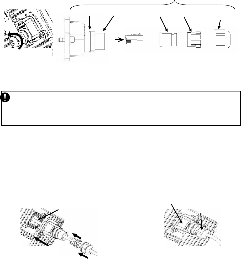
5.9. Connecting Cables to the WT (master/slave)
Connecting (1) Ethernet cable, (2) Ground wire and (3) Power supply
Figure 5-45 Connecting Cables to the WT
AC100V
User Terminal
WT
Vertical polarization
Horizontal polarization
FG Terminal
You will need a Torx
screwdriver (VESSEL
T20H-120) to open the
small
lid
of
the WT
Clamping Claw with Sealing Insert
Rubber
Ethernet Cable (Straight)
Thread-Lock Sealing Nut
Waterproofing
Small Lid
Body with Washer
(2) Ground wire
(1) Ethernet Cable
FG Terminal
M6 bolt (M6X12SUS)
Tool: Phillip screwdriver (No.3)
Tighten torque: 8.5N・m
(3) Power supply by PoE PSE

5-65
Remark *1: JRC doesn't offer PoE PSE. Please buy PoE PSE directly from PoE PSE bender.
(1) Ethernet Cable
Cable contents connect the WT and the PoE PSE
Interface 1000BASE-T, 100BASE-TX, 10BASE-T
Cable length Maximum 100m.
In case of PoE HUB use:100m is from the WT to PoE HUB
In case of PoE injector use: 100m is from the WT via PoE injector to
HUB. (Because, there is no function of terminate PHY in the PoE
injector)
Connector shape RJ-45
Pin assign - ETHER signal: MDI-X
- POWER: IEEE802.3at Type2
Cable type Ethernet cable for outdoor, STP(Shield Twisted Pair)
Range of applicable
outer diameter φ4.0 mm - 7.0mm
(2) Ground wire
Cable contents Connect the ground wire.
Applicable Cable Ground wire 1.6□ (AWG#14)
Applicable terminal FG terminal M6 nut.
Note ground resistance is 100 Ω or less
(3) power supply by PoE PSE
contents Power supply for The WT is supplied by PoE PSE (Power over
Ethernet Power Sourcing Equipment).
PoE specification - POWER: IEEE802.3at Type2
- Interface: 1000BASE-T
The PoE PSE which
confirmed connection
with the WT.
- PoE injector : PD-9001G-40/SP(Microsemi)*1
(The PD-9001G-40/SP provides also surge protection
functionality.)
Please connect a ground wire to FG terminal surely.
At the time of trouble and short circuit, It may cause the electric shock.
5-66
・Please do not use the Ethernet cable out of application cable diameter (φ 4.0mm to 7.0mm).
・Please do not take the body (d) and the washer (e) off the small lid. If you take it off, you must
tighten it by torque 1.2 to 1.5N / m completely.
5.10. Waterproofing WT Small lid
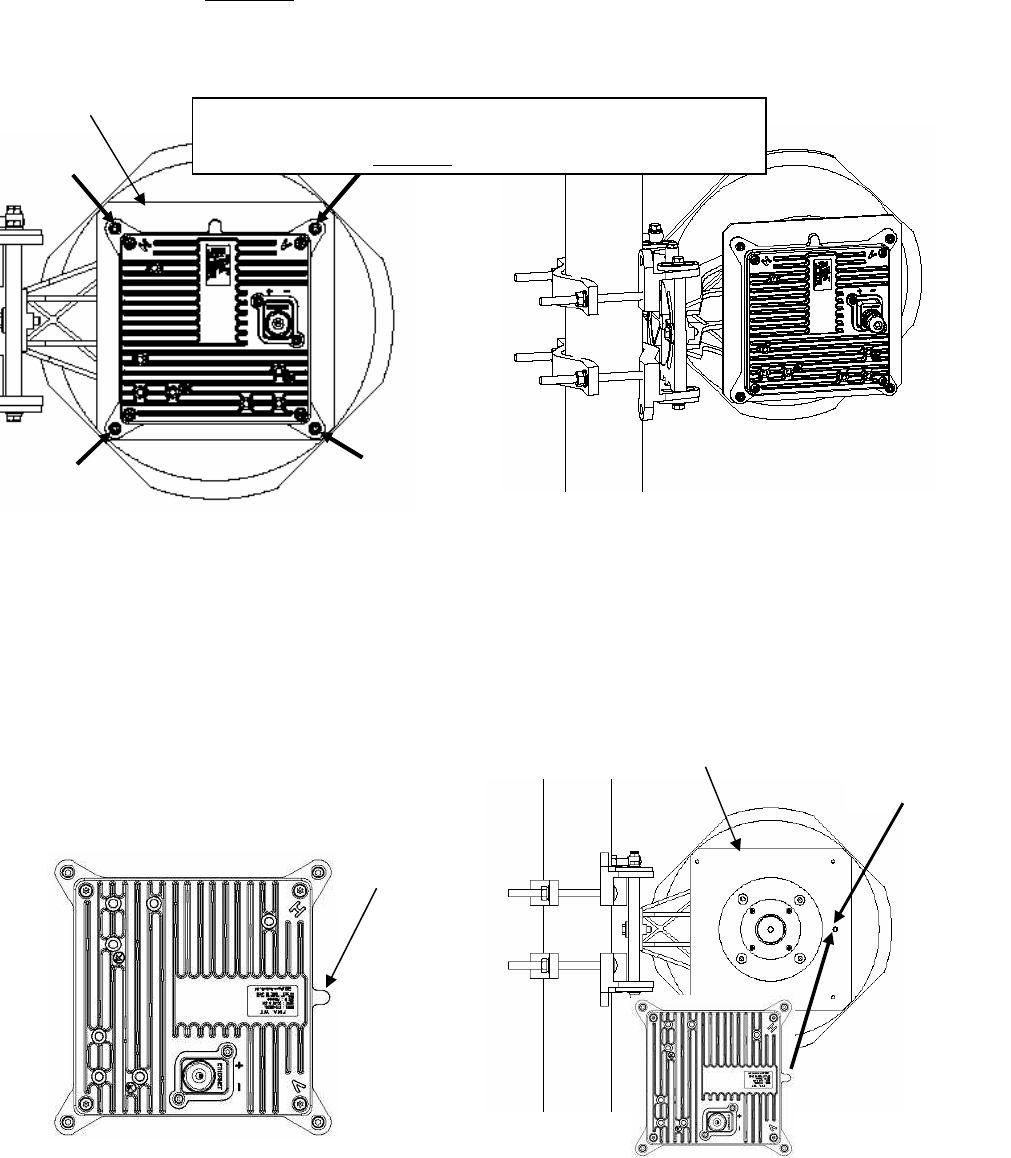
Step1 Loosen the sealing nut (a) and remove the sealing nut (a), Clamping Claw (b), Sealing
Insert (c) and insert Ethernet cable (f) and attach an Ethernet plug (please be careful about
insertion direction).
Please do not take the body (d) and the washer (e) off the Small lid (g).
Applicable LAN cable diameter: φ4.0 mm to 7.0mm
Step2 The Ethernet cable connects with the Ethernet connector of the WT after passing through
the Small lid (g) (with the body (d) and the Washer (e)). ( figure 2 31).
Fix the Small lid to the WT and fit Sealing Insert (c), Clamping Claw (b) and Sealing nut (a)
The sealing nut is tightened by torque 1.2 to 1.5N/m.
When tightening the sealing nut (a) by hand, you must completely tighten it.
When using a tool (box wrench, spanner), you must tighten up 90 degrees (a quarter turn) from
the point that felt tightening load
Figure 5-47 Figure 5-48
Figure 5-46
Take off a sealing nut
(d)Body
(e)Washer
(g)Small Lid
Waterproofing parts
(a) Sealing nut
(f) Ethernet Cable
(c)Sealing Insert、(b) Clamping Claw
Connect Ethernet plug
Recommended tightening torque: 1.2
to 1.5N/m
(g) Small window
Connect the Ethernet cable
(g) Small window
(a)Sealing nut
(b)Clamping Claw
(c)Sealing Insert
5-67
Step3 Fix the Ethernet cable to the pole by cable ties.
Bend the Ethernet cable and fix it appropriate so that does not take the load on the Ethernet
cable.
Figure 5-49
Step4 Wrap the self-bonding tape around the Small lid for waterproofing.
Using an appropriate length of self-bonding tape, wrap the tape around both the small Lid of
the WT (at its base) and spacer one complete turn (1). After one turn, wrap about some turns
around the Ethernet cable by overlapping one-half of the previous turn (2). Reverse the
wrapping direction and wrap about another some turns back to the small Lid (3).
Figure 5-50
The length more than 75mm
Cable ties
Does not take the load to the cable
(1) (2)
(3)
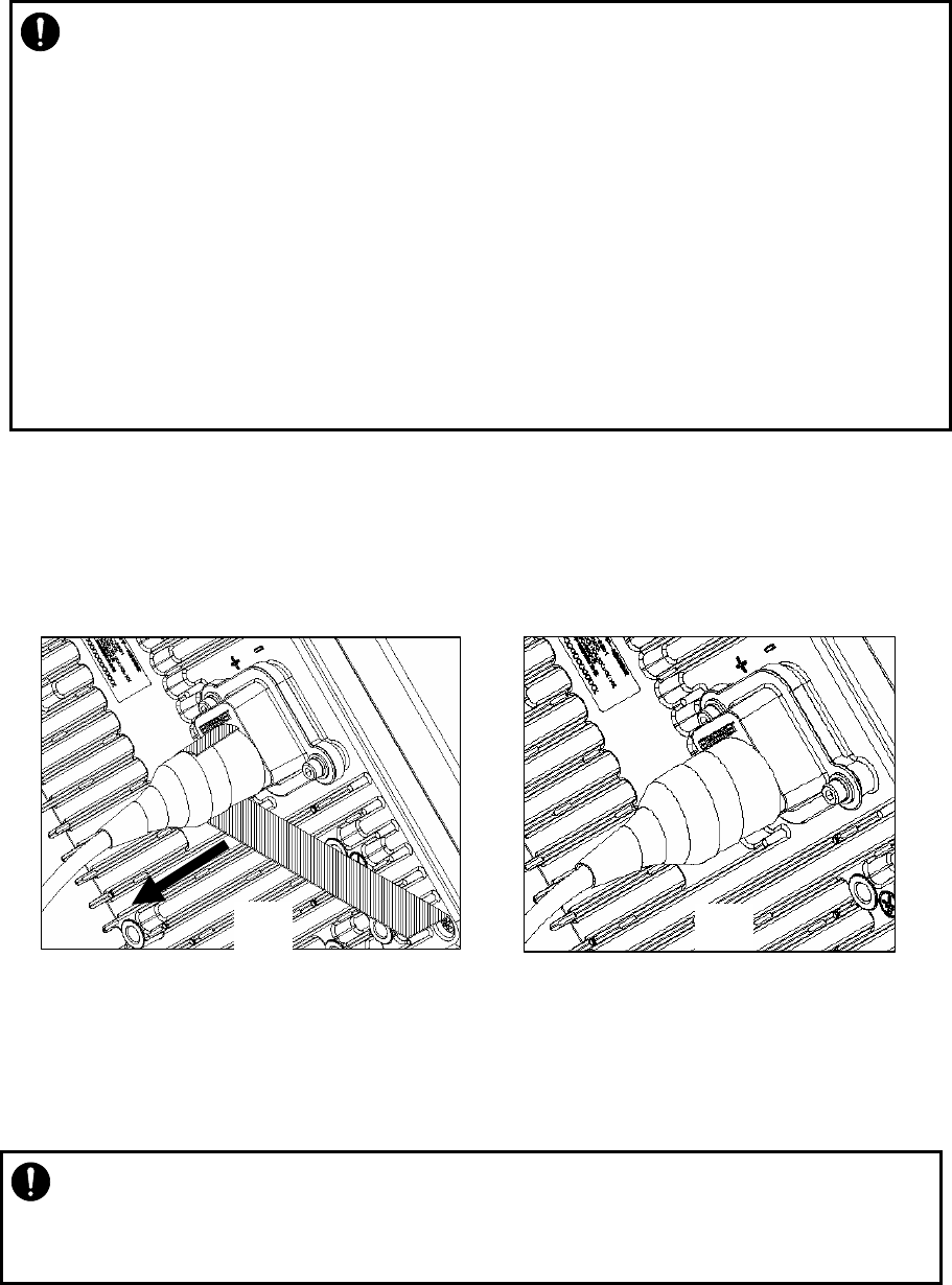
5-68
Step5 Wrap the PVC tape around the Small lid to protect it from ultraviolet rays.
Wrap the PVC tape so that the cold-shrinkable tube is completely hidden. Wrap the tape from
the small Lid of the WT to the Ethernet cable, overlapping half of the previous layer (1). Next,
reverse the wrapping direction and wrap one more time to the starting point (2).
Figure 5-51
・ For the stretching margin of self-bonding tape, see the instruction manual for the
product.
・ When wrapping self-bonding tape, start at the base of the small window and end at
the end of the waterproof sleeve. Next, reverse the direction and end at the base of
the small window. This procedure makes an attractive wrapping and improves the
waterproof effect by making any air pocketsless likely.
・ Overlapping the wraps also protects against air pockets.
・ Press evenly along the entire length of tape to remove air pockets.
・ Make sure that there are no air pockets between the self-bonding tape and the small
window of the WT or the waterproofing parts. Air pockets will degrade the
waterproofing effect.
・ Please never get the small lid inside wet with water. It causes the trouble.
・ Please fix the each part of the waterproofing parts to small lid without a missing part.
It cause of poor waterproofing.
(1) (2)
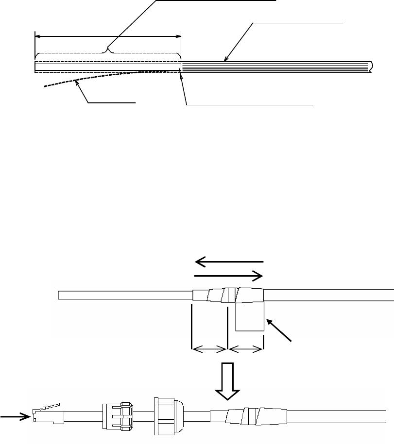
5-69
25 25 Self-bonding
Push The Ethernet plug
5.11. When you use the cable with the LAP sheath for outdoor
Step1.Processing of LAP sheath
- The LPA sheath is peeled off from the cable point to 120mm.
- It cuts it in the part peeled off when there is drain wire.
Step2.Processing of cutting part
- To prevent water being infiltrated in the wire, the self-bonding tape is rolled in the part
where the LAP sheath was peeled off as shown in the figure below.
- The Ether plug is installed with the thread-lock sealing nut, the clamping claw and the
sealing insert passed.
120mm
The cable with the LAP sheath
Drain
wire
is cut on the LAP sheath side.
Drain Wire
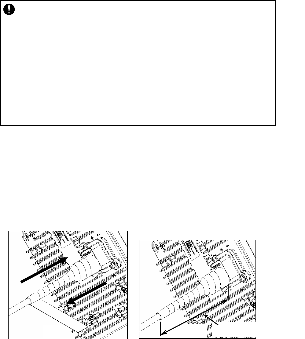
5-70
Step3.Fixation of cable Ethernet、Installation of waterproofing parts.
See「5.10Waterproofing WT Small lid」
Step4 Wrap the self-bonding tape around the Small lid for waterproofing.
Using an appropriate length of self-bonding tape, wrap the tape around both the small Lid of
the WT (at its base) and spacer one complete turn. After one turn, wrap about some turns
around the Ethernet cable by overlapping one-half of the previous turn (1). Reverse the
wrapping direction and wrap about another some turns back to the small Lid (2).
Figure 5-52
Step5 Wrap the PVC tape around the Small lid to protect it from ultraviolet rays.
Wrap the PVC tape so that the cold-shrinkable tube is completely hidden. Wrap the tape from
the small Lid of the WT to the Ethernet cable, overlapping half of the previous layer (1). Next,
reverse the wrapping direction and wrap one more time to the starting point (2).
・ For the stretching margin of self-bonding tape, see the instruction manual for the
product.
・ When wrapping self-bonding tape, start at the base of the small window and end at
the end of the waterproof sleeve. Next, reverse the direction and end at the base of
the small window. This procedure makes an attractive wrapping and improves the
waterproof effect by making any air pocketsless likely.
・ Overlapping the wraps also protects against air pockets.
・ Press evenly along the entire length of tape to remove air pockets.
・ Make sure that there are no air pockets between the self-bonding tape and the small
window of the WT or the waterproofing parts. Air pockets will degrade the
waterproofing effect.
The length more than 120mm
(1) (2)
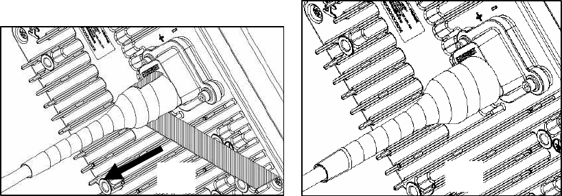
5-71
Figure 5-53
(1) (2)
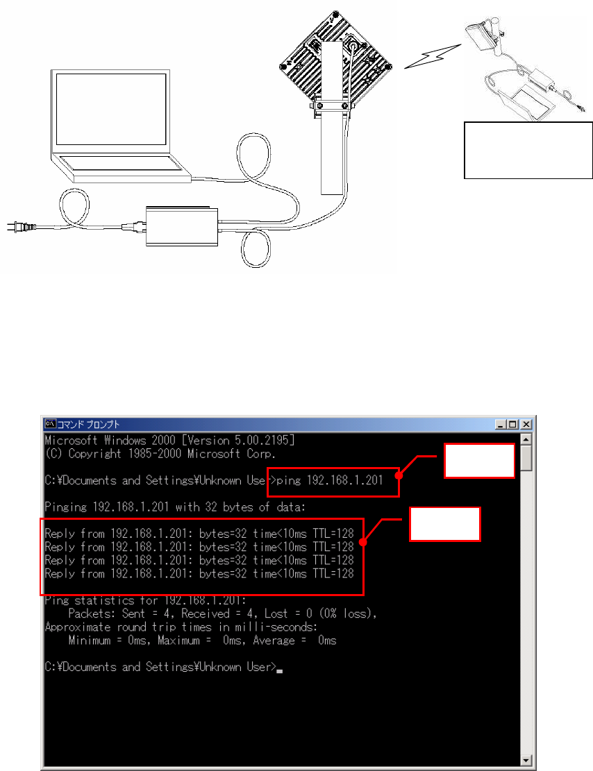
5-72
5.12. Testing
5.12.1. Ping test
Connect the WT and the PC as shown in Figure 5-54. Use the PC to perform a ping test in the
following procedure.
Figure 5-54 Ping Test System Diagram
Step 1: Start the Windows command prompt.
Step 2: Type the following command and press the Return key.
Ping xxx.xxx.xxx.xxx, where xxx.xxx.xxx.xxx shows the IP address of the
opposite PC.
Step 3: After the command is run, check that a reply as shown in Figure 5-55 returns.
Figure 5-55 Ping Test
Master
PC
192.168.1.200
Ethernet Cable
(Straight)
PoE PSE
Ethernet Cable (Straight)
Slave
Step 2
Step 3
PC
192.168.1.201
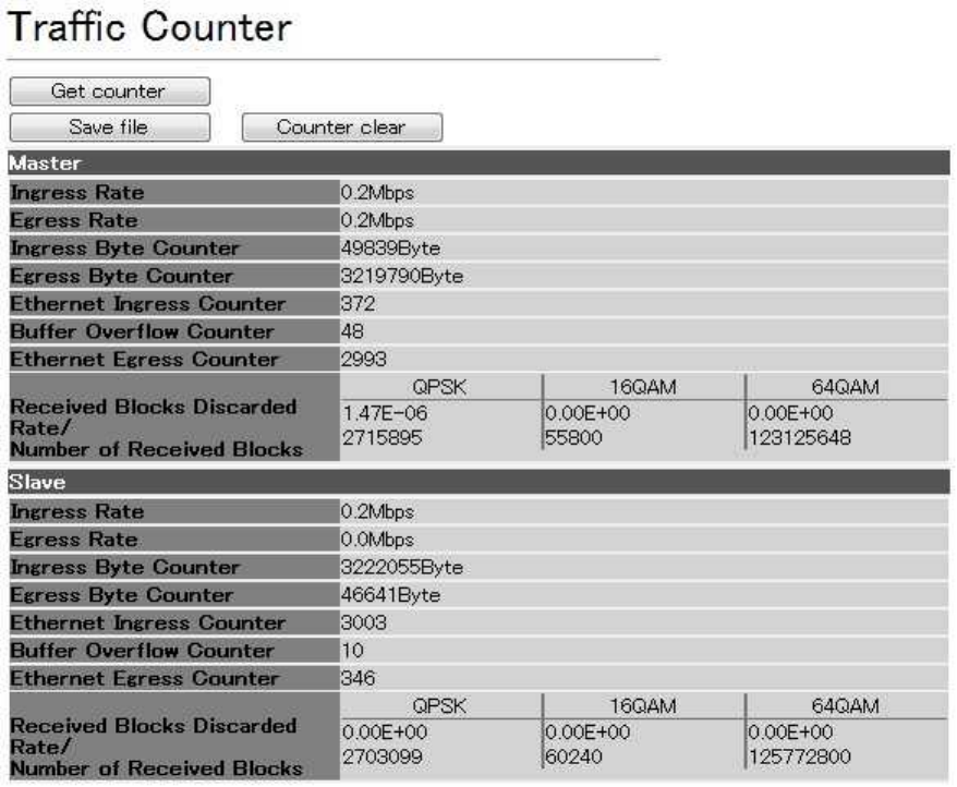
5-73
5.12.2. Measure the Received Blocks Discarded Rate
Connect the Management Tool and measure the Received Blocks Discarded Rate in the following
procedure:
Step 1: Start the Management Tool (Login Class: admin, operator, monitor).
Step 2: Select Monitoring > Traffic Counter tab.
Step 3: Click the Counter Clear button to start traffic measurement after counter reset.
Step 4: After traffic measurement for any length of time, Click the Get counter button to
display the traffic measurement result.
Step 5: Check “Received Blocks Discarded Rate."
Figure 5-56 Measure the Received Blocks Discarded Rate

5-74
5.13. Check sheet
Check operation of the WT (Master/Slave) using the check sheet below.
Table 5-2 Check sheet
WT Serial number Test date
Test type Test condition Check item Pass/fail
Measured value
Check the Cable
between WT and
PoE
Maintenance
Tool
Connect the Management Tool to the WT and confirm
that login is possible normally.
Receive level Maintenance
Tool
Connect the Management Tool to the WT and measure
the receive level. dBm
measure the
Received Blocks
Discarded Rate
Maintenance
Tool
Connect the Management Tool to the WT and measure
the Received Blocks Discarded Rate
Ping TEST PC Check the reply from opposite PC. -

6-75
6. Standard Tools for installation
The table below lists the tools used during installation or maintenance of the units.
Table 6-1 Tools Used
No.
Unit
name Used for: Tightening
torque [N•cm]
Tool
1 Small lid M4 127 Torx driver (VESSEL T20H-120)
2 Mounting bracket M6 850 Allen wrench (Width across flats: 5)
3 FG Terminal M6 850 #2 phillips screwdriver
4
WT
Ethernet cable Crimping tool for RJ-45
(Release-after-crimp type)
The appropriate tightening torque is 10% of the value indicated in the table.

7-76
7. INITIAL VALUES
7.1.1. Initial values for WT(Master) parameters (Point to point System)
Table 7-1 lists the WT defaults set in the factory.
No. Parameters 1 Parameters 2 Initial values
QoS and Traffic Control
12 Class 7 1000 [KB]
13 Class 6 1000 [KB]
14 Class 5 1000 [KB]
15 Class 4 1000 [KB]
16 Class 3 1000 [KB]
17 Class 2 1000 [KB]
18 Class 1 1000 [KB]
19
Buffer Size Configuration
(Master)
Class 0 1000 [KB]
20 Class 7 1000 [KB]
21 Class 6 1000 [KB]
22 Class 5 1000 [KB]
23 Class 4 1000 [KB]
24 Class 3 1000 [KB]
25 Class 2 1000 [KB]
26 Class 1 1000 [KB]
27
Buffer Size Configuration
(Slave)
Class 0 1000 [KB]
28
COS assignment for
Management
Communication from
Master to Slave
7
29 Class 7 In Service
30 Class 6 In Service
31 Class 5 In Service
32 Class 4 In Service
33 Class 3 In Service
34 Class 2 In Service
35 Class 1 In Service
36
QoS Priority Class
Configuration(Master)
Class 0 In Service

7-77
No. Parameters 1 Parameters 2 Initial values
37 Class 7 In Service
38 Class 6 In Service
39 Class 5 In Service
40 Class 4 In Service
41 Class 3 In Service
42 Class 2 In Service
43 Class 1 In Service
44
QoS Priority Class
Configuration(Slave)
Class 0 In Service
45 Dynamic TDD Fixed
46 DL /UL Ratio DL Ratio 50 [%]
47 COS 値7 7
48 COS 値6 0
49 COS 値5 0
50 COS 値4 0
51 COS 値3 0
52 COS 値2 0
53 COS 値1 0
54
COS [0-7] vs. Priority
Class [0-7]("7"is the
highest Priority) Table
COS 値0 0
55 IP Precedense
56
Master
TOS vs. COS [0-7] Table
7∼0 0
57 DSCP
58
Master
TC [0-255] vs. COS [0-7]
Table 63∼0 0
59 except following EtherTypes
0
60
Master
EtherType vs. COS [0-7]
Table 15 setting items Not set
61 IP Precedense
62
Slave
Slave
TOS vs. COS [0-7] Table
7∼0 0
63 DSCP
64
Slave
TC [0-255] vs. COS [0-7]
Table 63∼0 0
65 except following EtherTypes
0
66
Slave
EtherType vs. COS [0-7]
Table 15 setting items Not set
67 Class7∼0(QPSK)
68 Class7∼0(16QAM)
69
Policing Rate(Master)
Class7∼0(64QAM)
0[Mbps]
70 Class7∼0(QPSK)
71 Class7∼0(16QAM)
72
Policing Rate(Slave)
Class7∼0(64QAM)
0[Mbps]

7-78
No. Parameters 1 Parameters 2 Initial values
73 Class7∼0(QPSK)
74 Class7∼0(16QAM)
75
Shaping Rate(Master)
Class7∼0(64QAM)
0[Mbps]
76 Class7∼0(QPSK)
77 Class7∼0(16QAM)
78
Shaping Rate(Slave)
Class7∼0(64QAM)
0[Mbps]
Configuration (Radio)
79 Operating Mode P-P(Master)
80 Symbol Rate 40.0 [MHz]
81 Frame ID Number 1
82 Encryption Parameter 1234567890
83 Maximum Service
Distance 7 [km]
84 MTPC Transmitted Level 5.0 [dBm]
85 ATPC Enable
86
ATPC
87 Network Element Name Not set
88 Scanning CH Range 4∼42[CH]
89
90 Modulation
91 DL Modulation Scheme 64QAM
92
Modulation
UL Modulation Scheme 64QAM
93 Master Enable
94 RF Transmission Slave Enable
Configuration (Network)
95 IPaddress 192.168.1.100
96 Subnet mask 255.255.255.0
97
IPv4
Default gateway Not set
98 Disable
99 IPaddress Not set
100
IPv6
Default gateway Not set
101
Ethernet configuration 1000BASE-T(AUTO)
102
Disable
103
VID 0
104
Management VLAN TAG
(No.1) COS 0
105
Disable
106
VID 0
107
Management VLAN TAG
(No.2) COS 0
108
Disable
109
VID 0
110
Management VLAN TAG
(No.3) COS 0
111
Disable
121
<SNMP>
OpS1 IPv4 0.0.0.0

7-79
No. Parameters 1 Parameters 2 Initial values
113
IPv6 Not set
114
Disable
115
IPv4 0.0.0.0
116
<SNMP>
OpS2 IPv6 Not set
117
Disable
118
IPv4 0.0.0.0
119
<SNMP>
OpS3 IPv6 Not set
120
Get Community Name 1 Public
121
Set Community Name 1 Public
122
Get Community Name 2 Public2
123
Set Community Name 2 Public2
124
Get Community Name 3 Public3
125
<SNMP>
Community Name (SNMP
v2)
Set Community Name 3 Public3
126
User Name username1
127
Authentication protocol MD5
128
Authentication Password 000000000000000
129
Encryption protocol AES
130
Encryption Password 000000000000000
131
<SNMP>
User Name (SNMP
v3)(User1)
Accsess Control Read Only
132
User Name username2
133
Authentication protocol MD5
134
Authentication Password 000000000000000
135
Encryption protocol AES
136
Encryption Password 000000000000000
137
<SNMP>
User Name (SNMP
v3)(User2)
Accsess Control Read Only
138
User Name username3
139
Authentication protocol MD5
140
Authentication protocol 000000000000000
141
Encryption protocol AES
142
Encryption Password 000000000000000
143
<SNMP>
User Name (SNMP
v3)(User3)
Accsess Control Read Only
144
Disable
145
IPv4 0.0.0.0
146
IPv6 Not set
147
SNMP Version SNMPv2
148
SNMPv2 Community Name Public
149
SNMPv3 User Name username
150
Authentication protocol MD5
151
Authentication protocol 000000000000000
152
Encryption protocol AES
153
<SNMP>
Trap destination 1
Encryption Password 000000000000000

7-80
No. Parameters 1 Parameters 2 Initial values
154
Disable
155
IPv4 0.0.0.0
156
IPv6 Not set
157
SNMP Version SNMPv2
158
SNMPv2 Community Name public2
159
SNMPv3 User Name username2
160
Authentication protocol MD5
161
Authentication protocol 000000000000000
162
Encryption protocol AES
163
<SNMP>
Trap destination 2
Encryption Password 000000000000000
Configuration (Boot Sector Selection )
164
Master Boot Sector Select bank A/B after reset Bank A
Slave Boot Sector Select bank A/B after reset Bank A
Configuration (Date and Time)
165
Date and Time 2000/00/00 00:00:00
166
Clock Setting Mode PC time
167
IPv4 Not set
168
IPv6 Not set
169
Host Not set
170
IPv4(DNS Server)Primary
0.0.0.0
171
IPv4 (DNS Server )
Secondary 0.0.0.0
172
IPv6(DNS Server)Primary
Not set
173
NTP Server
IPv6 (DNS Server )
Secondary Not set
174
The Time zone Name UTC-04:30
Set summer time
( + 1 hour ) Not set
Configuration (Login class password)
175
Admin admin1234
176
Installation inst1234
177
Operator ope1234
178
Login Class
password
Monitor moni1234

7-81
7.1.2. Initial values for WT (Slave) parameters (Point to point
System)
Table 7-2 lists the WT (Slave) defaults set in the factory.
No. Parameters 1 Parameters 2 Initial values
Traffic Control
12
COS assignment for
Management
Communication from
Master to Slave
7
Configuration (Radio)
20 Operating Mode P-P(Master)
21 Symbol Rate 40.0 [MHz]
22 Frame ID Number 1
23 Encryption Parameter 1234567890
24 MTPC MTPC Transmitted Level 5.0 [dBm]
25 Network Element Name Not set
Configuration (Network)
27 IPaddress 192.168.1.100
28 Subnet mask 255.255.255.0
29
IPv4
Default gateway Not set
30 Disable
31 IPaddress Not set
32
IPv6
Default gateway Not set
33 Ethernet configuration 1000BASE-T(AUTO)
34 Disable
35 VID 0
36
Management VLAN TAG
(No.1) COS 0
37 Disable
38 VID 0
39
Management VLAN TAG
(No.2) COS 0
40 Disable
41 VID 0
42
Management VLAN TAG
(No.3) COS 0
Configuration (Login class password)
45 Admin admin1234
46 Installation inst1234
47 Operator ope1234
48
Login Class
password
Monitor moni1234

9-82
8. Revision History
Version Date Description
Ver1.0 13/Nove./2011 first edition
Ver1.1 26/Dec./2011 - Page 3-22 and Page 5-58, pin assign :change from MDI to MDI-X
(Error correction for Typo)
- Page 3-22 and Page 5-58, Cable type : addition “STP(Shield
Twisted Pair)”, (Error correction for Typo)
- Page 2-9 , Change Minimum receiving level (Error correction for
Typo)
- Page 5-25, Table 8-1: addition the Pole
- Figure 5-43 to 48, delete it, because there were the same figures.
Ver1.2 26/Mar./2012 -Page 2-9 Transmit output power 16QAM and 64QAM (Error
correction for Typo)
-Page 1-5 1.2CERTIFICATION NOTE FROM INDUSTRY
CANADA: addition French explanation and Error correction for
Typo
- Page 2-12, Add nameplate(b) for CE mark
- Page 1-5, Add 1.3.Required by RSS-191, clause 5.1(a)
- Page 1-5, Add 1.4.For Europe (R&TTE)
Ver1.3 20/Apr/2012 -Page 1-6, Add 1.5. Declaration of Conformity (DoC)
9. Others
- Ethernet is a registered trademark of XEROX Corporation.

9-83
 ̄ ̄ ̄ ̄ ̄ ̄ ̄ ̄ ̄ ̄ ̄ ̄ ̄ ̄ ̄ ̄ ̄ ̄ ̄ ̄ ̄ ̄ ̄ ̄
WIPAS2
Instruction Manual
H-7YZCM5107B
Rev. 1.3
20/Apr./2012
 ̄ ̄ ̄ ̄ ̄ ̄ ̄ ̄ ̄ ̄ ̄ ̄ ̄ ̄ ̄ ̄ ̄ ̄ ̄ ̄ ̄ ̄ ̄ ̄