Johnson Outdoors WFTA Controller User Manual 237 7120
Johnson Outdoors, Inc. Controller 237 7120
Manual
www.minnkotamotors.com
P/N 2377122 REV. A 7-06
NOTE: Do not return your Minn Kota CoPilot to your
retailer. Your retailer is not authorized to repair or
replace this unit. You may obtain service by calling Minn
Kota at 1-800-227-6433 or 1-507-345-4623 or returning
your CoPilot, in the original package, to the Minn Kota
Factory Service Center.
Please include proof of purchase, serial number and
purchase date for warranty service.
Serial Number CP
Nº de série
Purchase Date
Date d’achat
CAUTION: READ THIS MANUAL
CAREFULLY BEFORE OPERATING YOUR
NEW MINN KOTA COPILOT.RETAIN
FOR FUTURE REFERENCE.SYSTEM COMPONENTS
SYSTEM FEATURES
INSTALLING THE CO-PILOT
ADDING/REMOVING
REMOTES
MISCELLANEOUS INFORMATION
BATTERY REPLACEMENT
GENERAL OPERATION
AUDIO MODES
TROUBLESHOOTING
TECHNICAL ASSISTANCE
FAQ’s
FCC DISCLAIMER/LICENSE
WARRANTY INFORMATION
pg.2
pg.3
pg.4-6
pg.6-7
pg.7
pg.8-9
pg.9-10
pg.10-12
pg.13
pg.14
pg.14
pg.15
pg.16
REMARQUE : Ne renvoyez pas votre copilote Minn
Kota à votre détaillant. Votre détaillant n’est pas autorisé
àréparer ou remplacer cette unité. Vous pouvez obtenir
de l’aide en appelant Minn Kota au 1-800-227-6433 ou
1-507-345-4623 (numéros américains) ou en renvoyant
votre copilote, dans son emballage d’origine, au Centre
de service en usine Minn Kota. Veuillez inclure la preuve
d’achat, le numéro de série et la date d’achat pour le
service sous garantie.
PRÉCAUTION : LISEZ ATTENTIVE-
MENT CE MANUEL AVANT D’UTILISER
VOTRE NOUVEAU COPILOTE MINN
KOTA. GARDEZ CE LIVRET POUR
VOUS Y REPORTER À L’AVENIR.
PATENT 5,859,517
COMPOSANTS DU SYSTÈME
PARTICULARITÉS DU SYSTÈME
INSTALLATION DU COPILOTE
AJOUTER/ENLEVER LES COMMANDES
ÀDISTANCE
INFORMATION DIVERSE
REMPLACEMENT DE LA BATTERIE
FONCTIONNEMENT GÉNÉRAL
MODES AUDIO
DÉPANNAGE
ASSISTANCE TECHNIQUE
QUESTIONS FRÉQUEMMENT POSÉES
RENONCIATION DU FCC/LICENSE
INFORMATION SUR LA GARANTIE
OR
Copilot Wireless foot pedal system
Limited Warranty:
Johnson Outdoors Inc.- MINN KOTA warrants to the original
purchaser that its MINN KOTA CoPilot is free from defects in
materials or workmanship for a period of two ( 2 ) years from
the date of purchase, except that this warranty shall not apply
to any product used commercially. The unit must be returned,
prepaid and with proof of the date of purchase and serial num-
ber to the following:
• MINN KOTA Factory Service Center, 706 Holly Lane,
Mankato, MN 56001-8129, USA
NOTE: Do not return your MINN KOTA CoPilot or parts to your
retailer.Your retailer is not authorized to repair or replace this
unit.
If after inspection, we find that the product was defective in
material or workmanship, we shall, at our option, repair or
replace it without charge. We are not responsible for normal
wear and tear or for defects caused by accidents, abuse, alter-
ation, modification, misuse or improper care.
There are no other express warranties beyond the terms
of this limited warranty. In no event shall any implied war-
ranties, including merchantability and fitness for a partic-
ular purpose, extend beyond the duration of the express
warranty contained herein. In no event shall Johnson
Outdoors Inc.- MINN KOTA, be liable for incidental or con-
sequential damages.
Some states do not allow limitations on how long an implied
warranty lasts or the exclusion of limitation of incidental or con-
sequential damages, so the above limitations or exclusions
may not apply to you. This warranty gives you specific rights
and you may have other rights which vary from state to state.
Information regarding this warranty performance may be
obtained by contacting MINN KOTA at:
1-800-227-6433 or
FAX at 1-800-527-4464
“WARNING: This product contains chemical(s) known to the
state of California to cause cancer and/or reproductive toxicity.
Garantie limitée :
Johnson Outdoors Inc.- MINN KOTA garantit à l’acheteur d’ori-
gine que son copilote MINN KOTA sera exempt de défaut de
matériaux ou de main d’œuvre pendant une période de deux
(2)ans à partir de la date d’achat ; cette garantie exclut les
produits utilisés commercialement. L’unité doit être renvoyée,
fret prépayé avec preuve d’achat, date d’achat et numéro de
série à l’adresse suivante :
• MINN KOTA Factory Service Center, 706 Holly Lane,
Mankato, MN 56001-8129, USA
REMARQUE : Ne renvoyez pas votre copilote ou pièces
MINN KOTA à votre détaillant. Votre détaillant n’est pas auto-
risé à réparer ou remplacer cette unité.
Si après inspection, nous découvrons que le produit est défec-
tueux en matériaux ou main d’œuvre, nous, selon notre choix,
le réparerons ou le remplacerons sans frais. Nous ne sommes
pas responsables de l’usure normale ou des défauts causés
par des accidents, l’abus, les modifications, le mauvais emploi
ou les mauvais soins.
Il n’existe pas de garanties exprimées autres que celle
établie par les termes de cette garantie limitée. En aucun
cas, une garantie implicite, y compris l’aptitude à être
vendu ou à convenir à un but particulier, n’est valide au-
delà de la durée de la garantie exprimée ici. En aucun cas,
Johnson Outdoors Inc. – MINN KOTA ne pourra être tenue
responsable des dégâts accidentels ou conséquents.
Quelques états ne permettent pas de limites sur la durée des
garanties implicites ou sur l’exclusion ou la limitation des
dégâts accidentels ou conséquents, donc il se peut que les
limitations ou exclusions ci-dessus ne s’appliquent pas à vous.
Cette garantie vous procure des droits légaux spécifiques et
vous pouvez aussi avoir d’autres droits qui varient d’un état à
l’autre.
L’information au sujet de la performance de cette garantie peut
être obtenue en prenant contact avec MINN KOTA au :
1-800-227-6433 ou par télécopie au :
1-800-527-4464 (USA)
Wireless main remote and rodmounts included in 1866150 kit only.
La radio lointaine et les monts de baguette inclus dans 1866150 kit seulement
Wireless foot pedal included in 1866060 kit only.
La pédale de pied sans fil incluse dans 1866060 kit seulement
215
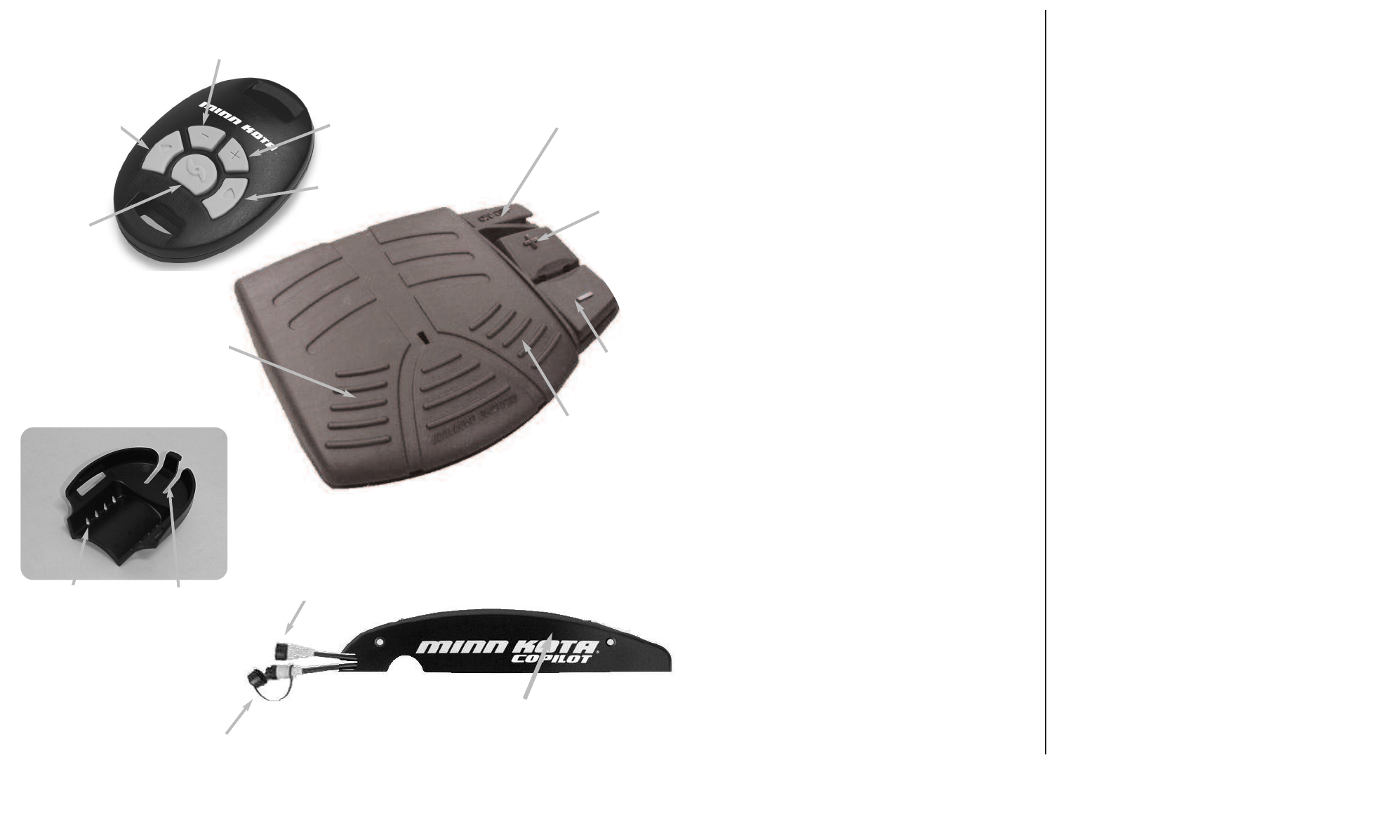
Steer Left
Tourner à
gauche
Prop ON/OFF
Mise EN
MARCHE/À
L’ARRÊT de
l’hélice
Steer Right
Tourner à
droite
Increase Speed
Accélérer
Decrease Speed
Décélérer
Learn Button
Bouton informant
Corded Footpedal Plug
Fiche de la pédale
Trolling Motor Plug
Fiche du moteur de
pêche à la traîne
COPILOT RECEIVER
RÉCEPTEUR DU COPILOTE
COPILOT REMOTES
COMMANDE À DISTANCE DU COPILOTES
SYSTEM COMPONENTS
COMPOSANTS DU SYSTÈME
ROD MOUNT FOR HAND REMOTE
MONTANT DE CANNE LES MAIN LOINTAINE
Mounting Holes
Trous de montage Locking Latch
Loquet de
verrouillage
Prop ON/OFF
Mise EN
MARCHE/À
L’ARRÊT de
l’hélice
Increase Speed
Accélérer
Decrease Speed
Décélérer
Steer Right
Tourner à
droite
Steer Left
Tourner à
gauche
FCC DISCLAIMER
Compliance Statement ( Part 15.19 )
This device complies with Part 15 of the FCC Rules and with
RSS-210 of Industry Canada. Operation is subject to the fol-
lowing two conditions:
1. This device may not cause harmful interference, and
2. This device must accept any interference received, includ-
ing interference that may cause undesired operation.
Warning ( Part 15.21 )
Changes or modifications not expressly approved by the
party responsible for compliance could void the user’s
authority to operate the equipment.
Industry Canada Statement
The term “IC” before the certification/registration number
only signifies that the Industry Canada technical specifica-
tions were met.
LIMITED LICENSE
The CoPilot Wireless Remote System contained herewith includes
atransmitter remote, a receiver,and one or more mounting brack-
ets. This CoPilot System is protected by U.S. Patent No. 5,859,517
and copyrights in the United States and other countries. Your use
to this Copilot System is limited by patent and copyright laws, and is
authorized according to the following terms and conditions.
You are authorized to: (1) use the CoPilot System as contained in
this package; (2) use the CoPilot System with extra or supplemental
transmitter remotes, receivers, or mounting brackets that are
designed to work with this CoPilot System and is either sold by
Minn Kota or sold with the permission of Minn Kota; and (3) transfer
the CoPilot System and license to another party if the other party
agrees to accept the terms and conditions of this license.
You are not authorized to: (1) use the CoPilot System with extra or
supplemental transmitters, receivers, and/or mounting brackets
manufactured by companies other than Minn Kota or not authorized
by Minn Kota; or (2) use, copy, modify, reverse engineer, or transfer
any CoPilot System software except as expressly provided for in
this license.
The license is effective until terminated. You may terminate it at any
time by destroying the CoPilot System. The license will also termi-
nate if you fail to comply with any term or condition of this
Agreement.
You may not sublicense, assign or transfer the license or the
CoPilot System software except as expressly provided in this
license. Any attempt otherwise to sublicense, assign or transfer any
of the rights, duties, or obligations is void.
Any unauthorized use of the Copilot System will void any warranty.
Should you have any questions concerning this license, you may
contact Minn Kota by writing to Minn Kota, Inc., 1531 E. Madison
Ave, P.O. Box 8129, Mankato, MN 56002-8129.
RENONCIATION DU FCC
Déclaration d’adhérence ( Partie 15.19 )
Cet appareil respecte la partie 15 des règlements du
conseil fédéral de l’audiovisuel aux États-Unis (FCC)
et la norme RSS-210 de l’industrie canadienne. Son
utilisation est sujette aux deux conditions suivantes :
1. Cet appareil ne doit pas causer d’interférences
nocives.
2. Cet appareil doit supporter toutes les interférences
reçues, y compris les interférences pouvant causer un
fonctionnement non désiré.
Avertissement ( Partie 15.21 )
Les changements ou modifications n’étant pas
expressément approuvées par la partie chargée de
l’adhérence aux normes pourraient annuler l’autorité
de l’utilisateur à employer cet équipement.
Déclaration de l’industrie canadienne
Le terme « IC » avant le numéro de
certification/enregistrement signifie seulement que les
spécifications techniques de l’industrie canadienne
furent respectées.
HAND REMOTE
MAIN LOINTAINE
WIRELESS PEDAL
PÉDALE SANS FIL
3
14
SYSTEM FEATURES
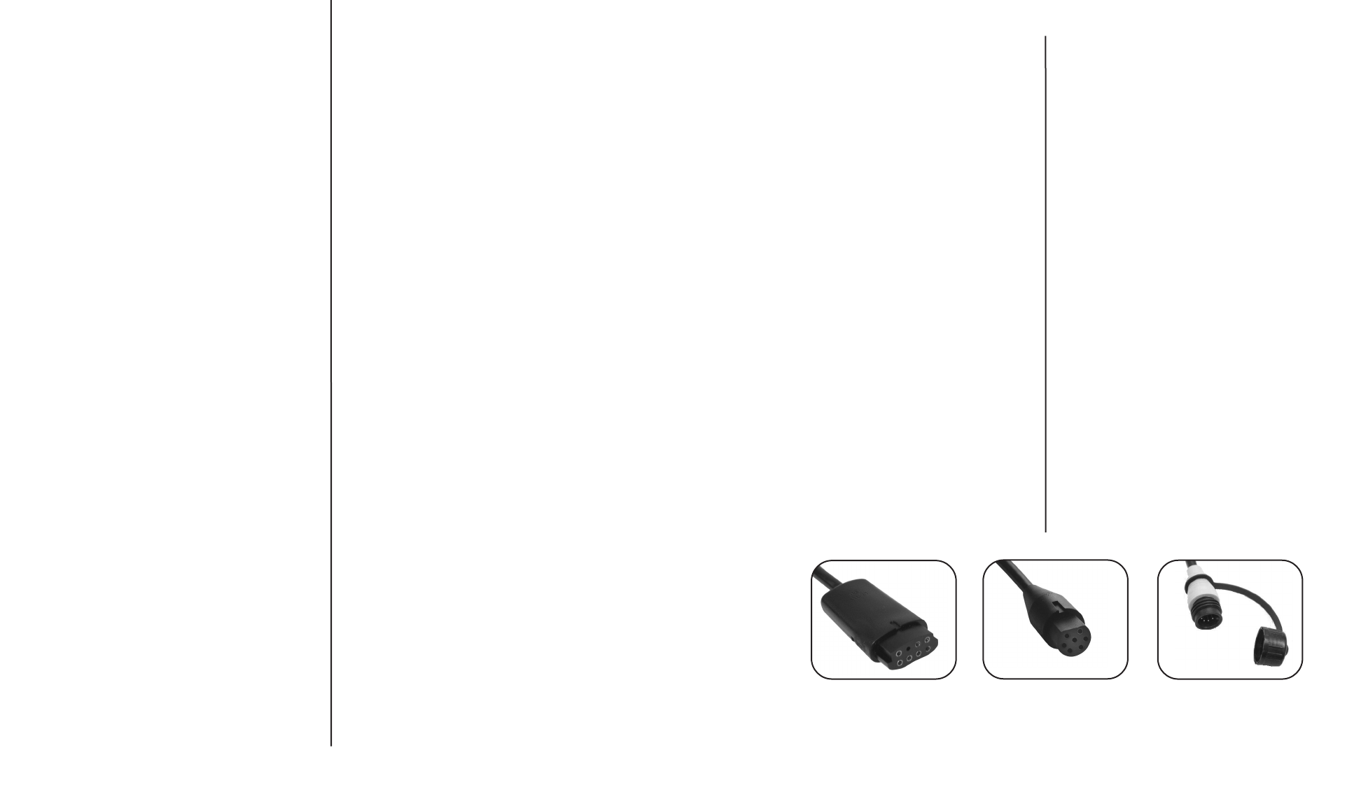
•Wireless control for corded PowerDrive and
AutoPilot motors with the round foot pedal plug
(see plug compatibility below.)
•Plug - n - Play design allows for easy hook-up.
•Functions include steering (right/left), prop on / off,
and speed control.
•Receiver mounts to the right side plate of the
motor.
•Patented remote allows motor to be controlled
from rod, wrist, belt, or boat console.
•Remote pedal allows for wire free operation.
•Quick-release rod mounts allow quick and easy
transfer of remote from rod to rod.
•CoPilot can be used with or without the corded foot
pedal.
•Remotes will not interfere with the AutoPilot or
Universal Sonar operation.
•Up to 10 remotes can be used interchangeably
with the same receiver.
•Remotes provides finer steering adjustments than
the corded foot pedal.
•Components are environmentally sealed to pro-
tect against rain, wind or snow.
PARTICULARITÉS DU SYSTÈME
•Commande sans fil pour les moteurs PowerDrive
et AutoPilot câblés et équipés de la autour pour
pédale (voyez la compatibilité de fiche ci-des-
sous).
•La conception « brancher-et-jouer » permet de la
raccorder facilement.
•Les fonctions comprennent la direction
(droite/gauche), la marche/l’arrêt de l’hélice et le
contrôle de la vitesse.
•Le récepteur se monte sur la plaque latérale droi-
te du moteur.
•La commande à distance brevetée permet de
commander le moteur d’une canne, du poignet,
de la ceinture ou de la console du bateau.
•Les montants de canne à attache rapide permet-
tent de facilement et rapidement transférer la com-
mande de canne en canne.
•Le copilote peut être utilisé avec ou sans pédale
câblée.
•La commande à distance n’interférera pas avec le
fonctionnement des sonars AutoPilot ou
Universal.
•Jusqu’à 10 commandes à distance peuvent être
utilisées d’une manière interchangeable avec le
même récepteur.
•La commande à distance offre des réglages de
direction plus fins que ceux de la pédale câblée.
•Les composantssont scellés de l’environnement
afin de les protéger de la pluie, du vent ou de la
neige.
COMPATIBLE
NON-COMPATIBLE
NON-COMPATIBLE
TECHNICAL ASSISTANCE
Do not take your CoPilot receiver or remote to your dealer or to
aMinn Kota Authorized Service Center for repair or replace-
ment. The CoPilot remote has no field replaceable or user
serviceable parts, (other than battery replacement). For serv-
ice/technical assistance call 1-800-227-6433, or send the
CoPilot receiver and remote(s) along with proof of purchase
date to: Johnson Outdoors- MinnKota Service, 706 Holly Lane,
Mankato MN 56002-8129
FREQUENTLY ASKED QUESTIONS
Q. Are there any on/off switches?
A. No. The receiver is always powered up whenever the
motor is connected to the battery or batteries. The remote
automatically goes into a low power “sleep mode” when-
ever there are no buttons being pressed.
Q. Does the remote float?
A. The hand remote will float by itself. The wireless footpedal
however does not.
Q. Can other CoPilot users control my CoPilot if they get too
close?
A. No. Each remote has it’s own unique ID number , your
CoPilot receiver will not respond to commands from other
“unlearned” remotes.
Q. How many remote ID numbers can my receiver “learn”?
A. 10
Q. What happens if my receiver has 10 different remote ID
numbers “learned” and I attempt to “teach” it another one
?
A. The first remote ID number that was learned will be erased
(first in, first out).
Q. Can I turn the AutoPilot function on and off using CoPilot?
A. No. CoPilot only controls those functions that are available
on the foot pedal.
Q. How long should the battery in the remote last?
A. Under normal use and conditions, the battery should last
for at least two regular fishing seasons.
Q. Where can I purchase additional remotes and rod mount-
ing brackets?
A. Through any regular Minn Kotaretail outlet.
ASSISTANCE TECHNIQUE
N’amenez pas le récepteur ou la commande à distance de
votre copilote chez votre concessionnaire ou dans un Centre
de service Minn Kota agréé pour les réparer ou les remplacer.
La commande à distance du copilote ne comporte aucune
pièce remplaçable sur le terrain ou par l’utilisateur (autres que
le remplacement de la pile). Pour obtenir de l’assistance tech-
nique, appelez le 1-800-227-6433 (USA) ou envoyez le récep-
teur et la (les) commande(s) à distance de votre copilote,
accompagnés de la preuve d’achat et de la date d’achat à :
Johnson Outdoors- Minn Kota Service, 706 Holly Lane,
Mankato MN 56002-8129 USA
QUESTIONS FRÉQUEMMENT POSÉES
Q. Y a-t-il un interrupteur de marche/arrêt ?
R. Non. Le récepteur est toujours sous tension quand le
moteur est connecté à une ou des batteries. La comman-
de à distance passe automatiquement à un « mode
endormi » à courant bas quand aucun bouton n’est
enfoncé.
Q. Est-ce que la commande à distance flotte ?
R. La main commande à distance flotte d’elle-même. La
pédale de pied sans fil ne fait pas pourtant.
Q. Est-ce que d’autres utilisateurs de copilote peuvent com-
mander mon copilote s’ils sont trop proche ?
R. Non. Chaque commande à distance possède son propre
et unique numéro d’identification, le récepteur de votre
copilote ne répondra aux ordres d’aucune commande
dont il n’a pas « appris » le numéro d’identification.
Q.Combien de numéros d’identification de commande à dis-
tance peut mon récepteur « apprendre » ?
R.10
Q. Que se passe-t-il si mon récepteur a déjà « appris » 10
numéros d’identification de commande à distance diffé-
rents et j’essaie de lui en « apprendre » un autre ?
R.Le premier numéro d’identification de commande à distan-
ce qui avait été appris sera effacé (premier entré, premier
sorti).
Q. Puis-je activer et éteindre la fonction de pilote automatique
au moyen de mon copilote ?
R.Non. Le copilote ne contrôle que les fonctions disponibles
de la pédale.
Q. Combien de tempsdevrait durer la pile de la commande à
distance ?
R. Dans de normales conditions et utilisations, la pile devrait
durer au moins deux saisons de pêche régulière.
Q. Où puis-je acheter d’autres commandes à distance et sup-
portsde montage de canne ?
R. Chez tout détaillant Minn Kota régulier.
INSTALLING YOUR COPILOT
Safety precautions
Before and during installation of your CoPilot, ensure that
the following precautions are followed:
• Disconnect power to the trolling motor.
• If the trolling motor is currently mounted on a boat, the
boat should be stabilized to avoid unexpected move-
ment. Some suggestions would be to have the boat on
atrailer or boat lift.
Required tools
To install CoPilot, you will need a #2 phillips screwdriver
to install the receiver, and a side cutter or scissors to trim
the rod mount tie down straps.
Installing the receiver
1.) Using the screwdriver, remove the two ¼-20x5/8’’ side-
plate screws from the right side-plate of the motor.
2.) Position the CoPilot receiver on the outside of the right
side-plate (shown in the figure below) so that the
receiver mounting holes are aligned with the side plate
mounting holes.
3.) Using the new ¼-20x1 ¾’’ mounting screws provided,
insert the screws through the receiver and side plate
into the original side plate screw holes. Tighten the two
screws.
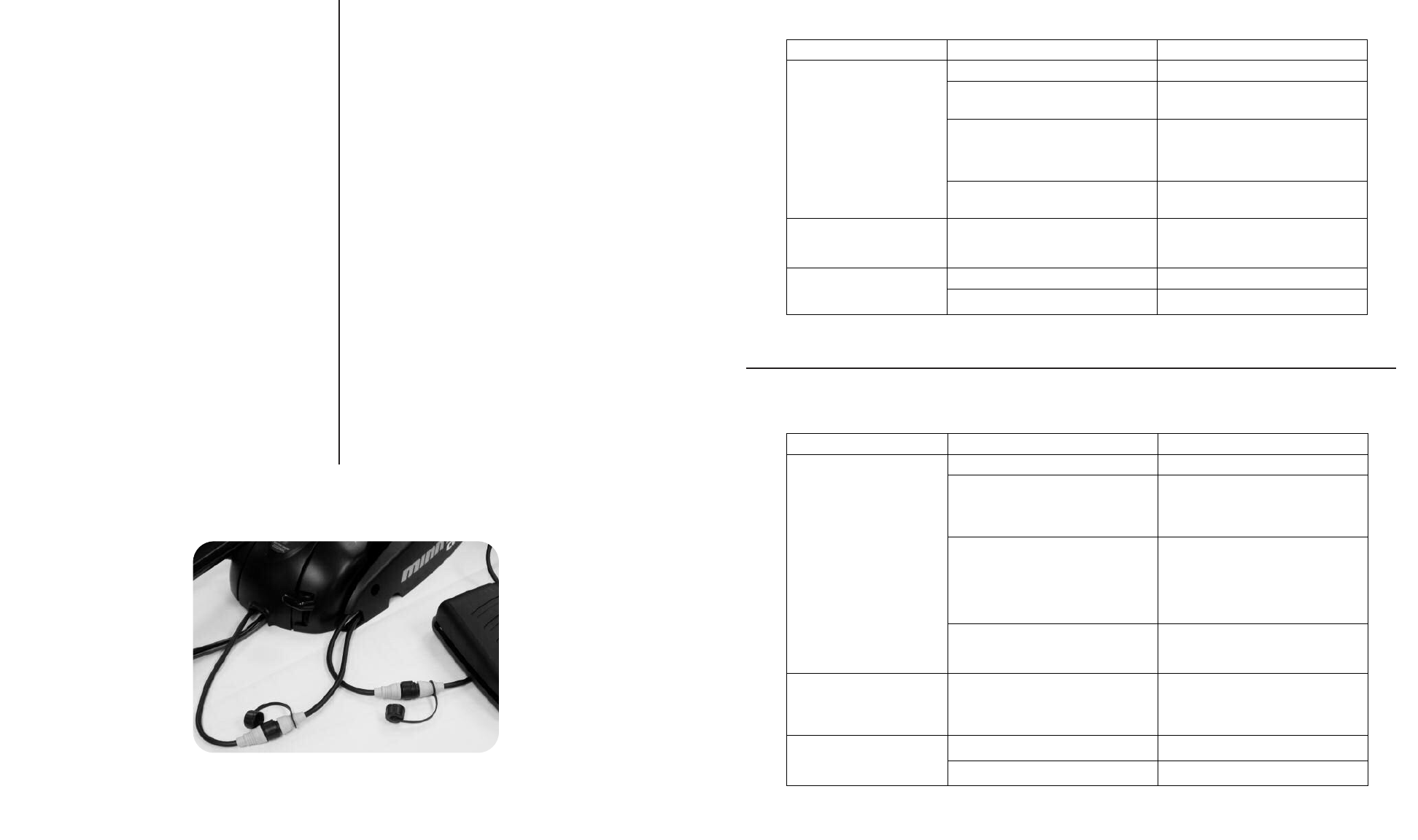
4.) Connect the motor cable plug (previously connected to
the corded foot pedal) to the CoPilot receiver cable
plug that has the female (sleeve) receptacles. If
desired, connect the corded foot pedal plug end to the
CoPilot receiver cable plug that has the male pins.
INSTALLATION DE VOTRE COPILOTE
Précautions de sécurité
Avant et pendant l’installation de votre copilote, assurez-
vous que les précautions suivantes soient suivies :
• Débranchez le courant arrivant au moteur de pêche à
la traîne.
• Si le moteur de pêche à la traîne est présentement
monté sur un bateau, le bateau devrait être stabilisé
afin d’éviter les mouvements inattendus. Il vous est
suggéré de mettre le bateau sur une remorque ou un
monte-bateau.
Outils requis
Pour installer le copilote, vous aurez besoin d’un tourne-
vis Phillips n° 2 afin de monter le récepteur et de pinces
coupantes à coupe latérale ou de ciseaux pour couper
les brides d’attache du montant de canne.
Installation du récepteur
1.) Au moyen du tournevis, enlevez les deux vis de ¼-20
x5/8 po (1,6 cm) de la plaque latérale droite du moteur.
2.) Positionnez le récepteur du copilote sur l’extérieur de la
plaque latérale droite (montrée dans la figure ci-des-
sous) de façon à ce que les trous de montage du
récepteur soient alignés sur les trous de montage de la
plaque latérale.
3.) Prenez les nouvelles vis de montage de ¼-20 x 1 ¾ po
(4,4 cm) fournies, insérez-les à travers le récepteur et
la plaque latérale dans les trous de vis d’origine de la
plaque latérale. Serrez les deux vis.
4.) Connectez la fiche du câble du moteur (auparavant
connectée à la pédale câblée) à la fiche du câble du
récepteur du copilote qui comporte les cosses femelles
(manchons). Si vous le désirez, connectez l’extrémité
fiche de la pédale câblée à la fiche du câble du récep-
teur du copilote qui comporte les cosses mâles.
13
4
TROUBLESHOOTING
DÉPANNAGE
CAUSE
CAUSECAUSE
CAUSE EFFECT
EFFECTEFFECT
EFFECT SOLUTION
SOLUTIONSOLUTION
SOLUTION
The battery is discharged Replace battery
Receiver may not have “learned” the ID
number of the remote.
Remote needs to be learned. See “
“ADDING/REMOVING REMOTES” section
to learn the remote ID number.
With the foot pedal connected, the MOM-
CON switch is in the CON position. An
audio response will be heard if a button is
pressed with the foot pedal in the CON
position.
The foot pedal switch must be placed in
the MOM position. The receiver will not
accept any commands from the remote
with the switch in the CON position
REMOTE IS NOT
TRANSMITTING
If remote has been taken apart, the
keypad and top case may have been
installed backwards.
Take remote apart (BATTERY
REPLACEMENT SECTION) and reinstall
case halves with the proper orientation.
WHEN RECEIVER IS
POWERED UP, IT SOUNDS A
BEEP PATTERN. (1 long beep,
2short beeps, pause, repeat)
The foot pedal MOM-CON switch is in the
CON position
The foot pedal switch must be placed in
the MOM position. The beeping sound will
continue until the switch is placed in the
MOM position
Prop speed is set at “0” Increase the prop speed above “0”
THE PROP IS NOT TURNING
BUT THE “PROP ON” AUDIO
TICK IS STILL GOING Prop ON tick occurs only in Audio mode 3 Switch Audio mode to either Audio 1 or 2.
See “Audio Modes” section.
CAUSE
CAUSECAUSE
CAUSE EFFET
EFFETEFFET
EFFET SOLUTION
SOLUTIONSOLUTION
SOLUTION
La pile est morte. Remplacez la pile.
Le récepteur peut ne pas avoir « appris »
le numéro d’identification de la commande
àdistance.
La commande doit être informée. Voyez
la section « AJOUTER/ENLEVER LES
COMMANDES À DISTANCE » pour
enseigner le numéro d’identification de la
commande.
La pédale étant connectée, l’interrupteur
MOM-CON est en position de
fonctionnement continu CON. Une
réponse audio se fera entendre si un
bouton est opprimé alors que l’interrupteur
de la pédale est en position de
fonctionnement continu CON.
L’interrupteur de la pédale doit être placé
en position de fonctionnement temporaire
MOM. Le récepteur n’acceptera pas
d’ordres de la commande à distance avec
l’interrupteur en position de
fonctionnement continu CON.
LA COMMANDE À DISTANCE
NE TRANSMET PAS.
Si la commande à distance a été
démontée, le bloc de touches et le boîtier
supérieur ont pu être assemblés à
l’envers.
Démontez la commande (SECTION SUR
LE REMPLACEMENT DE LA PILE) et
remontez les moitiés de boîtier dans le
bon sens.
QUAND LE RÉCEPTEUR EST
ALLUMÉ, IL ÉMET UNE SÉRIE
DE BIPS SONORES. (1 bip
long, 2 bips courts, une pause
et ceci se répète.)
L’interrupteur MOM-CON de la pédale est
en position de fonctionnement continu
CON.
L’interrupteur de la pédale doit être placé
en position de fonctionnement temporaire
MOM. Le bip sonore continuera jusqu’à
ce que l’interrupteur soit placé en position
de fonctionnement temporaire MOM.
La vitesse de l’hélice est réglée à « 0 ». Augmentez la vitesse de l’hélice au-
dessus de « 0 ».
L’HÉLICE NE TOURNE PAS
MAIS LE SON AUDIBLE «
D’HÉLICE EN MARCHE »
CONTINUE.
Le son de mise EN MARCHE de l’hélice
ne se produit qu’en mode audio 3.
Mettez le mode audio en Audio 1 ou 2.
Voyez la section sur les « Modes audio ».
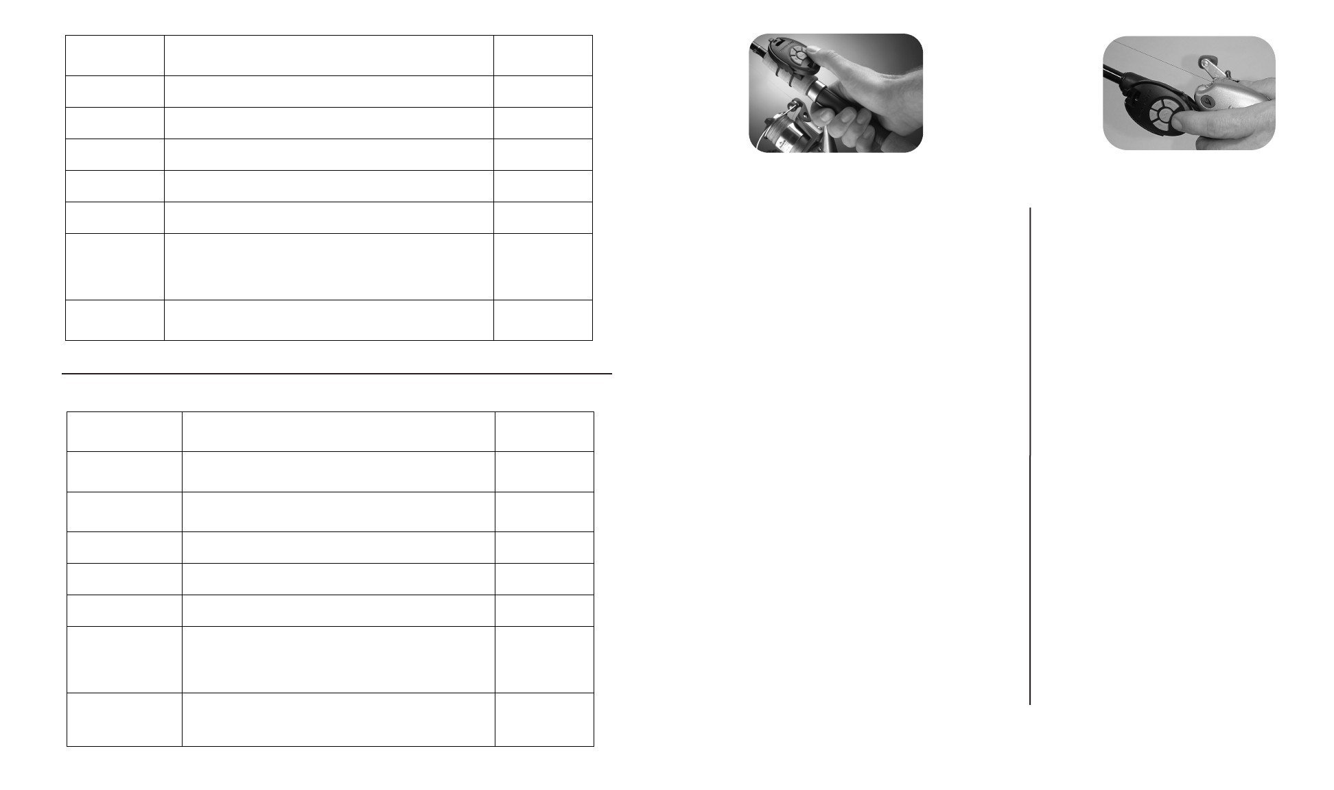
Installing the rod mount
• The rod mount is designed for installation on any area of
the rod grip, especially the area forward of the reel. (See
the figures above.)
• Spinning reel users may want to install the mount on the
top of the rod to allow thumb operation of the remote.
• Bait casting reel users who “palm” the reel may install the
mount on the side of the rod to allow remote operation
with the index or middle finger.
• The mount should be positioned on the rod so that the
unlocking latch on the bracket is toward the rod tip.
1). Position the rod mount in the desired location on
the fishing rod, holding it in place with your thumb.
2). Insert (2) tie-down straps through the rod mount
and cinch down around the rod (place the locking
head of the tie-down strap to either side of the rod
mount; do not place in the area below the remote.)
3). Trim the excess tie down strap with a side cutter
or scissors.
• To attach the remote to the mount, slide the remote into
the mount from the rear of the bracket. Ensure that the
slides on the mount engage the slots on the sides of the
remote. Slide the remote into the mount until it snaps
into the locked position.
• To release the remote from the mount, press down on
the unlocking latch while simultaneously sliding the
remote out of the mount.
• During periods of non-use, we recommend that the
remote be inserted into the mount with the buttons facing
down. This will help to ensure that there are no uninten-
tional button presses while the rod is in storage.
Installation du montant de canne
• Le montant de canne est conçu de façon à être installé
sur toute partie de la poignée de la canne, spécialement
la zone à l’avant de la bobine. (Voyez les figures ci-des-
sous.)
• Les utilisateurs de bobine rotative peuvent vouloir instal-
ler le montant sur le haut de la canne afin de pouvoir
contrôler la commande du pouce.
• Les utilisateurs de bobine à jeter l’appât qui contrôle la
bobine de la paume peuvent installer le montant sur le
côté de la canne afin de pouvoir contrôler la commande
de l’indexe ou du majeur.
• Le montant devrait être positionné sur la canne de façon
àdébloquer le loquet se trouvant sur le support en direc-
tion de la pointe de la canne.
1). Positionnez le montant de canne sur l’emplace-
ment désiré de la canne de pêche en le mainte-
nant en place de votre pouce.
2). Insérez deux (2) brides d’attache à travers le mon-
tant de canne et sanglez-les autour de la canne
(placez les têtes de blocage des brides d’attache
d’un côté du montant de canne ; ne les placez pas
dans la zone sous la commande à distance).
3). Coupez l’excès des brides d’attache au moyen de
pinces coupantes ou de ciseaux.
•Pour fixer la commande au montant, glissez-la dans le
montant de l’arrière du support. Assurez-vous que les
glissières du montant engagent les encoches aux côtés
de la commande. Glissez la commande dans le montant
jusqu’à ce qu’elle s’enclenche en position verrouillée.
•Pour sortir la commande du montant, enfoncez le loquet
de verrouillage tout en glissant simultanément la com-
mande hors du montant.
•Pendant les périodes sans utilisation, nous vous recom-
mandons d’insérer la commande dans le montant avec
les boutons orientés vers le bas. Ceci aidera à assurer
qu’aucun bouton ne soit enfoncé involontairement alors
que la canne est rangée.
5
12
SPINNING REEL
BOBINE ROTATIVE
BAIT CASTING REEL
BOBINE À JETER L’APPÂT
AUDIO
AUDIOAUDIO
AUDIO
PATTERN
PATTERNPATTERN
PATTERN WHAT CONDITION CAUSE IT
WHAT CONDITION CAUSE ITWHAT CONDITION CAUSE IT
WHAT CONDITION CAUSE IT
OCCURS IN
OCCURS INOCCURS IN
OCCURS IN
WHICH AUDIO
WHICH AUDIOWHICH AUDIO
WHICH AUDIO
MODE
MODEMODE
MODE
2second long
beep
Every time the receiver is powered up an there are no remote
IDs learned. All
1chirp When foot pedal is in the CON position all remote commands
from the remote will be ignored. All
5beeps Foot pedal speed control is moved while in remote mode. All
Steady tone Heard while holding down the learn button on the receiver. All
4beeps After a remote button is pressed while the receiver learns it's ID. All
Aten second
long warbling
sound that
transitions into a
steady tone
Heard during the process used to clear all stored remote IDs.
After the learn switch is released, a 2 second long beep will be
heard.
All
1long beep 2
short beeps,
pause, (repeat)
Powered up with MOM/CON in the CON position (or mom switch
held). When the foot pedal is moved to momentary, the power
up audio will be heard.
All
SÉRIE
SÉRIESÉRIE
SÉRIE
AUDIO
AUDIOAUDIO
AUDIO CAUSÉE PAR QUELLE CONDITION ?
CAUSÉE PAR QUELLE CONDITION ?CAUSÉE PAR QUELLE CONDITION ?
CAUSÉE PAR QUELLE CONDITION ?
SE PRODUIT
SE PRODUITSE PRODUIT
SE PRODUIT
DANS QUEL
DANS QUELDANS QUEL
DANS QUEL
MODE AUDIO ?
MODE AUDIO ?MODE AUDIO ?
MODE AUDIO ?
Bip de 2 secondes
Chaque fois que le récepteur est mis sous tension et
qu’aucun numéro d’identification de commande à distance
n’a été appris.
Tous
1gazouillement
Quand la pédale est en position de fonctionnement continu
CON, tous les ordres des commandes à distance seront
ignorés.
Tous
5bips Le contrôle de vitesse de la pédale est déplacé tout en étant
en mode de commande à distance. Tous
Son continu Se fait entendre alors que le bouton informant est tenu
enfoncé sur le récepteur. Tous
4bips Après qu’un bouton de la commande à distance est enfoncé
alors que le récepteur apprend son numéro d’identification. Tous
Un bruit de
gazouillis de dix
secondes qui
change en un son
continu
Se fait entendre au cours du processus servant à effacer
tous les numéros d’identification de commande à distance.
Après que le bouton informant est relâché, un bip de 2
secondes se fera entendre.
Tous
1bip long,
2bip courts,
une pause (ceci se
répétant)
Mis sous tension avec l’interrupteur MOM/CON en position
CON (ou maintenu en position MOM). Quand la pédale est
mise en fonctionnement temporaire, l’initialisation audio se
fait entendre.
Tous
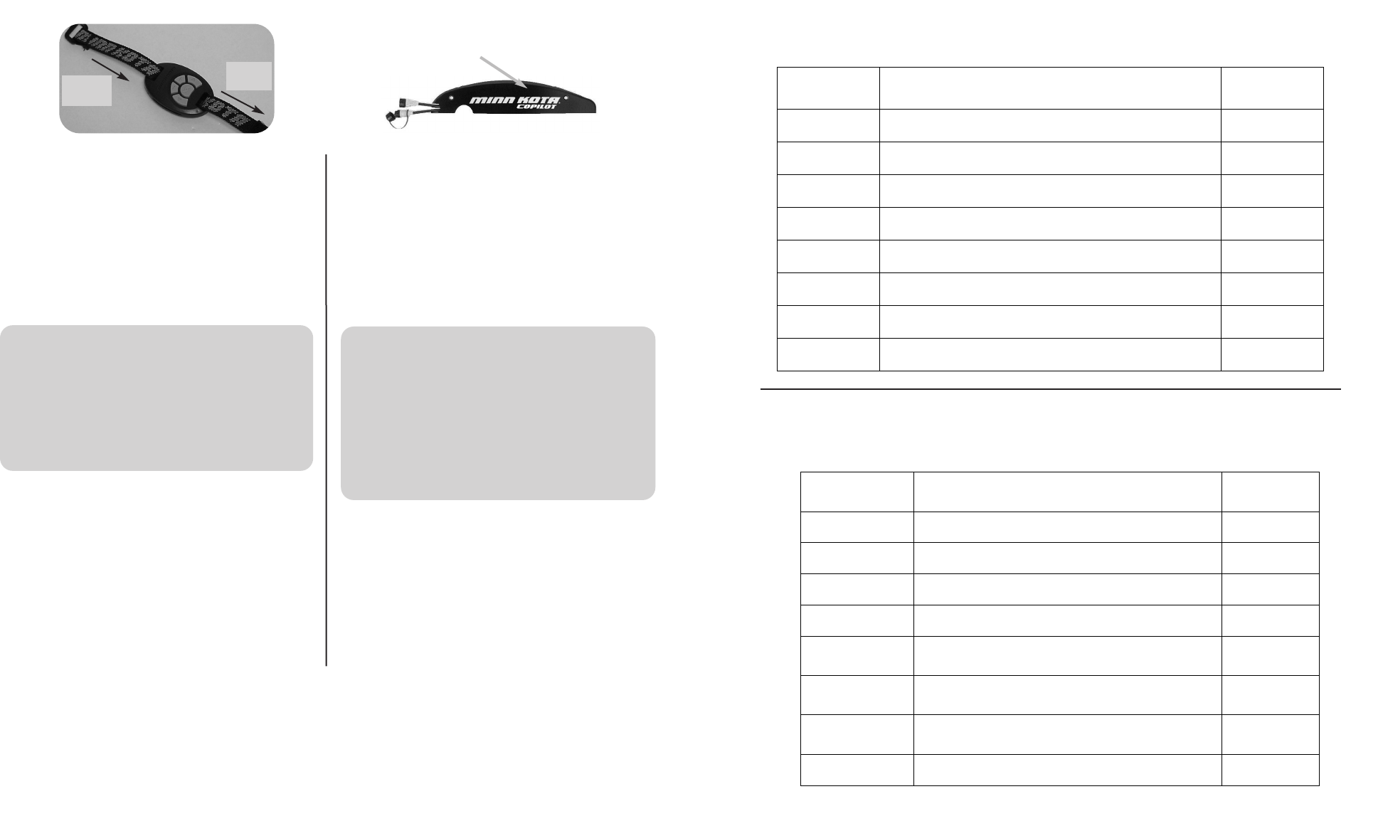
Using the nylon strap with the hand remote
For a general purpose strap mount, refer to the figure
above. This strap can be used as a wrist mount, around
the belt, to a fixed location on the boat, etc…
Your CoPilot is now installed and ready for operation!
ADDING / REMOVING REMOTES
• To “learn” the ID number of additional remotes, follow these
steps:
1.) Press and hold the LEARN button located on the side
of the receiver (receiver will emit a continuous tone.)
Asmall blunt object must be used to depress the
LEARN button ( pen or screwdriver.)
2.) Press any button on the remote (receiver will beep 4
times confirming that it has “learned” the ID number of
the remote and that the programming is valid and com-
plete.)
Utilisation de la courroie de nylon avec la main commande
Pour monter la courroie dans un but général, reportez-
vous à la figure ci-dessous. Cette courroie peut être uti-
lisée sur le poignet, autour de la ceinture, sur un endroit
fixe du bateau, etc.
Votre copilote est maintenant installé et prêt à être utilisé !
AJOUTER/ENLEVEZ LES COMMANDES À DISTANCE
• Pour « enseigner » le numéro d’identification des com-
mandes à distance additionnelles, suivez ces étapes :
1.) Enfoncez et tenez le bouton INFORMANT situé sur le
côté du récepteur (le récepteur émettra un son conti-
nu).
Un petit objet émoussé doit être utilisé pour enfoncer le
bouton IMFORMANT (stylo ou tournevis).
2.) Enfoncez un bouton sur la commande (le récepteur
émettra 4 bipssonores pour confirmer qu’il a « appris
»le numéro d’identification de la commande à distan-
ce et que sa programmation est valide et terminée).
116
LEARN BUTTON
BOUTON INFORMANT
IN
ENTRÉE
OUT
SORTIE
THE COPILOT RECEIVER IN THIS KIT HAS ALREADY
“LEARNED” THE ID NUMBER OF THE REMOTE IT IS PACK-
AGED WITH. THE RECEIVER MUST “LEARN” THE ID
NUMBER OF ANY ADDITIONAL REMOTE(S) THAT YOU
INTEND TO USE. WHEN THE RECEIVER LEARNS THE
ID NUMBER OF A REMOTE, THAT ID NUMBER IS
RETAINED IN THE RECEIVER EVEN WHEN THE
MOTOR IS DISCONNECTED FROM ITS POWER
SOURCE.
LE RÉCEPTEUR DU COPILOTE DANS CE NÉCESSAIRE A
DÉJÀ « APPRIS » LE NUMÉRO D’IDENTIFICATION DE LA
COMMANDE À DISTANCE QUI AÉTÉ EMBALLÉE AVEC LUI.
LE RÉCEPTEUR DOIT « APPRENDRE » LE NUMÉRO
D’IDENTIFICATION DE TOUTE(S) COMMANDE(S) À
DISTANCE SUPPLÉMENTAIRE(S) QUE VOUS VOULEZ
UTILISER. QUAND LE RÉCEPTEUR APPREND LE
NUMÉRO D’IDENTIFICATION D’UNE COMMANDE À
DISTANCE, CE NUMÉRO D’IDENTIFICATION EST
RETENU DANS LE RÉCEPTEUR MÊME SI LE MOTEUR
EST DÉBRANCHÉ DE SA SOURCE D’ÉNERGIE.
NOTE : WHEN THE CORDED FOOT PEDAL IS IN CONTROLAND THE PROPELLER IS ON, THE PROP ON INDICATOR CLICK
WILL BE HEARD IF THE RECEIVER IS SET TO AUDIO MODE 3.
REMARQUE : QUAND LA PÉDALE CÂBLÉE EST L’APPAREIL QUI CONTRÔLE LE MOTEUR ET L’HÉLICE EST EN
MARCHE, LE DÉCLIC INDICATEUR D’HÉLICE EN MARCHE NE SE FERA ENTENDRE QUE SI LE RÉCEPTEUR EST EN
MODE AUDIO 3.
AAUUDDIIOO
PPAATTTTEERRNNWWHHAATTCCOONNDDIITTIIOONNCCAAUUSSEEIITT
OOCCCCUURRSSIINN
WWHHIICCHHAAUUDDIIOO
MMOODDEE
1beep Pressing the
IINNCCRREEAASSEESSPPEEEEDD
or
DDEECCRREEAASSEESSPPEEEEDD
button. Modes 2 and 3
1beep Pressing the
PPRROOPPOONN//OOFFFF
button to turn the prop on. Modes 2 and 3
2beeps Pressing the
PPRROOPPOONN//OOFFFF
button to turn the prop off. Mode 2 and 3
Single tick every
1.5 sec. When the prop is active including when speed is set to 0. Mode 3
1beep Switching to Audio Mode 1 (pressing the
IINNCCRREEAASSEESSPPEEEEDD
and
DDEECCRREEAASSEESSPPEEEEDD
buttons simultaneously for 1 second.) All
2beeps Switching to Audio Mode 2 (pressing the
IINNCCRREEAASSEESSPPEEEEDD
and
DDEECCRREEAASSEESSPPEEEEDD
buttons simultaneously for 1 second.) All
3beeps Switching to Audio Mode 3 (pressing the
IINNCCRREEAASSEESSPPEEEEDD
and
DDEECCRREEAASSEESSPPEEEEDD
buttons simultaneously for 1 second.) All
1chirp Every time the receiver is powered up and there is at least one
remote ID learned. All
SSÉÉRRIIEE
AAUUDDIIOOCCAAUUSSÉÉEEPPAARRQQUUEELLLLEECCOONNDDIITTIIOONN??
SSEEPPRROODDUUIITT
DDAANNSSQQUUEELL
MMOODDEEAAUUDDIIOO??
1bip Enfoncer le bouton d’
AACCCCÉÉLLÉÉRRAATTIIOONN
ou de
DDÉÉCCÉÉLLÉÉRRAATTIIOONN
.Modes 2 et 3
1bip Enfoncer le bouton de
MMIISSEEEENNMMAARRCCHHEE//ÀÀLL’’AARRRRÊÊTTDDEE
LL’’HHÉÉLLIICCEE
pour mettre en marche l’hélice. Modes 2 et 3
2bips Enfoncer le bouton de
MMIISSEEEENNMMAARRCCHHEE//ÀÀLL’’AARRRRÊÊTTDDEE
LL’’HHÉÉLLIICCEE
pour arrêter l’hélice. Modes 2 et 3
Un son toutes les
1,5 s
Quand l’hélice est en marche, y compris quand la vitesse est
à0. Mode 3
1bip
Passer au mode audio 1 (en enfonçant les boutons
d’
AACCCCÉÉLLÉÉRRAATTIIOONN
et de
DDÉÉCCÉÉLLÉÉRRAATTIIOONN
simultanément
pendant 1 seconde).
Tous
2bips
Passer au mode audio 2 (en enfonçant les boutons
d’
AACCCCÉÉLLÉÉRRAATTIIOONN
et de
DDÉÉCCÉÉLLÉÉRRAATTIIOONN
simultanément
pendant 1 seconde).
Tous
3bips
Passer au mode audio 3 (en enfonçant les boutons
d’
AACCCCÉÉLLÉÉRRAATTIIOONN
et de
DDÉÉCCÉÉLLÉÉRRAATTIIOONN
simultanément
pendant 1 seconde).
Tous
1gazouillement Chaque fois que le récepteur est mis sous tension et qu’au
moins un numéro d’identification de commande a été appris. Tous
• “Re-learning” the ID number of the same remote will not over-
write previously “learned” remotes.
• If the receiver has “learned” the ID number of ten remotes,
“learning” an eleventh remote will erase or over write the first
“learned” remote.
• The CoPilot allows the angler to erase all stored remote ID
numbers from the receiver. To do so, follow these steps:
1.) Remove power from the receiver by unplugging the
receiver from the motor.
2.) Press and hold the LEARN button and power up the
receiver by plugging it back into the motor. Hold the
LEARN button down for 10 seconds. During this time the
receiver audio will emit a warble sound, slowly transition to
aconstant beep and then shut off.
3.) Release the Learn button and the receiver will reboot. The
receiver will emit a 2 second long beep indicating memo-
ry is empty. This audio pattern will occur each time the
receiver powers up until a remote ID number is learned.
MISCELLANEOUS INFORMATION
• The five buttons are for PROP ON/OFF, STEER LEFT,
STEER RIGHT, INCREASE SPEED AND DECREASE
SPEED.
• Pressing the PROP ON/OFF button will turn the propeller on
or off. The button does not need to be held down. (Press the
button once to turn the motor ON; press button a second time
to turn it OFF.)
• Pressing either STEERING button or left or right side of the
wireless pedal, will cause the motor to turn in the desired direc-
tion as long as the button or pedal buton is held down. If a
steering button or pedal button is held for more than seven
seconds, the steering will automatically stop.
• Pressing and releasing the INCREASE SPEED or
DECREASE SPEED buttons will cause the speed to
increase or decrease by one level. The speed is adjustable
from level 0-10. At level 0, the prop will not turn.
•An audible beep is heard for each step change in speed.
Attempting to go higher than speed 10 or lower than speed 0
will result in the speed not changing and no beep will be
heard. See the Audio Mode section for more information.
• If the receiver senses no corded foot pedal or remote opera-
tion for 1 hour, the remote speed setting is automatically set to
zero. This could help prevent unintentional activation of the
propeller if the prop on /offremote button is inadvertently
pressed or bumped while in storage.
• « Enseigner de nouveau » le numéro d’identification de la
même commande ne remplacement pas ceux des com-
mandes auparavant « appris ».
• Si le récepteur a « appris » le numéro de dix commandes à
distance, en « apprendre » un onzième effacera ou rempla-
cera le premier « appris ».
• Le copilote permet au pêcheur d’effacer tous les numéros
d’identification des commandes enregistrés du récepteur.
Pour faire ceci, suivez ces étapes :
1.) Coupez le courant arrivant au récepteur en le débran-
chant du moteur.
2.) Enfoncez et tenez enfoncé le bouton INFORMANT,puis
connectez de nouveau le récepteur au moteur. Tenez
enfoncé le bouton INFORMANT pendant 10 secondes.
Pendant ce temps, la sonnerie du récepteur émettra un
bruit de gazouillis, qui changera doucement en un bip
sonore continu, puis s’arrêtera.
3.) Relâchez le bouton informant et le récepteur se réinitiali-
sera. Le récepteur émettra 4 gazouillements suivis par un
bip sonore de 1 seconde indiquant que sa mémoire est
vide. Cette série de sons se produira chaque fois que le
récepteur est mis sous tension et ce jusqu’à ce qu’un
numéro d’identification soit appris.
INFORMATION DIVERSE
• Les cinq boutons sont destinés à METTRE L’HÉLICE EN
MARCHE/À L’ARRÊT, TOURNER À GAUCHE, TOUR-
NER À DROITE, ACCÉLÉRER ET DÉCÉLÉRER.
• Appuyer sur le bouton de mise EN MARCHE/À L’ARRÊT
DE L’HÉLICE fera tourner ou arrêtera l’hélice. Il n’est pas
nécessaire de tenir le bouton enfoncé. (Appuyez sur le bou-
ton une fois pour mettre le moteur EN MARCHE ; appuyez
sur le bouton une deuxième fois pour l’ARRÊTER.)
• Appuyer sur l’un des boutons de DIRECTION ou quitté ou le
côté juste de la pédale sans fil, tournera le moteur dans la
direction désirée tant que le bouton sera enfoncé. Si un bou-
ton de direction est tenu pendant plus de sept secondes, la
direction s’arrêtera automatiquement.
•Appuyer sur et relâcher les boutons pour ACCÉLÉRER ou
DÉCÉLÉRER augmentera ou diminuera la vitesse d’un
niveau. La vitesse est réglable des niveaux 0 à 10. Au niveau
0, l’hélice ne tournera pas.
• Un bip sonore est émis pour chaque changement de niveau
de vitesse. Essayer d’accélérer au-dessus du niveau 10 ou
de décélérer sous le niveau 0 ne changera pas la vitesse et
aucun bip sonore ne se fera entendre. Voyez la section sur
le Mode audio pour plus de renseignements.
•Si le récepteur ne détecte aucune action de la pédale ou de
la commande à distance pendant 1 heure, le niveau de vites-
se de la commande à distance sera automatiquement réduit
à0. Ceci pourrait aider à éviter la mise en marche involontai-
re de l’hélice au cas où le bouton de marche/arrêt de la com-
mande à distance serait par inadvertance enfoncé ou heurté
quand entreposé.
7
10
Using the CoPilot without the corded foot pedal
• Some anglers will prefer to have the deck completely clear
of any unnecessary cables and corded foot pedals. When
using the Copilot in this manner, the receiver will always
react to any commands from the remote.
AUDIO MODES
• There are three receiver audio modes available. To switch
from one audio mode to another on the key remote, press
and hold both the INCREASE and DECREASE speed but-
tons on the remote down for one second. The receiver will
respond with 1, 2 or 3 audible beeps indicating the corre-
sponding receiver audio mode change.
Audio Mode 1 = All of the normal audible sounds mentioned
in this owners manual.
Audio Mode 2 = Same as audio mode 1 plus an audible
beep for speed increase / decrease and prop on/off.
Audio Mode 3 = Same as audio mode 2 plus the prop on
audible click every few seconds.
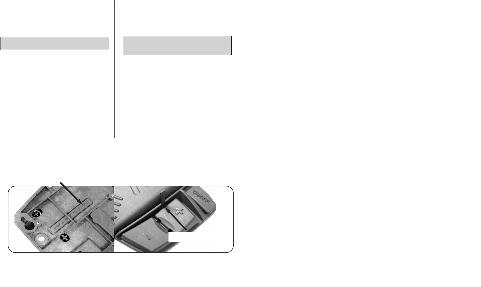
• To switch between audio modes on the wireless foot pedal,
insert the audio mode adjustment stick from the back of the
pedal into the slot next to the speed marked “+”. Pushing the
stick and the “-” down at the same time for one second will
toggle through the 3 audio modes.
Utilisation du copilote sans pédale câblée
• Quelques pêcheurs préféreront avoir le pont complètement
dégagé de tout câble inutile et de pédales. Quand vous utilisez
le copilote de cette manière, le récepteur réagit toujours aux
ordres de la commande à distance.
MODES AUDIO
•Trois modes audio sont disponibles sur le récepteur. Pour passer
d’un mode audio à l’autre, appuyez sur et tenez appuyé les deux
boutons d’ACCÉLÉRATION et de DÉCÉLÉRATION sur la
commande à distance pendant une seconde. Le récepteur
répondra par 1, 2 ou 3 bips sonores indiquant ainsi le passage
au mode audio correspondant sur le récepteur.
Mode audio 1 = Tous les sons audibles normaux mentionnés
dans ce manuel du propriétaire.
Mode audio 2 = Identique au mode audio 1 plus un bip sonore
audible lors de l’accélération, la décélération et la mise en
marche/à l’arrêt de l’hélice.
Mode audio 3 = Identique au mode audio 2 plus un déclic
audible indiquant que l’hélice est en marche toutes les
quelques secondes.
• Pour changer de mode audio sur la pédale sans fil, insérez le
bâtonnet de réglage de mode audio dans la fente au dos près
de la vitesse marquée « + ». Enfoncer le bâtonnet et le « - »
simultanément pendant une seconde passera d’un des 3 modes
audio à l’autre.
UNIT IS FACTORY PRE-SET TO AUDIO MODE 2. L’UNITÉ EST PRÉRÉGLÉE EN USINE SUR LE MODE
AUDIO 2.
MODE ADJUSTMENT STICK
BÂTONNET DE RÉGLAGE DE MODE
STICK INSERTED INTO SLOT
BÂTONNET INSÉRÉ DANS LA FENTE
BATTERY REPLACEMENT, HAND REMOTE
THE REPLACEMENT BATTERY MUST BE A MODEL
CR2032 COIN CELL TYPE. IT IS STRONGLY RECOM-
MENDED THAT A NAME BRAND BATTERY IS USED.
To replace the battery, follow these steps:
1.) Temporarily ground yourself by touching a ground-
ed metal object in order to discharge any static elec-
tricity in your body.
2.) Remove the four screws on the bottom of the
remote case.
3.) Separate the case halves to access the circuit
board.
4.) Pull back the retaining fingers of the battery holder
to remove the battery (underside of circuit board.)
5.) Install the new battery with the positive (+) side of
the battery facing up (away from the circuit board).
Ensure battery is snapped securely in place.
6.) Reassemble the remote. Note that the alignment
peg in the remote case must line up with the corre-
sponding alignment hole in the circuit board. Also
note that the keypad must be positioned so that the
buttons are over the end of the circuit board oppo-
site from the alignment peg and hole. Reinstall the
four case screws and tighten them as required.
REMPLACEMENT DE LA PILE, EXTÉRIEUR DE MAIN
LA PILE DE RECHANGE DOIT ÊTRE DU TYPE À CEL-
LULE DE TAILLE DE PIÈCE DE MONNAIE, MODÈLE
CR2032. IL VOUS EST FORTEMENT RECOMMANDÉ
D’UTILISER UNE PILE D’UNE MARQUE RENOMMÉE.
Pour changer la pile, suivez ces étapes :
1.) Mettez-vous à la terre temporairement en touchant
un objet métallique mis à la masse de façon à
décharger toute électricité statique de votre corps.
2.) Enlevez les quatre vis du bas du boîtier de la com-
mande à distance.
3.) Séparez les moitiés du boîtier afin d’avoir accès au
circuit imprimé.
4.) Reculez les doigts de retenues du support de pile
pour enlever la pile (dessous du circuit imprimé).
5.) Installez la nouvelle pile avec son côté positif (+)
orienté vers le haut (à l’opposé du circuit imprimé).
Assurez-vous que la pile s’emboîte fermement
en place.
6.) Remontez la commande. Remarquez que la che-
ville d’alignement dans le boîtier de la commande à
distance doit être alignée sur le trou d’alignement lui
correspondant dans le circuit imprimé. Remarquez
aussi que le bloc de touches doit être positionné de
façon à ce que les boutons se trouvent au-dessus
de l’extrémité du circuit imprimé opposée au trou et
àla cheville d’alignement. Remontez les quatre vis
du boîtier et serrez-les comme requis.
98
BATTERY
PILE
ALIGNMENT PEG
CHEVILLE D’ALIGNEMENT
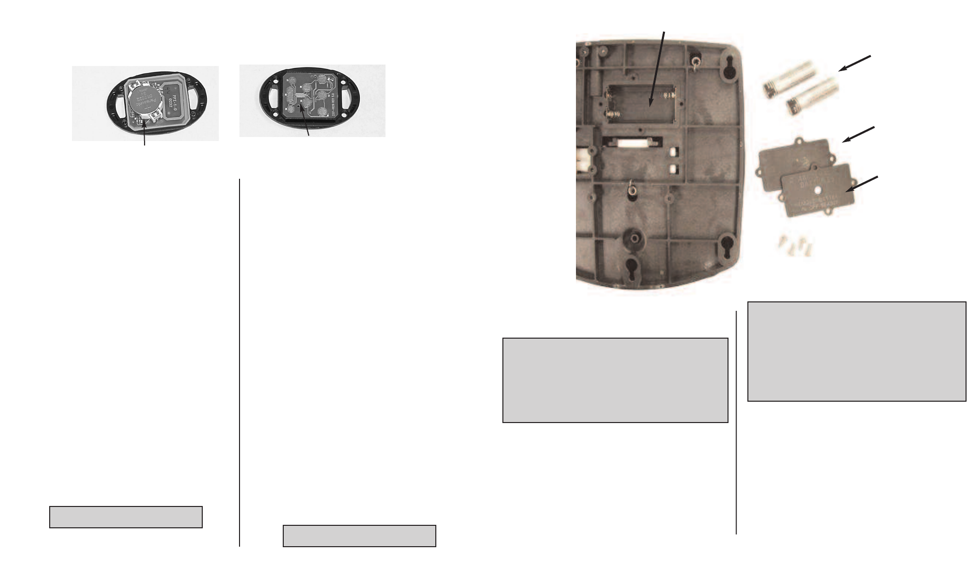
BATTERY REPLACEMENT, FOOT PEDAL REMOTE
THE REPLACEMENT BATTERIES MUST BE SIZE AA.
IT IS STRONGLY RECOMMENDED THAT A NAME
BRAND ALKALINE BATTERY IS USED.
Toreplace the battery,follow these steps:
1.) Remove the four screws from battery cover on the
bottom of the foot pedal.
3.) Remove battery cover and gasket.
5.) Install the new batteries with the positive (+) side of
the battery orientated as shown on pedal.
6.) Reassemble by replacing the gasket and cover.
See picture next page
BATTERIES
2ALKALINE AA
REQUIRED
2ALCALIN AA EXIGÉ
DO NOT OVER TIGHTEN
REMPLACEMENT DES PILES, COMMANDE À DISTANCE ET PÉDALE
LES PILES DE RECHANGE DOIVENT ÊTRE DE
TAILLE AA. IL VOUS EST fortement recommandé
D’UTILISER DES PILES ALCALINES DE MARQUE
RECONNUE.
Pour remplacer les piles, suivez ces étapes :
1.) Enlevez les quatre vis du couvercle des piles au bas de la
pédale.
3.) Enlevez le couvercle des piles et le joint.
5.) Installez les nouvelles piles le côté positif (+) de chaque pile
orienté comme montré sur la pédale.
6.) Remettez le joint et le couvercle.
Voir la photo la page suivante
NE SERREZ PAS TROP
BATTERY COMPARTMENT
COMPARTIMENT DE BATTERIE
GENERAL OPERATION
Using the hand remote or wireless pedal with the
corded foot pedal
•When the MOM-CON switch is in the MOM position, the
angler may begin using the remote at any time.
•As soon as any remote button is pressed, the initial speed
setting will be approximately the same as the corded foot
pedal’sspeed control position. However, the prop will not
automatically turn on until the remote’sprop on/off button is
pressed.
• Pressing the corded foot pedal momentary switch or steer-
ing switches will override the remote and receiver function
and control will automatically go to the corded foot pedal.
The prop speed will also revert to the current position of the
speed control on the corded foot pedal.
FONCTIONNEMENT GÉNÉRAL
Utilisation du main lointaine ou pédale sans fil avec la
pédale câblée
• Quand l’interrupteur MOM-CON est en position de fonction-
nement temporaire MOM, le pêcheur peut utiliser la comman-
de à distance à tout moment.
• Aussitôt qu’un bouton de la commande est enfoncé, le régla-
ge de vitesse initiale devient approximativement le même que
celui offert par la position du contrôle de vitesse de la pédale.
Néanmoins, l’hélice ne se mettra pas automatiquement en
marche sans tout d’abord appuyer sur le bouton de mise en
marche/à l’arrêt de l’hélice situé sur la commande à distance.
•Appuyer sur l’interrupteur de fonctionnement temporaire ou
sur les interrupteurs de direction de la pédale câblée annulera
la fonction de la commande à distance et du récepteur et le
contrôle du moteur retournera automatiquement à la pédale
câblée. La vitesse de l’hélice retournera aussi à celle établie
par la position actuelle du contrôle de vitesse de la pédale.
When the corded foot pedal’s MOM-CON switch is in the
CON position or when the Momentary On switch is held, the
receiver WILL NOT RESPOND to any remote commands.
When remote commands are received, the receiver will emit
an audio chirp. This will indicate that the remote is func-
tioning properly although a corded foot pedal switch is
active and is overriding the remote.
Pendant que l’interrupteur MOM-CON de la pédale est sur
la position de fonctionnement continu CON ou tenu en
position de fonctionnement temporaire, le récepteur NE
RÉPOND à aucun ordre de la commande à distance.
Quand les ordres de la commande seront reçus, le récep-
teur émettra un gazouillement audible. Ceci indiquera que
la commande à distance fonctionne correctement bien
que l’interrupteur de la pédale soit actif et ait priorité sur la
commande.
GASKET
JOINT
COVER
COUVERTURE