Joongang Telecom JD-LITE DVRs Card User Manual Manual English 2
Joongang Telecom Co., Ltd. DVRs Card Manual English 2
UserManual.wiki
>
Joongang Telecom
>
JD LITE User Manual
users manual
Navigation menu
Upload a User Manual
Namespaces
Wiki Guide
HTML
PDF
Info
Views
User Manual
Discussion / Help
Navigation


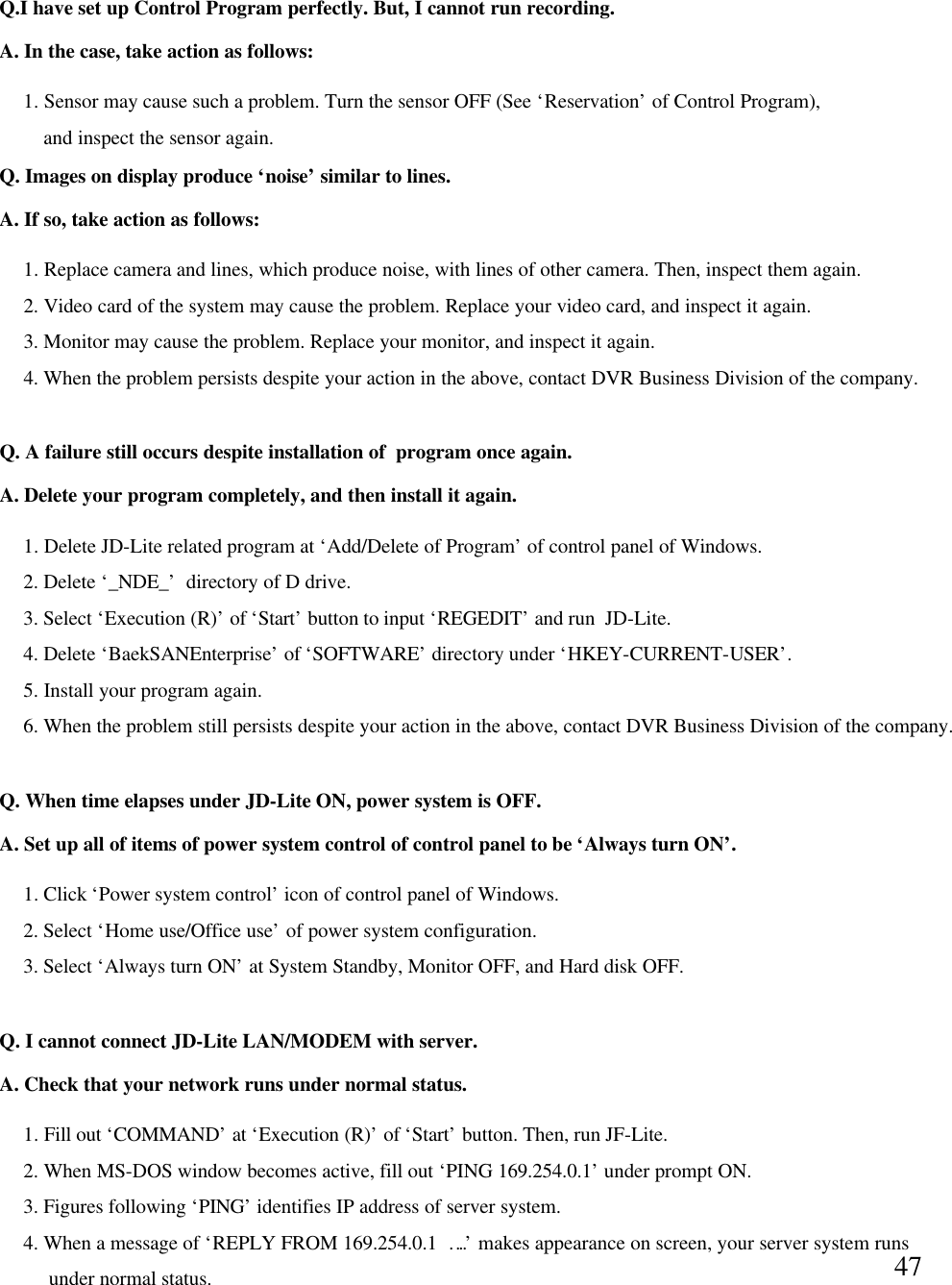
![81-3-3 Select ‘Controller’, and thenclick Registration Information. 1-3-4 Make Registration Informationwindow become active. Then,a message of ‘The system runscorrectly’indicates normal installationof the system. 1-3 JD-Lite System Operation Check1-3-1 At first, click My Computer icon, andthen click right-hand button of mouse todisplay menu in the below. Then, clickregistration information. 1-3-2 Make System Registration Informationwindow become active. Check thata controller named ‘VideoCapture64[BSR1000]’has been registered in‘Sound, Video and Game Controller’.](https://usermanual.wiki/Joongang-Telecom/JD-LITE/User-Guide-129940-Page-8.png)
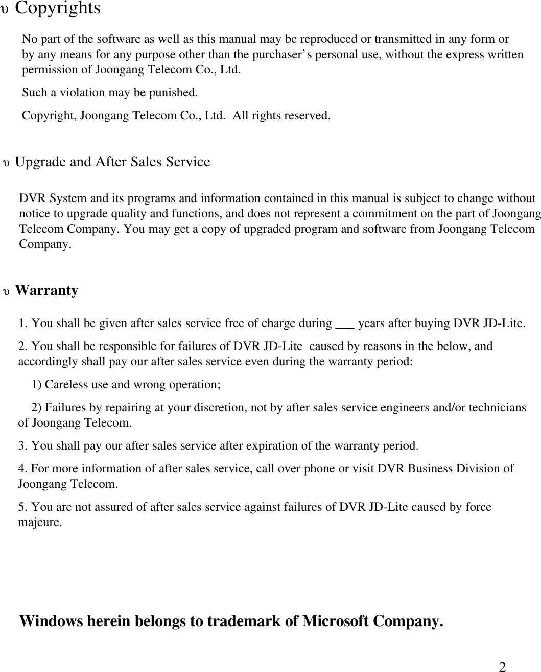
![91-4-3 Select `GENERIC IDE DISK TYPE`,Then Click [Properties]1-3-4 Click [Settings],select DMA.Then reboot the system to complete set-up DMA function.1-4 Set-up HDD DMA Function1-4-1 At first, click My Computer icon, andthen click right-hand button of mouse todisplay menu in the below. Then, clickregistration information. 1-4-2 After window become active,Click Disk Drives.](https://usermanual.wiki/Joongang-Telecom/JD-LITE/User-Guide-129940-Page-9.png)
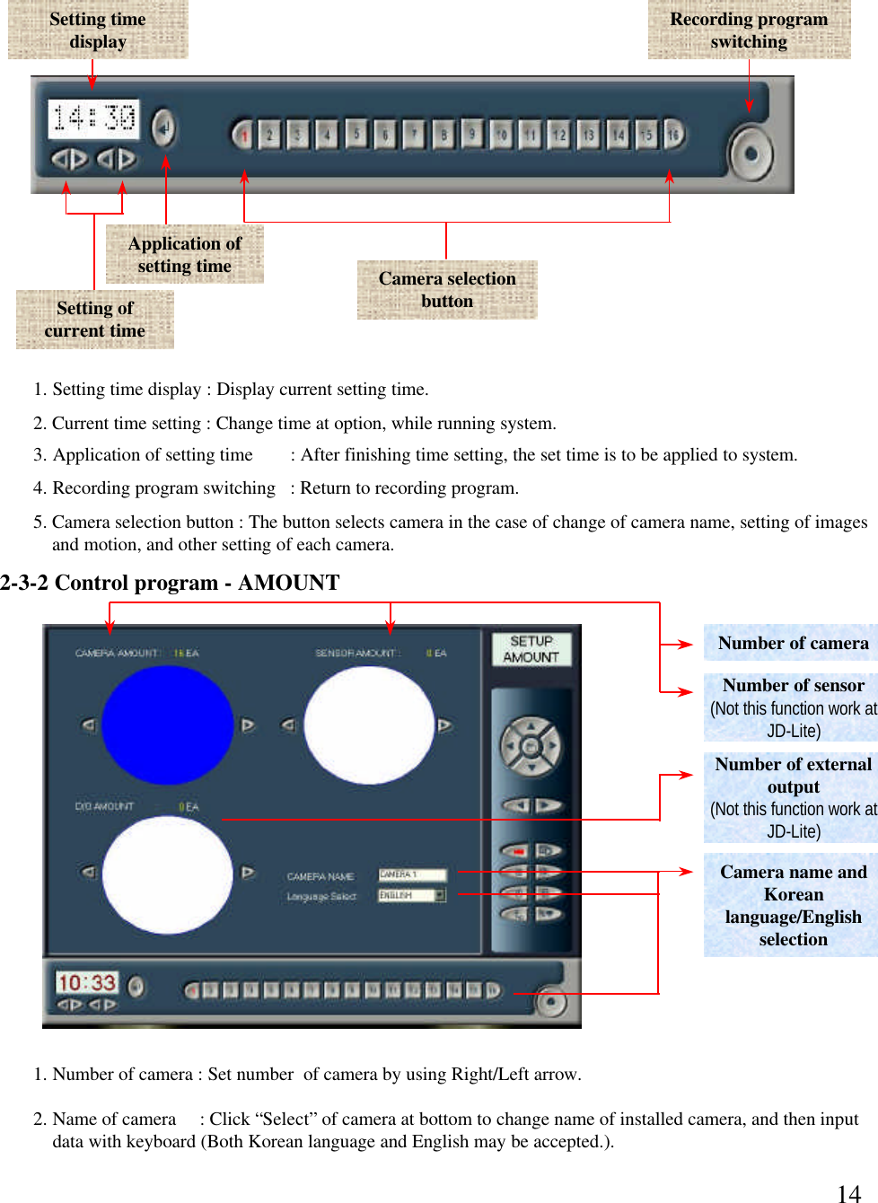
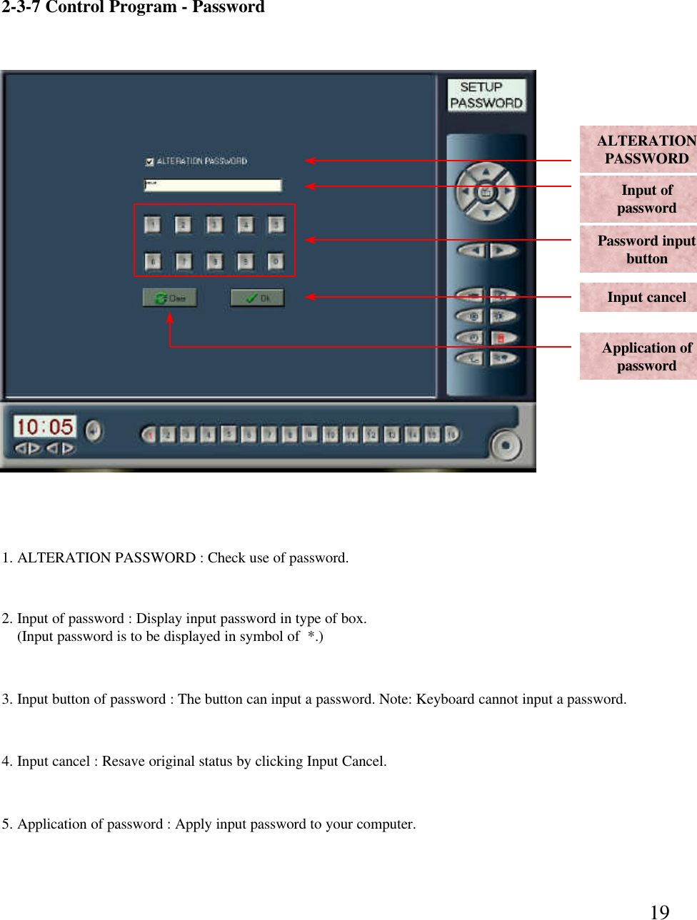
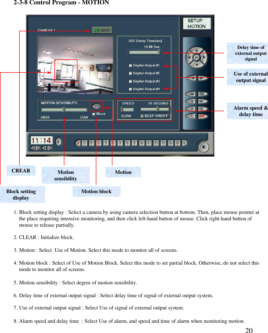
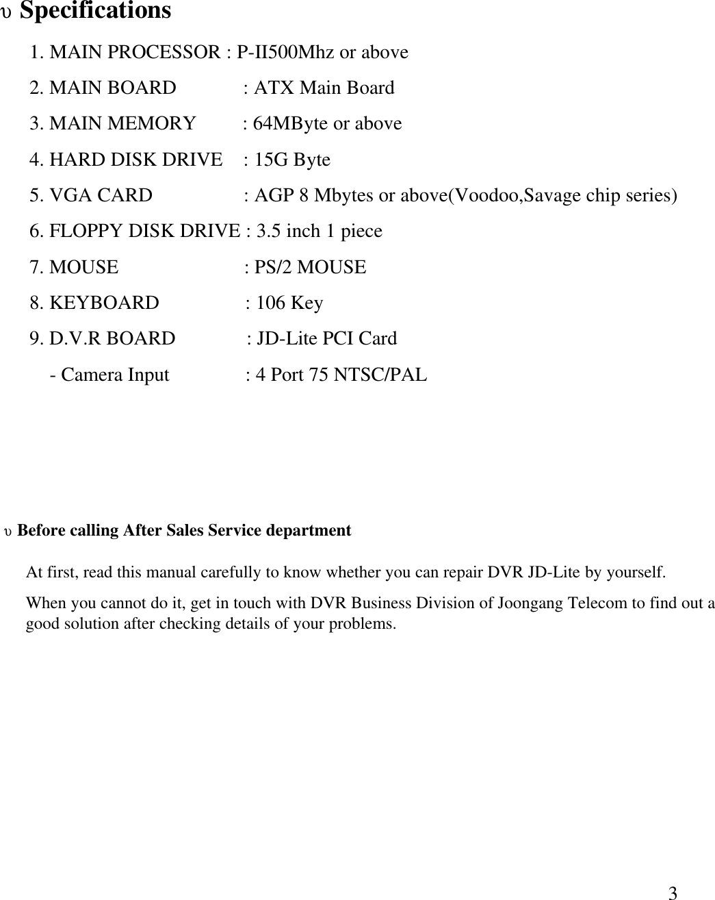
![337. Password8. Motion sensibility and Scope Set Up1. MOTION SENSIBILITY : You can adjust sensibility of motion. High sensibility can check even minor movement to send alarm and/or signal to external output system. Click Block Box to perceive area that you want. You can select Block at several areas. If no Block is selected, you may monitor overall screen. (Motion Sensibility operates only when sensor shaped button turn red-colored lamp ON.)2. D/O Delay Time : You may set Delay Time to delay signal to external output system, and select external output system to send a signal. 3. BEEP ON / OFF : Under Motion Sensibility mode, you may set alarm speed and delay time by using Use ofAlarm. Input of PasswordClick ‘ALTERATION PASSWORD’to let button become active to input password. Click the button to input password. Then, click ‘OK’to display a question message on saving of the password. Click ‘Yes’to save the password. Otherwise, click ‘Clear’to cancel input of the password. [However, this mode shall be applied to only Control Program-Set Up.]](https://usermanual.wiki/Joongang-Telecom/JD-LITE/User-Guide-129940-Page-33.png)

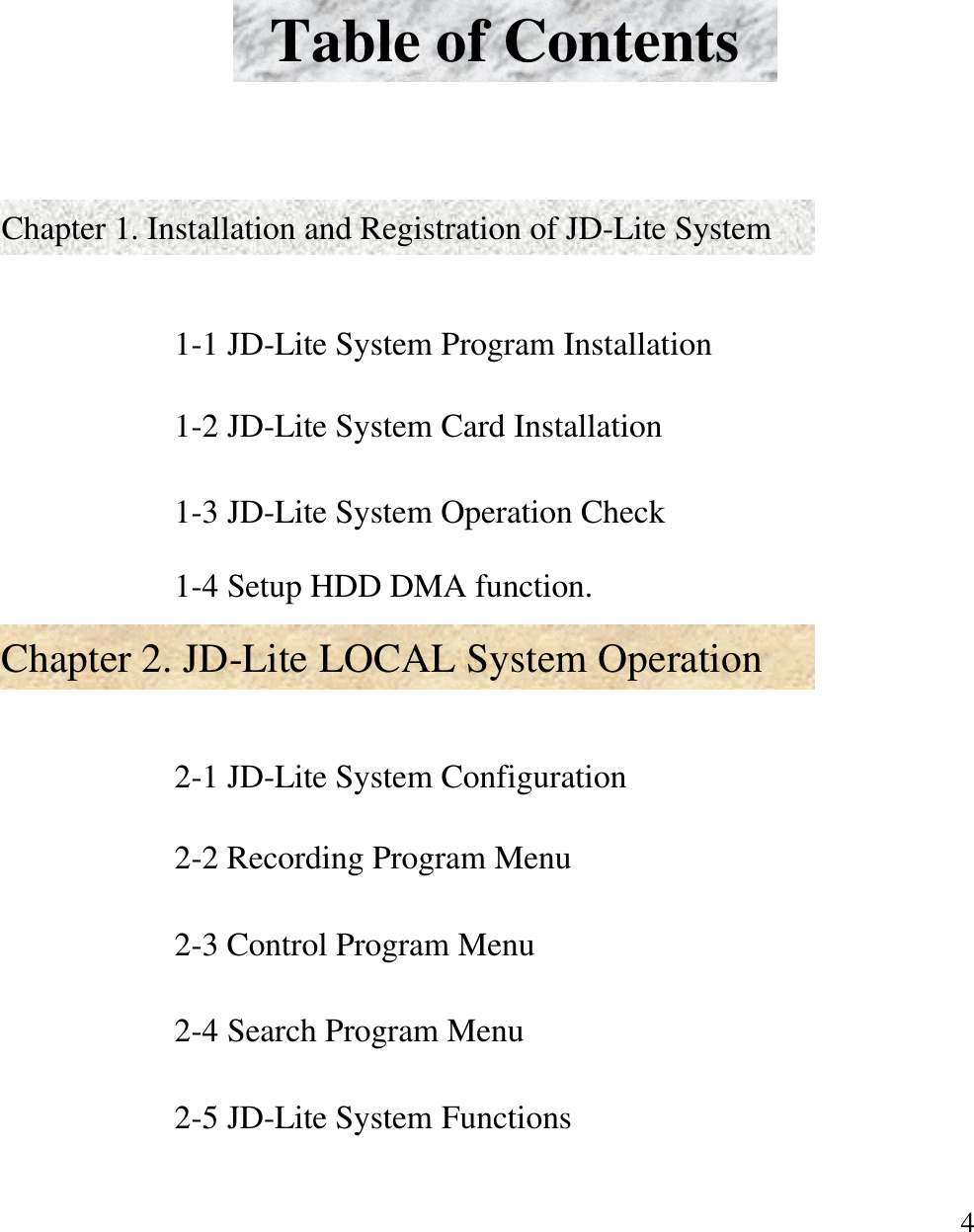
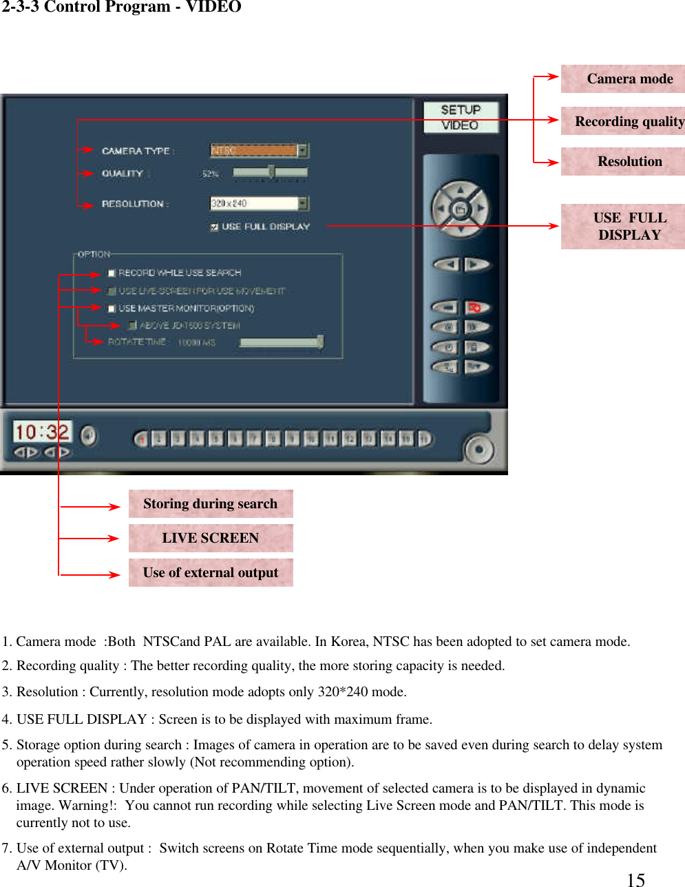
![46Q. Recording program produces not image, but black-colored screen. A. If an image is not produced, take action as follows:1. Check that you have selected ‘32 Bit (True Color) of color attributes of Display Registration (See Control Panel of Windows). 2. Check whether there is an error of ‘Video Capture64[BSR1000]’of ‘Sound Video and Game Controller’of systemmanager tab (See System Registration of control panel of Windows). 3. If same phenomenon may occur under a circumstance in the above, files of system controller is wrong. So, you areasked to procure a good program.](https://usermanual.wiki/Joongang-Telecom/JD-LITE/User-Guide-129940-Page-46.png)