Joongang Telecom JD-LITE DVRs Card User Manual Manual English 2
Joongang Telecom Co., Ltd. DVRs Card Manual English 2
users manual
1
DVR JD-Lite System
JD-Lite
User’s Manual
Thank you very much for your intelligent selection of DVR JD-Lite System, a digital video recorder system.
You are always assured of the best quality from us.
We expect your valuable patronage.
Yours faithfully,
Management and staffs of
Joongang Telecom
Joongang Telecom Co., Ltd

2
υCopyrights
No part of the software as well as this manual may be reproduced or transmitted in any form or
by any means for any purpose other than the purchaser’s personal use, without the express written
permission of Joongang Telecom Co., Ltd.
Such a violation may be punished.
Copyright, Joongang Telecom Co., Ltd. All rights reserved.
υUpgrade and After Sales Service
DVR System and its programs and information contained in this manual is subject to change without
notice to upgrade quality and functions, and does not represent a commitment on the part of Joongang
Telecom Company. You may get a copy of upgraded program and software from Joongang Telecom
Company.
υWarranty
1. You shall be given after sales service free of charge during ___ years after buying DVR JD-Lite.
2. You shall be responsible for failures of DVR JD-Lite caused by reasons in the below, and
accordingly shall pay our after sales service even during the warranty period:
1) Careless use and wrong operation;
2) Failures by repairing at your discretion, not by after sales service engineers and/or technicians
of Joongang Telecom.
3. You shall pay our after sales service after expiration of the warranty period.
4. For more information of after sales service, call over phone or visit DVR Business Division of
Joongang Telecom.
5. You are not assured of after sales service against failures of DVR JD-Lite caused by force
majeure.
Windows herein belongs to trademark of Microsoft Company.

3
υSpecifications
1. MAIN PROCESSOR : P-II500Mhz or above
2. MAIN BOARD : ATX Main Board
3. MAIN MEMORY : 64MByte or above
4. HARD DISK DRIVE : 15G Byte
5. VGA CARD : AGP 8 Mbytes or above(Voodoo,Savage chip series)
6. FLOPPY DISK DRIVE : 3.5 inch 1 piece
7. MOUSE : PS/2 MOUSE
8. KEYBOARD : 106 Key
9. D.V.R BOARD : JD-Lite PCI Card
-Camera Input : 4 Port 75 NTSC/PAL
υBefore calling After Sales Service department
At first, read this manual carefully to know whether you can repair DVR JD-Lite by yourself.
When you cannot do it, get in touch with DVR Business Division of Joongang Telecom to find out a
good solution after checking details of your problems.

4
Table of Contents
Chapter 1. Installation and Registration of JD-Lite System
Chapter 2. JD-Lite LOCAL System Operation
1-1 JD-Lite System Program Installation
1-2 JD-Lite System Card Installation
1-3 JD-Lite System Operation Check
2-2 Recording Program Menu
2-3 Control Program Menu
2-4 Search Program Menu
2-5 JD-Lite System Functions
2-1 JD-Lite System Configuration
1-4 Setup HDD DMA function.

5
Chapter 4. Question & Answer of JD-Lite System
3-1 Client Images Inquiry
3-2 Server Monitoring
3-3 Server Images Inquiry
Chapter 3. JD-Lire LAN/MODEM System Operation
3-4 JD-Lite LAN/MODEM System Operation

6
Chapter 1.
Installation and Registration of JD-Lite System
1-1 Installation of JD-Lite Program
υThis manual is based on Windows 98.
So, users of Windows 98 may understand JD-Lite program as well as this manual more easily.
1-1-1 Put No. 1 diskette of JD-Lite
to run program.
1-1-2 Click “Next”on ‘1-1-1’screen
to install the system.
1-1-3 When you finish the installation, icon
of JD-Lite shall be registered on Start
menu screen of Windows 98.
1-1-4 JD-Lite directory shall be automatically
made on your C drive.
JD-Lite
JD-LiteJD-Lite
JD-Lite
7
1-2-1 JD-Lite board is a kind of P&P board of PCI way (There exists no jumper). Turn your
computer OFF to open main body. Then, find out empty PCI slot and put the board into it.
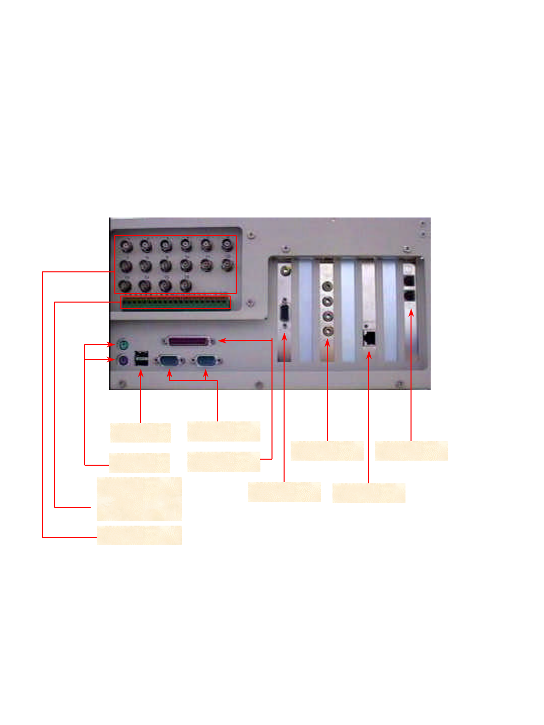
1-2 JD-Lite System Card Installation
1-2-2 Close the main body. Connect BNC cables to necessary ports among 16 camera ports in the
rear of main body. You also connect BNC cable at opposite side to camera.
USB port
P/S 2 port
Serial port
Parallel port
Video port
JD-Lite port
UTP port
Modem port
External output
system and
sensor port
Camera port
1. Camera port : Connect BNC cable of No. 1 ~4 camera. Each port has its own number.
2. External output system and Sensor port : Connect not only cables of No. 1 ~ 4 sensor, but also four (No. 17~20)
of external output system. Each port has its own number.
3. JD-Lite port : Connect four cameras. The port is used when camera port is not used.
4. Serial port : Make use of serial port No. 1 to use Pan/Tilt.
5. Other ports : When you make use of monitor, keyboard, mouse, LAN, modem and so on, you may use other ports.
8
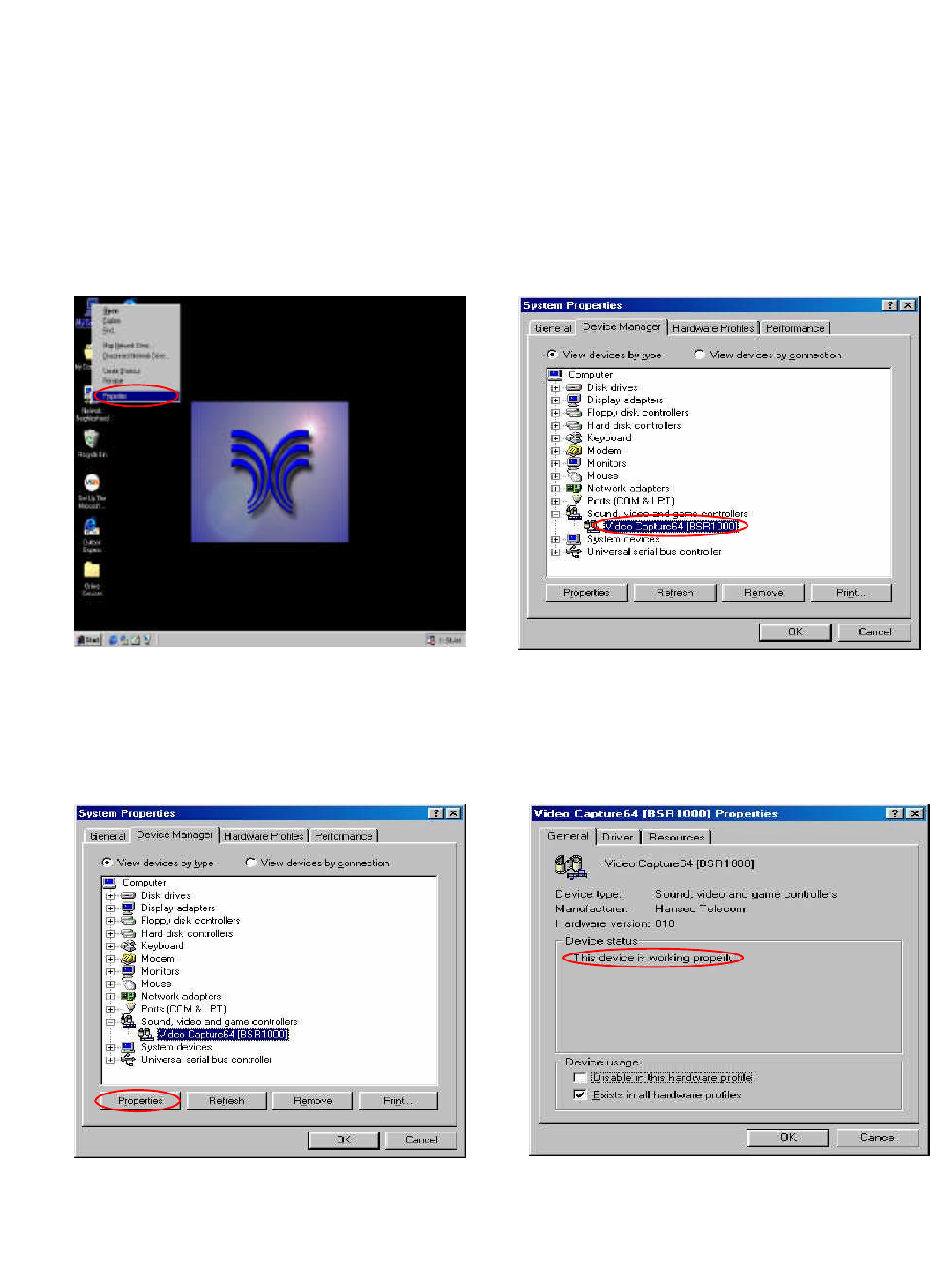
1-3-3 Select ‘Controller’, and then
click Registration Information.
1-3-4 Make Registration Information
window become active. Then,
a message of ‘The system runs
correctly’indicates normal installation
of the system.
1-3 JD-Lite System Operation Check
1-3-1 At first, click My Computer icon, and
then click right-hand button of mouse to
display menu in the below. Then, click
registration information.
1-3-2 Make System Registration Information
window become active. Check that
a controller named ‘Video
Capture64[BSR1000]’has been registered in
‘Sound, Video and Game Controller’.
9
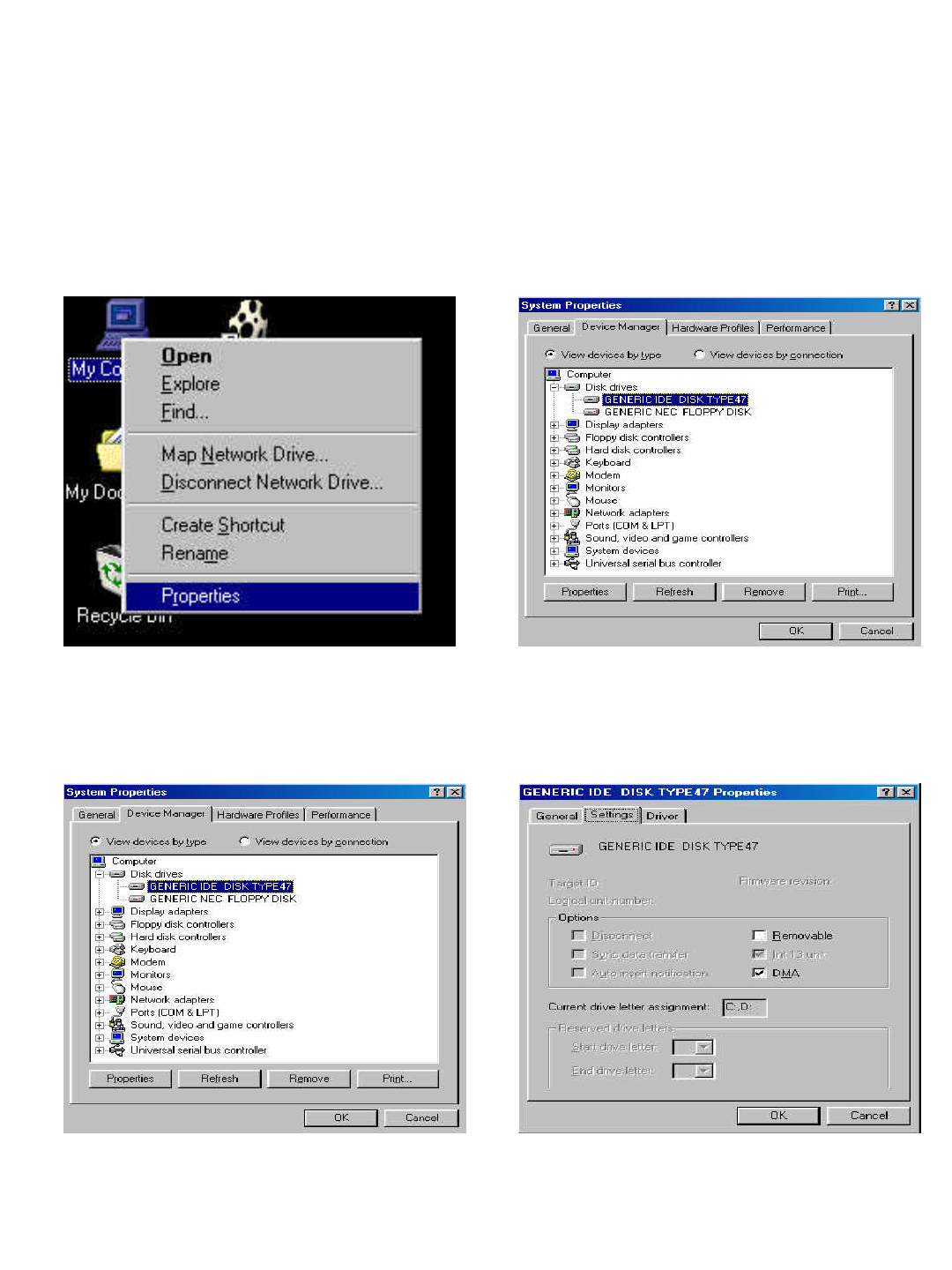
1-4-3 Select `GENERIC IDE DISK TYPE`,
Then Click [Properties]
1-3-4 Click [Settings],select DMA.
Then reboot the system to complete set
-up DMA function.
1-4 Set-up HDD DMA Function
1-4-1 At first, click My Computer icon, and
then click right-hand button of mouse to
display menu in the below. Then, click
registration information.
1-4-2 After window become active,
Click Disk Drives.
10
Chapter 2.
JD-Lite Local System Operation
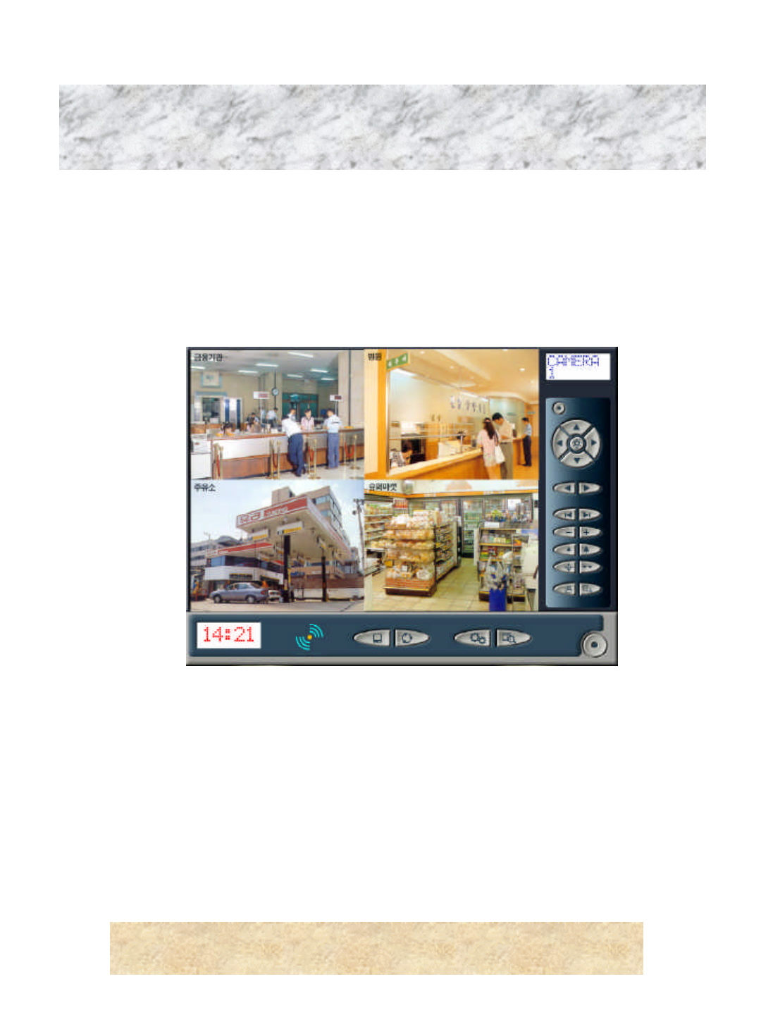
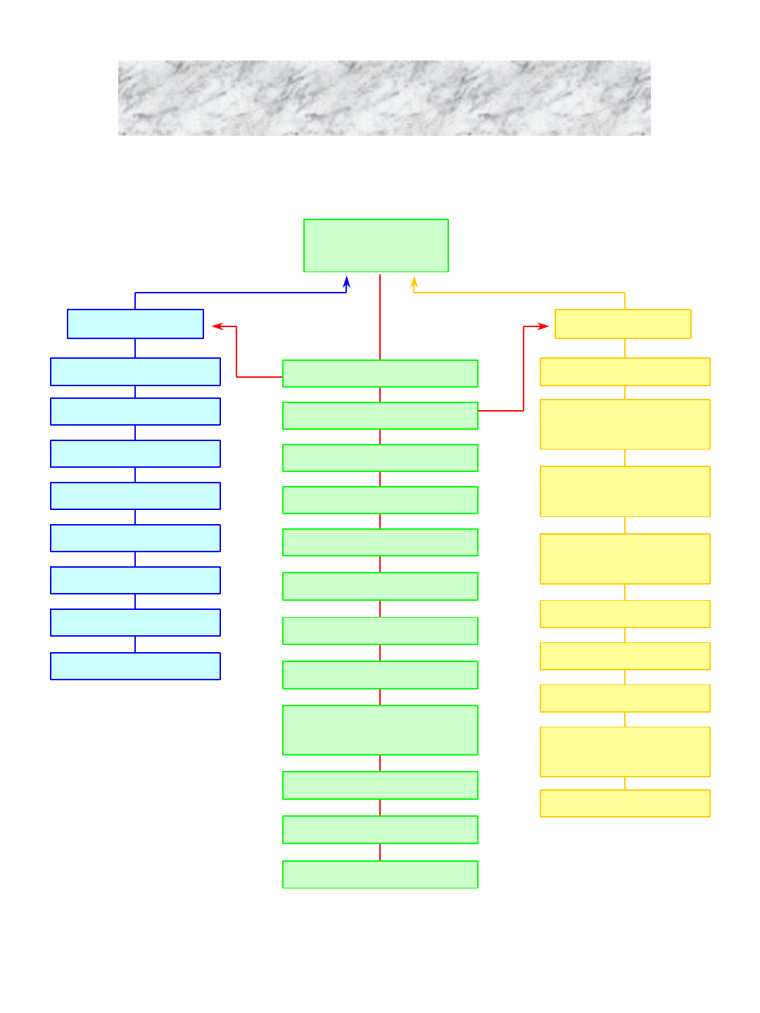
Recording
program
Control program Search program
Pan/Tilt mode ON/OFF
Pan/Tilt mode ON/OFF
Direction (up/down, right/left)
Camera selection
Movement to right-hand &
left-hand limit
Scaling
Wide /Narrow
Auto adjustment /Rotation
Full Screen
Rotation (for monitoring)
Setup Mode
Search Mode
Video
Speed
Amount
Image (color)
Reserved
Password
Motion
Camera selection (No. 1~4)
Play of saved images
Selection of front and
rear camera
Movement of front and
rear frame
1 minute before &
after search
Movement to First and Last
Backup of floppy disk
Update of saved screen
Display of hard disk
information
Printout
2-1 JD-Lite System Configuration
11
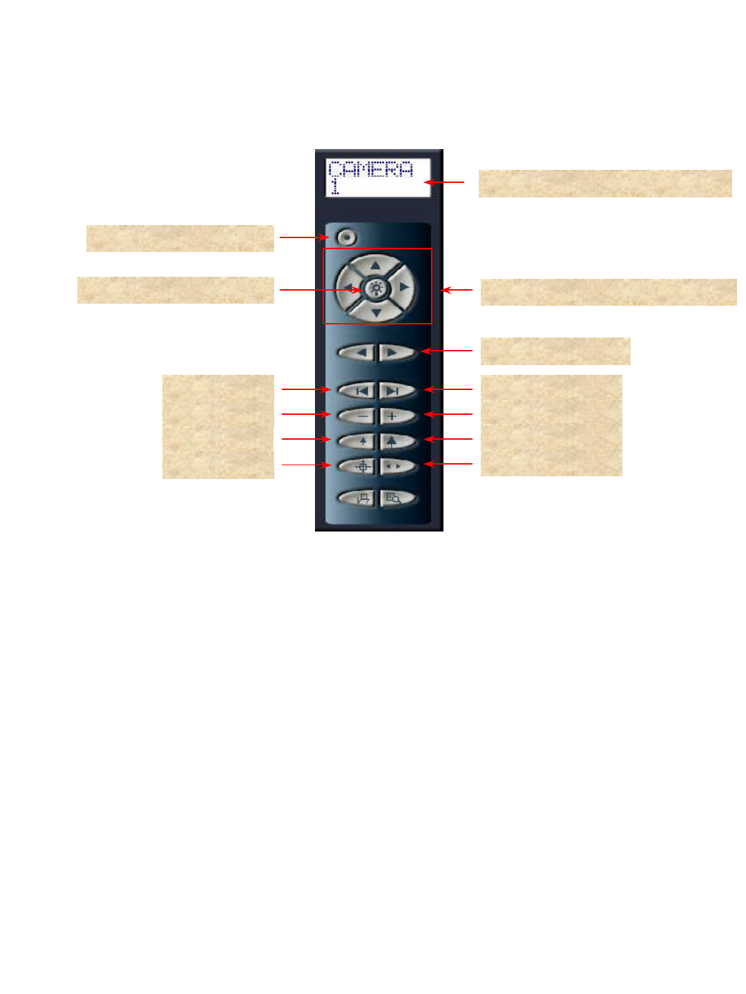
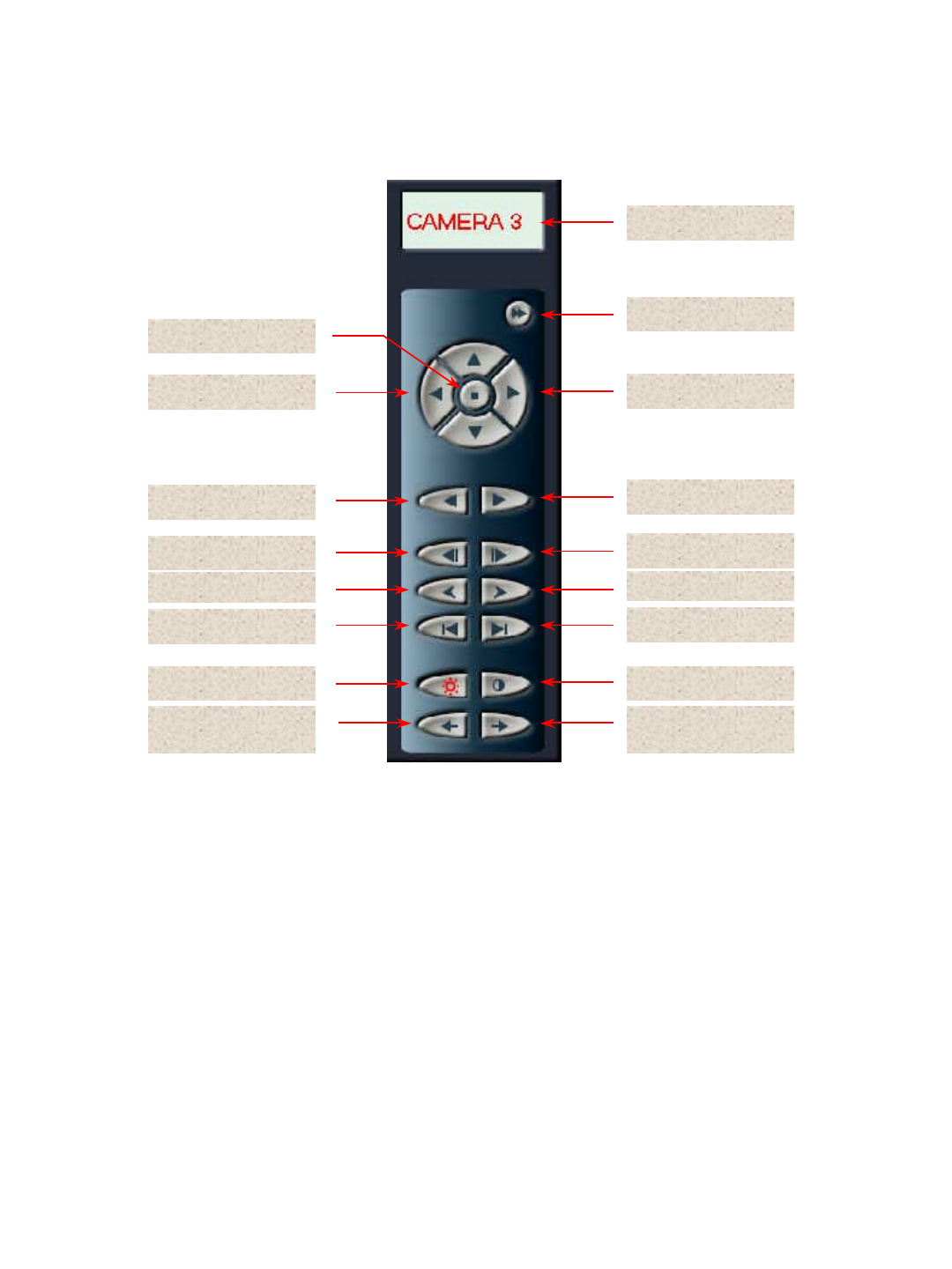
Camera display window for PAN/TILT
Direction control (up/down & right/left)
PAN/TILT MODE ON/OFF
PAN/TILT POWER ON/OFF
Selection of Camera
RIGHT LIMIT
ZOOM OUT
WIDE
AUTO ROTATION
ZOOM IN
LEFT LIMIT
TELE
AUTO FOCUS
2. PAN/TILT MODE ON/OFF : ON/OFF of control panel
1. Camera display window for PAN/TILT: Current camera is to be displayed.
4. Direction control : Adjust camera up/down and right/left.
5. Selection of camera : Select a camera.
6. LEFT LIMIT : Move camera focus to left end.
7. RIGHT LIMIT : Move camera focus to right end.
8. ZOOM IN : Make camera focus run Zoom In.
9. ZOOM OUT : Make camera focus run Zoom Out.
10. TELE : Make camera focus become narrow.
11. WIDE : Make camera focus become wide.
12. AUTO FOCUS : Adjust camera focus automatically.
13. AUTO ROTATION : Rotate camera automatically.
3. PAN/TILT POWER ON/OFF : ON/OFF of power system of PAN/TILT
2-2-1 Pan/Tilt Control Panel of Recording Program
2-2 Recording Program Menu
12
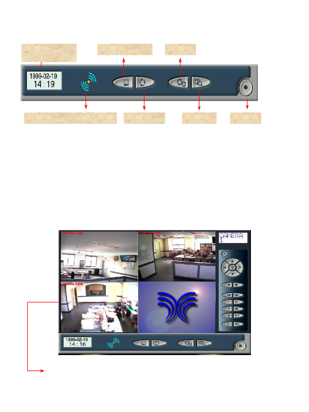
(Display not only name of camera but also movement sensing.)
Camera 3 indicates given name of camera by each location, while (M) does
movement of each camera (Motion function).
2-2-2 Major Screens of Recording Program
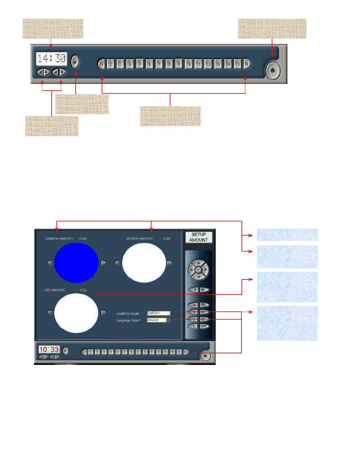
2-2-2 Main Control Panel of Recording Program
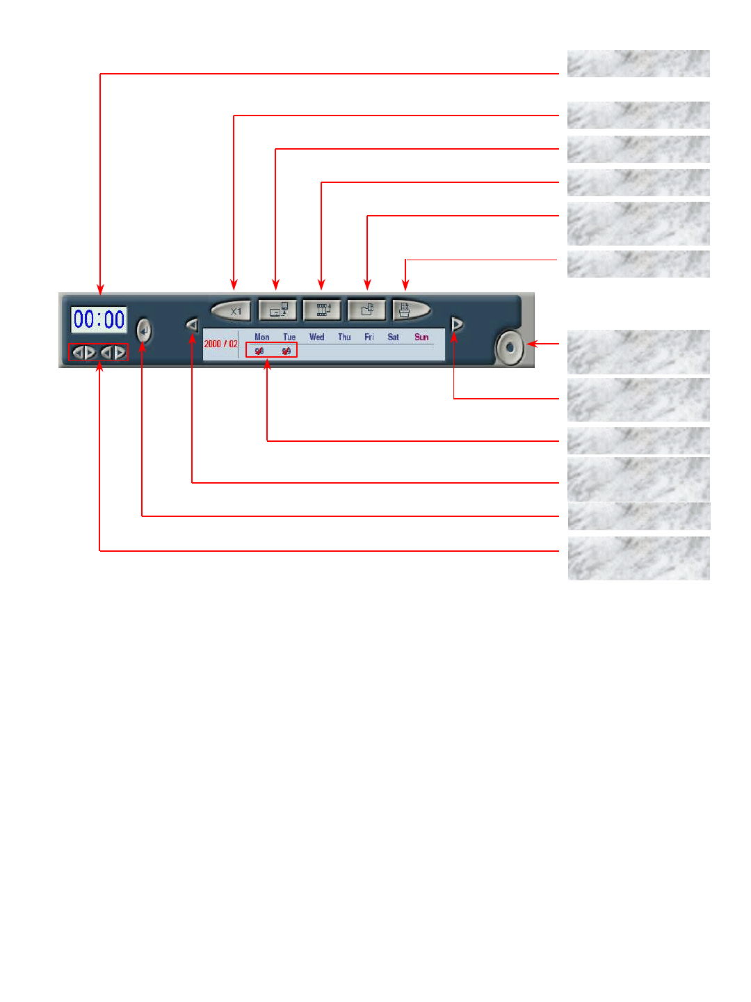
Date & time
display FULL SCREEN SETUP
Display of system operation status ROTATION SEARCH POWER
1. Date and time display : Display current date and time.
2. FULL SCREEN : Hide Menu window, and switch monitoring screen to maximum image screen.
3. SETUP : Switch to Set Up mode to set system.
4. Display of system operation status: Movement of blue-colored waveform indicates “Under full recording”, while
that of yellow-colored waveform does “Motion Perceive Recording”.
5. ROTATION : Display only one of selected camera on overall monitoring screen intensively.
6. SEARCH : Switch to Search mode to run recording screen search, backup, output and so on.
7. POWER : Push Power button to let Display Level reach 100%, and release the button to turn the system OFF.
13
2-3 Control Program Menu
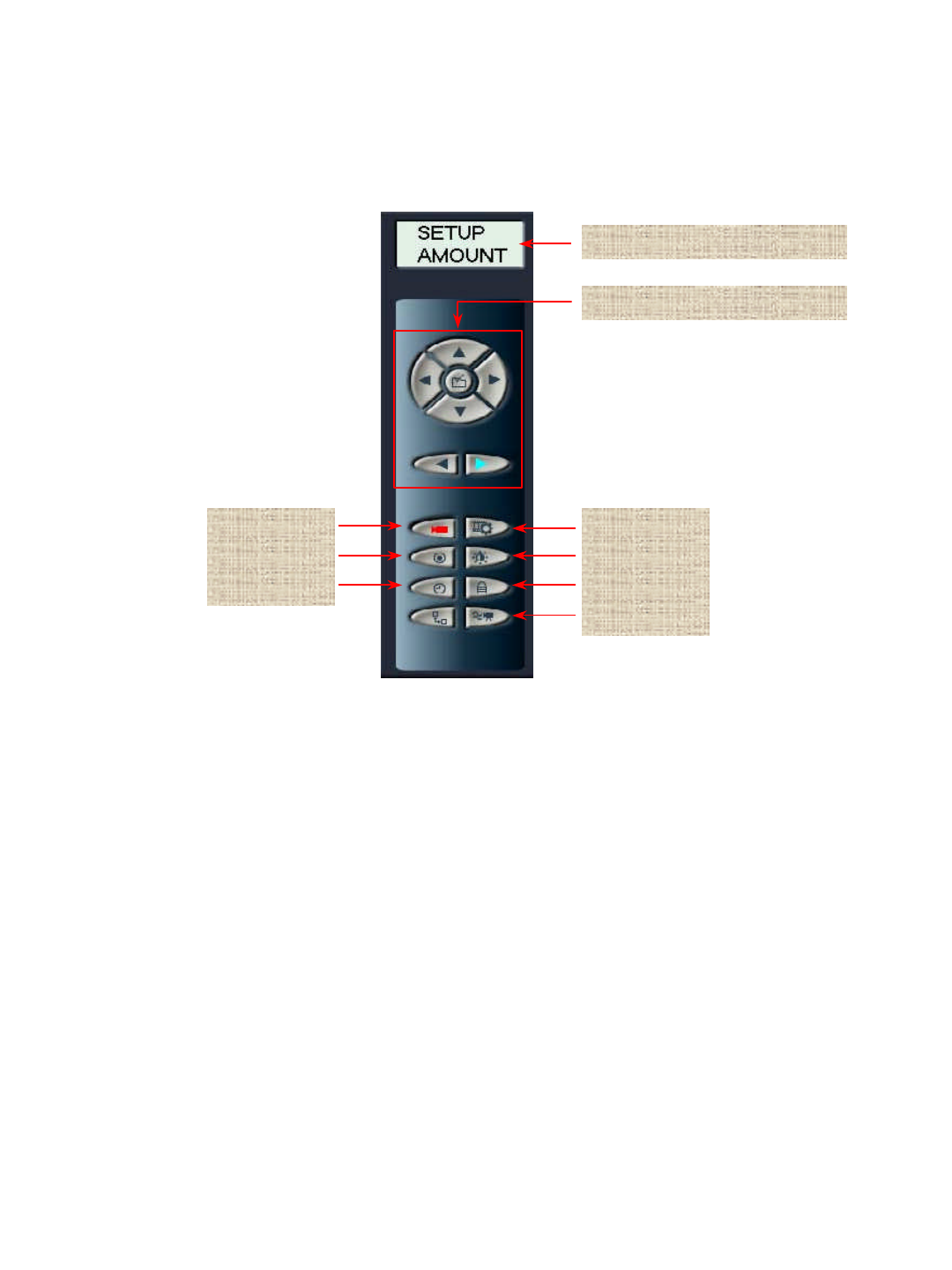
2-3-1 Control Panel of Control Program
MODE and Sub Menu Display
Selection button of Sub Menu
AMOUNT
SPEED
RESERVED
VIDEO
IMAGE
PASSWORD
MOTION
1. MODE and Sub Menu Display : Display not only current mode but also sub menu of selected setup.
2. Selection button of sub menu: The button selects sub menu in the below in sequence. It also selects
sub menu directly.
3. AMOUNT : Switch to sub menu that can adjust number of camera, sensor and external output system.
4. VIDEO : Switch to sub menu that can select recording option of both image signal and video.
5. SPEED : Switch to sub menu that can adjust recording speed.
6. IMAGE : Switch to sub menu that can adjust contrast and brightness of output screen.
7. RESERVED : Switch to sub menu that reserves recording.
8. PASSWORD : Switch to sub menu that changes password of manager.
9. MOTION : Switch to sub menu that sets motion monitoring.
14
Setting time
display Recording program
switching
Application of
setting time Camera selection
button
1. Setting time display : Display current setting time.
2. Current time setting : Change time at option, while running system.
3. Application of setting time : After finishing time setting, the set time is to be applied to system.
4. Recording program switching : Return to recording program.
5. Camera selection button : The button selects camera in the case of change of camera name, setting of images
and motion, and other setting of each camera.
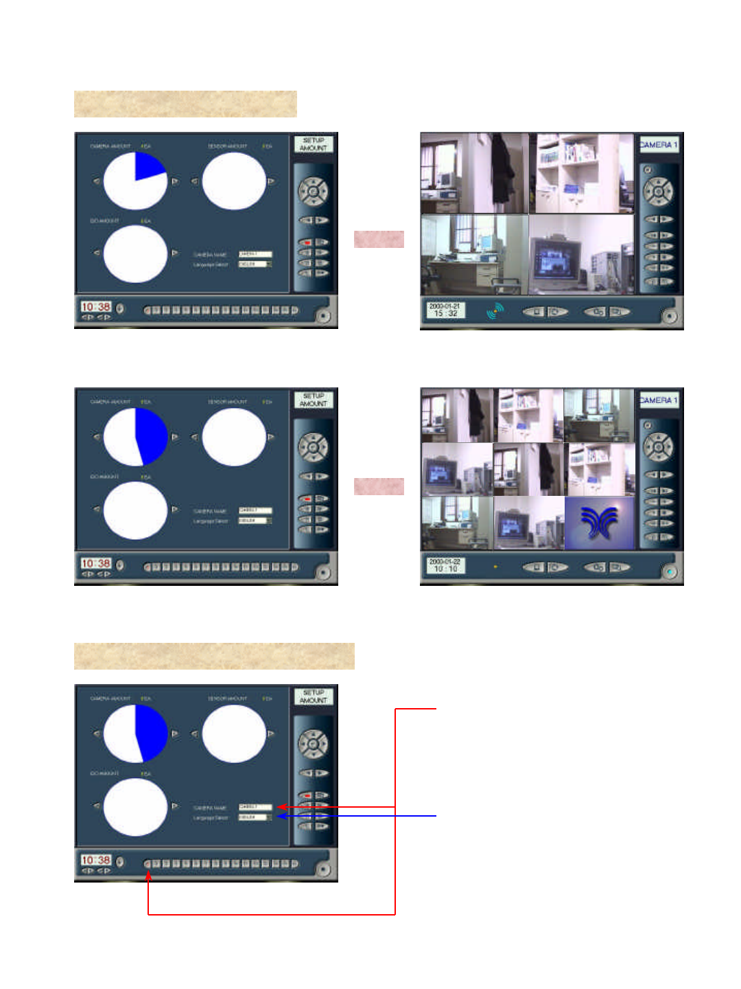
2. Name of camera : Click “Select”of camera at bottom to change name of installed camera, and then input
data with keyboard (Both Korean language and English may be accepted.).
Number of sensor
(Not this function work at
JD-Lite)
Number of camera
Number of external
output
(Not this function work at
JD-Lite)
1. Number of camera : Set number of camera by using Right/Left arrow.
2-3-2 Control program -AMOUNT
Camera name and
Korean
language/English
selection
Setting of
current time
15
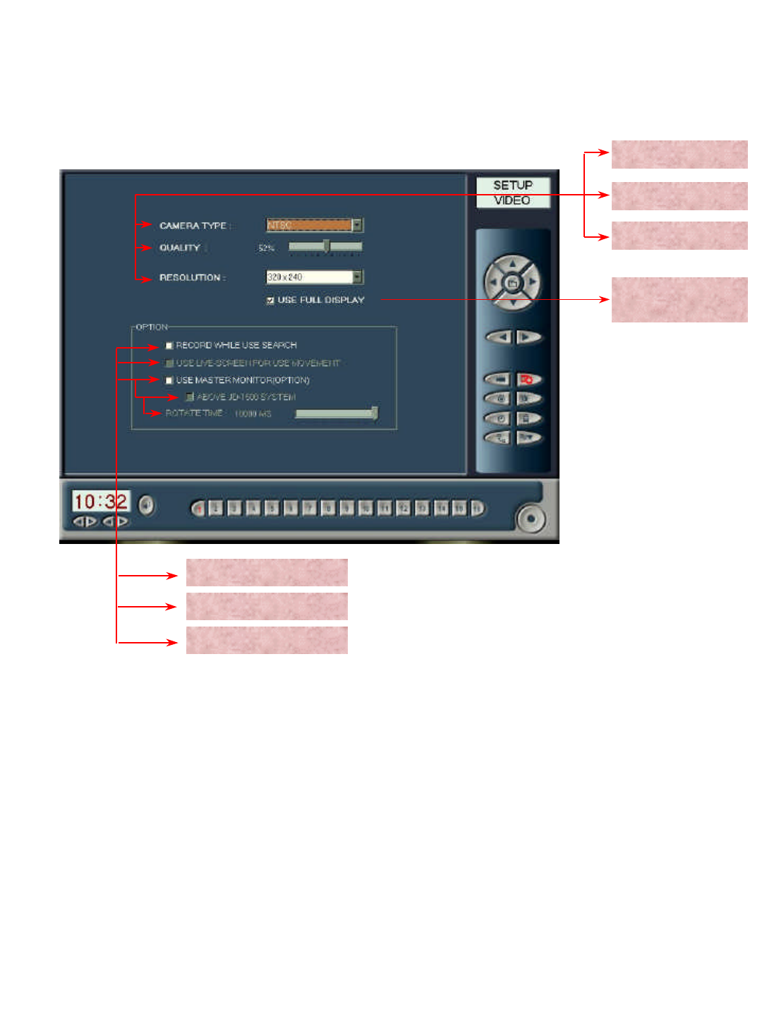
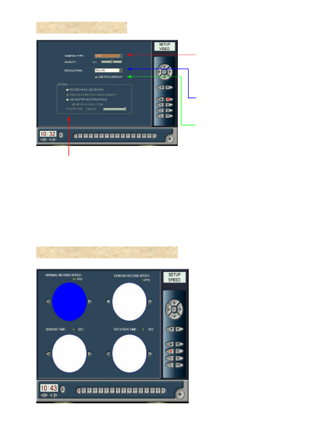
2-3-3 Control Program -VIDEO
Camera mode
Recording quality
Resolution
Use of external output
LIVE SCREEN
Storing during search
1. Camera mode :Both NTSCand PAL are available. In Korea, NTSC has been adopted to set camera mode.
2. Recording quality : The better recording quality, the more storing capacity is needed.
3. Resolution : Currently, resolution mode adopts only 320*240 mode.
5. Storage option during search : Images of camera in operation are to be saved even during search to delay system
operation speed rather slowly (Not recommending option).
6. LIVE SCREEN : Under operation of PAN/TILT, movement of selected camera is to be displayed in dynamic
image. Warning!: You cannot run recording while selecting Live Screen mode and PAN/TILT. This mode is
currently not to use.
7. Use of external output : Switch screens on Rotate Time mode sequentially, when you make use of independent
A/V Monitor (TV).
USE FULL
DISPLAY
4. USE FULL DISPLAY : Screen is to be displayed with maximum frame.
16
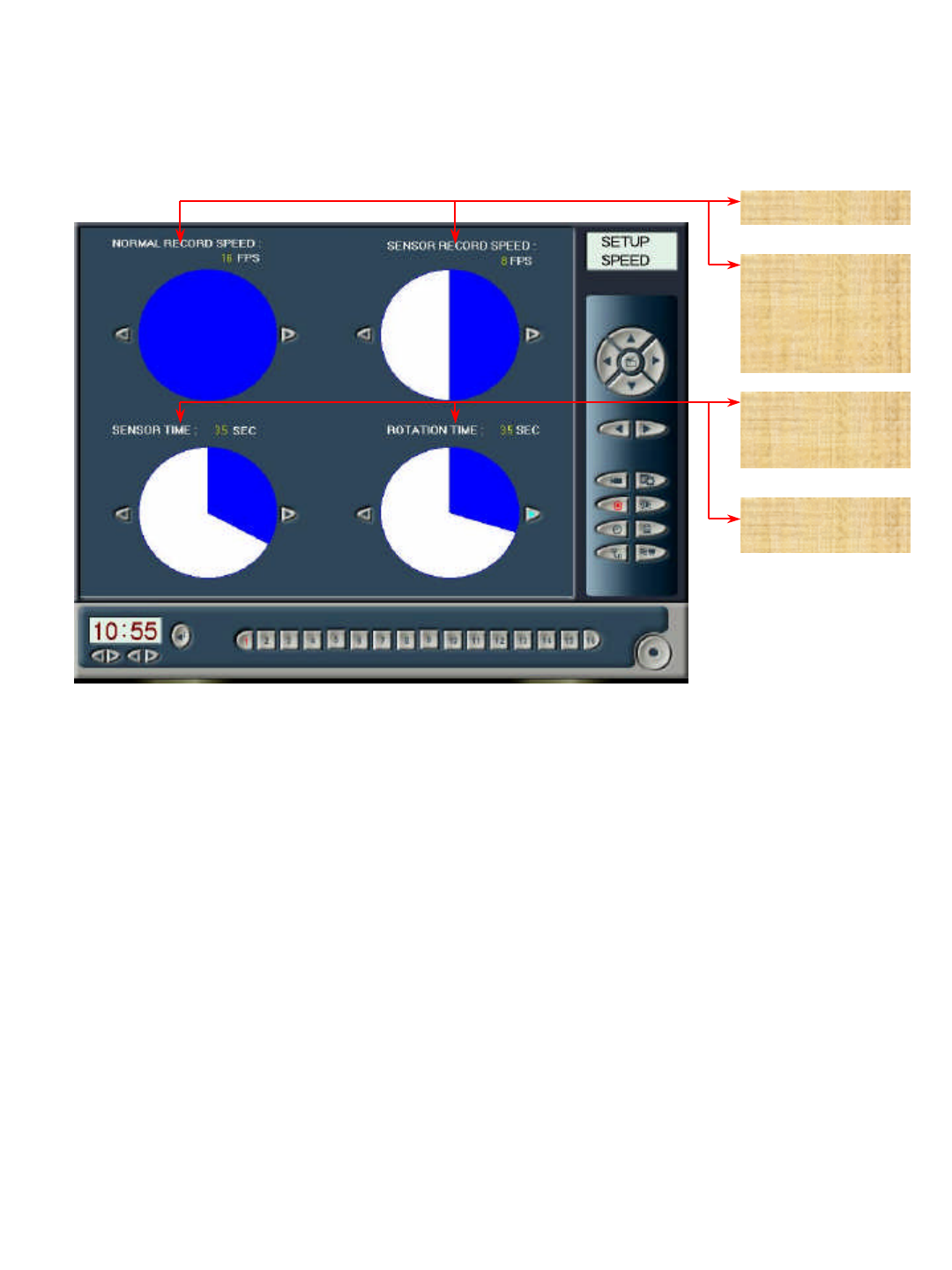
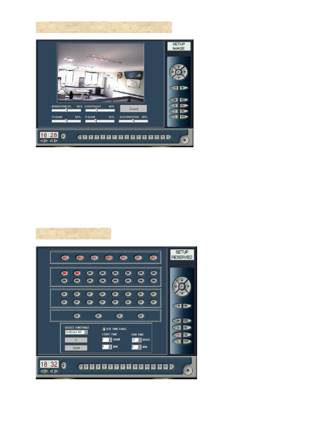
2-3-4 Control Program -SPEED
Recording frame
Recording frame
setting in the use
of sensor
(Not this function work
at JD-Lite)
SENSOR TIME
(Not this function work
at JD-Lite)
ROTATION
TIME
1. Recording frame : Adjust recording speed. ( 1-40 FRAME/SEC )
2. ROTATION TIME : When you want to monitor from monitor of main body not by divided screens, by auto
selector, you may set time interval for screen switching.
17
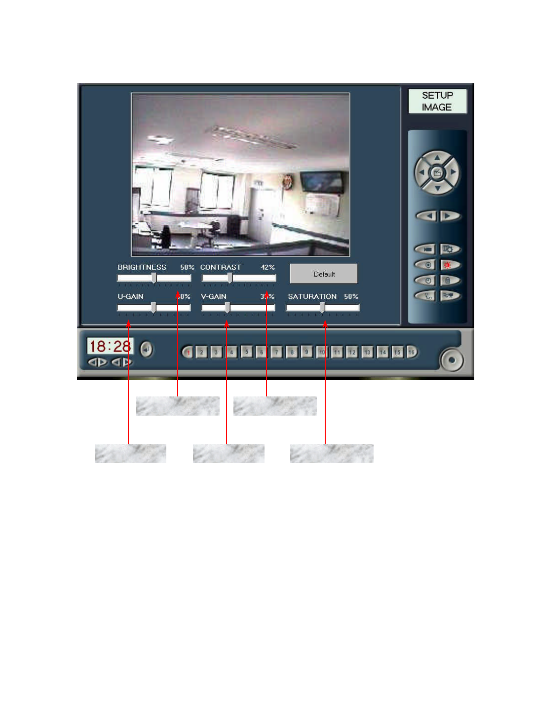
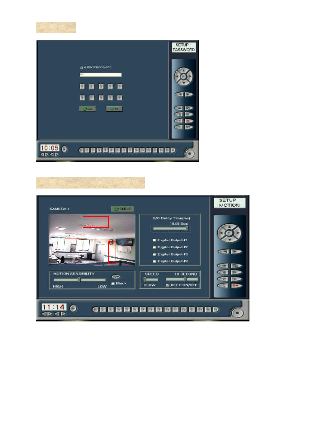
2-3-5 Control Program -IMAGE
BRIGHTNESS CONTRAST
U-GAIN SATURATIONV-GAIN
1. BRIGHTNESS : Set monitor mode as well as brightness of recording images.
2. CONTRAST : Set monitor mode as well as contact of recording images.
3. U-GAIN : Select red color of 3 primary colors.
4. V-GAIN : Select green color of 3 primary colors.
5. SATURATION : Select blue color of 3 primary colors.
18
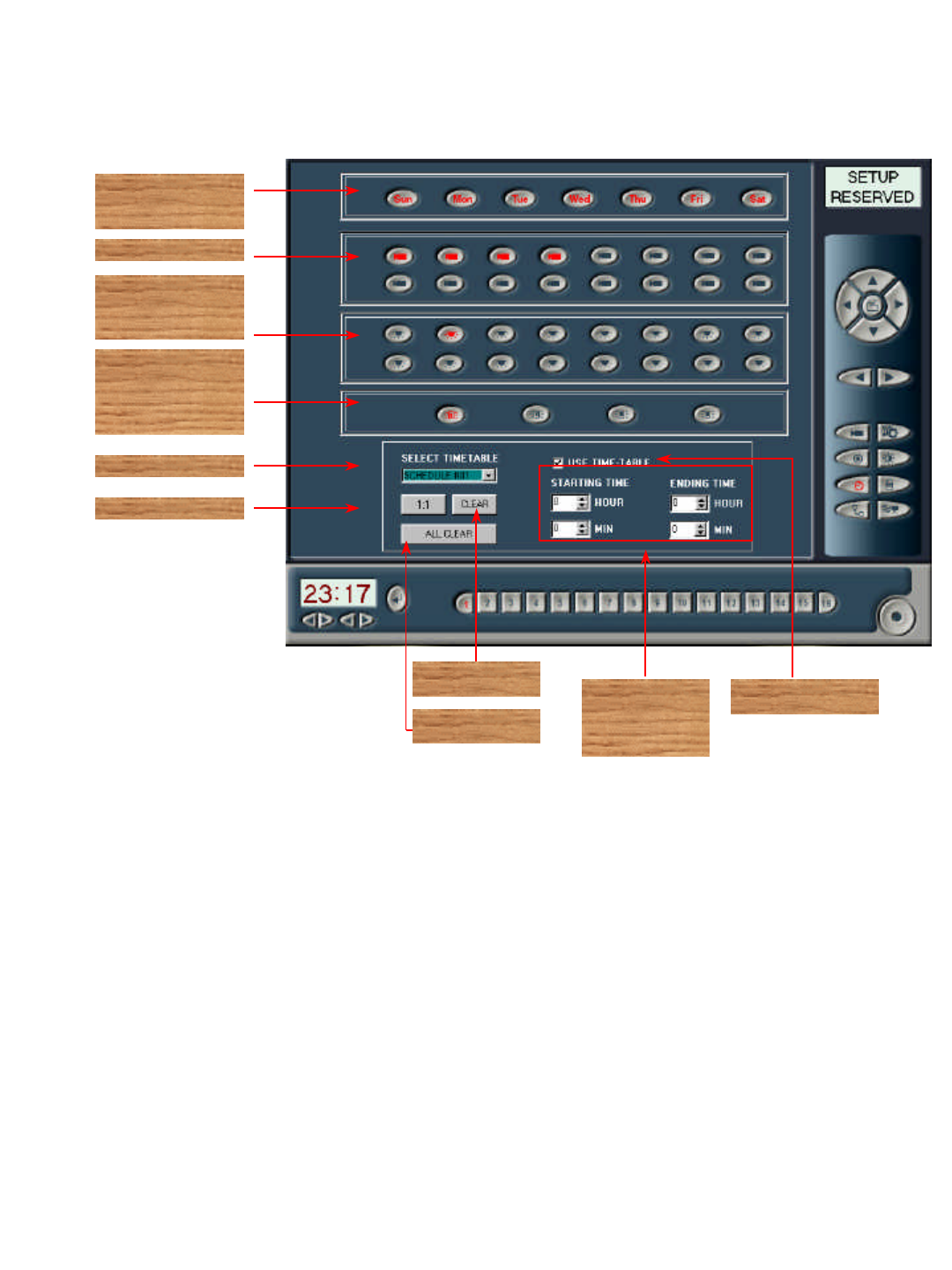
2-3-6 Control Program -RESERVED
Recording day
of the week
Recording camera
SENSOR
(Not this function work
at JD-Lite)
External output
system
(Not this function work
at JD-Lite)
Time Table
1:1
Setting of
hour &
minute
Use Time Table
1. Recording day of the week : Select recording day of the week.
2. Recording camera : Select recording camera among installed cameras.
3. SENSOR : Select sensor for operation among installed sensors. (Not this function work at JD-Lite)
4. External output system : Select a system for operation among installed external output systems. (Not this function
work at JD-Lite)
5. Time Table : Select reserved recording schedule, which you want.
6. 1:1 : Reserve each one set of camera and sensor to one to one of ratio among 16kinds of schedules.
7. CLEAR : Initialize status of reservation.
8. Setting of time and minute : Set both start time and finish time of reserved recording.
9. Use Time Table : Check use of reservation recording mode. When Use Time Table is not selected, you can do
monitoring by only screen, but cannot save images.
Clear
All Clear
10. Use Time-table select using time table or not(If not selected,display on screen only,does not recording
19
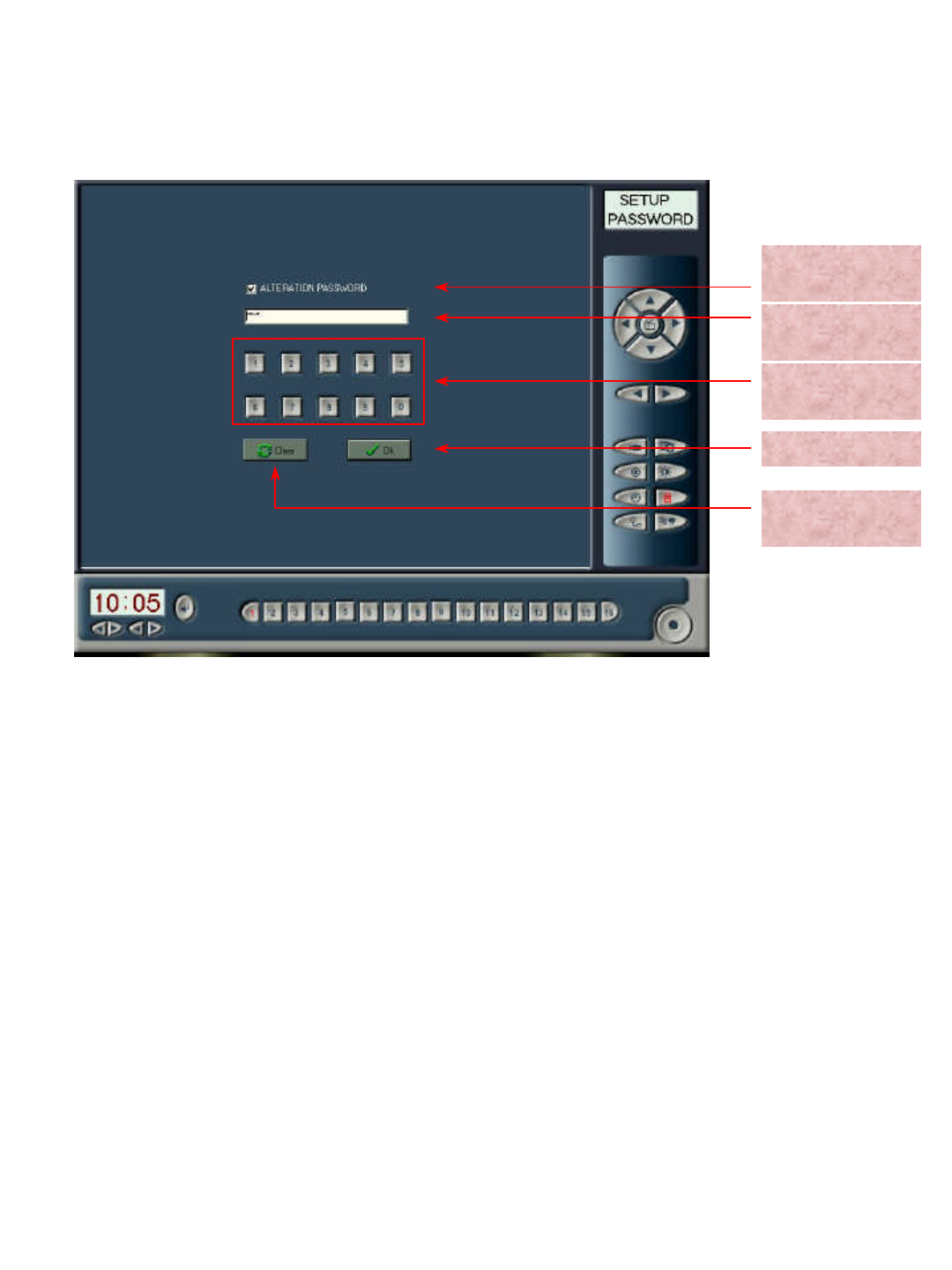
2-3-7 Control Program -Password
ALTERATION
PASSWORD
Input of
password
Password input
button
Input cancel
Application of
password
1. ALTERATION PASSWORD : Check use of password.
2. Input of password : Display input password in type of box.
(Input password is to be displayed in symbol of *.)
3. Input button of password : The button can input a password. Note: Keyboard cannot input a password.
4. Input cancel : Resave original status by clicking Input Cancel.
5. Application of password : Apply input password to your computer.
20
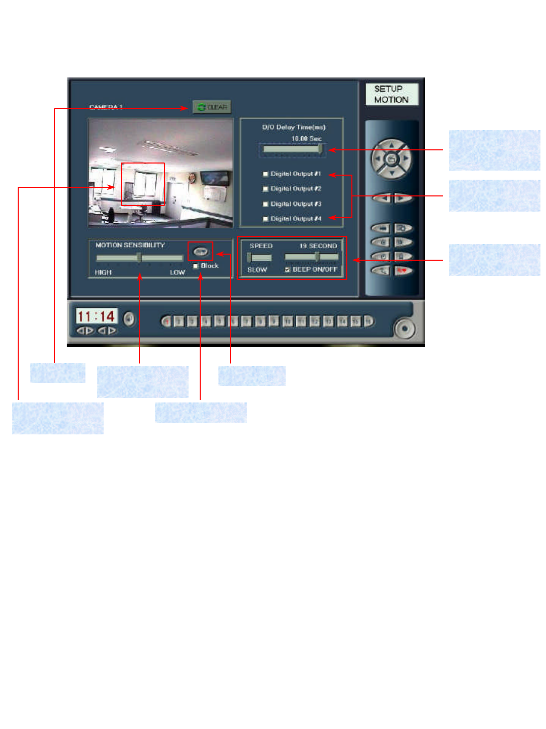
2-3-8 Control Program -MOTION
Delay time of
external output
signal
Use of external
output signal
Alarm speed &
delay time
MotionMotion
sensibility
Motion block
6. Delay time of external output signal : Select delay time of signal of external output system.
7. Use of external output signal : Select Use of signal of external output system.
8. Alarm speed and delay time : Select Use of alarm, and speed and time of alarm when monitoring motion.
4. Motion block : Select of Use of Motion Block. Select this mode to set partial block. Otherwise, do not select this
mode to monitor all of screens.
3. Motion : Select Use of Motion. Select this mode to monitor all of screens.
5. Motion sensibility : Select degree of motion sensibility.
CREAR
Block setting
display
1. Block setting display : Select a camera by using camera selection button at bottom. Then, place mouse pointer at
the place requiring intensive monitoring, and then click left-hand button of mouse. Click right-hand button of
mouse to release partially.
2. CLEAR : Initialize block.
21
2-4 Search Program Menu
2-4-1 Control Panel of Search Program
1. Camera display : Name of camera that currently researches
2. High speed play : Play images in high speed.
3. Play : Play images.
4. Reverse play : Play images in reverse direction.
5. Pause : Pause movement of images while playing.
6. Previous camera : A camera before currently selected one.
7. Next camera : A camera next to currently selected one.
8. Previous frame : Search of images1frame ahead
9. Next frame : Search of 1frame behind.
10. 1minute before search : Search 1 minute before image.
11. 1minute after search : Search 1minute after image.
12. Movement to First : Move to first image
13. Movement to Last : Move to last image.
14. Brightness : Adjust brightness of image.
15. Contrast : Adjust contrast of image.
High speed play
Play
Next camera
Next frame
Search 1 minute later
Movement to Last
Contrast
Brightness/Contrast
Up
Brightness/Contrast
Down
Brightness
Movement to First
Search 1 minute before
Previous frame
Previous camera
Reverse play
Pause
Camera display
16. Brightness/Contrast Down : Decrease brightness and contrast.
17. Brightness/Contrast Up : Increase brightness and contrast.
22
Search time display
Search scale
FDD backup
Image update
DISK information
display
Printout
Switching to main
window
Search time
(hour, minute)
1 week later storing
date
Date of image
1. Search time display : Current research time of image is to be displayed.
2. Search time (hour, minute) : Search time in hour and/or minute is to be displayed.
3. Input of setting time : Input time is to be displayed.
1 week before
storing date
Setting time
4. Search scale : Adjust scale of image to search (maximum: 3 times).
5. FDD backup : Save currently searching images in a diskette.
6. Image update : Update images saved during search.
7. DISK information display : Display current capacity of hard disk.
8. Printout : Printout images with printer.
9. 1 week before storing date : Search an image that was saved 1 week before.
10. 1week later storing date : Search an image that is saved 1 week later.
11. Date of image : Display date when an image exists.
12. Switching to main window : Switch an image to main window.
23
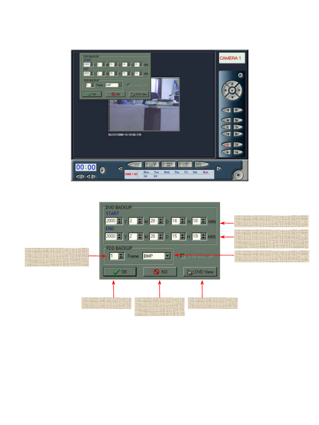
2-4-2 Search Program -BACKUP
N FRAME BACKUP
from current image
BACKUP Start BACKUP
Cancel
BACKUP image type
DVD VIEW
DVD backup start time
DVD backup
completion time
1. DVD backup start time : Input start time of an image that is to be saved in DVD Disk.
2. DVD backup completion time : Input completion time of an image that is to be saved in DVD Disk.
24
3. FRAME BACKUP from current image : save necessary frame in floppy disk from currently searching images.
4. BACKUP image type : Display image type, for example, BMP and JPG, to be saved.
5. BACKUP start : Start backup.
6. BACKUP cancel : Cancel backup and return to search program.
7. DVD VIEW : Search or delete images saved in DVD DISK.
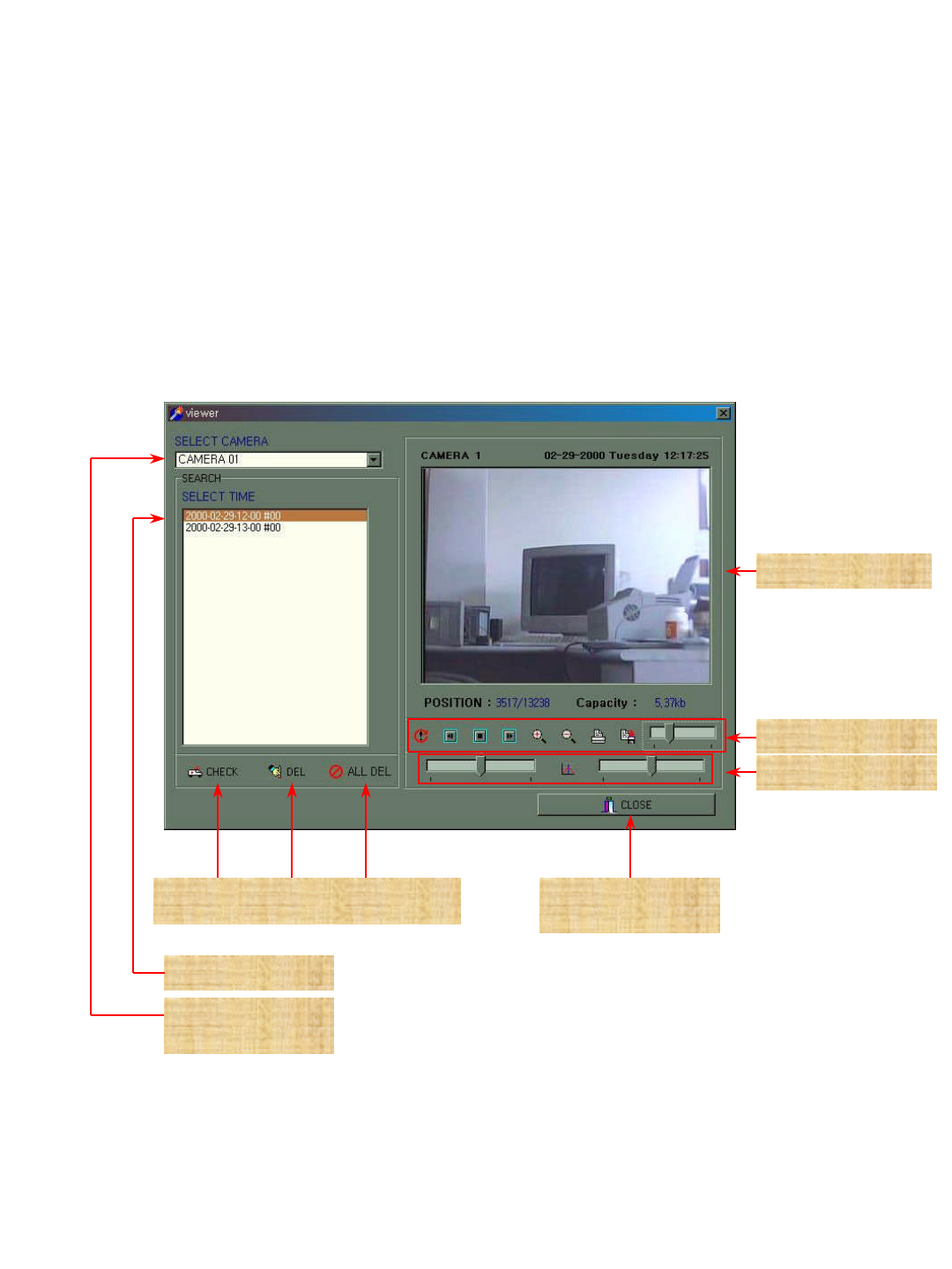
All of images
delete
Error
Check
Selection of images
Selection of
camera
DVD Viewer
completion
Brightness/Contrast
DVD control panel
Screen display
7-1. ERROR CHECK : Inspect files saved in DVD Disk.
7-2. Image delete : Delete an image that is selected at search box.
Image
delete
25
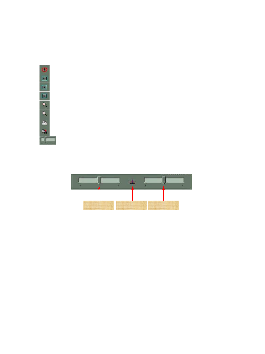
7-5. DVD control panel : Play, delete, output and save images.
A. REFRESH : Lists of up-to-date images
B. BACK : Move to 1 Frame previous image.
C. PLAY / BACK PLAY : Play images, or play in reverse direction from end of images.
D. FORWARD : Move to 1 Frame behind image.
E. ZOOM IN : Expand size of current image.
F. ORIGINAL : Reduce size of image to that of before Zoom In.
G. PRINT : Printout current image with printer.
H. SAVE AS : Save current image in other file name.
I. Play Scroll : Play images by using Scroll Bar.
7-6. Brightness / Contrast : Adjust brightness and/or contrast of current image.
Brightness Default Contrast
7-3. All of images delete : Delete all of images that are saved at search box.
7-4. Screen display : Search an image that is selected at search box.
8. DVD Viewer Completion : Complete DVD search, and switch to search program.
26
2-4-3 Search Program -DISK INFO
HDD DISK
information
Image delete
Return to search
program
1. HDD DISK information : Display information on hard disk to show total capacity as well as current occupancy
by figure and graphs.
2. Image delete : Delete all of saved images.
3. Return to search program : Close hard disk information window, and return to search program.
27
2-4-4 Search Program -PRINT
Printer cancel
Printer set up
N FRAME printout
Printer printout
Printout image name
1. Printout image name : Nominate name of printout image.
2. N FRAME printout : Input number of frame to printout from current image.
3. Printer printout : Printout images with printer.
4. Printer set up : Switch to printer set up window to printout details of printer of current system.
5. Printer cancel : Cancel printing and return to search program.
28
2-5 JD-Lite System Functions
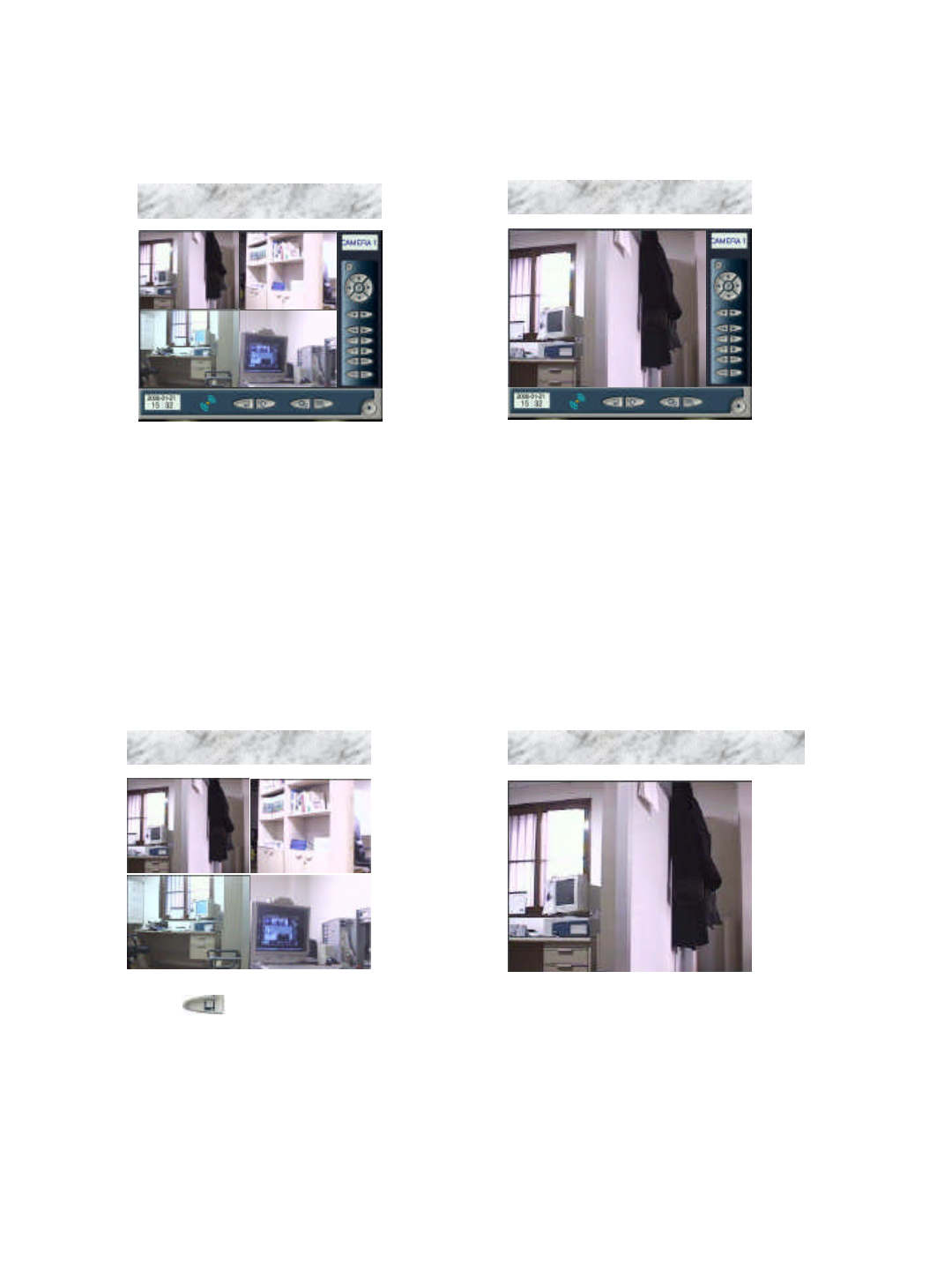
2-5-1 Recording program
Save images in recording
program screen.
1. Common mode
Click left-hand button of mouse
to switch four cameras to overall
screen and show images. You
can set the switching time by
using speed set up of control
program.
2. Auto switch mode
Click button to switch
to overall screen mode. On the
other hand, click right-hand
button to return to Common
Mode.
3. Overall screen mode 4. Overall screen auto switch mode
Click left-hand button of mouse at
overall screen mode to switch to
overall screen auto switch mode. On
the other hand, click right-hand
button to return to Common Mode.
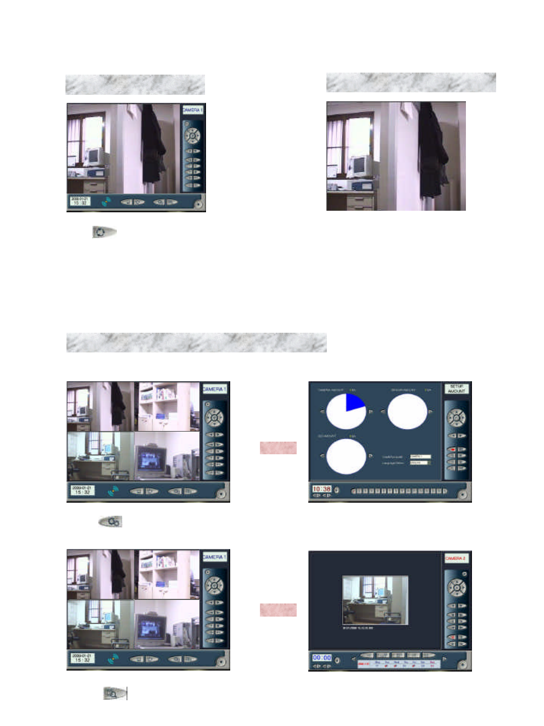
29
Click button to switch to
Monitoring Screen mode to fix
Auto Switch mode at a specific
screen.
5. Monitoring screen mode 6. Overall screen monitoring mode
Click right-hand button of mouse at
Monitoring Screen mode to switch
to Overall Screen Monitoring mode.
On the other hand, click right-hand
button to switch to Monitoring
Screen mode.
7. Switch to control and search program at main window
Click button to switch from Recording Program to Control Program.
Click button to switch from Recording Program to Search Program.
30
2-5-2 Control Program Functions
1. Selection of number of cameras
4 units of cameras are set at Control Program to display Recording Program saving screen.
8 units of cameras are set at Control Program to display Recording Program saving screen.
2. Change of camera name and languages
1. Change of Camera Name
Select a camera to change, and input its name in
camera name input box.
2. Change of languages
You can select either Korean language or
English at Language Selection box.
31
3. Recording and Resolution
4. Recording Speed and Sequential Switching Time
Either NTSC or PAL may be used to select
camera mode (In Korea, NTSC has been adopted.)
Select resolution (Currently, 320*240 mode has
been fixed.)
-OPTION -
1. Click this option to save images of monitoring camera, even if you search other images at Search
window. Searching may delay operation speed of your system (This option is not recommended.)
2. While you adjust a camera with PAN/TILT, you may watch dynamic image (When you make use of
PAN/TILT after selecting this option, you cannot do recording. Currently, this option is not being used.)
3. This option is used for external A/V monitor. (When you make use of an independent A/V monitor, you
may set sequential switching time on screen.)
1. Normal Record Speed
You can record up to 40 Frame per second.
(Set up Frame / number of set up camera =
number of saved frame per camera)
2. Sensor Record Speed
You can adjust recording speed for saving
when sensor operates.
3. Sensor Time
You can do recording more as much as Sensor
Time, after sensor operates.
4. Rotation Time
You can set switching time of camera at
camera sequential switching monitoring mode.
Image has been displayed with maximum output
frame.
32
5. Brightness and Contrast of Monitoring Screen
6. Recording Reservation
1. BRIGHTINESS : Track Bar for brightness control (initial value : 50%, Max. : 80%, Min. : 20%)
2. CONTRAST : Track Bar for contrast control (initial value: 42%, Max.: 80%, Min.: 20%)
3. U-GAIN : Track Bar for red-color control (initial value: 50%, Max.: 100%, Min.: 0%)
4. V-GAIN : Track Bar for green-color control (initial value: 50%, Max.: 100%, Min.: 0%)
5. SATURATION : Track Bar for blue-color control (initial value: 50%, Max.: 100%, Min.: 0%)
1. You can reserve recording by each day of
the week, for example, Monday to Sunday.
2. You can reserve recording of No. 1~16 of
camera.
3. You may set use of No. 1~16 sensor.
4. You may set use of external output system.
5. You may make use of No. 1~16 of
reservation schedule by Select Time Table.
6. You may make use of No. 1~16 of
reservation schedule of both camera and
sensor by using 1:1 mode.
7. You may initialize reserved schedule by
using Clear mode.
33
7. Password
8. Motion sensibility and Scope Set Up
1. MOTION SENSIBILITY : You can adjust sensibility of motion. High sensibility can check even minor
movement to send alarm and/or signal to external output system. Click Block Box to perceive area that you
want. You can select Block at several areas. If no Block is selected, you may monitor overall screen.
(Motion Sensibility operates only when sensor shaped button turn red-colored lamp ON.)
2. D/O Delay Time : You may set Delay Time to delay signal to external output system, and select external
output system to send a signal.
3. BEEP ON / OFF : Under Motion Sensibility mode, you may set alarm speed and delay time by using Use of
Alarm.
Input of Password
Click ‘ALTERATION PASSWORD’to let
button become active to input password. Click
the button to input password. Then, click ‘OK’
to display a question message on saving of the
password. Click ‘Yes’to save the password.
Otherwise, click ‘Clear’to cancel input of the
password.
[However, this mode shall be applied to only
Control Program-Set Up.]
34
2-5-3 Search Program Functions
2. Backup
Click button to let Backup window become active. Select number of frame as well as type of image to
save, and then put empty diskette into “A”drive and click ‘OK’to save. On the other hand, click ‘NO’to
cancel and make Backup window disappear.
3. Update
Click button to update additionally saved images.
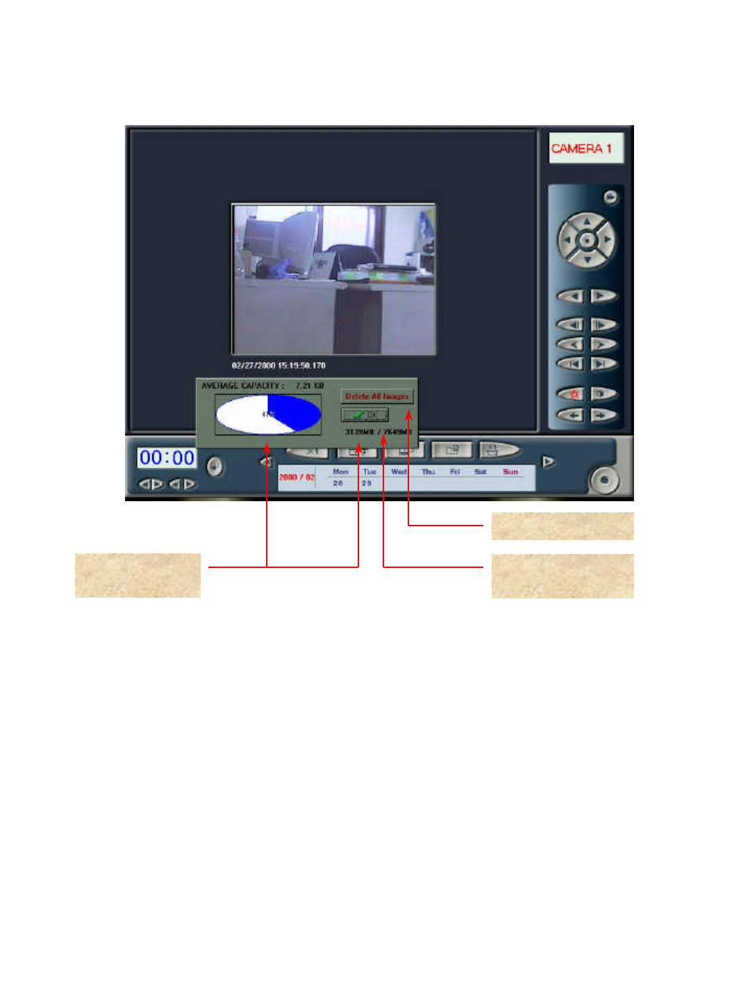
4. Hard Disk Information and Image Delete
Click button to let Disk Information (DISK INFO. ) window become active. Blue-colored gauge
identifies current capacity in use, while white-colored gauge does remaining capacity. Click ‘DELETE ALL
IMAGE’to delete all of saved images of hard disk completely. On the other hand, click ‘OK’to let DISK
INFO. window disappear.
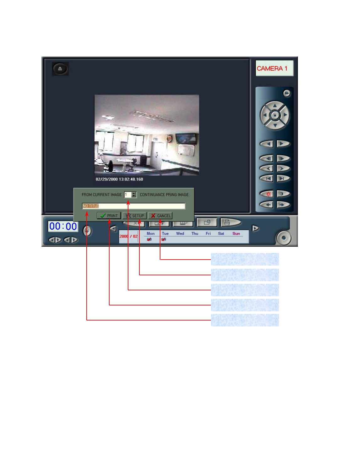
5. Printer Printout
Click button to let Printer Printout window become active. Select number of frame to printout, and
click ‘PRINT’to run printout function after filling out name of images at title box. On the other hand, click
‘CANCEL’to let Printer Printout window disappear.
You may make correction of detailed information on printer in use by using ‘SETUP’button. (For more
information, refer to manual of printer manufacturer.)
1. Enlargement of Search Image
Click button to enlarge images in search 2 to 3 times at Search Program.
35
Chapter 3
JD-Lite LAN/MODEM System Operation
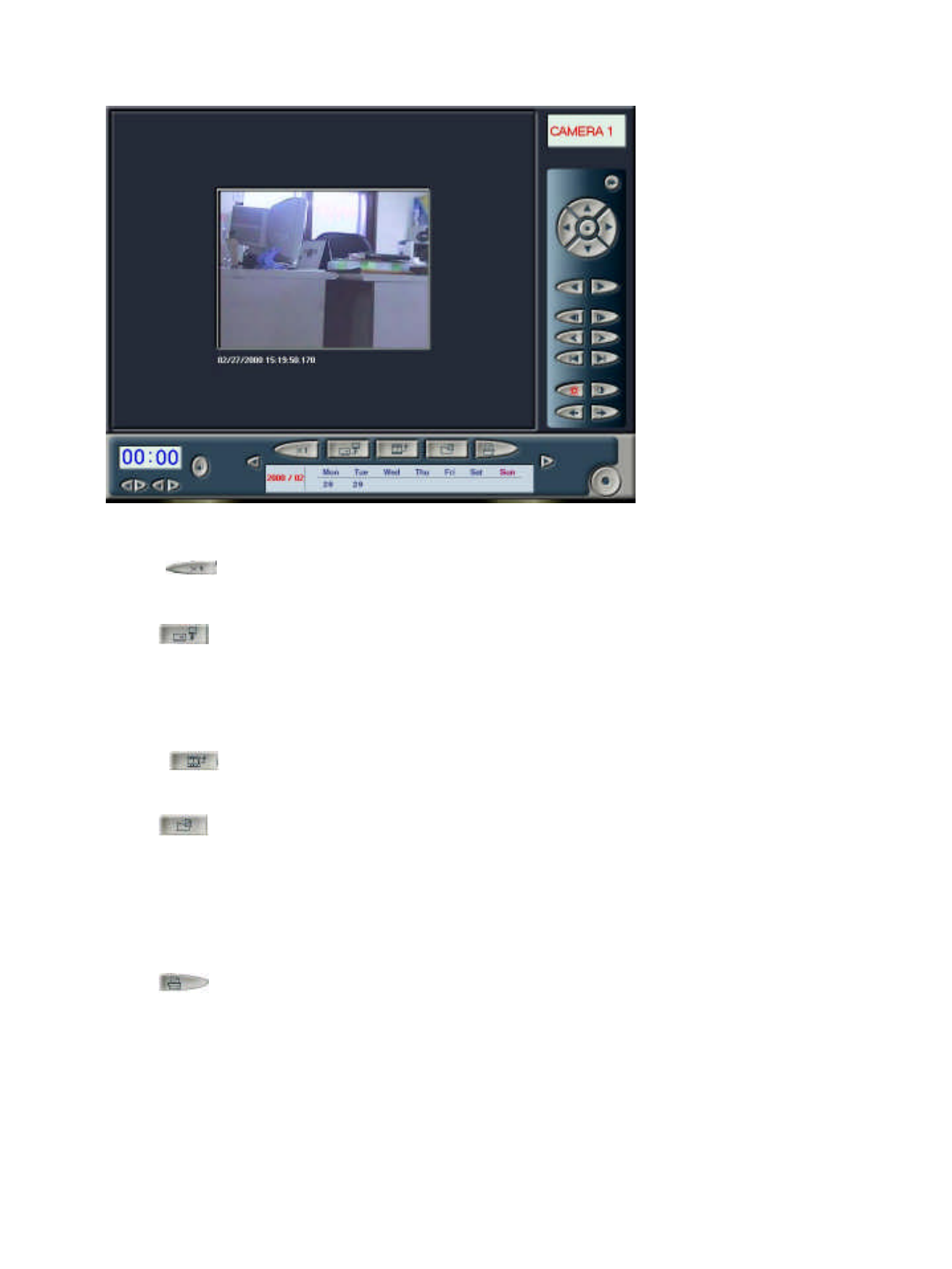
3-1 Client Images Inquiry
1. Image display
2. Saved image
date display
3. Image search
and camera
selection
4. Server connection
environment set up
1. Image display : Display images of selected camera.
2. Saved image date display : Display circle mark at saved date when selected camera saves image.
3. Image search and camera selection : Select camera for image search by using main control panel. You may play or
delete images of selected camera.
4. Server connection environment set up : You may input server name, IP and telephone number to connect with
server system.
Client Images Inquiry program allows you to inquire images in the past, which were transmitted under OFF-Line
without being connected with server.
* Some functions can not be operated with modem.
36
3-1-1. Image Display
1. Camera name : Display name of a selected camera..
2. Saved image date : Display save date of image.
3. Saved image : Display saved image.
Camera name
Saved image
date
Saved image
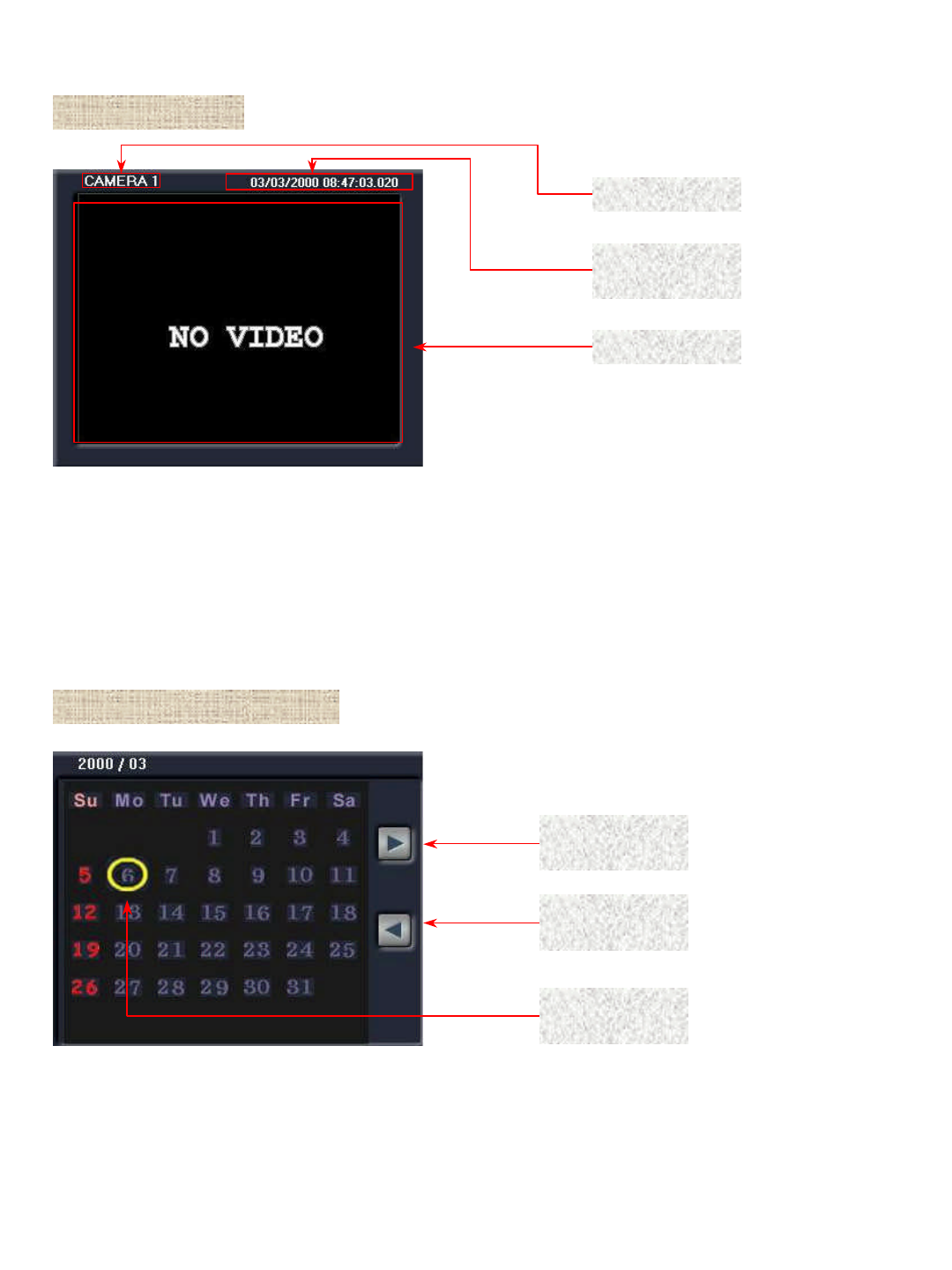
3-1-2. Saved image date display
1. Move to previous month : Move to the month before current search month.
2. Move to next month : Move to the month after current search month.
3. Saved image display : The date saved with an image is to be identified with red-colored circle.
Move to
previous month
Move to next
month
Saved image
display
37
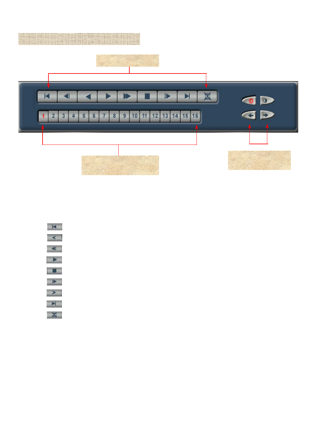
3-1-3. Image Search and Camera Selection
Selection button of No.
1~16 camera
Saved image search
1. Saved Image Search
A. : Move to initial screen of saved image.
B. : Move to 1 minute prior screen before image in search.
C. : Move to previous screen before search
D. : Play saved image.
F. : Suspend an image under play.
G. : Move to a screen following image in search.
H. : Move to a screen 1 minute after image in search.
I. : Move to last screen of saved image.
J. : Delete images in search.
2. Camera selection : Select a camera to search among No. 1~16 camera.
3. Select Bright/Contrast:Choose Bright and Contrast of Images.
Bright/Contrast
Choose
38
3-1-4. Server Connection Environment Set Up
Name of server
Address of server
Server password
set up
Delete of server
Additional
application of
server
Add of server
Server list
box/button Server
connection
Completion
1. Name of server : Select server to connect server list box to display name of server. Click Server Add button and
input name of server to connect additionally.
2. Address of server : Select a server to connect at server list box, and let server IP address make appearance.
Click Server Add button to input IP address and telephone number to connect with new server.
3. Server password set up : Set password of server to connect.
4. Add of server : Register new server additionally.
5. Additional application of server : Apply input contents with Add of Server button.
6. Delete of server : Delete unnecessary lists among the ones connected to server list box.
7. Server list box : Register lists of server. Click the box with mouse, or select lists of server for connection with
button.
8. Server connection : After selecting a server to connect, click the button to connect with server.
9. Completion : Complete the program.
39
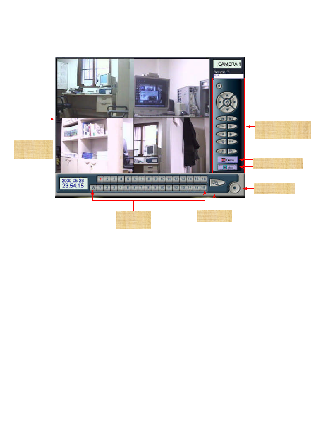
3-2 Server Monitoring
2. Current : Server receives repeated transmission of images.
4. Search : Search an image, which has been saved at server by being switched to Server Image Inquiry
program.
Monitoring
screen
1. Monitoring screen : You can watch monitoring screen as many as number of cameras connected to server in
type of divided screens at clients.
Current/Stop
3. Stop : Suspend transmission of images.
5. PAN/TILT : For more information, refer to ‘2-2-1 Recording Program PAN/TILT Control Panel’of JD-1500
LOCAL System.
PAN/TILT
manipulation
Search
6. Completion : Escape to client control program (without connection with server).
Server Monitoring program allows you to connect with server by using either LAN or WAN at clients to monitor
current images in real time. You can save monitored images in client PC automatically.
Completion
Saving
Image
7. Saving Image : Save Images of seleted Camera number to Client system.
(When A button clicked, save all images of connected cameras.)
40
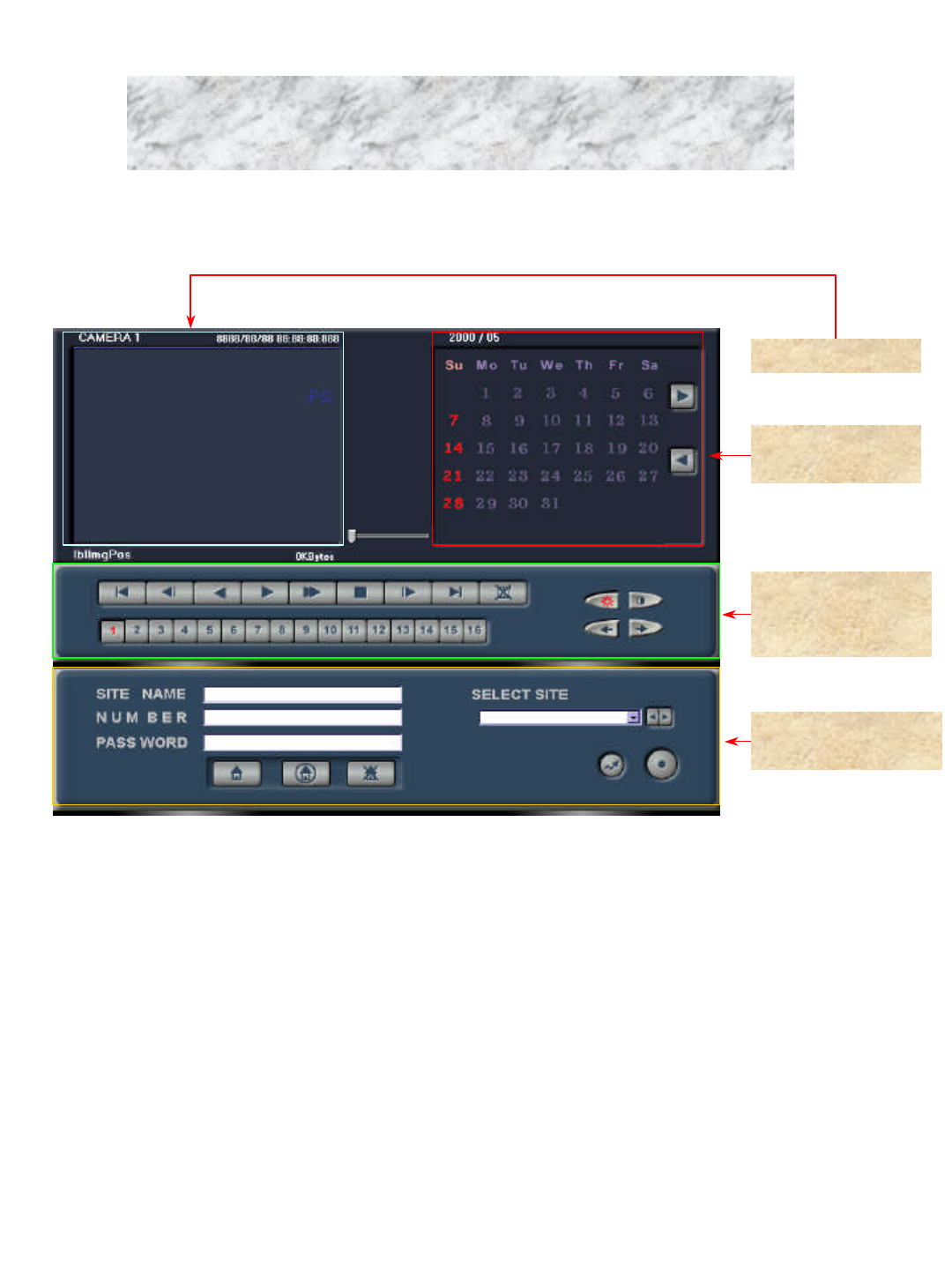
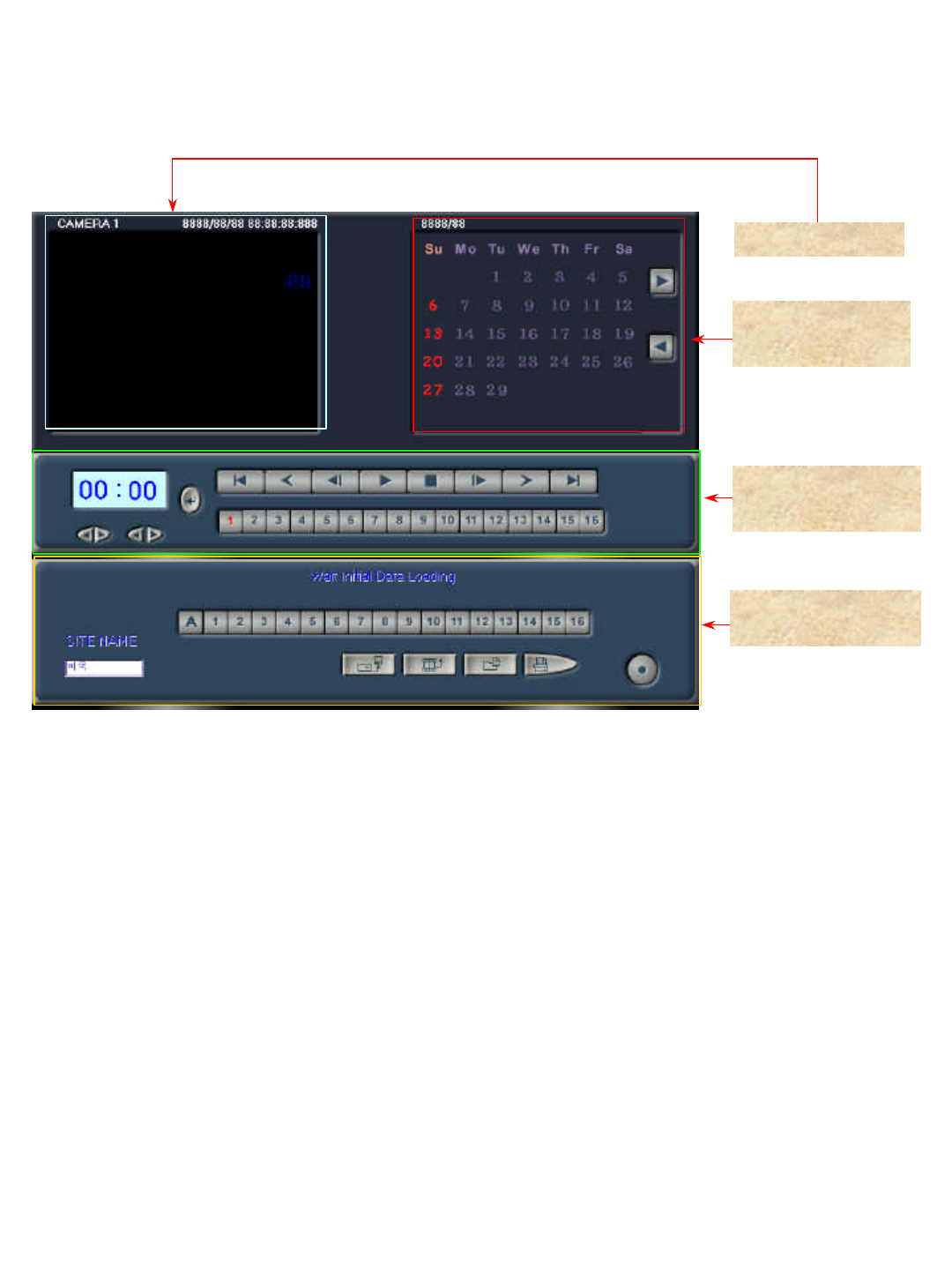
3-3 Server Images Inquiry
1. Image display
2. Saved image
date display
3. Image search and
camera selection
4. Image Save/back-
up/ Output/ Delete
1. Image display : Display images of a selected camera.
2. Saved image date display : Identify date of saved image with circle mark.
3. Image search and camera selection : You may select camera for search by using main control panel of client
program, and can play and delete images of the camera.
4. Image Save/backup/Output/Delete: Save/backup/Output/Delete Past Image from Server.
Server Image Inquiry program allows you to connect with server at client by using LAN, WAN or modem to inquire
or delete images at present and in the past.

41
3-3-1. Image Display
1. Name of camera : Display name of a selected camera.
2. Saved image date : Identify save date of an image.
3. Saved image : Display saved image.
Name of
camera
Saved image
date
Saved image
3-3-2. Image date display
1. Move to previous month : Move to the month before current search month.
2. Move to next month : Move to the month after current search month.
3. Image display : Identify save date of image with red-colored circle.
Move to
previous month
Move to next
month
Image display
42
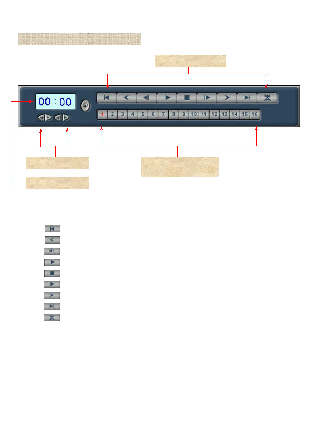
3-3-3. Image Search and Camera Selection
Search time set up
Search time display
Search of saved image
1. Search of saved image
A. : Move to initial screen of save image.
B. : Move to 1 minute before screen of an image under search.
C. : Move to previous screen of an image under search.
D. : Play saved image.
E. : Suspend an image under play.
F. : Move to the screen next to an image under search.
G. : Move to 1 minute after screen of an image under search.
H. : Move to last screen of saved image.
I. : Delete images under search.
2. Search time set up : Input time for search among saved images.
3. Search time display : Identify input time at Search Time Set Up.
Selection button of No.
1~16 camera
4. Camera selection : Select a camera to search among No. 1~16 camera.
( Only 4 cameras can work in JD-Lite S/W )
43
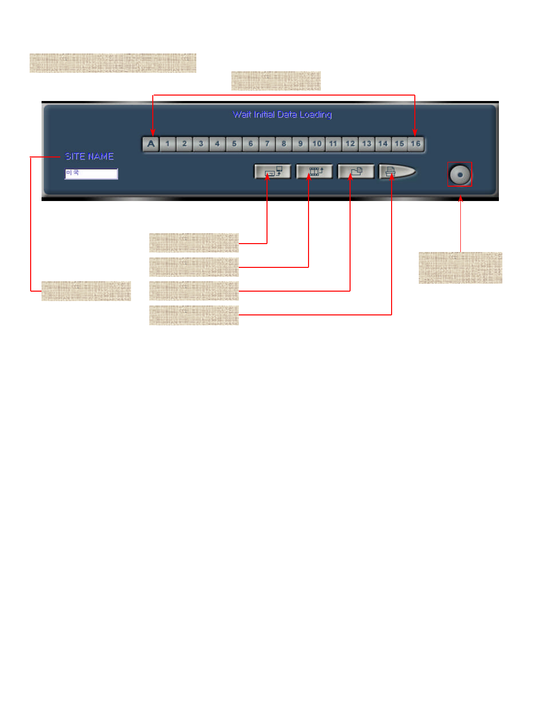
3-3-4. Server Environment Set Up
Completion of
connection
6. Connection completion : Complete connection with server.
FDD BACKUP
UPDATE
DISK INFO
PRINT
SITE NAME
1. Site Name : Name of Connection server.
3. Image update : Update images saved during search.
4. DISK information display : Display current capacity of hard disk.
5. Printout : Printout images with printer.
2. FDD backup : Save currently searching images in a diskette.
7. Saving Image : Save Images of seleted Camera number to Client system.
(When A button clicked, save all images of connected cameras.)
Saving Image

44
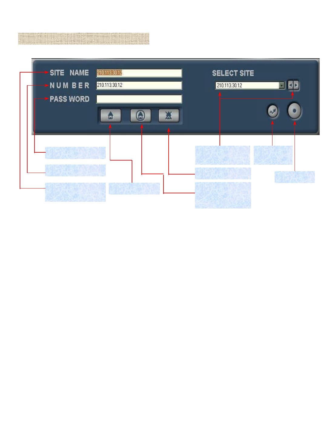
3-4 JD-Lite LAN/MODEM System Operation
1. Run JD-Lite LAN/MODEM program.
2. See ‘3-1. Client Images Inquiry’to know the images that have been saved at client.
3. Select server for connection among lists of ‘Select Site’.
To connect new server additionally, follow operation in order as follows:
A. Click ‘Server Add’to connect to new server.
B. Fill out site name of new server at ‘Site Name’box.
C. Fill out IP address of server to let new server make use of LAN at ‘Number’box. On the other hand, fill out
telephone number for connection to let server to connect to modem.
D. Lastly, click Server Add Application button to register new site at lists of Select Site.
4. Click Server Connection button to connect to server.
5. Connection to server makes Server Monitoring program window become active.
6. Click Search button to check images that have been saved at server.
Click the button to return to Server Images Inquiry screen.
7. Refer to ‘3-4. Client Images Inquiry’to know images that have been saved at server.

45
Chapter 4
Question & Answer of JD-Lite System
Read carefully following cases to help you solve problems properly and save time.
Q. I am unable to save images.
A. If a waveform, system operation mark of recording program, does not move, or a part or all of cameras has not
been saved despite movement of the waveform, check JD-Lite as follows:
1. Check that number of units being connected to JD-Lite has been properly set up
(See ‘Amount’of ‘Control Program -Set Up’).
2. Check that you have selected NTSC of camera mode (See ‘Video’of ‘Control Program-Set Up’.)
3. Check that you have correctly set up amount of camera, and have selected day of the week for recording
(See ‘Reserved’of Control Program-Set Up).
If you do not run sensor, turn all of sensors OFF, and click column of ‘Use Recording Schedule’to run recording of
image.
4. Check that you have clicked ‘Area’, and have selected ‘Selection of Motion Sensibility Mode’as well
as ‘Motion Block’, and have selected ‘Minimum’of ‘Motion Sensibility Control’
(See ‘Motion’of Control Program-Set Up.)
Q. I cannot watch overall screen in the use of PAN/TILT.
A. If you are unable to watch overall screen at center of the screen despite clicking PAN/TILT,
take action as follows:
1. Check that you have clicked option of ‘Run Camera PAN/TILT by overall screen’
(See ‘Video’of Control Program-Set Up.)
Q. Sometimes, I watch broken screen while conducting search.
A. If a part or all of the screen has been broken, take action as follows:
1. Such a phenomenon may occur at different set up of resolution saving between search and saving
(See Video-Control Program -Set Up).
Select ‘DELETE ALL IMAGE’of ‘DISK INFO.’(See Search program), and delete all of saved screens,
and check again.

46
Q. Recording program produces not image, but black-colored screen.
A. If an image is not produced, take action as follows:
1. Check that you have selected ‘32 Bit (True Color) of color attributes of Display Registration
(See Control Panel of Windows).
2. Check whether there is an error of ‘Video Capture64[BSR1000]’of ‘Sound Video and Game Controller’of system
manager tab (See System Registration of control panel of Windows).
3. If same phenomenon may occur under a circumstance in the above, files of system controller is wrong. So, you are
asked to procure a good program.

47
A. In the case, take action as follows:
Q.I have set up Control Program perfectly. But, I cannot run recording.
1. Sensor may cause such a problem. Turn the sensor OFF (See ‘Reservation’of Control Program),
and inspect the sensor again.
A. If so, take action as follows:
Q. Images on display produce ‘noise’similar to lines.
1. Replace camera and lines, which produce noise, with lines of other camera. Then, inspect them again.
2. Video card of the system may cause the problem. Replace your video card, and inspect it again.
3. Monitor may cause the problem. Replace your monitor, and inspect it again.
4. When the problem persists despite your action in the above, contact DVR Business Division of the company.
A. Delete your program completely, and then install it again.
Q. A failure still occurs despite installation of program once again.
1. Delete JD-Lite related program at ‘Add/Delete of Program’of control panel of Windows.
2. Delete ‘_NDE_’directory of D drive.
3. Select ‘Execution (R)’of ‘Start’button to input ‘REGEDIT’and run JD-Lite.
4. Delete ‘BaekSANEnterprise’of ‘SOFTWARE’directory under ‘HKEY-CURRENT-USER’.
5. Install your program again.
6. When the problem still persists despite your action in the above, contact DVR Business Division of the company.
A. Set up all of items of power system control of control panel to be ‘Always turn ON’.
Q. When time elapses under JD-Lite ON, power system is OFF.
1. Click ‘Power system control’icon of control panel of Windows.
2. Select ‘Home use/Office use’of power system configuration.
3. Select ‘Always turn ON’at System Standby, Monitor OFF, and Hard disk OFF.
A. Check that your network runs under normal status.
Q. I cannot connect JD-Lite LAN/MODEM with server.
1. Fill out ‘COMMAND’at ‘Execution (R)’of ‘Start’button. Then, run JF-Lite.
2. When MS-DOS window becomes active, fill out ‘PING 169.254.0.1’under prompt ON.
3. Figures following ‘PING’identifies IP address of server system.
4. When a message of ‘REPLY FROM 169.254.0.1 ….’makes appearance on screen, your server system runs
under normal status.