Junlan Electronic CHT914C HOME THEATER SPEAKER SYSTEM WITH BLUETOOTH User Manual CHT910
Shenzhen Junlan Electronic Ltd HOME THEATER SPEAKER SYSTEM WITH BLUETOOTH CHT910
user manul

Size: 148.5(W) x 210(H)mm (A5)
CONVERTIBLE
SPEAKER SYSTEM
CONVERTIBLE
SPEAKER SYSTEM
Model: CHT914c
PLEASE READ BEFORE OPERATING THIS EQUIPMENT.
Owner's Manual
IMPORTANT SAFETY INSTRUCTIONS
arranged so it will not drape over a laptop, etc. Where it can be pulled on by children or tripped over accidentally.
This unit has a long AC cord and other long cord that can easily be tripped on or pulled on, causing injury. Please make sure
it is arranged so it will not drape over a laptop, etc. Where it can be pulled on by children or tripped over accidentally.
This unit has a long AC cord and other long cord that can easily be tripped on or pulled on, causing injury. Please make sure
it is
12
3
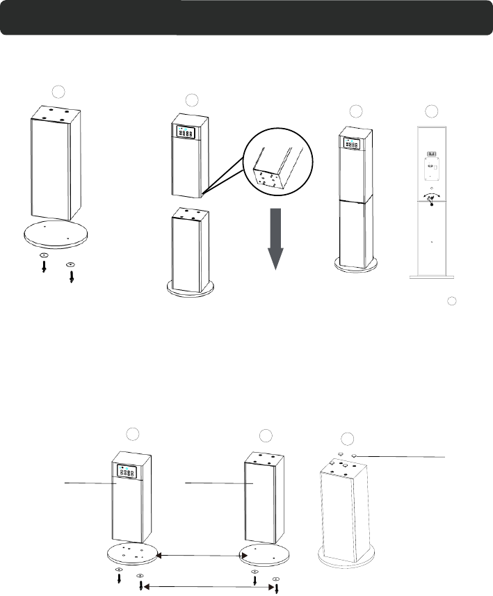
INSTALLATION
3
4
123
Method 1: Assemble the main unit and L Speaker together :
Left Speaker
Supplied
Wooden Stand
Supplied Metallic
Screws and Washers
Method 2: Assemble Main Unit and L Speaker individually :
Main unit Left Speaker
Supplied
Wooden Stand
Supplied Metallic
Screws and Washers
Lock the Hook on the rear of left
speaker to the Main unit as Fig. 4
This unit can be assembled as the following methods: This unit can be assembled as the following methods:
Main Unit
Left Speaker
Decorative Inserts
Note: We supplied total two Wooden Stands and 4 sets Metallic Screws/Washers.Keep the
excess accessories in this assembly method for future use.
4
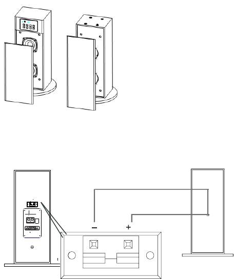
The speaker net can be take out and reassembly as the Figure below:
+
Black wire
Red wire
Main Unit
Left Speaker
AC 120V~ 60Hz
SPEAKER
+
ANT
LR
AUX IN 1
OFF
ON
POWER
After above installation, connect the connection wires (Red and Black) from L Speaker to
the Speaker Connectors on the rear of Main Unit as the figure below:
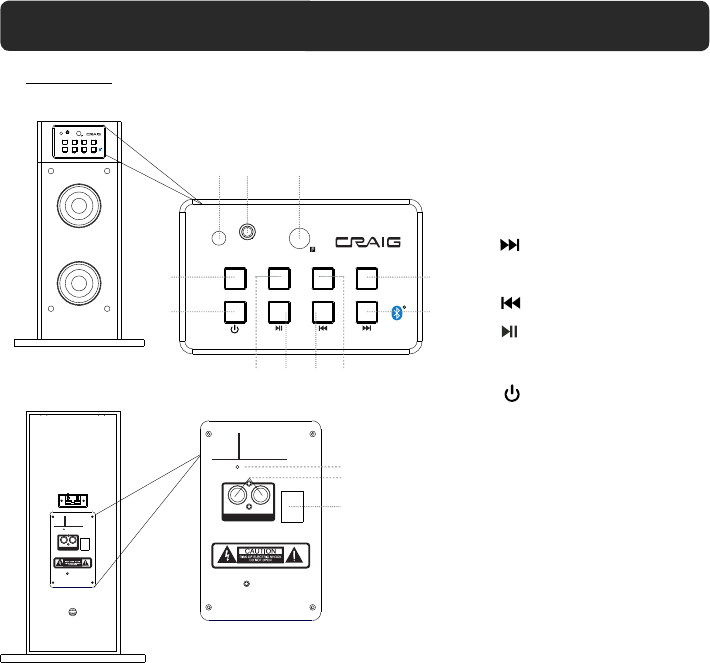
(Play/Pause) button
TUNE - button
SOURCE button
EQ (Equalizer) button
Indicator
Remote Sensor
VOL+ (Volume Up) button
/ TUNE + button
VOL- (Volume Down) button
AUX IN 1 jacks
FM Antenna
AUX IN 2 jack
MAIN UNIT
LOCATION OF CONTROLS
INDICATOR AUX IN 2
EQ SOURCE VOL- VOL+
TUNE- TUNE+
INDICATOR AUX IN 2
EQ SOURCE VOL- VOL+
POWER
TUNE- TUNE+
12
4
5
9876
3
10
11
AC 120V~ 60Hz
SPEAKE R
+
ANT
LR
AUX IN 1
OFF
ON
POWER
ANT
LR
AU X IN 1
OFF
ON
POWER
12
13
14
(Power) button
POWER ON /OFF switch
1.
2.
3.
4.
5.
6.
7.
8.
9.
10.
11.
12.
13.
14.
5
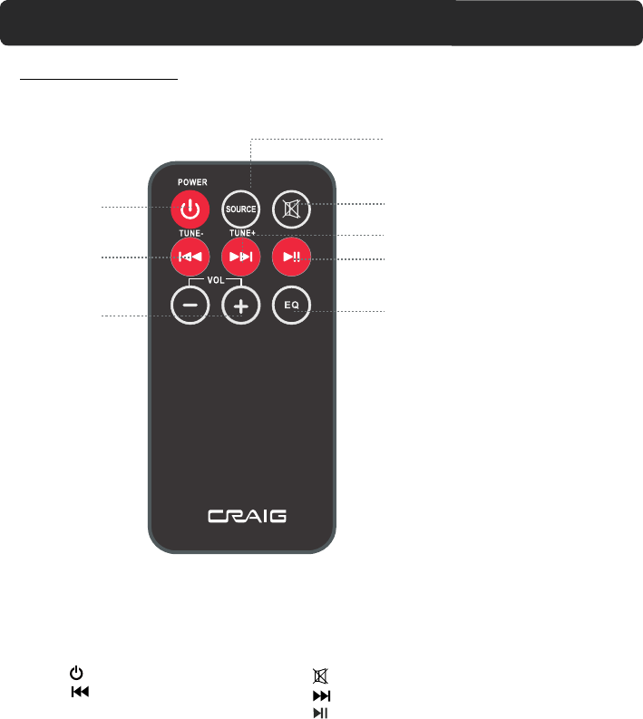
REMOTE CONTROL
1. POWER button
2. /TUNE - button
3. VOL (Volume)+/- buttons
4. SOURCE button
5. (Mute) button
6. / TUNE+ button
7. (Play/Pause) button
8. EQ (Equalizer) button
LOCATION OF CONTROLS
1
2
3
4
5
6
7
8
6
%$77(5<35(&$87,216
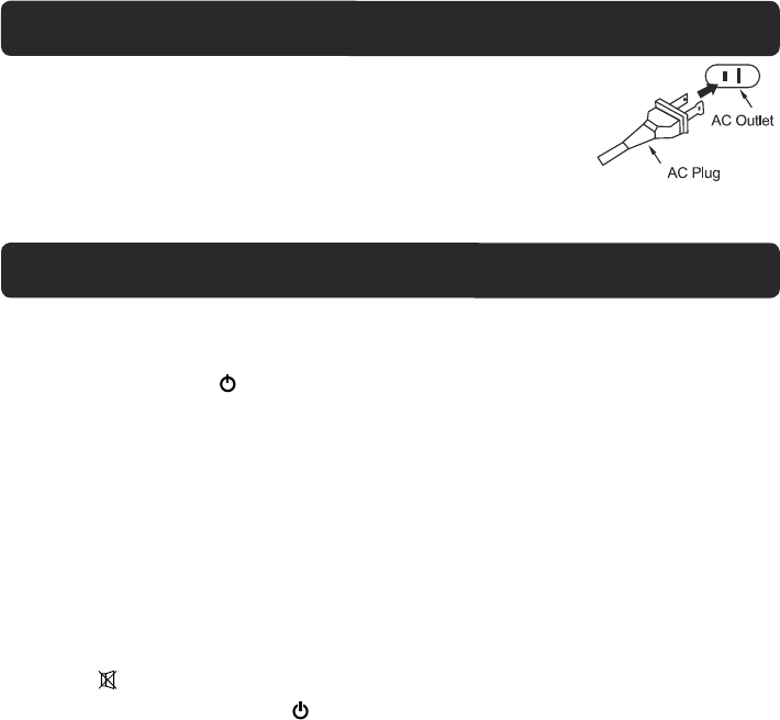
EFFECTIVE DISTANCE OF REMOTE TRANSMITTER
Approx.15 feet
.
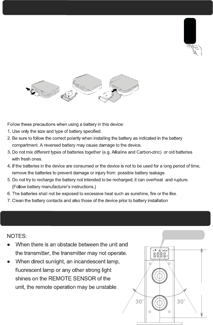
BATTERY INSTALLATION--- REMOTE CONTROL
Remote Sensor (on the
-First Time Use
Remove and discard the insulation tab from the battery tray as figure on the right.
-Replacing Batteries For Remote Control
1. Push and slide out the battery holder as figure 1 below.
2. Replace the battery with a new CR2025 button cell as the polarity
markings on the rear of the Remote Control.
3. Close the battery holder.
Fig.1 Fig.2 Fig.3
front of the main unit)
INDICATOR AUX IN 2
EQ SOURCE VOL- VOL+
POWER
TUNE- TUNE+
7
GENERAL OPERATIONS
1. Insert the plug from AC Power Cord into AC wall outlet having AC 120V~ ; 60Hz.
corresponding color as below:
4. During Playback:
~ Press the VOL (Volume) +/- buttons to adjust volume level as desired.
~ Press the EQ button repeatedly to select and set equalizer mode as to Jazz; Pop; Classic or Rock.
~ Press the (Mute) button on the Remote Control to turn off the sound. Press again to resume.
5. When finished listening, press the Power button to .
NOTE:
3. Press the SOURCE button repeatedly to switch to desired mode.The indicator will turn to the
as desire. ( .)
To reset the EQ to normal mode, power Off then power On the unit
turn the unit to Power Off (Standby) mode.
If long period of time will not use the unit, shut off the unit by press the POWER ON/OFF switch on
the rear of main unit to OFF position
from Standby mode.
Insert the AC plug into a conveniently located AC outlet having AC 120V~ ; 60Hz.
NOTE: The AC plug supplied with the unit is polarized to help minimize the
obsolete outlet.
possibility of electric shock. If the AC plug dose not fit into a non polarized
AC outlet, do not file or cut the wide blade. It is the user's responsibility to
have an electrician replacing the
POWER SOURCE
~ Purple: AUX IN 1
~ Orange: AUX IN 2
~ Blue: Bluetooth
~ Green: Radio
2. Press the Power ON/OFF switch on the rear of the Main Unit to ON position.The Red Indicator
will light. Then press the Power button on the Main Unit or Remote Control to power on the
unit
or unplug the AC Cord from wall outlet.
8
FM Antenna
LISTEN TO FM RADIO
1. Power ON the unit as previous procedures.
2. Press the SOURCE button repeatedly until the color of Indicator changes to Green.
4. Repeat the same procedures until the desired radio station is received.
NOTE: If the received FM station is in stereo mode, the unit will play it in stereo mode automatically.
3. Press and hold the /TUNE - or /TUNE + buttons until the indicator starts blinking.
The unit will start to search next (or previous) available FM radio station then plays.
The Antenna wire on the rear of Main Unit is for radio reception. If reception is weak, unwind and
extend the wire or relocate the wire to improve the radio reception.
White
Red
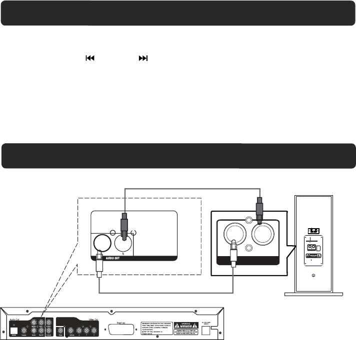
LISTEN TO TV/DVD/VCR/DVR
X IN 1
Audio out jacks on
TV/DVD/ VCR/DVR
DVD
AUX IN 1
N 1
4. Press the SOURCE button repeatedly until the color of Indicator changes to Purple.
1. Connect one end of supplied RCA audio connection cable to the AUX IN 1 jacks on the rear
of the unit as the figure above.
2. Connect the other end to the Audio out jacks on the external player (such as Television, VCR, DVD
Player, DVR ... etc.).
5. Plays the music in the external player as usual. (Make sure the volume output level of the player is
in high level. Otherwise, sound from this unit is weak).
3. Power ON the unit as previous procedures.
LR
A UX IN 1
AC 120V~ 60Hz
SPEAKER
+
ANT
LR
AUX IN 1
OFF
ON
POWER
9
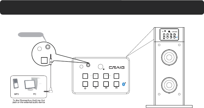
3. Power ON the unit as previous procedures.
4. Press the SOURCE button repeatedly until the color of Indicator changes to Orange.
1. Connect one end of supplied audio connection cable to the AUX IN 2 jack on the top of the unit
2. Connect the other end to the Audio out/Line out/Phone jack on the external player (such like iPod,
iPhone, iPad, MP3 Player, Discman... etc.).
5. Plays the music in the external player as usual. (Make sure the volume output level of the player
is in high level. Otherwise, sound from this unit is weak).
as the figure above.
LISTEN TO EXTERNAL AUDIO DEVICES
INDICATOR AUX IN 2
EQ SOURCE VOL- VOL+
TUNE- TUNE+
INDICATOR AUX IN 2
AUX IN 2 jack INDICATOR A UX IN 2
EQ SOURCE V OL- VOL+
TUNE- TUN E+
10

BLUETOOTH PARING AND PLAYBACK
NOTES:
In first time use, pairing the external BT device as below:
A. Power ON the unit as previous procedures, press the SOURCE button repeatedly until the
indicator turns to Blue and blinking.
B. Power ON the external BT player and enter to searching mode. Start pairing as the on screen
instructions on the external BT Player (For details pairing procedures, please refer to the user’s
manual of your BT device.).
C. When the external BT player searched the Speaker, our model number “CHT914C” will appear on
the display of external BT device. Pairing code “0000” may need to enter.
1. Power ON the unit as previous procedures.
2. Press the SOURCE button on the unit or remote control until the indicator changes to Blue.
3. Turn on the BT function on the external BT device and play the music as usual. (Make sure
the volume level of the external BT device is set to high level).
4. During palyback:
Press the VOL (Volume) +/- buttons to adjust volume level.
Press the / TUNE- or / TUNE + button to skip track.
Press the (Play/Pause) button to pause. Press again to resume normal playback.
11

&KHFNWKHIROORZLQJVEHIRUHUHTXHVWLQJVHUYLFH
6<03720 3266,%/(&$86( 3266,%/(628/7,21
TROUBLESHOOTING GUIDE
Reduce the bass level of the connected
device
Press the SOURCE button repeatedly to
set the input source to the desired mode
No power
No sound
Sound distortion
Remote not
working
Bluetooth
reception failure
Have not paired
consumed
The battery is
The external device is far from
the unit
Volume level too high
Bass level of the connected
device too high
Input source incorrect
The connected device is not
in payback mode
Volume in minimum position
AC plug not connected to the
wall outlet Plug to the wall outlet.
Raise volume level by pressing the VOL
(Volume) + button
Play the music/movie in the connected
device as usual and make sure the
volume level of it is in high level
VOL (Volume ) - button
Reduce the volume level by pressing
the
Replace with new battery
Put the external BT device close to the
unit
Pair both unit as BT pairing page
12

z
$FFHVVRULHV
GENERAL SPECIFICATIONS
Power Source.......................................................................................................... AC 120V ~60Hz
Power Consumption...................................................................................................................45W
1 x User Manual
1 x Stereo Audio Connection Cable with 3.5mm stereo plug
4 x Assembly Screws / Washers
2 x Wooden Bases
1 x RCA cable
Radio Coverage ...............................................................................................FM 87.5 -108.0 MH
Impedance of Speakers:
Loud Speakers........................................................................................................ 8 Ohm, 10W x 2
Tweeters................................................................................................................... 8 Ohm, 5W x 2
Bluetooth Effective Range.............................................................................................Up to 30 feet
Remote Effective Range...............................................................................................Up to 15 feet
1 x Remote Control
1 x CR 2025 Button Cell (For Remote Control, already installed)
(Measured in open area. Wall and structures may affect the effective range.)
13

Size: 148.5(W) x 210(H)mm (A5)
Craig warrants this product to be free from manufacturing defects in material and
workmanship under normal use for a period of 90 days from date of purchase. If service
is required, please return the product to the store where it was purchased for exchange;
or, pack the unit in the original packing material with all accessories if applicable, a copy
of your sales receipt and a Cashier’s check or Money Order for $15.00 (to cover shipping
and handling costs) payable to Craig Electronics Inc. For consumers in Canada, please
make sure that the cashier check or money order is redeemable through a U.S. bank.
Ship your product freight pre-paid. Your unit will be repaired, replaced or if the unit can
not be repaired or replaced, a refund will be forwarded to you within four weeks of receipt
of your unit. Please ship your unit to:
Craig Electronics Inc.
1160 NW 163 Drive
Miami, Fl 33169
This warranty is void if the product has been: a) Used in a commercial application or
rental. b) Damaged through misuse, negligence, or abuse. c) Modified or repaired by
anyone other than an authorized Craig service center. d) Damaged because it is
improperly connected to any other equipment.
Note: This warranty does not cover: a) Ordinary adjustments as outlined in the Owner’s
Manual which can be performed by the customer. b) Damage to equipment not properly
connected to the product. c) Any cost incurred in shipping the product for repair. d)
Damage to the product not used in the USA.
This warranty is not transferable and only applies to the original purchase. Any implied
warranties, including the warranty of merchantability, are limited in duration to the period
of this expressed warranty and no warranty whether expressed or implied shall apply to
the product thereafter.
Under no circumstance shall Craig be liable for any loss or consequential damage arising
out of the use of this product. This warranty gives specific legal rights. However, you may
have other rights which may vary from state to state. Some states do not allow limitations
on implied warranties or exclusion of consequential damage. Therefore, these
restrictions may not apply to you.
To Obtain Service on your Product
email:service@craigelectronics.com
Printed in China CHT914c_WC_E0CL1_V0US
LIMITED WARRANTY
FCC STATEMENT
1. This device complies with Part 15 of the FCC Rules. Operation is subject to the
following two conditions:
(1) This device may not cause harmful interference.
(2) This device must accept any interference received, including interference that may
cause undesired operation.
Changes or modifications not expressly approved by the party responsible for compliance
could void the user's authority to operate the equipment.
NOTE: This equipment has been tested and found to comply with the limits for a Class B
digital device, pursuant to Part 15 of the FCC Rules. These limits are designed to provide
reasonable protection against harmful interference in a residential installation.
This equipment generates uses and can radiate radio frequency energy and, if not
installed and used in accordance with the instructions, may cause harmful interference to
radio communications. However, there is no guarantee that interference will not occur in a
particular installation. If this equipment does cause harmful interference to radio or
television reception, which can be determined by turning the equipment off and on, the
user is encouraged to try to correct the interference by one or more of the following
measures:
Reorient or relocate the receiving antenna.
Increase the separation between the equipment and receiver.
Connect the equipment into an outlet on a circuit different from that to which the
receiver is connected.
Consult the dealer or an e xperienced radio/TV technician for help.