K Best Technology 5113R E1 Spread Spectrum Radios User Manual 1
K-Best Technology Inc. E1 Spread Spectrum Radios 1
Contents
- 1. User Manual 1
- 2. User Manual 2
- 3. User Manual 3
User Manual 1

1
I
Regulatory Notice※※
z To comply with the relevant FCC regulations, changes or modifications are
not expressly allowed as it will arbitrarily uses or alters the radio frequency
signals in violation, which may void the user’s authority to operate this
equipment.
z Low power radio frequency device must be professionally installed.
z For safety reasons, the working condition must not alters the RF signal.
When installing this equipment, observe the following precautions to
minimize the danger of personnel injury:
1. Antenna used for this device must be fix-mounted on permanent outdoor
structures to provide 5 meters or more separation from all persons during
device operation to comply with FCC RF exposure requirements.
2. Always disconnect all power connections before installing antenna.

I
Warning※※
z If low power RF devices interference endangers the functioning of a radio
navigation service or of other safety maintenance services or seriously
degrades, obstructs, or repeatedly interrupts a legitimate radio
communication service, it is required to terminate the operation and take
steps to improve so as to eliminate future interference.
z Low power RF devices MUST tolerate all legitimate ISM band
interferences.
z The above legal telecommunications are based on the
Telecommunications Act of Radio Telecommunication Equipment.
II
Table of Contents
1 Introduction ........................................................................................................................1-1
2 Features.............................................................................................................................2-1
2.1 E1 Spread Spectrum Radios............................................................................................................... 2-1
2.2 Core Technology ................................................................................................................................. 2-1
2.3 Composition and Principle .................................................................................................................. 2-2
2.3.1 System Composition............................................................................................................................................ 2-2
2.3.2 System Principle................................................................................................................................................. 2-2
3 Technological Characteristics ............................................................................................3-1
4 Product Description............................................................................................................4-1
4.1 Indoor(IDU)/Modem ............................................................................................................................ 4-1
4.1.1 General Description........................................................................................................................................... 4-1
4.2 Outdoor(ODU)/RF Unit........................................................................................................................ 4-4
4.2.1 General Description........................................................................................................................................... 4-4
4.3 Date Port Guide .................................................................................................................................. 4-5
5 Interface.............................................................................................................................5-1
5.1 Front Panel.......................................................................................................................................... 5-1
5.1.1 Engineering Order Wire(EOW).......................................................................................................................... 5-1
5.1.2 LCD Description ................................................................................................................................................ 5-2
5.2 LCD Operation .................................................................................................................................... 5-5
5.2.1 IDU Info ............................................................................................................................................................. 5-5
5.2.2 ODU Info.......................................................................................................................................................... 5-10
5.2.3 Test Item............................................................................................................................................................ 5-13
5.2.4 Remote Info....................................................................................................................................................... 5-20
5.2.5 Config Info........................................................................................................................................................ 5-22
6 Environmental Condition....................................................................................................6-1
6.1 Cable................................................................................................................................................... 6-1
6.2 Operating Temperature Range ........................................................................................................... 6-1
6.3 DC Input Voltage ................................................................................................................................. 6-1
6.4 Power Consumption............................................................................................................................ 6-1
6.5 Humidity .............................................................................................................................................. 6-1
7 Software Installation...........................................................................................................7-1
8 Arbeit NMS Software .........................................................................................................8-4
8.1 Open Arbeit NMS ................................................................................................................................ 8-4
8.2 Login ................................................................................................................................................... 8-4
8.3 Initialize ............................................................................................................................................... 8-5
III
8.3.1 IDU Setting......................................................................................................................................................... 8-6
8.3.2 Link Setting......................................................................................................................................................... 8-7
8.3.3 ODU Setting....................................................................................................................................................... 8-8
8.3.4 Alarm Setting...................................................................................................................................................... 8-9
8.3.5 Cross Connecting ............................................................................................................................................. 8-10
8.3.6 User I/O Setting................................................................................................................................................ 8-12
8.4 Superuser.......................................................................................................................................... 8-13
8.5 System Setting .................................................................................................................................. 8-18
8.5.1 Background Setting .......................................................................................................................................... 8-18
8.5.2 COM port Setting ............................................................................................................................................. 8-20
8.5.3 Record Saving Time.......................................................................................................................................... 8-21
8.6 User Setting ...................................................................................................................................... 8-21
8.7 System Test ...................................................................................................................................... 8-24
8.7.1 Local Loopback................................................................................................................................................ 8-25
8.7.2 IF Loopback ..................................................................................................................................................... 8-26
8.7.3 RF Loopback .................................................................................................................................................... 8-27
8.7.4 Remote Loopback ............................................................................................................................................. 8-28
8.7.5 PRBS Test ......................................................................................................................................................... 8-29
8.8 System Record.................................................................................................................................. 8-30
8.8.1 Alarm Record.................................................................................................................................................... 8-30
8.8.2 Event Record .................................................................................................................................................... 8-33
8.8.3 Login Record .................................................................................................................................................... 8-34
8.8.4 Report Export ................................................................................................................................................... 8-35
8.9 Help................................................................................................................................................... 8-37
8.9.1 Help.................................................................................................................................................................. 8-37
8.9.2 About Arbeit...................................................................................................................................................... 8-37
8.10 Monitor .............................................................................................................................................. 8-38
8.10.1 Network Monitor.......................................................................................................................................... 8-38
8.10.2 Real-time Alarm........................................................................................................................................... 8-45
8.10.3 Dial-up......................................................................................................................................................... 8-46
9 Appendices ........................................................................................................................9-1
9.1 Specifications ...................................................................................................................................... 9-1
9.2 LCD Alarm Items ................................................................................................................................. 9-5
9.3 LCD Function ...................................................................................................................................... 9-6
9.4 Spread Spectrum List.......................................................................................................................... 9-8
9.5 ODU IF & RF Status.......................................................................................................................... 9-12
9.5.1 2.4GHz Status................................................................................................................................................... 9-12
IV
9.5.2 5.8GHz Status................................................................................................................................................... 9-13
9.6 The Definition of Pins ........................................................................................................................ 9-14
9.7 Installation Guide .............................................................................................................................. 9-17
9.7.1 Parts of ODU assembly.................................................................................................................................... 9-17
9.7.2 ODU Installation Diagram............................................................................................................................... 9-18
9.7.3 IDU+ODU Quick Installation.......................................................................................................................... 9-19
9.7.4 Antenna Installation ......................................................................................................................................... 9-20
9.8 RSL and Link Budget ........................................................................................................................ 9-21
V
Figures
Figure 2-1 E1 IDU Block Diagram.............................................................................................................. 2-2
Figure 4-1 Front Panel (2E1,RJ-48)........................................................................................................... 4-1
Figure 4-2 Front Panel (8E1,RJ-48)........................................................................................................... 4-1
Figure 4-3 Accessories............................................................................................................................... 4-1
Figure 4-4 LCD Display .............................................................................................................................. 4-2
Figure 4-5 LCD Function Key..................................................................................................................... 4-3
Figure 4-6 User I/O Port DB-26 pin............................................................................................................ 4-3
Figure 4-7 ODU Display ............................................................................................................................. 4-4
Figure 4-8 Data Port Settings (1) ............................................................................................................... 4-5
Figure 4-9 Data Port Settings (2) ............................................................................................................... 4-6
Figure 4-10 Data Port Settings (3) ............................................................................................................. 4-6
Figure 4-11 Data Port Settings (4).............................................................................................................. 4-7
Figure 5-1 IDU Function Tree..................................................................................................................... 5-2
Figure 5-2 LCD Function Keys (1) ............................................................................................................. 5-2
Figure 5-3 LCD Function Keys (2) ............................................................................................................. 5-3
Figure 5-4 Alarm Status.............................................................................................................................. 5-3
Figure 5-5 Alarm Function .......................................................................................................................... 5-4
Figure 5-6 Buzzer OFF............................................................................................................................... 5-4
Figure 5-7 IDU Info..................................................................................................................................... 5-5
Figure 5-8 Local ID..................................................................................................................................... 5-5
Figure 5-9 EOW No:n................................................................................................................................. 5-5
Figure 5-10 IDU Type: nXE1 ...................................................................................................................... 5-6
Figure 5-11 Code:HDB3/AMI...................................................................................................................... 5-7
Figure 5-12 Code Switch (1) ...................................................................................................................... 5-7
Figure 5-13 Code Switch (2) ...................................................................................................................... 5-7
Figure 5-14 Code Switch (3) ...................................................................................................................... 5-8
Figure 5-15 Code Switch (4) ...................................................................................................................... 5-8
Figure 5-16 AUX1:RS232/RS422............................................................................................................... 5-8
Figure 5-17 AUX2:ASY-CH/SYN-CH.......................................................................................................... 5-9
Figure 5-18 I-Temp:n℃.............................................................................................................................. 5-9
Figure 5-19 Buzzer:On/Off ....................................................................................................................... 5-10
Figure 5-20 Restart EMU:Y/N .................................................................................................................. 5-10
Figure 5-21 ODU Info ............................................................................................................................... 5-10
Figure 5-22 RF-CH:n.................................................................................................................................5-11
Figure 5-23 TxL-SET:ndBm.......................................................................................................................5-11
VI
Figure 5-24 SSPA:On/Off ..........................................................................................................................5-11
Figure 5-25 O-Temp:n℃........................................................................................................................... 5-12
Figure 5-26 ATPC:Off ............................................................................................................................... 5-12
Figure 5-27 RSLtrig: n dBm ..................................................................................................................... 5-12
Figure 5-28 Test Item ............................................................................................................................... 5-13
Figure 5-29 Enter Password .................................................................................................................... 5-13
Figure 5-30 Tn-L-LP:En/Dis (1)................................................................................................................ 5-14
Figure 5-31 Tn-L-LP:En/Dis (2)................................................................................................................ 5-14
Figure 5-32 Tn-L-LP:En/Dis (3)................................................................................................................ 5-14
Figure 5-33 Tn-L-LP:En/Dis (4)................................................................................................................ 5-15
Figure 5-34 Tn-R-LP:En/Dis (1) ............................................................................................................... 5-15
Figure 5-35 Tn-R-LP:En/Dis (2) ............................................................................................................... 5-16
Figure 5-36 Tn-PRBS:En/Dis ................................................................................................................... 5-16
Figure 5-37 Ber-Clear............................................................................................................................... 5-17
Figure 5-38 Count-Add:n.......................................................................................................................... 5-18
Figure 5-39 P-Acc-T:nS............................................................................................................................ 5-18
Figure 5-40 IF-Loop:En/Dis (1) ................................................................................................................ 5-18
Figure 5-41 IF-Loop:En/Dis (2) ................................................................................................................ 5-19
Figure 5-42 RF-Loop:En/Dis .................................................................................................................... 5-19
Figure 5-43 Close-Test............................................................................................................................. 5-19
Figure 5-44 Remote Info .......................................................................................................................... 5-20
Figure 5-45 Remote ID:n.......................................................................................................................... 5-20
Figure 5-46 Far-End:OK/Alarm/Loss/Test ................................................................................................ 5-21
Figure 5-47 R-Status:Test/Normal............................................................................................................ 5-21
Figure 5-48 R-AUX2:ASY-CH/SYN-CH.................................................................................................... 5-21
Figure 5-49 Config Info............................................................................................................................. 5-22
Figure 5-50 MODEM:ON/OFF ................................................................................................................. 5-22
Figure 5-51 SYS-Conf:1+1/1+0................................................................................................................ 5-22
Figure 5-52 Tx:Active/Standby ................................................................................................................. 5-23
Figure 5-53 Rx:Active/Standby................................................................................................................. 5-23
Figure 5-54 Power:-36 ~ -72V.................................................................................................................. 5-23
Figure 5-55 Date:Year/Month/Day............................................................................................................ 5-24
Figure 5-56 Time: Hour/Min/Sec .............................................................................................................. 5-24
Figure 7-1 Software Installation (1) ............................................................................................................ 7-1
Figure 7-2 Software Installation (2) ............................................................................................................ 7-1
Figure 7-3 Software Installation (3) ............................................................................................................ 7-2
Figure 7-4 Software Installation (4) ............................................................................................................ 7-2
VII
Figure 7-5 Software Installation (5) ............................................................................................................ 7-3
Figure 7-6 Software Installation (6) ............................................................................................................ 7-3
Figure 8-1 Open Arbeit ............................................................................................................................... 8-4
Figure 8-2 Login Arbeit ............................................................................................................................... 8-4
Figure 8-3: Arbeit’s User name and Password........................................................................................... 8-5
Figure 8-4: Initialize .................................................................................................................................... 8-6
Figure 8-5: IDU Setting............................................................................................................................... 8-6
Figure 8-6 Link Setting ............................................................................................................................... 8-7
Figure 8-7 Link ........................................................................................................................................... 8-7
Figure 8-8: ODU Setting............................................................................................................................. 8-8
Figure 8-9: Alarm Setting............................................................................................................................ 8-9
Figure 8-10: Cross Connecting (1)........................................................................................................... 8-10
Figure 8-11: Cross Connecting (2) ............................................................................................................8-11
Figure 8-12: User I/O Setting ................................................................................................................... 8-12
Figure 8-13: Superuser ............................................................................................................................ 8-13
Figure 8-14: Station Setup (1) .................................................................................................................. 8-13
Figure 8-15: Station Setup (2) .................................................................................................................. 8-14
Figure 8-16: Station Setup (3) .................................................................................................................. 8-15
Figure 8-17: Station Setup (4) .................................................................................................................. 8-15
Figure 8-18: Temperature Alarm Threshold ............................................................................................. 8-16
Figure 8-19: Terminal/Center Station ....................................................................................................... 8-17
Figure 8-20: System Setting..................................................................................................................... 8-18
Figure 8-21: Background Setting (1) ........................................................................................................ 8-18
Figure 8-22: Background Setting (2) ........................................................................................................ 8-19
Figure 8-23: Background Setting (3) ........................................................................................................ 8-19
Figure 8-24: Background Setting Complete............................................................................................. 8-20
Figure 8-25: COM port Setting ................................................................................................................. 8-20
Figure 8-26: Record Saving Time ............................................................................................................ 8-21
Figure 8-27: User Setting ......................................................................................................................... 8-22
Figure 8-28: User List............................................................................................................................... 8-22
Figure 8-29: Change Superuser Login Setting (1) ................................................................................... 8-23
Figure 8-30: Change Superuser Login Setting (2) ................................................................................... 8-23
Figure 8-31: System Test (1) .................................................................................................................... 8-24
Figure 8-32: System Test (2) .................................................................................................................... 8-25
Figure 8-33: Local Loopback.................................................................................................................... 8-25
Figure 8-34: Local Loopback Setting ....................................................................................................... 8-26
Figure 8-35: IF Loopback ......................................................................................................................... 8-26
VIII
Figure 8-36: IF Loopback Setting............................................................................................................. 8-27
Figure 8-37: RF Loopback........................................................................................................................ 8-27
Figure 8-38: RF Loopback Setting ........................................................................................................... 8-28
Figure 8-39: Remote Loopback................................................................................................................ 8-28
Figure 8-40: Remote Loopback Setting ................................................................................................... 8-29
Figure 8-41: PRBS Test............................................................................................................................ 8-29
Figure 8-42: PRBS Test Setting ............................................................................................................... 8-30
Figure 8-43: Alarm Record (1).................................................................................................................. 8-31
Figure 8-44: Alarm Record (2).................................................................................................................. 8-31
Figure 8-45: Sort by Date......................................................................................................................... 8-32
Figure 8-46: Sort by Station...................................................................................................................... 8-32
Figure 8-47: Select All Alarm Records ..................................................................................................... 8-33
Figure 8-48 Event Record (1)................................................................................................................... 8-33
Figure 8-49 Event Record (2)................................................................................................................... 8-34
Figure 8-50: Login Record........................................................................................................................ 8-34
Figure 8-51: Deleting Login Record ......................................................................................................... 8-35
Figure 8-52: Report Export (1) ................................................................................................................. 8-35
Figure 8-53: Report Export (2) ................................................................................................................. 8-36
Figure 8-54: Help...................................................................................................................................... 8-37
Figure 8-55: Function Explanations ......................................................................................................... 8-37
Figure 8-56 About Arbeit........................................................................................................................... 8-38
Figure 8-57: Network Monitor (1) ............................................................................................................. 8-38
Figure 8-58: Network Monitor (2) ............................................................................................................. 8-39
Figure 8-59: Network Monitor Links ......................................................................................................... 8-40
Figure 8-60: Equipment Status................................................................................................................. 8-41
Figure 8-61: ODU Status .......................................................................................................................... 8-42
Figure 8-62: Link Status ........................................................................................................................... 8-42
Figure 8-63 User I/O Status...................................................................................................................... 8-43
Figure 8-64 Cross Connect Status ........................................................................................................... 8-43
Figure 8-65 Interval Status ....................................................................................................................... 8-44
Figure 8-66 Interval Info ........................................................................................................................... 8-44
Figure 8-67 Other Information.................................................................................................................. 8-45
Figure 8-68: Real-time Alarm (1).............................................................................................................. 8-46
Figure 8-69: Real-time Alarm (2).............................................................................................................. 8-46
Figure 8-70: No Real-time Alarm.............................................................................................................. 8-46
Figure 8-71 DialUp (1).............................................................................................................................. 8-47
Figure 8-72 DialUp (2).............................................................................................................................. 8-47
IX
Figure 8-73 DialUp (3).............................................................................................................................. 8-48
Figure 9-1 Side A IF & RF Status ............................................................................................................. 9-12
Figure 9-2 Side B IF & RF Status............................................................................................................. 9-12
Figure 9-3 Side A IF & RF Status ............................................................................................................. 9-13
Figure 9-4 Side B IF & RF Status............................................................................................................. 9-13
Figure 9-5 Part accessories ..................................................................................................................... 9-17
Figure 9-6 ODU Installation Diagram ....................................................................................................... 9-18
Figure 9-7 IDU & ODU Connection Diagram ........................................................................................... 9-19
Figure 9-8 RSL and Link Budget .............................................................................................................. 9-21
X
Tables
Table 9-1 Transmitter& Receiver................................................................................................................ 9-1
Table 9-2 Digital Line Interface................................................................................................................... 9-1
Table 9-3 IDU Structure .............................................................................................................................. 9-2
Table 9-4 Temperature and Environment ................................................................................................... 9-2
Table 9-5 Network Management System ................................................................................................... 9-2
Table 9-6 IF Cable ...................................................................................................................................... 9-2
Table 9-7 Power ......................................................................................................................................... 9-3
Table 9-8 Service Channel ......................................................................................................................... 9-3
Table 9-9 LCD Alarm Items ........................................................................................................................ 9-5
Table 9-10 LCD Function............................................................................................................................ 9-6
Table 9-11 2.4GHz Spread Spectrum List (2E1, Side A)............................................................................9-8
Table 9-12 2.4GHz Spread Spectrum List (2E1, Side B) ........................................................................... 9-8
Table 9-13 2.4GHz Spread Spectrum List (4E1, Side A)............................................................................9-8
Table 9-14 2.4GHz Spread Spectrum List (4E1, Side B) ........................................................................... 9-8
Table 9-15 2.4GHz Spread Spectrum List (8E1, Side A)............................................................................9-9
Table 9-16 2.4GHz Spread Spectrum List (8E1, Side B) ........................................................................... 9-9
Table 9-17 5.8GHz Spread Spectrum List (2E1, Side A)............................................................................9-9
Table 9-18 5.8GHz Spread Spectrum List (2E1, Side B) ......................................................................... 9-10
Table 9-19 5.8GHz Spread Spectrum List (4E1, Side A).......................................................................... 9-10
Table 9-20 5.8GHz Spread Spectrum List (4E1, Side B) ......................................................................... 9-10
Table 9-21 5.8GHz Spread Spectrum List (8E1, Side A)...........................................................................9-11
Table 9-22 5.8GHz Spread Spectrum List (8E1, Side B) ..........................................................................9-11
Table 9-23 5.8GHz Spread Spectrum List (16E1, Side A) ........................................................................9-11
Table 9-24 5.8GHz Spread Spectrum List (16E1, Side B) ........................................................................9-11
Table 9-25 DB9 female pins of NMS1 ...................................................................................................... 9-14
Table 9-26 DB9 male pins of NMS2 ......................................................................................................... 9-14
Table 9-27 DB9 female pins of AUX1 (V.28) ............................................................................................ 9-14
Table 9-28 DB9 female pins of AUX1 (V.11)............................................................................................. 9-14
Table 9-29 DB26 pins of USER I/O .......................................................................................................... 9-15
Table 9-30 DB25 pins of AUX2................................................................................................................. 9-15

E1 Spread Spectrum Radios
1-1
1 Introduction
E1 Spread Spectrum Radios has been developed in these recent ten years to a high frequency microwave,
digital de/modulation, integrated digital multiplexing, computer control and signal communication technique
wholly into Wireless Digital Telecommunication.
E1 Spread Spectrum Radios has been extensively use in post and telecommunication service, electric power,
military affairs, various specialized network especially in the interconnection between base stations of mobile
communication, large enterprises, schools and universities network connection. It is regarded as one of the
quickest linkage method and has been largely used in incidental and urgent telecommunication needs.

E1 Spread Spectrum Radios
2-1
2 Features
2.1 E1 Spread Spectrum Radios
E1 Spread Spectrum Radios is different from the traditional microwave equipment in smaller size, lighter
weight, easy set up and can be conveniently moved from place to place. The main characteristics lie in its
advantageous use of high frequency band microwave transmission, digital process, concise structure, quick
connection and adapt to complex topographical structure. Extensively use in nested mobile phone base
station’s interconnection and signal transmission, short distance local connection and urgent communication.
Public and specialized network has large application as well. The present wireless low frequency band is
jam-packed and with the demand to build a quicker communication network, the use of high frequency band
E1 Spread Spectrum Radios becomes especially meaningful.
2.2 Core Technology
The technologies incorporated in E1 Spread Spectrum Radios include:
(1) High frequency microwave RF unit and other related RF components design technique (PA, LNA, MIX,
DUX etc.)
(2) High frequency Synthesizer
(3) High amplifier gain control technique(ALC & ATPC)
(4) Advanced QPSK de/modulation
(5) Microwave frame multiplexer
(6) Digital equalizer
(7) Forward Error Correction
(8) Random N*E1 multiplexer, where N=1~16
(9) Digital cross-connection
(10) Computer monitors and relays
(11) Network management
(12) Digital service
(13) Highly efficient and improved overall design
Audio frequency: Each voice signal is 64kbps. It has 8kHz sample, 8bits※-per-sample, A/D and D/A
conversions.
E1 is European Standard. 1*E1 ※is 30 voice channels, plus a frame control and a signaling i.e. 32*64kbps =
2.048Mbps
E1 Spread Spectrum Radios
2-2
2.3 Composition and Principle
2.3.1 System Composition
E1 Spread Spectrum Radios is composed of the Outdoor Unit (ODU) and the Indoor Unit (IDU). Other
accessories include the antenna systems and terminals.
ODU is the Rx/Tx unit of microwave signal. It is composed of microwave components (amplifier, LNA,
up/downconverter, frequency synthesizer etc.), duplexer, IF unit (include dual converter, local oscillator, IF
processing segment etc.), monitor unit, remote unit, and power processing board.
IDU mainly comprised of QPSK modulator, multiplexer, monitor unit, NMS, digital service, power system, other
interfaces etc.
Antenna systems include antenna, connectors and other installation accessories for fixing to the pole or stand.
ODU and IDU are connected by an IF cable.
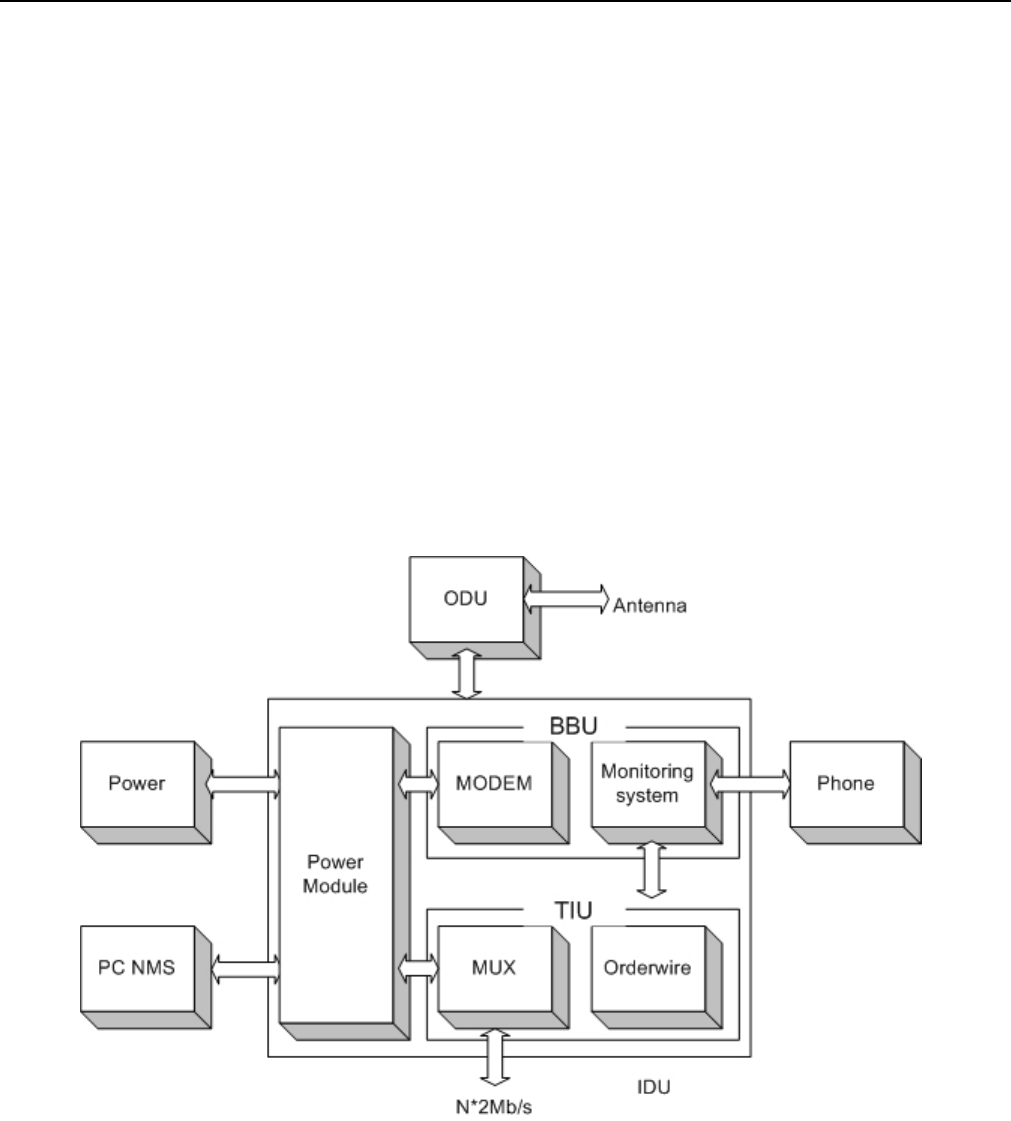
Figure 2-1 E1 IDU Block Diagram
2.3.2 System Principle
N number of E1 signals, digital service, 9600bps system net control and 9600bps data relays multiplexed in a
multiplexer to a specific microwave frame code. After QPSK modulation, the system sends the transmission to
the ODU through an IF cable. It enter the ODU IF upstream balance circuit, upconverter, power amplifier, filter,

E1 Spread Spectrum Radios
2-3
duplexer and are then transmitted out through the antenna system.
The opposite terminal’s antenna system receives the microwave signals and passed on to the multiplexer, LNA,
downconverter, filter, dual conversion and the IDU. In the IDU, it passes through the QPSK demodulator to
recover the microwave frame signal. This frame signal is then processed through demultiplexer to recover the
N number of E1 signal and other service signal.
The monitor unit of the equipment is controlled by the CPU (central processing unit) to function as: monitoring,
controlling, dispatching, alarming, processing and signaling etc. Based on the statistical result of BER test in
the multiplexer, we have 10-3BER, 10-6BER and frame loss signals.
Digital service adopts the Analog rule of 64kbps and PCM (Pulse Code Modulation) for service relay, complete
address selection and full address function. Simulating transfer completes the multiple categorized public
affairs connection. The dialing mode adopts DTMF system.
System network management uses PC machine of Intel Pentium II and above operating system.
Under Microsoft Windows environment’s using Arbeit NMS, it is possible to relay between equipment, collect
all the equipment’s status in the network and select records for printing. The introduction of animation design
makes the network topology and selected equipment’s status crystal clear.

E1 Spread Spectrum Radio
s
3-1
3 Technological Characteristics
Traditional digital microwave equipment generally transmits E1 signal only, so there is always the need to
apply for frequency channel use because of technological limitations.
In recent years, there is a dramatic change in the structure, composition and application of digital microwave
communicative equipment. The traditional system of transmission has been changed to the integration of
transmitter and receiver as well as from fixed frequency to the possibility of frequency conversion from low to
high frequency band. In view of the high frequency digital microwave communication system’s new changes
and additional newer characteristics, we had already improved the traditional system to a great length
E1 Spread Spectrum Radios has the following technological characteristics:
-- High frequency band: 2.4、5.8GHz
-- Complete capacity: 2*E1、4*E1s、8*E1、16*E1
-- Simplified set up: The ODU’s Signal Indicator indicates the correct angle adjustment of the antenna
-- Flexible interface: suitable for multiple network and service links
-- IDU and ODU unit connected by a single IF cable up to 200m length, thereby, decreasing the RF
transmission loss and increasing the receiving signal-to-noise ratio (S/N)
-- Channel conversion function reduce the cost of large and flexible network deployment
-- Digitally advanced QPSK de/modulation
-- Powerful monitoring function: simple and easy to operate LCD display. With the overall status display and
loopback test function, users can easily maintain the system without the need of special equipment to
ascertain any malfunction
-- Improved network management system suit a lot of different network topological structure. It can manage up
to 255 station equipments and also extend the monitoring support to other microwave equipments
-- Quick and easy installation
E1 Spread Spectrum Radios
4-1
4 Product Description
4.1 Indoor(IDU)/Modem
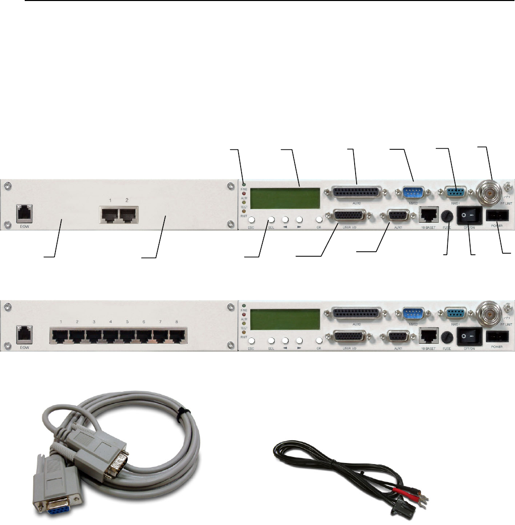
Figure 4-1 Front Panel (2E1,RJ-48)
Figure 4-2 Front Panel (8E1,RJ-48)
Interface Cable Power Cord
Figure 4-3 Accessories
4.1.1 General Description
A. Service Phone Interface(EOW): Service phone between the stations. Insert the RJ-11 of any general
phones and dial the IDU EOW number. If there are more than one equipments in the same network, you
may dial “***” for group connection. All the phones in the network will ring.
B. Symmetric E1 connector (RJ-48): 2E1: 2*RJ-48、4E1: 4* RJ-48、8E1: 8* RJ-48、16E1: 16* DB-25
(asymmetric). In this manual, we have taken 4E1 equipment as an example for easy explanation.
C. LED: FINE indicates normal working condition. ALM indicates critical alarming condition. RMT indicates
A
B
CE
J
FG H
KLM NO
D
E1 Spread Spectrum Radios
4-2
remote unstable condition. TEST indicates system undergoing loopback test.
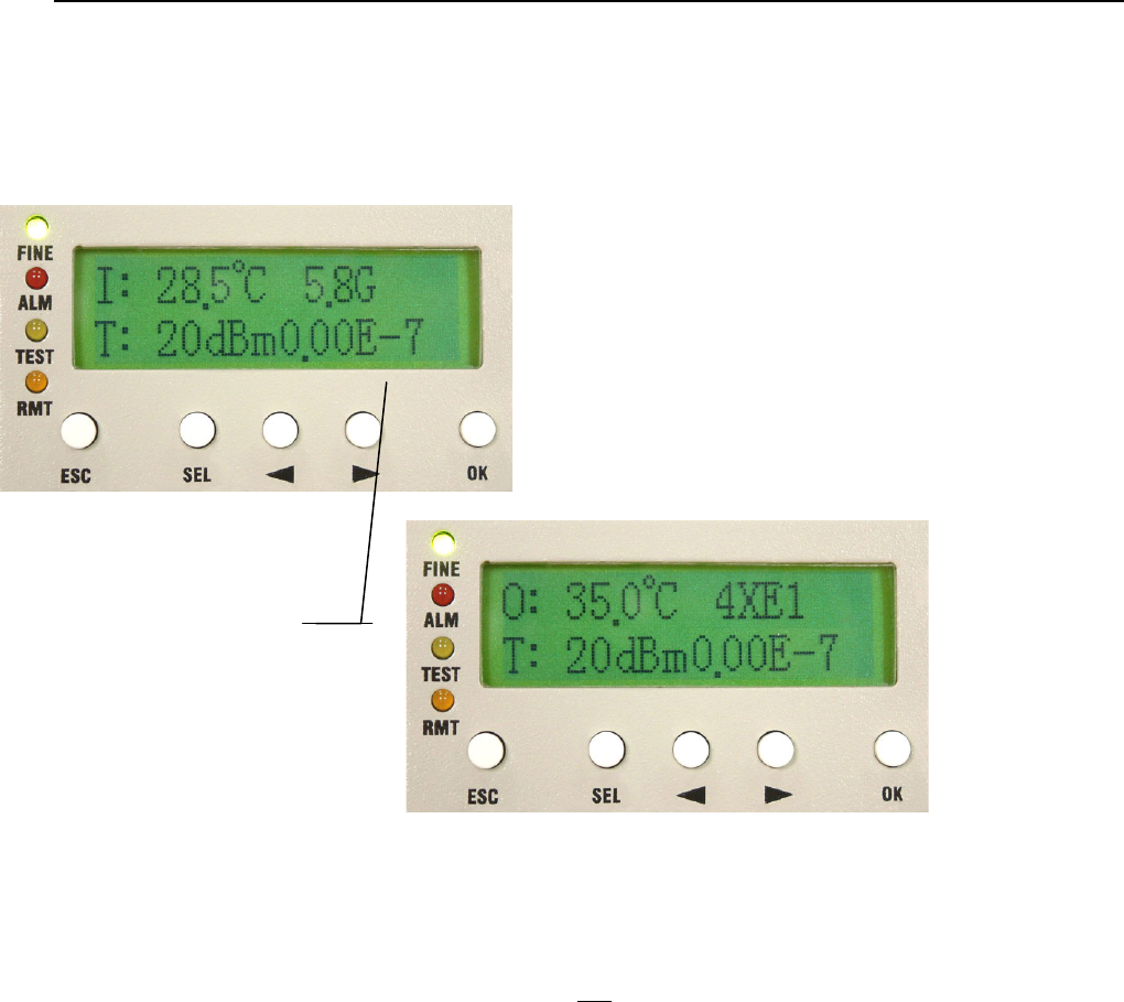
D. LCD Display: Display the normal working temperature; transmit/receive power, capacity, frequency, BER
and system time.
Figure 4-4 LCD Display
E. Data Port 2 (AUX2): When local equipment should communicate with remote site equipment for simple
data file transmission or online text communication, this port could be used.
F. String Port (NMS2): When there are more than two sets of equipments in the local stations, connect the
IDU-NMS2 of this equipment to the IDU-NMS1 of the other equipment. When the NMS2 are connected,
only one of the service phones is working.
G. Monitor port (NMS1): Connect the COM1 or COM2 (RS-232) of the computer to this port or act as a
connection between more stations.
H. IF Port (N-Type 50Ω): Transmission includes transmitter 310MHz, receiver 70MHz, monitor
11.0592MHz, DC -48V/0.5A. Maximum transmission of 100m possible when using RG-6 cable.
Maximum transmission 200m possible when using RG-8 cable.
I. Grounding
J. LCD Function Keys: Under normal working condition, LCD back light will glows if any button is pressed,
If there is any alarm, the LCD backlight will automatically glows for 2 minutes and display the alarming
status. The buzzer goes off until it is turn off. To shut off the buzzer temporarily, press SEL.
LCD Display refreshes
every 1~2 second
E1 Spread Spectrum Radios
4-3
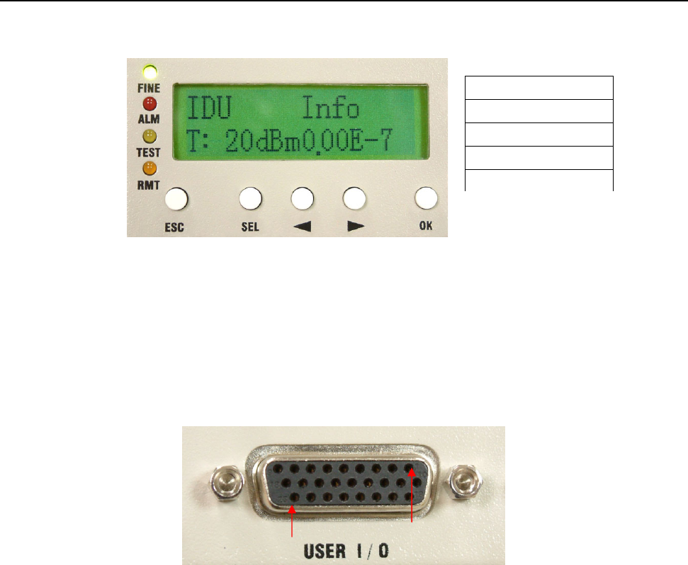
Figure 4-5 LCD Function Key
K. User I/O Port: Allows users to fully monitor the central controlling room from the local station. For
example: In the absence of human control in the remote stations, the central controlling server is able to
receive all the data like fire alarms, power supply etc. It can also control the light switches, oil switches
etc. This function totally realizes the possibility of intelligent management. Altogether, there are 8 input
ports and 4 output ports.
Figure 4-6 User I/O Port DB-26 pin
L. Data Port 1 (AUX1): Use the Windows OS’s HyperTerminal function (9.6K). Connect the COM1 or
COM2 (RS-232/DB-9) of two-end computers to this port for simple file and data transmission.
M. Fuse: 250V/2A
N. Power switch
O. Input power port: -48V/1A DC
ESC Exit
SEL Select
◄ Left Arrow
► Right Arrow
OK Confirm
1
26
E1 Spread Spectrum Radios
4-4
4.2 Outdoor(ODU)/RF Unit
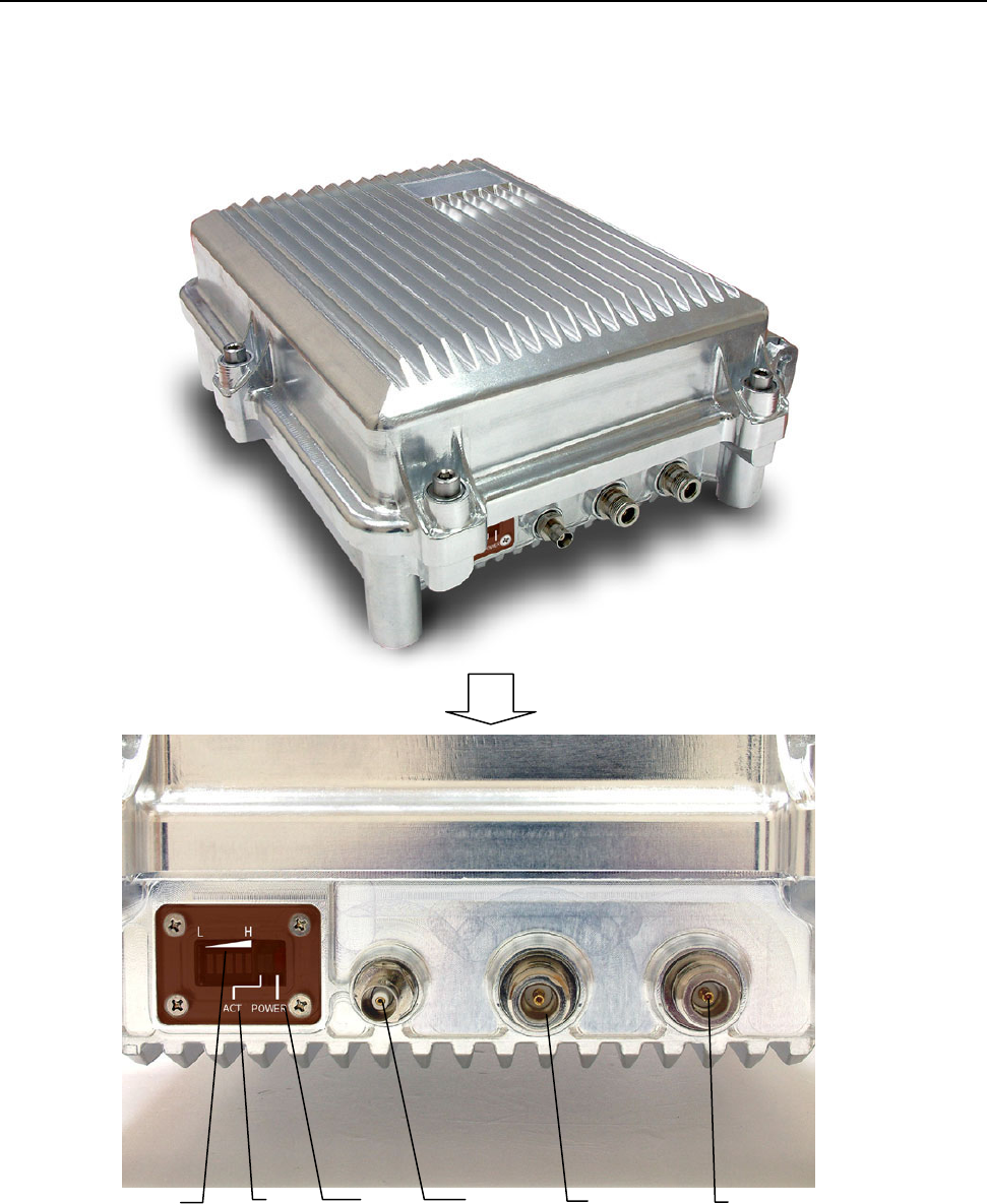
Figure 4-7 ODU Display
4.2.1 General Description
A. Antenna Alignment Indicator: If there is no electric meter during set up, this indicator helps to define the
antenna alignment. Higher the signal strength indicates better antenna alignment.
E
D C F
B
A
E1 Spread Spectrum Radios
4-5
B. ACT Indicator (ACT): This indicator lights up on receiving signal from the opposite device.
C. Power Indicator: ODU’s power indicator light. When all the connecting cables are well connected, switch
ON the IDU’s power. The ODU will provide a power of -48V/0.5A through the IF cable of the IDU.
D. Receive Signal Strength Indicator (RSSI): For better antenna alignment between two terminals at a
longer distance, please rotate and open the BNC 50Ω. Use an electric meter to measure the RSSI
voltage. Weak voltage indicates weak signal received, strong signal indicates the most accurate angle
position.
E. Antenna Interface (TO ANT): Use N-type coaxial cable to connect to the Antenna.
9 At the ODU’s E and F interface, please entwine waterproof tape at the connection point so as to prevent
rainwater or moisture from the device. Natural damage is not warranted.
F. IF Port (N-Type 50Ω): Transmission includes transmitter 310MHz, receiver 70MHz, monitor
11.0592MHz, DC -48V/0.5A. Maximum transmission of 100m possible when using RG-6 cable.
Maximum transmission 200m possible when using RG-8 cable.
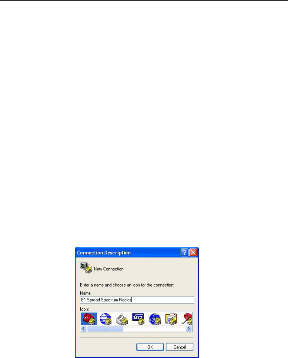
4.3 Date Port Guide
The given example uses Microsoft Windows XP. For other OS, please assess accordingly.
STEP 1: Click Start Æ Programs Æ Accessories Æ Communications Æ HyperTerminal. In the
Connection Description window enter name in the Name: window and click OK to continue.
Figure 4-8 Data Port Settings (1)
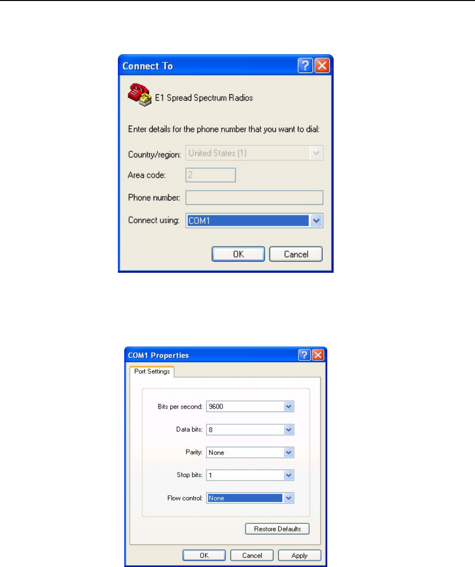
STEP 2: In the Connect To window click on the down arrow for the Connect using: drop down menu
selections and select the COM Port where the modem is connected. In this example, the modem is
connected to COM1. The other fields in the window will gray out and the COM1 is now set. Click OK to
E1 Spread Spectrum Radios
4-6
continue.
Figure 4-9 Data Port Settings (2)
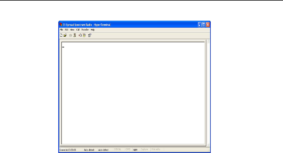
STEP 3:The COM1 Properties window will appear. Set the Bits per second to 9600; Data Bits to 8;
Parity to None; Stop Bits to 1; Flow Control to None; and click OK to continue.
Figure 4-10 Data Port Settings (3)
E1 Spread Spectrum Radios
4-7
Figure 4-11 Data Port Settings (4)

E1 Spread Spectrum Radios
5-1
5 Interface
5.1 Front Panel
E1 interface can be of unbalanced 75Ω BNC or balanced 120Ω RJ-48. User’s can flexibly choose either of
these two interface equipment.
Besides the standard E1 interface, the equipment also provides service, monitor, data, User I/O and control
port. This allows the user to conveniently fully monitor the control room through this equipment. This
equipment has 8 input ports, plus 4 output ports.
5.1.1 Engineering Order Wire(EOW)
Service phone plays a significant role in underdeveloped and mountainous areas. Other than possessing the
function of selective and entire calling, it also has the following most distinguishing features: whole tone service
like dial tone, engage tone, out-of-order tone etc. Users do not feel much difference in using service phone
from general phone service because it is very user-friendly and fits all the demands of users. We can also use
textmenu to set up the service phone numbers.
9 Dial tone: When dialing from the local station, you’ll hear the same dial tone as any general telephones
Engage tone: The repeating ring tone is 2 ± 0.2s ring and 4 ± 0.4s break
Ring tone: Same as the engage tone
Out-of-order tone: When there is an out-of-order service or lost of signal service, it will ring the
out-of-order tone at 500 ± 50ms, 230ms ± 70ms and then break connection
Busy tone: Continue to redial at an exchange of 500ms ± 50ms
E1 Spread Spectrum Radios
5-2
5.1.2 LCD Description
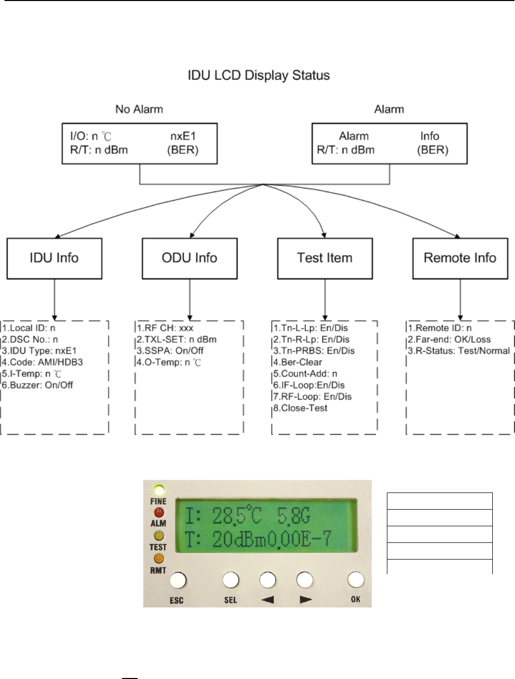
Figure 5-1 IDU Function Tree
Figure 5-2 LCD Function Keys (1)
For the LCD to fully display the system’s status and perform those simple set up operations, try to make use of
the above-mentioned five function keys to carry out the operations.
Under normal condition, the LCD displays as below:
ESC Exit
SEL Select
◄ Left Arrow
► Right Arrow
OK Confirm
E1 Spread Spectrum Radios
5-3
Figure 5-3 LCD Function Keys (2)
1st line of the LCD display – refreshes every alternate 1~2 seconds.
Left hand side: IDU temperature. O-Temp: xx.x℃ stands for ODU temperature.
Right hand side: 4XE1 stands for the system capacity. 2.4/5.8G stands for the operating frequency.
2nd line of the LCD display – refreshes every alternate 1~2 seconds.
Left hand side: R: xxxdBm stands for the real-time online receiving power. T: xxxdBm stands for the real-time
online transmitting power.
Right hand side: On the right hand side, it displays the bit-error rate (BER).
Note: Bit Error Rate (BER): The conversion formula for accumulated bit errors is:
BER = (n/EN*S).
where, n = number of times of bit error;
EN = rate of the equipment, E1’s rate is 2.048M;S = running time ( in seconds).
For example:
Present bit error times is 3, running time is 2 minutes and system interface is E1
BER = (3 / (2.048 * 106 * 2 * 60)) = 1.22∴ * 10-8
Present bit error times is 1000000, running time is 4 minutes and system interface is E1
BER = (566 / (2.048 * 106 * 4 * 60 * 60)) = 3.39 * 10∴-5
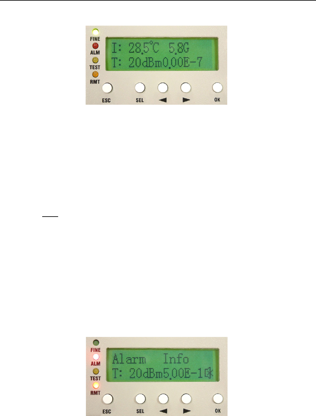
Under alarm condition, the LCD displays as below:
Figure 5-4 Alarm Status
E1 Spread Spectrum Radios
5-4
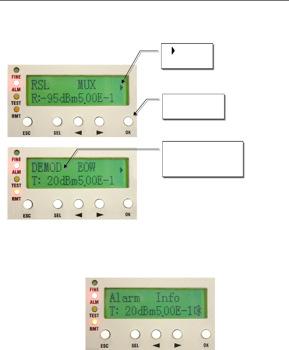
Now press the OK button of the panel. It will display the alarm message. Press the Right/Left button of the
panel. The LCD displays the current alarm message. Please refer to section 9.2.For example:
Figure 5-5 Alarm Function
Whenever there is an alarm, the LCD back light will light for 2 minutes and the buzzer sounds goes off. Other
than removing the alarm status or switching off the buzzer status, we can switch off the buzzer by pressing the
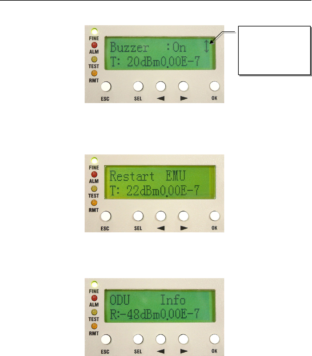
SEL button. To switch on the buzzer, please enter the IDU Info/Buzzer: On/Off.
Figure 5-6 Buzzer OFF
1. Message in
the next page
2. Press to read the
next page
3. The first line of the LCD
shows the line shifts
towards the left
E1 Spread Spectrum Radios
5-5
5.2 LCD Operation
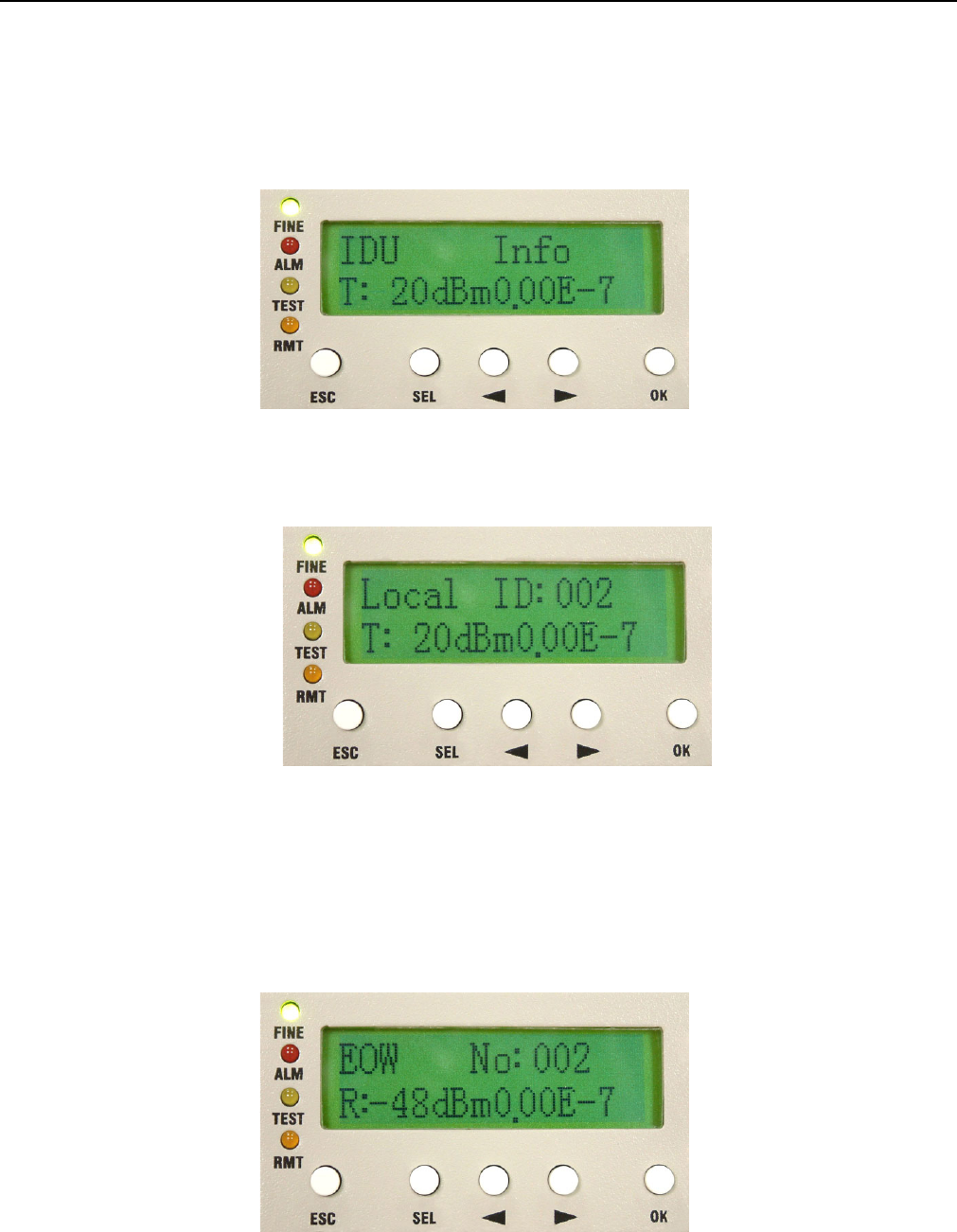
5.2.1 IDU Info
Figure 5-7 IDU Info
A1. Local ID: n(In IDU info, press OK to enter Local ID)
Figure 5-8 Local ID
A2. EOW No.: n (as in A1 display, press ► )
Display the local equipment’s service phone number EOW, Engineering Order Wire. In the same link route
system, there can be a maximum series connection of 255 service phone. NMS software is used for the
service phone’s initial set-up.
Figure 5-9 EOW No:n
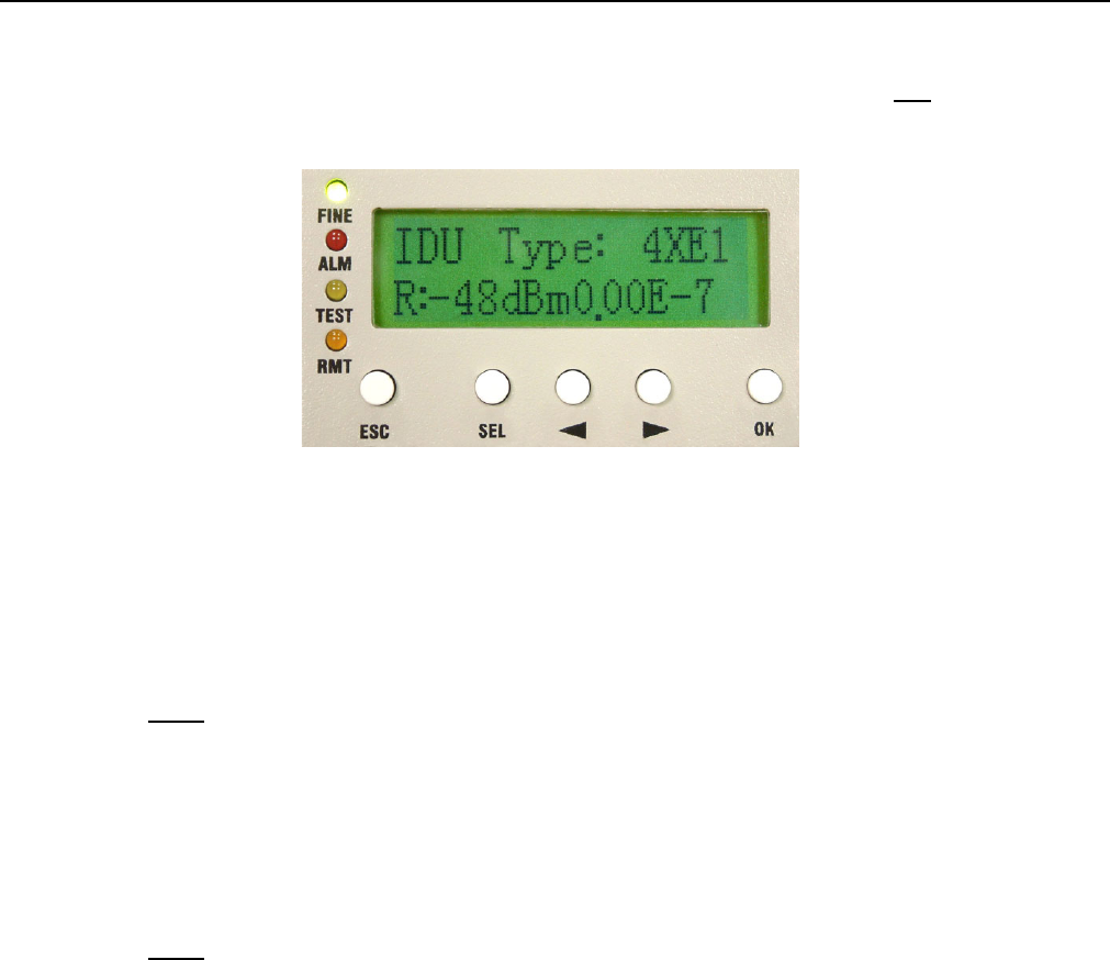
A3. IDU Type: nXE1 (as in A2 display, press ► )
E1 Spread Spectrum Radios
5-6
Display the number of E1 capacity. If it displays 4XE1, it means that the equipment has four E1 interface. In
this manual, we have taken 4E1 equipment as an example for easy explanation.
Figure 5-10 IDU Type: nXE1
A4. Code: AMI/HDB3 (as in A3 display, press ► )
Display the code used. After pressing the OK button, use the Right/Left button to choose either of the two
codes: AMI or HDB3.
Note: AMI Code→
AMI (Alternate Mark Inversion) is a synchronous clock encoding technique which uses bipolar pulses to
represent logical 1 value. A logical 0 is represented by no symbol and a logical 1 by pulses of alternating
polarity.
Example of AMI encoding:
The pattern of bits " 1 0 0 0 0 1 1 0 " encodes to "+ 0 0 0 0 - +
Note: HDB3→
HDB3 (High Density Bipolar Order 3 Encoding) is based on Alternate Mark Inversion (AMI), but extends
this by inserting violation codes whenever there is a run of 4 or more 0's. This and similar (more complex)
codes have replaced AMI in modern distribution networks. The purpose of this is to prevent long runs of
0's in the data stream, sometimes called a "run length limited" code. Encode any pattern of more than
four bits as B00V, where B is a balancing pulse. The value of B is assigned as + or - , so as to make
alternate "V"s of opposite polarity. The receiver removes all Violation pulses, but in addition a violation
preceded by two zeros and a pulse is treated as the "BOOV" pattern and both the violation and balancing
pulse are removed from the received bit stream. This restores the original bit stream.
HDB3 is one of CCITT’s recommended uses.
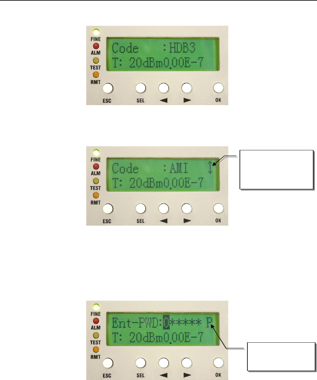
For example: switching E1 transmitted HDB3 code to AMI code
1. Enter IDU Info/Code: sub-menu. Press OK.
E1 Spread Spectrum Radios
5-7
Figure 5-11 Code:HDB3/AMI
2. Press the Right/Left button to change HDB3 to AMI. Press OK.
Figure 5-12 Code Switch (1)
3. Enter the password verification. Enter the 6-digits system password (preset password is 000000). Use SEL
to change between different functions. Press OK.
9 P = Place; A = Adjust
Figure 5-13 Code Switch (2)
This sign allows the
use of Right/Left arrow
to select the functions
P mode: use the
Right/Left button to
E1 Spread Spectrum Radios
5-8
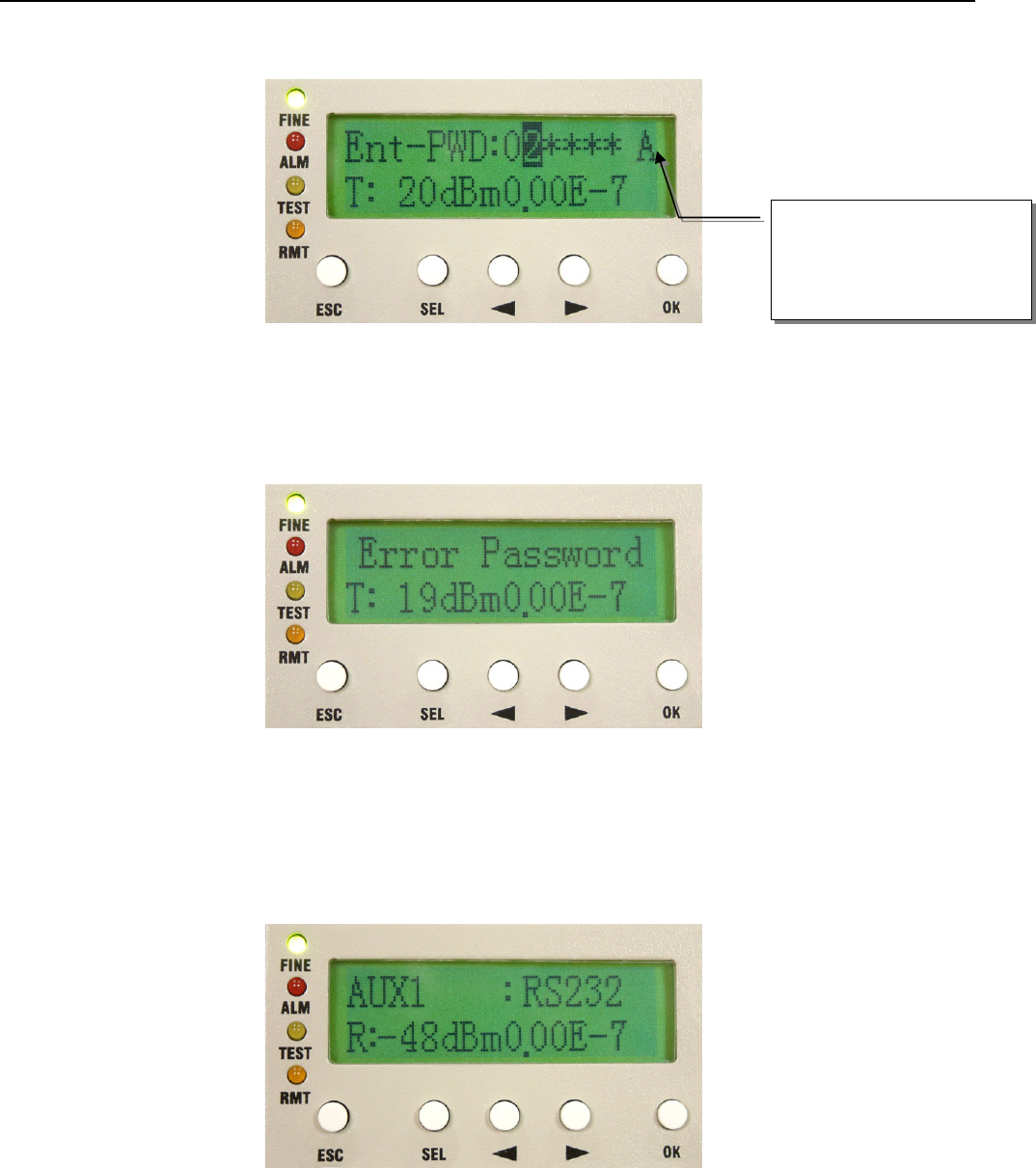
Figure 5-14 Code Switch (3)
4. Error Password is displayed on entering the wrong password. It will not save the wrong password. This will
be display for 5~10sec. and then return to the main function display.
Figure 5-15 Code Switch (4)
A5. AUX1: RS232/RS422
This protocol is used to transfer simple file and data transmission between local and remote equipment
through RS232 or RS422.
Figure 5-16 AUX1:RS232/RS422
A6. AUX2: ASY-CH/SYN-CH
Select either ASY-CH for asynchronous channel or SYN-CH for synchronous channel.
A mode (0~9) digits: use
the Right/Left button to
select
E1 Spread Spectrum Radios
5-9
Figure 5-17 AUX2:ASY-CH/SYN-CH
A7. I-Temp: n℃
Display the local ODU’s working temperature.
Figure 5-18 I-Temp:n℃
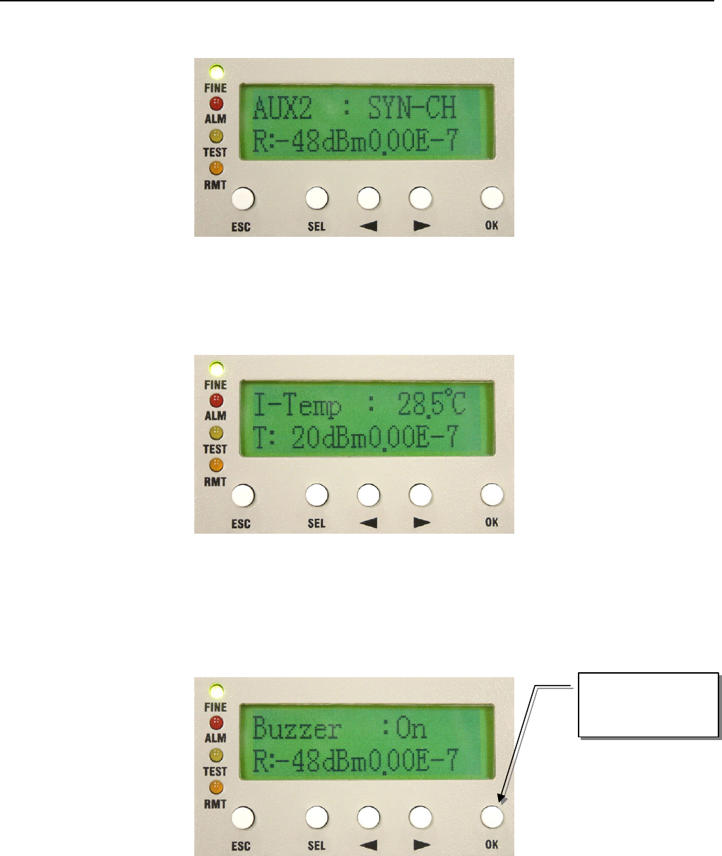
A8. Buzzer: On/Off
Display the buzzer On/Off switch.
Ex:
Press OK to enter
the setup function
E1 Spread Spectrum Radios
5-10
Figure 5-19 Buzzer:On/Off
A8. Restart EMU: Y/N
Restart the E1 Radios system.
Figure 5-20 Restart EMU:Y/N
5.2.2 ODU Info
Figure 5-21 ODU Info
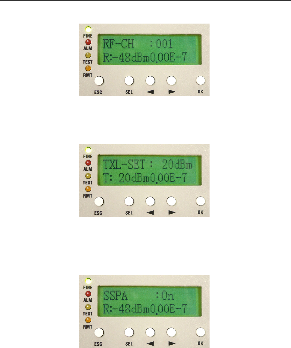
B1. RF-CH: n
Display the ODU’s current RF channel.
This sign shows you
may use the
Right/Left arrow to
select OFF. Press OK.
E1 Spread Spectrum Radios
5-11
Figure 5-22 RF-CH:n
B2. TxL-SET: ndBm
Display the transmitting power level.
Figure 5-23 TxL-SET:ndBm
B3. SSPA: On/Off
To set the PA to On/Off. Press the OK button after selection. Use the Right/Left button to select On/Off, then
press OK.
Figure 5-24 SSPA:On/Off
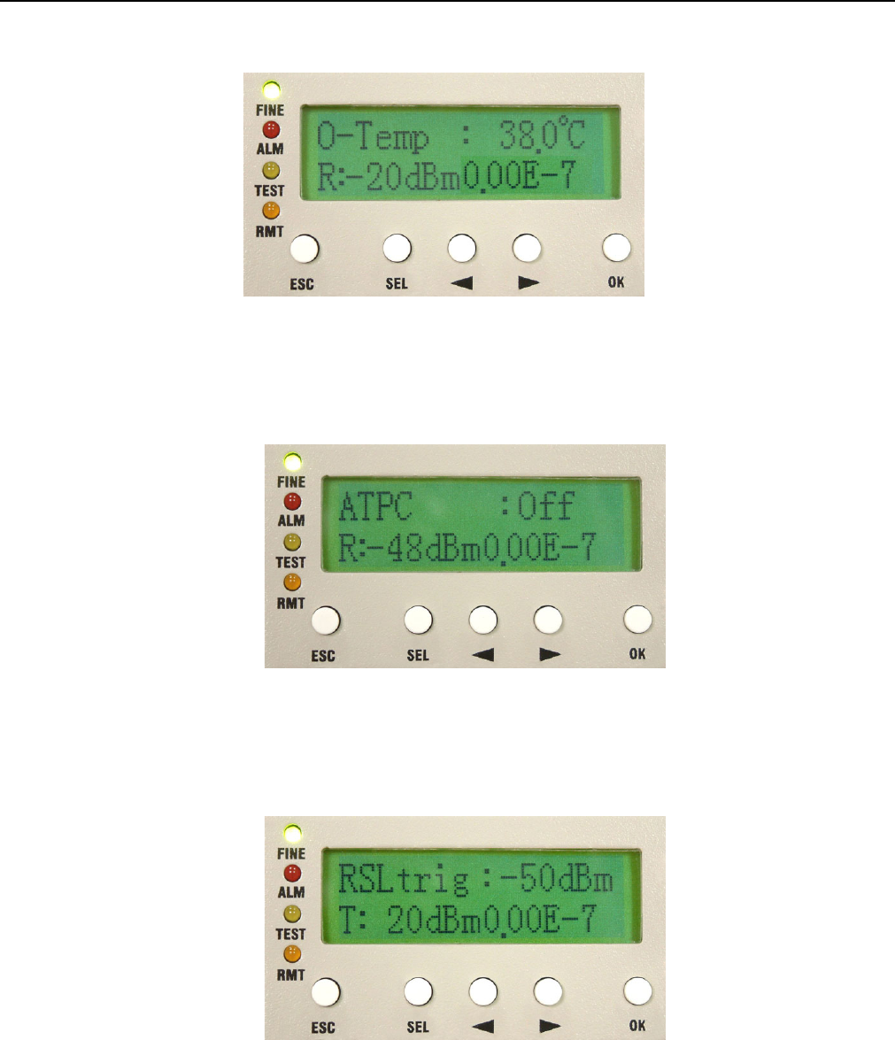
B4. O-Temp: n℃
Display the local ODU’s current working temperature.
E1 Spread Spectrum Radios
5-12
Figure 5-25 O-Temp:n℃
B5. ATPC:Off
Display ATPC On or Off. The function reserves for future usage now.
Figure 5-26 ATPC:Off
B6. RSLtrig:n dBm
Display the lowest RSL alarm trigger level. The function reserves for future usage now.
Figure 5-27 RSLtrig: n dBm
E1 Spread Spectrum Radios
5-13
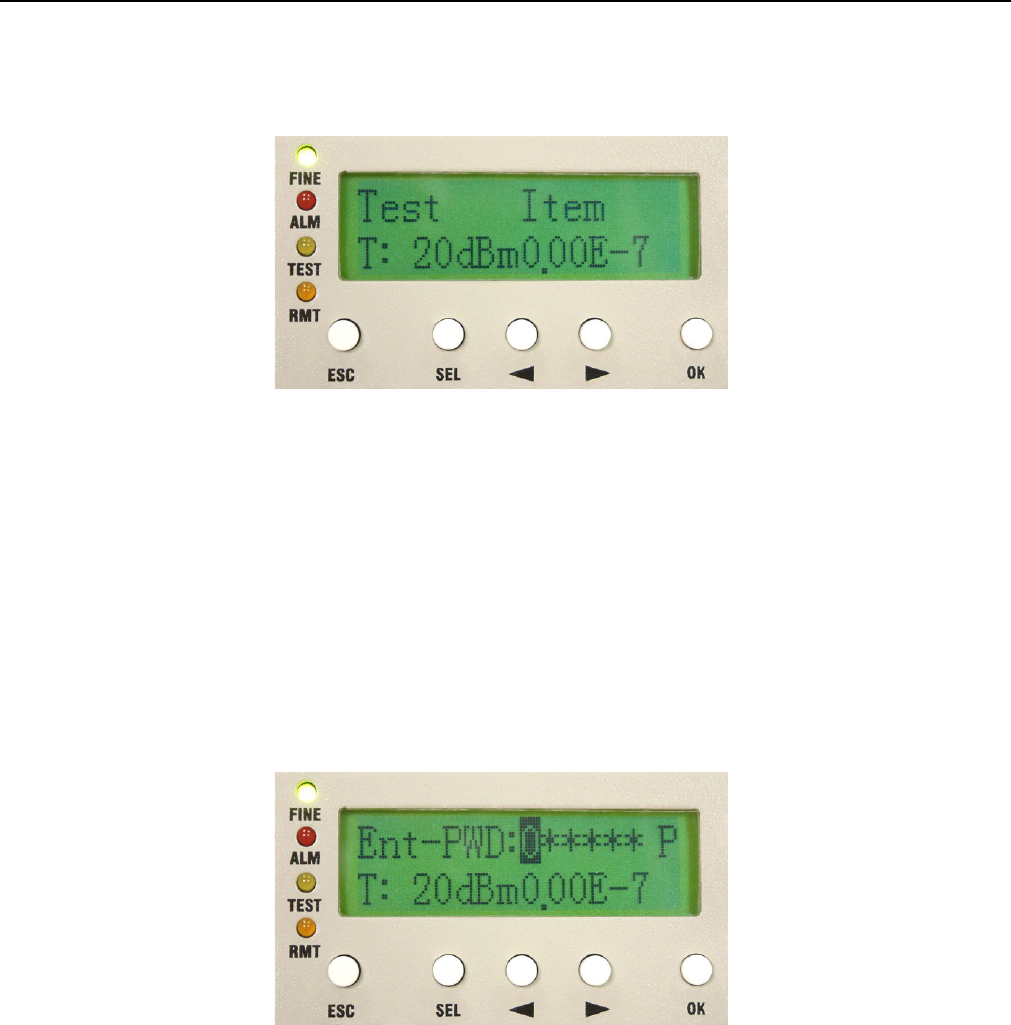
5.2.3 Test Item
Figure 5-28 Test Item
This item allows you to enter Loopback mode.
9 System allows only one kind of loopback at a time.
Enter Test Item. Press OK. Enter the password verification. Enter the 6-digits system password. Use SEL to
change between different functions.
9 P = Position; A = Adjust; Press OK.
Figure 5-29 Enter Password
9 The default password is “000000”.
C1. Tri-Loc-Loop\Tn-L-LP: En/Dis
Perform Local Loopback test in the local end for the convenience of testing the equipment’s stability. Use the
Right/Left button to select the T1~Tn tributary of the local E1 interface. Press OK. The Right/Left button is also
used for selecting En/Dis (En=Enable/Dis=Disable). This is used along with E1 transmission tester for E1
interface test.
E1 Spread Spectrum Radios
5-14
9 This function can not be used with its own PRBS function for testing.
For example:
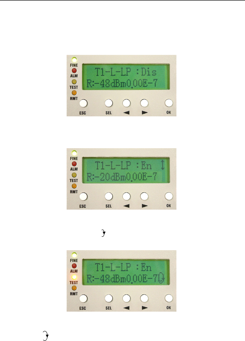
1. To set the tributary 1 of E1 to Local Loopback. Enter \TEST Item\ Tri-Loc-Loop \T1-L-LP. Press OK.
Figure 5-30 Tn-L-LP:En/Dis (1)
2. Use the Right/Left button to change Dis (Disable) to En (Enable). Press OK.
Figure 5-31 Tn-L-LP:En/Dis (2)
Local End: Tributary 2 in Local Loopback. appears at the right bottom of the LCD. TEST led gives an orange
glow.
Figure 5-32 Tn-L-LP:En/Dis (3)
Remote End: appears at the right bottom of the LCD.
L
E1 Spread Spectrum Radios
5-15
Figure 5-33 Tn-L-LP:En/Dis (4)
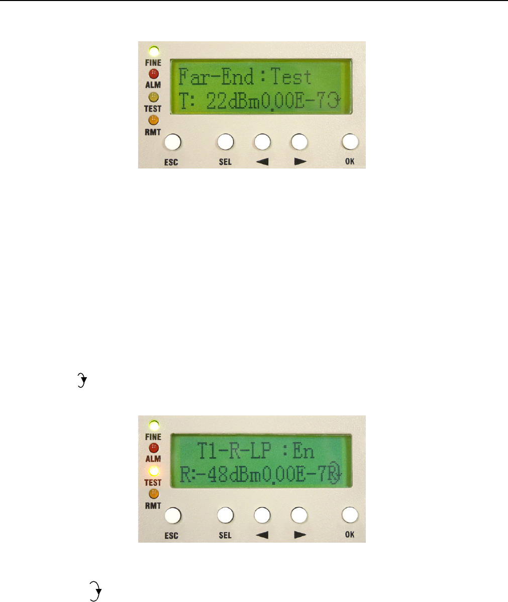
C2. Tri-Rem-LP\Tn-R-LP: En/Dis
Perform Remote Loopback in the remote end for the convenience of testing the link’s stability. Use the
Right/Left button to select the T1~Tn tributary of the remote E1 interface. Press OK. The Right/Left button is
also used for selecting En/Dis (En=Enable/Dis=Disable). This is used along with IDU PRBS (given in C3) for
BER test as well as with E1 transmission tester for E1 interface test.
9 While executing PRBS, the local and remote equipment will display the accumulated bit error.
For example:
Local End: appears at the right bottom of the LCD means in Remote Loopback. TEST led gives an orange
glow.
Figure 5-34 Tn-R-LP:En/Dis (1)
Remote End: appears at the right bottom of the LCD. TEST led gives an orange glow.
R
E1 Spread Spectrum Radios
5-16
Figure 5-35 Tn-R-LP:En/Dis (2)
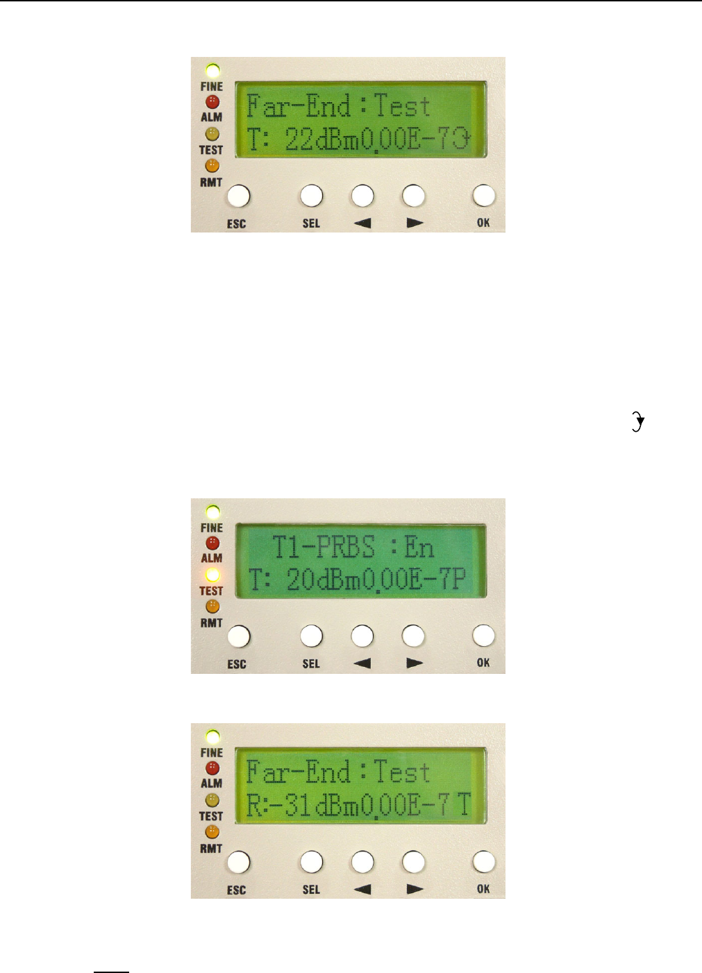
C3. Tri-TX-PRBS\Tn-PRBS: En/Dis
Press the Right/Left button to enter PRBS tributary test. Use Pseudo Random Code for E1 signal transmission
test along with the Remote Loopback, normal link equipment and the testing equipments to test the stability.
Press OK. Use the Right/Left button to select Enable/Disable. Press OK. On using this function, the LCD will
display the accumulated BER.
When Tributary 3 is in Remote Loopback (TEST led is orange). Open tributary 3 PRBS test. Now will
appear at the right bottom of the LCD. Remote end’s TEST led will turn orange too with “T” display on the front
panel LCD.
Remote End:
Figure 5-36 Tn-PRBS:En/Dis
Note: Pseudo-Random Bit Sequence (PRBS):
P