K Best Technology 5113R E1 Spread Spectrum Radios User Manual
K-Best Technology Inc. E1 Spread Spectrum Radios
Contents
- 1. User Manual 1
- 2. User Manual 2
- 3. User Manual 3
User Manual 3
E1 Spread Spectrum Radios
8-32
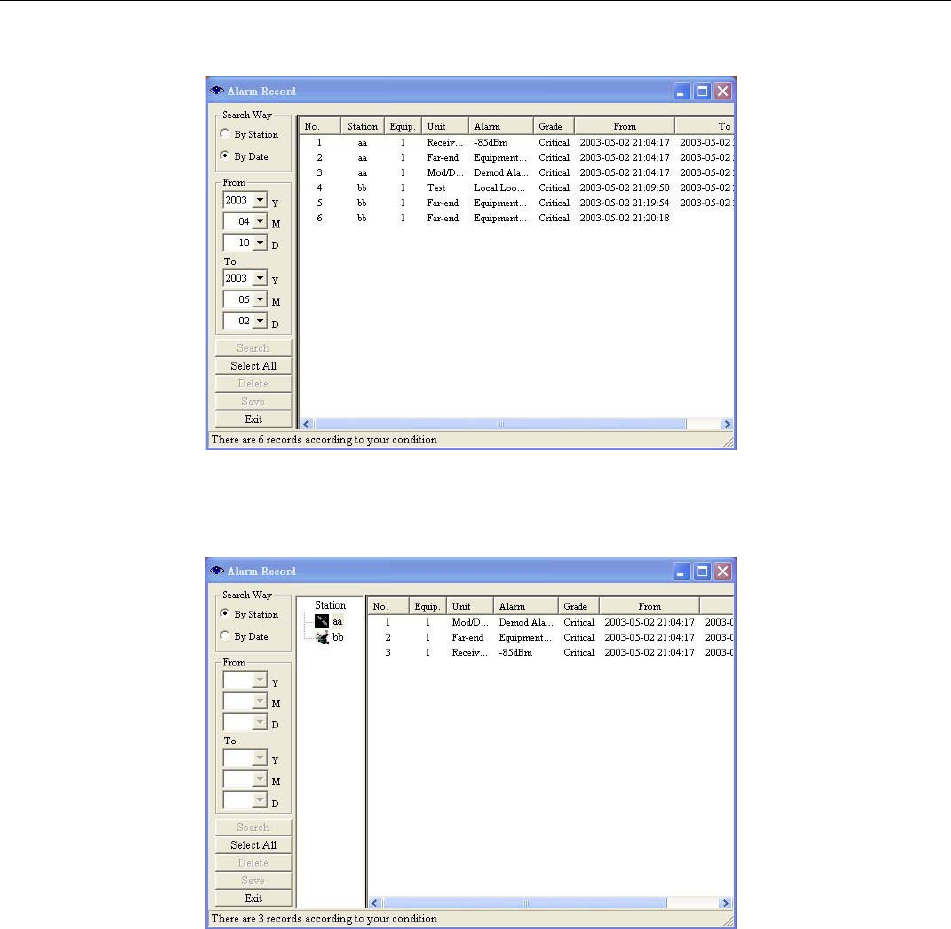
Figure 8-45: Sort by Date
Alarm record sorted by date: In Search Way, tick By Date,select From and To, press Search.
Figure 8-46: Sort by Station
Press Select All to select all the records. Press the Save to save the files. The following Save As window will
appear. Select the desired folder and file name. Press Save.
The file will be saved as *.txt or *.xls. You may use any word processor or Microsoft Office Excel to open the file.
E1 Spread Spectrum Radios
8-33
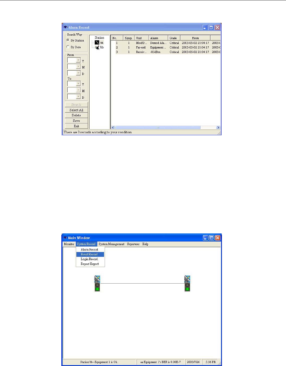
Figure 8-47: Select All Alarm Records
Single Deletion: Select the record you need to delete. Press Delete.
Overall Deletion: Press the Select All button and press Delete.
8.8.2 Event Record
In the Main Window, select System Record ÆEvent Record. Another initialization window will appear. For system
administrator’s easy management, Event Record records all the setting changes that had taken place.
Figure 8-48 Event Record (1)
E1 Spread Spectrum Radios
8-34
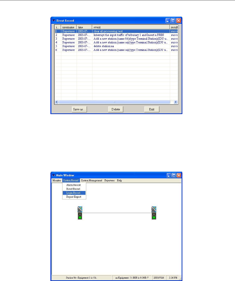
Figure 8-49 Event Record (2)
Save as…: buttons allows users to save single or all events as Excel files.
8.8.3 Login Record
In the Main Window, select System Record ÆLogin Record. Another initialization window will appear.
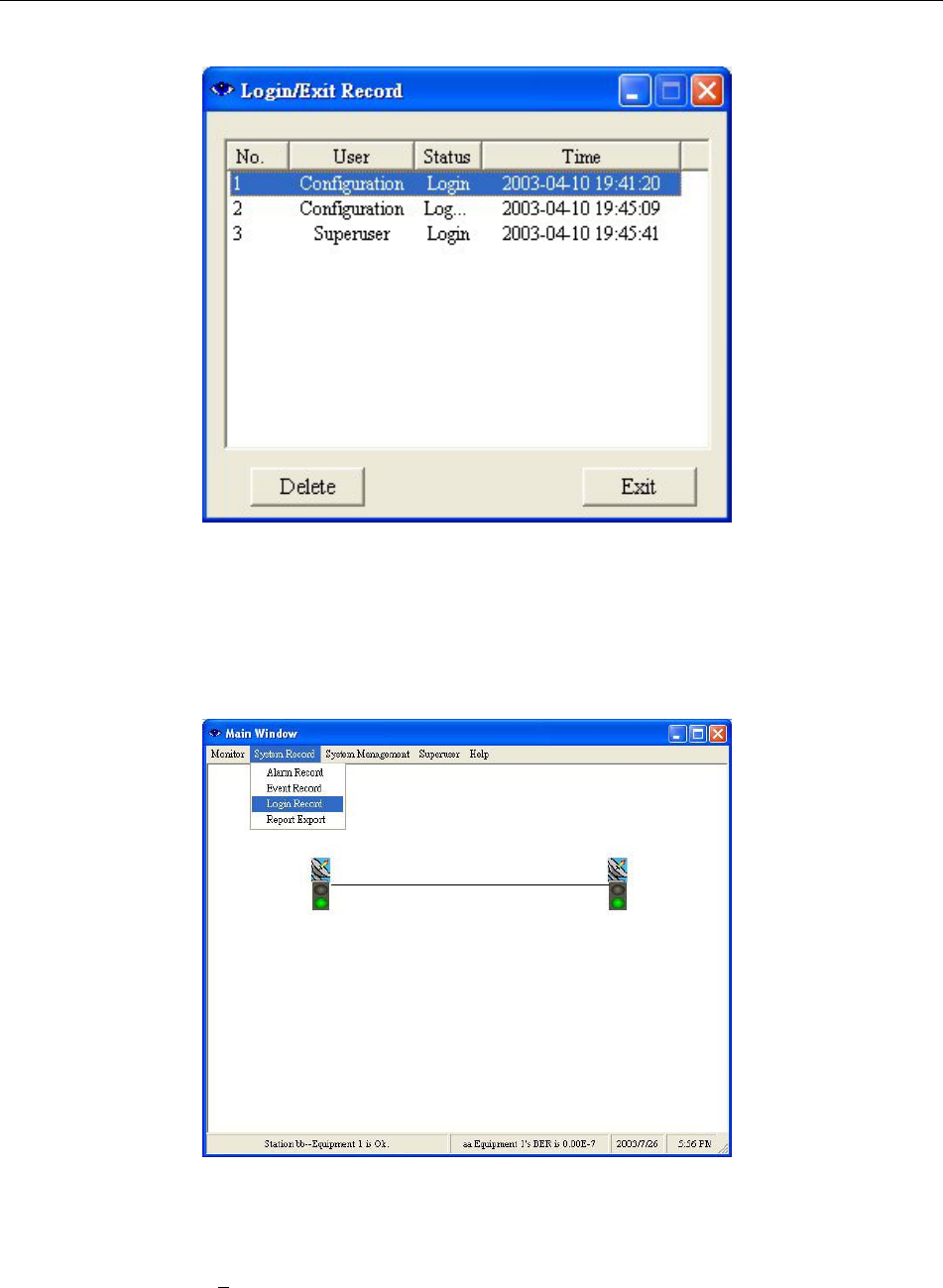
Figure 8-50: Login Record
Select the record you need to delete. Press Delete.
E1 Spread Spectrum Radios
8-35
Figure 8-51: Deleting Login Record
8.8.4 Report Export
In the Main Window, select System Record ÆRecord Export. Another initialization window will appear.
Figure 8-52: Report Export (1)
Report From/To: Enter the date for reports.
System Report: There are 5 kinds of reports - System ReportΕAlarm ReportΕIDU ReportΕODU ReportΕLink
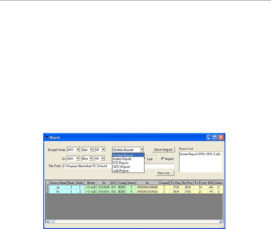
E1 Spread Spectrum Radios
8-36
Report.
System Report reports the system setting. Alarm Report reports all the alarms. IDU Report reports
the IDU’s setting and alarm. ODU Report reports the ODU’s setting and alarm. Link Report reports
all the links, the setting and alarm.
System Report and Alarm Report- can tick IDUΕODUΕLink as the source.
IDU ReportΕODU Report and Link Report – can tick SystemΕAlarm as the source.
Show Report: The reports are shown in the desired format from the date selected. Light blue represents
equipment’s status, light green represents IDU’s status, light yellow represents ODU’s status and
light orange represents the Link’s status.
Export List: Export List is used along with File Path and Save As… to open in Microsoft Office Excel.
File Path: The path for saving the reports are C:\Program Files\Arbeit.
Save As…: The file can be saved as a different name in different location. Press Save to complete.
Figure 8-53: Report Export (2)
E1 Spread Spectrum Radios
8-37
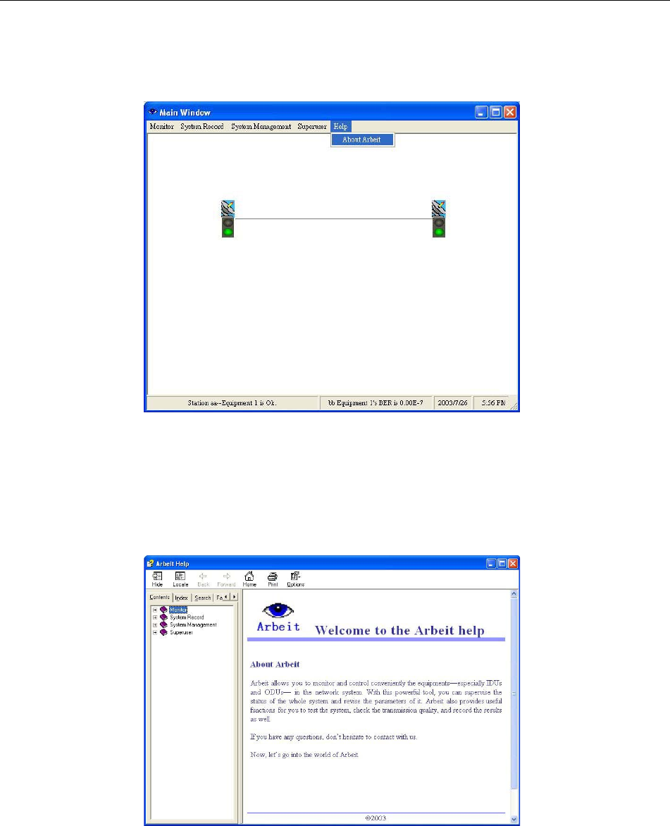
8.9 Help
Figure 8-54: Help
8.9.1 Help
Check all functions and explanations.
Figure 8-55: Function Explanations
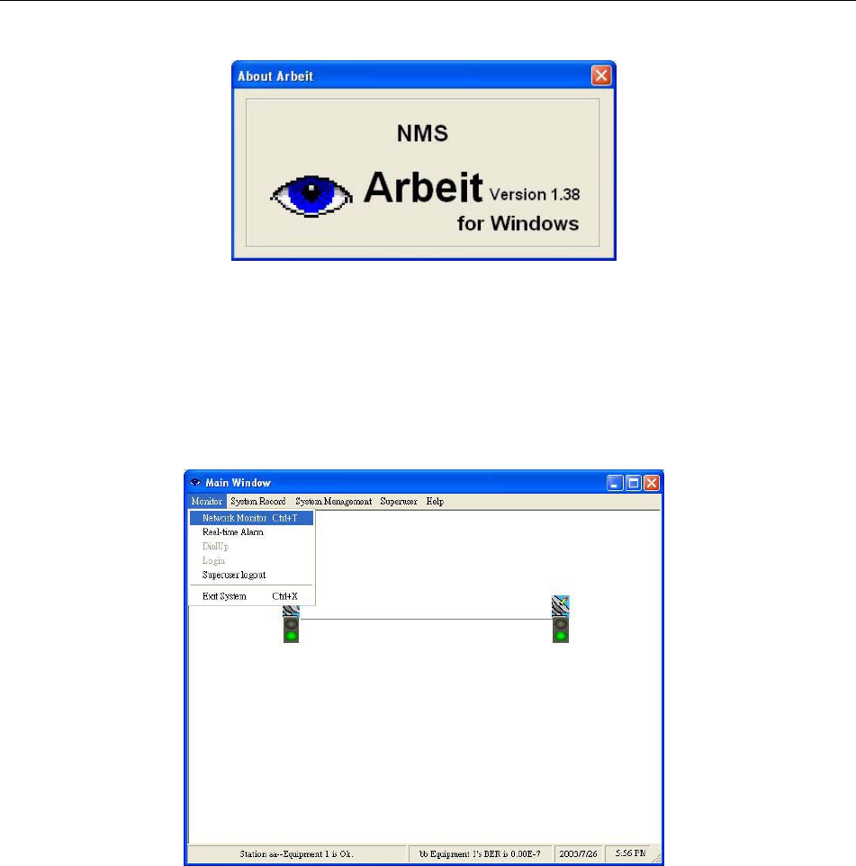
8.9.2 About Arbeit
Check Arbeit version.
E1 Spread Spectrum Radios
8-38
Figure 8-56 About Arbeit
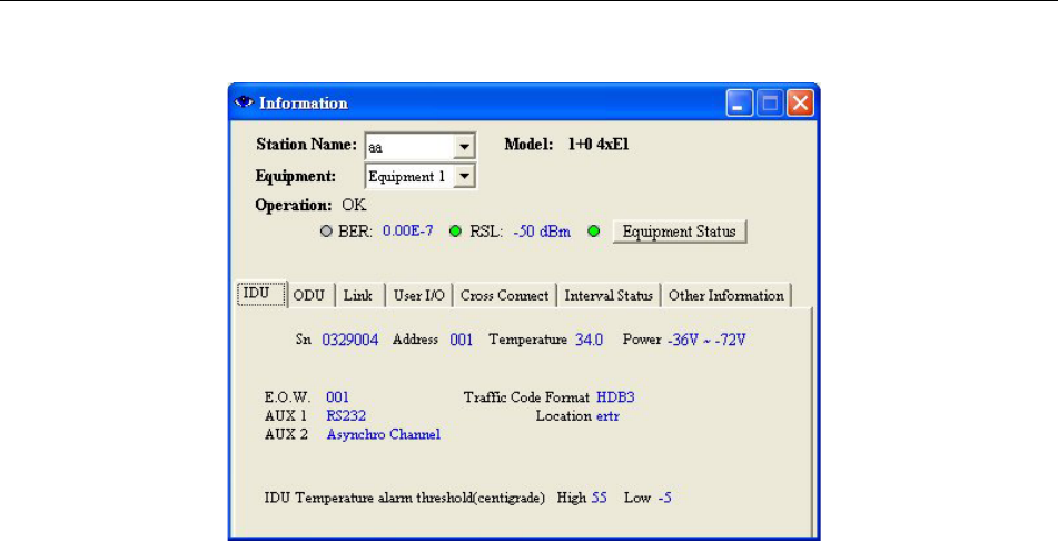
8.10 Monitor
8.10.1 Network Monitor
In the Main Window, select Monitor ÆNetwork Monitor.
Figure 8-57: Network Monitor (1)
E1 Spread Spectrum Radios
8-39
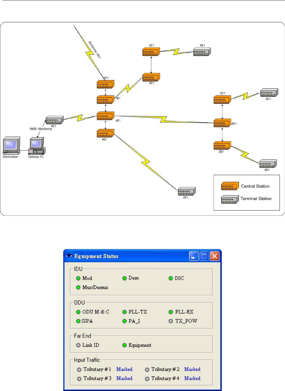
Figure 8-58: Network Monitor (2)
Network Monitor monitors all the station’s information in the same link e.g. Station NameΕEquipment No.ΕModelΕ
Far End Equipment etc. The following diagram shows the network links framework. It will display all information of
equipments in the same link.
SN: IDU’s serial number.
Address: Link ID address.
Temperature: IDU’s temperature.
Power: IDU’s receiving power.
E.O.W: service telephone number.
AUX1: AUX1 protocol.
AUX2: AUX2 mythology.
Traffic Code Format: communication mode.
Location: Location details.
IDU Temperature alarm threshold(centigrade)
E1 Spread Spectrum Radios
8-40
Figure 8-59: Network Monitor Links
In the above Network Monitor window, click on Equipment Status. The following dialog box appears:
E1 Spread Spectrum Radios
8-41
Figure 8-60: Equipment Status
Green = normal; Red = alarm; Grey = lost; Orange = test
Table 8-3: Equipment Status
Unit Status Description
AMP_M Amplitude Modulation alarm
Dem De/modulation cannot detect the pulse
EOW Abnormal service signal
Mux / Demux De/modulation alarm
IDU
PLL_MOD PLL lock failure
ODU M & C ODU control panel signal loss
ODU Power
PLL-TX RF TX local oscillator lock malfunction
PLL-RX RF RX local oscillator lock malfunction
SSPA Transmitting power alarm
PA_I PA alarm
ODU
TX_POW Transmitting power alarm and relay alarms if above ±2dB
Link ID Link ID error Far End
Equipment Remote equipment alarms
Tributary #n AIS IDU detect tributary n with all signal as 1
Tributary #n LOS IDU detected tributary n with no signal input
Input Traffic
Tributary #n no response IDU cannot detect any tributary status
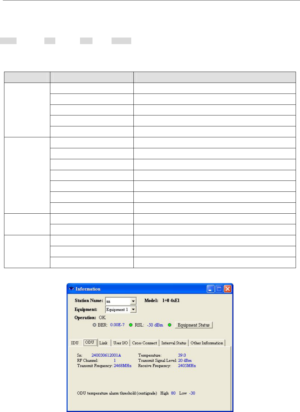
Under Information windows Æ ODU tab:
E1 Spread Spectrum Radios
8-42
Figure 8-61: ODU Status
Sn: ODU’s serial number.
RF Channel: working frequency channel.
Transmit Frequency: transmitting frequency channel.
Temperature: ODU’s temperature.
Transmit Signal Level: transmitting signal power level.
Receive Frequency: receiving frequency channel.
ODU temperature alarm threshold(centigrade)
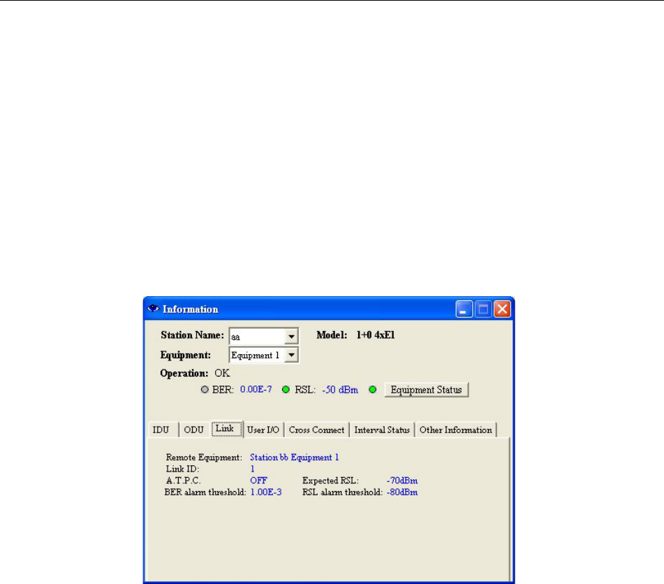
Under Information windows Æ Link tab:
Figure 8-62: Link Status
Remote Equipment: remote station name.
Link ID: link identification.
ATPC: automatic transmission power control.
BER alarm threshold: BER alarm setting.
Expected RSL: receive signal level.
RSL alarm threshold: RSL alarm setting.
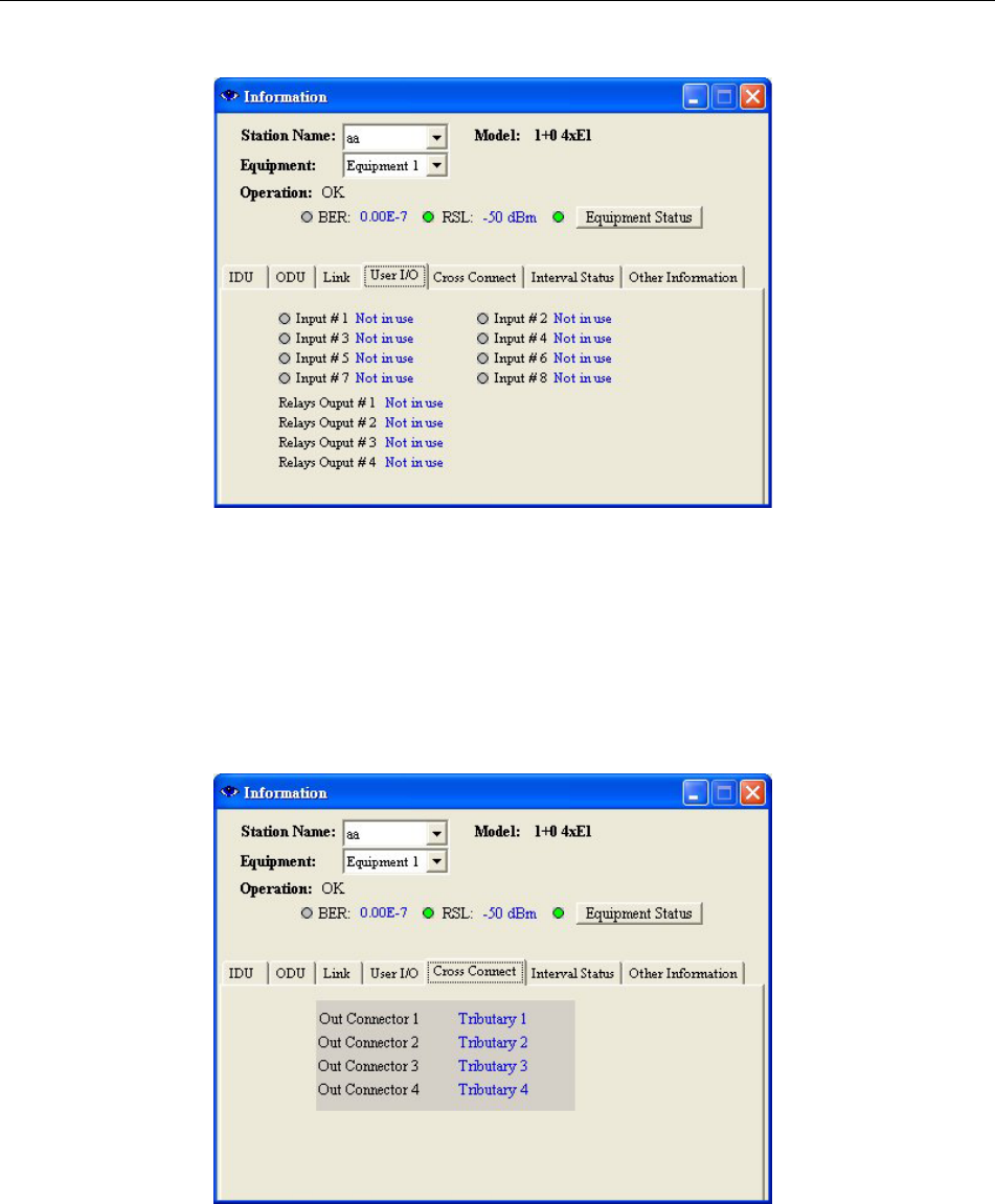
Under Information windows Æ User I/O tab:
E1 Spread Spectrum Radios
8-43
Figure 8-63 User I/O Status
Input #n: input port status.
Relays Output #n: output port status.
Under Information windows Æ Cross Connect tab:
Figure 8-64 Cross Connect Status
Out Connector n – Tributary n: cross connection status.
Under Information windows Æ Interval Status tab:
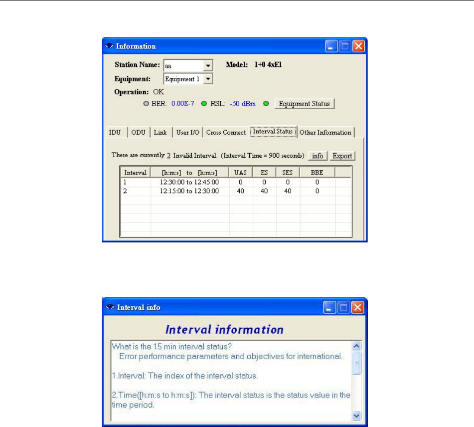
E1 Spread Spectrum Radios
8-44
Figure 8-65 Interval Status
Press the Info tab under Interval Status. The following window appears:
Figure 8-66 Interval Info
Under Information windows Æ Other Information tab:
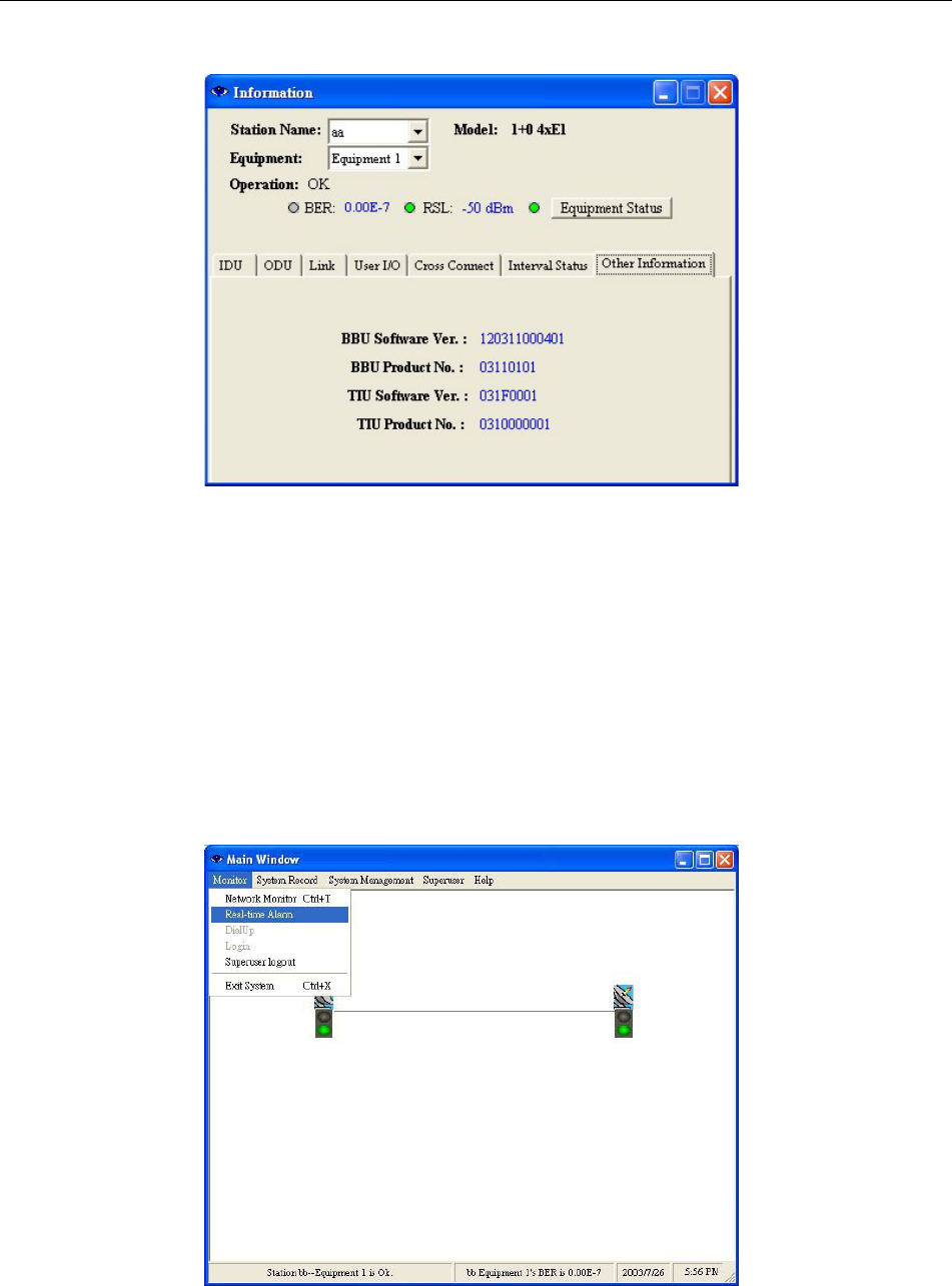
E1 Spread Spectrum Radios
8-45
Figure 8-67 Other Information
BBU Software Ver.: Base Band Unit software version.
BBU Product No.: Base Band Unit product number.
TIU Software Ver.: Traffic Interface Unit software version.
TIU Product No.: Traffic Interface Unit product number.
8.10.2 Real-time Alarm
In the Main Window, select Monitor ÆReal-time Alarm.
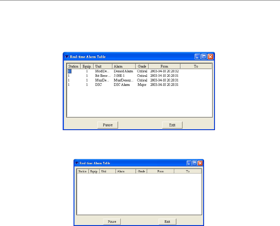
E1 Spread Spectrum Radios
8-46
Figure 8-68: Real-time Alarm (1)
Until and unless the problem is removed or if the whole system is switched off, the real-time alarm will still be
displayed on the window.
Figure 8-69: Real-time Alarm (2)
Pause: To put a pause to all the alarm status without changing, press Pause.
Figure 8-70: No Real-time Alarm
8.10.3 Dial-up
In the remote station, connect the modem to the phone PSTN line. The modem must be also connected to IDU’s
NMS2.
In the local station, login Arbeit. In the Main Window, select Monitor Æ DialUp.
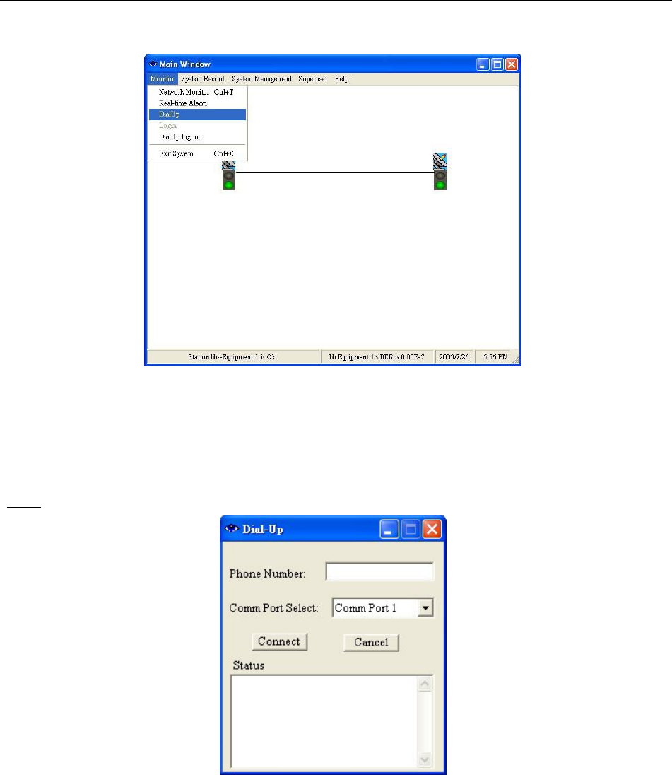
E1 Spread Spectrum Radios
8-47
Figure 8-71 DialUp (1)
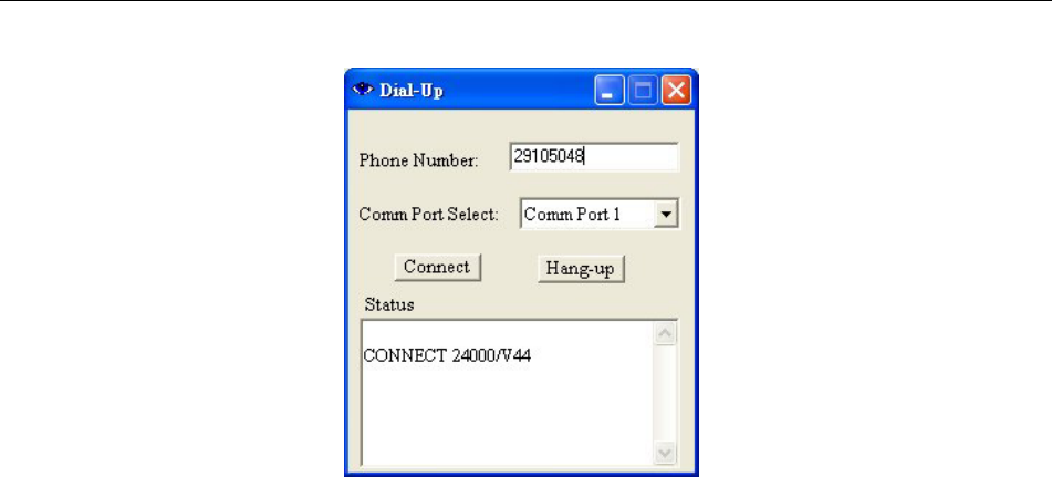
Login DialUp with present account “dialup” and password “dialup”. The following Dial-up windows will appear.
Enter phone number of remote phone. Press Connect. The status appears as shown “CONNECT 24000/V44”. This
means successful connection. Now you may monitor the remote equipment’s status.
ϡNote: This function allows monitoring the status. It does not allow any edit/modify changes.
Figure 8-72 DialUp (2)
E1 Spread Spectrum Radios
8-48
Figure 8-73 DialUp (3)
E1 Spread Spectrum Radios
9-1
9 Appendices
9.1 Specifications
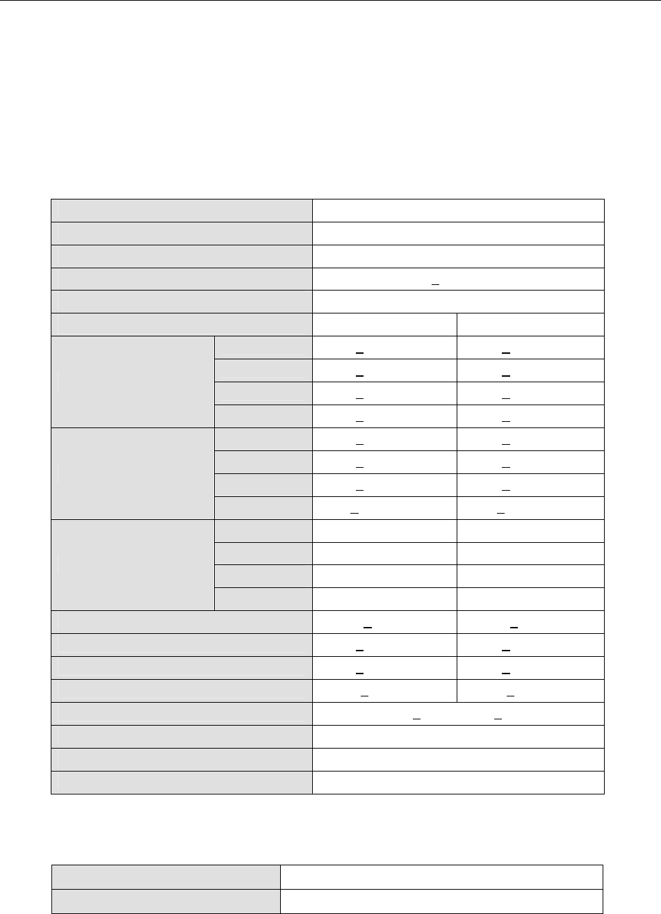
Table 9-1 Transmitter& Receiver
Operation Frequency 2400~2483.5/5725~5850MHz
Communication Mode Frequency Division Duplex, FDD
Modulation QPSK
TX Output Power < 22dBm
RX Dynamic Range -84dBm ~ -15dBm
2.4GHz 5.8GHz
2E1 < -89dBm < -89dBm
4E1 < -86dBm < -86dBm
8E1 < -83dBm < -83dBm
Sensitivity (10-3 BER)
16E1 < -80dBm < -80dBm
2E1 < -87dBm < -87dBm
4E1 < -84dBm < -84dBm
8E1 < -81dBm < -81dBm
Sensitivity (10-6 BER)
16E1 < -77.5dBm < -77.5dBm
2E1 4 Channel 8 Channel
4E1 2 Channel 4 Channel
8E1 1 Channel 2 Channel
Frequency Selection
16E1 1 Channel 1 Channel
BER During Normal Propagation < 10 -10 < 10 -10
Receiver Max Input < -10dBm < -10dBm
Receiver Max Input with no BER < -15dBm < -15dBm
Frequency Stability +10ppm +10ppm
Gain Flatness (anywhere) RX: + 1 dB TX: + 1dB
TX & RX Isolation 60dB
TVS > 40 kilovolts
RSSI (BNC) for Antenna Alignment
Table 9-2 Digital Line Interface
Data Rate 2,048 Mbps
E1 Connector (ITU-T G.703) BNC Unbalanced, 75 ohm

E1 Spread Spectrum Radios
9-2
or
RJ-48, 120 ohm
Signal BER LCD Display on IDU
Table 9-3 IDU Structure
IDU LCD Display of IDU, ODU, Remote, Alarm, Test Item
Information
Alarm Buzzer, LED Indication, LCD Display
FINE IDU Status
ALM Alarm Condition
TEST Test Condition
LED Indication
RMT Remote Status
Table 9-4 Temperature and Environment
Operating Temperature Range IDU:-5 to 55 к
ODU:-30 to 60 к
Humidity IDU:10%~95% Non-condensing
ODU:0%~100%
Altitude 5,000 meters (maximum)
Table 9-5 Network Management System
Operating Method HyperTerminal/Telnet
Interface 10/100BaseT
Protocol Exclusive Arbeit NMS
Table 9-6 IF Cable
Link Cable < 100M RG-6
< 200M RG-8
Frequency 70MHz
Stability 50ppm
Power -35dBm~-5dBm
IDU INPUT
Return Loss VSWR 1.3Љ
IDU OUTPUT Frequency 310MHz

E1 Spread Spectrum Radios
9-3
Stability 50ppm
Power -4dBm±2dBm
Return Loss VSWR 1.3Љ
Frequency 11.0592MHz
Stability 50ppm
Power 150~180mVpp
Monitoring Signal
Return Loss VSWR 1.3Љ
Table 9-7 Power
DC Input -48VDC (-36~ -72V)
Power Consumption < 45 watts
AC Input (optional) 100-240VAC 50-60Hz
Connector Barrier strip, plug-in type
Table 9-8 Service Channel
Frequency 300-3400Hz
Impedance 600 ohm balance
Telephone
Interface RJ-11
Bit Rate 9600 baudЉ
Protocol RS-232
Monitoring Data
(NMS1)
Interface DB-9(Female)
Bit Rate 9600 baudЉ
Protocol RS-232
Monitoring Data
(NMS2)
Interface DB-9(Male)
Bit Rate 9600 baudЉ
Protocol RS-232
Computer Data
(AUX1)
Interface DB-9(Female)
Bit Rate Љ9600 baud
Protocol RS-232
Computer Data
(AUX2)
Interface DB-25(Female)
Type Photo-coupled (TTL)
Interface DB-26(Female)
Number 8
Isolation 3000 VAC(rms)
User Input
LED Power Dissipation 90 mW

E1 Spread Spectrum Radios
9-4
Type Relay output
Interface DB-26(Female)
Number 4
Max. switching voltage 125VAC / 60VDC
User Output
Max. switching current 1A

E1 Spread Spectrum Radios
9-5
9.2 LCD Alarm Items
Table 9-9 LCD Alarm Items
Alarm Grade Status Explanation
MOD Critical Modulation alarm Modulation malfunctions
DEMOD Critical Demodulation lock failure Demodulation signal loss
EOW Major No service between equipments Incorrect connection data
ODU-POW Critical The -48V power supply of IDU malfunctions The cable between IDU & ODU is
short
Link ID Major LINK ID at the remote end is different from
the user’s setting
MUX Critical Receiving lock failure Even bridging cannot lock the timing
I n-LOS Warning IDU cannot detect the input tributary signal No Traffic input parameters
I n- AIS Warning Tributary signal input are all 1’s Traffic input parameters are all 1’s
ODU- M/C Major IDU cannot monitor ODU M&C channel between IDU and
ODU is down
RSL Major Receive signal level alarm Rx connection is not on the best
situation
BER Major Bit error rate alarm Connection is not on the best
situation
-5V Critical ODU -5V power alarm
SSPA Major Solid state power amplifier is off
TX-POW Major Tx is out of range Transmitter is abnormal
PLL-TX Critical Tx of ODU phase lock LO lose lock
PLL-RX Critical Rx of ODU phase lock LO lose lock
PA-I Critical The current is out of range SSPA is abnormal

E1 Spread Spectrum Radios
9-6
9.3 LCD Function
Table 9-10 LCD Function
Status LCD Display Function Description
1 Local ID: n Display the local address Display the local equipment address
2 EOW No.: n Display the service number Display the local equipment’s service phone
number
3 IDU Type: nXE1 Display the activity measure Display the number of E1 equipments
4 Code: AMI/HDB3 Display or set the model
number
Display or set the E1 equipments model
number
5 AUX1: RS-232/RS-422 Display or set the protocol Display the selected protocol
6 AUX2: ASY-CH/SYN-CH Display or set the transmission
methodology Display the transmission method
7 I-Temp: nк IDU working temperature IDU working temperature
IDU
Info
(A)
8 Buzzer: On/Off Buzzer switch Buzzer switch
1 RF-CH Display RF channel Display the present ODU RF channel
2 TxL-SET: n dBm Display the transmit power Display the transmit power, n =
10~22dBm
3 SSPA: On/Off Set the PA to ON/OFF Set the PA to ON/OFF
4 O-Temp: nк ODU working temperature ODU working temperature
5 ATPC: On/Off ATPC switch Increase power when RSL level drops
ODU
Info
(B)
6 RSLtrig: n dBm RSL threshold RSL set to switch on ATPC standard
1Tri-Loc-Loop Tn-L-Lp:
En/Dis Set Local Loopback
Perform loopback test in the local end for
the convenience of testing the local end
equipment’s stability
2Tri-Rem-Loop Tn-R-Lp:
En/Dis Set Remote Loopback
Perform loopback test in the remote end for
the convenience of testing the link system
stability
3Tri-TX-PRBS Tn-PRBS:
En/Dis BER test Use Pseudo Random Code to test the E1
signal transmission
4 Ber-Clear: Clear all accumulated Ber Clear all accumulated Ber on starting the
Ber test
Test
Item
(C)
5 Count-Add: Display all accumulated BER Display all currently accumulated BER on
starting the Ber test

E1 Spread Spectrum Radios
9-7
6 IF-Loop: En/Dis Set IF Loopback
Perform loopback test from IF interface for
the convenience of testing the IDU’s
stability
7 RF-Loop: En/Dis Set RF Loopback
Perform loopback test from RF interface for
the convenience of testing the IDU’s
stability
8 Close-Test: Y/N Close all test Y: close N: cancel
1 Remote ID: n Display the remote address Display the address of the remote
equipment; n=1~255
2 R-Status: OK/Loss Display the system current
working status
Test: remote end in test mode Normal:
normal working condition
3 Far-end OK/Loss Display the connection status
of remote end
OK: in connection
Loss: remote monitor function lost
Remote
Info
(D)
4R-AUX2:
ASY-CH/SYN-CH Display remote AUX2 status Display remote AUX2 status
1MODEM: On/Off Display remote dialup modem
status
Display if any remote dialup modem is
connected or not
2SYS-Conf: 1+ 0 Display system configuration
standby mode Display if there is any standby support
3TX: Active Display transmitting status Display in Active or Standby mode
4RX: Active Display receiving status Display in Active or Standby mode
5Power: -36 ~ -72V Display input power Display input power
6Date: Year/Month/Day Display current date Display current date
Config
Info(E)
7Time: Hour/Min/Sec Display current time Display current time
E1 Spread Spectrum Radios
9-8
9.4 Spread Spectrum List
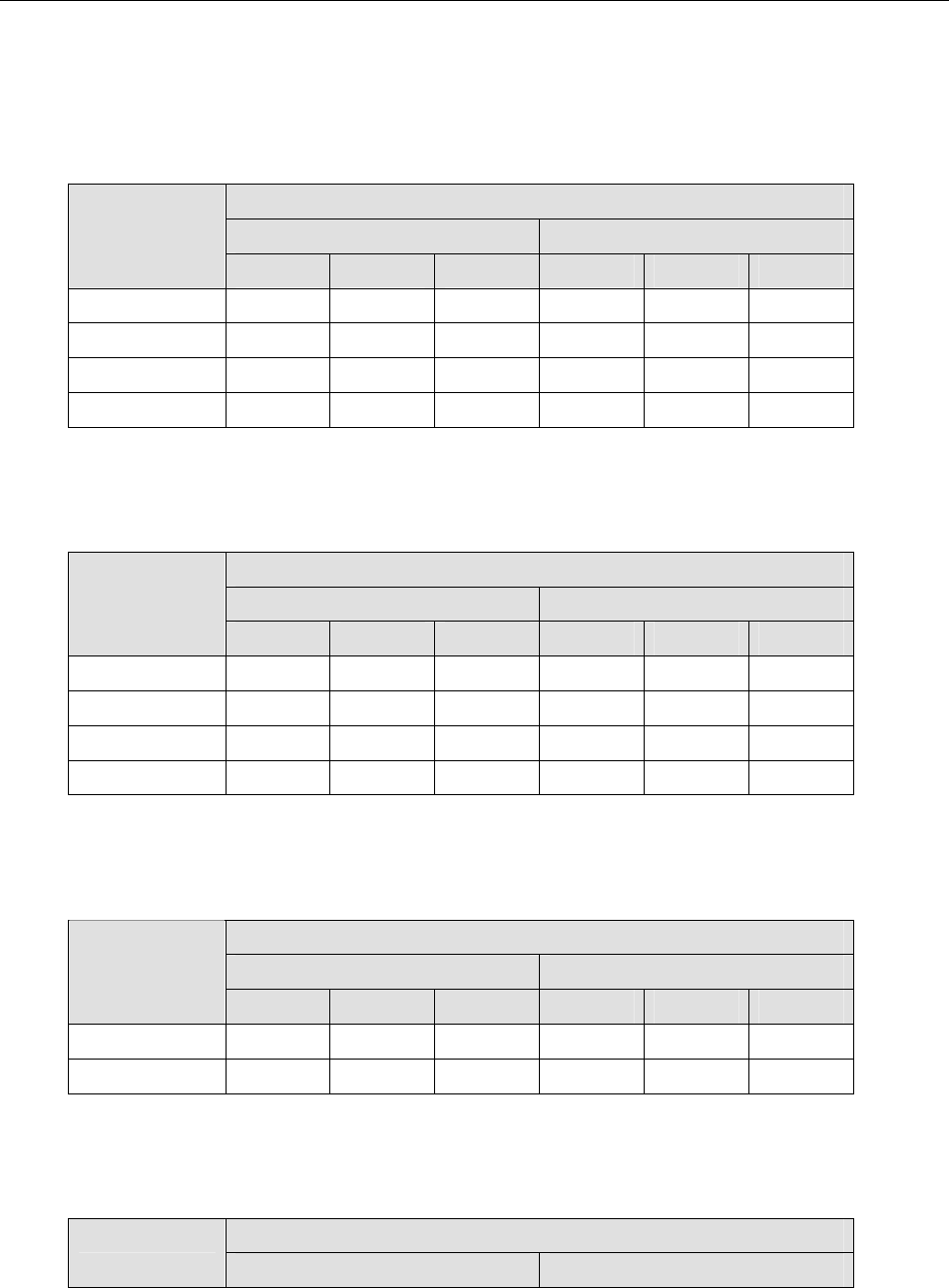
Table 9-11 2.4GHz Spread Spectrum List (2E1, Side A)
2E1
TX RX
Channel
Left Middle Right Left Middle Right
1 2461.5 2465 2468.5 2399.5 2403 2406.5
2 2466.5 2470 2473.5 2404.5 2408 2411.5
3 2471.5 2475 2478.5 2409.5 2413 2416.5
4 2476.5 2480 2483.5 2414.5 2418 2421.5
(Frequency Unit: MHz / QPSK)
Table 9-12 2.4GHz Spread Spectrum List (2E1, Side B)
2E1
TX RX
Channel
Left Middle Right Left Middle Right
1 2399.5 2403 2406.5 2461.5 2465 2468.5
2 2404.5 2408 2411.5 2466.5 2470 2473.5
3 2409.5 2413 2416.5 2471.5 2475 2478.5
4 2414.5 2418 2421.5 2476.5 2480 2483.5
(Frequency Unit: MHz / QPSK)
Table 9-13 2.4GHz Spread Spectrum List (4E1, Side A)
4E1
TX RX
Channel
Left Middle Right Left Middle Right
1 2461 2468 2475 2398 2405 2412
2 2471 2478 2485 2408 2415 2422
(Frequency Unit: MHz / QPSK)
Table 9-14 2.4GHz Spread Spectrum List (4E1, Side B)
4E1Channel
TX RX

E1 Spread Spectrum Radios
9-9
Left Middle Right Left Middle Right
1 2398 2405 2412 2461 2468 2475
2 2408 2415 2422 2471 2478 2485
(Frequency Unit: MHz / QPSK)
Table 9-15 2.4GHz Spread Spectrum List (8E1, Side A)
8E1
TX RX
Channel
Left Middle Right Left Middle Right
1 2460 2474 2488 2396 2410 2424
(Frequency Unit: MHz / QPSK)
Table 9-16 2.4GHz Spread Spectrum List (8E1, Side B)
8E1
TX RX
Channel
Left Middle Right Left Middle Right
1 2396 2410 2424 2460 2474 2488
(Frequency Unit: MHz / QPSK)
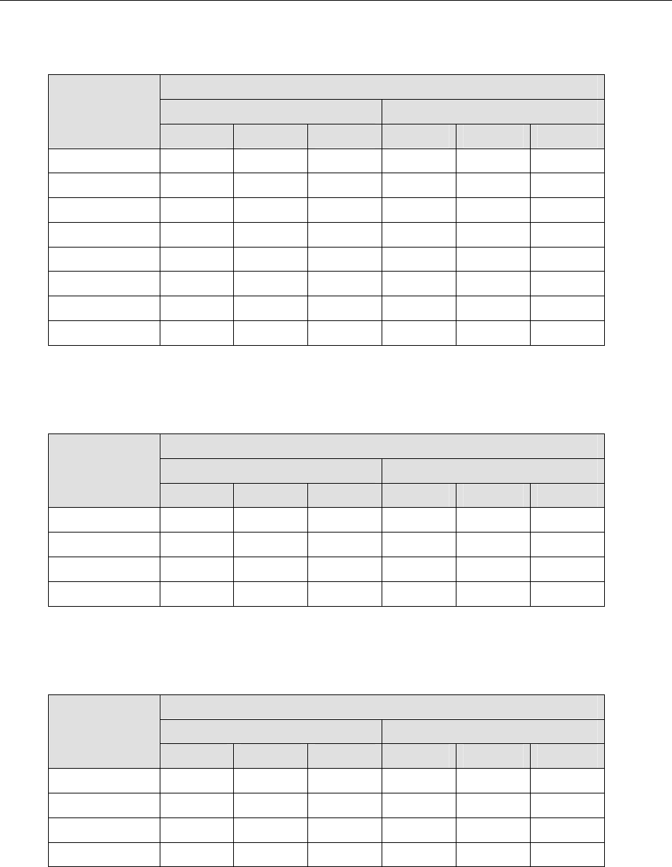
Table 9-17 5.8GHz Spread Spectrum List (2E1, Side A)
2E1
TX RX
Channel
Left Middle Right Left Middle Right
1 5814.25 5816 5817.75 5730.25 5732 5733.75
2 5818.25 5820 5821.75 5734.25 5736 5737.75
3 5822.25 5824 5825.75 5738.25 5740 5741.75
4 5826.25 5828 5829.75 5742.25 5744 5745.75
5 5830.25 5832 5833.75 5746.25 5748 5749.75
6 5834.25 5836 5837.75 5750.25 5752 5753.75
7 5838.25 5840 5841.75 5754.25 5756 5757.75
8 5842.25 5844 5845.75 5758.25 5760 5761.75
(Frequency Unit: MHz / QPSK)
E1 Spread Spectrum Radios
9-10
Table 9-18 5.8GHz Spread Spectrum List (2E1, Side B)
2E1
TX RX
Channel
Left Middle Right Left Middle Right
1 5730.25 5732 5733.75 5814.25 5816 5817.75
2 5734.25 5736 5737.75 5818.25 5820 5821.75
3 5738.25 5740 5741.75 5822.25 5824 5825.75
4 5742.25 5744 5745.75 5826.25 5828 5829.75
5 5746.25 5748 5749.75 5830.25 5832 5833.75
6 5750.25 5752 5753.75 5834.25 5836 5837.75
7 5754.25 5756 5757.75 5838.25 5840 5841.75
8 5758.25 5760 5761.75 5842.25 5844 5845.75
(Frequency Unit: MHz / QPSK)
Table 9-19 5.8GHz Spread Spectrum List (4E1, Side A)
4E1
TX RX
Channel
Left Middle Right Left Middle Right
1 5814.5 5818 5821.5 5730.5 5734 5737.5
2 5822.5 5826 5829.5 5738.5 5742 5745.5
3 5830.5 5834 5837.5 5746.5 5750 5753.5
4 5838.5 5842 5845.5 5754.5 5758 5761.5
(Frequency Unit: MHz / QPSK)
Table 9-20 5.8GHz Spread Spectrum List (4E1, Side B)
4E1
TX RX
Channel
Left Middle Right Left Middle Right
1 5730.5 5734 5737.5 5814.5 5818 5821.5
2 5738.5 5742 5745.5 5822.5 5826 5829.5
3 5746.5 5750 5753.5 5830.5 5834 5837.5
4 5754.5 5758 5761.5 5838.5 5842 5845.5
(Frequency Unit: MHz / QPSK)

E1 Spread Spectrum Radios
9-11
Table 9-21 5.8GHz Spread Spectrum List (8E1, Side A)
8E1
TX RX
Channel
Left Middle Right Left Middle Right
1 5815 5822 5829 5731 5738 5745
2 5831 5838 5845 5747 5754 5761
(Frequency Unit: MHz / QPSK)
Table 9-22 5.8GHz Spread Spectrum List (8E1, Side B)
8E1
TX RX
Channel
Left Middle Right Left Middle Right
1 5731 5738 5745 5815 5822 5829
2 5747 5754 5761 5831 5838 5845
(Frequency Unit: MHz / QPSK)
Table 9-23 5.8GHz Spread Spectrum List (16E1, Side A)
16E1
TX RX
Channel
Left Middle Right Left Middle Right
1 5816 5830 5844 5732 5746 5760
(Frequency Unit: MHz / QPSK)
Table 9-24 5.8GHz Spread Spectrum List (16E1, Side B)
16E1
TX RX
Channel
Left Middle Right Left Middle Right
1 5732 5746 5760 5816 5830 5844
(Frequency Unit: MHz / QPSK)
E1 Spread Spectrum Radios
9-12
9.5 ODU IF & RF Status
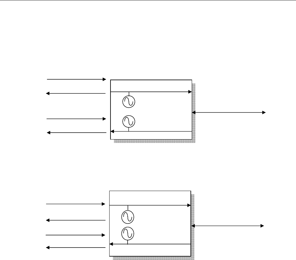
9.5.1 2.4GHz Status
Figure 9-1 Side A IF & RF Status
Figure 9-2 Side B IF & RF Status
ODU Side B: RF Unit
Tx: 2.40~2.42GHz
Tx: 2.463~2.483GHz
ODU Side A: RF Unit
Rx: 2.40~2.42GHz
Rx: 2.463~2.483GHz
IF 310MHz
IF 70M
-48V/ 0.5A
Monitor 11.0592MHz
IF 310MHz
IF 70M
-48V/ 0.5A
Monitor 11.0592MHz
E1 Spread Spectrum Radios
9-13
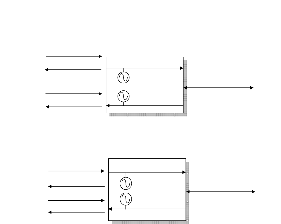
9.5.2 5.8GHz Status
Figure 9-3 Side A IF & RF Status
Figure 9-4 Side B IF & RF Status
Tx: 5.814~5.846GHz
ODU Side A: RF Unit
Rx: 5.730~5762GHz
IF 310MHz
IF 70M
-48V/ 0.5A
Monitor 11.0592MHz
ODU Side B: RF Unit
Tx: 5.730~5.762GHz
Rx: 5.814~5.846GHz
IF 310MHz
IF 70M
-48V/ 0.5A
Monitor 11.0592MHz

E1 Spread Spectrum Radios
9-14
9.6 The Definition of Pins
Table 9-25 DB9 female pins of NMS1
DB-9 Description
1
2 Transmitted data ΰOUTPUTα
3 Received data (INPUT)
4
5 GND
6
7 Request to send (INPUT)
8
9 NC
Table 9-26 DB9 male pins of NMS2
DB-9 Description
1 Received Line Signal Detector (INPUT)
2 Receive data (INPUT)
3 Transmit data (OUTPUT)
4
5 GND
6 DCE Ready (INPUT)
7
8
9 NC
Table 9-27 DB9 female pins of AUX1 (V.28)
DB-9 Description
1 NC
2 TXD (OUTPUT)
3 RXD ΰINPUTα
4
5 GND
6
7
8
9
Table 9-28 DB9 female pins of AUX1 (V.11)

E1 Spread Spectrum Radios
9-15
DB-9 Description
1 NC
2 TXD- (OUTPUT)
3 RXD+ (INPUT)
4
5 GND
6
7 TXD+ (OUTPUT)
8 RXD- (INPUT)
9
Table 9-29 DB26 pins of USER I/O
DB-26 Description
1 Input 3
2 GND
3 Input 4
4 Output 1C
5 Output 1NC
6 Output 1NO
7 Output 3C
8 Output 3NC
9 Output 3NO
10 Input 2
11 Input 5K
12 Input 5A
13 Input 6K
14 Input 6A
15 Input 7K
16 Input 7A
17 Input 8K
18 Input 8A
19 GND
20 Input 1
21 Output 4NO
22 Output 4NC
23 Output 4C
24 Output 2NO
25 Output 2NC
26 Output 2C
Table 9-30 DB25 pins of AUX2
DB-25 Description
1 GND

E1 Spread Spectrum Radios
9-16
2 TX+ ΰOUTPUTαtransmit data+
3 RX+ (INPUT) receive data+
4
5
6
7 GND
8
9 RC- (OUTPUT) receive clock-
10
11
12 TC- (OUTPUT) transmit clock-
13
14 TX- (OUTPUT) transmit data-
15 TC+ (OUTPUT) transmit clock
16 RX- (INPUT) receive data-
17 RC+ (OUTPUT) receive clock+
18
19
20
21
22
23
24
25

E1 Spread Spectrum Radios
9-17
9.7 Installation Guide
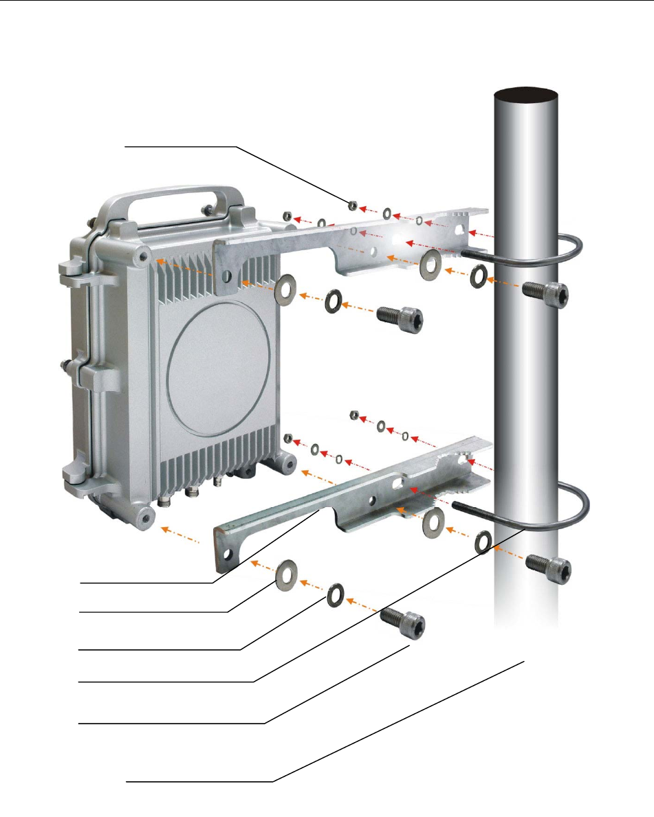
9.7.1 Parts of ODU assembly
Nut[1] Split Washer[2] Flat Washer[3] Hex Screw[4]
ODU Fastening Assembly
Figure 9-5 Part accessories
Part Q’TY
Nut[1] 4
Split Washer[2] 8
Flat Washer[3] 8
Hex Screw[4] 4
Mounting Bracket[5] 2
U-Bracket[6] 2
Mounting Bracket [5]
U-Bracket[6]
E1 Spread Spectrum Radios
9-18
9.7.2 ODU Installation Diagram
Figure 9-6 ODU Installation Diagram
1
2
3
4
5
6
ODU Mast
E1 Spread Spectrum Radios
9-19
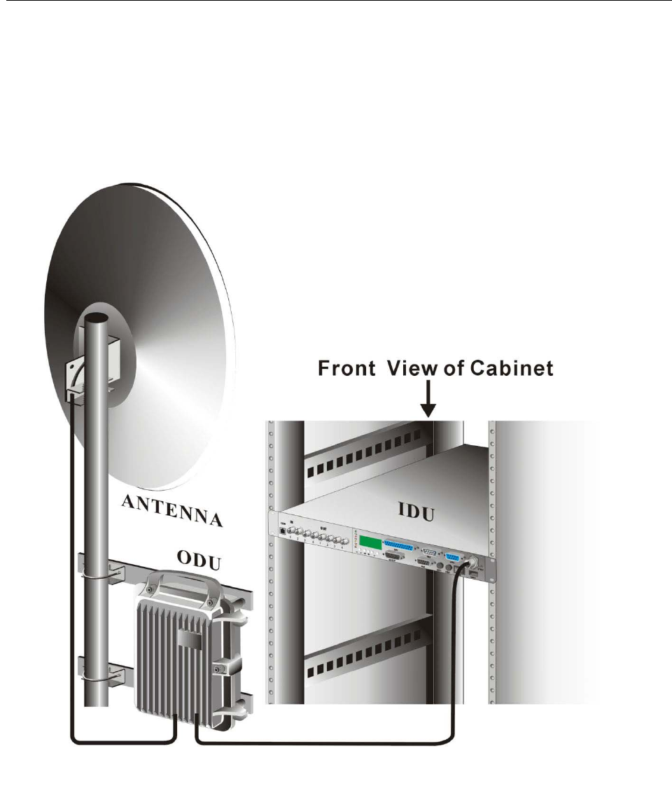
9.7.3 IDU+ODU Quick Installation
For RJ-48/BNC Type
Figure 9-7 IDU & ODU Connection Diagram
E1 Spread Spectrum Radios
9-20
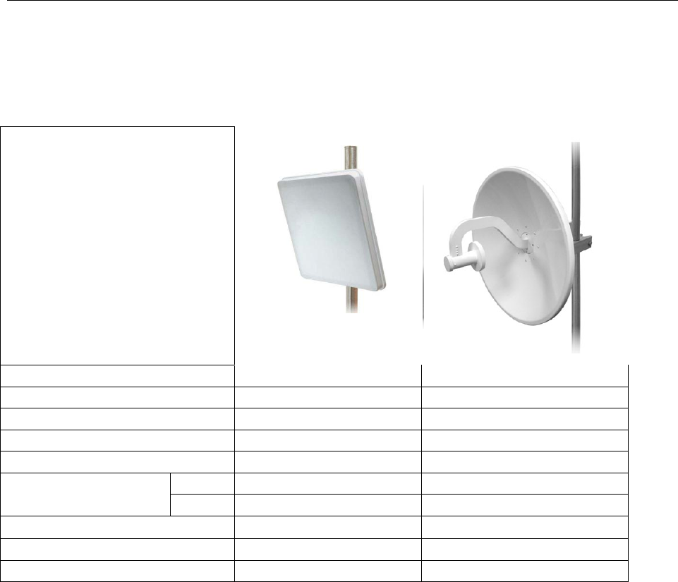
9.7.4 Antenna Installation
Prerequisite: We have passed FCC certification of our system with following antennas. We strongly suggest that you
should use the same antenna to avoid unexpected problems occurred in the operation.
Model Number. KBNT5822-16 KBNT5828-25
Frequency 5725~5875MHz 5725~5875MHz
Gain(dBi) 22 28.5
Type Panel Solid Dish
Polarization Horizontal, vertical Horizontal, vertical
Hor. 6 6
Beamwidth Ver. 6 6
VSWR Љ1.4 Љ1.15
Dimensions(mm) 350*350*37,1.2kg ĭ60cm
Connector N-male N-type
Step1: Mount your antenna and ODU in the appropriate position. The correct position depends on your needs. You
should also take the distance between antenna and ODU into consideration. The distance is larger, then you need a
longer cable to connect which usually stands for higher cable loss.
Step2: Turn off you power of the system.
Step3: Correctly connect your cable between ODU and antenna.
Step4: Turn on the power of the system with SSPA function off. Try to adjust antenna angle by checking the LED
light number or RSSI voltage to achieve the best performance. This step would decrease the power to the minimum
level so that it won’t harm the installer.
Step5: When best performance is achieved, then turn on the SSPA function to make the transmission better to avoid
air interference or weather attenuation. Then the antenna installation is completed.
E1 Spread Spectrum Radios
9-21
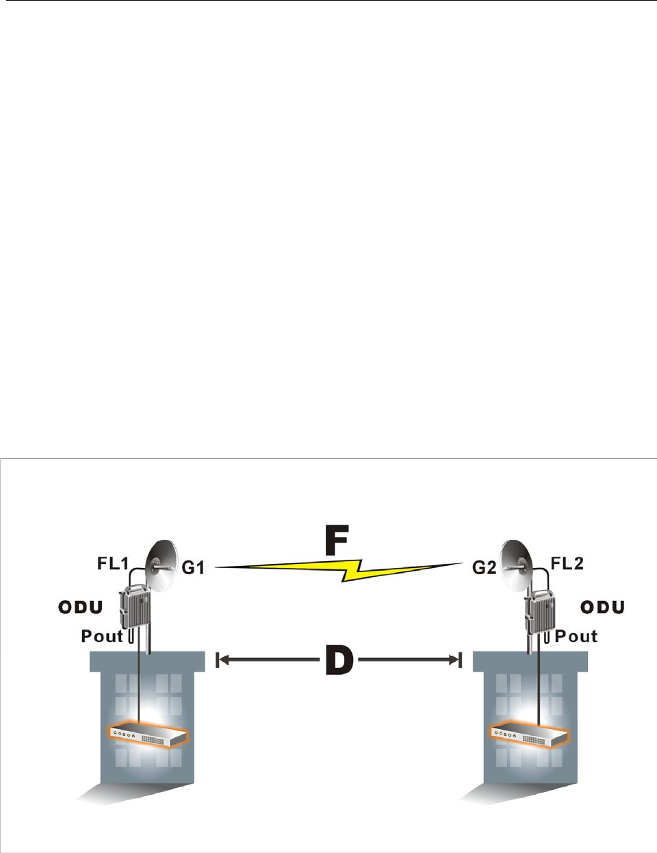
9.8 RSL and Link Budget
The received signal level (RSL) can be estimated using the following formula:
RSL (dBm) = Pout – FL1 + G1 + G2 – FL2 – LP
where: Pout is the transmitter output power (in dBm)
FL1 is the feeder loss of the transmit side (in dBm)
G1 is the gain of the transmit antenna (in dB)
G2 is the gain of the receive antenna (in dB)
FL2 is the feeder loss of the receive side (in dB)
LP is the Path loss, defined by:
LP (dB) = 96.6 + 20 log10F + 20 log10D
where: F = Frequency in GHz (1.5, 2.4 or 5.8)
D = Distance of path in km
This link budget is very important for determining any potential problems during installation. If you have
calculated the expected RSL, you can see if it has been achieved during installation, and troubleshoot if
necessary.
Figure 9-8 RSL and Link Budget