KIMIN Electronics RJP-100M REMOTE JACK PACK User Manual User s Manual H
Kimin Electronic Co., Ltd REMOTE JACK PACK User s Manual H
UserManual.wiki
>
KIMIN Electronics
>
RJP 100M User Manual
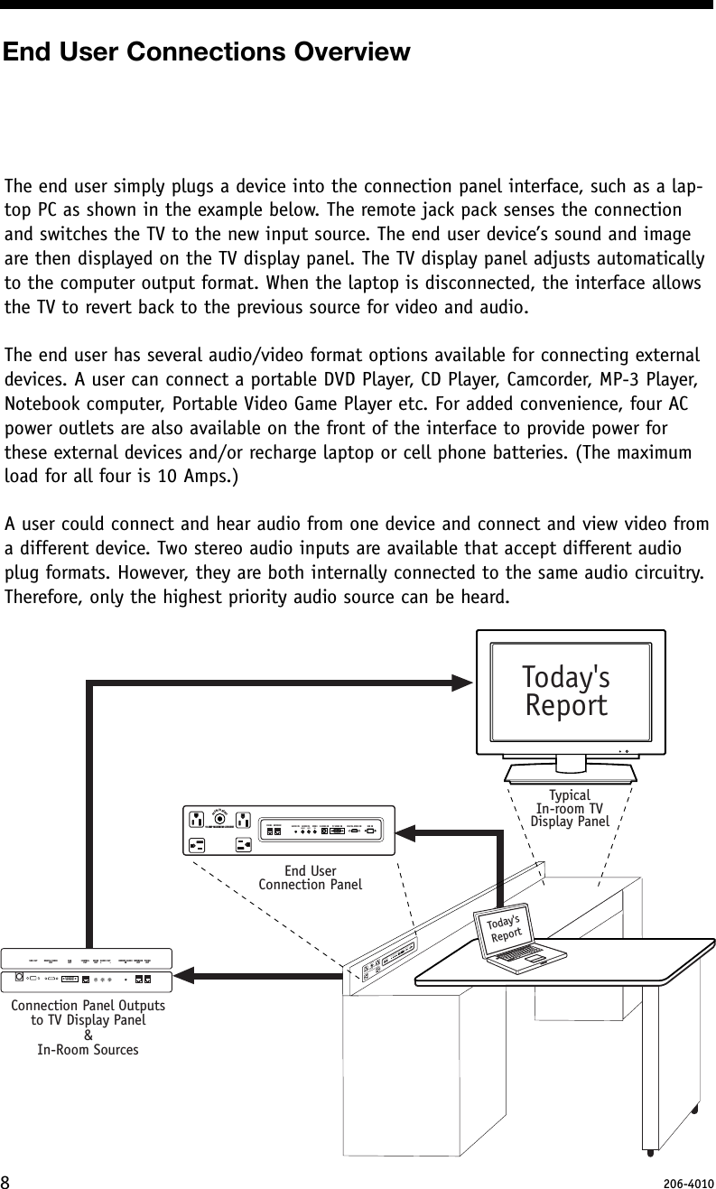
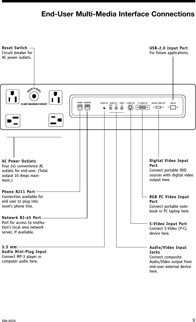
USERS MANUAL
Navigation menu
Upload a User Manual
Namespaces
Wiki Guide
HTML
PDF
Info
Views
User Manual
Discussion / Help
Navigation