KIMIN Electronics RJP-100M REMOTE JACK PACK User Manual User s Manual H
Kimin Electronic Co., Ltd REMOTE JACK PACK User s Manual H
USERS MANUAL

EUT Type: RJP-100M
FCC ID: TGERJP-100M
Test Report No.: GETEC-E3-05-052
FCC Class B Certification
APPENDIX H
: USER’S MANUAL

RJP-100M
Remote Jack Pack
Installation
& Setup Guide
Warranty
© Copyright 2005, LG Electronics U.S.A., Inc.

2
For Customer Support/Service, please call: 1-888-865-3026
www.lgcommercial.com
206-4010
The exclamation point within an equilateral triangle is intended to alert the user to the presence
of important operating and maintenance (servicing) instructions in the literature accompanying the
appliance.
CAUTION:
TO REDUCE THE RISK OF ELECTRIC SHOCK - - USE ONLY INDOORS
ATTENTION:
RISQUE DE CHOCS ÉLECTRIQUE - - POUR INSTALLATION À L¡¯INTÉRIEUR SEULEMENT
WARNING:
TO PREVENT FIRE OR SHOCK HAZARDS, DO NOT EXPOSE THIS PRODUCT TO RAIN OR MOISTURE.
Apparatus shall not be exposed to dripping or splashing and no objects filled with liquids, such as
vases, shall be placed on the apparatus.
L’appareil ne doit pas être exposé à des égouttements d’eau ou des éclaboussures et de
plus qu’aucun objet rempli de liquide tel que des vases ne doit être placé sur l’appareil.
REGULATORY INFORMATION:
This equipment has been tested and found to comply with the limits for a Class B digital device, pur-
suant to Part 15 of the FCC Rules. These limits are designed to provide reasonable protection against
harmful interference when the equipment is operated in a residential installation. This equipment gen-
erates, uses and can radiate radio frequency energy and, if not installed and used in accordance with
the instruction manual, may cause harmful interference to radio communications. However, there is no
guarantee that interference will not occur in a particular installation. If this equipment does cause
harmful interference to radio or television reception, which can be determined by turning the equip-
ment off and on, the user is encouraged to try to correct the interference by one or more of the fol-
lowing measures:
• Reorient or relocate the receiving antenna.
• Increase the separation between the equipment and receiver.
• Connect the equipment into an outlet on a circuit different from that to which the receiver
is connected.
• Consult the dealer or an experienced radio/TV technician for help.
CAUTION:
Do not attempt to modify this product in any way (except as noted herein) without written authoriza-
tion from LG Electronics U.S.A., Inc. Unauthorized modification could void the user’s authority to
operate this product.
COMPLIANCE:
The responsible party for this product’s compliance is:
LG Electronics U.S.A., Inc., 2000 Millbrook Drive
Lincolnshire, IL 60069, USA • Phone: 1-847-941-8000.
©Copyright 2005, LG Electronics U.S.A., Inc.
Note: Design and specifications are subject to change without prior notice.
Marketed and Distributed in the United States by LG Electronics U.S.A., Inc.
2000 Millbrook Drive, Lincolnshire, IL 60069
PHONE NETWORK AUDIO IN AUDIO IN VIDEO IN S-VIDEO IN PC VIDEO IN DIGITAL VIDEO IN USB IN
LR
10 AMP MAXIMUM CURRENT
P
R
E
S
T
O
S
R
E
S
E
T
Overview
The Remote Jack Pack (RJP) contains circuitry to determine the
presence of a signal at each input jack.
(Note: The initial implementation only monitors the right audio
input of each audio source.)
When a signal is detected, it’s priority is compared to the priori-
ty of other sources which may be present. Control signals from
the RJP to the display panel change state, if the new active
source is of higher priority than the existing source, to direct the
display panel to proper source.
Video and audio are monitored and switched independently.
Power is supplied to the RJP by the display panel via the control
signal cable.
3
206-4010

206-4010
Introduction
Conveniently installed right in the room where guests will stay, the LG Remote
Jack Pack, multi-media interface is available to end users to connect audio,
video and computer devices to hear and view on the in-room TV display panel.
The RJP-100M can be set up to interface with the TV display panel to show
the image and/or sound from a portable DVD/CD Player, Camcorder, MP-3
Player, Notebook computer, or portable Video Game Player. Or, devices with
digital video outputs such as DVD players. A USB-2.0 connection is available
for future applications. If the end user does not connect any devices, then
the in-room TV display panel will remain on the source selected. When the
end user connects a device, the interface switches the TV display panel to the
new source. Satellite radio may be available at some locations. Users can
charge laptops or cell phones while watching TV.
The RJP-100M interface is designed to be able to process audio from one
source, and video separately from a different source, if required. (A user can
do work on a laptop PC and hear music from an MP-3 player.) However, only
one audio and one video source can be heard/seen at the same time.
The user simply plugs the device’s power cord into one of the four conve-
nience AC power outlets provided on the RJP-100M. Turns the device on and
the RJP-100M switches to the newly-connected audio and/or video source. No
end user menus are involved, connections are made directly to the interface.
The RJP-100M continually monitors the signal of the source inputs. When a
signal is detected, (a device is plugged into one of the source inputs) the
interface sends a message to the TV display panel which then switches to the
newly-connected source. The interface sends the audio and video so that it
can be heard and seen on the TV display panel. 12-Volt DC power is supplied
from the TV display panel to operate the interface via the control cable.
Overview (Contd.)
CLEANING CAUTION:
Since the end user jackpack is exposed, use extreme caution when
cleaning. Do not use liquid cleaners on the connections panel. Do
not allow liquids to be spilled, sprayed onto or otherwise come into
contact with the connections panel on both the end user side and
the installer side. Clean with a slightly damp cloth.
10 AMPS MAXIMUM TO ALL FOUR AC OUTLETS:
The maximum combined total current that is allowable to the 4 AC
power outlets is 10 Amps. These are protected by a circuit breaker
type re-setable fuse.
4
AUDIO OUT
VIDEO
OUT
REMOTE AUDIO
IN PHONE
OUT
NETWORK
OUT
R L
RGB
OUT
DIGITAL VIDEO
OUT CONTROL
OUT
USB OUT
.....
.....
5
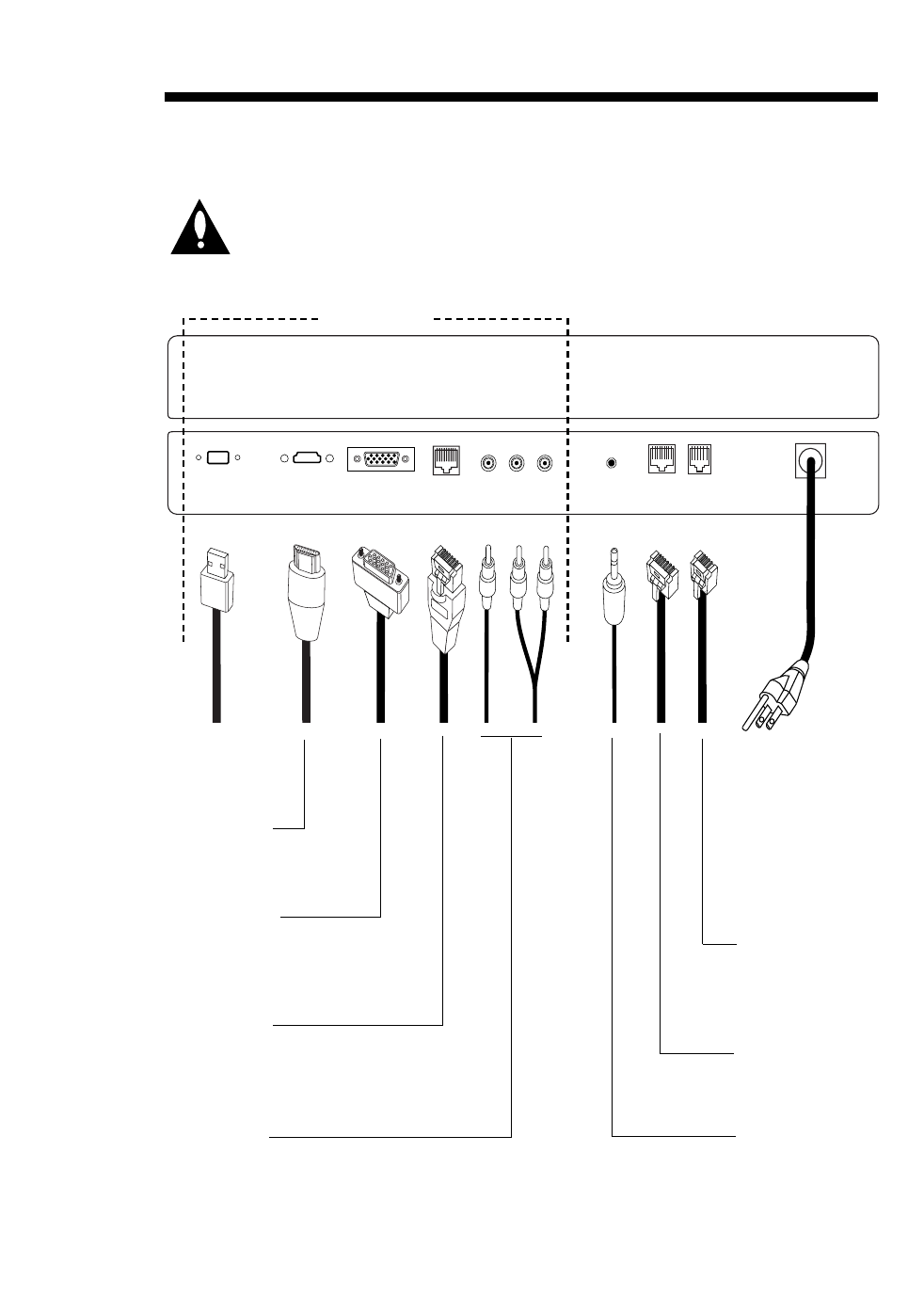
CAUTION: Be sure power is turned off before attempting to connect remote
jack pack to the TV display panel and in-room resources.
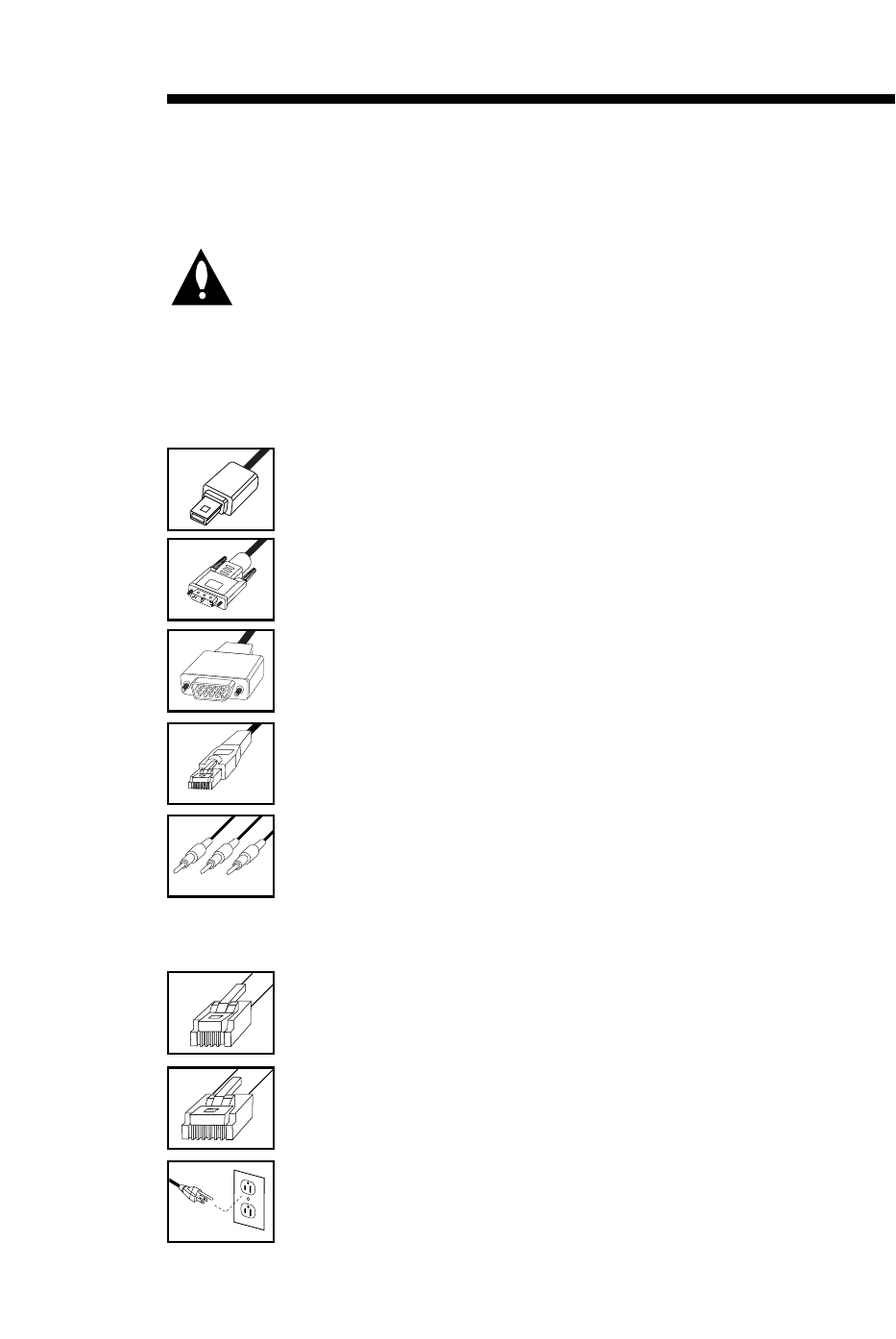
8-Pin RJ45
Network Cable
LAN server input.
6-Pin RJ11
Phone Cable
Connect to tele-
phone line wall jack
panel.
Remote Satellite
Radio 3.5 mm
Mini-Plug Cable
Connect to satellite
radio and other
remote audio prod-
ucts.
206-4010
Installer Connections
AC Power Cord
Connect to 120V 60
Hz AC power outlet.
Supplies power to
the four convenience
AC power outlets for
end user. (Maximum
total output to all 4
outlets is 10 Amps.)
Control 8-Pin
RJ45 Cable w/Yellow Sleeve
Connect to RJP input
port on TV display
panel.
Audio/Video
Cables
Connect composite
Audio/Video out-
puts to TV display
panel.
RGB Computer
Cable
Connect to TV dis-
play panel RGB
input.
Digital Video
Cable
Connect to TV
display panel.
USB Cable
For future
applications.
Cable Assembly

6
System Installation
Connect the multi-media interface to the TV display panel and other control devices (if
applicable) using the output ports and jacks available on the back panel. A brief
description of each connection available is provided below.
USB Output Port
For future applications--e.g., digital cameras and flash drives.
Digital Video Output
Connect to digital video input port on TV display panel to allow user to show DVD’s
high-resolution digital video on the in-room TV.
Computer RGB Output
Connect to RGB input port on TV display panel to allow user to show a PC/Laptop
image on the in-room TV.
Control 8-Pin RJ-45 Output Port
Data link. Connection to TV display panel for control and power supply for interface.
Audio/Video Output Jacks
Connect to composite R-Audio-L / Video input on TV display panel.
Audio Mini Plug Input
Input connection for remote satellite radio source. Connect to satellite radio or any
other remote audio source as needed.
8-Pin RJ-45 Output Port
Output port to allow access to local area network server if available. Allows the end
user to access the LAN (local area network) of the institution.
6-Pin RJ-11 Output Port
Output port available for connection to telephone line wall jack panel. Using a com-
puter modem, allows the end user to access the Internet through a local phone line.
AC Power Cord
Connect to standard 120V 60Hz AC power outlet.
(Four 120 Volt 60 Hz AC power outlets are provided for the end user. However,
10 Amps. is the maximum output to all four AC power outlets.)
206-4010
7
System Installation: Cables Required for RJP-100M
The following cables are included in the cable assembly bundle
USB 2.0 Cable
Typical “Mini-B” male, connect to USB host.
Digital Video Cable
Connect to high definition digital video input on TV display panel.
RGB Computer Cable
15-pin standard PC computer cable of sufficient length to connect inter-
face to TV display panel.
8-Pin RJ-45 Cable (with Yellow Protective Sleeve)
Connects to RJ-45 control input port on TV display panel. Display panel
supplies DC power to operate RJP-100M.
Audio/Video Cables
1-Set of standard composite R-Audio-L / Video cables to connect to TV
display panel’s composite audio/video input jacks.
The following cables are separate
6-Pin RJ-11 Cable
1 cable of sufficient length for connection to room telephone line wall
jack panel.
8-Pin RJ-45 Cable
1 cable of sufficient length to connect to RJ-45 wall LAN network jack,
if available in hotel.
AC Power Cord
Connect to a standard 120V 60Hz AC power outlet.
. . . . . . . .
. . . . . . . .
. . . . . . . .
In order to use the remote jack pack, the TV display panel and the following
cables will need to be connected to both the RJP-100M and resources avail-
able in room.
206-4010
.....
.....
Note: Connector set near mesh sleeving hooks up
to TV display panel.
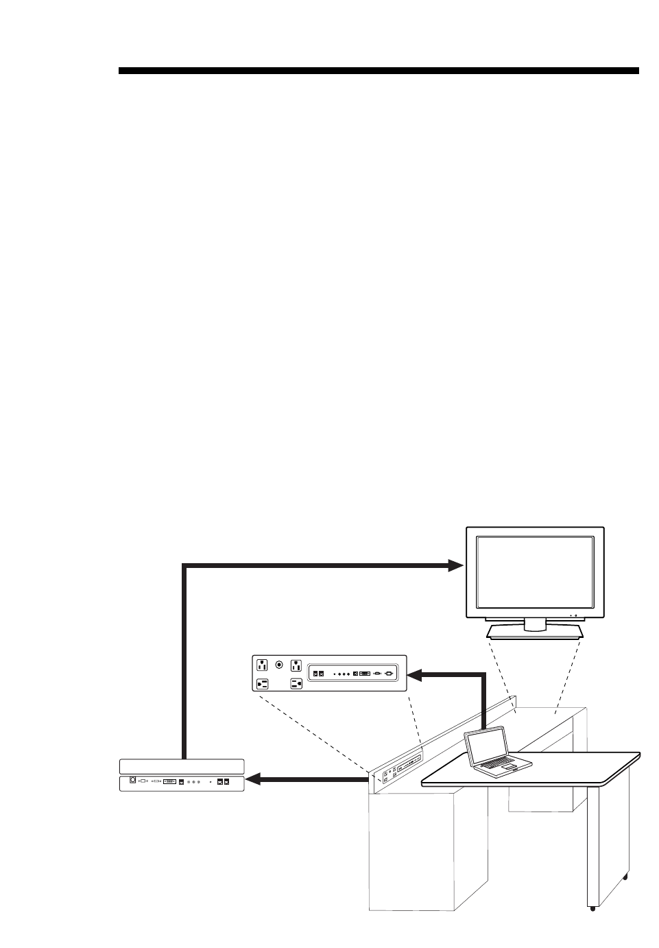
The end user simply plugs a device into the connection panel interface, such as a lap-
top PC as shown in the example below. The remote jack pack senses the connection
and switches the TV to the new input source. The end user device’s sound and image
are then displayed on the TV display panel. The TV display panel adjusts automatically
to the computer output format. When the laptop is disconnected, the interface allows
the TV to revert back to the previous source for video and audio.
The end user has several audio/video format options available for connecting external
devices. A user can connect a portable DVD Player, CD Player, Camcorder, MP-3 Player,
Notebook computer, Portable Video Game Player etc. For added convenience, four AC
power outlets are also available on the front of the interface to provide power for
these external devices and/or recharge laptop or cell phone batteries. (The maximum
load for all four is 10 Amps.)
A user could connect and hear audio from one device and connect and view video from
a different device. Two stereo audio inputs are available that accept different audio
plug formats. However, they are both internally connected to the same audio circuitry.
Therefore, only the highest priority audio source can be heard.
End User Connections Overview
Typical
In-room TV
Display Panel
End User
Connection Panel
Connection Panel Outputs
to TV Display Panel
&
In-Room Sources
®
Today's
Report
Today's
Report
AUDIO OUT
VIDEO
OUT
REMOTE AUDIO
IN PHONE
OUT
NETWORK
OUT
R L
RGB
OUT
DIGITAL VIDEO
OUT CONTROL
OUT
AUDIO IN
VIDEO
IN
AUDIO IN
PHONE NETWORK
RIGHT LEFT
PC VIDEO IN DIGITAL VIDEO IN
S-VIDEO IN
P
R
E
S
T
O
S
R
E
USB IN
10 AMP MAXIMUM CURRENT
S
E
T
AUDIO IN
VIDEO
IN
AUDIO IN
PHONE NETWORK
RIGHTLEFT
PC VIDEO IN DIGITAL VIDEO IN
S-VIDEO IN
P
R
E
S
T
O
S
R
E
USB IN
10 AMP MAXIMUM CURRENT
CAUTION
DO NOT USE WITH HAIR DRYERS, IRONS OR COFFEE POTS
S
E
T
USB OUT
206-4010
8
9
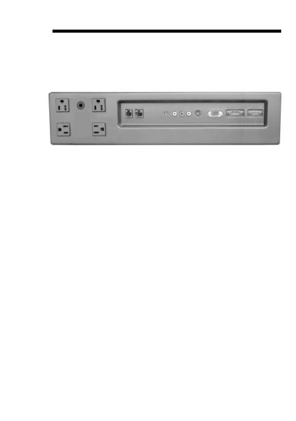
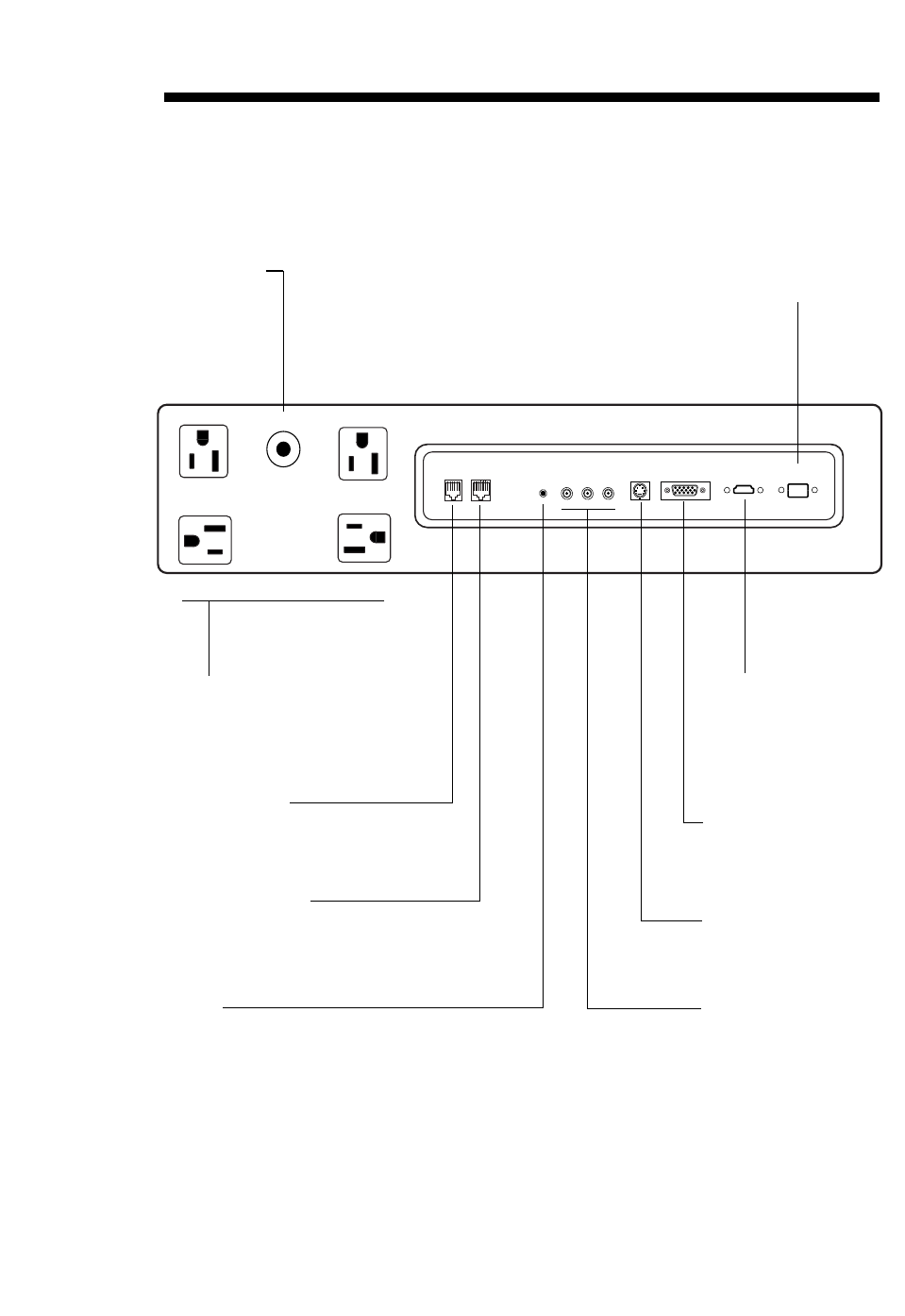
End-User Multi-Media Interface Connections
AUDIO IN
VIDEO
IN
AUDIO IN
PHONE NETWORK
RIGHT LEFT
PC VIDEO IN DIGITAL VIDEO IN
S-VIDEO IN
P
R
E
S
T
O
S
R
E
USB IN
10 AMP MAXIMUM CURRENT
S
E
T
Reset Switch
Circuit breaker for
AC power outlets.
AC Power Outlets
Four (4) convenience AC
outlets for end-user. (Total
output 10 Amps maxi-
mum.)
Phone RJ11 Port
Connection available for
end user to plug into
room’s phone line.
Network RJ-45 Port
Port for access to institu-
tion’s local area network
server, if available.
Audio/Video Input
Jacks
Connect composite
Audio/Video output from
end-user external device
here.
S-Video Input Port
Connect S-Video (Y-C)
device here.
RGB PC Video Input
Port
Connect portable note-
book or PC laptop here.
3.5 mm
Audio Mini-Plug Input
Connect MP-3 player or
computer audio here.
Digital Video Input
Port
Connect portable DVD
sources with digital video
output here.
206-4010
USB-2.0 Input Port
For future applications.
10
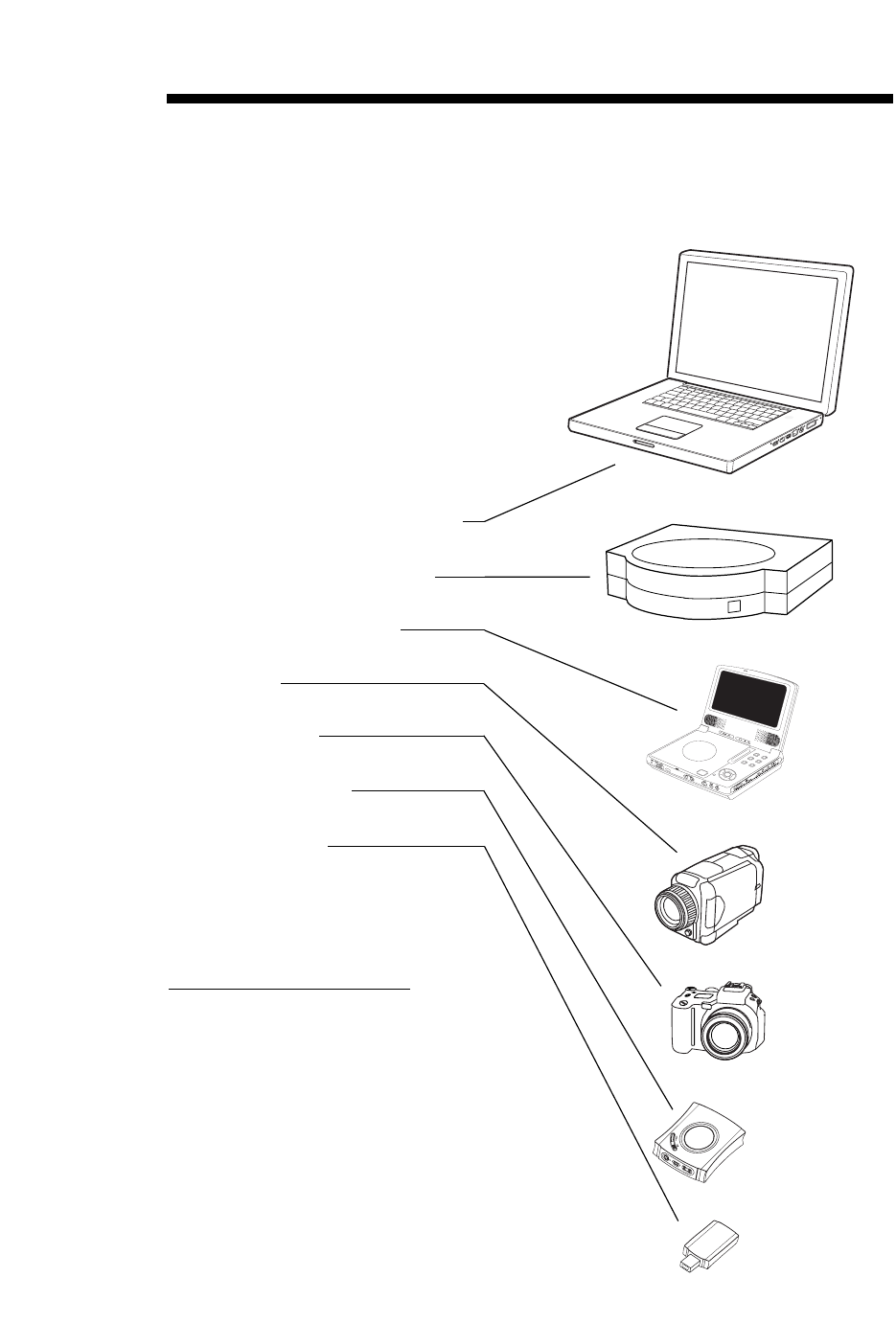
End-User Connectable External Source Devices
Examples of devices a user can
connect are shown to the right.
There are four AC power outlets
available on the jack pack for
added convenience.
The end-user can connect:
PC Laptop/Notebook Computers
Portable Video Game Players
Portable DVD/CD Players
Camcorders
Digital Cameras
MP-3 Audio Players
USB Flash Drives
and other USB devices
Digital Video Compatible
Note: The RJP-100M is digital
video compatible. It is capable of
interfacing with DVD players that
have digital video output.
206-4010
206-4010
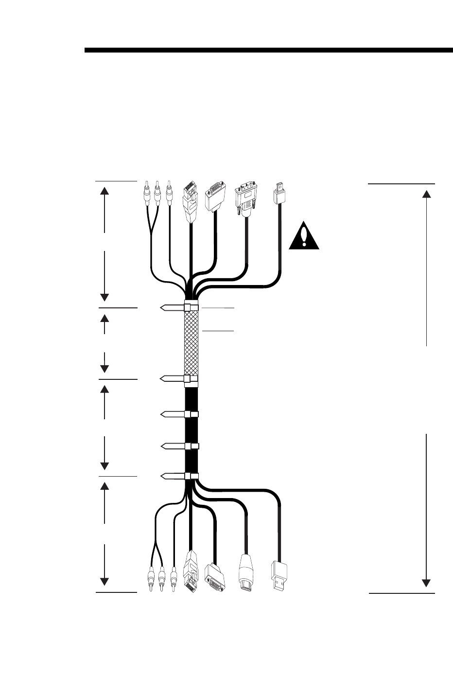
12-Foot Output Cable Assembly
Reference
1.
AUDIO
R-L
2.
VIDEO
4.
RGB 5.
DIGITAL
VIDEO
3.
CONTROL
w/Yellow
Sleeve
6.
USB-2.0
Output
Cable
Assembly
is
12.0
Feet
in
Length
AUDIO
R-L
VIDEO
RGB DIGITAL
VIDEO
CONTROL
w/Yellow
Sleeve
USB-2.0
(For Future Applications)
Output Cable Assembly Parts List
Item Description
No.
1. Composite RCA type Plugs
Audio R-L Cables.
2. Composite RCA type Plugs
Video Cable.
3. RJ-45 Control Out Cable
w/Yellow Protective Sleeves.
4. RGB Cable.
5. Digital Video Cable.
6. USB-2.0 Cable.
7. Cable Ties.
Connect to Outputs on RJP-100M Jackpack
Connect to Inputs on Display Panel
. . . . . . . .
. . . . . . . .
. . . . . . . .
7. Cable Tie
Mesh Sleeving
14"
36"
12"
82"
USB-2.0
"Mini-B" Male
5-Pin
USB-2.0
"A-Style" Male
4-Pin
.....
.....
.....
.....
11
Note: Connector set
near mesh sleeving
hooks up to TV
display panel.

Specifications
Application
Makes available to the hotel’s guests, a multi-media interface to the in-room
TV display panel and media resources. Jacks are provided for external portable
devices such as DVD/CD Players, Laptop Computers, Camcorders, etc.
Dimensions
Height 4.10 Inches
Width 15.00 Inches
Depth 2.1 Inches
End-User Device Inputs
AC Outlets x 4 AC 120V 60Hz (Maximum 10 Amps.
total output for all four AC outlets)
Phone 6-Pin RJ-11 Phone Jack
Network 8-Pin RJ-45 Communications Jack
Audio In 3.5mm Mini Plug
Audio In L-R Left/Right Audio RCA Type Composite Jacks
(Nom In: 250mV RMS @ 22K ohms)
Overload In: 1.6V RMS Max
Video In Video RCA Type Composite Jack
1 Vpp, 75 ohms
S-Video In Y-C Connector
Y=1 Vpp, 75 ohms. C=0.3 Vpp Color Burst, 75 ohms
PC Video In RGB 15-pin VGA Type Computer Connector
Digital Video In Digital Video Connector for digital video devices,
e.g., DVD Players etc.
USB-2.0 In USB Connector - USB-2.0
Environmental Parameters
Operating Temperature 0 to 40 Degrees Celsius
(32 to 104 Degrees Fahrenheit)
Storage Temperature -20 to 85 Degrees Celsius
(-4 to 185 Degrees Fahrenheit)
Cooling Free Air Convection
Humidity 10% to 90% Non-condensing
12 206-4010

Specifications
Outputs to TV Display Panel & In-Room Resources
USB-2.0 Out USB-2.0 Connector
Digital Video Out Digital Video Connector
Digital Video Specs. Ver 1.1, All ATSC Formats
RGB OUT RGB 15-pin VGA Type Computer Connector
Control Out 8-Pin RJ-45 Communications Jack
with Yellow Protective Sleeve
Video Out 1 Vpp into 75 ohms, Composite or Y+C Combined
RCA Type Composite Video Jack
+/- 1 db @ 4.2 MHz
Audio Out R-L Right/Left RCA Composite Audio Jacks
Max: 1.6 V RMS (1 KHz) @ 600 ohms,
Typ: 250mV RMS @ 600 ohms
Remote Audio In Audio 3.5 mm Mini Plug
Network Out 8-Pin RJ-45 Communications Jack
Phone Out 6-Pin RJ-11 Phone Jack
Regulatory
UL, FCC Class B, Digital Video Device
Supplied Accessories List
(Cable Assembly) Note: All cables within cable bundle are 12 feet in length.
USB-2.0 Cable
Digital Video Cable
15-Pin VGA-Type Computer Cable
8-Pin RJ-45 Control Cable
1-Set A/V Cables with RCA Type Plugs
(Separate Cables)
6-Pin RJ-11 Cable
8-Pin RJ-45 Network Cable
206-4010 13

Reference
14 206-4010
End User Audio/Video Input Priorities
Note: The Highest Priority is listed first
Audio Inputs/Sources
1. 3.5 mm Mini Plug Audio Input
2. L - R Audio RCA type Composite Jacks
3. In-room Satellite Radio Audio
4. TV Display Panel Tuner Audio
(Audio Default)
Video Inputs
1. Digital Video
2. RGB
3. S-Video
4. Video In RCA type Composite jack
5. TV Display Panel Tuner Video
(Video Default)
Direct Connections to Resources
A. USB-2.0
B. LAN RJ-45
C. Phone RJ-11

15
206-4010
Notes

LG Electronics U.S.A., Inc.
2000 Millbrook Drive
Lincolnshire, IL 60069 206-4010
Issue-A
Remote Jack Pack Welcome to the LG family! We believe that you will be pleased with your new LG product. Please read
this warranty carefully, it is a “LIMITED WARRANTY” as defined under Federal Law. This warranty gives
you specific legal rights, and you may also have other rights that vary from state-to-state within the
U.S.A.
LG’S RESPONSIBILITY
Service Labor During a period of one year from effective warranty date, LG will provide service labor by an LG autho-
rized service center when needed, as determined by the LG service center, as a result of manufacturing
defects.
Parts New or remanufactured replacements for factory-defective parts will be supplied by an LG authorized
service center for one year from effective warranty date (color picture tube — two years). Such
replacement parts are warranted for the remaining portion of the original warranty period.
Warranty Service Warranty service is provided in the institution in most cases. (Some repairs may require the unit to be
taken by the servicer to the repair facility and returned, at no additional charge.)
Call 1-888-865-3026 for further information.
Not Covered This warranty covers manufacturing defects and does not cover installation, adjustment of customer
controls, installation or repair of antenna systems, cable converters or cable company-supplied equip-
ment; it also does not cover damage due to misuse, abuse, negligence, acts of God or other causes
beyond the control of LG. Any alteration of the product after manufacture voids this warranty in its
entirety.
THIS WARRANTY IS IN LIEU OF ANY OTHER WARRANTY, EXPRESS OR IMPLIED, INCLUDING WITHOUT
LIMITATION, ANY WARRANTY OF MERCHANTABILITY OR FITNESS FOR A PARTICULAR PURPOSE, AND
LG SHALL NOT BE LIABLE FOR ANY CONSEQUENTIAL, INDIRECT, OR INCIDENTAL DAMAGES OF ANY
KIND, INCLUDING LOST REVENUES OR PROFITS IN CONNECTION WITH THIS PRODUCT. SOME STATES
DO NOT ALLOW LIMITATIONS ON HOW LONG AN IMPLIED WARRANTY LASTS OR THE EXCLUSION OR
LIMITATION OF INCIDENTAL OR CONSEQUENTIAL DAMAGES, SO THE ABOVE LIMITATIONS OR
EXCLUSIONS MAY NOT APPLY TO YOU.
OWNER’S RESPONSIBILITY
Effective Warranty Date Warranty begins on the date of installation of the Multi-Media Interface.
For your convenience, keep the dealer’s dated bill of sale or delivery ticket as evidence of the
purchase date.
Operating Guide Read your Operating Guide carefully so that you will understand the operation of the TV and how to
adjust the controls.
Antenna Reception problems caused by inadequate antenna or faulty antenna connections are the owner’s
responsibility.
Warranty Service For warranty service information, call 1-888-865-3026. Parts and service labor that are
LG’s responsibility (see above) will be provided without charge. Other service is at the owner’s expense.
If you have any problem in obtaining satisfactory warranty service, call 1-888-865-3026.
You must provide the model number, serial number and date of purchase or date of original installa-
tion.
Before you ask for warranty service, read “Maintenance and Troubleshooting” in the operating guide.
You might avoid a service call.
For Customer Support/Service
please call: 1-888-865-3026
www.lgcommercial.com
LG RJP-100M Warranty