KMW 3JR52709A AWS RRH User Manual Test Procedure
KMW U.S.A., INC. AWS RRH Test Procedure
UserManual.wiki
>
KMW
>
3JR52709A User Manual
User Manual
Navigation menu
Upload a User Manual
Namespaces
Wiki Guide
HTML
PDF
Info
Views
User Manual
Discussion / Help
Navigation

![AWS RRH User Manual 5 2. Network Configuration Setup computer network configuration IP: assigned by ALU (ex; 10.10.10.55) Subnet mask: 255.0.0.0 Default gateway: assigned by ALU (ex; 10.10.10.1) DNS: assigned by ALU Test network configuration Windows Start > Run > CMD [Enter] C:\> ping RRH IP(10.14.0.196) [Enter]](https://usermanual.wiki/KMW/3JR52709A/User-Guide-2213840-Page-5.png)
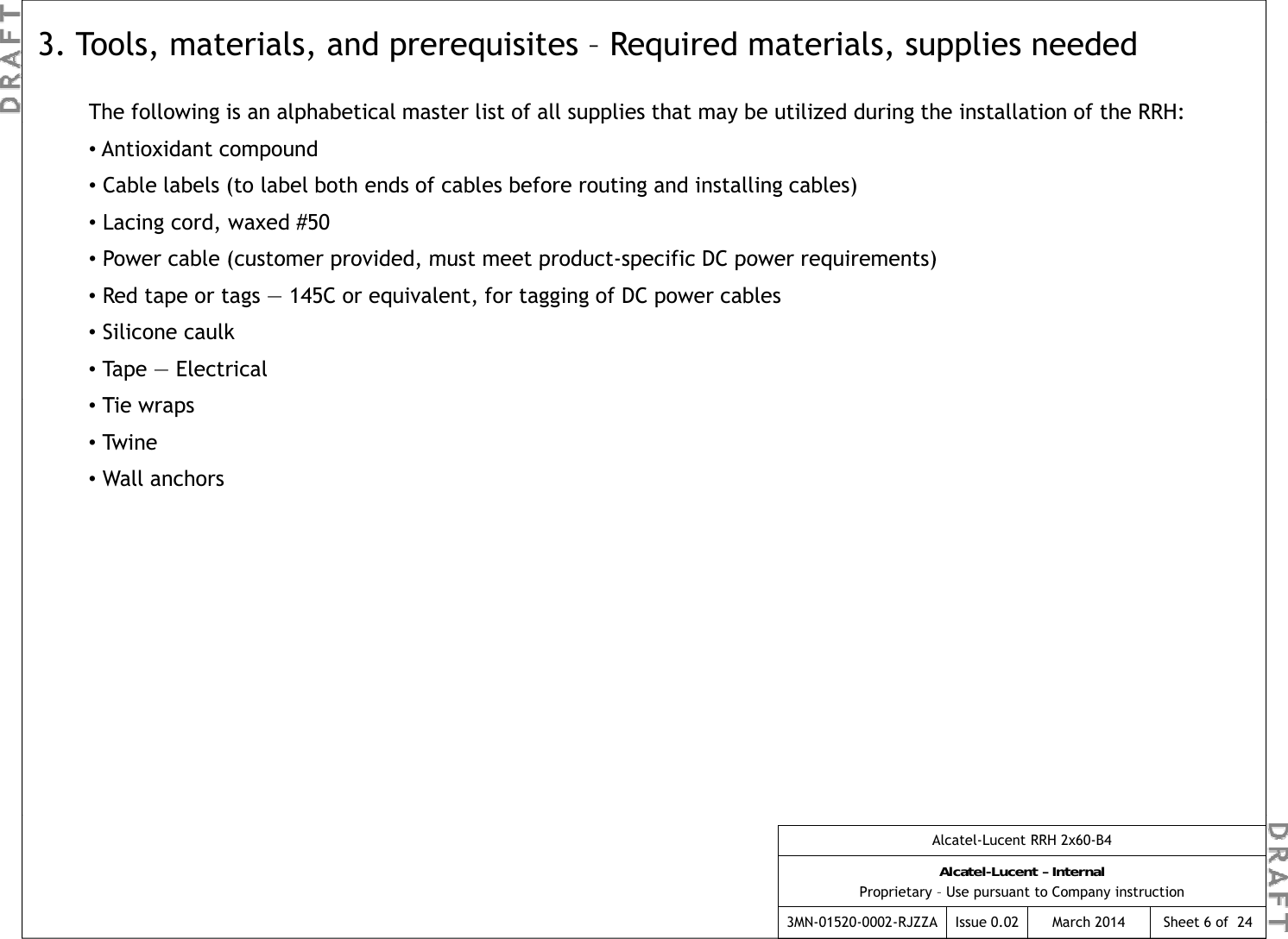
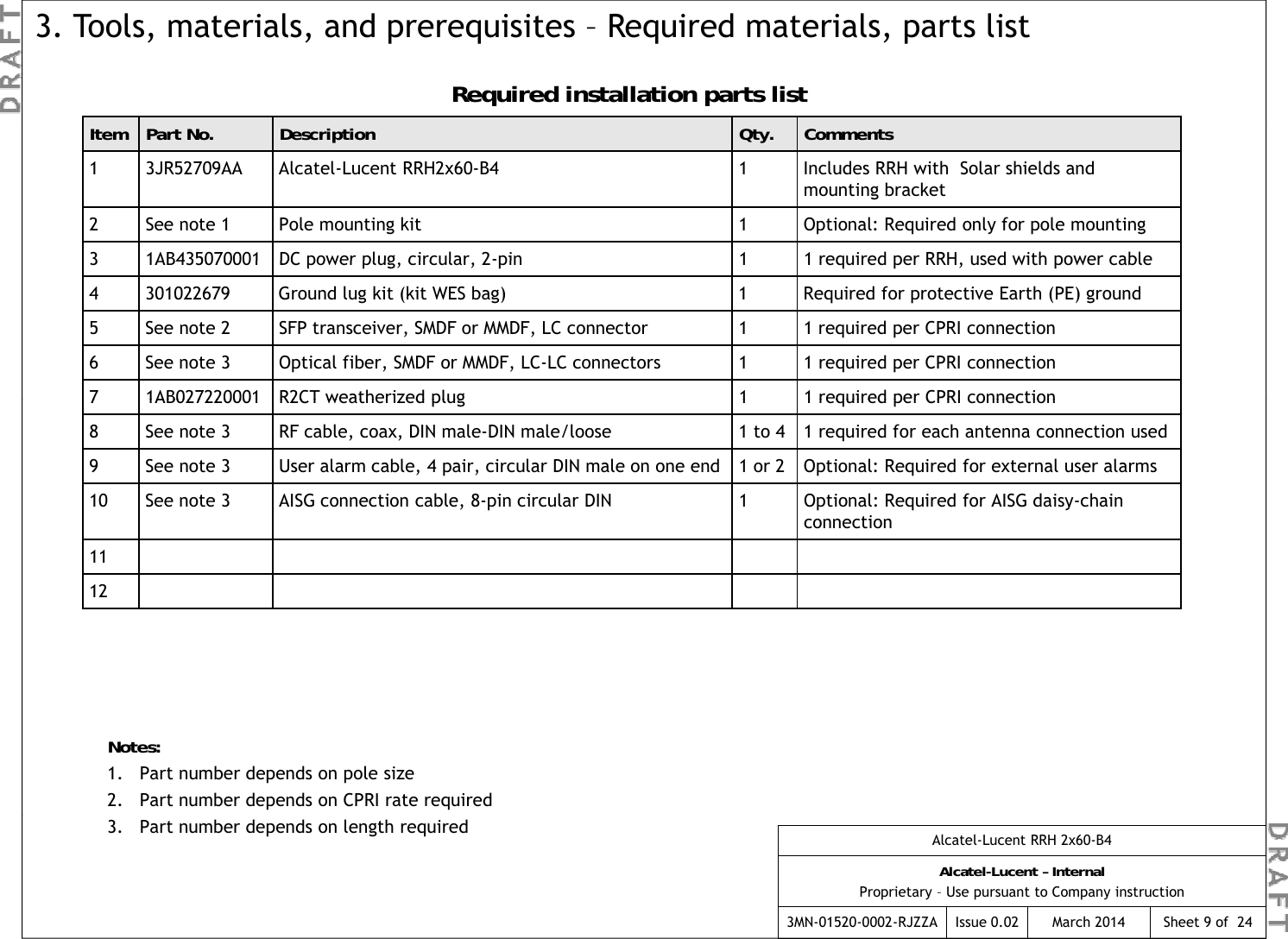
![The following is an alphabetical master list of all tools that may be utilized during the installation of the external interfaces:3. Tools, materials, and prerequisites – Required tools●Crimping tools 22-16 gauge, 10-4/0 gauge (5-120 mm2) for installation of terminal lugs and c-taps●Electrical conduit installation equipment and materials ●ESD wrist strap ●Eye protection gear — Safety goggles or glasses (R-3055) ●Gloves —Low-voltage rubber lineman's gloves (R-4285) Ggg()●Heat gun for heat shrink tubing ●Insulated hand tools (for completing electrical connections) ●M10 eye bolts or hoisting rings ●Measuring tape ●Nut driver set (Imperial) with 10-inch extension ●Nut driver set (metric) with 250-mm extension●Ohmmeter (multimeter volt/ohmmeter or equivalent) ●Ohmmeter (multi-meter, volt/ohmmeter, or equivalent) ●Screwdrivers (power and manual), flat-blade, Phillips and Torx●Small, regular, slip-joint pliers ●Tongue-and-groove, slip-joint pliers●Socket sets (Imperial and metric) various drives, including 1/4" socket for security bit●Stripping tool (for LDF4 antenna jumper cables) - part number 74Z-0-12-15 for Huber Suhner connectors; - part number ITE-7189 for Andrew connectors.●Tie wrap tool ●Torque wrenches, 2 - 34 N·m(17.7 - 300 lbf-in) ●Torque wrenches, 6 - 200 N·m (4.4 - 150 lbf-ft)●Wire cutter [capable of cutting up to 50 mm2(1/0 AWG)] ●Wire stripper●Wrench — Adjustable, (20 mm / 3/4 inch) open-end wrench (or set of fixed open-end wrenches)- If fixed open end wrenches are used, both metric (mm) and Imperial system (in) wrenches will be needed.Alcatel-Lucent RRH 2x60-B4Alcatel-Lucent – InternalProprietary – Use pursuant to Company instruction3MN-01520-0002-RJZZA Issue 0.02 March 2014 Sheet 8 of 24](https://usermanual.wiki/KMW/3JR52709A/User-Guide-2213840-Page-14.png)