User Manual

AWS RRH User Manual
1
AWS RRH User Manual
Written by
Reviewed by
Approved by
Jinhee Lee
Kshin
Michale Yoon

AWS RRH User Manual
3
1. Test Environment
1.1. Preperation List
KMW AWS RRH (Remote Radio Head 2110 ~ 2155MHz)
PSU (Power Supply Unit)
D2U (Alacaltel Lucent)
Optic transceiver 2EA Optic Cable
Ehternet Cable
Laptop computer
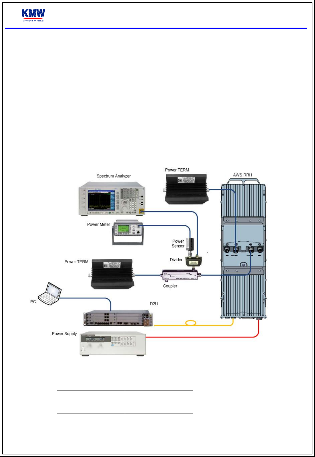
1.2. Testing Environement Configuration
PSU Setting Table
Voltage
Current Limit
Normal : -48V
14 A

AWS RRH User Manual
4
1.3. RRH Setup Procedure
Checke PSU Power 48V off
Connect PSU power to RRH Power connector
Connect D2U and RRH with Optic transceiver and Optic cable
Turn on PSU to power up RRH
Make sure computer to join RRH and D2U network.
If the computer joined the same network which BBU joined, it is able to access RRH network from the GUI.
AWS RRH User Manual
5
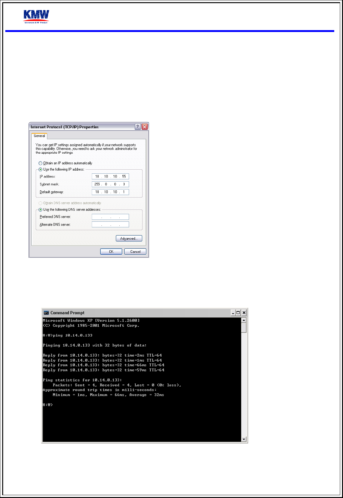
2. Network Configuration
Setup computer network configuration
IP: assigned by ALU (ex; 10.10.10.55)
Subnet mask: 255.0.0.0
Default gateway: assigned by ALU (ex; 10.10.10.1)
DNS: assigned by ALU
Test network configuration
Windows Start > Run > CMD [Enter]
C:\> ping RRH IP(10.14.0.196) [Enter]
AWS RRH User Manual
6
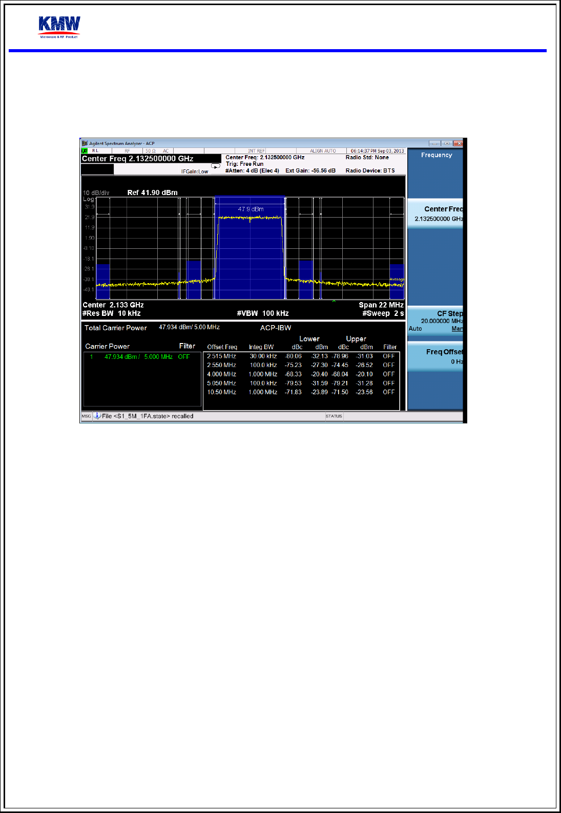
3. Output Spectrum
If you set up Signal Analyzer, you can monitor carrier power just like below image.
4. Install Guide
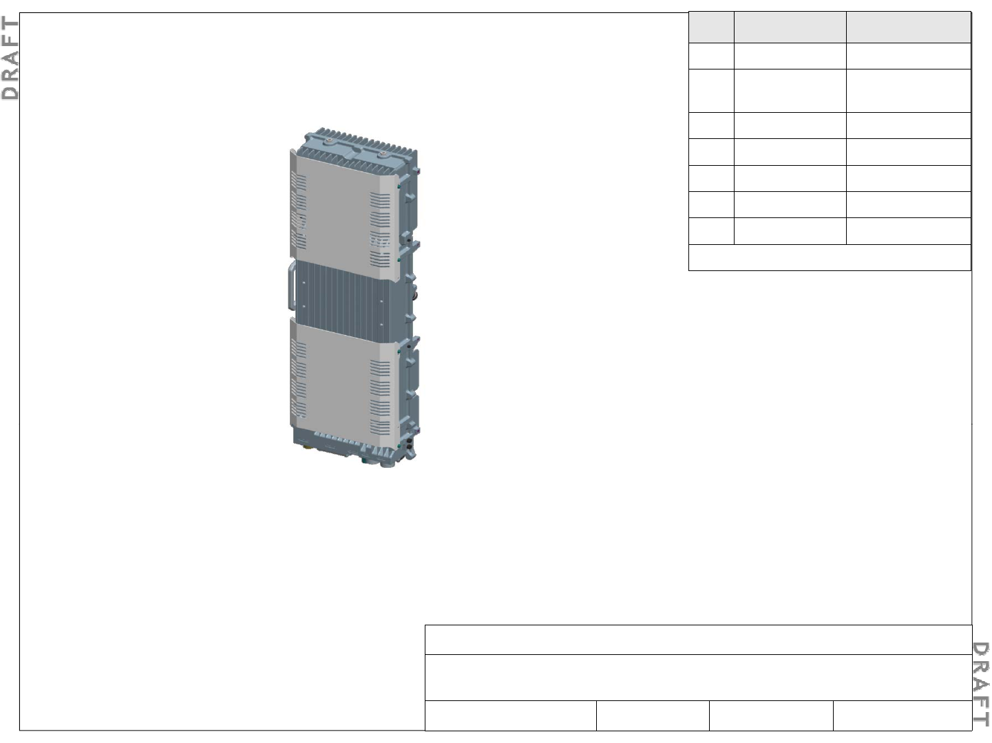
Alcatel-Lucent RRH2x60-B4 Installation Guide
Issue Date Change
0.01 March 3, 2014 First draft
0.02 March 10, 2014 Updated for
comments
Legal notice
Alcatel, Lucent, Alcatel-Lucent , and the Alcatel-Lucent logo are trademarks of Alcatel-Lucent. All other trademarks are the
property of their respective owners.
Th i f ti t d i bj t t h ith t ti Al t l
L t ibilit f
ii
Al t l
L t RRH 2 60
B4 I t ll ti G id
Th
e
i
n
f
orma
ti
on
presen
t
e
d i
s
su
bj
ec
t t
o
c
h
ange
w
ith
ou
t
no
ti
ce.
Al
ca
t
e
l
-
L
ucen
t
assumes
no
respons
ibilit
y
f
or
i
naccurac
i
es
contained herein.
Copyright © 2014 Alcatel-Lucent. All rights reserved.
Contains proprietary/trade secret information which is the property of Alcatel-Lucent and must not be made available to, or
copied or used by anyone outside Alcatel-Lucent without its written authorization.
Alcatel-Lucent RRH 2x60-B4
Alcatel-Lucent – Internal
Proprietary – Use pursuant to Company instruction
3MN-01520-0002-RJZZA Issue 0.02 March 2014
C
Al
ca
t
e
l
-
L
ucen
t RRH 2
x
60
-
B4 I
ns
t
a
ll
a
ti
on
G
u
id
e
Alcatel-Lucent – Internal
Proprietary – Use pursuant to Company instruction
3MN-01520-0002-RJZZA Issue 0.02 March 2014 Sheet 1 of 24
Document number Title
Mandatory documents
Related Documents
3MN-01520-0001-RJZZA Alcatel-Lucent RRH2x60-B4 – Site Preparation Guidelines
Document number Title
3MN-01520-0003-DEZZA Alcatel-Lucent RRH2x60-B4 – Technical Description
Related Documents
Terminology
In this document, Alcatel-Lucent Remote Radio Head 2x60-B4 is referred to by its abbreviated name, “Alcatel-
Lucent RRH2x60-B4,” its shortened name, “RRH2x60-B4,” and may be generically referred to as the Remote
Radio Head (RRH).
Radio Head (RRH).
Technical support
If you are unable to successfully complete any of the product-specific installation procedures in this document,
contact Alcatel
-
Lucent technical support before proceeding.
contact Alcatel
Lucent technical support before proceeding.
For technical support, contact your local Alcatel-Lucent customer support team. See the Alcatel-Lucent Support
web site (http://www.alcatel-lucent.com/support/) for contact information.
Alcatel-Lucent RRH 2x60-B4
Alcatel-Lucent – Internal
Proprietary – Use pursuant to Company instruction
3MN-01520-0002-RJZZA Issue 0.02 March 2014 Sheet 2 of 24
The following general precautions must be observed for installation procedures.
1. Safety - General precautions for installation procedures
WARNING
Personal injury hazard
Failure to observe these safety precautions may result in personal injury or damage to equipment.
To avoid
p
ersonal in
j
ur
y
or dama
g
e to e
q
ui
p
ment, observe the followin
g
instructions:
pygqp g
• Read and understand all instructions.
• Follow all warnings and instructions marked on this product.
• Installation and maintenance procedures must be followed and performed by trained personnel only.
• Grounding and circuit continuity is vital for safe operation of the equipment. Never operate the equipment with
di /b di d di d
groun
di
ng
/b
on
di
ng
con
d
uctor
di
sconnecte
d
.
• The equipment must be provided with a readily accessible disconnect device as part of site preparation.
• This equipment is intended for installation in restricted access locations where access is controlled or where access
can only be gained by service personnel.
Alcatel-Lucent RRH 2x60-B4
Alcatel-Lucent – Internal
Proprietary – Use pursuant to Company instruction
3MN-01520-0002-RJZZA Issue 0.02 March 2014 Sheet 3 of 24
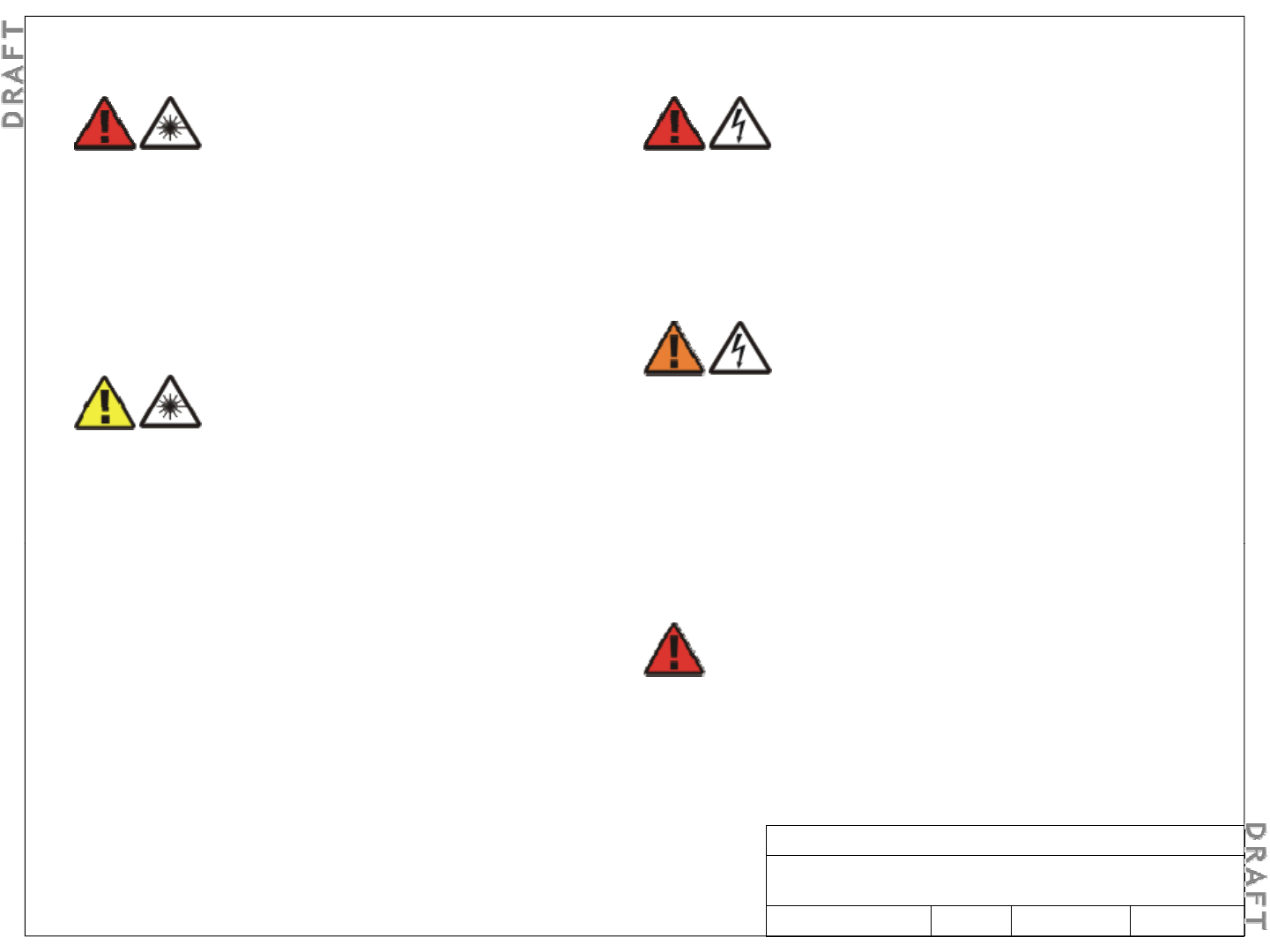
DANGER
L hd
DANGER
El t i h k h d
1. Safety – Specific hazards
L
aser
h
azar
d
This equipment operates with invisible laser radiation.
Laser radiation can cause considerable injuries to the
eyes.
Never look into the end o
f
an ex
p
osed
f
iber or into an
El
ec
t
r
i
c
s
h
oc
k h
azar
d
Working in severe weather can result in personal
injury or death and damage to the equipment.
Never install or perform maintenance during severe
weather
(
hi
g
h winds, li
g
htnin
g
, blizzards, hurricane
fpf
open optical connector when the optical source is
switched on. Always observe the laser warning
instructions.
(g g g
etc.).
WARNING
Electric shock hazard
Some parts of all electrical installations are
CAUTION
Some parts of all electrical installations are
energized. Failure to follow safe work practices and
the safety warnings may lead to bodily injury and
property damage.
For this reason, only trained and qualified personnel
(electrical workers as defined in IEC 60215 or EN 60215
Laser hazard
Use of controls or adjustments or performance of
procedures other than those specified herein may
result in hazardous laser radiation exposure.
Do not view directly into the laser beam with optical
DANGER
Li
g
htnin
g
strike hazard
(electrical workers as defined in IEC 60215 or EN 60215
+ A1 or in the National Electrical Code or in ANSI/NFPA
No. 10) may install or service the installation.
Do not view directly into the laser beam with optical
instruments such as a fiber microscope because
viewing of laser emission in excess of Class 1 limits
significantly increases the risk of eye damage.
Never look into the end of an exposed fiber or an open
connector as long as the optical source is switched on.
gg
Lightning strikes are possible during stormy weather,
and could result in death or severe injury.
Do not work on the installation itself or on the power
supply lines or antenna feeders of an antenna during
stormy weather
connector as long as the optical source is switched on.
Ensure that the optical source is switched off before
disconnecting optical fiber connectors.
Alcatel-Lucent RRH 2x60-B4
Alcatel-Lucent – Internal
Proprietary – Use pursuant to Company instruction
3MN-01520-0002-RJZZA Issue 0.02 March 2014
stormy weather
.
Sheet 4 of 24
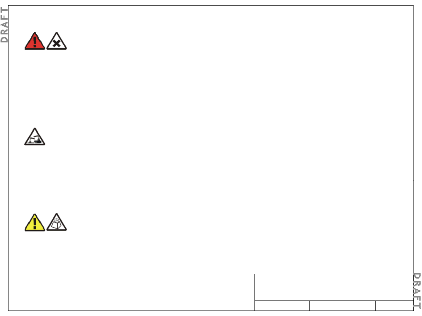
NOTICE
Tl h d
DANGER
Ni
bt h d
1. Safety – Specific hazards (continued)
T
oo
l
s
h
azar
d
Tools left in the working area can cause short circuits
during operation which can lead to the destruction of
units.
Make sure a
f
ter
f
inishin
g
y
our work that no tools,
N
ox
i
ous-su
b
s
t
ance
h
azar
d
Use of unspecified cleaning agents can result in
personal injury.
Use only specified cleaning agents. Never use
f
lammable solvents.
ff gy
testing equipment, flashlights, etc., have been left in
or on the equipment.
NOTICE E
q
ui
p
ment safet
y
f
Always ensure there is adequate ventilation in the
work area and wear the appropriate personal
protective equipment.
Corrosive-substance hazard
Cleaning plastic containers and lids with abrasive and
aggressive cleaning agents may cause permanent
damage.
D t l t ffi b i i
qp y
Safety information for this equipment can be found on
various Caution, Warning, Danger, information labels or
instructions affixed to or included with the Alcatel-
Lucent RRH2x60-B4, its internal assemblies or included
within this document. Informational and cautionar
y
D
o
no
t
use
so
l
ven
t
s,
para
ffi
n,
a
b
ras
i
ve
or
aggress
i
ve
cleaning fluids, abrasive or aggressive antiseptic
agents or abrasive or aggressive materials.
y
labels may appear near the item they address or may
be grouped in a single location on the equipment.
Warnings are typically adjacent to the hazard that is
noted on the label. The instructions, cautions and
warnings found on these labels must be understood and
bdbll lldhh
CAUTION
fhd
o
b
serve
d
b
y a
ll
personne
l
invo
l
ve
d
wit
h
t
h
e equipment
installation and maintenance.
Li
f
ting
h
azar
d
Lifting this equipment by yourself can result in injury
due to the size and weight of the equipment.
Always use at least two people or a lifting device to
move or
p
osition this e
q
ui
p
ment.
Alcatel-Lucent RRH 2x60-B4
Alcatel-Lucent – Internal
Proprietary – Use pursuant to Company instruction
3MN-01520-0002-RJZZA Issue 0.02 March 2014 Sheet 5 of 24
pqp

The followin
g
is an al
p
habetical master list of all su
pp
lies that ma
y
be utilized durin
g
the installation of the RRH:
3. Tools, materials, and prerequisites – Required materials, supplies needed
gp pp y g
•Antioxidant compound
•Cable labels (to label both ends of cables before routing and installing cables)
•Lacing cord, waxed #50
•
Power cable (customer provided must meet product
-
specific DC power requirements)
•
Power cable (customer provided
,
must meet product
-
specific DC power requirements)
•Red tape or tags — 145C or equivalent, for tagging of DC power cables
•Silicone caulk
•Tape — Electrical
Ti
•
Ti
e
wraps
•Tw i n e
•Wall anchors
Alcatel-Lucent RRH 2x60-B4
Alcatel-Lucent – Internal
Proprietary – Use pursuant to Company instruction
3MN-01520-0002-RJZZA Issue 0.02 March 2014 Sheet 6 of 24
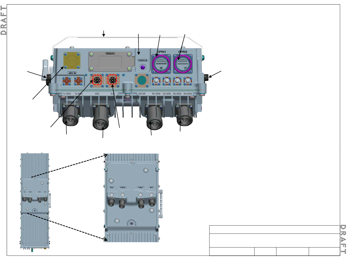
Solar Shield CPRI-1
(primary)
CPRI-2
(secondary)
Status LED
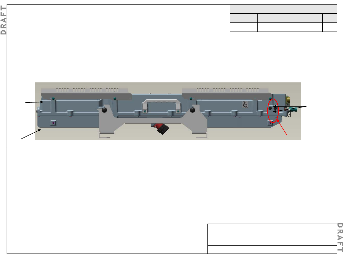
2. Product overview – physical interfaces
Bottom view
GND GND
-48V
DC IN
alarms ports
AISG
(output) Rx3 TxRx2
Rx4
TxRx1
Notes:
Solar shield now shown in these views
GND = Protective Earth (PE) ground located on
GND = Protective Earth (PE) ground
,
located on
lower right side and lower right side of RRH (when
facing front of RRH)
Alcatel-Lucent RRH 2x60-B4
Alcatel-Lucent – Internal
Proprietary – Use pursuant to Company instruction
3MN-01520-0002-RJZZA Issue 0.02 March 2014 Sheet 7 of 24
Rear view

The following is an alphabetical master list of all tools that may be utilized during the installation of the
external interfaces:
3. Tools, materials, and prerequisites – Required tools
●Crimping tools 22-16 gauge, 10-4/0 gauge (5-120 mm2) for installation of terminal lugs and c-taps
●Electrical conduit installation equipment and materials ●ESD wrist strap
●Eye protection gear — Safety goggles or glasses (R-3055)
●
Gloves
—L
ow
-
voltage
r
ubbe
r
l
in
e
m
a
n'
s gloves (R
-42
85)
G
gg(
)
●Heat gun for heat shrink tubing ●Insulated hand tools (for completing electrical connections)
●M10 eye bolts or hoisting rings ●Measuring tape
●Nut driver set (Imperial) with 10-inch extension ●Nut driver set (metric) with 250-mm extension
●
Ohmmeter (multi
meter volt/ohmmeter or equivalent)
●
Ohmmeter (multi
-
meter
,
volt/ohmmeter
,
or equivalent)
●Screwdrivers (power and manual), flat-blade, Phillips and Torx
●Small, regular, slip-joint pliers ●Tongue-and-groove, slip-joint pliers
●Socket sets (Imperial and metric) various drives, including 1/4" socket for security bit
●Stripping tool (for LDF4 antenna jumper cables) - part number 74Z-0-12-15 for Huber Suhner connectors;
- part number ITE-7189 for Andrew connectors.
●Tie wrap tool ●Torque wrenches, 2 - 34 N·m(17.7 - 300 lbf-in)
●Torque wrenches, 6 - 200 N·m (4.4 - 150 lbf-ft)
●Wire cutter [capable of cutting up to 50 mm2(1/0 AWG)] ●Wire stripper
●Wrench — Adjustable, (20 mm / 3/4 inch) open-end wrench (or set of fixed open-end wrenches)
- If fixed open end wrenches are used, both metric (mm) and Imperial system (in) wrenches will be
needed.
Alcatel-Lucent RRH 2x60-B4
Alcatel-Lucent – Internal
Proprietary – Use pursuant to Company instruction
3MN-01520-0002-RJZZA Issue 0.02 March 2014 Sheet 8 of 24
Required installation parts list
3. Tools, materials, and prerequisites – Required materials, parts list
Item Part No. Description Qty. Comments
1 3JR52709AA Alcatel-Lucent RRH2x60-B4 1 Includes RRH with Solar shields and
mounting bracket
2 See note 1 Pole mounting kit 1 Optional: Required only for pole mounting
3
1AB435070001
DC power plug circular 2
-
pin
1
1 required per RRH used with power cable
3
1AB435070001
DC power plug
,
circular
,
2
-
pin
1
1 required per RRH
,
used with power cable
4 301022679 Ground lug kit (kit WES bag) 1 Required for protective Earth (PE) ground
5 See note 2 SFP transceiver, SMDF or MMDF, LC connector 1 1 required per CPRI connection
6 See note 3 Optical fiber, SMDF or MMDF, LC-LC connectors 1 1 required per CPRI connection
7
1AB027220001
R2CT weatherized plug
1
1
required per CPRI connection
7
1AB027220001
R2CT weatherized plug
1
1
required per CPRI connection
8 See note 3 RF cable, coax, DIN male-DIN male/loose 1 to 4 1 required for each antenna connection used
9 See note 3 User alarm cable, 4 pair, circular DIN male on one end 1 or 2 Optional: Required for external user alarms
10 See note 3 AISG connection cable, 8-pin circular DIN 1 Optional: Required for AISG daisy-chain
connection
11
12
Notes:
1. Part number depends on pole size
2. Part number depends on CPRI rate required
Alcatel-Lucent RRH 2x60-B4
Alcatel-Lucent – Internal
Proprietary – Use pursuant to Company instruction
3MN-01520-0002-RJZZA Issue 0.02 March 2014
3. Part number depends on length required
Sheet 9 of 24
Verify site preparation and physical installation are completed: (see Alcatel-Lucent RRH2x60-B4 – Site
Preparation Guidelines, 3MN-01520-0001-RJZZA):
3. Tools, materials, and prerequisites – Prerequisites
Before installation of the Alcatel-Lucent RRH2x60-B4 site can begin, site preparation must be completed.
The following site preparation general requirements must be met before the installation of the Alcatel-Lucent
RRH2x60-B4 can begin:
●Adequate clearance must be provided for service access
●DC electric service (with a readily accessible disconnect device ) must be installed
●User alarm facilities must be installed ●Grounding electrode system must be installed and tested
●RF and antenna runs must be installed (if required) ●Surge protection for antennas must be installed (if required)
●Tower light power must be installed (if required) ●Tower light alarm must be installed (if required)
●The environment must comply with limits listed under Environmental requirements in the Alcatel-Lucent
RRH2x60-B4 – Site Preparation Guidelines, 3MN-01520-0001-RJZZA
●Cable supports and racks must be installed ●Conduit for DC power must be installed when applicable
Installation
p
rocedure checklist
Done N/A Task
5-1: Install RRH on a pole
5-2: Install RRH on a wall
5-3: Procedure to chan
g
e from T
yp
e A confi
g
uration to T
yp
e B
p
gypg
yp
5-4: Connect protective earth (PE) ground
5-5: Connect optical fiber cables
5-6: Route and connect user alarm cables (optional)
5-7: Route and connect AISG cable
(
o
p
tional
)
Alcatel-Lucent RRH 2x60-B4
Alcatel-Lucent – Internal
Proprietary – Use pursuant to Company instruction
3MN-01520-0002-RJZZA Issue 0.02 March 2014 Sheet 10 of 24
(p )
5-8: Route and connect RF cables (optional)
5-9: Connect DC power cable
5-10: Final checks prior to installation
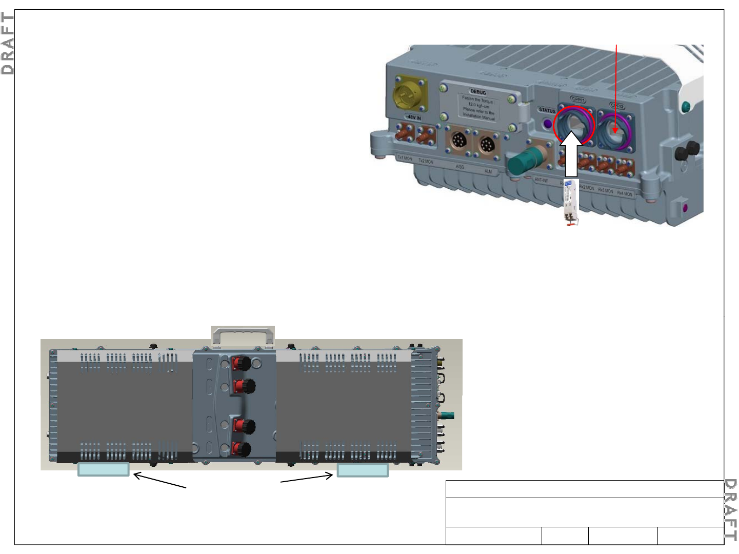
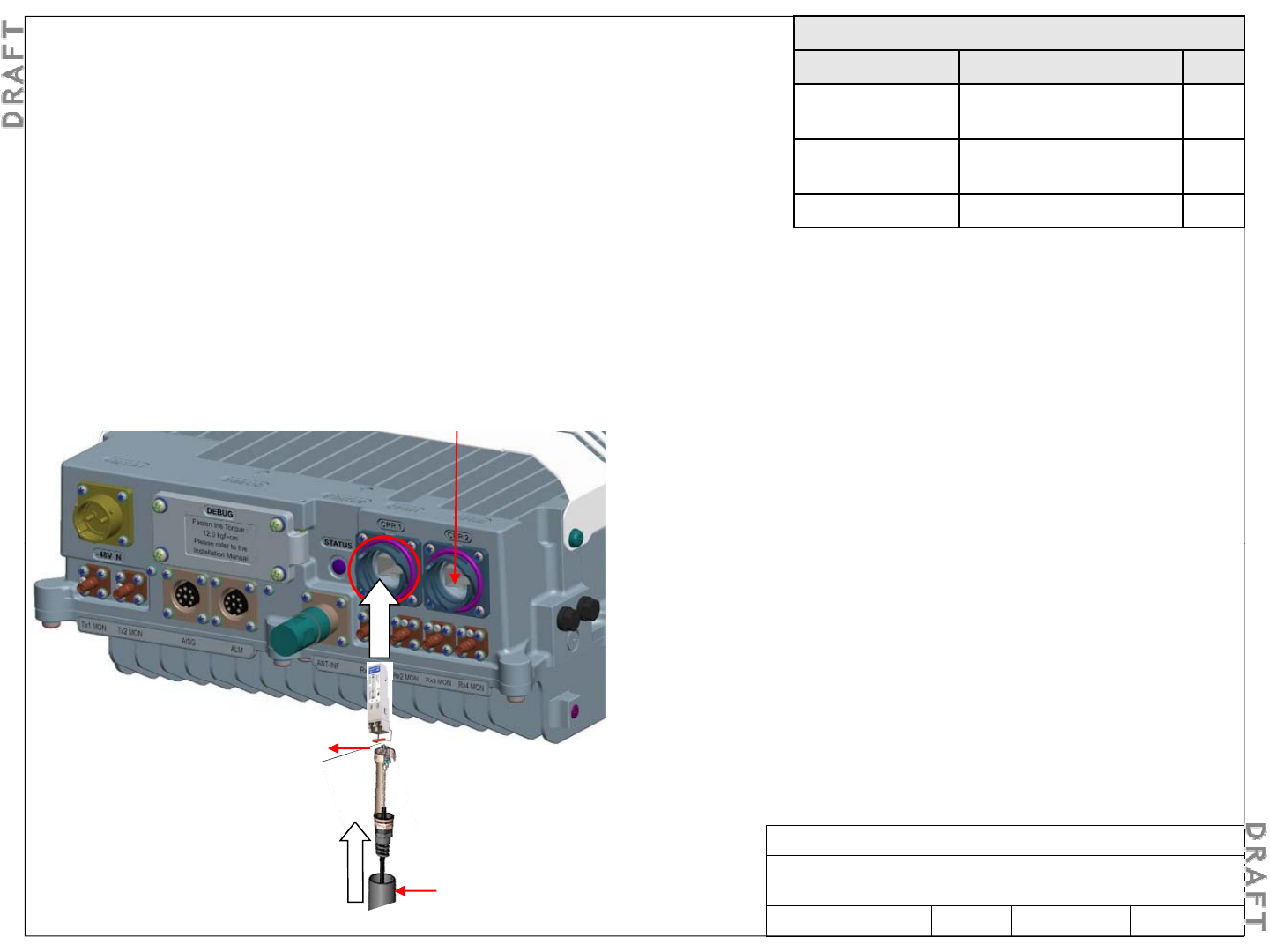
4-1. Pre-installation steps - Preparing the RRH CPRI-2
Step 1
I1
Step 1
Remove the optical port cover.
Step 2
Install the optical transceiver in the right slot.
NOTE:
if only one optical port is used insert the
CPR
Note: Clean and inspect the
LC connectors on the CPRI
NOTE:
if only one optical port is used
,
insert the
transceiver in CPRI1
Step 3
Place the cover of the optical port back to protect the
port.
LC connectors on the CPRI
fiber optic cable before
connecting to SFP.
4-2. Handling the RRH
Alcatel-Lucent RRH 2x60-B4
Alcatel-Lucent – Internal
Proprietary – Use pursuant to Company instruction
3MN-01520-0002-RJZZA Issue 0.02 March 2014 Sheet 11 of 24
1- Always use the handle fitted onto the RRH body
2- Protect the side facing the ground with packing foam
Packing Foam
Note: The RRH is shipped with the Wall Mounting Bracket
and the solar shields installed
(
in T
yp
e A confi
g
uration.
)
Required materials
Part No. Description Qty.
3JR52709AA Alcatel-Lucent RRH2x60-B4 1
Depends on
Pole mounting kit
1
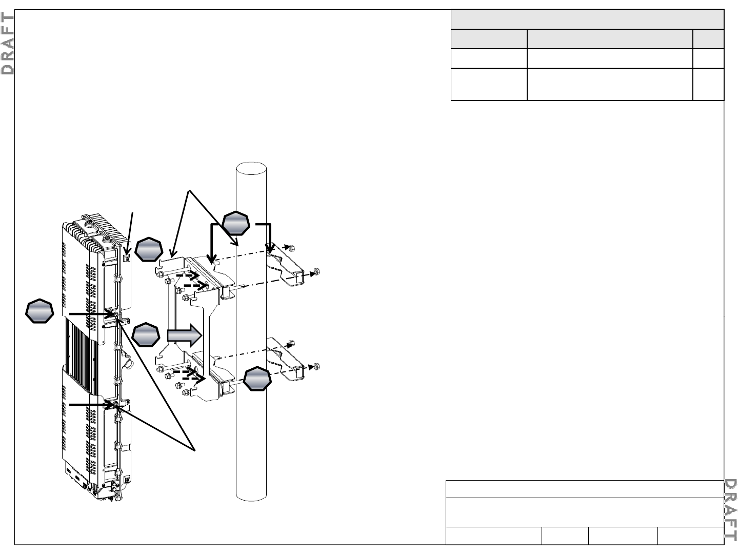
5-1. Install RRH on a pole
(yp g )
Step 1
Remove the mounting bracket from the RRH by loosening
the four M8 side screws (see arrows). Do not completely
remove the screws from the holes.
Depends on
pole size
Pole mounting kit
1
S 2
St
ep
2
Attach half of each pole clamp to the back of the Mounting
Bracket using two M10x25 screws in the center holes, upper
and lower.
Step 3
4
4
Mounting
Bracket
Pole clamp
Step 3
With the M10 flanged nut installed on one end of the M10
threaded rod, pass the threaded rod through both the upper
and lower outer holes of the Mounting Bracket.
Step 4
Pl th bl i t th l d l th
1
1
2
2
Pl
ace
th
e
assem
bl
y
aga
i
ns
t th
e
po
l
e
an
d
p
l
ace
th
e
rear
halves of each pole clamp, and secure with M10 flanged
nuts.
Note: Ensure the mounting bracket is level.
Step 5
1
3
3
5
5
Step 5
Hang the RRH on the Mounting Bracket and tighten the four
M8 side screws.
M8 Side screws
(Loosely
Alcatel-Lucent RRH 2x60-B4
Alcatel-Lucent – Internal
Proprietary – Use pursuant to Company instruction
3MN-01520-0002-RJZZA Issue 0.02 March 2014 Sheet 12 of 24
(Loosely
installed
before hanging)
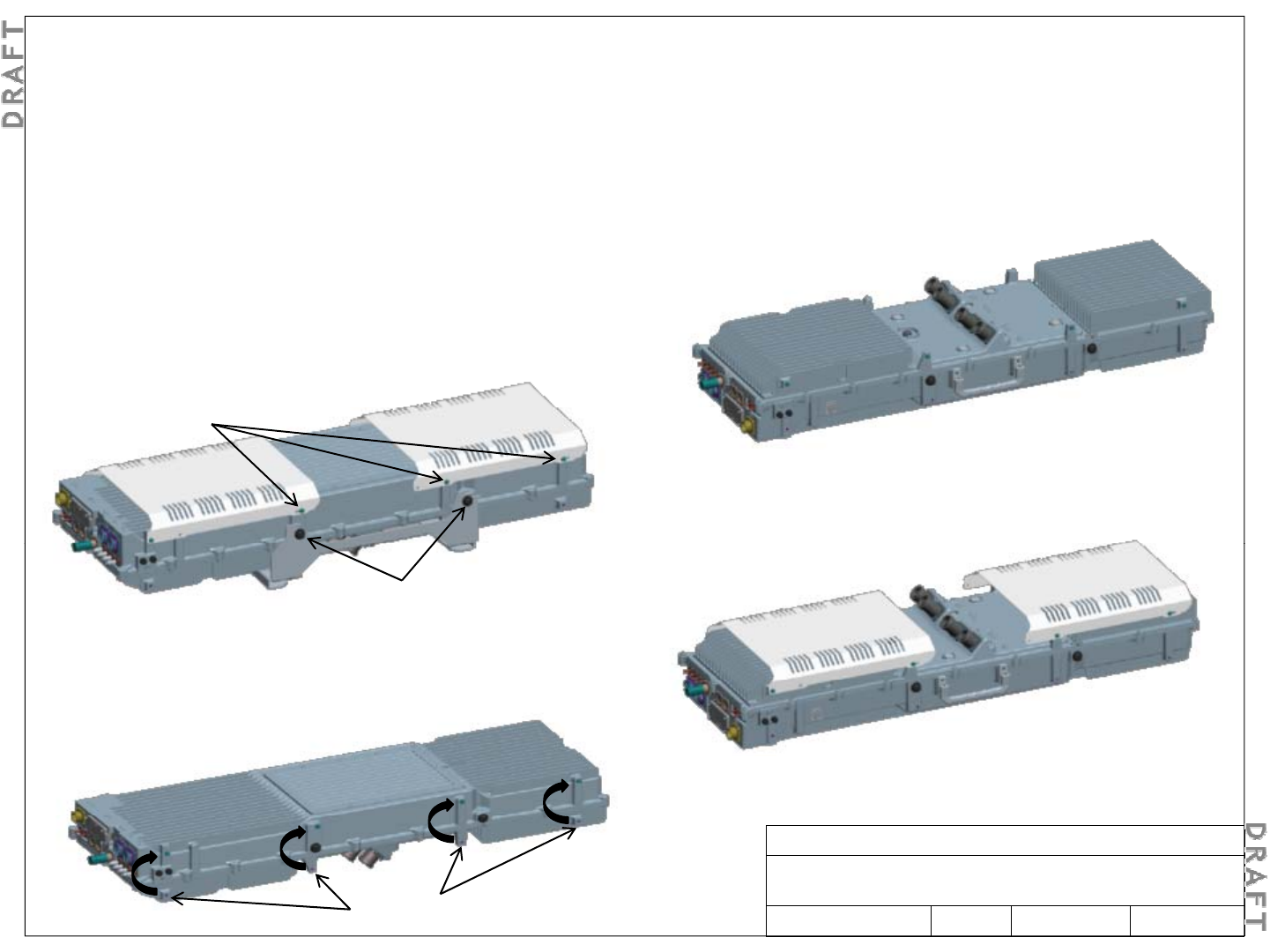
5-2. Procedure to change from Type A configuration to Type B
Note:
The RRH is shipped with the Mounting Bracket installed in Type A configuration (on the same side as the
Note:
The RRH is shipped with the Mounting Bracket installed in Type A configuration (on the same side as the
antenna connectors). To convert to Type B configuration (Mounting Bracket on opposite side of antenna connectors).
Step 4
Flip over the RRH so the antenna connector side is up.
Step 1
Remove the mounting bracket from the RRH by loosening the
four M8 side screws. Do not completely remove the screws
from the holes
M5
from the holes
.
Step 2
Remove the solar shields by removing four M5 screws for
each solar shield. Keep the screws.
M5
Screws
Step 5
Install the solar shield using four M5 screws for each solar
M8
Screws
Step 3
Remove the 8 M5 “filler” screws , then insert the 8 M5
shield.
“filler” screws in the holes in the locations above where
they were installed.
Alcatel-Lucent RRH 2x60-B4
Alcatel-Lucent – Internal
Proprietary – Use pursuant to Company instruction
3MN-01520-0002-RJZZA Issue 0.02 March 2014
M5 “filler” Screws Sheet 13 of 24
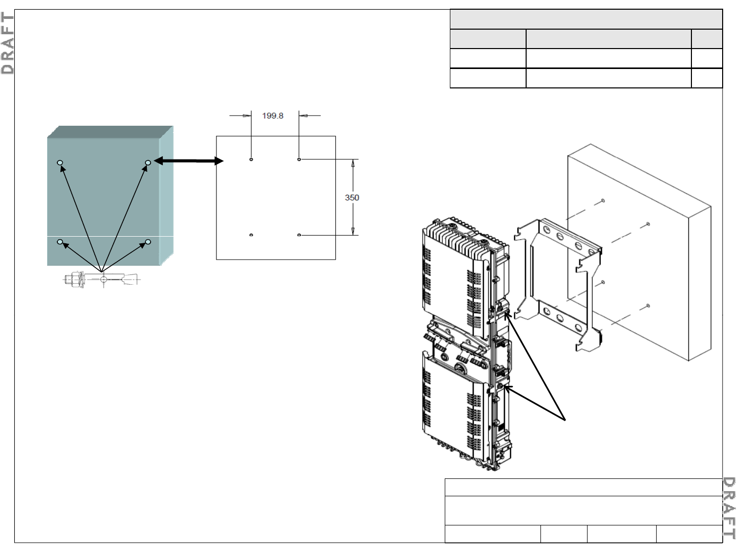
Note: The RRH is shipped with the wall Mounting Bracket installed (in
Type A configuration). For wall mounting, the Mounting Bracket must be
td t T B fig ti S 4
2 P d t h g f
Required materials
Part No. Description Qty.
3JR52709AA Alcatel-Lucent RRH2x60-B4 1
N/A
Wall
anchors (customer provided)
4
5-3. Install RRH on a wall
conver
t
e
d t
o
T
ype
B
con
fig
ura
ti
on.
S
ee
4
-
2 P
roce
d
ure
t
o
c
h
an
g
e
f
rom
Type A configuration to Type B.
N/A
Wall
anchors (customer provided)
4
Step 5
Torque each M8 side screw (4 total) to 15.3
Nm (135 in-lb).
Step 1
Mounting bracket
(front view)
Install a wall anchor in each mounting hole, tighten each anchor nut
to secure anchor to wall, and remove anchor nut and washers.
Step 2
Install wall mounting bracket on anchor studs, install anchor
M8 Side screws
(Loosely installed
before hanging)
washers and nuts, tighten each anchor nut to secure wall mounting
bracket to wall.
Note: Ensure the mounting bracket is level.
Step 3
Loosely install M8 side mounting screws on both sides of the RRH.
Alcatel-Lucent RRH 2x60-B4
Alcatel-Lucent – Internal
Proprietary – Use pursuant to Company instruction
3MN-01520-0002-RJZZA Issue 0.02 March 2014
Loosely install M8 side mounting screws on both sides of the RRH.
Step 4
Carefully raise RRH into position on mounting by inserting the M8
side screws into the slots on mounting bracket.
Sheet 14 of 24
Required materials
Part No. Description Qty.
301022679 Ground lug kit (kit WES bag) 1
4-4. Connect protective Earth (PE) ground
Ste
p
1
p
Route the 35 mm2(#2 AWG) ground cable pigtail from
the ground system (installed during site preparation) to
the PE ground pad located on the lower right side or the
lower left side of the RRH.
Alcatel
-
Lucent RRH 2x60
-
B4 PE ground
Alcatel
Lucent RRH 2x60
B4 PE ground
Front
side M6 bolts
Wall or
l id
GND
Step 2
At the RRH end, cut the ground cable to the proper
length and strip the end of the cable.
Step 4
Connect the ground lug to the RRH PE ground pad
using the supplied M6 bolts, lock washers, and flat
po
l
e
s
id
e
Step 3
Crimp the 35 mm2(#2 AWG) two-hole lug (from the
ground lug kit) onto the end of the ground cable. Clean
the contact surface area and use antioxidant to prevent
id ti
washers. Use antioxidant at the ground pad.
Step 5
Torque each bolt to 5.6 N·m (50 lbf-in).
Alcatel-Lucent RRH 2x60-B4
Alcatel-Lucent – Internal
Proprietary – Use pursuant to Company instruction
3MN-01520-0002-RJZZA Issue 0.02 March 2014 Sheet 15 of 24
ox
id
a
ti
on.
Required materials
Part No. Description Qty.*
SFP transceiver, SMDF or
MMDF , LC connector
1
NOTICE
4-5. Connect optical fiber cables
Depends on length Optical fiber, SMDF, LC-LC
connectors
1
1AB027220001 R2CT weatherized plug 1
*Notes:
1
Th CPRI d i h i fi ti i t
Protect fiber cable
Mishandling fiber optic cable can result in damaged and non-
functioning cables.
The optical cable is very sensitive, take the maximum precaution when
1
.
Th
e
CPRI d
a
i
sy
c
h
a
i
n
con
fi
gura
ti
on
i
s
no
t
supported in the initial release (LR14.1.L); it will
be supported in a future release.
2. When the CPRI daisy chain configuration is
supported and needed, Qty = 2 for all items and
repeat Steps 1 through 3to connect the CPRI-2
port to the next RRH
installing it. The optical fiber should be protected in solid pipe. Do not
use cable ties on the fiber cable. Do not cut this cable on site, excess
length should be coiled inside the eNodeB. The fiber optic connector
should be protected by a cap when not being used. Respect the
bending radius during the manipulation of optical cable (82.5 mm).
port to the next RRH
.
Step 1
If not previously installed, install and route a fiber optic
cable from the CPRI-1 port on the bottom of the RRH to the
eNodeB.
CPRI-2
Note: The CPRI-1 port is accessed with the left hand
from the rear (pole-side) of the RRH.
Step 2
Remove protective cover from CPRI-1 port.
CPRI-1
Step 3
If not previously installed, remove protective cover from
SFP, insert into CPRI-1 port, and lock SFP into place.
Note: Clean and inspect the LC
connectors on the CPRI fiber optic
cable before connecting to SFP.
Alcatel-Lucent RRH 2x60-B4
Alcatel-Lucent – Internal
Proprietary – Use pursuant to Company instruction
3MN-01520-0002-RJZZA Issue 0.02 March 2014 Sheet 16 of 24
R2CT coupling nut
Ste
p
4
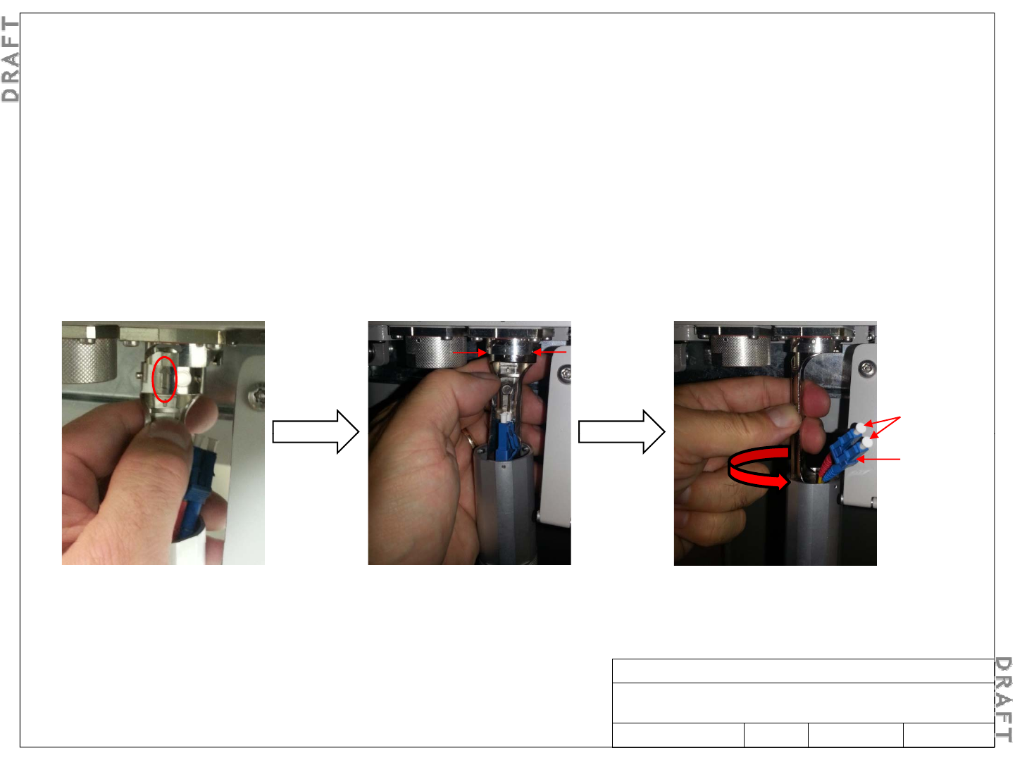
5-4. Connect optical fiber cables (continued)
p
Using the assembly instructions provided with the R2CT weatherized plug, assemble the R2CT plug onto the SMDF optical
fiber and connect to CPRI-1 port.
Step 4A
Using your left hand, connect the R2CT plug body to the CPRI-1 port receptacle as follows:
Align arrow on plug body with
alignment mark on receptacle.
Insert plug body bayonet pins
into slots on receptacle.
Rotate the plug body counter-
clockwise to lock it into place.
Protective
covers
LC
connector
covers
The base of the plug body should be
on the left, as shown in the picture.
Alcatel-Lucent RRH 2x60-B4
Alcatel-Lucent – Internal
Proprietary – Use pursuant to Company instruction
3MN-01520-0002-RJZZA Issue 0.02 March 2014 Sheet 17 of 24
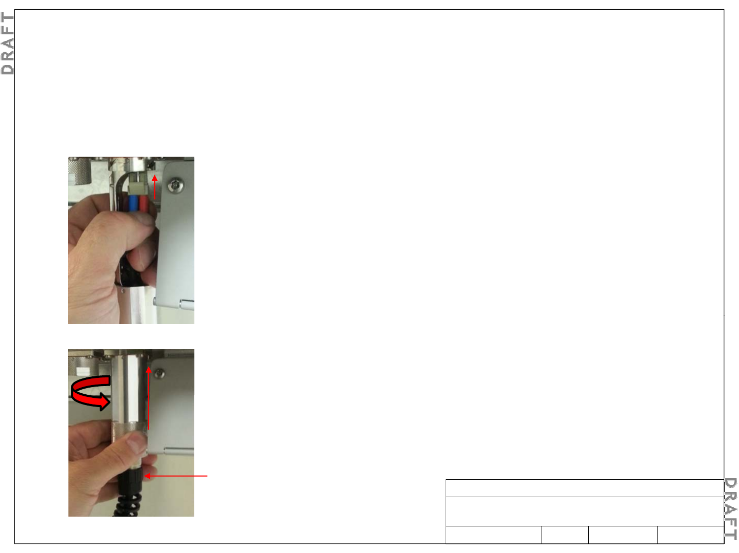
Ste
p
4B
5-5. Connect optical fiber cables – Step 4 (continued)
p
Remove the protective covers from the LC connector. Clean and inspect the LC connectors on the CPRI fiber optic cable.
Step 4C
Using your left hand, connect the fiber optic cable to the CPRI1 port SFP transceiver as follows:
Gently insert the LC connector into the SFP
transceiver until it “clicks” into place.
Gently pull on the LC connector to verify
that it is locked into place.
Step 4D
Using your left hand, carefully slide the coupling nut over the R2CT plug body and
rotate counter
-
clockwise to lock it into place on the
CPRI1
port receptacle
rotate counter
clockwise to lock it into place on the
CPRI1
port receptacle
.
Step 4E
If not secured previously, manually thread the nut spiral onto the R2CT plug body and
torque to approximately 3.5 N·m (31 lbf-in).
Nt i l
Alcatel-Lucent RRH 2x60-B4
Alcatel-Lucent – Internal
Proprietary – Use pursuant to Company instruction
3MN-01520-0002-RJZZA Issue 0.02 March 2014 Sheet 18 of 24
N
u
t
sp
i
ra
l
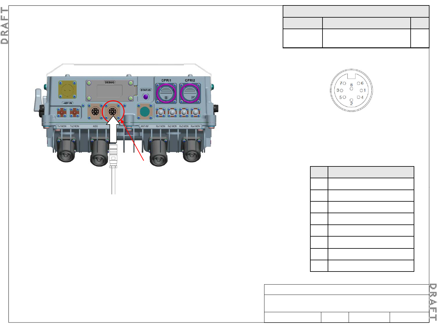
Step 1
Install and route the alarm cables from the alarm ports to the alarm
Required materials
Part No. Description Qty.
Depends on
length
User alarm cable, 4 pair,
circular DIN male on one end
1 or
2
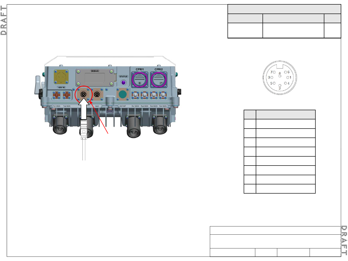
5-6. Route and connect user alarm cables (optional)
Install and route the alarm cables from the alarm ports to the alarm
distribution frame. Connector pin configuration
Step 5
Plug the alarm cable connectors into the alarm ports
and hand tighten the outer connector shell to secure
h bl
Step 2
Pin Designation
1 User_ALM_4_P
Alarm cable terminal configuration
alarm
(output)
t
h
e
ca
bl
es.
Step 2
Connect the alarm cables to the distribution frame.
Step 3
Using an ohmmeter or multi-meter, verify the continuity between the alarm
cable connector pins and the distribution frame (DF)
2 User_ALM_3_RTN
3 User_ALM_1_P
4 User_ALM_2_RTN
5 User_ALM_2_P
cable connector pins and the distribution frame (DF)
.
Note: This measurement is performed on the alarm cable connector
(RRH side) with a loop back of each pair (one by one) on the alarm DF
side. Using a multi-meter, check that no short circuit appears between
each pair and the shielding wires.
6 User_ALM_4_RTN
7 User_ALM_3_P
8 User_ALM_1_RTN
Alcatel-Lucent RRH 2x60-B4
Alcatel-Lucent – Internal
Proprietary – Use pursuant to Company instruction
3MN-01520-0002-RJZZA Issue 0.02 March 2014
Step 4
Remove the protective cover from the alarm ports on the RRH.
Sheet 19 of 24
Ste
p
1
Required materials
Part No. Description Qty.*
Depends on
length
AISG connection cable, 8-
pin circular DIN
1
5-7. Route and connect AISG cable (optional)
p
Install and route the AISG cable from the AISG port on the bottom of the
RRH to the respective AISG controller or external antenna line device
(ALD) port. Connector pin configuration
AISG cable terminal configuration
AISG
(output)
Pin Designation
1 +12 V DC output
2 -48 V DC output
3 RS485 B
S 2
Note: AISG OUT ports have
female pins.
4 RS485 GND
5 RS485 A
6 +10 V to +30 V DC output
7 DC return
S
tep
2
Remove the protective cover from the AISG port on the RRH.
Note: To connect an AISG cable to the AISG port, plug the AISG
cable into the AISG port and hand tighten the outer connector
shell to secure the cable.
8 N/C
Alcatel-Lucent RRH 2x60-B4
Alcatel-Lucent – Internal
Proprietary – Use pursuant to Company instruction
3MN-01520-0002-RJZZA Issue 0.02 March 2014 Sheet 20 of 24
Step 3
Connect the AISG output port to the AISG IN port of another ALD.
Ste
p
1
Required materials
Part No. Description Qty.
Depends on
length
RF cable, coax, DIN male-
DIN male/loose
1 to 4
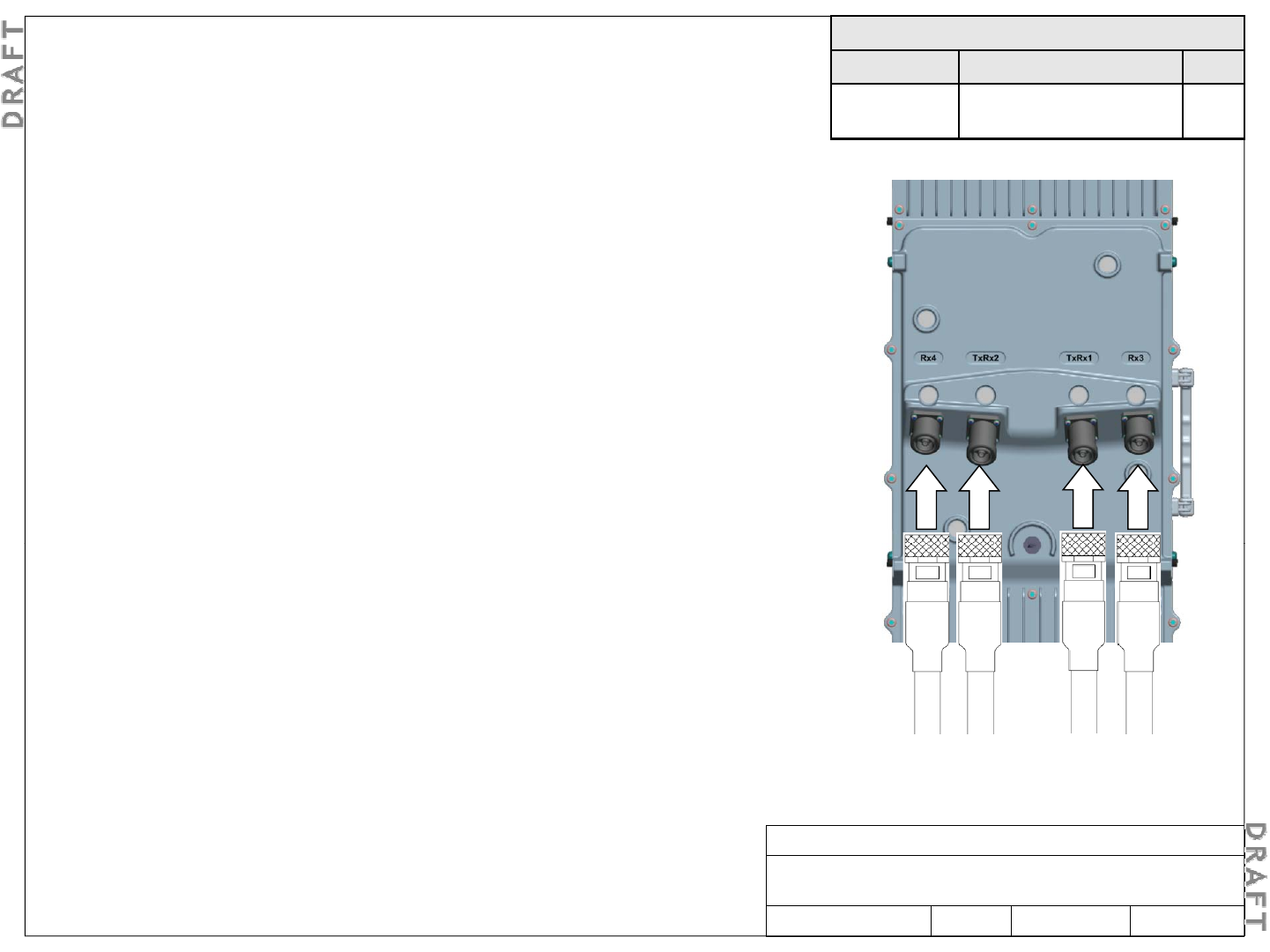
5-8. Route and connect RF cables (optional)
p
Install and route the RF cables to the RF ports on the top
of the RRH.
Important! Ensure that RF cable shield grounding
has been completed for all antenna cables.
Step 2
Step 2
Providing adequate slack, cut each cable so it reaches its
corresponding RF antenna connector or, if applicable, its
corresponding RF surge protector.
Step 3
Terminate the end of each cable with the supplied 7/16
DIN connector.
Step 4
Remove the protective covers from the RF ports on the
RRH
Rx3
Rx4
TxRx2
TxRx1
RRH
.
Step 5
Connect each RF antenna cable to its corresponding RF
port on the RRH.
Note:
RF surge protectors are optional
Note:
RF surge protectors are optional
.
Step 6
Torque each 7/16 male DIN connector to 25 N·m (221 lbf-
in), at both ends (RRH and antenna) of each RF cable.
Important!
Hold the body of the connector (part
Step 7
Secure the RF cables along their route.
Alcatel-Lucent RRH 2x60-B4
Alcatel-Lucent – Internal
Proprietary – Use pursuant to Company instruction
3MN-01520-0002-RJZZA Issue 0.02 March 2014
Important!
Hold the body of the connector (part
connected to the coaxial cable) with a 22 mm open-
end wrench. Torque the rotating nut with a 32 mm
open-end wrench.
Sheet 21 of 24
Required materials
Part No. Description Qty.
1AB435070001 DC power plug, circular, 2-pin 1
N/A
Power cable customer provided
1
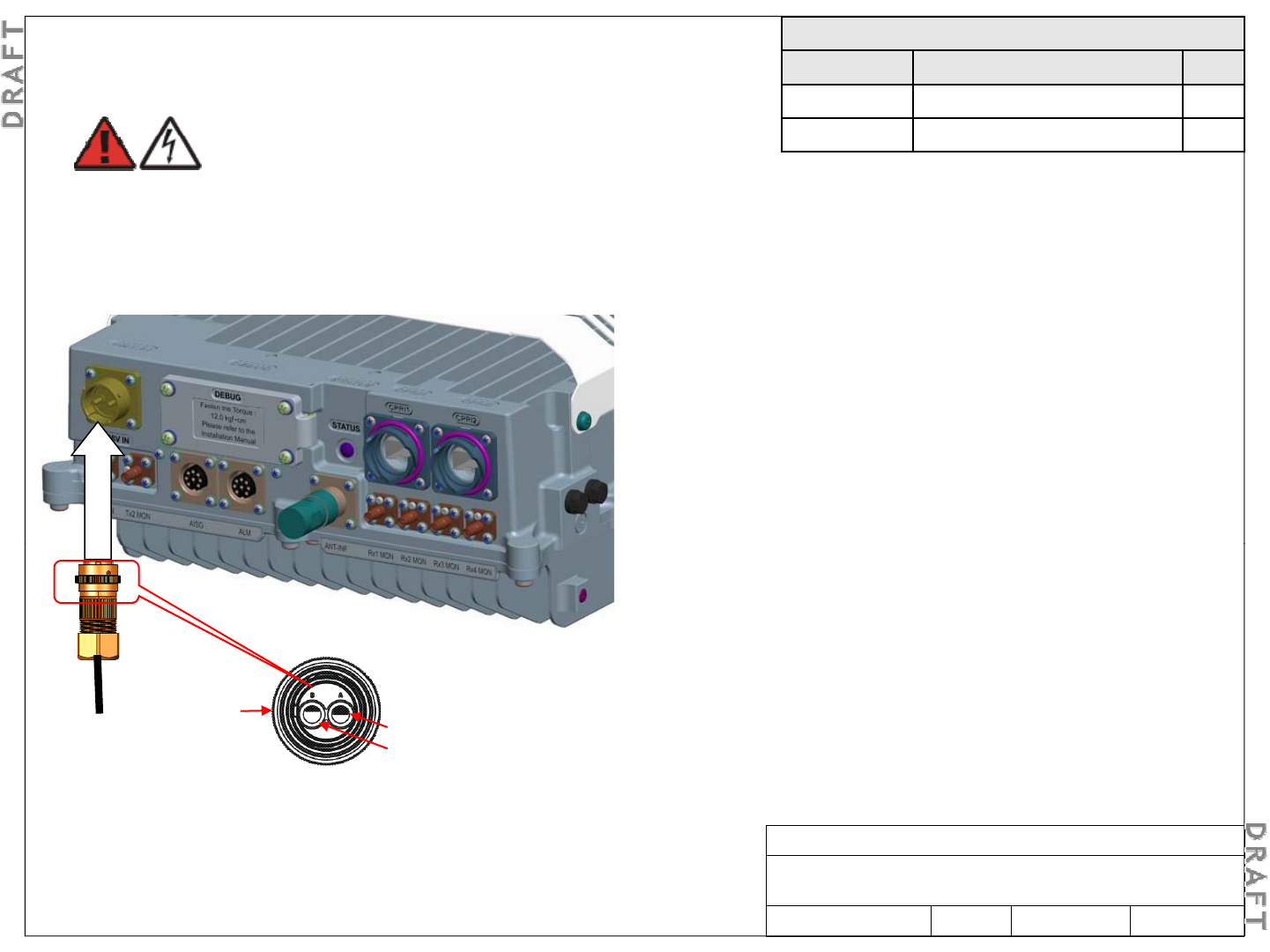
DANGER
5-9. Connect DC power cable
N/A
Power cable
,
customer provided
1
Step 2
Conductors must be within an outer jacket to work with this
DC plug
Electric shock hazard
Contact with energized network element power supply
lines can result in serious personal injury.
Ensure that the DC power is OFF and secured against
DC plug
Step 3
Cut the DC power cable to an appropriate length and strip
the ends of the wires.
St 4
turn-on before completing this procedure.
St
ep
4
Using the assembly instructions provided with the DC power
plug, attach the DC power cable to the DC power plug as
follows :
•Pin A to -48V
-48V DC
•Pin B to 0V (-48V return)
Step 5
Plug the DC power cable into the -48 V DC IN port and hand
tighten the o ter connector shell to sec re the cable
tighten the o
u
ter connector shell to sec
u
re the cable
.
S 1
Rear view of
DC power
plug body A = -48V
B = 0V
Alcatel-Lucent RRH 2x60-B4
Alcatel-Lucent – Internal
Proprietary – Use pursuant to Company instruction
3MN-01520-0002-RJZZA Issue 0.02 March 2014 Sheet 22 of 24
S
tep
1
If not previously installed, route the customer provided
DC power cable to the bottom of the RRH.
5-10. Final checks of installation
Ste
p
1
p
Inspect site for loose tools, materials, and parts. Remove all such loose tools, materials, and parts.
Step 2
Verify that all the exterior mounting hardware and cable connections are secure.
Step 3
Check the overall appearance of the Alcatel-Lucent RRH2x60-B4.
Note: Verify that nothing is unbalanced, unsecured, or out of alignment and no unintended mechanical
alteration of the Alcatel-Lucent RRH2x60-B4, mounting brackets, or support structure has occurred.
Ste
p
4
p
Fill the site install checklist to be delivered to the integration team.
6. Product conformance statements
For the product conformance statements that apply to the Alcatel-Lucent RRH2x60-B4, see Alcatel-Lucent Remote
Radio Head 2x60-B4 – Site Preparation Guidelines, 3MN-01520-0001-RJZZA.
Alcatel-Lucent RRH 2x60-B4
Alcatel-Lucent – Internal
Proprietary – Use pursuant to Company instruction
3MN-01520-0002-RJZZA Issue 0.02 March 2014 Sheet 23 of 24
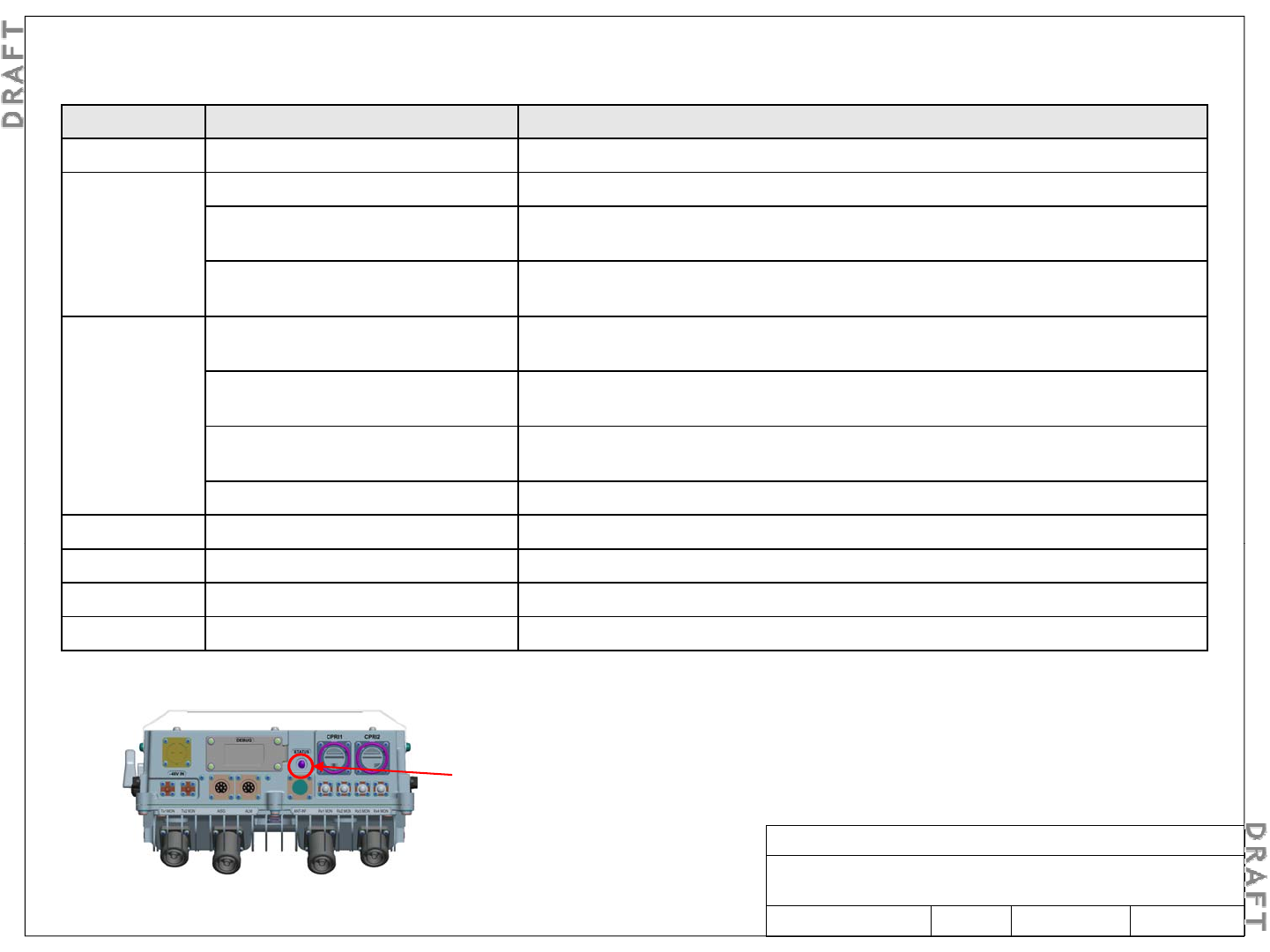
LED state Status Description
General status LED states after power up
7. Reference: General status LED states
Off No power supplied No DC power
Solid red Initial power on RRH is initializing (if just powered on or reset)
Non-recoverable critical failure A critical hardware failure prevents the transmit and/or active receive paths from
functioning
l
bl f l
lf l h h d d f l bl
Non-critica
l
non-recovera
bl
e
f
ai
l
ure Non-critica
l f
au
l
t
(ot
h
er
t
h
an
antenna)
d
etecte
d
,
f
au
l
t
is
not
recovera
bl
e, RF
transmission is still ON
Flashing red Recoverable critical failure RRH not currently operational due to hardware fault, but should recover (e.g.,
under-temperature warm up, over-temperature critical shutdown)
External power supply failure A recoverable fault is detected and the external connections (power, antenna)
should be checked
should be checked
Non-critical recoverable failure Non-critical fault (other than antenna) detected, fault is recoverable, RF
transmission is still ON
External antenna failure An equipped antenna has a VSWR fault
Flashing yellow Software download RRH is downloading software and RF transmission is OFF, but is currently operational
Solid yellow Slave CPRI link failure The slave CPRI link (CPRI-1) has failed
Solid green Normal operation No critical failures or faults, transmitter is enabled.
Flashing green Standby No critical failures or faults, but the transmitter is disabled
Bottom view
Bottom view
Status LED
Alcatel-Lucent RRH 2x60-B4
Alcatel-Lucent – Internal
Proprietary – Use pursuant to Company instruction
3MN-01520-0002-RJZZA Issue 0.02 March 2014 Sheet 24 of 24