KMW INTNODEHPV03 Zigbee Module User Manual
KMW INC. Zigbee Module
UserManual.wiki
>
KMW
>
INTNODEHPV03 User Manual
User Manual
Navigation menu
Upload a User Manual
Namespaces
Wiki Guide
HTML
PDF
Info
Views
User Manual
Discussion / Help
Navigation
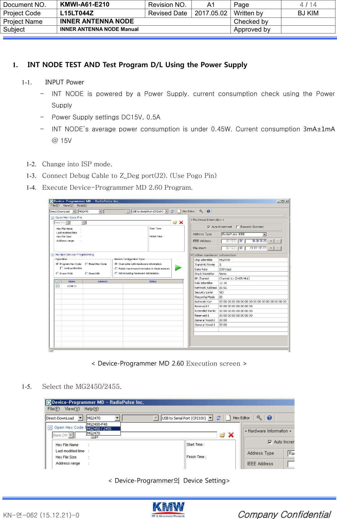
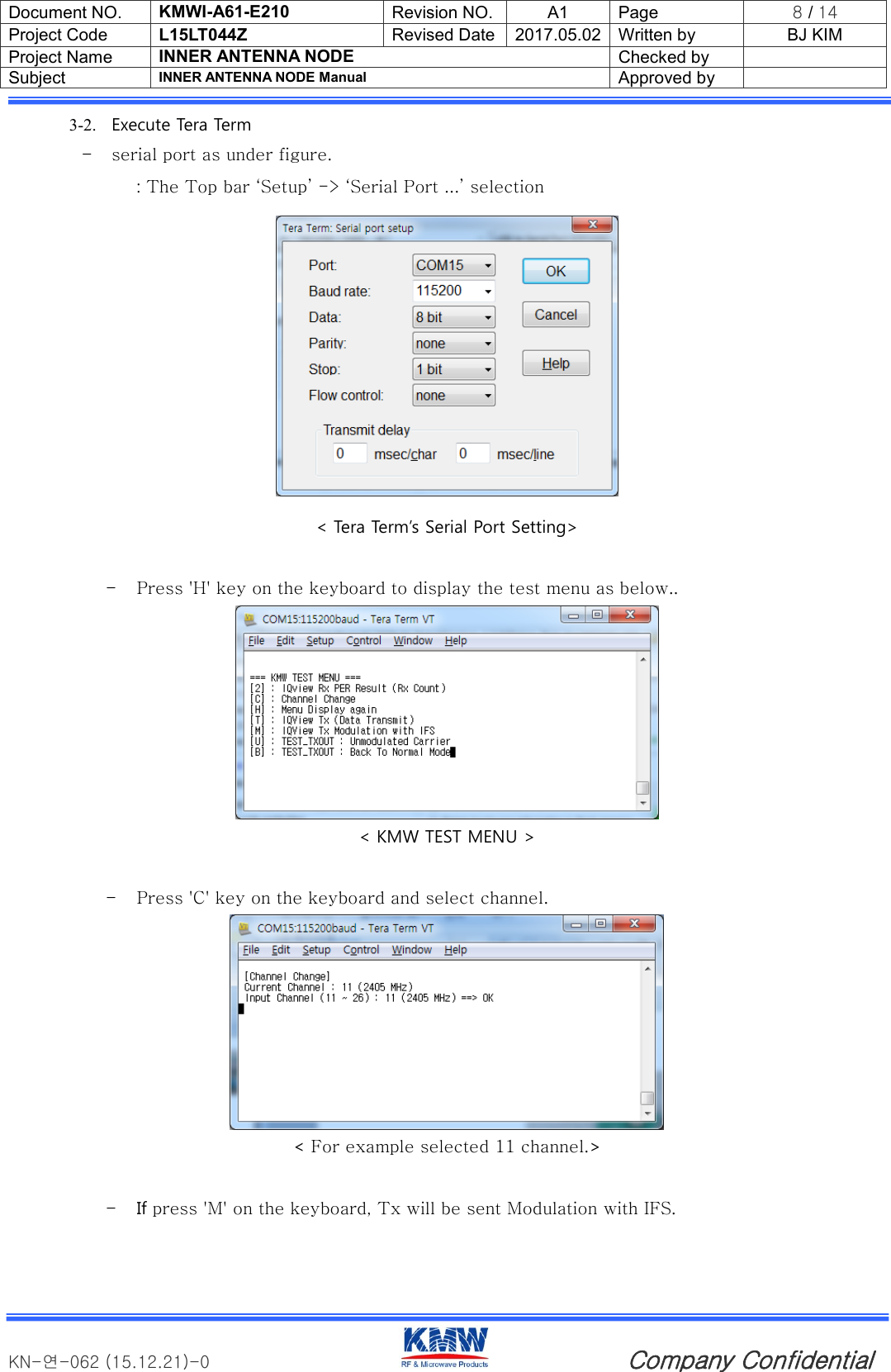
![Document NO. KMWI-A61-E210 Revision NO. A1 Page 6 / 14 Project Code L15LT044Z Revised Date 2017.05.02 Written by BJ KIM Project Name INNER ANTENNA NODE Checked by Subject INNER ANTENNA NODE Manual Approved by KN-연-062 (15.12.21)-0 Company Confidential 2. IQ NxN Test Setting Setting test environment as under figure IQ nxnTEM CELL PCUSB LAN PORTRF1RF2LAN PORTUSBRF IN/OUTRF CABLELAN CABLEUSB CABLE[] < Test environment image> 2-1. Connect Ethernet cable to Ethernet socket at IQ NXN device rear. Then Check communication to PC to IQ NXN < IQ NXN rear > Block Diagram](https://usermanual.wiki/KMW/INTNODEHPV03/User-Guide-3402641-Page-6.png)
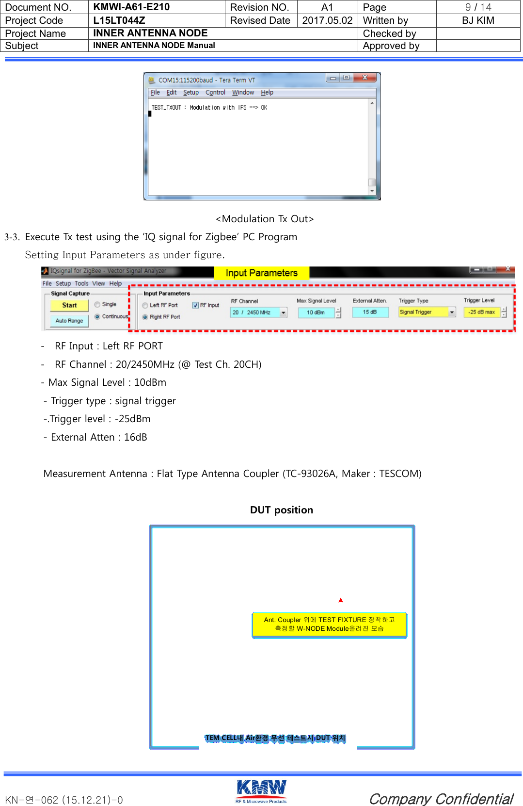
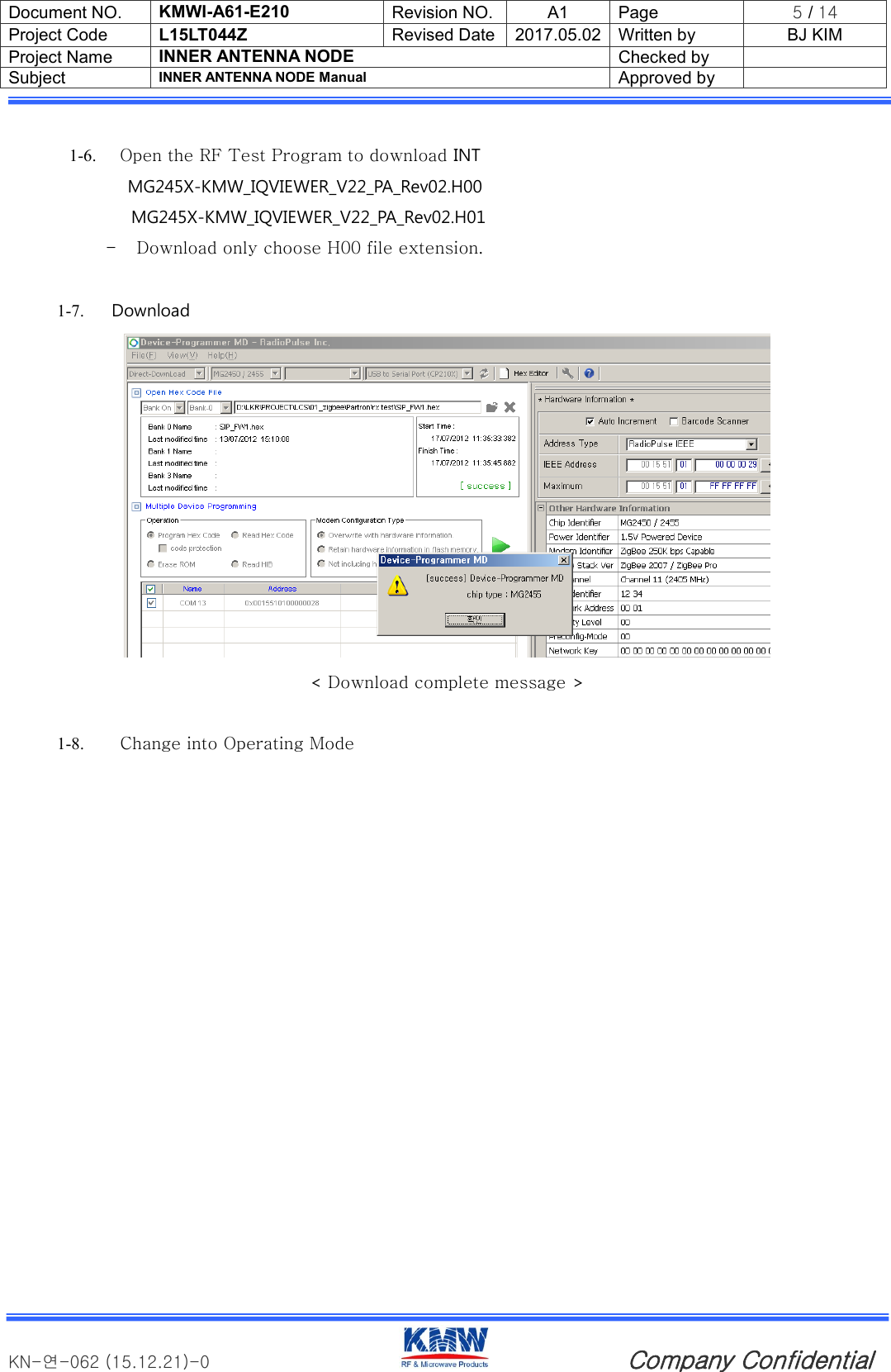
![Document NO. KMWI-A61-E210 Revision NO. A1 Page 10 / 14 Project Code L15LT044Z Revised Date 2017.05.02 Written by BJ KIM Project Name INNER ANTENNA NODE Checked by Subject INNER ANTENNA NODE Manual Approved by KN-연-062 (15.12.21)-0 Company Confidential < Tx test measure > - Compare with the following items to check for defects < Zigbee Rx Test ChecK List> - RX Test 4-1. Execute 'vector signal analyzer' as under figure. < Execute Vector signal analyzer > Items Req'd Spec Remark Transmit Power (Peak Power) ≥5dBm [6.9.5]IEEE802.15.4-2006 Spectrum PSD mask Check [6.5.3.1]IEEE802.15.4-2006 Transmit Center Frequency Tolerance ±40ppm [6.9.4]IEEE802.15.4-2006 Error Vector Magnitude ≤35% [6.9.3]IEEE802.15.4-2006](https://usermanual.wiki/KMW/INTNODEHPV03/User-Guide-3402641-Page-10.png)
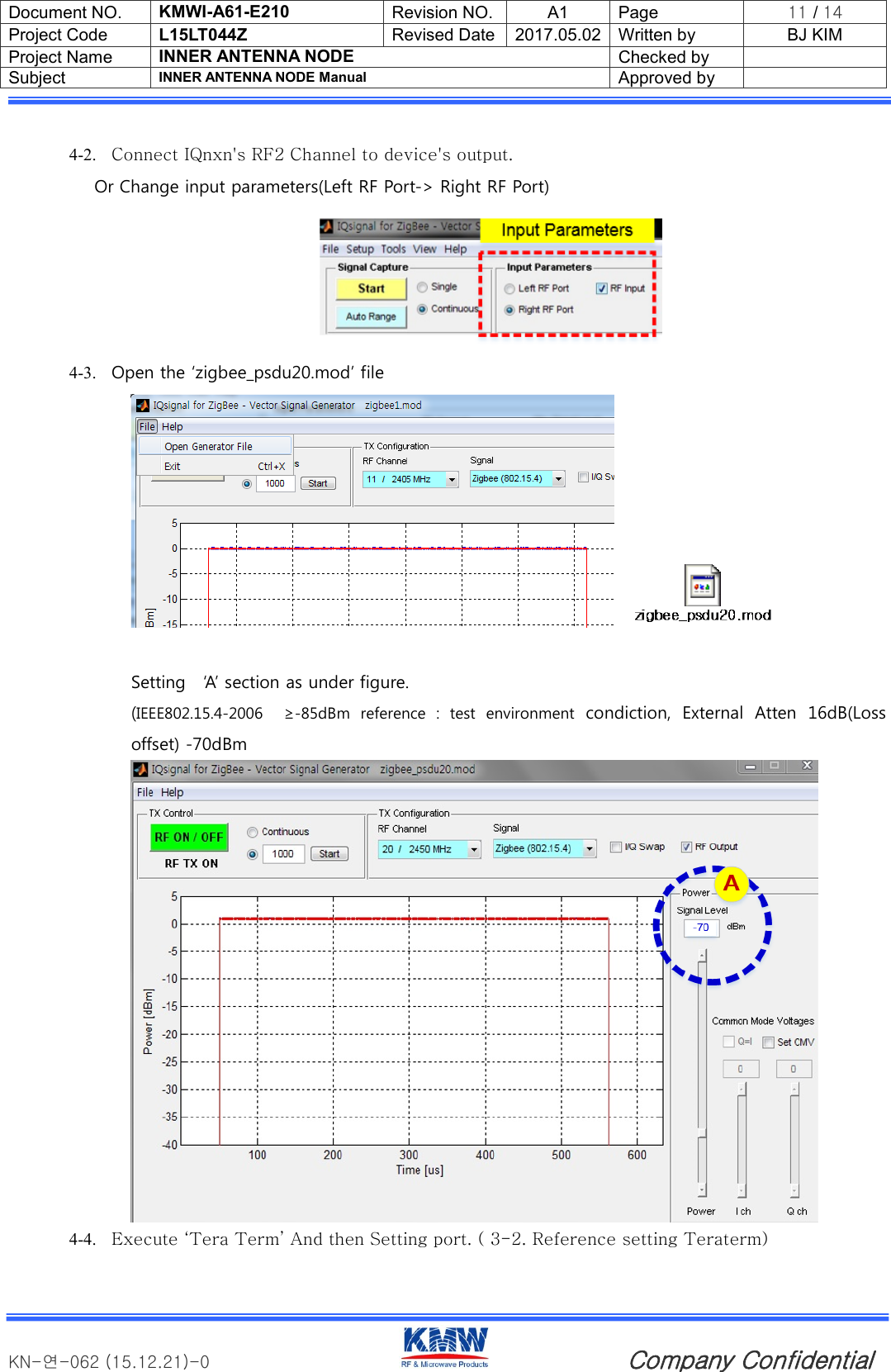
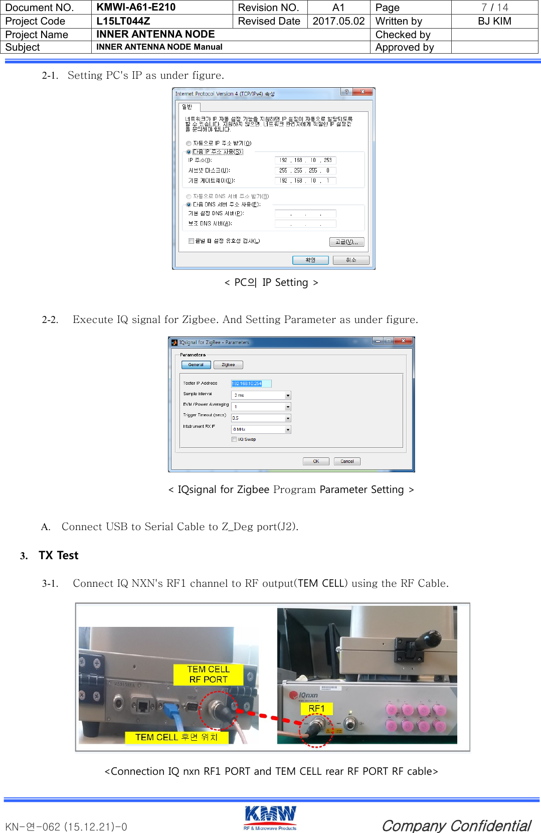
![Document NO. KMWI-A61-E210 Revision NO. A1 Page 12 / 14 Project Code L15LT044Z Revised Date 2017.05.02 Written by BJ KIM Project Name INNER ANTENNA NODE Checked by Subject INNER ANTENNA NODE Manual Approved by KN-연-062 (15.12.21)-0 Company Confidential 4-5. Select RF ON/OFF button as under figure, select 'Start' button. then number 1000's Tx data is transmitted to the INT NODE Board.. <RF ON/OFF, Start Button> 4-2. If press '2' on the keyboard, can be check transmitted result. < Tera Term Rx count Output Screen > - Compare with the following items to check for defects Items Req'd Spec Remark Receiver Sensitivity ≥-70dBm [6.5.3.3]IEEE802.15.4-2006 (≥-85dBm) Packet Error Rate(1000) ≤1% [6.5.3.3]IEEE802.15.4-2006 Receiver maximum input level -20dBm [6.9.6]IEEE802.15.4-2006 <I IEEE802.15.4 standardize Zigbee Rx Test Check List > Specified as ≥-85dBm on IEEE802.15.4-2006, Changed to ≥-75dBm considering that the test environment is wireless.](https://usermanual.wiki/KMW/INTNODEHPV03/User-Guide-3402641-Page-12.png)