User Manual
Document NO.
KMWI-A61-E210
Revision NO.
A1
Page
1 / 14
Project Code
L15LT044Z
Revised Date
2017.05.02
Written by
BJ KIM
Project Name
INNER ANTENNA NODE
Checked by
Subject
INNER ANTENNA NODE Manual
Approved by
KN-연-062 (15.12.21)-0
Company Confidential
2017. 05. 02.
INNER ANTENNA NODE
Test Manual

Document NO.
KMWI-A61-E210
Revision NO.
A1
Page
2 / 14
Project Code
L15LT044Z
Revised Date
2017.05.02
Written by
BJ KIM
Project Name
INNER ANTENNA NODE
Checked by
Subject
INNER ANTENNA NODE Manual
Approved by
KN-연-062 (15.12.21)-0
Company Confidential
Document Revision History
No
Description
Author
Page
REV. NO
Revised
Date
1
-. initial
BJ KIM
A0
2017. 05. 02

Document NO.
KMWI-A61-E210
Revision NO.
A1
Page
3 / 14
Project Code
L15LT044Z
Revised Date
2017.05.02
Written by
BJ KIM
Project Name
INNER ANTENNA NODE
Checked by
Subject
INNER ANTENNA NODE Manual
Approved by
KN-연-062 (15.12.21)-0
Company Confidential
INDEX
DOCUMENT REVISION HISTORY ........................................................................................................................ 2
1. INT NODE TEST AND TEST PROGRAM D/L USING THE POWER SUPPLY 오류! 책갈피가 정의되어 있
지 않습니다.
2. IQ NXN SETTING .................................................................................................................................................. 6
3. TX TEST ................................................................................................................................................................. 7
4. RX TEST ................................................................................................................................................................ 10
Document NO.
KMWI-A61-E210
Revision NO.
A1
Page
4 / 14
Project Code
L15LT044Z
Revised Date
2017.05.02
Written by
BJ KIM
Project Name
INNER ANTENNA NODE
Checked by
Subject
INNER ANTENNA NODE Manual
Approved by
KN-연-062 (15.12.21)-0
Company Confidential
1. INT NODE TEST AND Test Program D/L Using the Power Supply
1-1. INPUT Power
- INT NODE is powered by a Power Supply. current consumption check using the Power
Supply
- Power Supply settings DC15V, 0.5A
- INT NODE’s average power consumption is under 0.45W. Current consumption 3mA±1mA
@ 15V
1-2. Change into ISP mode.
1-3. Connect Debug Cable to Z_Deg port(J2). (Use Pogo Pin)
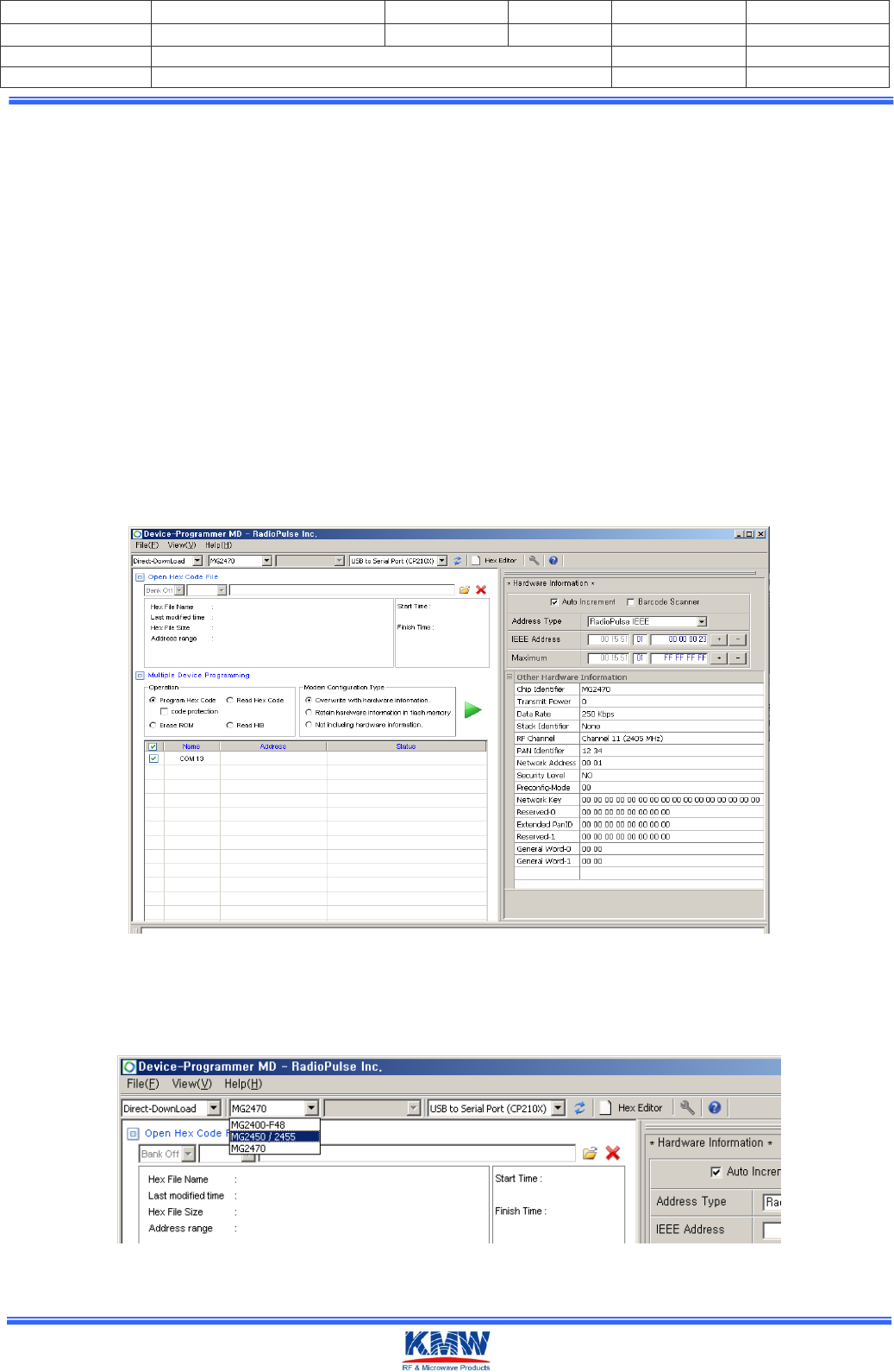
1-4. Execute Device-Programmer MD 2.60 Program.
< Device-Programmer MD 2.60 Execution screen >
1-5. Select the MG2450/2455.
< Device-Programmer의 Device Setting>
Document NO.
KMWI-A61-E210
Revision NO.
A1
Page
5 / 14
Project Code
L15LT044Z
Revised Date
2017.05.02
Written by
BJ KIM
Project Name
INNER ANTENNA NODE
Checked by
Subject
INNER ANTENNA NODE Manual
Approved by
KN-연-062 (15.12.21)-0
Company Confidential
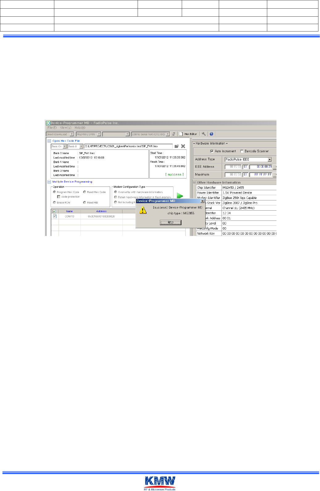
1-6. Open the RF Test Program to download INT
MG245X-KMW_IQVIEWER_V22_PA_Rev02.H00
MG245X-KMW_IQVIEWER_V22_PA_Rev02.H01
- Download only choose H00 file extension.
1-7. Download
< Download complete message >
1-8. Change into Operating Mode
Document NO.
KMWI-A61-E210
Revision NO.
A1
Page
6 / 14
Project Code
L15LT044Z
Revised Date
2017.05.02
Written by
BJ KIM
Project Name
INNER ANTENNA NODE
Checked by
Subject
INNER ANTENNA NODE Manual
Approved by
KN-연-062 (15.12.21)-0
Company Confidential
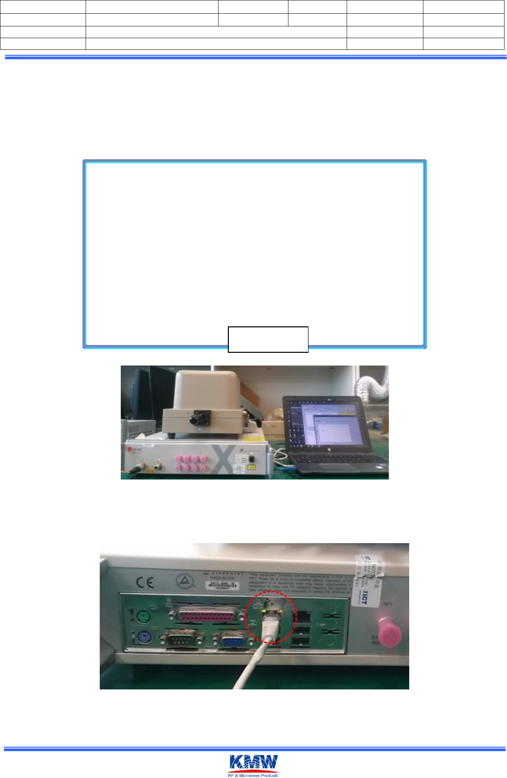
2. IQ NxN Test Setting
Setting test environment as under figure
IQ nxn
TEM CELL PC
USB LAN PORT
RF1RF2
LAN PORT
USB
RF
IN/OUT
RF CABLE
LAN CABLE
USB CABLE
[]
< Test environment image>
2-1. Connect Ethernet cable to Ethernet socket at IQ NXN device rear. Then Check
communication to PC to IQ NXN
< IQ NXN rear >
Block Diagram
Document NO.
KMWI-A61-E210
Revision NO.
A1
Page
7 / 14
Project Code
L15LT044Z
Revised Date
2017.05.02
Written by
BJ KIM
Project Name
INNER ANTENNA NODE
Checked by
Subject
INNER ANTENNA NODE Manual
Approved by
KN-연-062 (15.12.21)-0
Company Confidential
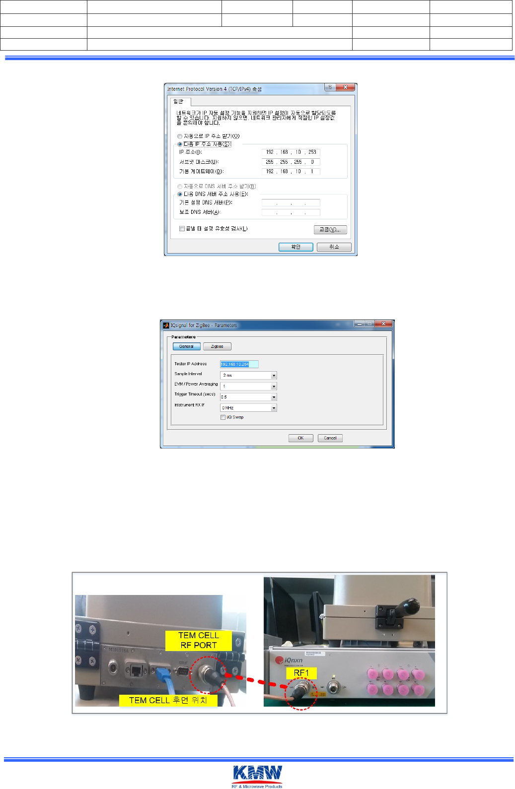
2-1. Setting PC's IP as under figure.
< PC의 IP Setting >
2-2. Execute IQ signal for Zigbee. And Setting Parameter as under figure.
< IQsignal for Zigbee Program Parameter Setting >
A. Connect USB to Serial Cable to Z_Deg port(J2).
3. TX Test
3-1. Connect IQ NXN's RF1 channel to RF output(TEM CELL) using the RF Cable.
<Connection IQ nxn RF1 PORT and TEM CELL rear RF PORT RF cable>
Document NO.
KMWI-A61-E210
Revision NO.
A1
Page
8 / 14
Project Code
L15LT044Z
Revised Date
2017.05.02
Written by
BJ KIM
Project Name
INNER ANTENNA NODE
Checked by
Subject
INNER ANTENNA NODE Manual
Approved by
KN-연-062 (15.12.21)-0
Company Confidential
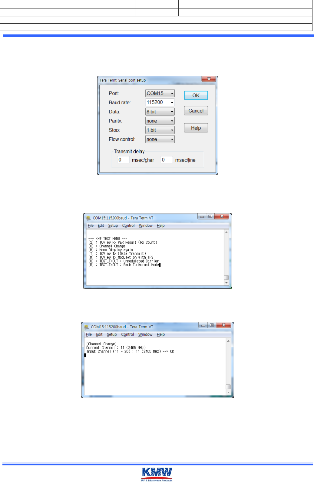
3-2. Execute Tera Term
- serial port as under figure.
: The Top bar ‘Setup’ -> ‘Serial Port ...’ selection
< Tera Term’s Serial Port Setting>
- Press 'H' key on the keyboard to display the test menu as below..
< KMW TEST MENU >
- Press 'C' key on the keyboard and select channel.
< For example selected 11 channel.>
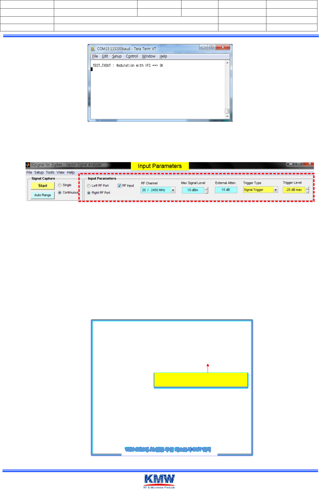
- If press 'M' on the keyboard, Tx will be sent Modulation with IFS.
Document NO.
KMWI-A61-E210
Revision NO.
A1
Page
9 / 14
Project Code
L15LT044Z
Revised Date
2017.05.02
Written by
BJ KIM
Project Name
INNER ANTENNA NODE
Checked by
Subject
INNER ANTENNA NODE Manual
Approved by
KN-연-062 (15.12.21)-0
Company Confidential
<Modulation Tx Out>
3-3. Execute Tx test using the ‘IQ signal for Zigbee’ PC Program
Setting Input Parameters as under figure.
- RF Input : Left RF PORT
- RF Channel : 20/2450MHz (@ Test Ch. 20CH)
- Max Signal Level : 10dBm
- Trigger type : signal trigger
-.Trigger level : -25dBm
- External Atten : 16dB
Measurement Antenna : Flat Type Antenna Coupler (TC-93026A, Maker : TESCOM)
DUT position
Antenna Coupler TEST FIXTURE
Whistle NODE Module Case와 Ant Coupler 이격 거리
< 1.0mm
Ant. Coupler 위에 TEST FIXTURE 장착하고
측정할 W-NODE Module올려진 모습
TEM CELLAirDUT
Document NO.
KMWI-A61-E210
Revision NO.
A1
Page
10 / 14
Project Code
L15LT044Z
Revised Date
2017.05.02
Written by
BJ KIM
Project Name
INNER ANTENNA NODE
Checked by
Subject
INNER ANTENNA NODE Manual
Approved by
KN-연-062 (15.12.21)-0
Company Confidential
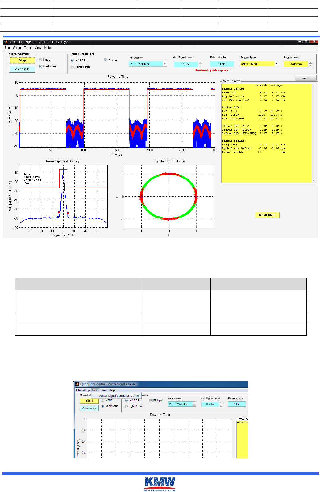
< Tx test measure >
- Compare with the following items to check for defects
< Zigbee Rx Test ChecK List>
- RX Test
4-1. Execute 'vector signal analyzer' as under figure.
< Execute Vector signal analyzer >
Items
Req'd Spec
Remark
Transmit Power (Peak Power)
≥5dBm
[6.9.5]IEEE802.15.4-2006
Spectrum PSD mask
Check
[6.5.3.1]IEEE802.15.4-2006
Transmit Center Frequency Tolerance
±40ppm
[6.9.4]IEEE802.15.4-2006
Error Vector Magnitude
≤35%
[6.9.3]IEEE802.15.4-2006
Document NO.
KMWI-A61-E210
Revision NO.
A1
Page
11 / 14
Project Code
L15LT044Z
Revised Date
2017.05.02
Written by
BJ KIM
Project Name
INNER ANTENNA NODE
Checked by
Subject
INNER ANTENNA NODE Manual
Approved by
KN-연-062 (15.12.21)-0
Company Confidential
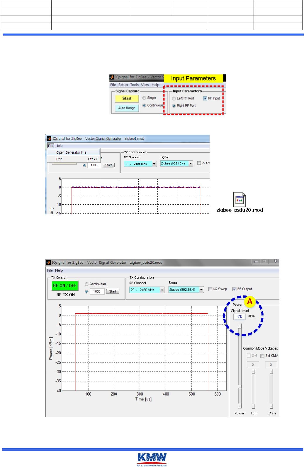
4-2. Connect IQnxn's RF2 Channel to device's output.
Or Change input parameters(Left RF Port-> Right RF Port)
4-3. Open the ‘zigbee_psdu20.mod’ file
Setting ‘A’ section as under figure.
(IEEE802.15.4-2006 ≥-85dBm reference : test environment condiction, External Atten 16dB(Loss
offset) -70dBm
4-4. Execute ‘Tera Term’ And then Setting port. ( 3-2. Reference setting Teraterm)
Document NO.
KMWI-A61-E210
Revision NO.
A1
Page
12 / 14
Project Code
L15LT044Z
Revised Date
2017.05.02
Written by
BJ KIM
Project Name
INNER ANTENNA NODE
Checked by
Subject
INNER ANTENNA NODE Manual
Approved by
KN-연-062 (15.12.21)-0
Company Confidential
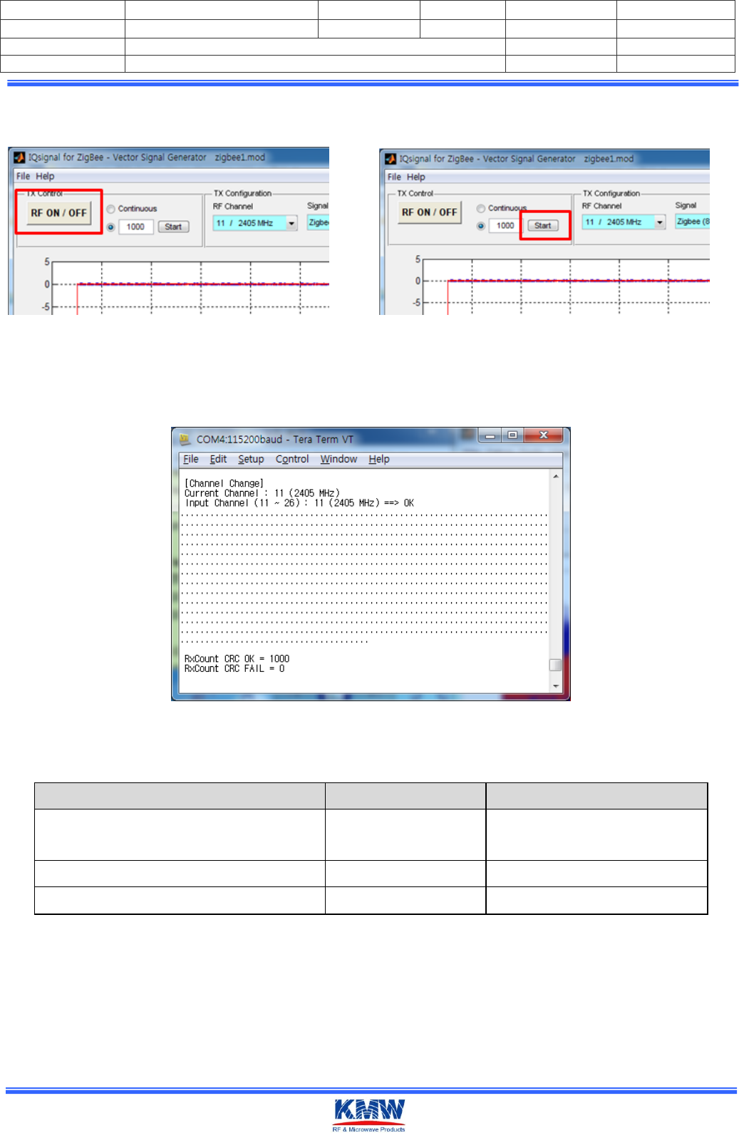
4-5. Select RF ON/OFF button as under figure, select 'Start' button. then number 1000's Tx data
is transmitted to the INT NODE Board..
<RF ON/OFF, Start Button>
4-2. If press '2' on the keyboard, can be check transmitted result.
< Tera Term Rx count Output Screen >
- Compare with the following items to check for defects
Items
Req'd Spec
Remark
Receiver Sensitivity
≥-70dBm
[6.5.3.3]IEEE802.15.4-2006
(≥-85dBm)
Packet Error Rate(1000)
≤1%
[6.5.3.3]IEEE802.15.4-2006
Receiver maximum input level
-20dBm
[6.9.6]IEEE802.15.4-2006
<I IEEE802.15.4 standardize Zigbee Rx Test Check List >
Specified as ≥-85dBm on IEEE802.15.4-2006, Changed to ≥-75dBm considering that the test environment is
wireless.

Document NO.
KMWI-A61-E210
Revision NO.
A1
Page
13 / 14
Project Code
L15LT044Z
Revised Date
2017.05.02
Written by
BJ KIM
Project Name
INNER ANTENNA NODE
Checked by
Subject
INNER ANTENNA NODE Manual
Approved by
KN-연-062 (15.12.21)-0
Company Confidential
FCC compliance Information
FCC Information to User
This equipment has been tested and found to comply with the limits for a Class B digital device, pursuant to
Part 15 of the FCC Rules. These limits are designed to provide reasonable protection against harmful
interference in a residential installation. This equipment generates, uses and can radiate radio frequency
energy and, if not installed and used in accordance with the instructions, may cause harmful interference to
radio communications. However, there is no guarantee that interference will not occur in a particular
installation. If this equipment does cause harmful interference to radio or television reception, which can be
determined by turning the equipment off and on, the user is encouraged to try to correct the interference by
one of the following measures:
• Reorient or relocate the receiving antenna.
• Increase the separation between the equipment and receiver.
• Connect the equipment into an outlet on a circuit different from that to which the receiver is connected.
• Consult the dealer or an experienced radio/TV technician for help.
Caution
Modifications not expressly approved by the party responsible for compliance could void the user’s authority
to operate the equipment.
FCC Compliance Information : This device complies with Part 15 of the FCC Rules. Operation is subject to
the following two conditions: (1) This device may not cause harmful interference, and (2) this device must
accept any interference received, including interference that may cause undesired operation
Including interference that may cause undesired operation. Modifications not expressly approved by the
manufacturer could void the user’s authority To operated the equipment under FCC rules. To satisfy FCC
exterior labeling requirements, the following text must be placed on the exterior of the end product.
Contains Transmitter Module FCC ID : ORIINTNODEHPV03
CAUTION : This device and its antenna(s) must not be co-located or operated in conjunction with any other
antenna or transmitter. End users cannot modify this transmitter device. Any unauthorized modification could
void the user’s authority to operate this device.
This module is limited to installation in fixed applications, and only installed Lighting Fixture. This module can
not be attached to other device without Lighting device.
IMPORTANT NOTE:
FCC RF Radiation Exposure Statement:
This equipment complies with FCC RF radiation exposure limits set forth for an uncontrolled environment.
This equipment should be installed and operated with a minimum distance of 20 centimeters between the
radiator and your body.This transmitter must not be co-located or operating in conjunction with any other
antenna or transmitter.

Document NO.
KMWI-A61-E210
Revision NO.
A1
Page
14 / 14
Project Code
L15LT044Z
Revised Date
2017.05.02
Written by
BJ KIM
Project Name
INNER ANTENNA NODE
Checked by
Subject
INNER ANTENNA NODE Manual
Approved by
KN-연-062 (15.12.21)-0
Company Confidential
This device is intended only for OEM integrators under the following conditions:
1)The transmitter module may not be co-located with any other transmitter or antenna,
2)OEM shall not supply any tool or info to the end-user regarding to Regulatory Domain change.
As long as 2 conditions above are met, further transmitter test will not be required. However, the OEM
integrator is still responsible for testing their end-product for any additional compliance requirements
required with this module installed (for example, digital device emissions, PC peripheral requirements, etc.).
IMPORTANT NOTE: In the event that these conditions can not be met (for example certain laptop
configurations or co-location with another transmitter), then the FCC authorization is no longer considered
valid and the FCC ID can not be used on the final product. In these circumstances, the OEM integrator will
be responsible for re-evaluating the end product (including the transmitter) and obtaining a separate FCC
authorization.
Manual Information To the End User The OEM integrator has to be aware not to provide information to the
end user regarding how to install or remove this RF module in the user’s manual of the end product which
integrates this module. The end user manual shall include all required regulatory information/warning as
show in this manual.