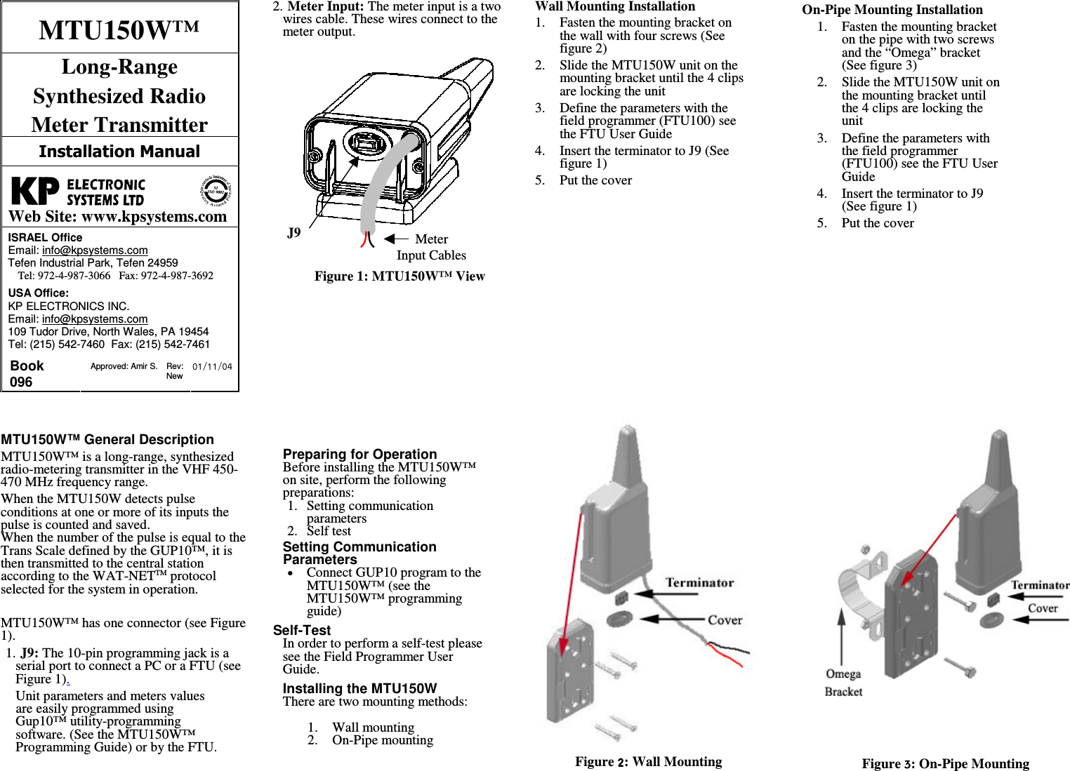
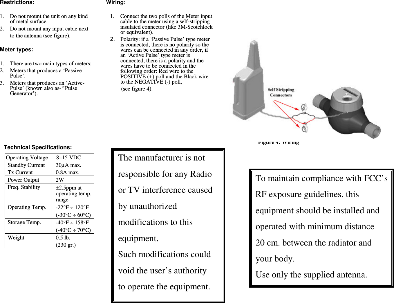
KP Electronic Systems KPMTU150W UHF DATA TRANSMITTER User Manual users manual

KP Electronic Systems Ltd UHF DATA TRANSMITTER users manual

users manual

J9Meter Input CablesMTU150W™ Long-Range  Synthesized Radio  Meter Transmitter   Web Site: www.kpsystems.comISRAEL Office  Email: info@kpsystems.com Tefen Industrial Park, Tefen 24959 Tel: 972-4-987-3066   Fax: 972-4-987-3692 USA Office:  KP ELECTRONICS INC. Email: info@kpsystems.com 109 Tudor Drive, North Wales, PA 19454 Tel: (215) 542-7460  Fax: (215) 542-7461 Book 096  Approved: Amir S.  Rev: New  MTU150W™ General Description MTU150W™ is a long-range, synthesized radio-metering transmitter in the VHF 450-470 MHz frequency range. When the MTU150W detects pulse conditions at one or more of its inputs the pulse is counted and saved.  When the number of the pulse is equal to the Trans Scale defined by the GUP10™, it is then transmitted to the central station according to the WAT-NETTM protocol selected for the system in operation.  MTU150W™ has one connector (see Figure 1). 1. J9: The 10-pin programming jack is a serial port to connect a PC or a FTU (see Figure 1).  Unit parameters and meters values are easily programmed using Gup10™ utility-programming software. (See the MTU150W™ Programming Guide) or by the FTU. 2. Meter Input: The meter input is a two wires cable. These wires connect to the meter output.          Figure 1: MTU150W™ View             Preparing for Operation Before installing the MTU150W™ on site, perform the following preparations: 1.  Setting communication parameters 2.  Self test   Setting Communication Parameters Connect GUP10 program to the MTU150W™ (see the MTU150W™ programming guide)  Self-Test  In order to perform a self-test please see the Field Programmer User Guide.  Installing the MTU150W There are two mounting methods:  1.  Wall mounting 2.  On-Pipe mounting   Wall Mounting Installation 1.  Fasten the mounting bracket on the wall with four screws (See figure 2) 2.  Slide the MTU150W unit on the mounting bracket until the 4 clips are locking the unit 3.  Define the parameters with the field programmer (FTU100) see the FTU User Guide 4.  Insert the terminator to J9 (See figure 1) 5.  Put the cover  On-Pipe Mounting Installation 1.  Fasten the mounting bracket on the pipe with two screws and the “Omega” bracket (See figure 3) 2.  Slide the MTU150W unit on the mounting bracket until the 4 clips are locking the unit 3.  Define the parameters with the field programmer (FTU100) see the FTU User Guide 4.  Insert the terminator to J9 (See figure 1) 5.  Put the cover                                Figure : Wall Mounting   Figure : On-Pipe Mounting
Restrictions:  1.  Do not mount the unit on any kind of metal surface. 2.  Do not mount any input cable next  to the antenna (see figure).  Meter types:  1.There are two main types of meters: 2.  Meters that produces a ‘Passive Pulse’. 3.  Meters that produces an ‘Active-Pulse’ (known also as-‘’Pulse Generator’).        Technical Specifications:   Operating Voltage 8–15 VDC Standby Current  30µA max. Tx Current  0.8A max. Power Output  2W Freq. Stability  2.5ppm at operating temp. range Operating Temp.  -22F  120F (-30C  60C) Storage Temp.  -40F  158F (-40C  70C) Weight  0.5 lb. (230 gr.) Wiring:  1.  Connect the two polls of the Meter input cable to the meter using a self-stripping insulated connector (like 3M-Scotchlock or equivalent).   2.  Polarity: if a ‘Passive Pulse’ type meter is connected, there is no polarity so the wires can be connected in any order, if an ‘Active Pulse’ type meter is connected, there is a polarity and the wires have to be connected in the following order: Red wire to the POSITIVE (+) poll and the Black wire to the NEGATIVE (-) poll,    (see figure 4).      The manufacturer is not responsible for any Radio or TV interference caused by unauthorized modifications to this equipment. Such modifications could void the user’s authority to operate the equipment. Figure 4: Wiring   To maintain compliance with FCC’s RF exposure guidelines, this equipment should be installed and operated with minimum distance  20 cm. between the radiator and your body. Use only the supplied antenna.

Navigation menu