Kelvin Hughes DTX-A3-FDLR X BAND RADAR User Manual
Kelvin Hughes Limited X BAND RADAR
User Manual

UDU.;11!Ujqtg!Dcugf!Tcfct!
U{uvgou!
Qrgtcvqt!cpf!Ockpvgpcpeg!!
Jcpfdqqm!
!
!
!
!
!
!
!
!
!
!
!
MJ
.
2713
.
3
!kuuwg!2
!
UKVWCVKQPCN!KPVGNNKIGPEG-!VJG!YQTNF!QXGT!

SBS-900 Shore Based Radar Systems
Chapter 1: Contents
KH-1602-2 issue 1: Standard SBS900 Systems Operator & Maintenance Handbook
Page 2 of 240
Page intentionally blank

SBS-900 Shore Based Radar Systems
Chapter 1: Contents
KH-1602-2 issue 1: Standard SBS900 Systems Operator & Maintenance Handbook
Page 3 of 240
1 Contents
1 Contents..................................................................................................................................... 3
2 Health & Safety warnings .........................................................................................................7
2.1 Hazards .......................................................................................................................................................................7
2.2 Antenna rotation warning .............................................................................................................................................7
2.3 Radiation hazards........................................................................................................................................................8
2.4 Microwave radiation levels ...........................................................................................................................................8
2.5 Working aloft................................................................................................................................................................9
2.6 Man aloft switch/ antenna isolation...............................................................................................................................9
2.7 Anti-static handling.....................................................................................................................................................10
2.8 RoHS statement.........................................................................................................................................................10
2.9 End of life disposal.....................................................................................................................................................10
2.10 AC supplies...........................................................................................................................................................11
2.11 Grounding/ earth points.........................................................................................................................................12
3 Software licensing and virus protection...............................................................................13
3.1 Software.....................................................................................................................................................................13
3.2 Virus precautions .......................................................................................................................................................13
4 Handbooks...............................................................................................................................15
5 Technical overview .................................................................................................................17
5.1 Generic system..........................................................................................................................................................17
5.2 SBS-900 overview......................................................................................................................................................18
5.3 SBS-900-1 .................................................................................................................................................................20
5.4 SBS-900-2 .................................................................................................................................................................21
5.5 SBS-900-3 .................................................................................................................................................................22
5.6 SBS-900-4 .................................................................................................................................................................23
5.7 SBS-900-51 ...............................................................................................................................................................24
5.8 Standard antenna sub system....................................................................................................................................25
5.9 Advanced antenna sub system ..................................................................................................................................26
5.10 Transceiver enclosure...........................................................................................................................................27
5.11 Radar Distribution Unit ..........................................................................................................................................30
5.12 System control ......................................................................................................................................................32
5.13 Unit identification...................................................................................................................................................33
6 Local operation instructions..................................................................................................35
6.1 Antenna rotation warnings..........................................................................................................................................35
6.2 Local control overview................................................................................................................................................36
6.3 Switch ON, OFF & Emergency stop ...........................................................................................................................41
6.4 Local control operational states..................................................................................................................................44
6.5 Switch from Local to Remote......................................................................................................................................46
6.6 Menus........................................................................................................................................................................47
7 Remote operation instructions..............................................................................................69
7.1 Remote control operator instructions..........................................................................................................................69
7.2 External commands ...................................................................................................................................................69
7.3 Remote control operational states..............................................................................................................................70

SBS-900 Shore Based Radar Systems
Chapter 1: Contents
KH-1602-2 issue 1: Standard SBS900 Systems Operator & Maintenance Handbook
Page 4 of 240
8 Service display/ RadarView control ......................................................................................73
8.1 Overview....................................................................................................................................................................73
8.2 SBS-A3-2 Base system..............................................................................................................................................73
8.3 SBS-A3-3 Single transceiver......................................................................................................................................74
8.4 SBS-A3-4 dual transceiver.........................................................................................................................................74
8.5 SBS-A3-5 ASTERIX control .......................................................................................................................................75
8.6 Keyboard, monitor & Mouse.......................................................................................................................................75
8.7 Service Display PC overview......................................................................................................................................76
8.8 Switching ON/ OFF ....................................................................................................................................................77
8.9 Emergency Stop.........................................................................................................................................................78
8.10 RadarView operator overview................................................................................................................................80
9 Planned maintenance .............................................................................................................85
9.1 Standard Antenna Systems........................................................................................................................................85
9.2 Advanced Antenna Systems ......................................................................................................................................86
9.3 System isolation.........................................................................................................................................................87
9.4 Annual maintenance procedure..................................................................................................................................88
9.5 3-year maintenance ...................................................................................................................................................98
9.6 5-year maintenance three-phase inverter.................................................................................................................100
9.7 10-year maintenance: VF-S15..................................................................................................................................114
9.8 Earth bonding maintenance......................................................................................................................................120
10 Corrective maintenance .......................................................................................................121
10.1 General precautions............................................................................................................................................121
10.2 Standard systems overview.................................................................................................................................122
10.3 Standard X-band.................................................................................................................................................128
10.4 Standard dual X & S-band...................................................................................................................................134
10.5 Standard S-band.................................................................................................................................................135
10.6 Advanced antenna sub systems..........................................................................................................................141
10.7 Transceiver enclosure.........................................................................................................................................142
10.8 SBS-A1-1 Radar Distribution Unit........................................................................................................................179
10.9 Alert messages ...................................................................................................................................................224
11 Abreviations...........................................................................................................................228
12 Contacting Kelvin Hughes ...................................................................................................230
12.1 Contact Kelvin Hughes........................................................................................................................................230
12.2 On-line service request........................................................................................................................................230
12.3 Kelvin Hughes regional offices ............................................................................................................................231
13 Annex A: RadarView software & service display control software .................................232
14 Annex B: Antenna sub system maintenance.....................................................................234
15 Index.......................................................................................................................................236

SBS-900 Shore Based Radar Systems
Chapter 1: Contents
KH-1602-2 issue 1: Standard SBS900 Systems Operator & Maintenance Handbook
Page 5 of 240
SBS-900 Shore Based Radar Systems
The Kelvin Hughes SBS-900 series is a range of X or S-band SharpEyeTM transceivers designed for
use in shore based radar applications. The SBS-900 range has been designed to enable system
integrators to provide a radar sensor or range of sensors that meets the following requirements:
Equipment Standards
SBS-900 series
Coastal Surveillance Systems or a Vessel Traffic Services system as defined
by IALA recommendations V-128
Designed to meet IEC60945 clause 4.5.1 for class B protected equipment for
both emissions and immunity
All Kelvin Hughes designed equipments are designed to meet the
requirements of IEC 60950, Safety of information technology equipment.
Kelvin Hughes designed equipments are constructed so that access to high
voltages may only be gained after having used a tool, such as a spanner or
screwdriver. Warning labels are prominently displayed both within the
equipment and on protective covers.
All Kelvin Goab_m Kn^ ^_mcah_^ _kocjg_hn cm ^_mcah_^ [h^ g[ho`[]nol_^ ni J_fpch Goab_m iqh
standards of practice being designed to meet the applicable requirements of the following directives:
Equipment Standards
CE marking
All KH designed equipments are designed and constructed to Kelvin
Goab_m iqh mn[h^[l^m i` jl[]nc]_ [h^ [l_ BD g[le_^ qb_l_ l_kocl_^+
meeting the applicable requirements of the following directive:
vRTTE Directive 1995/5/EC
Electromagnetic
Emissions
Designed to meet the requirements of unwanted emissions in the out of
band domain (ITU
-
R
-
SM.1541)
Designed to meet the requirements of spurious emissions (ITU.R.SM.329.9)
© Copyright Kelvin Hughes (2014) limited all rights reserved.
No parts of this publication may be reproduced, transmitted, transcribed, translated or stored in any
form or by any means without the written permission of Kelvin Hughes Limited.
Technical details contained in this publication are subject to change without notice.
When translated, the original English version of the document will remain the definitive document and
mbiof^ \_ l_`_ll_^ ni ch [hs mcno[ncih i` ^io\n+ ]ih`omcih il ]ih`fc]n-

SBS-900 Shore Based Radar Systems
Chapter 1: Contents
KH-1602-2 issue 1: Standard SBS900 Systems Operator & Maintenance Handbook
Page 6 of 240
Document history
Issue
number
Release date Details
1 August 2014 First release
Amendment record
When an amendment is incorporated into this handbook, the details should be recorded below. Any
equipment modifications should also be shown.
Amendment Number Date inserted
(DD-MM-YYYY) Initials Equipment Mod
number
SBS-900 Shore Based Radar Systems
Chapter 2: Health & Safety warnings
KH-1602-2 issue 1: Standard SBS900 Systems Operator & Maintenance Handbook
Page 7 of 240
2 Health & Safety warnings
When working on Kelvin Hughes equipment, operators, engineers and agents are expected to work
within the health and safety guidelines noted in the handbook, as issued by their respective employer
or as stated by site regulations, shipyard or vessel owner.
Risk assessments of a working area must be undertaken prior to commencement of any work and
must be regularly reviewed.
2.1 Hazards
ELECTRICAL HAZARDS:
Some equipment does not have safety interlocks fitted.
Lethal single and three phase AC and DC voltages may be present when units are open
and exposed.
Before accessing any internal parts, ALL power sources to the equipment must be fully
isolated; this must include the isolation of all UPS supported supplies to the system.
MAINS VOLTAGES:
All Kelvin Hughes equipment is supplied with mains input voltage set for 220v, 50/60 Hz
ac unless otherwise stated on labels attached to the equipment.
WARNING: Some equipment contains materials which may produce toxic fumes if burnt.
Beryllium warning: The SharpEyeTM X and S band transceivers mounted within
the SBS-800 series are factory sealed units which contain no field serviceable
parts. The SharpEyeTM transceivers must not be dismantled in the field as some
components within the factory sealed processor contain Beryllium which is
hazardous to health.
Class 1 laser product: There is a class 1 laser within the sealed SharpEye
transceiver processor which can represent a risk if the processor is
dismantled.
When fitted, the LAN fibre optic cable that connects to the SharpEyeTM
transceiver and the to the MISM type 5 modules within the radar distribution
unit is considered as a class 1 laser.
2.2 Antenna rotation warning
ANTENNA ROTATION SAFETY NOTICE:
When single and three-phase power is connected to the system and switched ON, the
antenna will rotate immediately regardless of the RUN command status.
Use the antenna rotation keyswitch or man aloft safety switches to stop antenna rotation
in an emergency.
Q_`_l ni nb_ g[chn_h[h]_ m_]ncih i` nb_ ij_l[nilm b[h^\iie `il ^_n[cfm ih mnijjcha nb_
antenna and isolating a system.
SBS-900 Shore Based Radar Systems
Chapter 2: Health & Safety warnings
KH-1602-2 issue 1: Standard SBS900 Systems Operator & Maintenance Handbook
Page 8 of 240
2.3 Radiation hazards
Radiation hazard: non-ionising
Avoid exposure to the main beam of a stationary radar antenna.
Avoid standing closer than 2 metres from the central front face of the antenna.
Users of cardiac pacemakers should be aware of the possibility that radio frequency
transmissions can damage some devices or cause irregularities in their operation.
Anyone using such devices should understand the risks present before exposure.
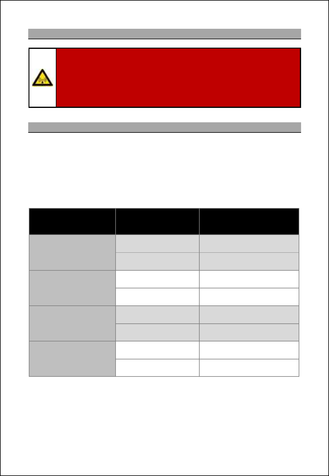
2.4 Microwave radiation levels
The Council of the European Union Recommendation 1999/519/EC (Annex III table 2) specifies the
maximum RF non-ionising field strength (power density) safe range for human exposure averaged
over a six minute period as 10W/m2in a frequency band of 10 to 300GHz.
Calculations for all SBS-900 systems show that the rotating antenna safe distance is within the
antenna turning circle although KH do not recommend any personnel to be in close proximity to a
rotating antenna due to RF exposure and the high risk of injury that can be caused by a rotating
antenna.
SBS-900 system State
Range Within Which the
Power Density Exceeds
10W/m2
X-band
3.7m or 5.5m standard
antenna
Rotating antenna 1.3m
Non-rotating Antenna 3.0m
S-band
3.9m standard antenna
Rotating antenna 1.2m
Non-rotating Antenna 3.0m
X-band
Enhanced 5.5m antenna
Rotating antenna 1.7m
Non-rotating Antenna 4.0m
X-band
Enhanced 6.4m antenna
Rotating antenna 2.0m
Non-rotating Antenna 5.0m
The safe range for a non-rotating antenna is far greater due to the lack of averaging but this is not a
permitted operational mode and the system includes interlocks to prevent this mode of operation for a
prolonged period.
Note: 5m of waveguide is assumed.

SBS-900 Shore Based Radar Systems
Chapter 2: Health & Safety warnings
KH-1602-2 issue 1: Standard SBS900 Systems Operator & Maintenance Handbook
Page 9 of 240
2.5 Working aloft
SAFETY ALOFT:
When working aloft or near any radar scanners, moving or RF radiating equipment, ALL
power sources to the platform and equipment must be fully isolated.
Before working aloft ensure someone in authority or at ground level knows of your
intentions and ensure that suitable clear warnings are in place.
Ensure all means of access aloft are secure and beware of wet or slippery ladder rungs
and working areas.
All working at height health and safety requirements and procedures, including the
inspection and use of personal protective equipment (PPE), must be adhered to at all
times as advised and required by your employer, site regulations, shipyard or vessel.
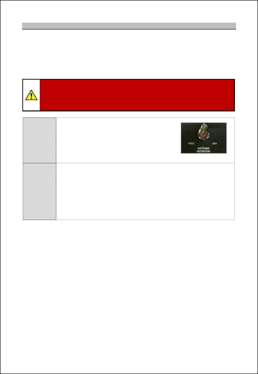
2.6 Man aloft switch/ antenna isolation.
Antenna rotation and transmission can be inhibited via a Man Aloft Switch (MAS) or an r<agXaaT IAA-
AeXXs keyswitch. These mechanisms can be used by a person who sees a potential hazard such as a
loose halyard and decides to protect the antenna.
When activated, the reason for loss of turning is detected by the system and is reported to the local
and remote users
Safety switches
Antenna
Rotation
keyswitch
The Antenna Rotation keyswitch is located on the door of the internally mounted
Radar Distribution Unit (RDU)
The key for the RDU keyswitch is captive when set to Free (enable rotation) but
can be removed when the keyswitch is to OFF.
When in the OFF position all single and 3-phase AC power to the antenna and
transceiver is isolated thus stopping antenna rotation and transmission.
The key should be removed and retained by the person who intends to enter the
potentially hazardous volume of the rotating antenna.
Man aloft
switch
(MAS)
The man aloft switch (MAS) is designed to be installed such that it is still viewable
for the person who is carrying out maintenance tasks.
Vb_h m_n ni nb_ •OFF jimcncih the transceiver/ gearbox is isolated from all single
and 3-phase AC power thus stopping the antenna rotation and transmission.
The Man Aloft switch, Motor ON/ OFF and Antenna Rotation keyswitch form part of a safety current
loop. This safety loop is purely hardware (no software), when the current loop is opened, AC mains
supplies to the transceivers and antenna inverter are switch OFF by use of contactors.
Kelvin Hughes recommends that the key switches noted above are used in conjunction with the man
aloft switch but also recommend that radar users carry out a safety assessment and risk mitigation
procedure in terms of interlocks prior to approving any work on the equipment.
Full details on isolating the systems from the AC supplies can be found in the planned maintenance
section of the relevant systems Operator & Maintenance handbook.
SBS-900 Shore Based Radar Systems
Chapter 2: Health & Safety warnings
KH-1602-2 issue 1: Standard SBS900 Systems Operator & Maintenance Handbook
Page 10 of 240
2.7 Anti-static handling
CAUTION: Handling of electrostatic-sensitive semiconductor devices
Certain semiconductor devices used in the equipment are liable to damage due to static
voltage. Observe the following precautions when handling these devices in their un-
terminated state, or sub-units containing these devices:
Persons removing sub-units from equipment containing these devices must be earthed
by a wrist strap and a resistor at the labelled point provided on/ within the equipment.
'Soldering irons used during authorised repair operations must be low voltage types
with earthed tips and isolated from the mains voltage by a double insulated
transformer.
'Outer clothing worn must be unable to generate static charges.
'Printed circuit boards fitted with these devices must be stored and transported in anti-
static containers.
'Fit new devices in a special antistatic safe handling area.
'Fully isolate and mechanically disconnect all sources of AC before attaching ESD
protective wrist straps to the various points in the system.
2.8 RoHS statement
Restriction of Hazardous Substances (RoHS): For details on RoHS statements please contact
Kelvin Hughes; contact details can be found in at the end of this handbook.
2.9 End of life disposal
When the equipment detailed in this handbook has reached the end of its serviceable life, the various
parts that make up the system must be disposed of in accordance with local industrial waste disposal
regulations.
Please contact your local regulatory body for disposal instructions or contact Kelvin Hughes for a list
of any potentially hazardous material contained within the system.
SharpEyenspecific disposal notice
Sb_ Rb[ljDs_x nl[hm]_cp_l(s) located within the transceiver enclosure are factory sealed units that
contains no field serviceable parts or lifed components.
Components within the Rb[ljDs_x jli]_mmil (all variants) contain traces of beryllium and trivalent
chromium.
Please contact Kelvin Hughes regarding the repair or a Rb[ljDs_x or its end of life disposal
instructions. Contact details for Kelvin Hughes can be found at the end of this handbook.

SBS-900 Shore Based Radar Systems
Chapter 2: Health & Safety warnings
KH-1602-2 issue 1: Standard SBS900 Systems Operator & Maintenance Handbook
Page 11 of 240
2.10 AC supplies
All AC mains powered equipment is provided with a
power rating plate that details the power requirements
and additional information for the equipment.
The power rating plate is attached to the front cover of the
equipment and indicates the following:
- Equipment name
- Part & serial numbers
- Equipment weight
- Supply voltage & frequency range(s)
- Current ratings
- IP rating
- Product hazard warnings Example of power rating plate
AC sources: Standard SBS-900 systems require the following switched and protected AC
inputs:
'Two sources of UPS supported 2 wire 115/ 230VAC single phase
supplies + protective earth.
'3 wire 440VAC three-phase supply + protective earth.
Health & safety: The information found on the power rating plates must be used in conjunction
with the Health & Safety notices shown in this handbook.
Cable requirements: The AC power requirements and cable specifications can be found in the
external interfacing section of the systems installation and commissioning
handbook.
Wiring: Wiring is to be carried out in accordance with the system manual using the
cables defined. Please refer to the systems installation and commissioning
handbook for full details.
Disconnection devices: To comply with CE approval and EN60950 requirements it is recommended
that the AC supplies to the system are made with clearly labelled, readily
accessible disconnection devices as follows:
Single phase: Standard CE approved mains outlet sockets (not supplied).
Three phase: Class B, red, 4-pole plug & socket (not supplied).
Fuses: All accessible fuses and over current protection devices are detailed in the
corrective maintenance section of the handbook.
Replacement fuses must be of the correct type and rating.

SBS-900 Shore Based Radar Systems
Chapter 2: Health & Safety warnings
KH-1602-2 issue 1: Standard SBS900 Systems Operator & Maintenance Handbook
Page 12 of 240
2.11 Grounding/ earth points
All parts of the system must be fully and correctly connected to a proven earth point prior to
connecting any source of AC power.
The system must never be switched ON or operated with an earthing point disconnected.
Connection point: All Kelvin Hughes equipment is fitted with a single protective earth connection
point which is indicated on the mechanical installation drawings.
Conductivity tests: During installation and maintenance, the earth connections must be tested for
conductivity using a high current impedance meter such as a Megger or
similar.
Wrist Straps: Fully isolate and mechanically disconnect all sources of AC before attaching
ESD protective wrist straps to the various points in the system.
SBS-900 Shore Based Radar Systems
Chapter 3: Software licensing and virus protection
KH-1602-2 issue 1: Standard SBS900 Systems Operator & Maintenance Handbook
Page 13 of 240
3 Software licensing and virus protection
3.1 Software
Only approved software may be used on Kelvin Hughes equipment. The use of unapproved or
unlicensed software on any Kelvin Hughes equipment is strictly prohibited. The use of such software
voids the warranty status of the unit.
Any Kelvin Hughes designed software supplied whether pre-installed, supplied on CD/ DVD or other
removable media, is the copyright of Kelvin Hughes Ltd, which will not accept any responsibility for
any damage or loss caused in whatever way by the use or misuse of the software. This copyright
applies to software that can be supply in various formats including but not restricted to CD, DVD, USB
memory device, email or obtained via the Kelvin Hughes agents download area.
Software supplied with Kelvin Hughes equipment may not be resold or re-distributed without the
express permission of Kelvin Hughes Ltd.
3rd party software supplied with the system such as the RadarView program remains the copyright of
the original manufacturer. See the manufactures documentation for copyright information.
3.2 Virus precautions
Many systems supplied by Kelvin Hughes Ltd including the optional Service Displays are now
PC based and it should be noted that such systems do not have anti-virus protection installed.
It is the responsibility of installation engineers, service engineers, maintainers and system users
to ensure that virus threats are not transferred to the system via removable media.
WARNING:Prior to use, all removable media used on or in Kelvin Hughes products
MUST be fully scanned for viruses on a PC installed with up to date anti-virus software.
Any media containing potential virus infections must not be used.
Charges relating to systems found to be infected with a virus will be passed onto the
company found to be using removable media that has not been suitably scanned.
Note: Kelvin Hughes cannot be held responsible for damage caused to systems
by virus infections.
Removable media referred to includes but is not restricted to USB memory sticks, USB hard drives,
`fijjs ^cm]m+ BC. CUCm [h^ [ff `ilgm i` l_gip[\f_ g_^c[-

SBS-900 Shore Based Radar Systems
Chapter 3: Software licensing and virus protection
KH-1602-2 issue 1: Standard SBS900 Systems Operator & Maintenance Handbook
Page 14 of 240
Page intentionally blank

SBS-900 Shore Based Radar Systems
Chapter 4: Handbooks
KH-1602-2 issue 1: Standard SBS900 Systems Operator & Maintenance Handbook
Page 15 of 240
4 Handbooks
The system handbook is split into two volumes that contain the following details. Additional
handbooks and technical data can be found in the handbook annexes:
KH-1602-1
Installation, Termination
and Commissioning Handbook
KH1602-2
Operation and Maintenance
Handbook
Contents:
1. Contents
2. Health and safety warnings
3. Software licensing & virus precautions
4. Handbooks
5. System overview
6. Equipment specifications
7. External interfacing
8. Options
9. Mechanical installation
10. Termination
11. Setting to work
12. Completion of installation
13. System acceptance test (SAT)
14. Abbreviations
15. Contacting Kelvin Hughes
16. Annex A: Antenna Sub system
17. Annex B: Supporting documentation Note
18. SBS-900 variants
19. Index
Contents:
1. Contents
2. Health and safety warnings
3. Software licensing & virus precautions
4. Handbooks
5. Technical description
6. Local operator instructions
7. Remote operator instructions
8. Service display/ RadarView control
9. Planned maintenance
10. Corrective maintenance
11. Abbreviations
12. Contacting Kelvin Hughes
13. Annex A: RadarView user manual
14. Annex B: Antenna sub system
maintenance Note
15. Index
Advanced Antenna / Antenna Turning unit (ATU):
ETahYTVgheXerf handbook: The SBS-900 series can be supplied with a range of Advanced
antennas and Antenna Turning Units.
The installation and maintenance instructions for the advanced
antennas and the antenna turning unit (ATU) are detailed in a
separate handbook located in Annex B of the Installation and
Commissioning handbook.
The Advanced Antenna Turning Unit and antenna must be installed
in accordance with the manufactures requirements which include but
are not restricted to: Health and safety, unpacking, lifting and
installation requirements.
Handbook reference: Installation and Maintenance Manual
Radar Antenna System type KAH20-AS-00000

SBS-900 Shore Based Radar Systems
Chapter 4: Handbooks
KH-1602-2 issue 1: Standard SBS900 Systems Operator & Maintenance Handbook
Page 16 of 240
Page intentionally blank
SBS
-
900 Shore
Ba
Ba
sed
Radar Systems
Chapter
5
:
Technical overview
KH
KH
-
1602 2
issue 1
:
Standard SBS900 Systems Operator & Maintenance Handbook
Page
17
17
of
240
5
Technical
overview
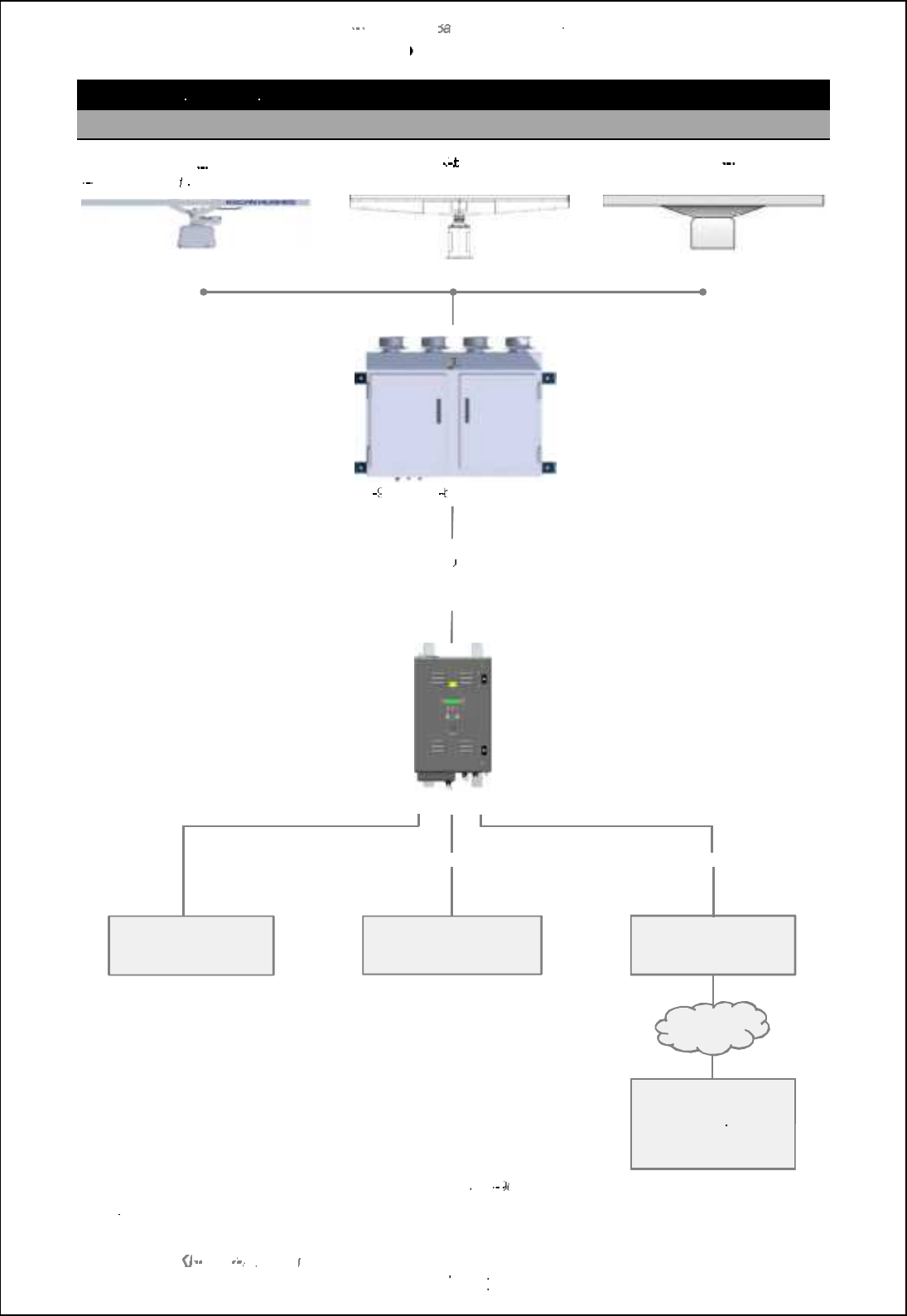
5.1
Generic
system
Standard X or S
-
band gearbox
S
-
band shown in for illustration purposes
Advance X
band gearbox
Third party X or S
-
band antenna
installation
Antenna options
.
Externally mounted SBS
900 X or S
band
6F?PN( WC\ RP?LQACGTCPCLAJMQSPC
Fibre optic
Or
Or
Cable connection
(System dependant)
Internally mounted
Radar Distribution Unit (RDU)
Serial & analogue signals
LAN
Example of a generic
SBS
-
900 system
Note:
Third party antenna interfacing is subject to initial inspection and compatibility checks.
WAN
Track extractor
Optional range of
service displays
External command
and display
system
Site mains
SBS-900 Shore Based Radar Systems
Chapter 5: Technical overview
KH-1602-2 issue 1: Standard SBS900 Systems Operator & Maintenance Handbook
Page 18 of 240
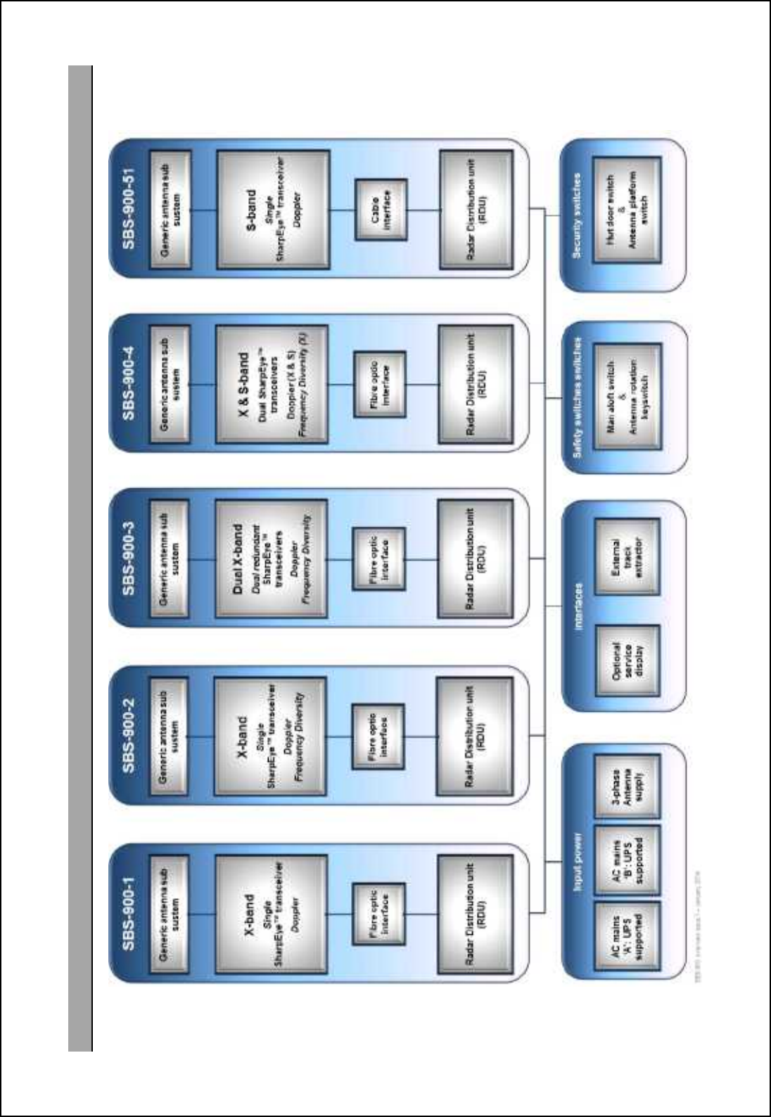
5.2 SBS-900 overview

SBS-900 Shore Based Radar Systems
Chapter 5: Technical overview
KH-1602-2 issue 1: Standard SBS900 Systems Operator & Maintenance Handbook
Page 19 of 240
Page intentionally blank
SBS-900 Shore Based Radar Systems
Chapter 5: Technical overview
KH-1602-2 issue 1: Standard SBS900 Systems Operator & Maintenance Handbook
Page 20 of 240
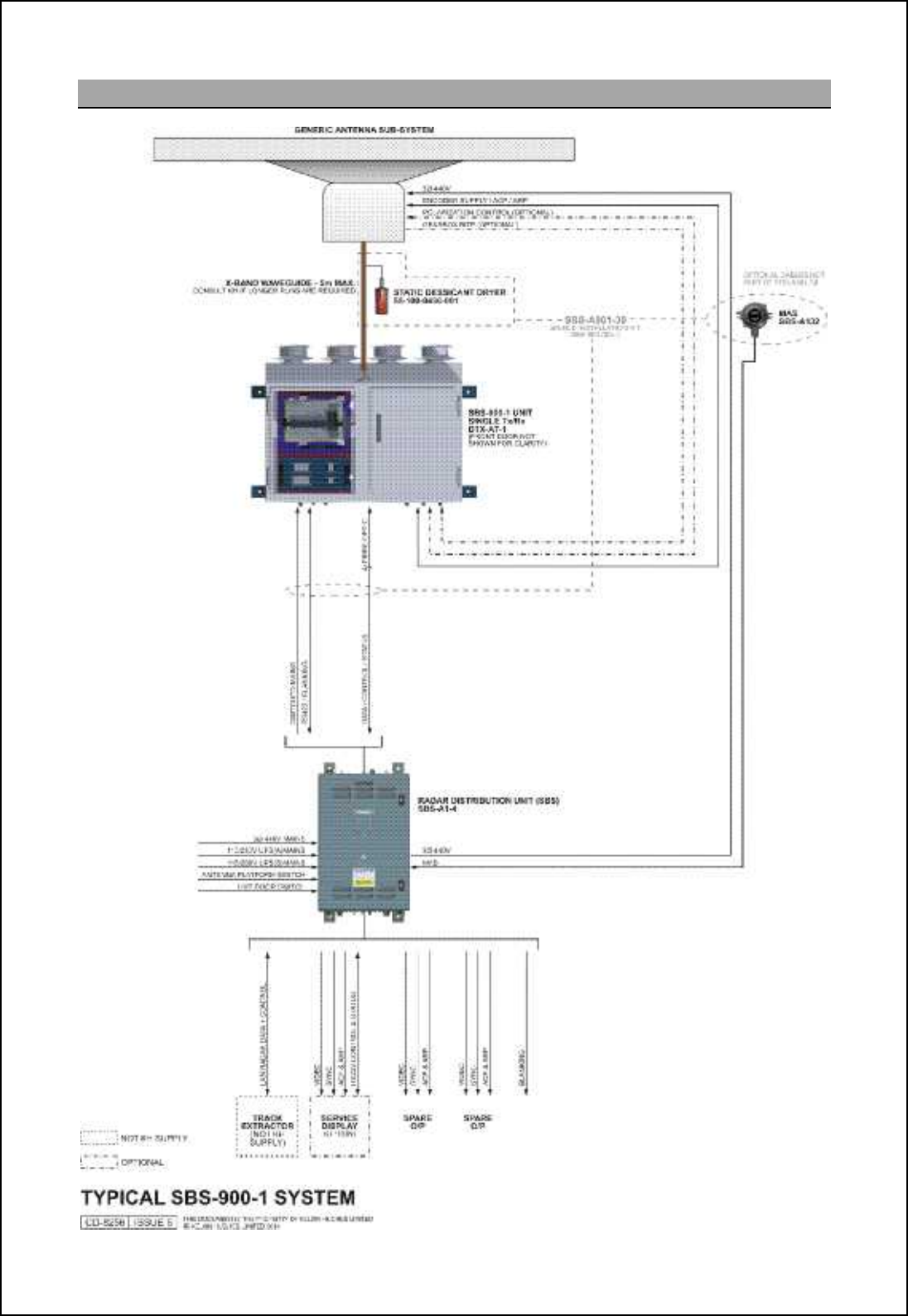
5.3 SBS-900-1
SBS-900 Shore Based Radar Systems
Chapter 5: Technical overview
KH-1602-2 issue 1: Standard SBS900 Systems Operator & Maintenance Handbook
Page 21 of 240
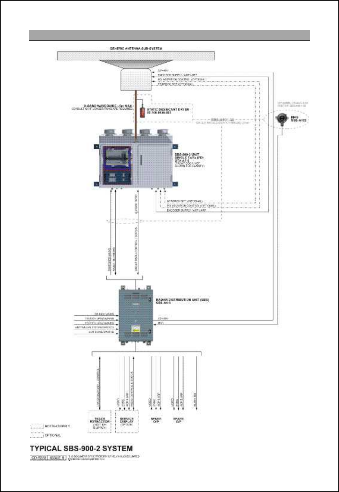
5.4 SBS-900-2
SBS-900 Shore Based Radar Systems
Chapter 5: Technical overview
KH-1602-2 issue 1: Standard SBS900 Systems Operator & Maintenance Handbook
Page 22 of 240
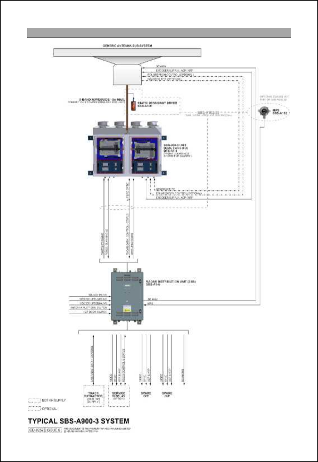
5.5 SBS-900-3
SBS-900 Shore Based Radar Systems
Chapter 5: Technical overview
KH-1602-2 issue 1: Standard SBS900 Systems Operator & Maintenance Handbook
Page 23 of 240
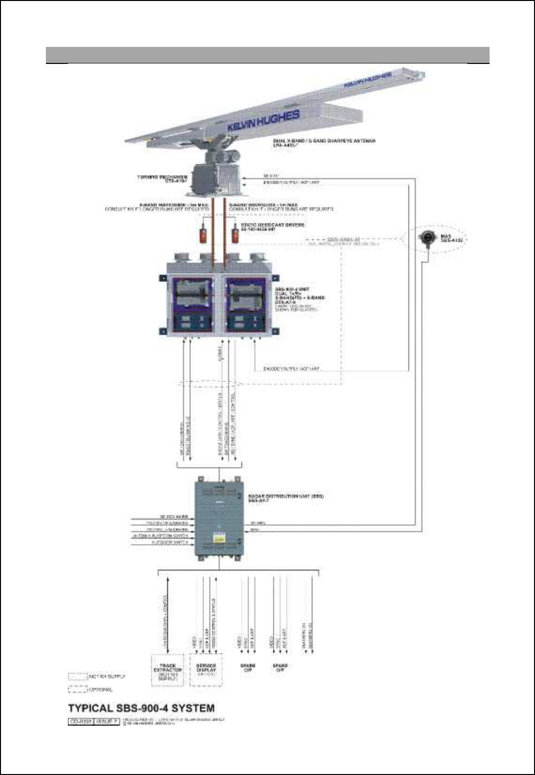
5.6 SBS-900-4
The LPA-A455 is a combination of
the standard LPA-A55 (x-band)
and the LPA-A3 (S-band) antennas
which are fitted to a DTX-A19
gearbox that has a dual rotating
joint.
The SBS-900-4 allows the operator
to select between X or S band
transmission.
SBS-900 Shore Based Radar Systems
Chapter 5: Technical overview
KH-1602-2 issue 1: Standard SBS900 Systems Operator & Maintenance Handbook
Page 24 of 240
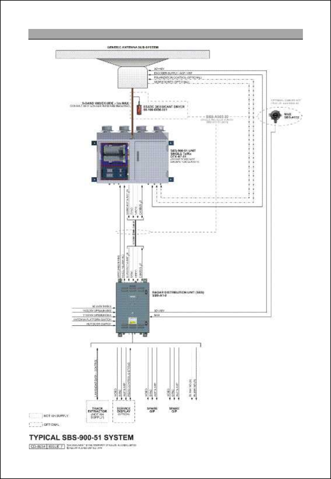
5.7 SBS-900-51
SBS-900 Shore Based Radar Systems
Chapter 5: Technical overview
KH-1602-2 issue 1: Standard SBS900 Systems Operator & Maintenance Handbook
Page 25 of 240
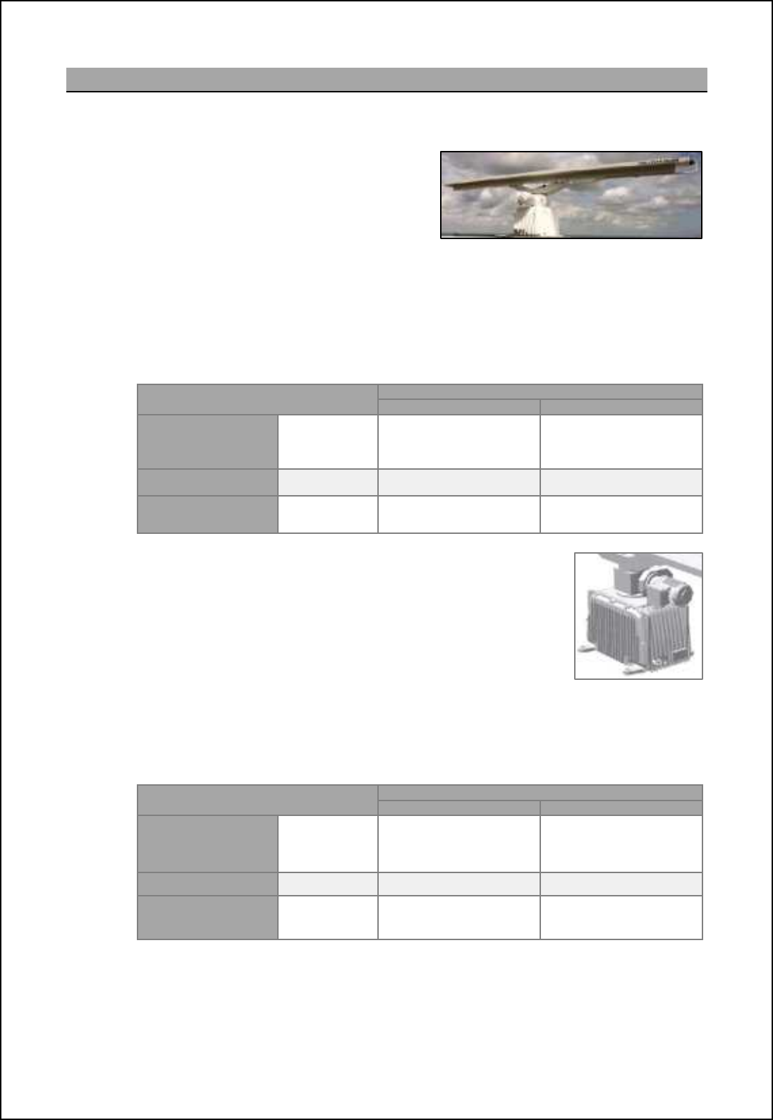
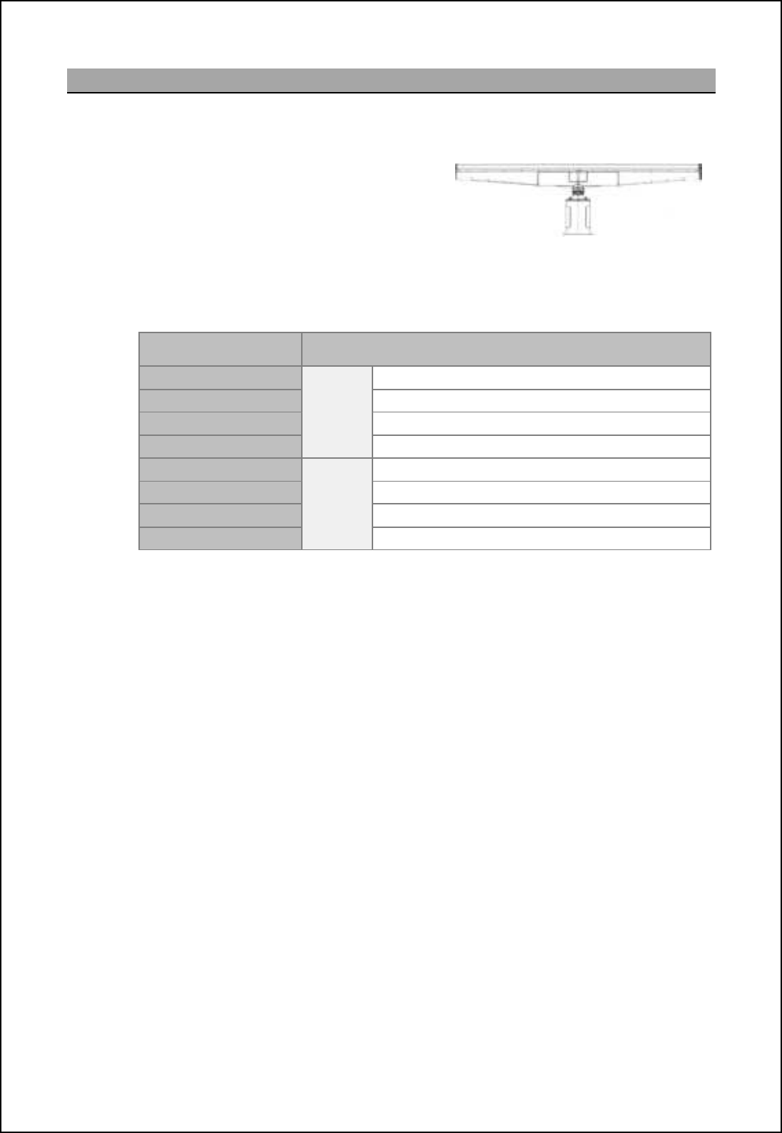
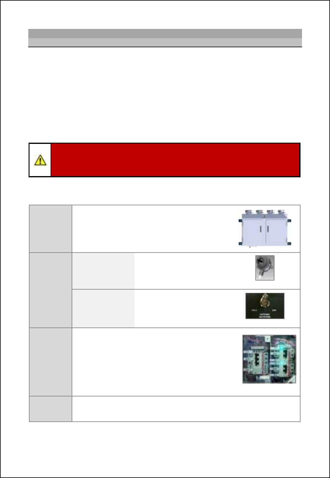
5.8 Standard antenna sub system
The standard antenna solution comprises a Kelvin Hughes manufactured gearbox and range of Low
Profile Antennas (LPA) that can be used on all variants of the SBS-900 range:
Antenna:The gearbox can be fitted with a range of X
or S-band Low Profile Antennas (LPA).
The antenna utilises polyrod technology
and a horizontally polarised end fed slotted
array enclosed in a polycarbonate plastic
case. Example of a Kelvin Hughes X-band LPA
Single antenna: The waveguide feed from the antenna is connected to the rotating joint of
the gearbox.
Combined X & S band antenna: The waveguide from each antenna is connected to a
special dual waveguide connection at the rotating joint of the gearbox.
SBS system
Equipment colour
Signal white RAL9003 Silver grey RAL7001
X-band SBS-900-1
SBS-900-2
SBS-900-3
LPA-A37 (3.7m)
or
LPA-A55 (5.5m)
LPA-A37-BAAA (3.7m)
or
LPA-A55-BAAA (5.5m)
S-band SBS-900-51 LPA-A3 (3.9m) LPA-A3-BAAA (3.9m)
Combined
X & S-band SBS-900-4 LPA-A455
(5.5m & 3.9m) LPA-A455-BAAA
(5.5m & 3.9m)
Gearbox: The synchronous antenna motor is driven by a 3-phase voltage
which is supplied and controlled from an inverter within the RDU.
This inverter is configured to provide a soft start and a soft stop for
the Motor and adjustable antenna RPM. Note Three phase power is
connected via a junction box mounted on the motor.
A DC supply from the transceiver enclosure powers the ACP/ ARP
encoder within the gearbox enclosure. ACP and ARP signals are
connected to the transceiver enclosure by cables.
The gearbox has a removable service access door that allows easy access to the ACP/
ARP connections, the encoder and the RF coupling in S-and systems. There are no other
electronics within the unit.
SBS system Equipment colour
Signal white RAL9003
Silver grey RAL7001
X-band SBS-900-1
SBS-900-2
SBS-900-3 DTX-A3-AXZX DTX-A3-BXZX
S-band SBS-900-51 GTX-A11 GTX-A11-BAAA
Combined
X & S-band SBS-900-4 DTX-A19 DTX-A19-BAAA
Specifications:Full specifications on the standard antenna and gearbox range can be found in the
installation and commissioning handbook (KH-1602-1).
Note: Antenna speeds/ RPM are factory configured.
SBS-900 Shore Based Radar Systems
Chapter 5: Technical overview
KH-1602-2 issue 1: Standard SBS900 Systems Operator & Maintenance Handbook
Page 26 of 240
5.9 Advanced antenna sub system
The advanced antenna solution comprises an X-band antenna and Antenna Turning Unit (ATU) that
can be used on with the SBS-900-1, SBS-900-2 and SBS-900-3 X-band systems.
Antenna:The advanced antenna sub system
comprises of a HI-gain 5.5 or 6.4m antenna
The antenna is rotated using a servo motor
at 1 RPM but can be configured during
setting to work only for speeds between 1
and 10 RPM.
Example of a 6.4m advanced antenna
The waveguide feed from the antenna is connected to the rotating joint of the Antenna
Turning Unit.
Antenna range Description
SBS-A55-10HW
10 RPM
5.5 m, Horizontal polarisation, white
SBS-A55-10CW 5.5 m, Circular polarisation, white
SBS-A64-10HW 6.4 m, Horizontal polarisation, white
SBS-A64-10CW 6.4 m, Circular polarisation, white
SBS-A55-20HW
20 RPM
5.5 m, Horizontal polarisation, white
SBS-A55-20CW 5.5 m, Circular polarisation, white
SBS-A64-20HW 6.4 m, Horizontal polarisation, white
SBS-A64-20CW 6.4 m, Circular polarisation, white
Note: White is according RAL 9016. For grey variants (RAL 7001) the above Kelvin Hughes part numbers
have suffix G instead of W.
Gearbox: Two Antenna Turning Units are available:
- ST1-F10 (10 RPM)
- ST1-F20 (20RPM)
Both are powered by a three-phase supply generated and controlled by a static inverter
mounted within the RDU. This inverter is configured to provide a soft start and a soft stop
for the Motor and adjustable antenna RPM. Note
Three phase power is connected via a junction box mounted within the Antenna Turning
Unit. The gearbox is fitted with an encoder giving 1024 @BOm [h^ 0 @QO [h^ m_lpi ginil-
A +5VDC supply from the transceiver enclosure powers the ACP/ ARP encoder within the
gearbox. ACP and ARP signals are connected to the transceiver enclosure by cables.
Handbook: The installation, termination, commissioning processes and requirements for the
advanced range of antennas and the ST1-F10 & ST1-F20 Antenna Turning Unit (ATU) are
not included in this section. Note
Please refer to Annex B or to the handbooks provided with the equipment for full
installation details.
Note: Antenna speeds/ RPM are factory configured.
SBS-900 Shore Based Radar Systems
Chapter 5: Technical overview
KH-1602-2 issue 1: Standard SBS900 Systems Operator & Maintenance Handbook
Page 27 of 240
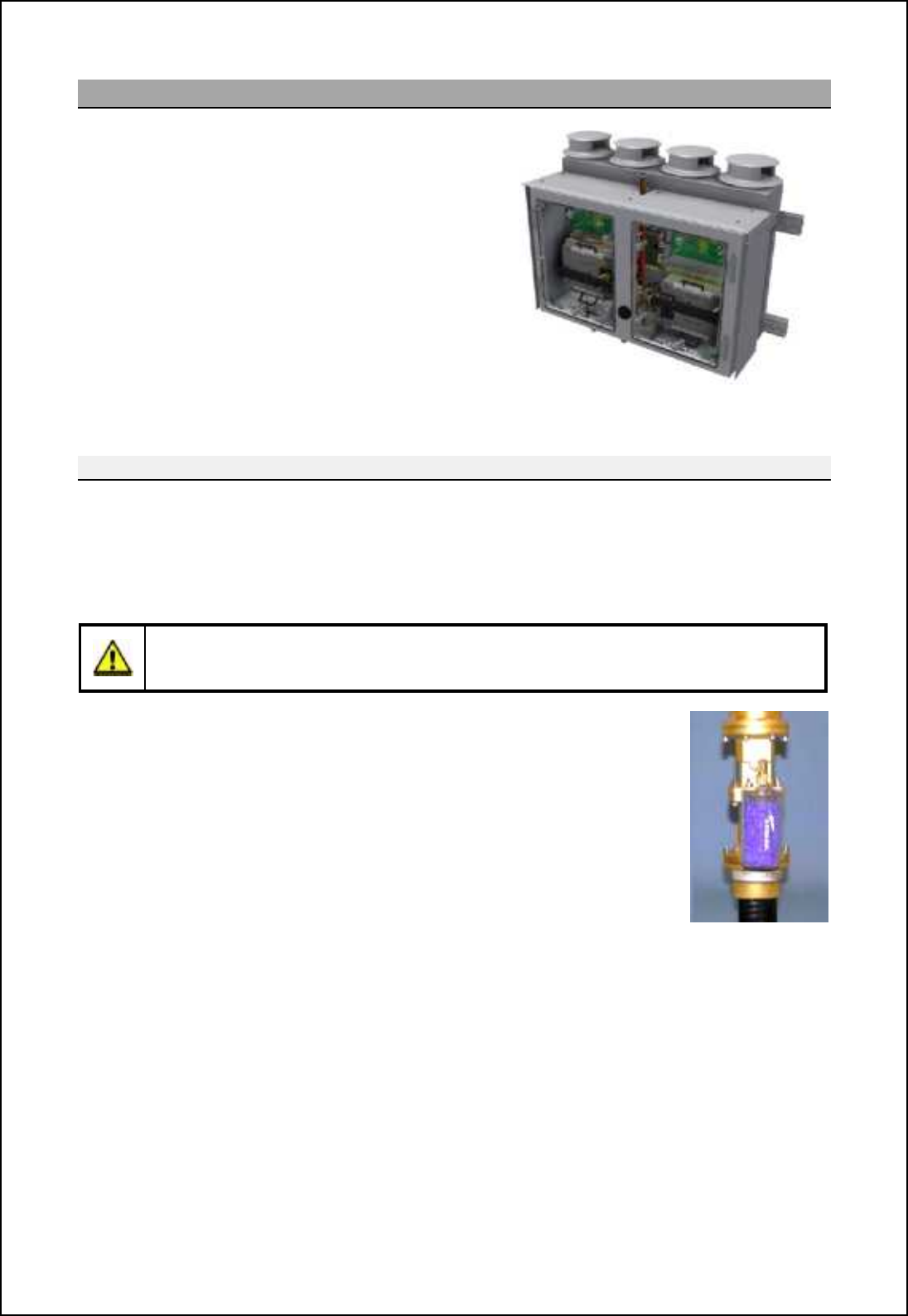
5.10 Transceiver enclosure
The DTX-A7 is a range of external mounted
waterproof enclosures that contains the relevant X or
S-Band SharpEyeTM transceiver(s), an azimuth signal
interface, system power supplies, a waveguide switch
(where required) and an RF connection to the antenna
sub-assembly.
The system is designed to be externally mounted and
is convection cooled by the use of heatsinks and four
wind turned rotary ventilators mounted on top of the
assembly.
For areas operating in high ambient temperatures
additional powered cooling fans can be fitted as an
option (SBS
-
A179).
Example of a DTX-A7-3 shown with access doors
removed for clarity
Connection to antenna
The system is connected to the antenna sub-system via a bespoke waveguide connected to the top of
the system. The waveguide/ flexwell is supplied preassembled with a static desiccator drying unit (55-
100-0436-001).
Turning data (ACP/ ARP) is interfaced to the enclosure from the turning unit via cable connections.
NOTICE: Maximum flexwell/ waveguide distance
The maximum flexwell/ waveguide run between the DTX-A7 transceiver enclosure and the
antenna sub-assembly is 5 metres.
Waveguide dryer: A static desiccator is supplied pre-assembled onto the
waveguide as part of all SBS-900 systems.
The unit is a totally passive device and requires no electrical power.
It connects directly into a gas inlet port that forms part of the flexwell/ waveguide
assembly.
The clear wall of the unit allows visual inspection of the desiccant condition. As
moisture is adsorbed the colour will change from deep blue to pink/white. When
80% of the desiccant material has changed
colour, the unit should be replaced
.
A pressurised waveguide dryer (SBS-A131-1) is also available as an option.

SBS-900 Shore Based Radar Systems
Chapter 5: Technical overview
KH-1602-2 issue 1: Standard SBS900 Systems Operator & Maintenance Handbook
Page 28 of 240
Connection to Radar Distribution Unit
Data Signals: The following signals are transferred between the DTX-A7 enclosure and the Radar
Distribution Unit:
'Digital signals in the form of radar video, display sync, ACP and ARP
'System control, status and BITE data
'Blanking signals
Connections between the two units are via:
'SBS-900-1, -2, -3 & -4: Fibre optic cable
'SBS-900-51: Cable connection
Power: The enclosure is AC powered and controlled by the Radar Distribution Unit. In single
transceivers a single AC supply is provided, in dual systems two AC supplies are
provided (one for each transceiver).
Internal AC-DC power supplies provide all the internal DC power requirements of the
enclosure. A DC supply is also provided to power the ACP/ ARP encoder in the
antenna sub-system.
- For Standard systems sub-systems the encoder supply is +15VDC
- For Advanced antenna sub- systems the encoder supply is +5VDC
Over current protection devices: The Transceiver enclosure is fitted with internal breakers for the
AC supply(s) to the enclosure.
-MCB1 isolates the AC supply to the left hand side of the enclosure.
-MCB2 isolates the right hand side of the enclosure.
All breakers must be in their OFF position before commencing any form of service or
maintenance work on the system.
Access: Access to the unit is via two lockable (8mm hex key), waterproof doors mounted on
the front of the unit.
Location: The DTX-A7-X waterproof enclosure is designed to be externally mounted located
within 5 metres of the gearbox/ antenna turning unit.
Interlocks: Maintenance and ENCOM safety switches are provided via an Antenna Rotation
keyswitch fitted on the RDU and an externally mounted Man Aloft switch
Breakers for the AC input are located within the transceiver enclosure.
If no azimuth (rotation) is detected, the SharpEye will automatically switch to standby
within 60 seconds of signal loss.

SBS-900 Shore Based Radar Systems
Chapter 5: Technical overview
KH-1602-2 issue 1: Standard SBS900 Systems Operator & Maintenance Handbook
Page 29 of 240
K[Tec>lXn geTafVX\iXe
SharpEyeTM transceiver technology radically departs from conventional marine navigation transceivers
through the transmission of low power RF pulses and application of pulse compression and Doppler
techniques. The technology benefits from the following:
'Solid state transmitter for high reliability 'Dynamic range of 126 dB (including sensitivity
time constant (STC) & pulse compression gain)
'Digital pulse compression 'Minimum discernible signal (MDS) of
-125dBm
'Receiver noise figure <5.5dB 'Internal monitoring, no external components
required to monitor operation
'Pulse Doppler processing for improved rain
and sea clutter rejection
'Range discrimination: 7.5nm (24nm) and
15nm (48nm)
Solid state technology: Solid state transistors obviate the need for a warm-up time. When the
Radar Distribution Unit is switched ON the SharpEyeTM is powered.
When a Run command is received by the transceiver, it is ready for
transmission within 40 seconds.
Output power: When transmitting, the amplifiers generate a nominal peak power of
170Watts with a maximum duty cycle of 13% at the transceiver
output flange.
System monitoring: Comprehensive built in test (BIT) facilities within the transceiver
provide on-line monitoring of the following parameters within the
transceiver:
'RF power 'Antenna system
VSWR
'Power supplies
'Temperature 'Receiver
sensitivity
'Antenna rotation
data
Should the system detect a fault condition which could lead to early
failure of the transceiver, i.e. a high VSWR, then the transceiver
switches to a low power state which permits transmission to continue
in the short term. The built in test monitoring also ionjonm [ •Kiq QE
Oiq_l q[lhcha g_mm[a_ c` nb_ QE jiq_l ionjon `[ffm \_fiq 0// V-
Sb_ ^_mcah cm •`[cf-mi`n nb_l_\s jlipc^cha al[]_`of ^_al[^[ncih ch nb_
event of single or multiple transistor failures.
SBS-900 Range: System ID SharpEyeTM
Transceiver Doppler Frequency
Diversity
SBS-900-1 X-band & %
SBS-900-2 X-band & &
SBS-900-3 X-band
(dual redundant) & &
SBS-900-4 X and S-band
(dual transceiver) &
(X & S-band)
&
(X-band only)
SBS-900-51 S-band & %
SBS
-
900 Shore
Ba
Ba
sed
Radar Systems
Chapter
5
:
Technical overview
KH
KH
-
1602 2
issue 1
:
Standard SBS900 Systems Operator & Maintenance Handbook
Page
30
30
of
240
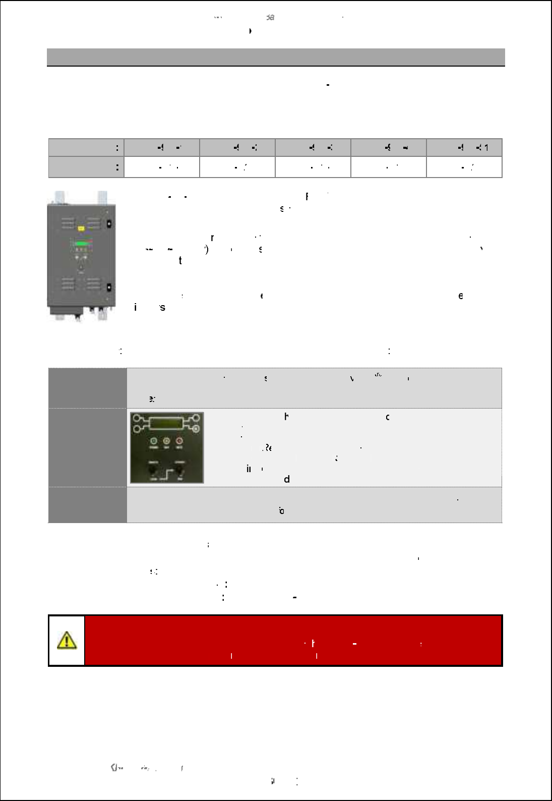
5.11
Radar Distribution Unit
There are 5 Radar Distribution Units used in the
standard
SBS
-
900
range
with the only difference
being the configuration and interfacing of the individual units.
The operation of each of the Radar Distribution Units is identical.
SBS system
:
SBS
900
1
SBS
900
2
SBS
900
3
SBS
900
4
SBS
900
51
51
RDU
SBS
-
A1
A1
-
4
SBS
-
A1
A1
-
5
SBS
-
A1
A1
-
6
SBS
-
A1
A1
-
7
SBS
-
A1
A1
-
8
The SBS
-
A1
A1
-
X Radar Distribution Unit (
RDU
)
is a radar processing and distribution
unit that accepts radar video input
s from the external transceiver
enclosure
and
provides signal outputs in digital form.
The RDU accepts
radar
data
via fibre optic cable or cable connection (cable on
SBS
900 51 only
) and
output
s
digit
ised video including control and status data
via a
LAN
to
to
the
track extractor.
A
Kelvin Hughes TCP/IP specific protocol
is used
based on the Asterix format
.
The RDU al
so provides an int
erim two way serial interface for
a range of s
ervice
d
isplay
s which offer local
control of the
system for maintenance and monitoring
purposes.
Control modes
: The RDU can be operated in either of the following modes
Remote control
In normal operation,
the
system
i
s remotely controlled
via a 3
rd
rd
rd
party
command & display
system or track extractor
and WAN with the RDU acting as an interface.
Note
: The infrastructure of the track extractor and WAN are not detailed in this handbook.
Local control
In local control, t
he system can be
locally
operated using controls
mounted on the front of the Radar Distribution Unit (RDU); controls
include:
-
Local
or
R
emote
control selection.
-
Local transceiver
Run
and
Standby
control.
-
View
ing
of status and BITE data on an integrated LCD display.
-
Viewing and a
djustment of system configurations.
Optional
service display
A range of optional service displays are available which enables a maintainer to view,
control and display the radar locally f
or commissioning and maintenance purposes.
AC Breakers:
To
comply with CE
and EN60950 requirements it is recommended that the
AC
connections to the RDU are via clearly labelled, readily accessible
disconnection
device
s:
s:
-
Single phase
supply
:
Standard CE approved mains outlet sockets (not supplied).
-
Three phase
supply
:
Class B, red, 4
pole plug & socket (not supplied).
Antenna Rotation Safety Notice
Depending on the status of the safety switches, w
hen three
phase power
is
is
connected and
connected and
switched ON, the antenna
may rotate
immediately
regardless of the RUN command status.

SBS-900 Shore Based Radar Systems
Chapter 5: Technical overview
KH-1602-2 issue 1: Standard SBS900 Systems Operator & Maintenance Handbook
Page 31 of 240
AC requirements
Single phase: Two independent sources of UPS supported, single phase, 115/ 230VAC supply are
connected to the RDU.
The AC voltages are fed to an AC-DC power supply via user accessible breakers
located within the RDU. The internal power supply provides all the DC power
requirements of the RDU.
Switched AC supply is sent from the RDU to the DTX-A7 transceiver enclosure.
3-phase: A 440VAC 3-phase input is fed via a user accessible breaker to an internal static
inverter. This generates and controls the three phase requirements of the turning
mechanism solution.
Caution: When the three phase supply is connected and switched ON, the inverter
unit is powered and sends three-phase voltages to the antenna motor which may
rotate immediately (see safety switches).
Safety switches: A normally closed safety current loop is provided for the serial connection of safety
switch contacts including an external Man Aloft switch.
Antenna rotation switch: An Antenna Rotation safety keyswitch
is provided on the RDU and is part of the safety current loop. This
switch can be set to OFF, removed and retained by the
maintainer for safety.
Man Aloft Switch (MAS): An externally mounted switch that can
be set to Free (rotate) or OFF.
When either the Antenna Rotation or Man Aloft switches are set
to OFF or if the safety current loop is broken/ open, the single and
3-phase AC supplies from the RDU to the transceiver enclose
and gearbox are isolated thereby stopping Antenna Rotation and
system transmission.
RDU Antenna
Rotation switch
External Man Aloft
Switch
Security Switches: There is also provision for an optional set of normally closed Antenna Platform
and a Hut Door switches that are used for monitoring purposes only. These switches
do not isolate or control any part of the system, when fitted and enabled, the systems
report the status of these switches to the RDU.

SBS-900 Shore Based Radar Systems
Chapter 5: Technical overview
KH-1602-2 issue 1: Standard SBS900 Systems Operator & Maintenance Handbook
Page 32 of 240
5.12 System control
Remote
Control
In normal operation, the system is remotely controlled by the track extractor with the RDU
acting as an interface.
An optional Service Displays enables the system maintainer to view, control and display
the system for maintenance purposes.
Local
Control
In Local control, the system can be operated using controls mounted
on the front of the Radar Distribution Unit (RDU); controls include:
-Local or Remote control selection.
- Local transceiver Run and Standby control.
- Viewing of status and BITE data on an integrated LCD display.
- Viewing and adjustment of system configurations.
Safety switches: The following switches are on a safety current loop which, when broken/
open isolate the transceiver and turning unit from the single and three-phase
AC supplies thus stopping antenna rotation and transmission.
-Antenna Rotation: A door mounted removable keyswitch to stop antenna
rotation & transmission.
-Man Aloft Switch: An externally masthead mounted switch to stop antenna
rotation & transmission.
Security switches:Hut door and antenna platform switch.
The state of these switches is reported to the track extract, service display
etc. The switches do not isolate or control any aspect of the system and are
for switch status reporting only.
SBS
-
900 Shore
Ba
Ba
sed
Radar Systems
Chapter
5
:
Technical overview
KH
KH
-
1602 2
issue 1
:
Standard SBS900 Systems Operator & Maintenance Handbook
Page
33
33
of
240
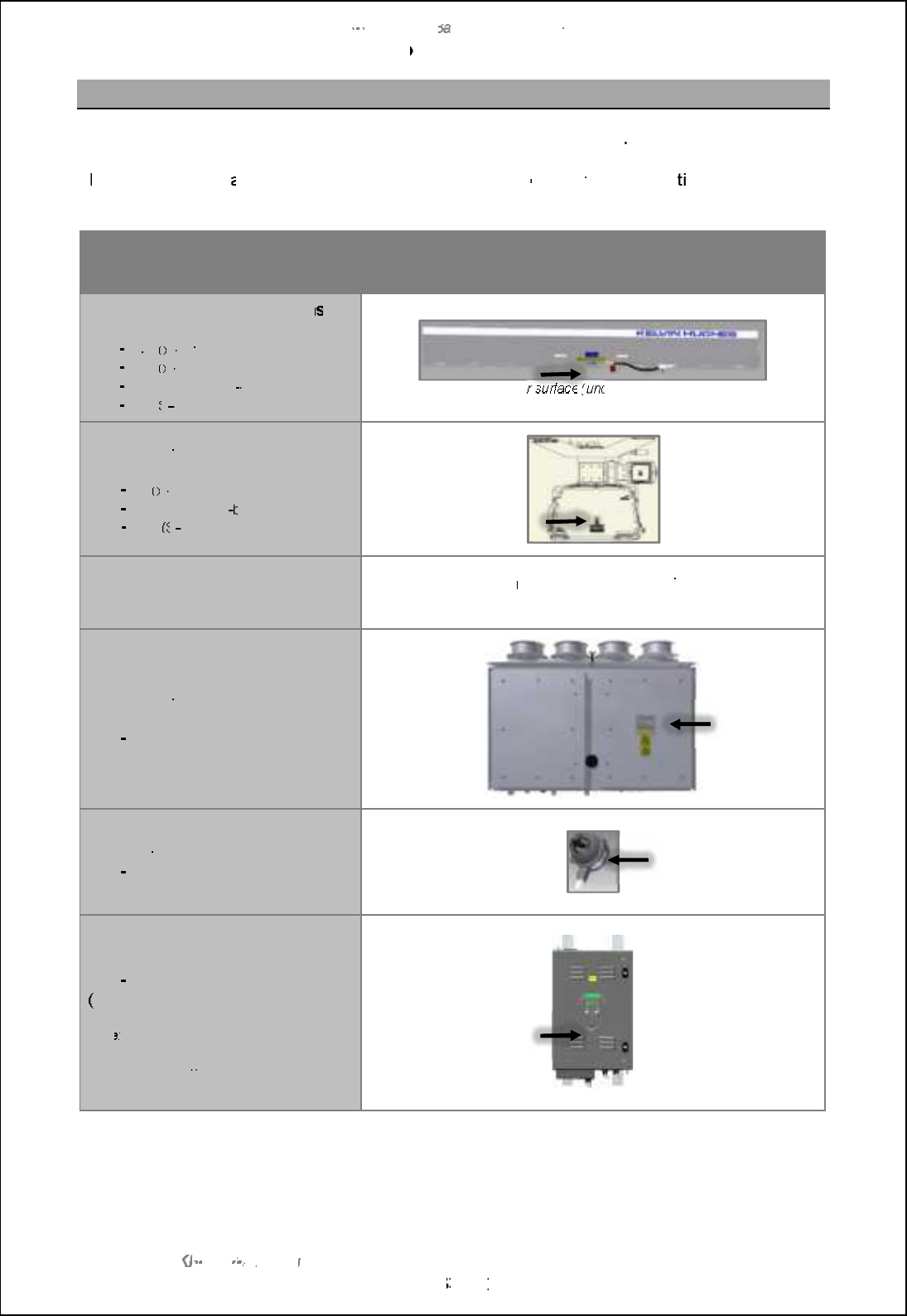
5.13
Unit identification
The equipment included in the SBS
-
900
series can be identified as follows
T
he full part and seri
al number of
a
system should always be
quoted
when contac
ting Kelvin Hughes
for assistance or spares.
Description
Part number & serial number location
(arrow indicates label position)
Standard
low profile antenna
s
(all variants)
LPA
A37
(x
(x
-
band)
LPA
A55
(x
(x
-
band)
LPA
A455
(dual X & S
-
band)
LPA
A3
(S
(S
band)
Lower
surface
(underside) of LPA
Standard gearboxes
(all variants)
DTX
-
A3
(x
(x
-
band)
DTX
-
A19
(dual X & S
band)
GTX
-
A11
(S
(S
band)
Advanced systems
Antenna and Antenna Turning Unit
(ATU)
Please refer to the
manufacturers
handbook
supplied with the
Advanced antenna for details
Transceiver Enclosure
(all variants)
DTX
-
A7
Man aloft switch
SBS
-
A132
Radar distribution unit
SBS
-
A1
(
all variants)
Note
: If a option has been added to a
system, an additional label is added noting
the option number

SBS-900 Shore Based Radar Systems
Chapter 5: Technical overview
KH-1602-2 issue 1: Standard SBS900 Systems Operator & Maintenance Handbook
Page 34 of 240
Page intentionally blank

SBS-900 Shore Based Radar Systems
Chapter 6: Local operation instructions
KH-1602-2 issue 1: Standard SBS900 Systems Operator & Maintenance Handbook
Page 35 of 240
6 Local operation instructions
6.1 Antenna rotation warnings
ANTENNA ROTATION SAFETY NOTICE:
When three-phase power is connected to the system and switched ON, the antenna will
rotate immediately regardless of the RUN command status (see conditions below).
When three-phase AC mains supplies are connected and switched ON using the breakers located
within the RDU, the antenna may rotate immediately.
The system will only transmit when a RUN command is received from the track extractor, service
display or is set to RUN using the Local controls located on door of the Radar Distribution Unit.
Antenna rotation can be stopped by any of the following methods:
Antenna Rotation Switch: Place the Antenna Rotation keyswitch located on the front of the
Radar Distribution Unit into the OFF position.
Man Aloft Switch:Place the masthead Man Aloft switch into the OFF position.
RDU Breakers: Isolate the three phase AC supplies using the breaker located within
the Radar Distribution Unit.
Software Emergency Stop: Press the Antenna stop button in the service display RadarView
software (see below).
Caution: The software Antenna Stop function from the Service Display MUST NEVER be
used as the primary means of system isolation for working aloft.
SBS
-
900 Shore
Ba
Ba
sed
Radar Systems
Chapter
6
:
Local operation instructions
KH
KH
-
1602 2
issue 1
:
Standard SBS900 Systems Operator & Maintenance Handbook
Page
36
36
of
240
6.2
Local control o
verview
6.2.1
RDU
Local
controls
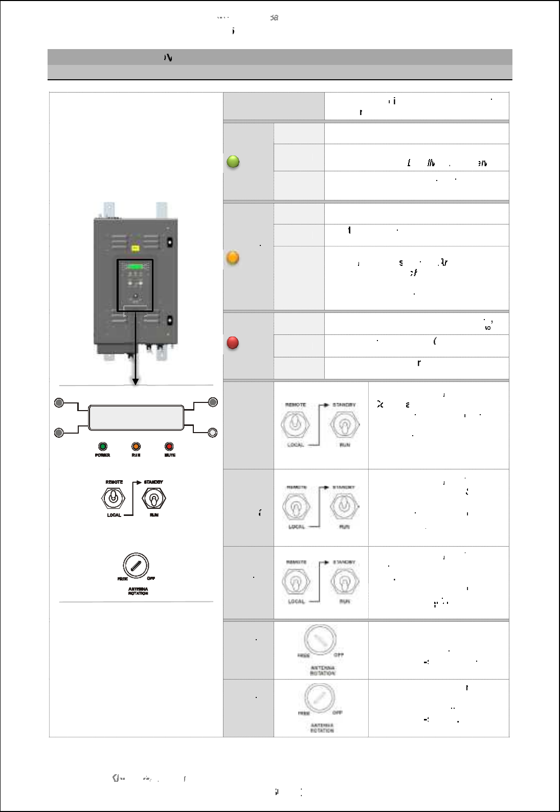
Radar Distribution Unit
front panel
LCD display
A backlit LCD
d
isplay shows the system
status,
menus, error and alarm messages
Green
Green
LED
LED
Power
Power
OFF
OFF
No power, the RDU is not switched ON
ON
ON
The power is switched ON and the system
is
being controlled
Local
ly
ly
or
Remote
ly
ly
Flashing
The power is switched ON
but
the system
is
not controlled (no master)
Yellow
Yellow
LED
LED
RUN
RUN
OFF
The system is in standby
ON
ON
The
transceiver
has entered RUN mode
and is transmitting
Flashing
The system is unable to run because:
-
The
Man Aloft
switch or
A
ntenna
Rotation
key switc
hes
are set
in the
OFF position
-
A fault is preventing transmission; check
the status of the unit
Red
Red
LED
LED
MUTE
MUTE
OFF
No Mute commands are being received
the system is transmitting for a full 360
ON
ON
The transceiver is muted
(no
transmission)
Flashing
The system is operati
ng with sector
blanking applied
Switch
set to
Remote
The system is in
Remote
C
ontrol
and is operated from
the track extractor or
r
emote
command
&
display system.
The Standby/ RUN switch has
no function
and can be in any
position
Switches
Switches
set to
Local
&
Standby
The system is in
Local
control
with the transceiver in
Standby
mode.
The track extractor or
r
emote
command
&
display system has
no control
Note
.
Switches
Switches
set to
Local
&
RUN
The system is in
Local
control
and the transceiver is set to
RUN
The track extractor or
r
emote
command and display system
has no control
Note
.
Antenna
rotation
OFF
The antenna is inhibited.
All AC mains power to the
transceiver enclosure
and
antenna sub
system
is isolated.
The system cannot be run.
Antenna
rotation
FREE
The antenna is free to
rotate.
Power is applied to the
transceiver enclosure and
antenna sub
system
.
The system is available for use.
SBS
-
900 Shore
Ba
Ba
sed
Radar Systems
Chapter
6
:
Local operation instructions
KH
KH
-
1602 2
issue 1
:
Standard SBS900 Systems Operator & Maintenance Handbook
Page
37
37
of
240
6.2.2
Remote
/
Local
switch
A
switch on the front of the
Radar Distribution Unit
allows the selection of
R
emote
or
or
L
ocal
operation
The following explains the basic operation of the system in these two modes.
Antenna Rotation
Warning
:
D
epending on the position of the safety switches, t
he antenna
will
rotate regardless of the
position of the
R
emote/
L
ocal
or
S
tandby/
R
un
un
switches.
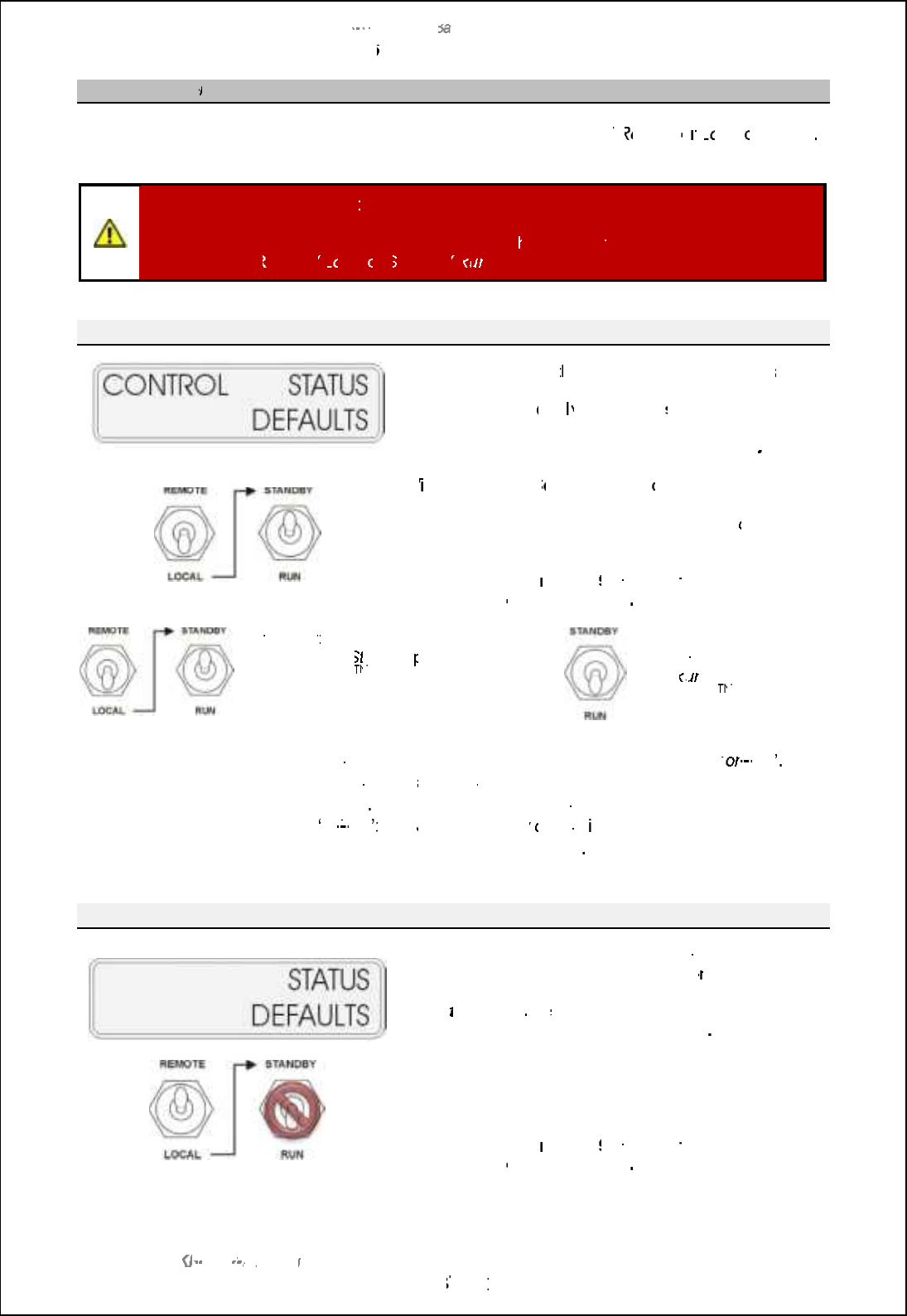
Local
With Local selected, t
he system is in
Local
control
and is
used by the installation engineer or system maintainer to
configure, test or
l
ocal
ly control the
system
,
Remote
control of the system is not possible
W
ith the
optional S
ervice
D
isplay
off
-
line, system control,
status and default information can be accessed, adjusted
and viewed in the display panel which shows
control,
status
and
defaults:
See Section
6.2.4
pages 39
39
onwards
for full details on
the
operation
of the front panel
.
S
tandby
: With the Standby/ Run
switch in the
S
tandby
position,
the SharpEye
TM
TM
is in a ready
state but does not transmit.
Run:
With the
Standby/ Run switch in
the
R
un
un
position, the
SharpEye
TM
TM
transmits.
Local
control disabled?
When the optional Service D
GQNJ?WGQAMLLCARCB?LBGQe
on
on
-
line ,
Local
control
at the RDU
is not possible as the service display has
control
For RDU
Local
control, the optional service display must be
•
off
-
line ; see Service Display
control
in the following section for
details on Service Display operation
.
Remote
When Remote is selected, the system is controlled by the
external command and display system
or
or
track extractor.
The
S
tandby/
R
un
switch has no function
and
l
ocal
/
Service Display
control is not possible
System status and default information can still be
accessed and viewed in the display panel which shows
status
and
defaults:
See Section
6.2.4
pages 39
39
onwards
for full details on
the
operation
of the front panel
.
SBS-900 Shore Based Radar Systems
Chapter 6: Local operation instructions
KH-1602-2 issue 1: Standard SBS900 Systems Operator & Maintenance Handbook
Page 38 of 240
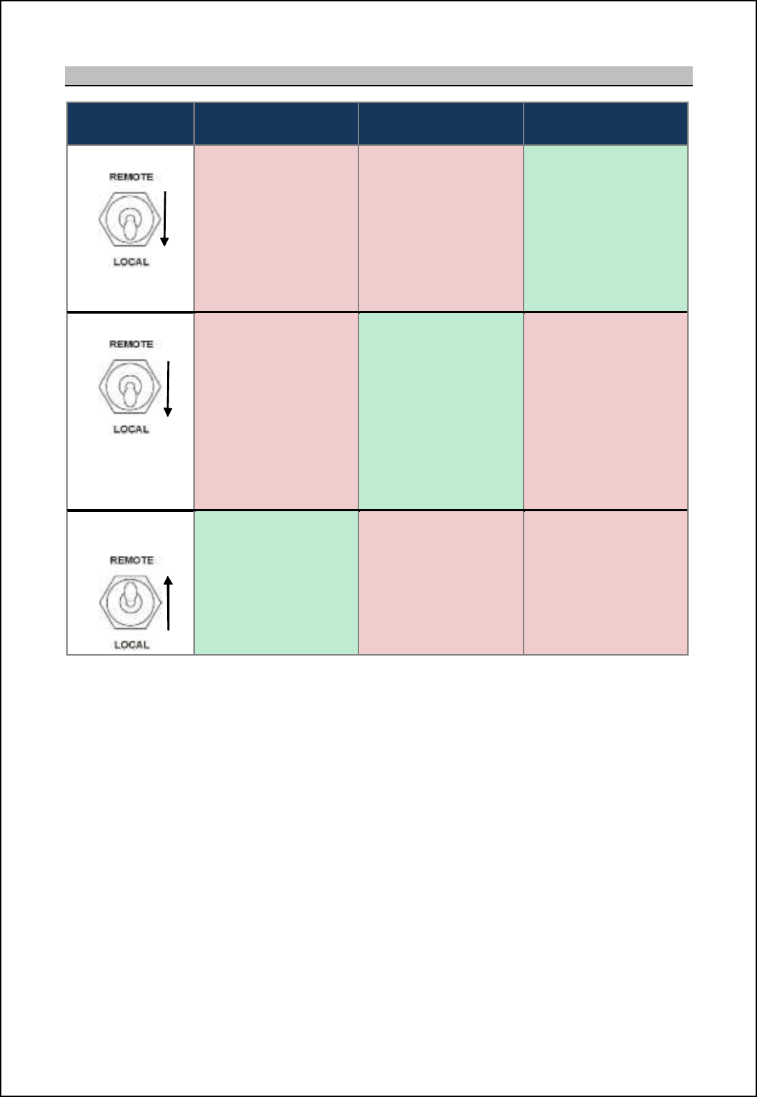
6.2.3 System control status
System
status Remote control RDU
Local control Service display
Local control
RDU set to Local
Service display
On-line
Remote control not
possible Local control at the
RDU is not possible.
The service display
has control of the
system.
RDU set to Local
Service display
Off-line,
Disconnected or
Switched OFF
Remote control not
possible
In local mode, the
RDU controls the
system using the
controls on the front
of the unit.
The service display has
no control.
RDU set to
Remote
The system is
controlled by the track
extractor
Local control at the
RDU is not possible. The service display has
no control.
SBS-900 Shore Based Radar Systems
Chapter 6: Local operation instructions
KH-1602-2 issue 1: Standard SBS900 Systems Operator & Maintenance Handbook
Page 39 of 240
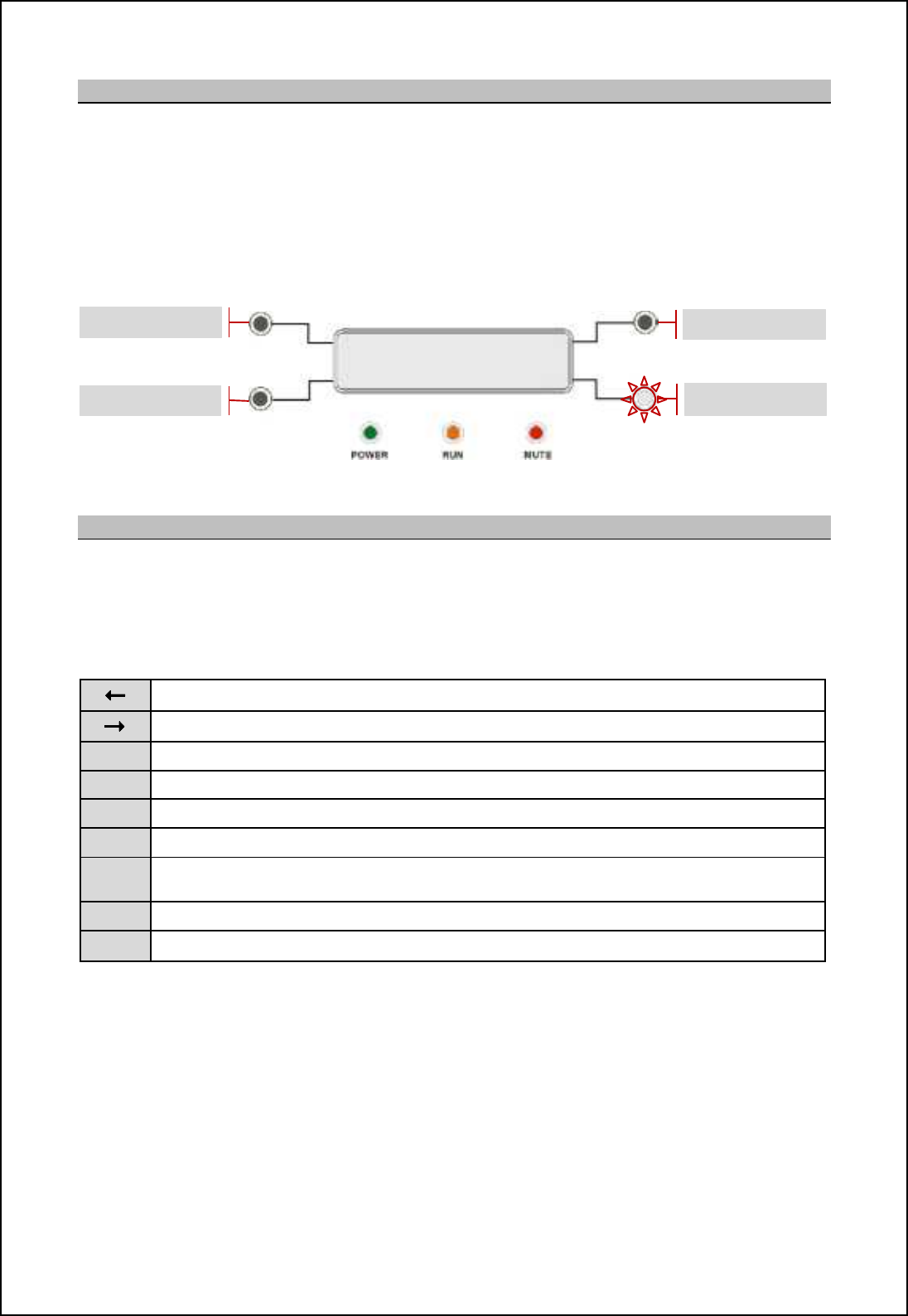
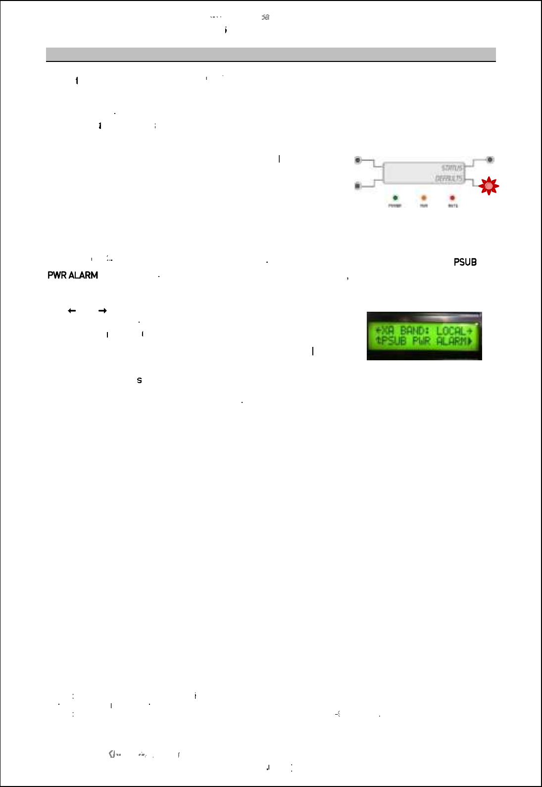
6.2.4 LCD panel operation
The LCD display on the front of the RDU is a backlit, two line, 16 character display.
Push buttons located either side of the display allow the control of the setup menus, local control and
status monitoring.
The buttons are used in association with the information displayed in the LCD panel.
The bottom right button contains a warning lamp which flashes when an alarm condition is present.
6.2.5 LCD display button functions
The display menus and functions are controlled using the four push buttons located around the LCD
display.
Adjustment & selection of the various menu functions depend on the symbol adjacent to each button
as shown below:
Select menu item to the left, usually associated with the top left button.
Select menu item to the right, usually associated with the top right button.
%Go to previous level menu, usually associated with the bottom left button.
&Go to next level menu, usually associated with the bottom right button.
,Select the option to the left, usually associated with the bottom left button.
+Select the option to the right, usually associated with the bottom right button.
#
)
Move the current cursor position to the right, usually associated with the bottom left
button.
+Increase the current items value.
-Decrease the current items value.
Top right button
Bottom right button
Top left button
Bottom left button
SBS
-
900 Shore
Ba
Ba
sed
Radar Systems
Chapter
6
:
Local operation instructions
KH
KH
-
1602 2
issue 1
:
Standard SBS900 Systems Operator & Maintenance Handbook
Page
40
40
of
240
6.2.6
Alarms
When
the system is in
Local
control
Note
1
and
an alarm
condition exists, the lower right button will flash
red and an audible alarm will be generated.
View alarm condition:
To view the alarm message/ condition,
select the
S
tatus
menu
and the alarm condition(s) will be
displayed in the lower section of the LCD display.
Where present, the
,
symbol against
the lower right
button
indicates that additional alarm conditions exist. Pressing the
,
button scrolls through any additional alarm
messages.
Silence the audible alarm:
To silence the alarm, select the
Status
menu and then press the lower right hand (red/ flashing) button.
The
audible
alarm will be silenced but the message will continue to
display until the condition is cleared.
Example
Note
2
:
In the example shown below, an X
-
band transceiver
is in
Local
control with a
displayed indicating that the AC mains input B has failed
, is switched OFF or there is a
fault with the power supply.
The
and
arrows allow navigation away from the alarm
messages to other functions available within the Status menu (see
section
6.6.4
pages 56
56
onwards).
Additional alarms conditions are present as indicated by the
,
symbol.
The
%
symbol return
s the display to the main menu.
Example of system status
with active alarms
When an
alarm has been acknowledged and more than one alarm condition exists, the display
automatically scrolls through the list of alarms.
Note
1
:
When the
Radar Distribution Unit
is set to
Remote
, alarm messages are still generated and displayed but the audible
alarm and flashing
warning
LED is disabled.
Note
2
:
The alarm shown is an
example
and
may not be a valid alarm for the SBS
900
system
.
SBS-900 Shore Based Radar Systems
Chapter 6: Local operation instructions
KH-1602-2 issue 1: Standard SBS900 Systems Operator & Maintenance Handbook
Page 41 of 240
6.3 Switch ON, OFF & Emergency stop
6.3.1 Switch ON
Prior to switching the system ON the following must be checked:
First time switch ON: Ensure the setting to work/ commissioning of the system has been
successfully completed and signed off.
Power: Check that all sources of external AC power are available and are switched
ON.
Antenna: Ensure the antenna is clear of all obstructions and that it is safe to rotate.
Transmission: Ensure it is safe to transmit.
ANTENNA ROTATION SAFETY NOTICE:
When three-phase power is connected to the system and switched ON, the antenna will
rotate immediately regardless of the RUN command status.
The following describes the local switch-ON sequence for the SBS-900 transmission systems only
and does not include the switch on procedures for the track extractor or optional service display.
DTX-A7
Transceiver
enclosure
Ensure that the AC breaker(s) located within the
transceiver enclosure are in the ON position. Note
Note: In normal operation, this switch would be left in the ON position
as it is only used/ switched OFF for maintenance purposes.
Safety
Switches
Man Aloft Switch Ensure that the externally
mounted Man Aloft Switch (MAS)
is in the FREE position. Man Aloft Switch
Radar Distribution
Unit
Ensure that the Antenna
Rotation keyswitch on the front
of the Radar Distribution Unit is
in the FREE position. Keyswitch on door of RDU
Radar
Distribution
Unit
AC power
Within the Radar Distribution Unit KDCm qcff cffogch[n_ ih
each breaker indicating that AC mains inputs are present
within the system. Note
Place all RDU breakers into the ON (UP) position.
Antenna Rotation Warnng: When three phase AC mains
is present and the breakers are in the ON position, the
Radar Distribution Unit is switched ON and the antenna will
rotate (see warnings in section 6.1 page 35). RDU AC breakers
System
available for
use
When power is available, switched ON and the switches set as shown above, the
system is available for use and the antenna will rotate.
Note: The LED indicators located on power breakers are an indication that mains voltages are present. They are NOT an
indication that the breakers are switched ON.
SBS-900 Shore Based Radar Systems
Chapter 6: Local operation instructions
KH-1602-2 issue 1: Standard SBS900 Systems Operator & Maintenance Handbook
Page 42 of 240
6.3.2 Switch OFF
Switch OFF: The following describes how to switch OFF the SBS-900 system for operation purposes.
The following does not include the switch OFF/ shut down procedures for the track extractor, optional
service display or external equipment attached to the system.
System isolation: Please refer to the maintenance section of the system handbook (KH-1602-2) for
details on isolating the system from the mains supplies for maintenance purposes or working aloft.
Caution
The following details switching the SBS-900 system OFF for operation purposes only.
The following must not be used as a primary means of system isolation for maintenance
procedures or working aloft.
Radar
Distribution
Unit
Safety
Switches
Place the Antenna Rotation keyswitch on the front of
the Radar Distribution Unit into the OFF position.
This removes all AC power to the DTX-A7
Transceiver Enclosue and the Antenna sub-system
As an additional safety precaution, when in the OFF
position the key can be removed. Keyswitch on door of RDU
Radar
Distribution
Unit
AC power
Place all three breakers within the Radar Distribution Unit to the OFF position.
System status:
- The Radar Distribution Unit is switched OFF but is not isolated from the AC
input supplies.
- The DTX-A7 Transceiver Enclosure is switched OFF thus stopping any
transmission.
- The antenna sub-system is switched OFF and will not rotate.
The LED indicators on the breakers remain illuminated. Note
Note: The LED indicators located on power breakers are an indication that mains voltages are present. They are NOT an
indication that the breakers are switched ON.
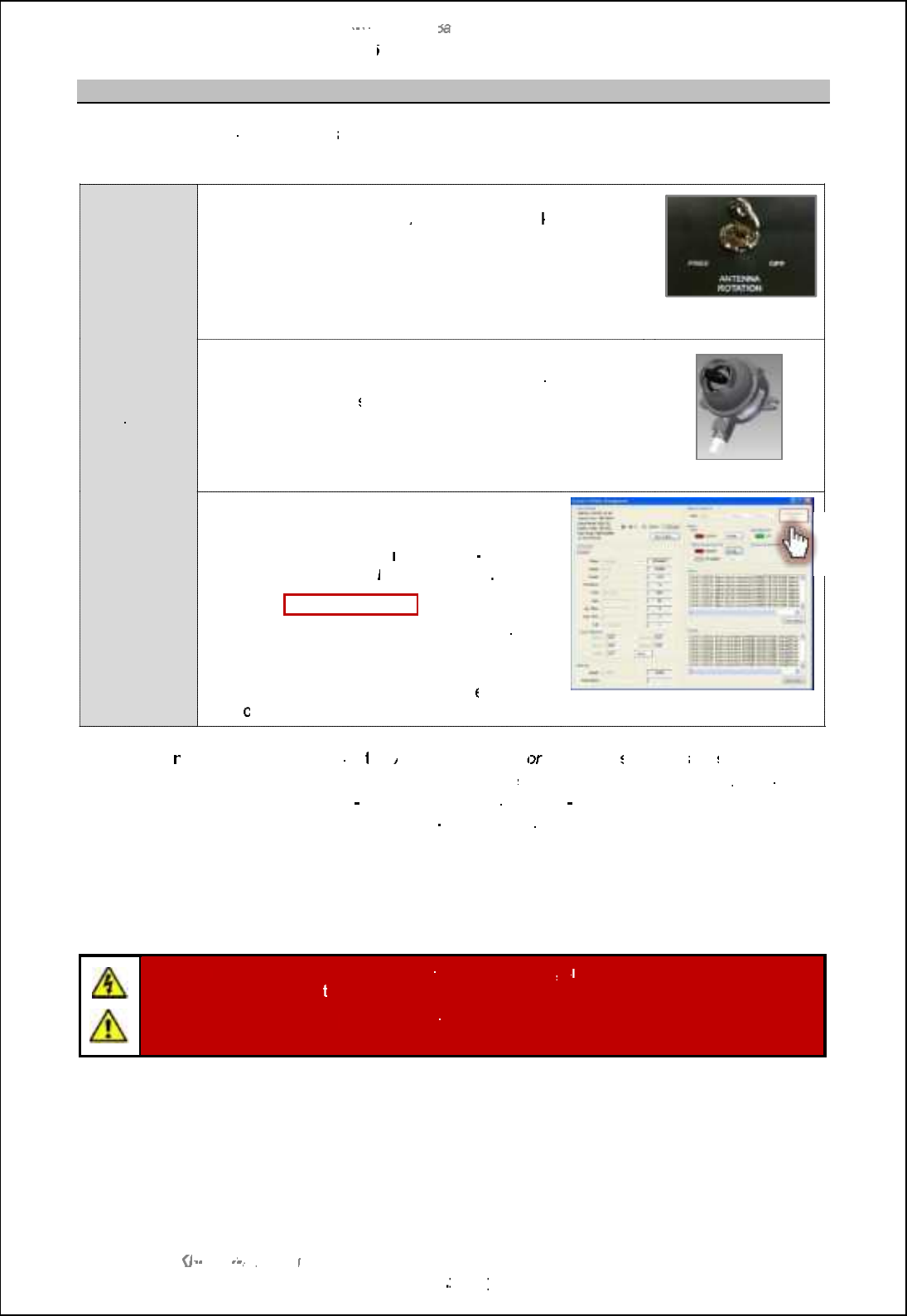
SBS
-
900 Shore
Ba
Ba
sed
Radar Systems
Chapter
6
:
Local operation instructions
KH
KH
-
1602 2
issue 1
:
Standard SBS900 Systems Operator & Maintenance Handbook
Page
43
43
of
240
6.3.3
Emergency
antenna
stop
In an emergency,
antenna rotation
and
system
transmission can be stopped using
ANY of the
following mechanisms.
STOP
antenna
rotation
Use
any
of the
functions
shown
RDU keyswitch:
Place the
Antenna Rotation
keyswitch
on the front of the
Radar Distribution Unit
into the
OFF
position.
As an additional safety precaution, when in
the OFF
position the key can be removed.
Keyswitch on door of
RDU
Man Aloft Switch (MAS):
P
lace the
externally mounted
masthead
Man Aloft
switch to the OFF position.
This has the same effect as using the
Antenna Rotation
switch noted above.
Man
aloft switch
Service Display:
RadarView
software
When the system is being operated via the
service display
(software
must be
On
On
-
line)
,
select
Channel A
then
Manage Radar
Select the
Emergency
Stop
button.
This has the same effect as using the
Antenna
Rotation Keyswitch or the Man Aloft switch.
Caution: This function is disabled wh
en the
Servi
ce Display is Off
-
line.
Example of Manage Radar window
in RadarView
program
What happe
ns?
When
the
Antenna Rotation
or
or
Man Aloft
switches
are
set to OFF
or
when
the
Emergency Stop
software function is activated
, single and
three
phase AC power to the
DTX
-
A7
A7
transceiver
enclosure
and
to
the
Antenna sub
-
assembly
are isolated thus stopping antenna
rotatation and RF transmission.
System isolation:
Please refer to the maintenance section for details on isolating the
system from the
AC
mains supplies for maintenance purposes or
working aloft.
Caution
:
When the emergency stop functions are used
,
s
ingle and three phase AC
voltages are still presen
t within the RDU.
The following
procedures
must not be used as a primary means of system isolation for
maintenance procedures or working aloft.

SBS-900 Shore Based Radar Systems
Chapter 6: Local operation instructions
KH-1602-2 issue 1: Standard SBS900 Systems Operator & Maintenance Handbook
Page 44 of 240
6.4 Local control operational states
For the purposes of the following explanations, track extractor g_[hm nb_ om_lm ]igg[h^ [h^
display system or track extractor.
System
OFF
System
configuration
'Single and three-phase AC supplies to the RDU are available.
'Breakers within RDU are OFF.
'Antenna Rotation keyswitch & Man aloft switch both set to OFF.
'Remote/ Local &standby/ RUN switches on the RDU set to Remote &
standby.
'No commands being received from the Service Display.
System status
'AC power is present within the RDU but as the breakers are in the OFF
position, the dual redundant power supply is OFF and no DC rails are
being generated.
The Radar Distribution Unit is OFF.
'Single and three-phase mains voltages are NOT sent to the transceiver /
gearbox.
System
RUN
Safety
switches
OFF
System
configuration
'Single and three-phase AC supplies to the RDU are switched ON.
'The AC Breakers within RDU are ON.
'Antenna Rotation keyswitch OR Man Aloft switch set to OFF.
'Remote/ Local &standby/ RUN switches on the RDU set to Local &
Standby.
System status
'The RDU detects that the Antenna Rotation keyswitch OR Man Aloft
switches are in the OFF position. This breaks the safety switch current loop.
'The single and three-phase relays are opened and AC power to the
transceiver/ gearbox is switched OFF.
'Antenna rotation and transmission is not possible
'The Service Display has no control over the system.
System
standby
System
configuration
'Single and three-phase AC supplies to the RDU are available.
'The AC Breakers within RDU are ON.
'Antenna Rotation keyswitch & Man Aloft switch both set to FREE.
'Remote/ Local &standby/ RUN switches on the RDU set to Local &
Standby.
System status
'The RDU is switched ON. The software reads the condition of the Antenna
Rotation keyswitch and Man Aloft switch, detects these are in the FREE
position so makes relays within the breakers sending AC power to the
transceiver/ gearbox.
'The antenna commences rotation regardless of the RUN command
State. Note
'The SharpEye transceiver switches ON and after a 30 to 40 second warm-
up time enters a standby state waiting for a RUN command from the RDU.
'System and BITE data from both the RDU and transceiver is available.
'The system is now in standby waiting commands from the Service Display.
System
RUN
System
configuration
'Single and three-phase AC supplies to the RDU are switched ON.
'The AC Breakers within RDU are ON.
'Antenna Rotation keyswitch & Man Aloft switch both set to FREE.
'Remote/ Local &standby/ RUN switches on the RDU set to Local & RUN.
System status
'The RDU detects that the RDU switches are set to Local and RUN.
'The RUN command is sent to the transceiver which commences
transmitting.
'Radar signals, ACP, ARP and heading line data is sent to the radar I/O
module within the RDU.
Note: Antenna rotation can be over-ridden in the Control Defaults menu.

SBS-900 Shore Based Radar Systems
Chapter 6: Local operation instructions
KH-1602-2 issue 1: Standard SBS900 Systems Operator & Maintenance Handbook
Page 45 of 240
Transceiver operational states
The following table shows the various operation states of the X or S-band SharpEyeTM transceivers
within the DTX-A7 transceiver enclosure:
Operation state Description
OFF Power is not applied to the transceiver and it is switched OFF.
Initialise
On completion of initialisation the transceiver switches to standby or, if any of
the self-test checks fail, to fault state.
The system initialisation typically takes 30 to 40 seconds after which time the
system becomes available for operation.
Standby
In standby the transceiver establishes communication with the Radar
Distribution Unit and reports its status.
The transceiver receives and acts on commands from the RDU.
In Standby the antenna rotates but the system does not transmit.
Transmit
When a RUN command is received from the Radar Distribution Unit and
azimuth and heading line signals are present, the SharpEyeTM transmits.
The transceiver initially outputs at low power. The radar returns are then
processed enabling the VSWR to be checked without the risk of damage to the
transceiver.
If the VSWR is within limits then the transceiver automatically switches to full
power.
If the VSWR is high, indicating an antenna fault, a warning message is sent to
the Radar Distribution Unit and the transceiver enters the degraded Low
Power state.
Degraded
(Low power)
The transceiver continuously runs background performance checks on forward
power, reverse power, receiver sensitivity and temperature. If any of these
parameters falls outside predetermined levels a warning message is sent to
the Radar Distribution Unit indicating the nature of the fault.
The transceiver continues to operate, but with reduced performance and
functionality.
Fault
If the performance or functionality is degraded such that the transceiver cannot
operate it enters the fault state and a fault message is sent to the display
equipment.
The transceiver stops radiating RF and there is no video output to the Radar
Distribution Unit.
A spurious fault may be cleared by re-powering the equipment.
Communication
error
If communication is lost between the Radar Distribution Unit and the
SharpEyeTM, the RDU reboots the SharpEye leading to a potential 60 second
gap in coverage.
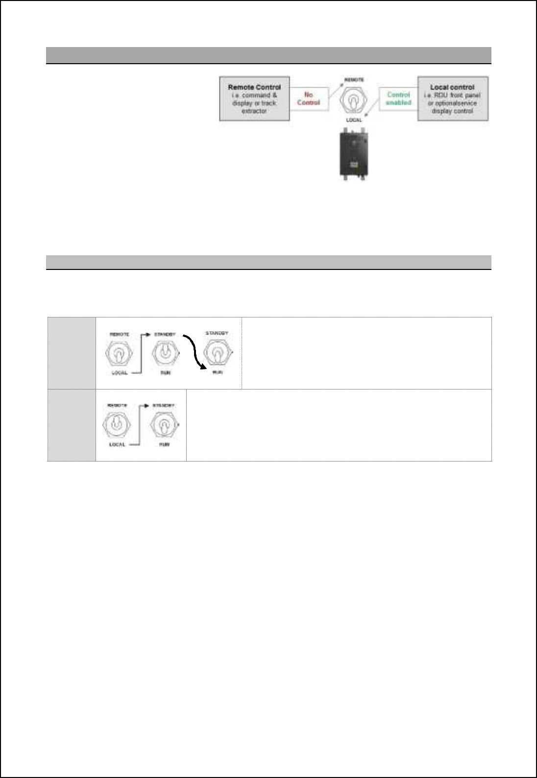
SBS-900 Shore Based Radar Systems
Chapter 6: Local operation instructions
KH-1602-2 issue 1: Standard SBS900 Systems Operator & Maintenance Handbook
Page 46 of 240
6.5 Switch from Local to Remote
When Local control is no longer
required, the system MUST be
switched to Remote.
Caution: If the system is left in Local
mode, remote operation by the
command & display system or Track
Extractor will NOT BE POSSIBLE.
Changeover: The system can only be changed from Local to Remote control using the switch on the
Radar Distribution Unit; it is not possible to remotely change from Local to Remote.
6.5.1 Set to RUN & switch to Remote
The system can be set to Remote before the track extractor is on-line or ready (see below), this may
be desirable when handing the system back to the Remote operating station.
Local
selected
With Local selected use the front panel or service
display to place the transceiver into RUN.
Ensure the system is transmitting and is configured as
required for operation.
Switch
to
Remote
Switch from Local to Remote.
The system continues to transmit and is ready to accept control
commands from the command & display system or track extractor.
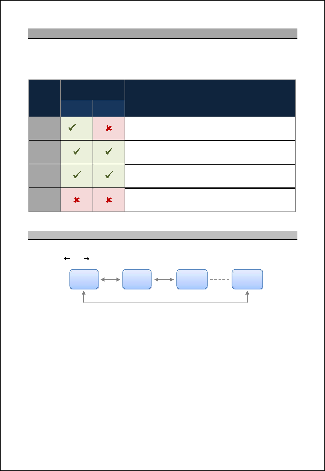
SBS-900 Shore Based Radar Systems
Chapter 6: Local operation instructions
KH-1602-2 issue 1: Standard SBS900 Systems Operator & Maintenance Handbook
Page 47 of 240
6.6 Menus
There are four menus that can be selected from the RDU LCD display.
Menu availability depending on the position of the RDU Local & Remote switch settings as detailed
below:
Menu
RDU Menu
availability
Description
Local
control Remote
Control
Control
menu Note
This menu contains the operator and maintainer adjustable
parameters for the system such as range mode,Mute ON/
OFF,sea and rain filters etc.
Status
menu
The current status of the system can be viewed but not
adjusted. For example signal status, transceiver run-time and
temperature figures etc.
Default
menu The setup/ configuration of the system can be viewed but not
adjusted.
Setup
menu
Sb_ R_noj g_ho cm hin [p[cf[\f_ il l_kocl_^ `il hilg[f
system operation. The menu is used by the system maintainer
or commissioning engineer to configure the system.
6.6.1 Navigating within menus
Within all RDU menu structures it is possible to move back and forward between menus
using the left and right buttons located to the side of the LCD front panel:
Note: In local control, the optional service display must be •iff-lineto obtain the Control Menu.
Range
mode
TX
power
TX
frequency Exit

SBS-900 Shore Based Radar Systems
Chapter 6: Local operation instructions
KH-1602-2 issue 1: Standard SBS900 Systems Operator & Maintenance Handbook
Page 48 of 240
Page intentionally blank
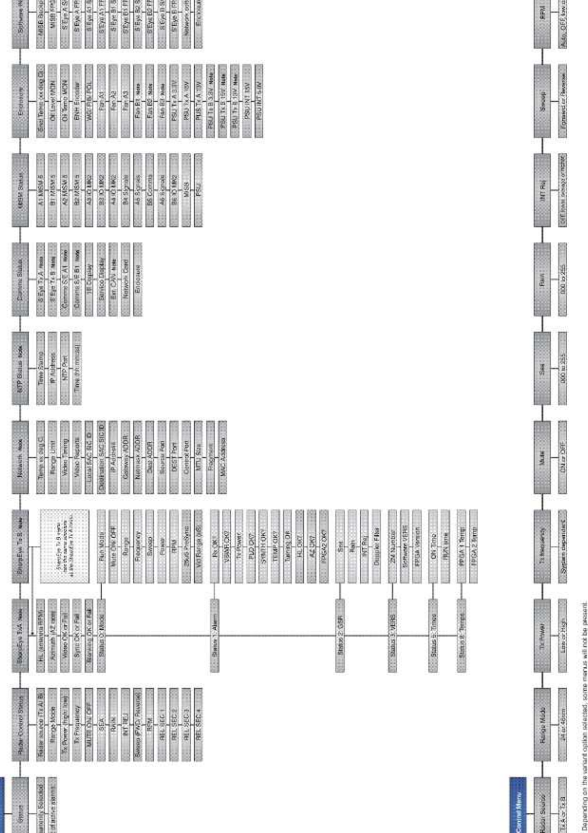
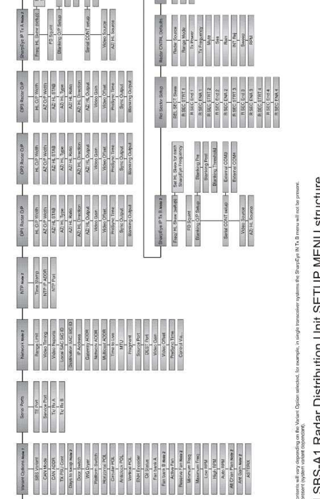
is not available in normal operation and
can
only be accessed
by authorised engineers
who
commission
or maintain
the system.
There are NO operator functions within the Setup menu.
Incorrect adjustment of values
within the Setup menu can reduce transceiver performance, disable functionality and/ or render the system un-operational.
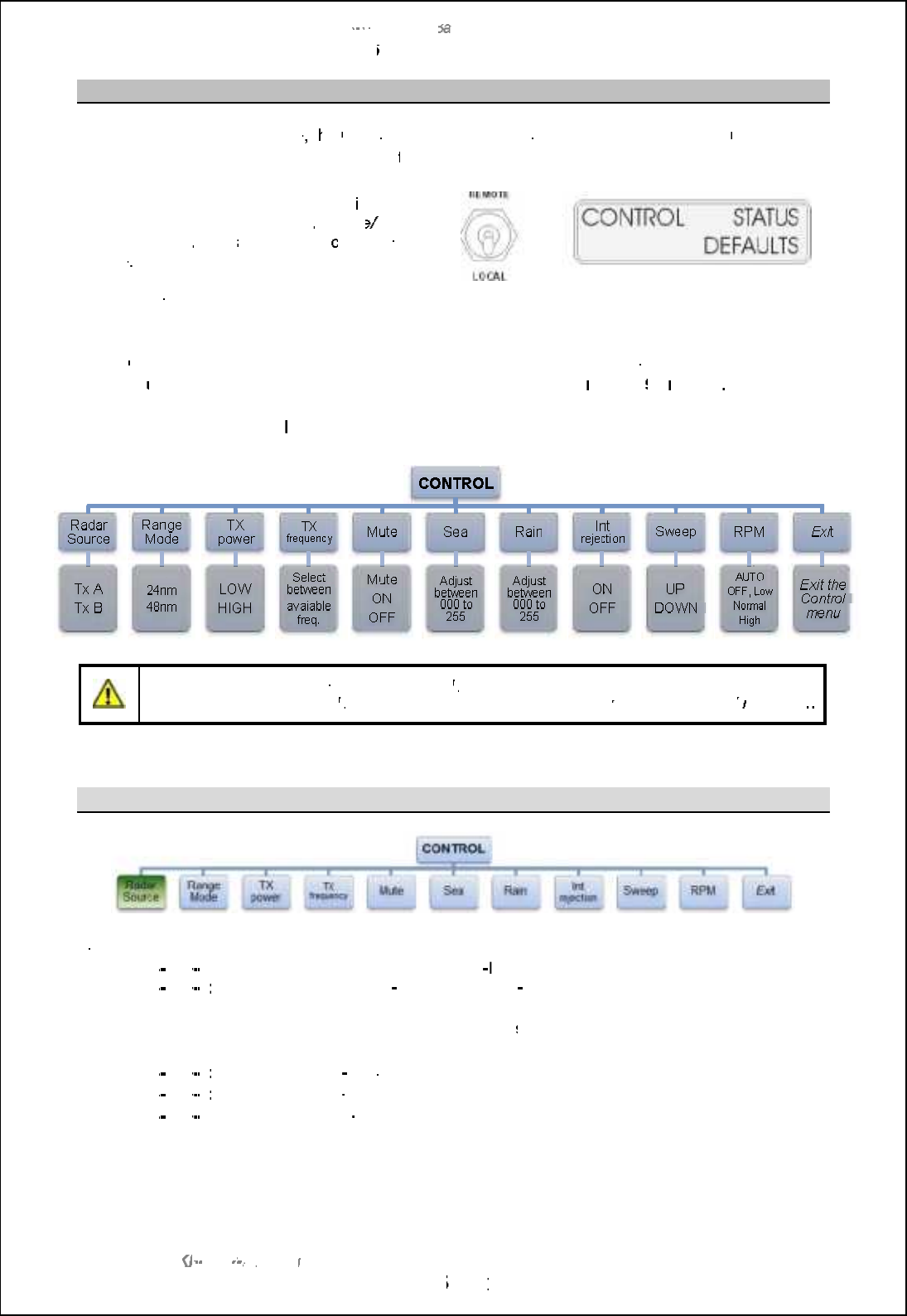
SBS
-
900 Shore
Ba
Ba
sed
Radar Systems
Chapter
6
:
Local operation instructions
KH
KH
-
1602 2
issue 1
:
Standard SBS900 Systems Operator & Maintenance Handbook
Page
51
51
of
240
6.6.3
Control menu
When operat
ing in Local mode
, t
he
C
ontrol menu
on the
Radar Distribution Unit
can be
used by the
operator or the system
maintainer
to
to
adjust
the system settings.
Menu availability:
The
control menu
is only
available on the RDU when the
Remote
/
Local
switch is set to
Local
and the servi
ce display is
off
-
line
, is not connected or is switched OFF.
When Remote is selected, the control menu is
not available.
When
Control
is selected from the front panel, the various functions shown
below
can be selected and
adjusted
using the LCD display buttons as
described in section
6.2.4
pages 39
39
o
nwards
.
There is no
Save Changes
button or function, any adjustments are immediately adopted.
Caution:
Incorrect configuration in the
Control
menus can degrade the performance of the system or
inhibit operation. The
Control
menus should only be used by a
suitably
trained technician/
maintainer
6.6.3.1
Radar Source
Dual Systems:
In dual transceiver systems, radar source selects the transceiver to be used.
-
SBS
-
900
-
3:
Select between Tx A or Tx B (both x
band)
-
SBS
-
900
-
4:
4:
Select between Tx A (X
-
band) or Tx B (S
band)
Single system:
The radar Source menu has no function in
single transceiver system
s, the TX is
automatically selected and cannot be changed.
-
SBS
-
900
-
1:
1:
TX A
selected (X
band)
-
SBS
-
900
-
2:
2:
TX A selected (X
-
band)
-
SBS
-
900
-
51:
TX B selected (S
-
band)
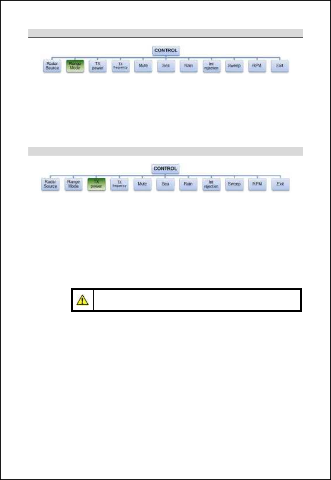
SBS-900 Shore Based Radar Systems
Chapter 6: Local operation instructions
KH-1602-2 issue 1: Standard SBS900 Systems Operator & Maintenance Handbook
Page 52 of 240
6.6.3.2 Range Mode
Within the Range mode menu, the transceiver instrument range can be selected between 24 and
48nm.
24nm: Limits the transceiver to an instrumented range of 24nm. This offers twice the range
discrimination of the 48nm range.
48nm: Limits the transceiver to an instrumented range of 48nm.
6.6.3.3 TX Power
The output power of the SharpEyeTM transceiver can be switched between High (default) and Low.
High power: The SharpEyeTM transceiver transmits at full power.
This is the recommended default setting.
Low power: Low power is used in close waters or in a high clutter environment where a high
output power may produce excessive unwanted reflections from buildings, bridges
and vessels.
The transceiver will utilise the standard frame pattern but with output power reduced
to less than 40W.
Caution: As a result of reduced output power, range performance will be reduced
and the system may not meet the expected operational detection performance.
When low power is selected, a low power status is automatically generated to advise
the operator that the system is operating at a reduced output power.
Where the SharpEyeTM detects a VSWR or a high temperature within the transceiver
the system automatically switches to low power mode and generates system alarms.
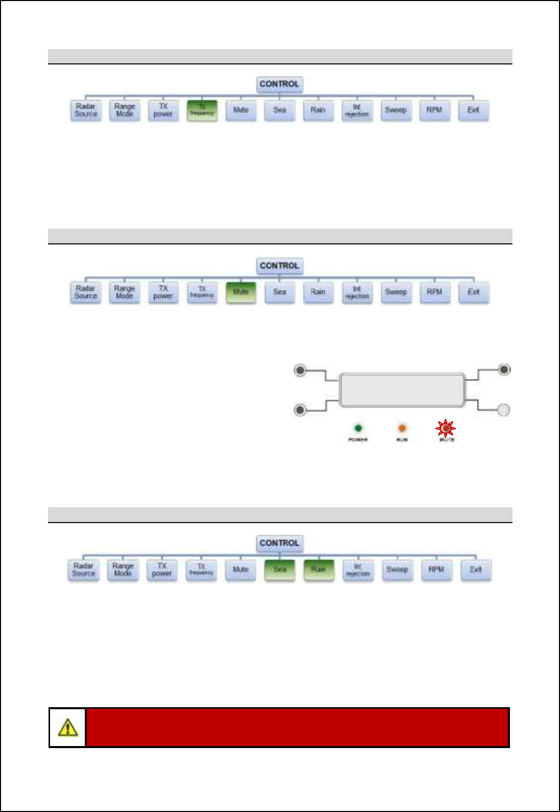
SBS-900 Shore Based Radar Systems
Chapter 6: Local operation instructions
KH-1602-2 issue 1: Standard SBS900 Systems Operator & Maintenance Handbook
Page 53 of 240
6.6.3.4 TX Frequency
The frequency of the SharpEyeTM transceiver can be selected which may be necessary to reduce
interference from other transceivers to obtain the best picture quality.
Seven frequency bands are available between 9.21and 9.49GHz, each band being 20MHz wide and
each band being separated by 20MHz.
6.6.3.5 Mute
The Mute function allows a 360 degree transmission inhibit to be enabled/ disabled.
Mute ON: Transmission is muted/ stopped i.e.
no RF is radiated from the antenna
however the antenna continues to
rotate.
The RED Mute LED on the front of
the RDU illuminates.
Mute OFF: The system transmits fully for 360
degrees.
The RED Mute LED on the front of is
OFF.
Mute LED illuminates when Mute is enabled
6.6.3.6 Sea & rain
The level of Sea and Rain filtering can be adjusted between 000 (minimum) to 255 (maximum).
Sea: Filters the effect of sea clutter on returns.
Rain: Filters the effect of rain clutter on returns.
The levels are set using the +(decrease value) and ,(increase value) buttons to produce the best
quality picture in the prevailing conditions.
Caution: Care should be exercised when adjusting Sea and Rain filters as reducing the
filter level can reduce signal returns from wanted / actual targets.
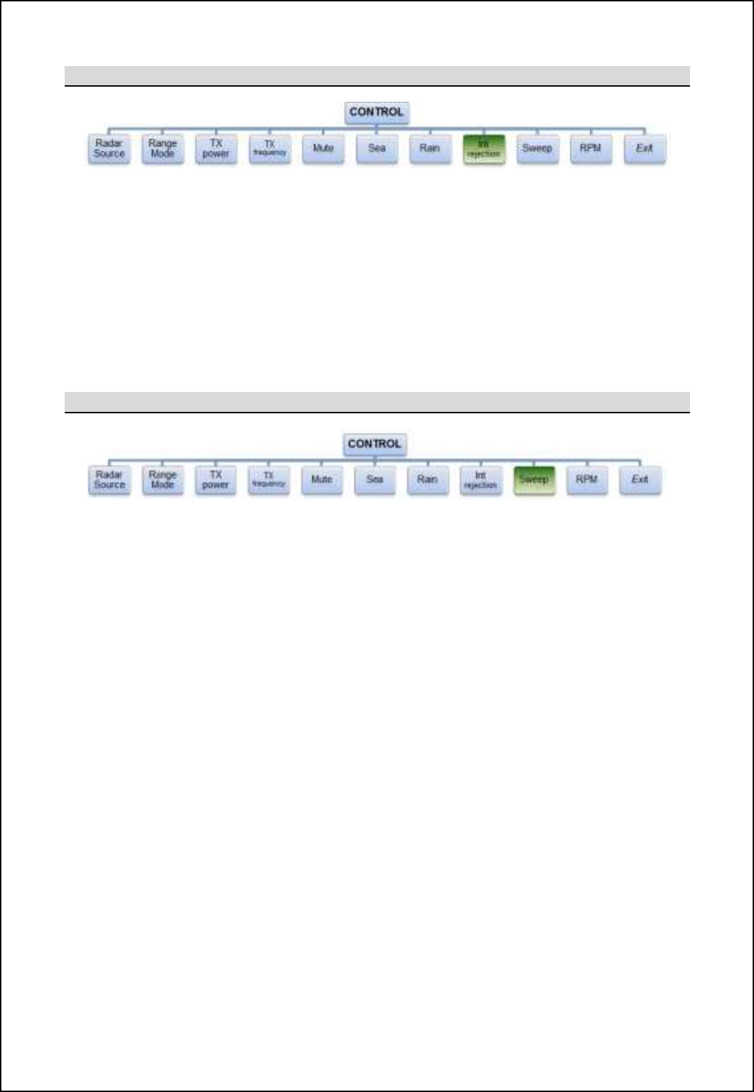
SBS-900 Shore Based Radar Systems
Chapter 6: Local operation instructions
KH-1602-2 issue 1: Standard SBS900 Systems Operator & Maintenance Handbook
Page 54 of 240
6.6.3.7 Int. Rejection
The Int. Rejection (Interference Rejection) filtering reduces the effect of in-band asynchronous
interference from other radars thus reducing clutter on screen.
Int. Rejection can be enabled, disabled and configured as shown below. Note
OFF: Interference rejection OFF/ disabled.
Lower: Select lower of adjacent traces.
Higher: Selects higher of adjacent traces. Note
Average: Selects the average of adjacent traces. Note
6.6.3.8 Sweep
Sweep sets the signal sweep direction of the SharpEyeTM transceiver RF pulses during medium and
long pulse transmissions only.
Sweep UP: Default setting.
Sweep DOWN: This reverses the sequence of the RF pulses and may assist in the reduction
of in-band asynchronous interference from other radars in the same Locality
thus potentially improving the quality of returns.
Note: Higher and Average interference rejection modes cannot be selected, these are for future developments
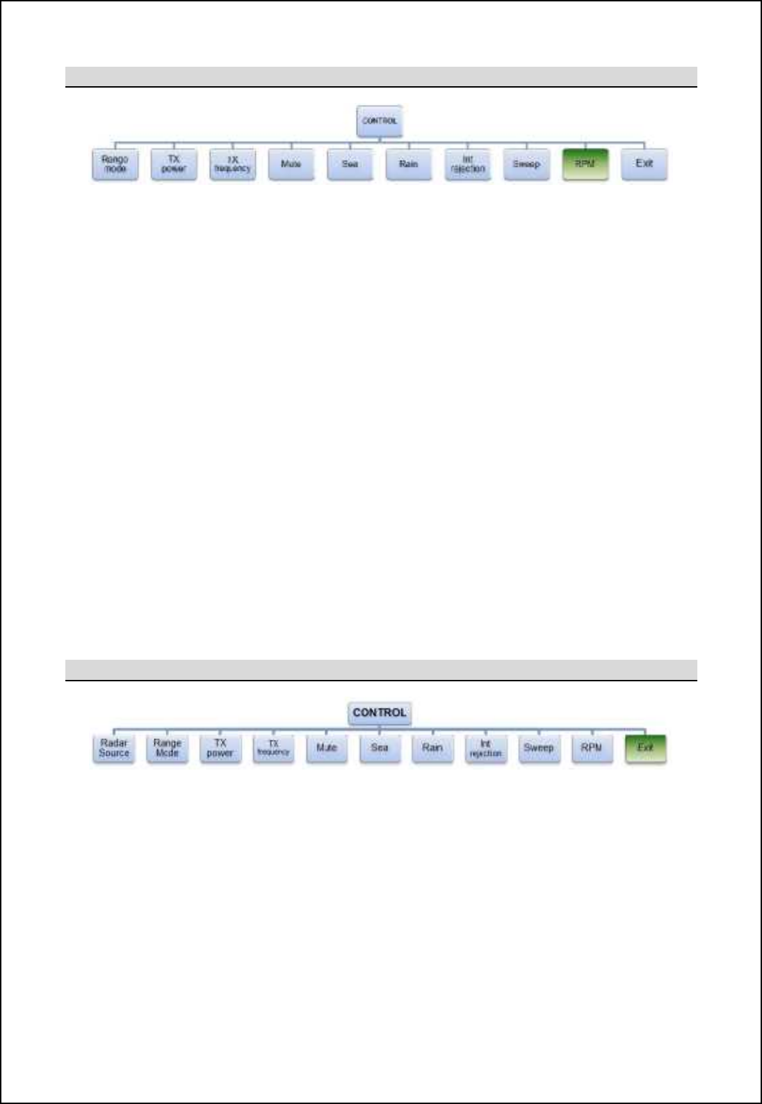
SBS-900 Shore Based Radar Systems
Chapter 6: Local operation instructions
KH-1602-2 issue 1: Standard SBS900 Systems Operator & Maintenance Handbook
Page 55 of 240
6.6.3.9 RPM
The RPM function allows the operator to stop rotation (OFF), select auto or one of three pre-defined
antenna rotation speed. Note 1
- Antenna speeds are configured at the factory and are enabled or disabled during setting to work.
- The RPM value set by selecting low, normal and high cannot be configured by the operator.
- Depending on the system configuration, different antenna speeds may not be available.
Auto: Automatically selects the optimum antenna RPM for the range mode in use. Note 1
OFF: Antenna rotation is stopped. Note 2
Low: Where enabled, the low antenna rotation speed configured during setting to work can
be selected.
-Low speeds increase the probability of target detection whilst reducing the update
rate.
Normal: The standard antenna rotation speed configured during setting to work can be
selected.
-Normal speed offers the best overall detection performance.
High: Where enabled, the high antenna rotation speed configured during setting to work
can be selected.
-High speeds increase the update rate whilst reducing the probability of detection.
6.6.3.10 Exit control menu
Selecting Exit closes the Control menu and returns the display to the default menu.
There is no Save Changes button or function, any adjustments are immediately adopted.
Note 1: Antenna speed selection is system dependant and is not available on all models. Please consult with Kelvin Hughes
for additional details.
Note 2: Setting the antenna speed to OFF in the RPM menu must NOT be used as a primary means of isolating the antenna
and its sub-systems for safety critical purposes.
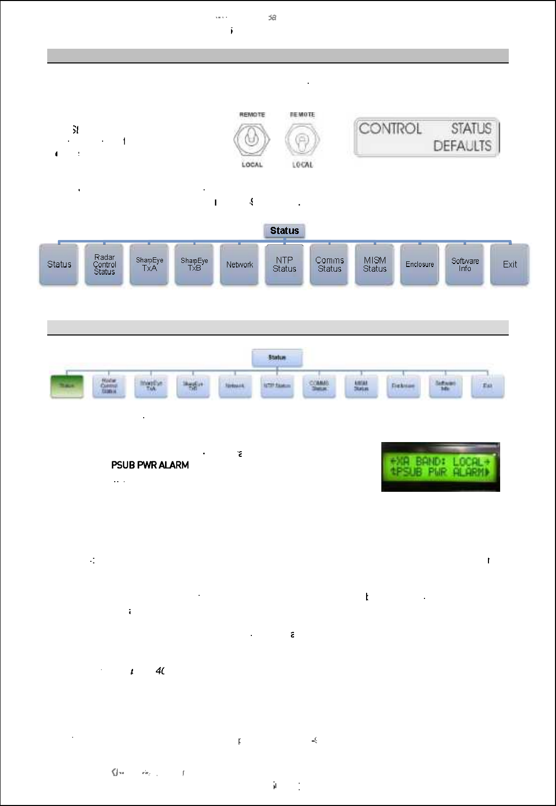
SBS
-
900 Shore
Ba
Ba
sed
Radar Systems
Chapter
6
:
Local operation instructions
KH
KH
-
1602 2
issue 1
:
Standard SBS900 Systems Operator & Maintenance Handbook
Page
56
56
of
240
6.6.4
Status menu
The
Status menu
on the
Radar Distribution Unit
is used by the
operator or the system
maintainer
to
view
but not configure or adjust
the current system settings.
The
S
tatus
menu
is available on
the RDU
in both
the
R
emote
and
L
ocal
setting.
or
When
Status
is selected from the front panel, the various functions shown below can be selected and
viewed
as described in section
6.2.4
pages
39
39
onwards
6.6.4.1
System status
When the status menu is initially selected the system status is shown
with any active alarms.
In the example shown below, an X
-
band tr
ansceiver is in
Local
control with a
displayed indicating that the AC
mains input B has failed, is switched OFF or there is a fault with the
power supply.
Note
The
,
symbol against
the lower right
button indicates that additional
alarm conditions exist. Pressing the
,
button scrolls through these
alarms.
Example of system status
with active alarms
ALARMS
: When an alarm condition exists, the lower right button will flash red and an audible alar
m
will sound.
To silence the alarm, select the
S
tatus menu and press the
lower right
button. The
audible alarm will
stop however the
alarm condition will continue to display until the condition is cleared.
Where an alarm has been acknowledged and more th
an one alarm condition exists, the display
automatically scrolls through the list of alarms.
See section
6.2.6
page 40
40
for additional information on alarms.
Note:
The alarm shown in the example may not be a
pplicable to the SBS
900 system.
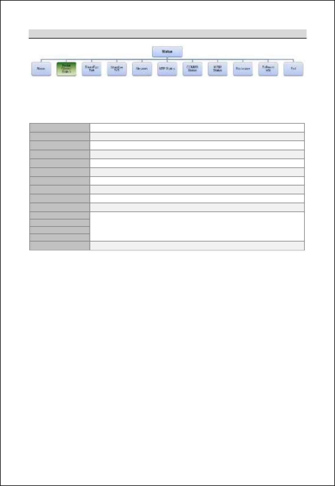
SBS-900 Shore Based Radar Systems
Chapter 6: Local operation instructions
KH-1602-2 issue 1: Standard SBS900 Systems Operator & Maintenance Handbook
Page 57 of 240
6.6.4.2 Radar Control Status
By scrolling through the Radar Control Status menus, the following system configurations and settings
can be viewed but not adjusted.
A full description of each function is shown in the Control menu section 6.6.3 pages 51 onwards.
Radar Source Transceiver A or B selection in dual systems
Range mode Current instrumented range of 24nm or 48nm.
TX power Rb[ljDs_x ionjon jiq_l i` Kiq il bcab-
TX frequency Shows which of the 7 SharpEye
TM
transmission frequencies is selected.
Mute Indicates if the Mute is switched ON or OFF.
SEA Shows the configured value of the Sea filter (000
min.
to 255
max.
).
RAIN Shows the configured value of the Rain filter (000
min.
to 255
max.
).
Int rejection Shows if interference rejection is set to OFF or Lower.
Sweep Shows if the sweep is set to Forward (default) or reverse.
RPM Shows the selected speed (revolutions per minute) of the antenna motor.
Rel sector 1
Rel sector 1 to 4 will show Enabled or Disabled for each blanking sector.
When Enabled, the start/ stop bearings of the selected sector is also shown.
Rel sector 2
Rel sector 3
Rel sector 4
Exit Exits the Radar control status menu.
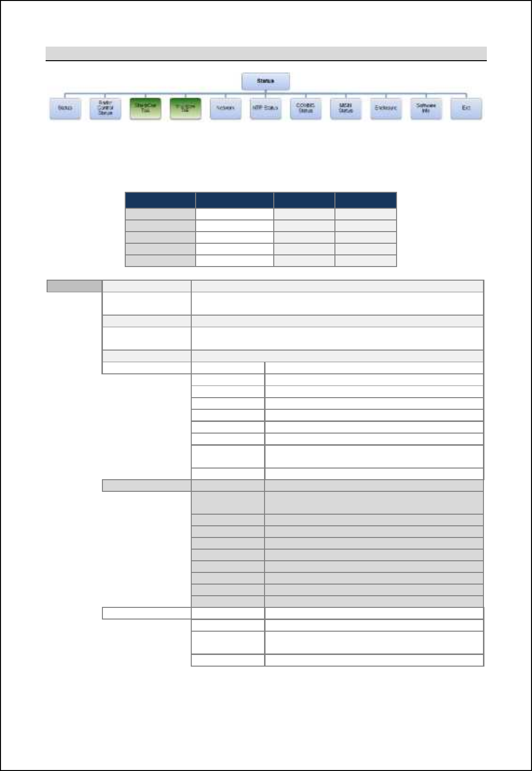
SBS-900 Shore Based Radar Systems
Chapter 6: Local operation instructions
KH-1602-2 issue 1: Standard SBS900 Systems Operator & Maintenance Handbook
Page 58 of 240
6.6.4.3 SharpEye
By scrolling through the SharpEye Tx A or SharpEye Tx B menus (see table below), the following
transceiver conditions can be viewed but cannot be adjusted.
Note: In Single transceiver systems, the Tx A or Tx B menu may not be available.
System Transceivers TX A Tx B
SBS
-
900
-
1
Single
X
-
band
N/A
SBS
-
900
-
2
Single
X
-
band
N/A
SBS
-
900
-
3
Dual
X
-
band
X
-
band
SBS
-
900
-
4
Dual
X
-
band
S
-
band
SBS
-
900
-
51
Single
N/A
S
-
band
SharpEye HL Shows the antenna RPM based on HL frequency.
Azimuth Shows the value of the azimuth being received or Fail if no signal
is
present. The normal value is 4096.
Video Shows if the video is OK (present) or Fail if no signal is present.
Sync Shows the current Sync value (PRF) or Fail if no signal is
present
.
Blanking Shows if blanking is OK (present) or Fail if no signal is present.
Status 0: Mode
&
Run Mode
Standby or Run
.
Mute ON or OFF.
Range
24nm or 48nm
.
Frequency SharpEye
TM
transmission frequency (1 to 7).
Sweep
Forward or reverse
.
Power High or Low.
RPM
Shows the
RPM as detected by the SharpEye
TM
25us Pre sync Pre-sync from the SharpEye
TM
transceiver
Enabled or Disabled.
Video range
Show the instrumented video range in
µ
s
.
Status 1: Alarm
&
RX
Receiver OK or
F
ail
.
VSWR VSWR OK or Fail ~if Fail the transceiver
automatically switches to low power mode
.
T
X power
Output power OK or
F
ail
.
PLO
Programmable
Local
oscillator OK or
F
ail
.
SYNTH
SharpEye
TM
internal synth OK or
F
ail
.
Temp
Internal temperature OK
, warning or
shutdown
.
Turning
Antenna t
urning data OK or
F
ail
.
HL
Heading line
(ARP)
OK or
F
ail
.
AZ IN
Azimuth in
(ACP)
OK
, reverse
or
F
ail
.
FPG
A2
FPGA 2 OK or
F
ail.
Status 2: GSR
&
Sea
Sea clutter: 000 (minimum) to 255 (maximum)
.
Rain Rain clutter: 000 (minimum) to 255 (maximum).
Int Rej Shows the current Interference Rejection
setting
.
Doppler filter
Select levels of 4, 8, 16, 32 or 64
.
Continued on following page
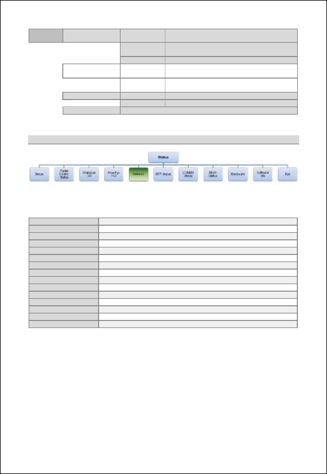
SBS-900 Shore Based Radar Systems
Chapter 6: Local operation instructions
KH-1602-2 issue 1: Standard SBS900 Systems Operator & Maintenance Handbook
Page 59 of 240
SharpEye
(
continued
)Status 3: VERS &ZM number System software identification number.
Software
VERS
The version number of the above ZM number.
FPGA version
Version of code loaded into the FPGA
.
Status 5: Times &Time-ON Number of hours the SharpEye
TM
has been
switched ON
(HH:MM)
.
Run-time Number of hours the system has been
transmitting (HH:MM).
Status 8: Temp
&
FPGA 1 temp
The current temperature of FPGA 1 (Deg. C)
.
FPGA2 temp
The current temperature of FPGA 2 (Deg. C)
.
Exit
Exit the SharpEye Tx A or Tx B menu
6.6.4.4 Network
The IP addresses and network status can be viewed but not adjusted.
Note: In some configurations, the menu will not be present.
Temp
Shows the temperature in Degrees C.
Range Limit
TBC
Video Timing
TBC
Video reports
TBC
Local SAC SIC ID
TBC
Destination SAC SIC ID
TBC
IP Address
TBC
Gateway Address
TBC
Netmask Address TBC
Dest Address
TBC
Control Port TBC
MTU size
TBC
Fragment TBC
MAC Address
TBC
Exit Exit the Network menu.
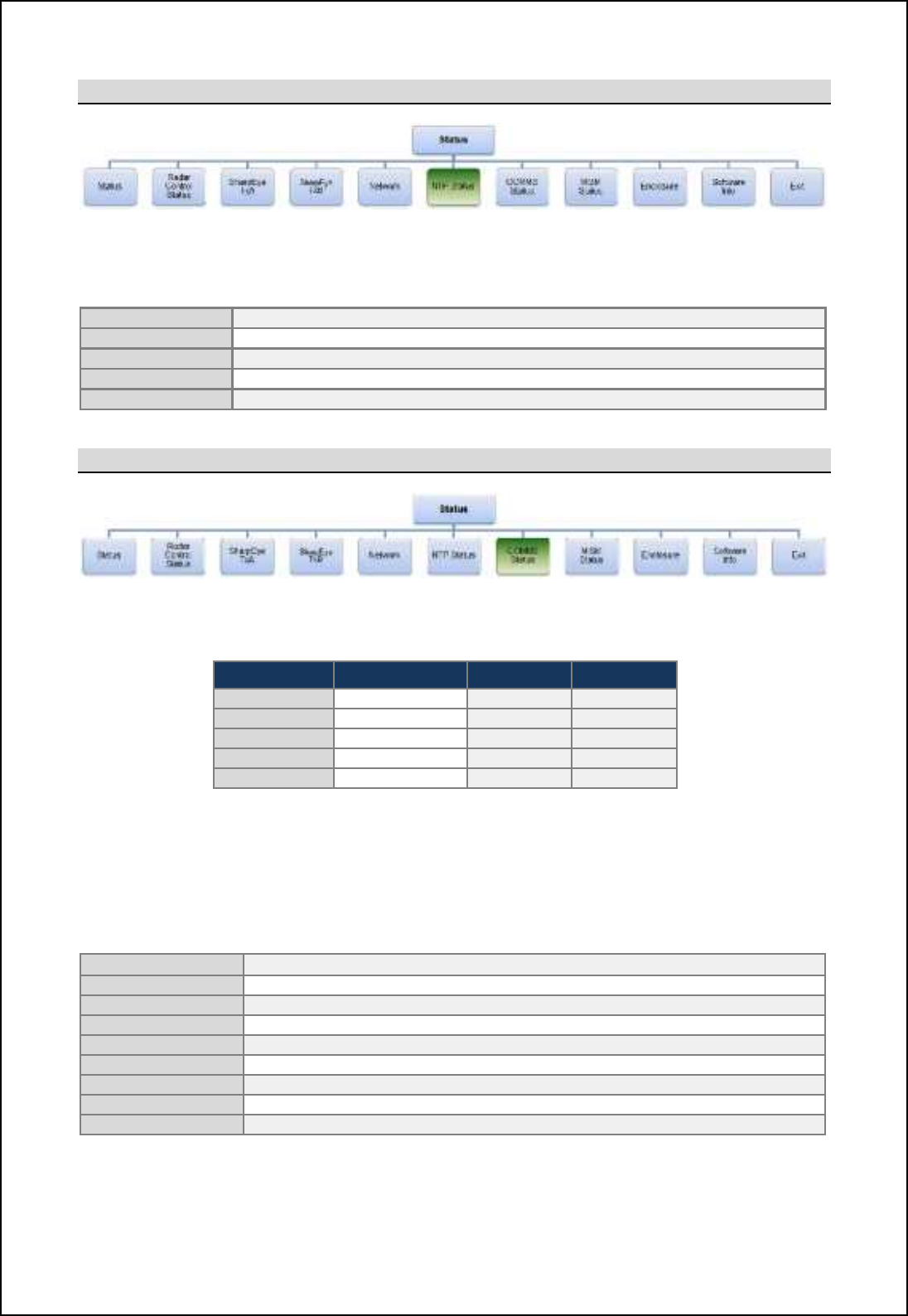
SBS-900 Shore Based Radar Systems
Chapter 6: Local operation instructions
KH-1602-2 issue 1: Standard SBS900 Systems Operator & Maintenance Handbook
Page 60 of 240
6.6.4.5 NTP Status
The IP addresses and network status can be viewed but not adjusted.
Note: In some configurations, the menu will not be present.
Time Stamp TBC
IP Address
TBC
NTP Port
TBC
Time (hh:mm:ss)
TBC
Exit
Exit the Network menu.
6.6.4.6 COMMS status
By scrolling through the COMMS status menus, the following system conditions can be viewed but
cannot be adjusted.
System Transceivers TX A Tx B
SBS
-
900
-
1
Single
X
-
band
N/A
SBS
-
900
-
2
Single
X
-
band
N/A
SBS
-
900
-
3
Dual
X
-
band
X
-
band
SBS
-
900
-
4
Dual
X
-
band
S
-
band
SBS
-
900
-
51
Single
N/A
S
-
band
In the following Active/ Inactive means:
Active: A correctly configured and connected system is switched ON and sending serial
command or status request messages.
Inactive: A correctly configured and connected system may be switched OFF or is not sending
serial messages.
SharpEye TX-A The transceiver is active or inactive
Note 1
SharpEye TX
-
B
The transceiver is active or inactive
Note 1
Comms S/E A1
TBC
Comms S/E B1
TBC
TE display
Track Extractor (TE) is active or inactive
Note 2
Service display
Service display is active or inactive
Note 2
Network Card
TBC
Enclosure
TBC
Exit
Exit the Comms status menu
Note 1: If communication between the RDU and the transceiver is lost, the RDU carries out a single power reset to the
transceiver (cycles the AC mains). If communication is not re-established the COMMS status will show Inactive.
Note 2: A request status from the track extractor or optional service display is not necessary when in the Control menu.
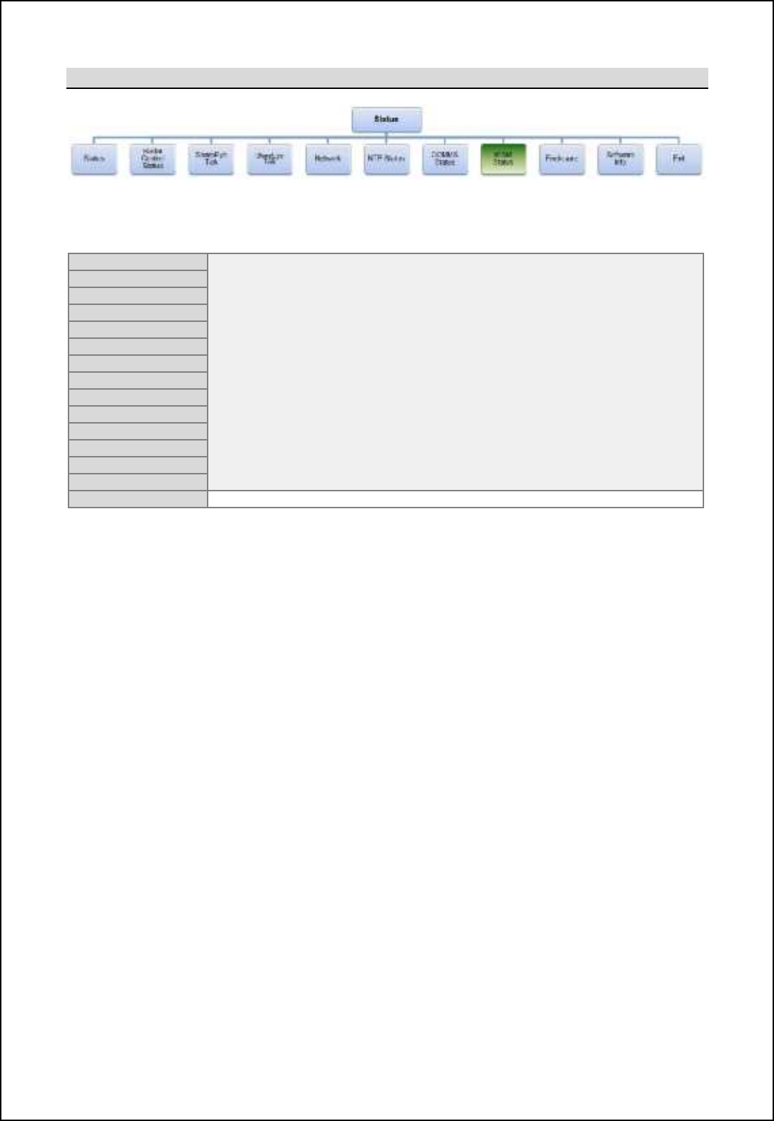
SBS-900 Shore Based Radar Systems
Chapter 6: Local operation instructions
KH-1602-2 issue 1: Standard SBS900 Systems Operator & Maintenance Handbook
Page 61 of 240
6.6.4.7 MISM status
By scrolling through the MISM status (Modular Interface System Module) menus, the status of
each of the 12 slots on the backplane can be viewed.
A1 MISB 5
Possible MISM conditions:
Empty: A PCA is not fitted in the slot.
Error: The PCA is in the wrong slot for the RDU variant.
Missing: The PCA required by the software is not present i.e.
is not loaded.
Present: The correct PCA is fitted.
Error messages: If a module is fitted in the wrong slot or is missing,
the RDU will not function further than reporting the
error.
B1 MISM 5
A2 MISM 5
B2 MISM 5
A3 I/O Mk2
B3 I/O Mk2
A4 I/O Mk2
B4 Signals
A5 Signals
B5
Comms
A6 Signals
B6 I/O Mk2
MISB
PSU
Exit
Exits the MISM status menu
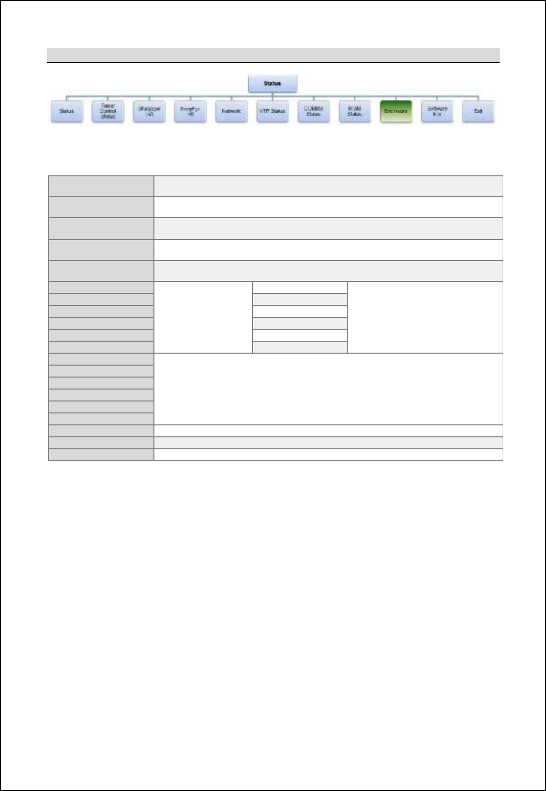
SBS-900 Shore Based Radar Systems
Chapter 6: Local operation instructions
KH-1602-2 issue 1: Standard SBS900 Systems Operator & Maintenance Handbook
Page 62 of 240
6.6.4.8 Enclosure
The status of the transceiver enclosure and optional antenna sub-assembly monitoring can be viewed
in the Enclosure menu.
Encl Temp Internal temperature of the transceiver enclosure in Degrees C.
Note: The temperature sensor is located on SBS
-
A126 PCA.
Oil level MON Status of the optional oil level monitoring
Note: Advanced antenna sub systems only.
Oil Temp MON Optional Oil Temperature status
Note: Advanced antenna sub systems only.
ENH Encoder Shows if an enhanced encoder is enabled or disabled
Note: Enabled for Advanced antenna sub systems only.
WG / FIB / POL Shows if a polarised antenna is enabled.
Note: Advanced
antenna sub systems only.
Fan A1
Optional SBS-A179
Powered Fan
assembly
Status of Fan A1
Note: In single transceiver systems. Fan
bank A or B may not be present in the
menu structure.
Fan A2
Status of Fan A2
Fan A3
Status of Fan A3
Fan B1
Status
of Fan B1
Fan B2
Status of Fan B2
Fan B3
Status of Fan B3
PSU Tx A: 3.3V
Indicates the power supply voltage.
Note: In single transceiver systems Tx A or Tx B voltages may not be present in the menu.
PSU Tx A: 15V
PSU Tx A: 13V
PSU Tx B: 3.3V
PSU Tx B: 15V
PSU Tx B: 13V
PSU INT: 15V
Indicates the power supply voltage.
PSU INT: 5.0V
Indicates the power supply voltage.
Exit
Exits the Enclosure menu
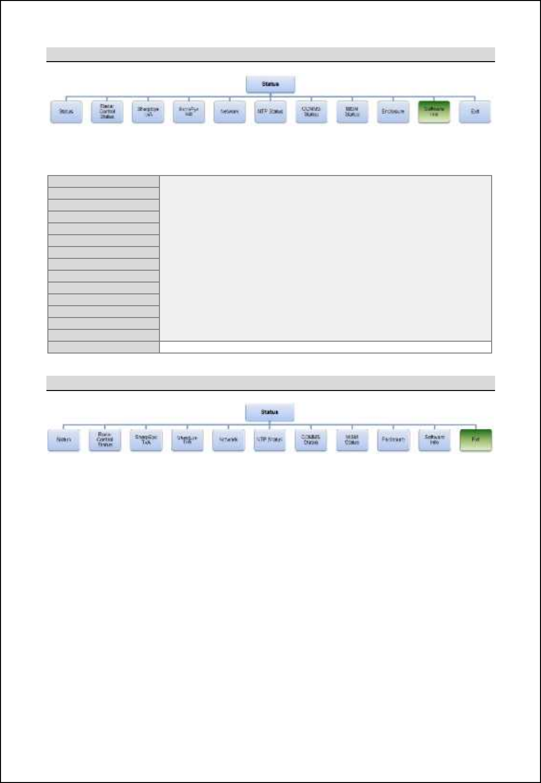
SBS-900 Shore Based Radar Systems
Chapter 6: Local operation instructions
KH-1602-2 issue 1: Standard SBS900 Systems Operator & Maintenance Handbook
Page 63 of 240
6.6.4.9 Software info
By scrolling through the software info menus, the various software versions for the system can be
identified:
MISB
Backplane
These menus display the software part and version umbers loaded into
the system.
MISB FPGA number
SharpEye
Tx A
S
/
W
SharpEye
Tx A
FPGA
SharpEye A1 Software
SharpEye A1
FPGA
SharpEye B1 Software
SharpEye B1 FPGA
SharpEye B2 Software
SharpEye B2 FPGA
SharpEye B Software
SharpEye B FPGA
Network Software
Enclosure
Exit
Exits the Software Info menu.
6.6.4.10 Exit Status menu
Selecting Exit closes the status menu and returns the display to the default menu. As no changes can
be made, there is no Save Settings function.
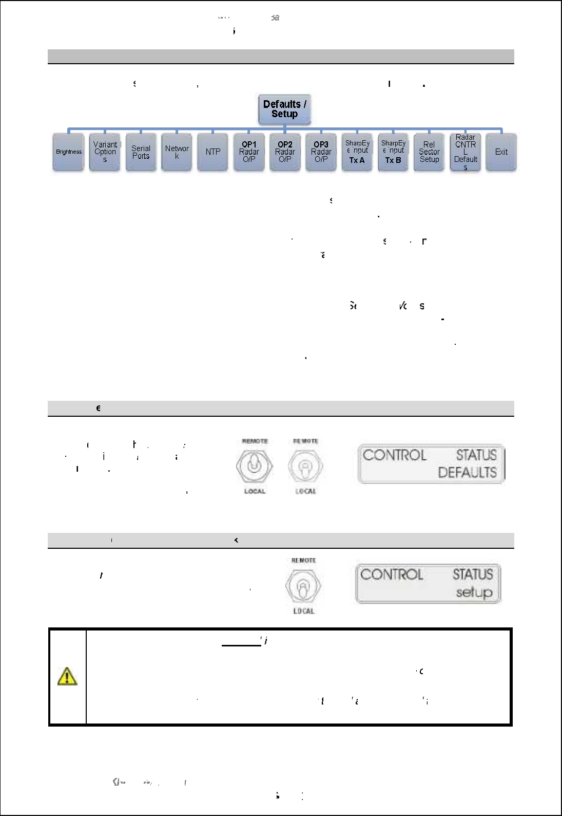
SBS
-
900 Shore
Ba
Ba
sed
Radar Systems
Chapter
6
:
Local operation instructions
KH
KH
-
1602 2
issue 1
:
Standard SBS900 Systems Operator & Maintenance Handbook
Page
64
64
of
240
6.6.5
Default and
Setup
menu
Depending on
the
system status
, the
RDU
front panel will show
Defaults
or
or
Setup
.
Default:
This is the normal operational setting and is u
sed by the operator or system
maintainer to view the system configurations
(read only)
.
Setup:
When configured for commissioning,
the Setup menu is u
sed by a
n authorised
technician or system maintainer
for
configur
ation/
setting to work.
The
Setup menu is
not used during normal operation.
Description:
The basic outline of the menu is detailed on the following pages. Detailed
explanat
ions for each setting can be found in the
S
etting to
W
ork
section of the
system Installation and Commissioning handbook (reference KH
-
1602
1).
Menu variations:
The menu structure can vary depending on the system variant selected. For
example in a single X
band system, the
SharpEye IP Tx B
and
Fan Band B
menus
are not present.
Default m
enu
(normal use)
When the service display is
inactive
(off
-
line)
, t
he
Default
menu
is available
in both
Remote
and
Local
modes
Settings in the
D
efault menus
can
be viewed but
cannot
be adjusted.
or
Setup menu
(Commissioning/ setting to work
)
The
Setup
menu
is only available when the
service display is offline, the
switch is set to
Local
and
the RDU is configured to be commissioned.
Caution:
The Setup menu is
not used
in normal operation as it allows the commissioning
and setting to work of the SBS system.
Incorrect configuration in the setup menus can the system
performance
or inhibit
operation.
The setup menus
must
only be used by a suitably
trained
and authorised
technician or
system
maintainer.

SBS-900 Shore Based Radar Systems
Chapter 6: Local operation instructions
KH-1602-2 issue 1: Standard SBS900 Systems Operator & Maintenance Handbook
Page 65 of 240
6.6.5.1 Brightness
Brightness is used to set the backlight brilliance of the LCD front panel on the Radar Distribution Unit.
Bright
+
Increases the backlight brilliance of the front panel.
Bright -Decreases the backlight brilliance of the front panel.
6.6.5.2 Variant Options
The Variant Options menu shows the system configuration.
SBS variant Shows the SBS system number
i.e.
SBS
-
900
-
1
.
CAN Mode Shows the CAN mode as OFF, RIU, TIU or Fixed.
CAN Address
To Be Confirmed
.
TX PSU CONT Set to Always ON in SBS-900 systems.
Days to Swap Shows the number of days until the transceiver automatically swaps (Dual transceiver
systems only).
Door switch Enabled where a Hut door security switch is connected.
WG dryer
Enable
d when the optional
pressurized waveguide dryer is
i
nstalled.
Platform switch Enabled where an Antenna Platform security switch is fitted.
Horizontal POL
Enabled when a polarised antenna is being fitted.
Circular POL
Anti-clock POL
Vertical POL
ENH Encoder Fitted is displayed when an enhanced encoder is installed.
Oil status Enabled when the optional oil monitoring input from the Advanced antenna Turning Unit is
installed.
Fan Bank A Enable or disable the optional powered fan kit for Tx A.
Note: In single Transceiver systems, this menu may not be present.
Fan Bank B Enable or disable the optional powered fan kit for Tx B.
Note: In
single Transceiver systems, this menu may not be present.
Active Fan Set the temperature that Fan Bank A switches on or set to permanently ON.
Note: In single Transceiver systems, this menu may not be present.
Reserve Fan Set the temperature that Fan Bank B switches on or set to permanently ON.
Note: In single Transceiver systems, this menu may not be present.
Minimum FREQ Displays nb_ gchcgog [p[cf[\f_ Rb[ljDs_x `l_ko_h]s.
Maximum FREQ
Displays
nb_ g[rcgog [p[cf[\f_ Rb[ljDs_x `l_ko_h]s
.
Low RPM Enabled when LOW RPM antenna speeds have been commissioned.
High RPM
Enabled when HIGH RPM antenna speeds have been commissioned.
Auto RPM Enabled when AUTO RPM antenna speeds have been commissioned.
Alt Chan Plan This allows the system to
Note: System
specific menu, this may not be present in standard system.
Ant Gain Allows the selection of the antenna gain when Alt Chan Plan is selected.
Note: System specific menu, this may not be present in standard system.
EXIT
Exits the Variant Options Menu
.
6.6.5.3 Serial Ports
The serial ports menu displays the baud rates configured for the serial outputs to the transceiver,
Service Display (SKL: Service display serial port) or the optional analogue track extractor (SKK: TE
serial port).
TE port Displays the Baud Rate for the Track Extractor (TE) output
Service port
Displays the Baud Rate for the Service Display.
TX/ RX A Ccmjf[sm nb_ A[o^ Q[n_ `il nb_ Rb[ljDs_x SW . Qr @-
TX/ TX B
Ccmjf[sm nb_ A[o^ Q[n_ `il nb_ Rb[ljDs_x SW . Qr A-
EXIT
Exits the Serial Ports menu
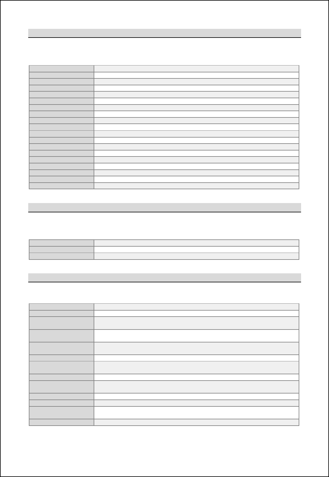
SBS-900 Shore Based Radar Systems
Chapter 6: Local operation instructions
KH-1602-2 issue 1: Standard SBS900 Systems Operator & Maintenance Handbook
Page 66 of 240
6.6.5.4 Network
The Network menu shows the system settings for the network.
Note: In ASTERIX enabled systems, this menu may not be present.
Range limit 48nm is the factory default
Video
timing
Frame is the factory default
Video reports Continuous is the factory default
Local SAC SIC ID
To Be Confirmed.
Destination SAC SIC ID System area code and security identifier
IP ADDR Default IP address for the Radar Distribution Unit
Gateway
ADDR
Default gateway address for the Radar Distribution Unit
Network ADDR Default Netmask address for the Radar Distribution Unit
Multicast ADDR
Default multicast address for the Radar Distribution Unit
Time to Live To Be Confirmed.
MTU 1500 is the factory default
Fragment
IP is the factory default
Source port To Be Confirmed.
Dest port
To Be Confirmed.
Video Gain To Be Confirmed.
Video Offset To Be Confirmed.
Pre
-
Sync Time
To Be Confirmed.
Bihnlif Uc[} To Be Confirmed.
Exit
Exits the Network
menu
6.6.5.5 NTP time
Display of the NTP (Network Time Protocol) time settings.
Note: In ASTERIX enabled systems, this menu may not be present.
Time stamp Displays if NTP time is ON or OFF
NTP IP ADDR
Shows the default IP
address (192.168.022.071)
NTP port Shows the default port (00123)
6.6.5.6 OP1, 2 & 3 Radar O/P
This menu displays the RDU analogue levels for outputs 1, 2 and 3.
HL O/P widths Displays the heading line output pulse width
AZ
O/P width
Displays the azimuth output pulse width
AZ/HL STAB Displays if the azimuth is stabilised or unstabilised.
This is set to UNSTAB for all SBS-900 systems
AZ/HL type Displays if the Heading line is Quadrature or Pulsed.
This is set to Pulse for all SBS-900 systems
AZ/HL ratio Displays the Azimuth / Heading Line ration.
This is set to 4096:1 for all SBS-900 systems
AZ/HL DIRECTN
Set to Normal for all SBS
-
900 systems
AZ/HL O/P
Displays a value between 0 and 63 that is used to set the azimuth and heading line
output voltage. Note
Video gain Displays a value between 0 and 63 that is used to set the video output gain.
Note
Video offset Displays a value between 0 and 63 that is used to set the video output offset with
respect to ground/ 0V.Note
PRESYNC time Displays the pre-sync (Sync Delay) time used for range alignment.
Sync output
Displays a value between 0 and 63 that is used to set the Sync output.
Note
Blanking O/P Displays a value between 0 and 63 that is used to set the blanking output
amplitude Note
EXIT
Exits the OP1, 2 or 3 Radar O/P menu
Note: This is NOT an indication of the actual voltage output level.
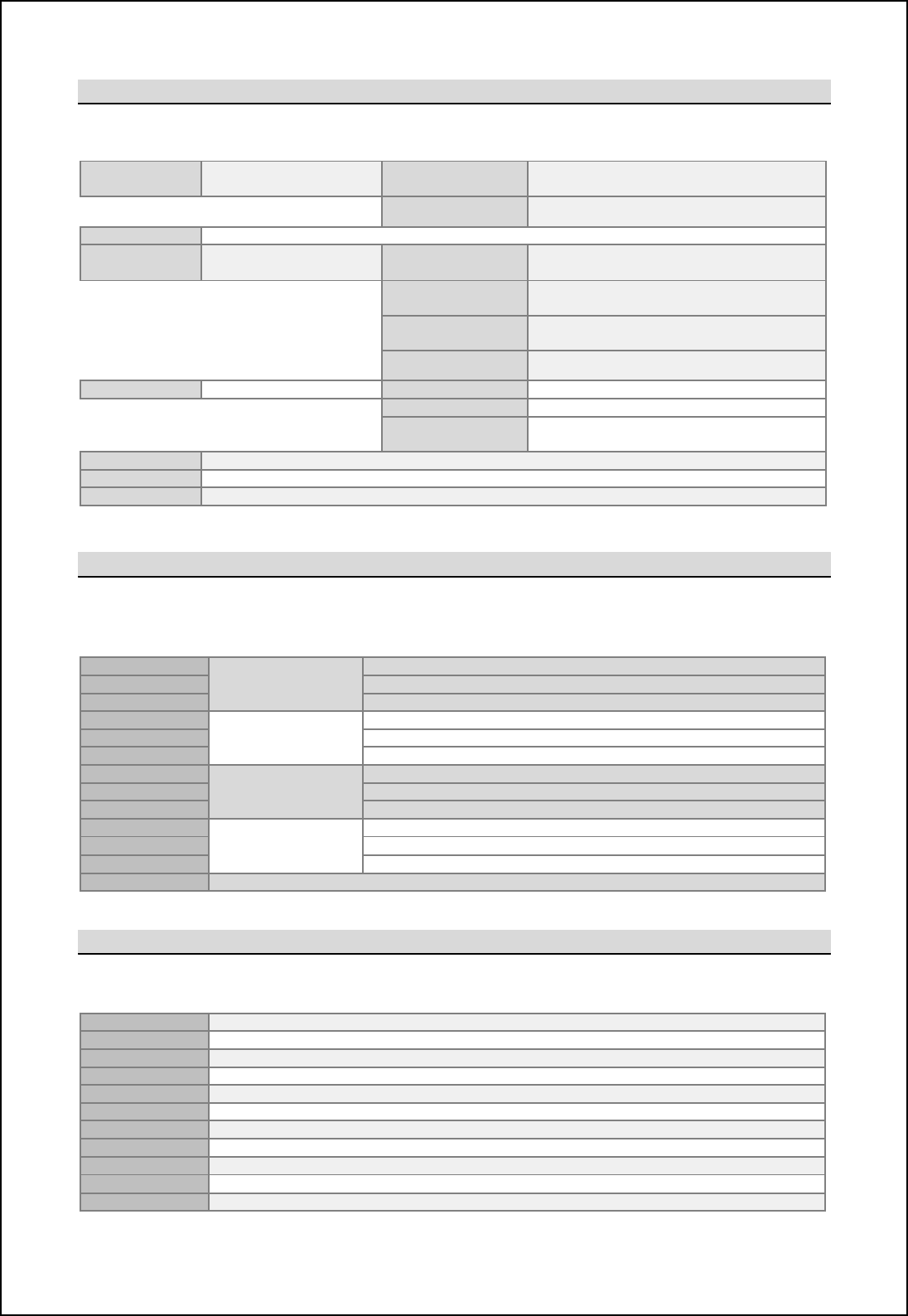
SBS-900 Shore Based Radar Systems
Chapter 6: Local operation instructions
KH-1602-2 issue 1: Standard SBS900 Systems Operator & Maintenance Handbook
Page 67 of 240
6.6.5.7 SharpEye IP Tx A & B
Note: The Tx A or Tx B menu may not be present in single transceiver systems.
6.6.5.8 Rel Sector
The following menu displays the start and stop bearings of each of the four relative blanking sectors.
It also shows if the sectors are enabled or disabled.
R SEC START 1 Relative Sector 1 Displays the start bearing of mute
R SEC END 1 Displays the end bearing of mute
R SEC ENA 1
Shows if the Mute Sector is Enabled or Disabled
R SEC START 2 Relative Sector 2 Displays the start bearing of mute
R SEC END 2
Displays the end bearing of mute
R SEC ENA 2
Shows if the Mute Sector is Enabled or Disabled
R SEC START 3 Relative Sector 3 Displays the start bearing of mute
R SEC END 3
Displays the end bearing of mute
R SEC ENA 3 Shows if the Mute Sector is Enabled or Disabled
R SEC START 4
Relative Sector 4
Displays the start bearing of mute
R SEC END 4
Displays the end bearing of mute
R SEC ENA 4 Shows if the Mute Sector is Enabled or Disabled
EXIT
Exits the Rel Sector menu
6.6.5.9 Radar CNTRL (Control) Defaults
This menu displays the Radar Control Defaults settings.
Radar Source
Shows which t
ransceiver
is selected in
dual systems
Range mode Current instrumented range of 24nm or 48nm.
TX power Rb[ljDs_x ionjon jiq_l i` Kiq il bcab-
TX frequency
Shows which of the
SharpEye
TM
transmission frequencies is selected.
Mute Indicates if the Mute is switched ON or OFF.
SEA
Shows the configured value of the Sea filter (000
min.
to 255
max.
).
RAIN Shows the configured value of the Rain filter (000
min.
to 255
max.
).
Int
rejection
Shows if interference rejection is set to OFF or Lower.
Sweep
Shows if the sweep is set to Forward (default) or reverse.
RPM Shows the selected speed (revolutions per minute) of the antenna motor.
Exit
Exits the Radar control status menu.
FREQ/ HL
Skew
New sub menu +HL SKEW Displays the Heading Line skew for each
SharpEye
frequency
that
is
enabled
.
Exit ,Returns to the SharpEye IP menu.
FD Squint
To Be Confirmed
Blanking O/P New sub menu +Blanking Pre Displays the value of the pre blanking
pulse.
Blanking Post Displays the value of the post blanking
pulse.
Blanking
Threshold TBC
Exit ,Returns to the SharpEye IP menu.
Serial control
New sub menu
+
External COM 3
:
TBC
External COM 4: TBC
Exit ,Returns to the SharpEye IP menu.
Video source Indicates which MISM PCA is the source the Video
AZ HL source
Indicates which MISM PCA is the source the ACP/ ARP
EXIT Exits the SharpEye IP Tx A or Tx B menu

SBS-900 Shore Based Radar Systems
Chapter 6: Local operation instructions
KH-1602-2 issue 1: Standard SBS900 Systems Operator & Maintenance Handbook
Page 68 of 240
Page intentionally blank

SBS-900 Shore Based Radar Systems
Chapter 7: Remote operation instructions
KH-1602-2 issue 1: Standard SBS900 Systems Operator & Maintenance Handbook
Page 69 of 240
7 Remote operation instructions
When the Radar Distribution Unit is set to Remote operation, the external
command and display system or track extractor has control of the system.
For test purposes, the optional service display can be configured for Remote
control and be connected to the track extractor (TE) port to test the serial port
functionality.
RDU Local control: With the switch set to Remote, Local control of the system via the Radar
Distribution Unit is NOT possible.
7.1 Remote control operator instructions
External command and display and track extractor
Operator instructions for the external command and display or track extractor systems are not
included in this handbook; please refer to the suppliers system handbooks for instructions.
Service display (optional)
The operator instructions for the service display and service display control software can be found in
Annex A of this handbook.
7.2 External commands
The commands sent and received by the SBS-900 system are detailed in a separate document
reference KSD-4750: Serial Control of SBS Radar Systems which is available upon request.
Alternatively a copy can be found in Annex B of the system installation manual KH-1602-1.

SBS-900 Shore Based Radar Systems
Chapter 7: Remote operation instructions
KH-1602-2 issue 1: Standard SBS900 Systems Operator & Maintenance Handbook
Page 70 of 240
7.3 Remote control operational states
Eil nb_ joljim_m i` nb_ `iffiqcha _rjf[h[ncihm+ nl[]e _rnl[]nil g_[hm nb_ om_lm ]igg[h^ [h^
display system or track extractor.
System
OFF
System
configuration
'Single and three-phase AC supplies to the RDU are available.
'The AC Breakers within RDU are OFF.
'Antenna Rotation keyswitch & Man aloft switch both set to OFF.
'Remote/ Local &Standby/ RUN switches on the RDU are set to Remote &
Standby.
'Commands being received from the Service Display.
System status
'AC power is present within the RDU but as the breakers are in the OFF
position, the dual redundant power supply is OFF and no DC rails are
being generated.
The Radar Distribution Unit is OFF.
'Single and three-phase mains voltages are NOT sent to the transceiver /
gearbox.
System
RUN
Safety
switches
OFF
System
configuration
'Single and three-phase AC supplies to the RDU are switched ON.
'The AC Breakers within RDU are ON.
'Antenna Rotation keyswitch OR Man Aloft switch set to OFF.
'Remote/ Local &Standby/ RUN switches on the RDU are set to Remote &
Standby.
System status
'The RDU detects that the Antenna Rotation keyswitch OR Man Aloft
switches are in the OFF position. This breaks the safety switch current loop.
'The single and three-phase relays are opened and AC power to the
transceiver/ gearbox is switched OFF.
'Antenna rotation and transmission is not possible.
'The Service Display has no control over the system.
System
Standby
System
configuration
'Single and three-phase AC supplies to the RDU are available.
'The AC Breakers within RDU are ON.
'Antenna Rotation keyswitch & Man Aloft switch are both set to FREE.
'Remote/ Local &Standby/ RUN switches on the RDU are set to Remote &
Standby.
'No commands being received from the Service Display.
System status
'The RDU is switched ON. The software reads the condition of the Antenna
Rotation keyswitch and Man Aloft switch, detects these are in the FREE
position so makes relays within the breakers sending AC power to the
transceiver and gearbox.
'The antenna commences rotation regardless of the RUN command
State. Note
'The SharpEye transceiver switches ON and after a 30 to 40 second warm-
up time enters a standby state waiting for a RUN command from the RDU.
'System and BITE data from both the RDU and transceiver is available.
'The system is now in standby waiting for system commands.
Remote
control
System
RUN
System
configuration
'Single and three-phase AC supplies to the RDU are available.
'The AC Breakers within RDU are ON.
'Antenna Rotation keyswitch & Man Aloft switch both set to FREE.
'Remote/ Local &Standby/ RUN switches on the RDU set to Remote &
Standby.
'
A
RUN command
is being received
.
System status
'The RDU detects the RUN command which is sent to the transceiver.
'The SharpEye is in a standby state with the antenna running. When the run
command is received from the RDU the system commences transmitting.
'Radar signals, ACP, ARP and heading line data is sent to the radar I/O
module within the Radar Distribution Unit.
'The RDU processes the transceiver data and sends it to the track extractor
and optional service display.
Note: Antenna rotation can be over-ridden in the Control Defaults menu.

SBS-900 Shore Based Radar Systems
Chapter 7: Remote operation instructions
KH-1602-2 issue 1: Standard SBS900 Systems Operator & Maintenance Handbook
Page 71 of 240
Transceiver operating states
The following table shows the various operation states of the SharpEyeTM transceiver.
The antenna will rotate regardless of the transceiver state.
Operation state Description
OFF Power is not applied to the transceiver which is switched OFF.
Initialise
On completion of initialisation the transceiver switches to standby or, if any of
the self-test checks fail, to fault state.
The system initialisation typically takes 30 to 40 seconds after which time the
system becomes available for operation.
Standby
In standby the transceiver establishes communication with the Radar
Distribution Unit and reports its status.
The transceiver receives and acts on commands from the RDU.
In Standby the antenna rotates but the system does not transmit.
Transmit
When a RUN command is received from the Radar Distribution Unit and
ACP/ARP signals are present, the SharpEyeTM transmits.
The transceiver initially outputs at low power. The radar returns are then
processed enabling the VSWR to be checked without the risk of damage to the
transceiver.
If the VSWR is within limits then the transceiver automatically switches to full
power.
If the VSWR is high, indicating an antenna fault, a warning message is sent to
the Radar Distribution Unit and the transceiver enters the degraded Low
Power state.
Degraded
(Low power)
The transceiver continuously runs background performance checks on forward
power, reverse power, receiver sensitivity and temperature. If any of these
parameters falls outside predetermined levels a warning message is sent to
the Radar Distribution Unit indicating the nature of the fault.
The transceiver continues to operate, but with reduced performance and
functionality.
Fault
If the performance or functionality is degraded such that the transceiver cannot
operate it enters the fault state and a fault message is sent to the display
equipment.
The transceiver stops radiating RF and there is no video output to the Radar
Distribution Unit.
A spurious fault may be cleared by re-powering the equipment.
Communication
error
If communication is lost between the Radar Distribution Unit and the
SharpEyeTM, the RDU reboots the SharpEyexleading to a potential 20
second gap in coverage.

SBS-900 Shore Based Radar Systems
Chapter 7: Remote operation instructions
KH-1602-2 issue 1: Standard SBS900 Systems Operator & Maintenance Handbook
Page 72 of 240
Page intentionally blank
SBS-900 Shore Based Radar Systems
Chapter 8: Service display/ RadarView control
KH-1602-2 issue 1: Standard SBS900 Systems Operator & Maintenance Handbook
Page 73 of 240
8 Service display/ RadarView control
8.1 Overview
SBS systems can be controlled and radar returns viewed using the optional range of service displays.
Service displays can be used as a maintenance/ commissioning tool or when correctly configured, as
a primary means of system control.
There are a number of service display options for the SBS series as follows:
Service display part number & description SBS-900-1
SBS-900-2
SBS-900-51
SBS-900-3
SBS-900-4
SBS-A3-2 Single radar sensor
Base components for integration into a 3rd party supplied PC & &
SBS-A3-3 Single radar sensor display
RS232/ ASTERIX control & monitoring & &
SBS-A3-5 Single radar sensor
LAN/ ASTERIX and RS232 control & monitoring
(No radar input card fitted)
%&
LAN kit required.
See Note
All service displays are supplied with the following software pre-loaded.
ZM-2283
RadarView software
RadarView Software: This software provides the radar processing and display
and has integrated control and monitoring functions for the SBS series.
Operator instructions: The use and operator instructions for the ZM-2283
RadarView and SBS control software can be found in Annex B.
8.2 SBS-A3-2 Base system
The SBS-A3-2 allows the serial control of a single transceiver system via a customer supplied third
party PC/ Microprocessor. See the options section in the system overview handbook for the minimum
PC specification.
The kit provides all the hardware and software to be installed onto a PC to make the system
compatible with the SBS series and comprises the following:
Kelvin Hughes
part number Description
SBS-A109 08 l[]e giohn[\f_ '0T( mervice display patch panel and cables
ZM-2283 RadarView software including SBS radar control and replay software for
maintenance displays.
Supports of HPx-200 and/ or Asterix video.
45-980-0041-001 HPx-200 PCI radar interface card
ZM-2602 SBS service display graphic V2
Note: The SBS-A3-5 service display can only be used with the LAN kit is fitted.
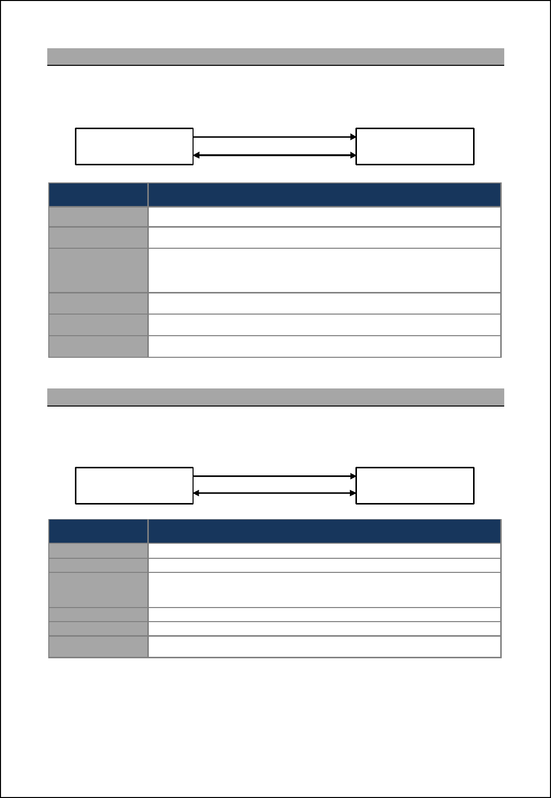
SBS-900 Shore Based Radar Systems
Chapter 8: Service display/ RadarView control
KH-1602-2 issue 1: Standard SBS900 Systems Operator & Maintenance Handbook
Page 74 of 240
8.3 SBS-A3-3 Single transceiver
The SBS-A3-2 ecn ]ihn[chm [ 08 l[]e giohn[\f_ '1T( gc]lijli]_mmil jl_fi[^_^ qcnb [ff nb_
necessary software and an interface place for connecting the system to a single transceiver system.
Kelvin Hughes part
number
Description
45-975-0183-001 08 '2U) rack mountable microprocessor.
SBS-A109 08 l[]e giohn[\f_ '0T( mervice display patch panel and cables
ZM-2283 RadarView software including SBS radar control and replay software for
maintenance displays.
Supports of HPx-200 and/ or Asterix video.
45-980-0041-001 HPx-200 PCI radar interface card (preinstalled into the PC)
ZM-2602 SBS service display graphics card (preinstalled into the PC)
SBS-A124-11 Cable kit for connecting the SBS-A109 plate to the SBS system (11m)
Note: Other cable lengths are available; please contact Kelvin Hughes for additional details.
8.4 SBS-A3-4 dual transceiver
The SBS-A3-3 ecn ]ihn[chm [ 08 l[]e giohn[\f_ '1T( gc]lijli]_mmil jl_fi[^_^ qcnb [ff nb_
necessary software and two interface places for connecting to a dual transceiver system.
Kelvin Hughes part
number
Description
45-975-0183-001 08 '2U) rack mountable microprocessor.
SBS-A109 1 r 08 l[]e mountable (1U) service display patch panel and cables
ZM-2283 RadarView software including SBS radar control and replay software for
maintenance displays.
Supports of HPx
-
200 and/ or Asterix video.
45-980-0041-001 2 x HPx-200 PCI radar interface card (preinstalled into the PC)
ZM-2602 SBS service display graphics card (preinstalled into the PC)
SBS-A124-11 Cable kit for connecting the SBS-A109 plate to the SBS system (11m)
Note:
Other
cable
lengths are available; please contact Kelvin Hughes for
additional details.
SBS-A3-3
Service display
Single transceiver
SBS system Video/ Sync (analogue)
Serial control
SBS-A3-3
Service display
Dual transceiver
SBS system 2 x Video/ Sync (analogue)
2 x Serial control
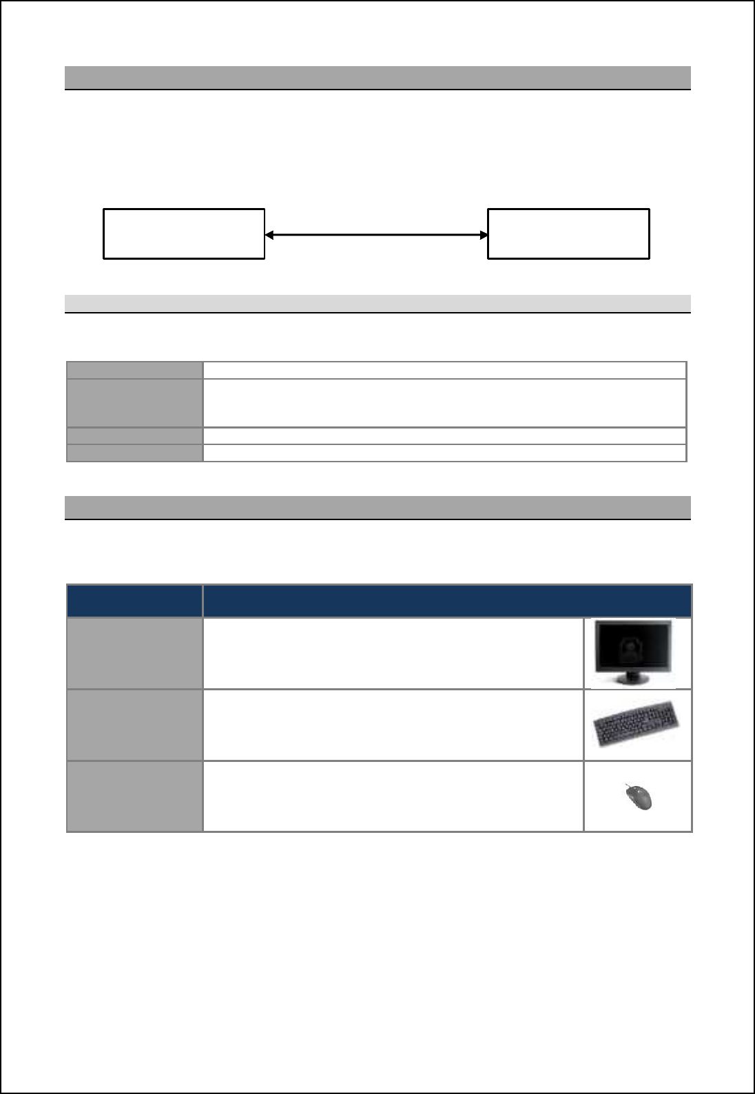
SBS-900 Shore Based Radar Systems
Chapter 8: Service display/ RadarView control
KH-1602-2 issue 1: Standard SBS900 Systems Operator & Maintenance Handbook
Page 75 of 240
8.5 SBS-A3-5 ASTERIX control
The SBS-A3-4 ecn ]ihn[chm [ 08 l[]e giohn[\f_ '1T( gc]lijli]_mmil jl_fi[^_^ qcnb [ff nb_
necessary software for connection to a dual transceiver system.
The service display can accept ASTERIX video and control is possible via Serial or LAN connection.
Note
Kit contents
The SBS-A3-4 dual radar service kit comprises of the following:
45-975-0183-001 08 '2U) rack mountable microprocessor.
ZM-2283 RadarView software including SBS radar control and replay software for
maintenance displays.
Supports of HPx
-
200 and/ or Asterix video.
ZM-2602 SBS service display graphics card (preinstalled into the PC)
SBS-A220-11 Cable kit for connecting the SBS-A109 plate to the SBS system (11m)
Note
2
8.6 Keyboard, monitor & Mouse
The processor requires a flat screen display, standard USB QWERTY keyboard and USB mouse (not
supplied). If these are required the following commercial off the shelf products can be supplied:
Kelvin Hughes part
number Description
Monitor
45-975-0189-001
22 inch wide screen LCD monitor.
Auto-ranging AC input 110VAC to 230VAC 47Hz to 63Hz.
Case colour black.
Keyboard
45-975-0191-001 USB QWERTY keyboard, case/ key colour black.
Mouse
45-975-0190-001 Black USB optical scroll mouse with three buttons.
Note 1: LAN control is only available when the LAN interface kit has been fitted to the Radar Distribution Unit (kit reference
SBS-A129).
Note 2: Other cable lengths are available; please contact Kelvin Hughes for additional details.
SBS-A3-3
Service display
Dual transceiver
SBS system 2 x Serial control
Or LAN control
Note 1
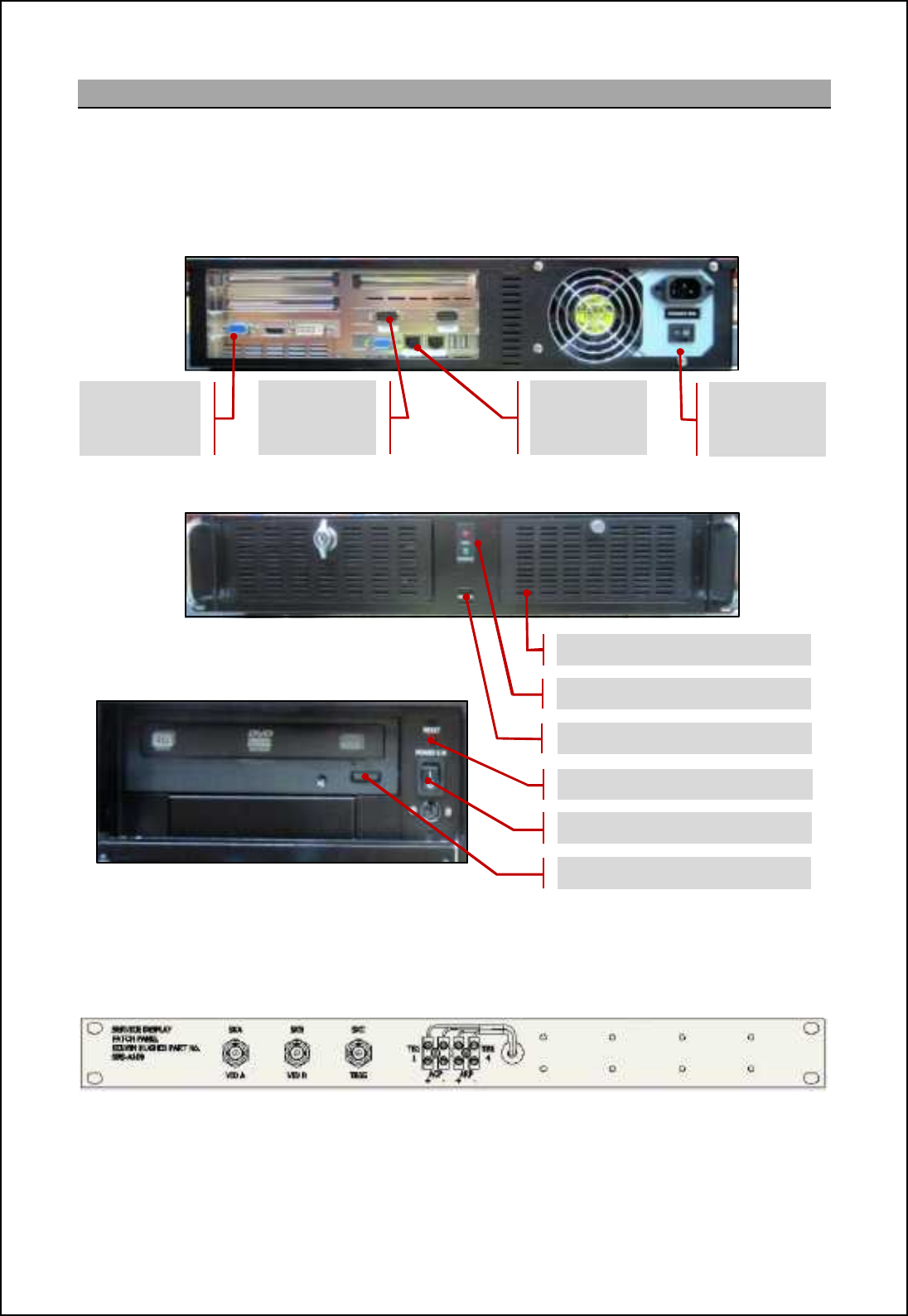
SBS-900 Shore Based Radar Systems
Chapter 8: Service display/ RadarView control
KH-1602-2 issue 1: Standard SBS900 Systems Operator & Maintenance Handbook
Page 76 of 240
8.7 Service Display PC overview
Sb_ `iffiqcha acp_m [h ip_lpc_q i` nb_ 08 '1T( l[]e giohn_^ gc]lijli]_mmil om_^ ch nb_
SBS-A3-3,-4 &-5 service displays.
Note: The make and model of the service display PC may change from the version shown however the switch functionality
and input/ output connectivity will be similar.
SBS-A3-3 Service display front view
Detail of service display controls
SBS-9.-67 .6q eTV^ `bhagTU_X %.M& fXei\VX W\fc_Tl \agXeYTVX c_TgX7
The following plate is used to connect signals to the service display (1 plate required per transceiver).
The system runs the software required to display and control a single radar sensor but does not
include a monitor, keyboard or mouse.
Air filter
Reset switch
Power switch
DVD open/ close button
2 x USB port
Power & Hard drive LED
Mains input
and Power
switch
LAN input
COM 1
(Serial
connection)
VGA / HDMI /
AVI outputs

SBS-900 Shore Based Radar Systems
Chapter 8: Service display/ RadarView control
KH-1602-2 issue 1: Standard SBS900 Systems Operator & Maintenance Handbook
Page 77 of 240
8.8 Switching ON/ OFF
SBS-A3-2: Third party system
The operation of third party PC equipment used in the SBS-A3-2 service display is not detailed within
this handbook. Please refer to the user manuals supplied with the original third party equipment.
SBS-A3-X: 2U 19 inch processor rack
The following details the switching ON/ OFF of the microprocessor used in the SBS-A3-3,-4
&-5.
Switch ON
i. Ensure an AC mains supply is connected to the system and is switched
ON (115/ 230VAC auto-ranging)
ii. Open the front panel of the service display processor.
iii. Place the power switch into the ON ( I ) position.
iv. The green power LED illuminates and the processor will start.
Run RadarView
application
When the service display has started, run the RadarView
application from the desktop.
A brief overview of the operation of RadarView software
can be found in the following section. RadarView desktop icon
Reset
If a system lockup or freeze occurs, temporarily press the Reset switch which
restarts the processor.
Caution: Pressing reset aborts all programs that are running. All unsaved work and
temporary configurations will be lost. The main system configurations and settings are
retained.
Closing the
RadarView
application
Prior to switching the OFF service display, the RadarView application must be
closed.
Shut-down and
switch OFF
Ensuring the RadarView application has closed, shut down the system using
the Start/shutdown function from the Windows desktop.
When Windows has shut-down, place the power switch into the OFF (0)
position or if the switch is spring loaded, press and hold the OFF button for 5
seconds)
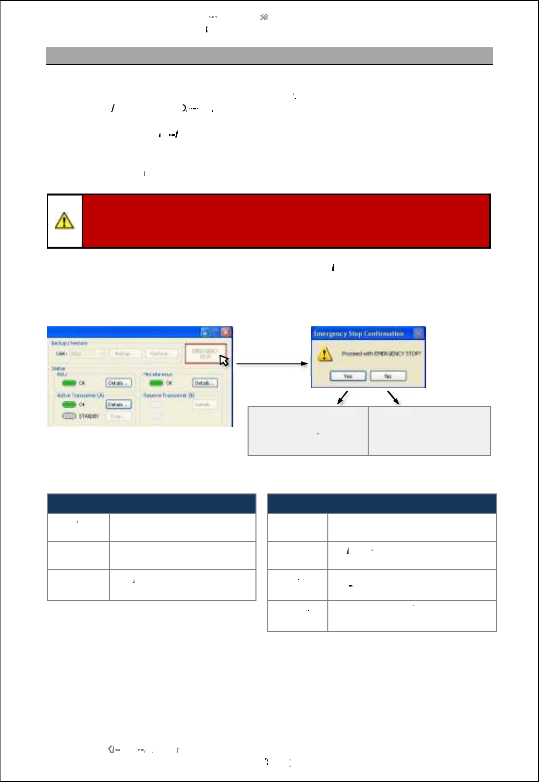
SBS
-
900 Shore
Ba
Ba
sed
Radar Systems
Chapter
8
:
Service display/ RadarView control
KH
KH
-
1602 2
issue 1
:
Standard SBS900 Systems Operator & Maintenance Handbook
Page
78
78
of
240
8.9
Emergency Stop
The Emergency Stop is a function within the RadarView software that isolates power to the
transceiver
enclosure
and antenna turning
sub assembly
. This function is only available when the
service display
/ RadarView
is
ON
ON
-
line
If the Service display is
off
line
the Emergency Stop
function
cannot be accessed/ used.
Emergency Stop is designed to be used by the operator if an emergency situation is detected that
requires immediate sh
utdown of the transmission system.
Caution:
The software Emergency Stop function must never be used to stop the system for
maintenance purposes or for working aloft.
The system must be fully isolated from all sources of power prior to carrying out any maintenance
task or before working aloft.
To activate the Emergency Stop function, select
Channel A
then
% 1=175) 14 1AJ
from the
RadarView main screen.
Press the
Emergency stop button and the following occurs:
Yes
Antenna rotation and
system transmission is
stopped.
NO
NO
Action cancelled.
The system continues to
operate normally.
When the Emergency Stop is activated, the following system changes occur:
RadarView software
Radar Distribution Unit
Antenna
Speed:
Stop
is automatically selected.
AC power:
Single & three phase relays (R1, R2
and CON1) switch OFF.
Transceiver
Mode:
Standby
is automatically selected.
Alarm:
An
Emergency Stop
alarm is
generated
at the RDU.
Stop
button:
The
Emergency Stop
button text
changes to
Restart.
Antenna
rotation
AC power is removed
from the Antenna
Sub
System.
Antenna rotation is stopped.
Transceiver
Enclosure
AC power is removed from the
transceiver
Enclosure.
System transmission is stopped.
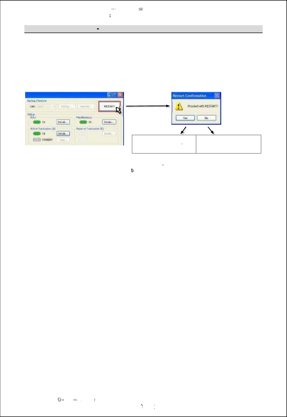
SBS
-
900 Shore
Ba
Ba
sed
Radar Systems
Chapter
8
:
Service display/ RadarView control
KH
KH
-
1602 2
issue 1
:
Standard SBS900 Systems Operator & Maintenance Handbook
Page
79
79
of
240
Emergency Stop
p
system re
-
start
When the situation that caused the Emergency Stop function to be activated has been cleared, the
system must be restarted:
Pressing the
Restart
button is pressed configures the RDU so that it is ready to go to RUN.
Further operator action is required from the RadarView software to then commence system
transmission and antenna rotation:
Yes
The RDU is available to
restart transmission
NO
NO
Action cancelled.
Antenna Speed:
Select the
required antenna speed
Transceiver Mode:
Switch from
Standby
to
RUN
to commence transmission.
The system will now operate normally.
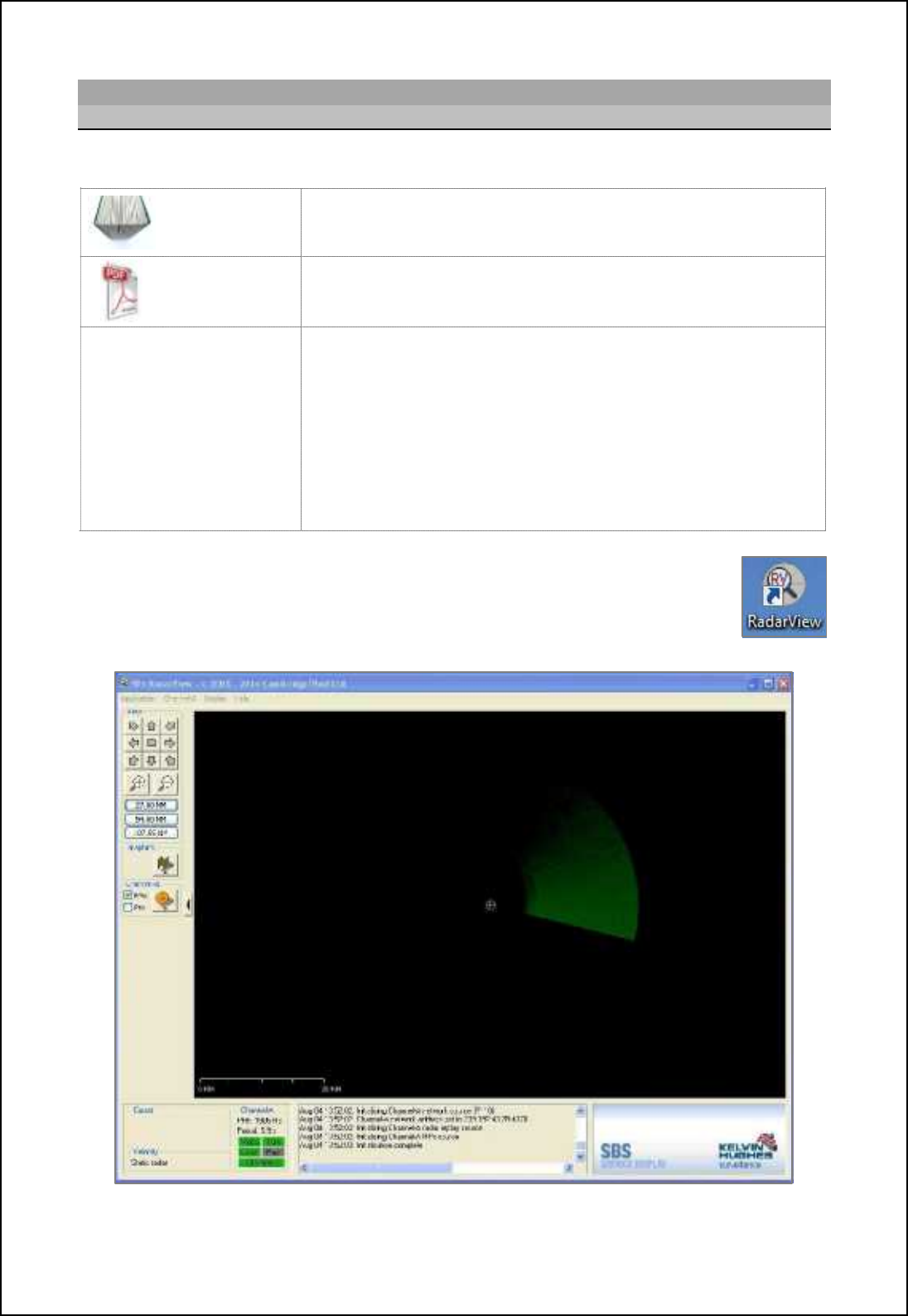
SBS-900 Shore Based Radar Systems
Chapter 8: Service display/ RadarView control
KH-1602-2 issue 1: Standard SBS900 Systems Operator & Maintenance Handbook
Page 80 of 240
8.10 RadarView operator overview
8.10.1Overview
The manufactures operator handbook for RadarView can be located as follows:
Printed copies In printed copies of this handbook, a copy of the RadarView user
manual can be found in section Annex B.
Electronic
copies (PDF) In electronic copies, the RadarView user manual can be found in the
root directory of the KH1600 document (PDF format).
Document details and
copyright notice:
Cambridge Pixel
RadarView
user manual
SPx RadarView for Windows User Manual
Document number: CP-25-110-27
Kelvin Hughes Ltd is not responsible for the content of the
RadarView user manual which remains the copyright of Cambridge
Pixel Ltd.
Document reference CP-25-110-27 contains proprietary information that is
sensitive to the commercial interests of Cambridge Pixel Ltd. The contents
of this document should not be communicated to third parties without the
prior written consent of the Company.
The following i``_lm [ \lc_` ip_lpc_q i` nb_ Q[^[lUc_q ij_l[nilm m]l__h. Users must
refer to the manufactures handbook noted above for full instructions.
The RadarView application is run by double clicking on the desktop icon; this will
open the main PPI view shown below.
Example of RadarView screen for an SBS-900-2 system
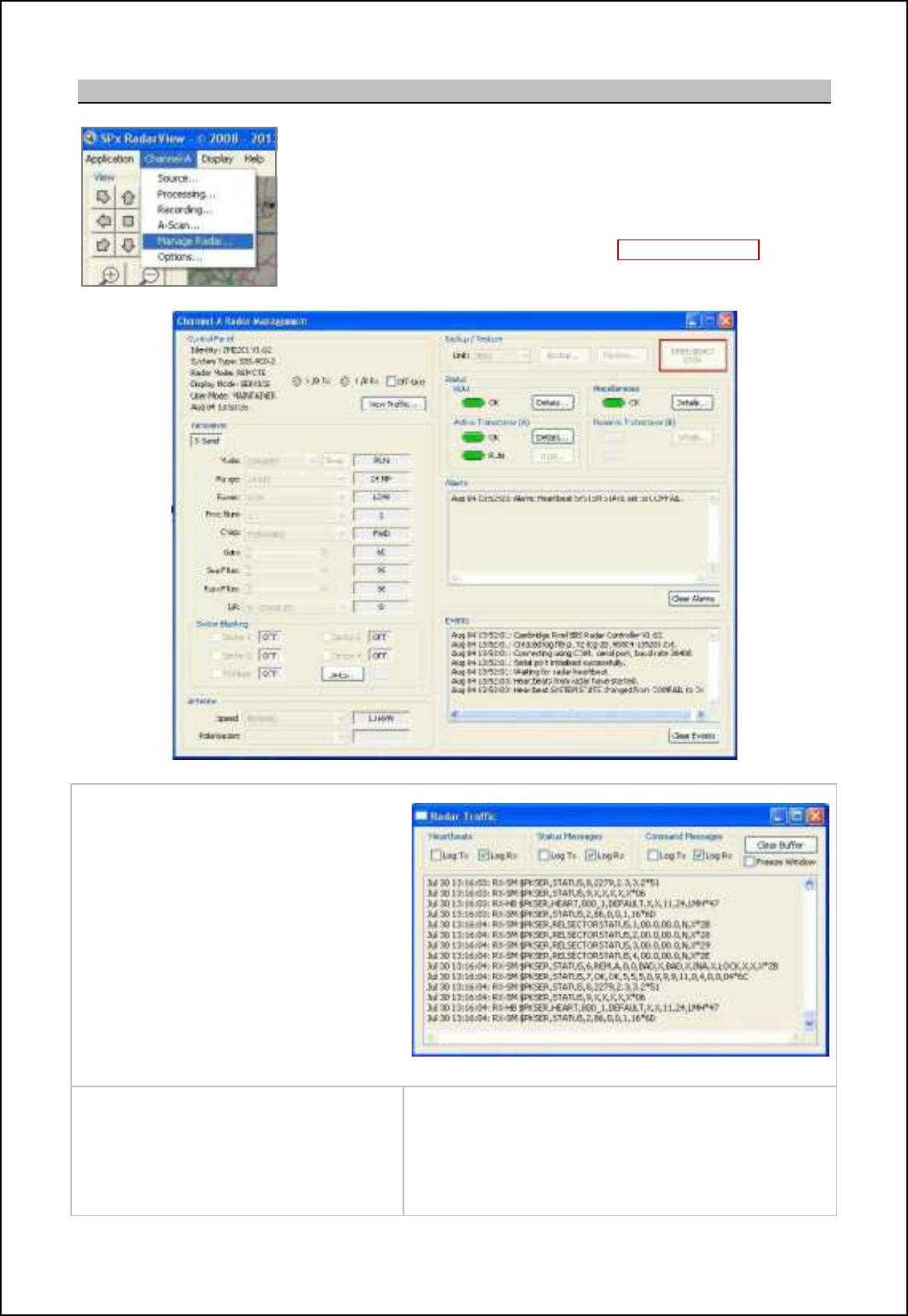
SBS-900 Shore Based Radar Systems
Chapter 8: Service display/ RadarView control
KH-1602-2 issue 1: Standard SBS900 Systems Operator & Maintenance Handbook
Page 81 of 240
8.10.2 RadarView pmanage radar
Selecting •Channel-9 , ETaTZX JTWTeor opens the Manage Radar
screen which allows the remote control and viewing of:
-The Radar Distribution Unit (RDU).
-Transceivers.
-System information.
The screen also allows the activation of the Emergency Stop function.
Each section is detailed on the following pages.
Control Panel
-View system information (software
version etc.).
-H/B: Shows the transmitted and
received Heartbeats (flashes green).
-Off-line:Select to take the service
display Off-line.
-N\Xj LeTYY\Vo: Opens a new window
showing the messages flowing
between the service display and the
RDU.
View Traffic window
Transceiver
Shows the current transceiver settings.
Antenna
Shows the current antenna speed.
Sector Blanking
Shows the status of blanking sectors & Mute ON/ OFF.
Tune
Shows the current tune level
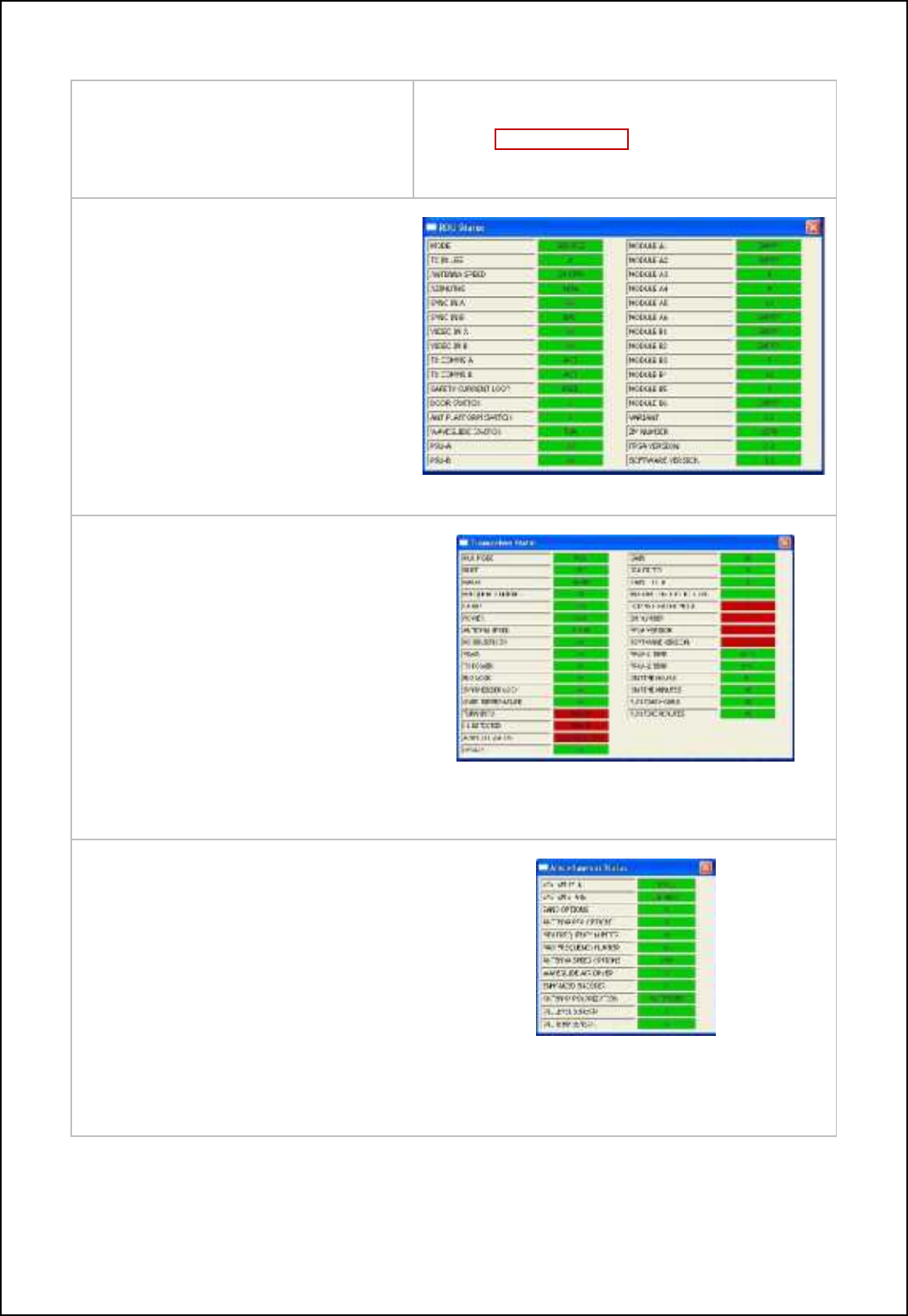
SBS-900 Shore Based Radar Systems
Chapter 8: Service display/ RadarView control
KH-1602-2 issue 1: Standard SBS900 Systems Operator & Maintenance Handbook
Page 82 of 240
Backup & Restore
Backup or restore the RadarView settings.
Emergency Stop
Selecting Emergency Stop sends an antenna/
trasnmission stop command to the RDU. All AC power
is removed from the transceiver/ gearbox.
Status pRDU
Select the 8Q_MUW^f button for information.
Status Green: No fault conditions exist.
Status Red: A fault condition is present.
RDU rDetailsps
Status pActive or Reserve Transceiver
Select the 8Q_MUW^f button for information.
Status Green: No fault conditions exist.
Status Red: A fault condition is present.
Example of the Active Transceiver window
Status pMiscellaneous
Select the 8Q_MUW^f button for information.
Status Green: No fault conditions exist.
Status Red: A fault condition is present.
Example of Miscellaneous status
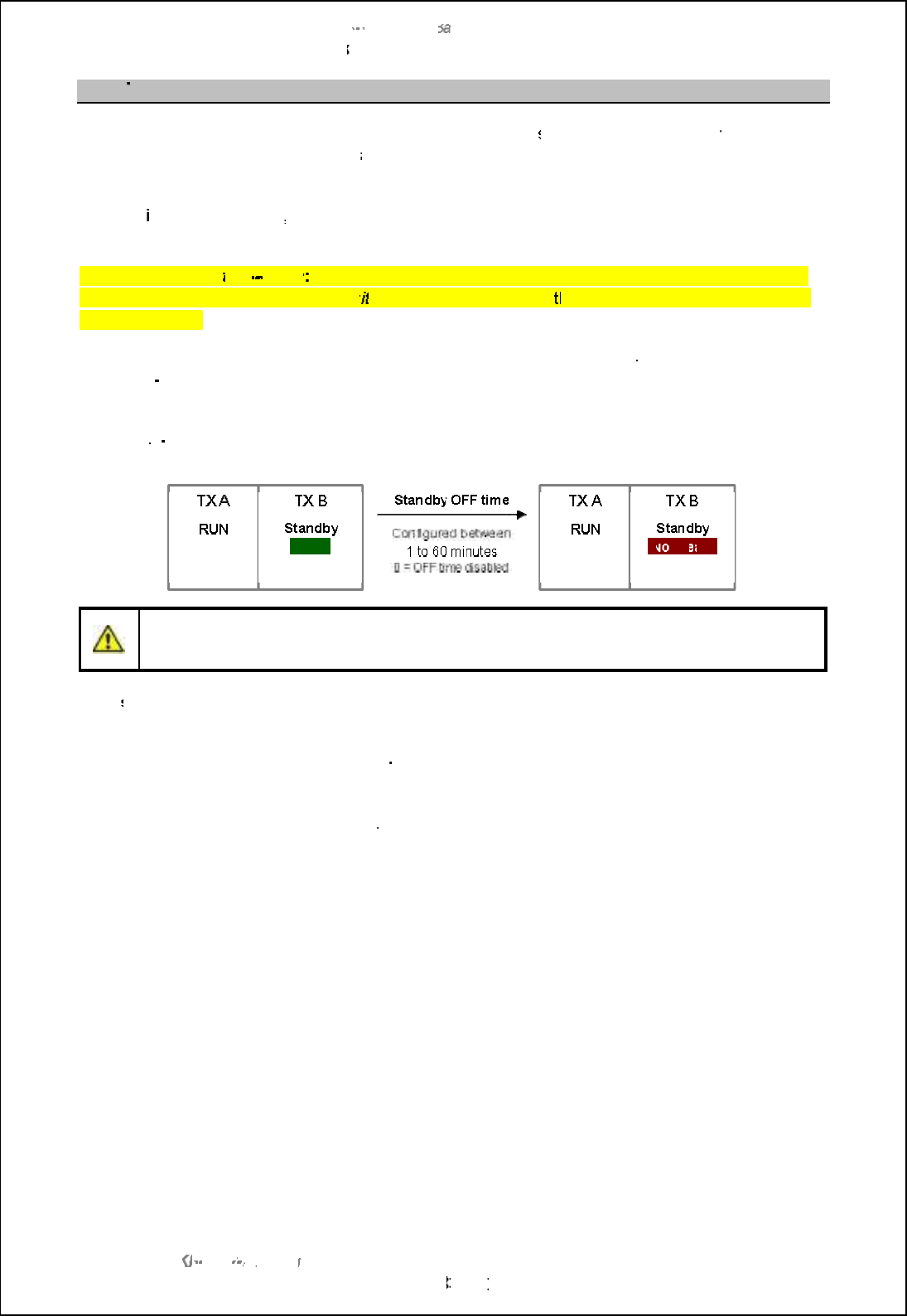
SBS
-
900 Shore
Ba
Ba
sed
Radar Systems
Chapter
8
:
Service display/ RadarView control
KH
KH
-
1602 2
issue 1
:
Standard SBS900 Systems Operator & Maintenance Handbook
Page
83
83
of
240
8.10.3
Transceiver status
Transceiver warm up:
At switch ON, the transceiver enters a
short initialisation period
where the
transceiver(s) will show as
Not Ready
and the TX status indicator in the RadarView software will show
as Red.
After the
initialisation period
, the TX status indicator changes to Green signifying that the transceiver
is ready for use.
Magnetron heater
turn
down
The system is shipped with the magnetron heaters configured to be
The system is shipped with the magnetron heaters configured to be
always ON, i.e. when the system is
swi
tched ON
and in
Standby
the transceiver remains in a
Ready
Ready
state indefinitely.
During commissioning it is possible to set the magnetron heaters to switch OFF when set to Standby
after a pre
determined time. When the heaters are OFF, the transceiver is Not
Ready and the 90
second delay would be required before the unit becomes available for use.
Heater
turn
-
down/ Standby OFF delay may be a site requirement to preserve the life of the
magnetron.
Caution:
The RadarView software DOES NOT report when the heaters have switched
OFF and will continue to show the transceiver as Ready (green).
If the
system is swapped to a transceiver that has been switched OFF, there will be a 90 second
delay whilst the transceiver warms up.
View heater time:
To view the heater turn
-
down time, select the following menus on the LCD display
of the transceiver(s):
-
Defaults / Heater / SBY OFF delay:
Available values are 0 (disabled) to 60 minutes.
Ready
No
No
t Re
ady

SBS-900 Shore Based Radar Systems
Chapter 8: Service display/ RadarView control
KH-1602-2 issue 1: Standard SBS900 Systems Operator & Maintenance Handbook
Page 84 of 240
Page intentionally blank

SBS-900 Shore Based Radar Systems
Chapter 9: Planned maintenance
KH-1602-2 issue 1: Standard SBS900 Systems Operator & Maintenance Handbook
Page 85 of 240
9 Planned maintenance
9.1 Standard Antenna Systems
Equipment: The following pages detail the monthly, annual, 3 and 5-year planned
maintenance schedules for the following Standard antenna sub-systems.
LPA-A37
LPA-A55
LPA-A3
LPA-A455
X and S-band Low Profile Antennas (all variants)
DTX-A3
GTX-A11
DTX-A19 X and S-band gearboxes (all variants)
DTX-A7 Downmast transceiver enclosure (all variants)
SBS-A1 RDU - Radar Distribution Unit (all variants)
55-100-0436-001 Static desiccator
Recommended maintenance schedule:
Annual:
(General inspection and cleaning of the system
(Fan checks
(Safety checks
3-year: (Replacement of gearbox oil
5-year: (Replacement of static inverter and RDU power supply fans
Maintenance record: The following pages have been designed to be printed, completed and stored
as a maintenance record for standard systems.
Any damage that is identified as part of an inspection should immediately be
reported to Kelvin Hughes and appropriate action taken to prevent further
damage occurring.
Procedure: Prior to carrying out any maintenance the system must be fully isolated from
all sources of AC power including any UPS supported supplies, the required
maintenance task(s) should be undertaken and on completion, the power
restored and the system fully tested.
Spares: Where required, only Kelvin Hughes approved spares must be used. The use
of unapproved spares invalidates the warranty status of the unit could lead to
a malfunction of the system.
Adverse weather: It is strongly recommended that the gearbox inspections noted in Annual
Maintenance procedures are carried out at the earliest safe opportunity after
the system has been exposed to severe or adverse weather conditions.
Health & safety: All safety warnings for the system noted in section 2 must be observed at all
times when working on, inspecting or maintaining any part of the system or
its associated sub systems.
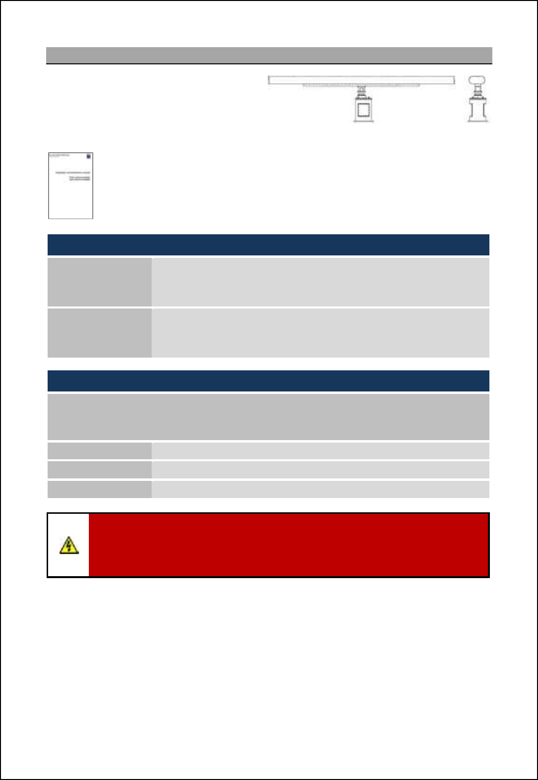
SBS-900 Shore Based Radar Systems
Chapter 9: Planned maintenance
KH-1602-2 issue 1: Standard SBS900 Systems Operator & Maintenance Handbook
Page 86 of 240
9.2 Advanced Antenna Systems
The planned maintenance procedures for the
Advanced ST1-F10/ 20 Antenna Turning Unit
(ATU) and antenna range are briefly outlined
below but are not detailed in this handbook.
ST1-F10/ 20 Antenna Turning Unit & antenna
Please refer to the installation and maintenance handbook supplied with the advanced
equipment for full details on planned maintenance.
Electronic copies of these handbooks (Pdf) are available on request.
For reference use only, the recommended maintenance schedule is:
Recommended maintenance schedule for ATU and antenna:
Every 6 months: (General inspection of the ATU and the antenna.
Every 6 years:
(Replacement of the crossed roller bearing of the bearing-mounted
antenna mounting flange.
(Replacement of the gearbox complete with motor
(Replacement of the rotary joint.
Transceiver enclosure and Radar Distribution Unit:
The transceiver enclosure and Radar Distribution Unit MUST be inspected in line with the
Standard system planned maintenance schedule which is shown in the following section.
This includes the inspection of the following equipment:
DTX-A7 Downmast transceiver enclosure (all variants)
SBS-A1 RDU - Radar Distribution Unit (all variants)
55-100-0436-001 Static desiccator
WARNING:
Lethal voltages are present within the equipment.
All maintenance procedures must be carried out with all relevant power sources switched
OFF, fully isolated and disconnected.
Health & Safety precautions: All health & safety notices noted in this document and the enhanced
system handbook must be read and observed at all times.
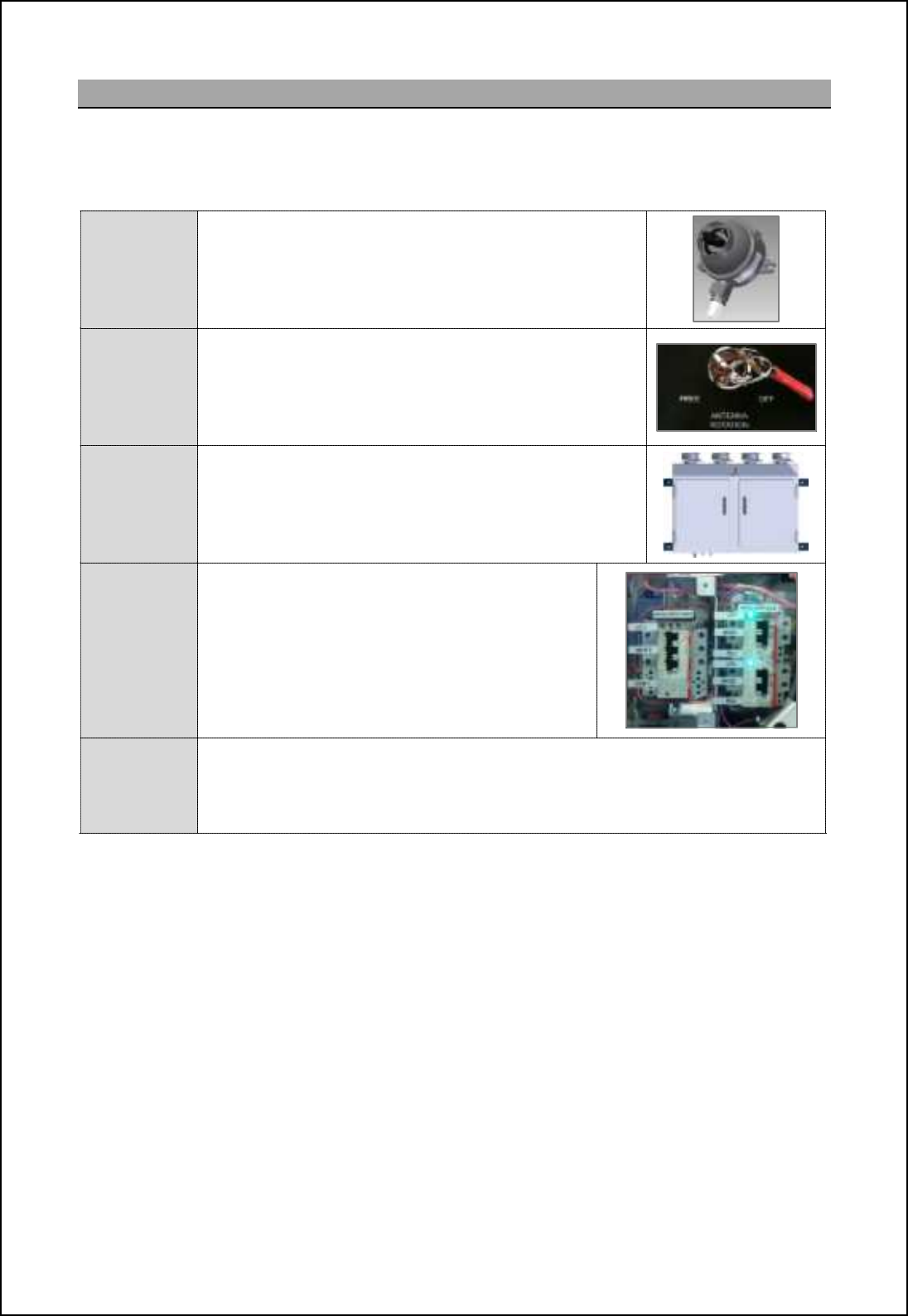
SBS-900 Shore Based Radar Systems
Chapter 9: Planned maintenance
KH-1602-2 issue 1: Standard SBS900 Systems Operator & Maintenance Handbook
Page 87 of 240
9.3 System isolation
In addition to the normal health and safety requirements, the system must be made safe prior to
carrying out any maintenance task by fully isolating all AC power including any UPS supported
supplies to the system as shown below:
Man aloft
switch
(MAS)
As an additional safety precaution, the Man Aloft Switch
can be placed into the OFF position.
This acts as a backup safety measure to removing the
Antenna Rotation keyswitch.
RDU
Antenna
rotation
switch
Place the Antenna Rotation keyswitch on the front of the
Radar Distribution Unit into the OFF position.
The key should be removed and retained until the
maintenance task being undertaken has been completed.
DTX-A7
Transceiver
enclosure
Ensure that the AC breaker(s) located within the
transceiver enclosure are in the OFF position.
Note: Sb_ KDCm ih _[]b \l_[e_l [l_ cffogc[n_^ qb_h @B
supplies are still connected to the transceiver enclosure.
RDU
AC power
Within the Radar Distribution Unit, ensure all
breakers are in the OFF position.
Note: Vb_h mqcn]b_^ NEE+ nb_ KDCm ih _[]b
breaker remain illumiated indicating that AC
supplies are still connected to the RDU.
External AC
Isolate and disconect ALL single and 3-phase AC supplies to the Radar
Distribution Unit including all UPS supported supplies and physically remove all
power sockets.
The system is now fully isolated from all sources of AC supply.
SBS-900 Shore Based Radar Systems
Chapter 9: Planned maintenance
KH-1602-2 issue 1: Standard SBS900 Systems Operator & Maintenance Handbook
Page 88 of 240
9.4 Annual maintenance procedure
SBS-900 Annual planned maintenance record sheet Inspection sheet
1 of 10
Equipment details
Antenna Sub-System
Note
Gearbox/ Antenna Turning Unit Antenna
Part No. Part
No.
Serial
number: Serial
No.
Transceiver enclosure
Part number DTX-A7-
Serial
number(s)
Radar Distribution Unit (RDU)
Part number SBS-A1-
Serial
number(s)
Man Aloft Switch (MAS)
Part number SBS-A132
Serial
number
Inspection
date:
(DD/ MM/ YYYY)
Inspected by: Print: Sign:
Tools
required
'Blower or soft brush.
'Medium flat head screwdriver (for opening RDU and transceiver enclosure).
'Mild detergent
Note: Do not use abrasive cleaners or products containing alcohol.
'Soft abrasive free cloth.
'Safety ohmmeter, bridge Megger or Multimeter.
'Spanners (6mm, 10mm and as required for custom earth attachments).
'Wire brush or emery cloth.
Skill level Basic electrical training, working at heights awareness.
Time Approximately three hours depending on equipment location and accessibility
Note - Advanced ATU and antennas: Please refer to the advanced installation and maintenance
handbook supplied with the equipment for full details on planned
maintenance of advanced equipment.
The maintenance procedure for the Advanced antenna sub-system
is NOT covered or recorded in this document.
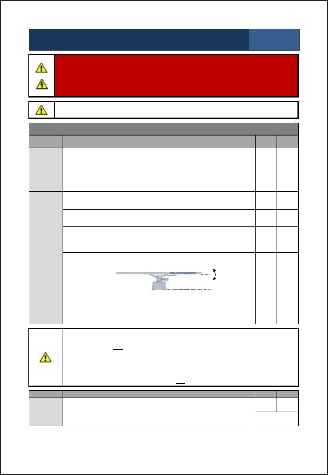
SBS-900 Shore Based Radar Systems
Chapter 9: Planned maintenance
KH-1602-2 issue 1: Standard SBS900 Systems Operator & Maintenance Handbook
Page 89 of 240
SBS-900 Annual planned maintenance record sheet Inspection sheet
2 of 10
WARNING: Prior to commencing any maintenance procedure, users must familiarise themselves
with the health & safety warnings noted in the planned maintenance and health and safety sections
of the system handbooks.
Prior to carrying out planned maintenance, the system must be fully isolated from ALL single and 3-
phase AC supplies including any UPS supported supplies.
Caution: When the gearbox and antenna have been operating in strong sunlight or elevated
temperatures, the gearbox casing and antenna surfaces will be extremely hot.
Antenna inspection
Task Description Pass Fail
Cleaning
Clean the antenna facia with a soft cloth moistened in a mild non-
abrasive soap solution.
Note1: Cleaning the antenna is important as the system performance can be
degraded if the antenna transmission face becomes obscured by dirt.
Note2: The antenna facia must never be painted.
' '
Physical
inspection
Ensure that all securing bolts are tights, secure and show no signs of
severe corrosion or damage. ' '
Check that waveguide couplings are securely fastened and appear to
be waterproof. ' '
The antenna should be checked to ensure that there is no obvious
external damage, cracking or potential faults that could lead to a
general failure of any part of the system.
' '
Check the antenna for signs of excessive vertical end play.
Example of antenna end-play
If the end play is more than +/-10mm please consult with Kelvin
Hughes.
' '
Caution:
'The following tests should only be undertaken when it is safe to manually rotate the antenna
i.e. the system is fully isolated from all sources of power and the antenna can be safely
accessed and reached.
'Do not use excessive force.
'Do not take unnecessary risk when turning the antenna such as reaching too far or leaning
outside safety guardrails.
'This task should be disregarded if there are any safety concerns.
Task Description Pass Fail
Manual
antenna
rotation
Noting the above safety precautions and where safe to do so,
manually rotate the antenna and ensure that it is free from obstruction
and turns smoothly
' '
Antenna
not
accessible '

SBS-900 Shore Based Radar Systems
Chapter 9: Planned maintenance
KH-1602-2 issue 1: Standard SBS900 Systems Operator & Maintenance Handbook
Page 90 of 240
SBS-900 Annual planned maintenance record sheet Inspection sheet
3 of 10
Gearbox inspection
Task Description Pass Fail
General
cleaning Clean all exterior surfaces with a soft, cloth moistened in a mild non-
abrasive soap solution. ' '
Physical
inspection
Ensure that all securing bolts for the gearbox and antenna are secure
and show no signs of severe corrosion or damage. Pay particular
attention to the bolts that hold the gearbox assembly onto the
mounting plate.
' '
Inspect the gearbox including all mounting points for any signs of
stress damage.
Severe weather: This inspection should be carried out at the earliest
safe opportunity after the system has been exposed to severe or
adverse weather conditions.
' '
Check that cable glands, cable entries and waveguide couplings are
securely fastened and appear to be waterproof. ' '
Within reason and where safe to do so, check all accessible or
exposed cables for any signs of damage and ensure they are safely
secured into/ onto cable trays or trunking.
' '
The system should be checked to ensure that there is no obvious
external damage or potential fault conditions that could lead to a
general failure of any part of the system.
' '
Check for any signs of oil leaks from the gearbox assembly. ' '
Earth
bonding
and
continuity
Ensure that the earth bonding nuts and bolts are tight and free from
corrosion.
If corrosion is present, clean and re-terminate as described in section
9.7 page 114.
' '
Test the earth bonding conductivity by attaching one lead of the test
equipment note1 to earth/ chassis and the other to an unpainted part of
the equipment under test.
Check earth bonding for continuity, the resistance should not exceed
0.1 ohms. If a test fails, investigate the bonding, rectify (see section
9.7 page 114) and repeat the test.
Note1:Safety ohmmeter, bridge Megger or Multimeter.
' '

SBS-900 Shore Based Radar Systems
Chapter 9: Planned maintenance
KH-1602-2 issue 1: Standard SBS900 Systems Operator & Maintenance Handbook
Page 91 of 240
SBS-900 Annual planned maintenance record sheet Inspection sheet
4 of 10
Radar Distribution unit (RDU)
Task Description Pass Fail
Cleaning
External
surfaces Clean with a soft, non-abrasive cloth moistened in a mild
soap solution. ' '
Internal
surfaces
Open the door of the Radar Distribution Unit using a
screwdriver. Carefully clean out the unit using blower
and
/ or
soft brush.
' '
Physical
inspection
External
Ensure that all mounting bolts are secure. ' '
Ensure all connectors are securely in place; inspect
internal cabling for condition and wear. ' '
Check that all air vents are clear of obstructions and
dust. ' '
Internal
Dhmol_ [ff OBAm [h^ ]ihh_]nilm [l_ m_]ol_fs ch jf[]_;
inspect internal cabling for condition and wear. ' '
Check that all air vents and fans are clear of obstructions
and clear of dust accumulation. ' '
General
The system should be checked to ensure that there is no
obvious internal, external damage or potential fault
conditions that could lead to a general failure of any part
of the system.
' '
Earth
bonding
and
continuity
On the underside of the RDU, visually inspect the earth terminal for
damage and corrosion.
If corrosion is present, clean and re-terminate as described in section
9.7 page 114.
' '
Check that the earth bonding strap between the RDU door and
chassis is present, clean and re-terminate as described in section 9.7
page 114.
' '
Test the earth bonding conductivity by attaching one lead of the test
equipment note1 to earth/ chassis and the other to an unpainted part of
the equipment under test.
Check the earth bonding for continuity, the resistance should not
exceed 0.1 ohms. If a test fails, investigate the bonding, rectify and
repeat the test.
Note1:Safety ohmmeter, bridge Megger or Multimeter.
' '

SBS-900 Shore Based Radar Systems
Chapter 9: Planned maintenance
KH-1602-2 issue 1: Standard SBS900 Systems Operator & Maintenance Handbook
Page 92 of 240
SBS-900 Annual planned maintenance record sheet Inspection sheet
5 of 10
DTX-A7-xx Transceiver enclosure
Task Description Pass Fail
General
cleaning Clean all exterior surfaces with a soft cloth moistened in a mild non-
abrasive soap solution. ' '
Physical
inspection
Ensure that all securing bolts are secure and show no signs of severe
corrosion, damage. Pay particular attention to the main chassis
supporting bolts.
' '
Inspect the unit including all mounting points for any signs of stress
damage.
Severe weather: This inspection should be carried out at the earliest
safe opportunity after the system has been exposed to severe or
adverse weather conditions.
' '
Check that cable glands, cable entries and waveguide couplings are
securely fastened and appear to be waterproof. ' '
Within reason and where safe to do so, check all accessible or
exposed cables for any signs of damage and ensure they are safely
secured into/ onto the cable tray or trunking.
' '
The system should be checked to ensure that there is no obvious
external damage or potential fault conditions that could lead to a
general failure of any part of the system.
' '
Check that the four wind turned rotary ventilators mounted on top of
the assembly are free from dust and obstructions and can rotate
freely.
' '
Check that no moisture or water is present within the enclosure. ' '
Static
Desiccator
The sachets in the static Desiccator must be changed every 12
months.
The two sachets are within the desiccator which is located on the
base of the enclosure or on earlier units between the two front access
doors.
Used/ removed sachets must be disposed of in accordance with local
disposal regulation.
When the sachets have been replaced, ensure that the desiccant
enclosure cap is securely in position and fully tightened.
Replacement sachet: 55-100-0494-002 Notes
Sachet shelf life: 2-years
Notes:
-The part number noted above is for 1 sachet, two are required.
-Split or torn sachets must not be used.
-Replacements must be from a sealed package (replacements have a shelf life of 2-
years).
-Two sachets MUST be used.
' '
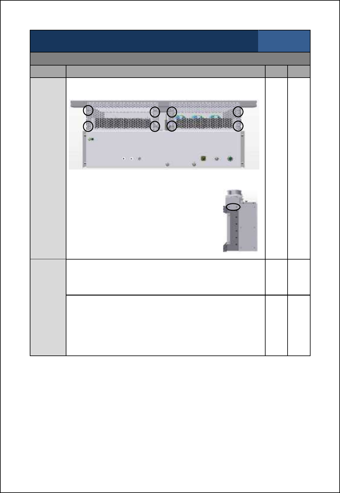
SBS-900 Shore Based Radar Systems
Chapter 9: Planned maintenance
KH-1602-2 issue 1: Standard SBS900 Systems Operator & Maintenance Handbook
Page 93 of 240
SBS-900 Annual planned maintenance record sheet Inspection sheet
6 of 10
Transceiver enclosure
Task Description Pass Fail
Base
plate air
baffle
The air baffle plates located on the base of the Transceiver Enclosure
should be checked and cleaned as necessary.
Base of DTX-A7 Transceiver Enclosure
Each baffle is retained by 4 cross-head screws as indicated above.
' '
The plates should be removed and any dust or
foreign objects removed from the plate and the
heatsinks above using a brush or blower.
If necessary, the ducted fans on the top of the unit
can also be removed to assist in cleaning the
heatsink void.
These are retained by two crosshead screws at
either end of the enclosure. Side view of DTX-A7
Earth
bonding
and
continuity
Ensure that the earth bonding nuts and bolts are tight and free from
corrosion.
If corrosion is present, clean and re-terminate as described in section
9.7 page 114.
' '
Test the earth bonding conductivity by attaching one lead of the test
equipment note to earth/ chassis and the other to an unpainted part of
the equipment under test.
Check earth bonding for continuity, the resistance should not exceed
0.1 ohms. If a test fails, investigate the bonding, rectify (see section
9.7 page 114) and repeat the test.
Note: Safety ohmmeter, bridge Megger or Multimeter.
' '
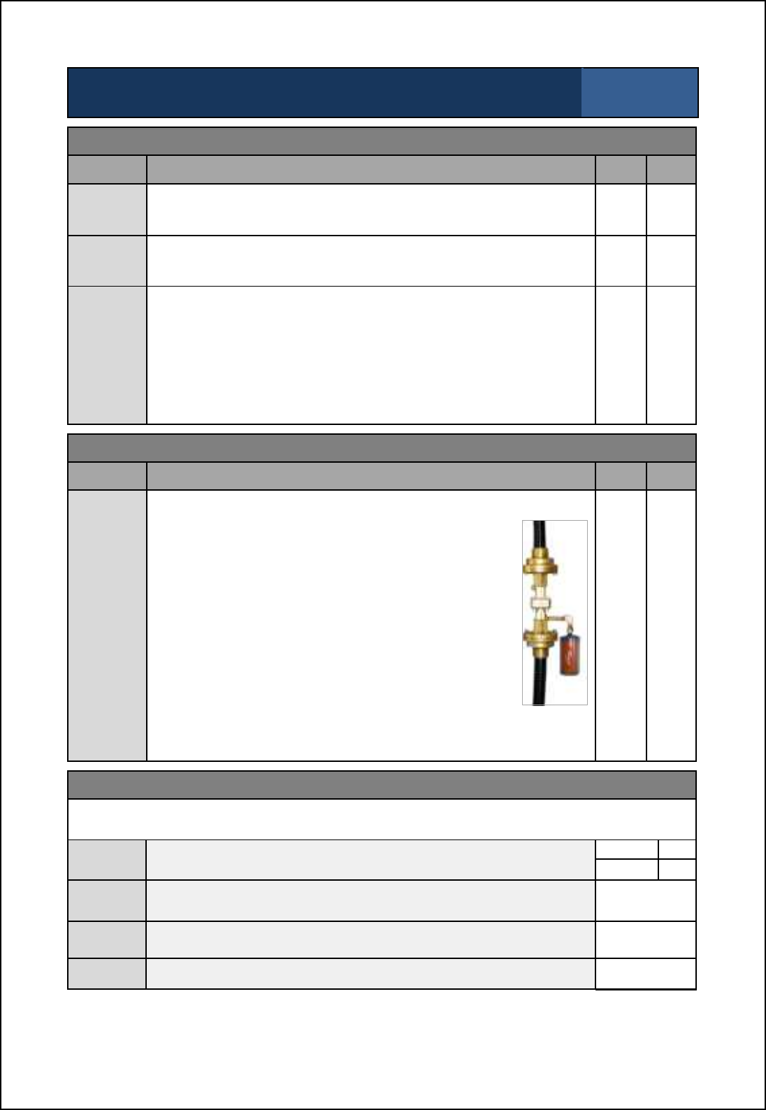
SBS-900 Shore Based Radar Systems
Chapter 9: Planned maintenance
KH-1602-2 issue 1: Standard SBS900 Systems Operator & Maintenance Handbook
Page 94 of 240
SBS-900 Annual planned maintenance record sheet Inspection sheet
7 of 10
Man aloft switch
Task Description Pass Fail
Physical
inspection Ensure that all fastenings are secure and show no signs of severe
corrosion or damage. ' '
Switch
action Ensure the switch operation is smooth and that both the Free and
OFF positions can be selected. ' '
Earth
bonding
and
continuity
Test the earth bonding conductivity by attaching one lead of the test
equipment note1 to chassis/ earth and the other to an unpainted part of
the equipment under test.
Check the earth bonding for continuity, resistance should not exceed
0.1 ohms. If test fails, investigate the bonding, rectify and repeat the
test.
Note1:Safety ohmmeter, bridge Megger or Multimeter.
' '
55-100-0436-001 Static desiccator
Task Description Pass Fail
Physical
inspection
The clear wall of the static desiccator unit allows visual
inspection of the desiccant condition.
As moisture is adsorbed the desiccant colour will change
to either:
Deep blue (dry) to pink/white (wet).
or
Orange (dry) to purple (wet).
When 80% of the desiccant material has changed
colour, the unit should be replaced.
To prevent moisture from entering the breather hole, the
ohcn gomn \_ l_jf[]_^ [m mbiqh qcnb nb_ •hih-`cnncha _h^
that contains the breather hole pointing downwards.
Maintenance frequency note: In areas of high humidity it may be
necessary to increase the inspection period of the desiccant.
Static
Desiccator
' '
Restore power to the system
On completion of the above maintenance tasks and noting that the following will cause antenna
rotation and system transmission, restore power to the system.
Security
switches Place the Antenna rotation and man aloft switches in the FREE
positions.
Antenna
rotation
'
Man aloft '
AC
Breakers Switch the single and three-phase breakers within the RDU ON.
Caution: This will cause the antenna to rotate '
Remote
control Place the Remote/ Local switch on the RDU to the Local position. '
Test Test the system and ensure full functionality. '

SBS-900 Shore Based Radar Systems
Chapter 9: Planned maintenance
KH-1602-2 issue 1: Standard SBS900 Systems Operator & Maintenance Handbook
Page 95 of 240
SBS-900 Annual planned maintenance record sheet Inspection sheet
8 of 10
Powered tests: Safety switch tests
The following tests should be carried out with power restored to the system.
Caution: When carrying out the following test, do not contravene any health and safety
precautions regarding working aloft, antenna or electrical safety.
The following tests will Stop and Start antenna rotation and system transmission. The area around
the antenna must be kept clear at all times during these tests.
Task Description Pass Fail
Antenna
Rotation
keyswitch
(RDU)
- Set the system to RUN so that it is transmitting and the antenna
is rotating.
- Place the Antenna Rotation keyswitch (located on the door of
the Radar Distribution Unit) into the OFF position.
Remove and RETAIN the key.
- The yellow LED on the front panel of the Radar Distribution Unit
will flash.
- Ensure that the system has stopped transmitting, that antenna
rotation has stopped and that the appropriate system alarms are
generated.
' '
Man aloft
switch
(MAS)
- Where safe to do so, change the Man Aloft switch to the OFF
position.
- Reinsert the key into the Antenna Rotation Keyswitch and set to
FREE.
- As the Man Aloft Switch is OFF the system should not transmit
and the antenna rotation should not rotate.
- Place the Antenna Rotation keyswitch back to the OFF position.
Remove and RETAIN the key.
' '
Man aloft
switch
& Antenna
Rotation
keyswitch
- Change the Man Aloft switch to the FREE position.
- Reinsert the key into the Antenna Rotation Keyswitch and set to
FREE.
-Ensure system transmission and antenna rotation commence.
' '
Hut door
switch
Where fitted
- Open the hut door.
- Ensure the appropriate system alarm is generated at the RDU.
- Close the HUT door.
' '
Not fitted '
Antenna
platform
switch
Where fitted
- Where it is possible and SAFE to do so, open the antenna
platform access door.
- Ensure the appropriate system alarm is generated at the RDU.
- Close the antenna platform access door.
' '
Not fitted '
SBS-900 Shore Based Radar Systems
Chapter 9: Planned maintenance
KH-1602-2 issue 1: Standard SBS900 Systems Operator & Maintenance Handbook
Page 96 of 240
SBS-900 Annual planned maintenance record sheet Inspection sheet
9 of 10
Powered tests: Cooling fan checks
The following tests require access to the internal electronics within the Radar Distribution Unit and
the transceiver enclosure.
Caution: Lethal AC, DC and high voltages are present within the system. Exercise
extreme caution when carrying out the following checks.
RDU: There are two fans mounted within the RDU on the power supply assembly:
Task Description Pass Fail
Antenna
isolation Isolate the 3-phase supply to the Radar Distribution Unit. ' '
RDU
fan
operation
- Open the door to the RDU.
- Visually confirm that the two fans on the dual redundant power
supply are running.
' '
Transceiver
enclosure Where fitted, ensure that the SBS-A179 powered fan kits are
operational.
' '
Not fitted '
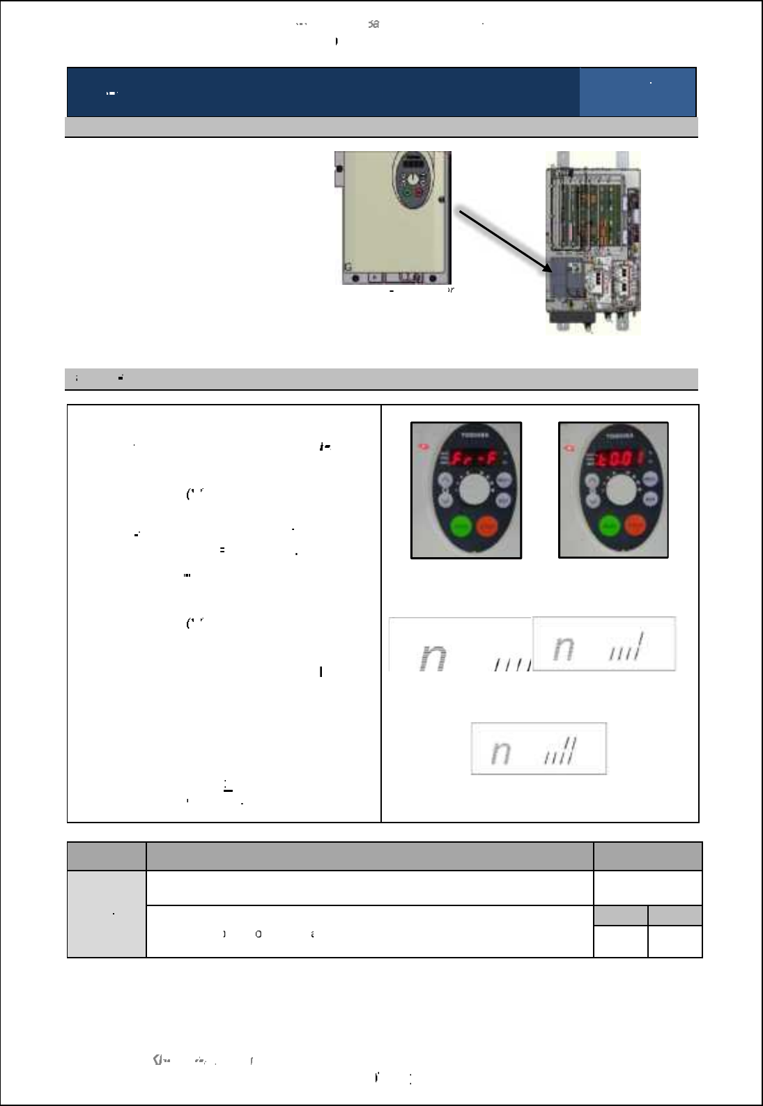
SBS
-
900 Shore
Ba
Ba
sed
Radar Systems
Chapter
9
:
Planned maintenance
KH
KH
-
1602 2
issue 1
:
Standard SBS900 Systems Operator & Maintenance Handbook
Page
97
97
of
240
SBS
900
Annual
planned maintenance
record sheet
Inspection sheet
10 of 10
Fan condition check
The
fan within the static inverter
located within the Radar
Distribution Unit has a service life
of approximately 30,000 hours.
The fan run time must be checked
and the fan replaced where
necessary.
Toshiba VF
S11 inverter
Radar distribution unit
F
an run
time
-
On the static inverter control panel press the
MODE
button twice and ensure that
Fr
Fr
F
is
displayed
-
Press the down (
$
) button once and the
cumulative operating hours will be
displayed.
The run
time will be indicated by
Tx.xx where:
T0.01
= 1 hour,
t1.00
= 100 hours
Record the run
-
time and proceed to the
next step
-
Press the down (
$
) button again and 4
single
height
lines should be shown:
The fan should be changed when the
last line
changes to a double height line:
If any of the first three lines are double height,
this indicates a potential fault condition within
the inverter which should be replaced.
If the recorded time is
>
30000
(t300.00)
hours
the fan must be
changed
Inverter display
Fan OK
Change fan
Inverter display
Change inverter
Task
Description
Result
Fan
condition
check
Inverter fan run time
(e.g. t0.50)
Fan inverter OK or Change fan
Please refer to
the C
orrective
M
aintenance
section
for details on changing the
inverter
fan.
Fan OK
Change
Change
fan
'
'
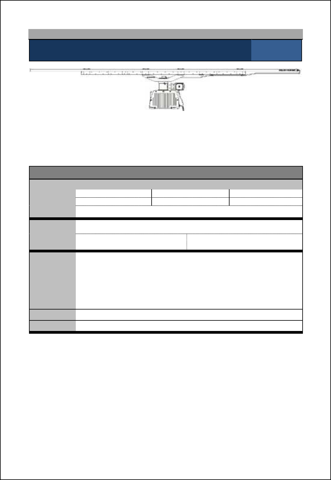
SBS-900 Shore Based Radar Systems
Chapter 9: Planned maintenance
KH-1602-2 issue 1: Standard SBS900 Systems Operator & Maintenance Handbook
Page 98 of 240
9.5 3-year maintenance
3-year maintenance:
Changing gearbox oil (Standard systems only) Inspection sheet
1 of 2
Kelvin Hughes DTX-A3-xxxx gearbox and antenna
After three years of use, the oil in the standard gearbox should be changed:
Advanced Antenna Turning Unit and antenna: Please refer to the installation and maintenance
handbook supplied with the equipment for full details on planned maintenance.
Equipment details
Transceiver/ gearbox
Part number: DTX-A3-AXZX 'GTX-A11 'DTX-A19 '
DTX-A3-BXZX 'GTX-A11-BAAA 'DTX-A19-BAAA '
Serial number:
Oil change
date: (DD/ MM/ YYYY)
Changed by: Print: Sign:
Tools required
'5mm across flats hexagonal wrench/ Allen key.
'Suitable syringe or equivalent with small pipe attached for reaching into
gearbox.
'Suitable container to hold at least 200ml of oil.
'Mineral oil ARAL DEGOL BG320 quantity 200 ml.
Kelvin Hughes Part No. 55-100-0391-001
'Protective gloves.
Skill level Basic electrical and mechanical training, working at heights awareness.
Time Less than two hours depending on equipment location and accessibility
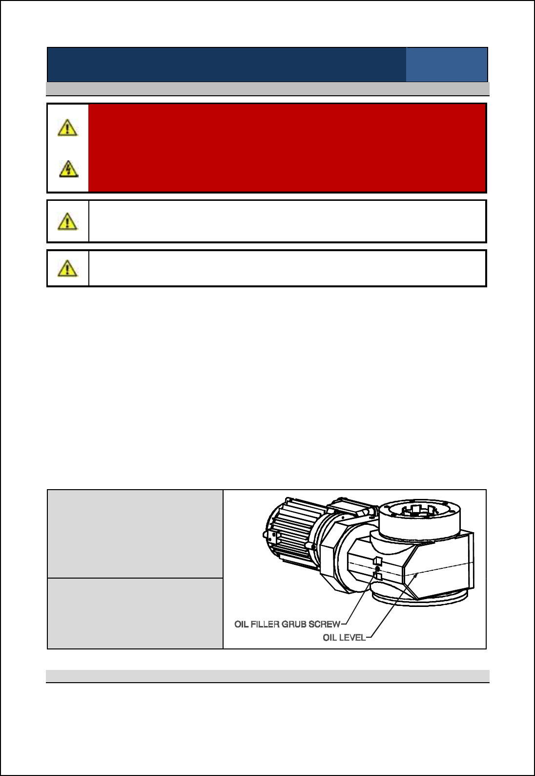
SBS-900 Shore Based Radar Systems
Chapter 9: Planned maintenance
KH-1602-2 issue 1: Standard SBS900 Systems Operator & Maintenance Handbook
Page 99 of 240
3-year maintenance:
Changing gearbox oil (Standard systems only) Inspection sheet
2 of 2
Health & safety precautions
WARNING: Prior to commencing any maintenance procedure, users must familiarise
themselves with the health & safety warnings noted in the planned maintenance and
health and safety sections of the system handbooks.
AC power: Prior to carrying out any planned maintenance, the system must be fully
isolated and disconnected from all sources of single and 3-phase supply including any
UPS supported supplies.
Caution: When the transceiver, gearbox and antenna have been operating in strong
sunlight or elevated temperatures, the gearbox casing and antenna surface will be
extremely hot.
Gearbox: Under no circumstances should any attempt be made to remove the motor from the
gearbox or the gearbox from the main chassis as this will lead to major loss of oil and damage to
the sealing gaskets.
Gloves: Protective gloves must be worn at all times when the changing oil in the gearbox.
CoSHH: Please refer to the CoSHH (Control of Substances Hazardous to Health)sheet
supplied with the oil for information on the oil including hazard identification, first aid,
fire precautions and disposal recommendations.
Temperature: Due to the pour point of the oil, this task should not be carried out when the ambient
temperature is below -15 deg C.
Oil: When the gearbox has been operating in elevated temperatures, the oil removed
from the gearbox may be hot.
Disposal: Oil removed from the gearbox must be disposed of in accordance with local waste
disposal regulations.
Drain/ filler hole
Remove and carefully retain the 5mm oil
filler grub screw from the gearbox.
Using a syringe or equivalent and a
suitable container which will hold at least
200ml, remove as much oil as is possible
from the gearbox.
Refill
Refill with the specified oil using a suitable
syringe or equivalent.
Refill the oil to the level shown opposite.
Refit and tighten the 5mm grub screw.
Completion of task
When the oil has been replaced and the filler grub screw securely replaced, restore power to the
system and ensure that the gearbox and system are fully operational.
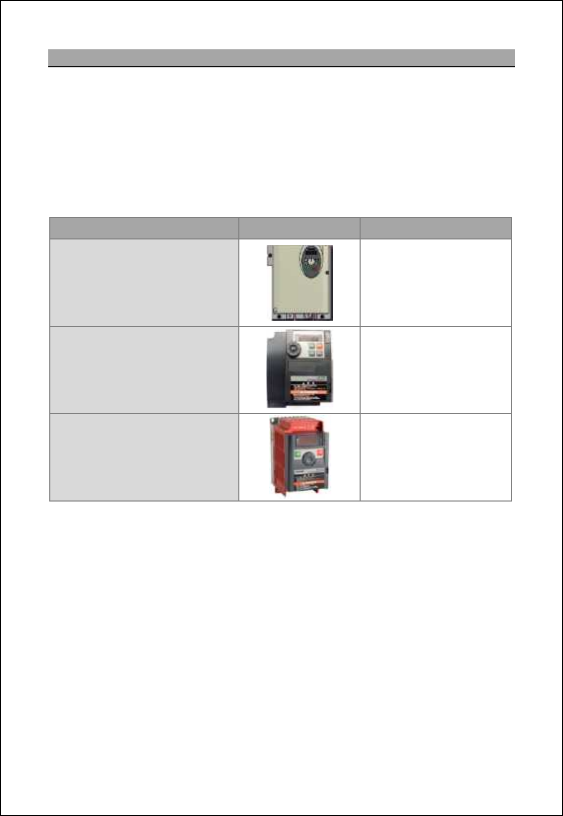
SBS-900 Shore Based Radar Systems
Chapter 9: Planned maintenance
KH-1602-2 issue 1: Standard SBS900 Systems Operator & Maintenance Handbook
Page 100 of 240
9.6 5-year maintenance three-phase inverter
The 5-year maintenance schedule depends on the static inverter mounted within the Radar
Distribution Unit.
After 5 or 10-years of use, the static inverter located within the Radar Distribution Unit must be
changed as over time the electrolytic capacitors within the inverter can dry out.
A number of versions of the inverter are available as detailed below.
Visual confirmation of the inverter fitted is strongly recommended prior to commencing the procedure
or obtaining spares.
Manufactures part number Unit detail Replacement schedule
VF-S11 Every 5-years
VF-S15
Note: 440V and 220VAC variants Every 10-years
Vf-nC3 Every 5-years
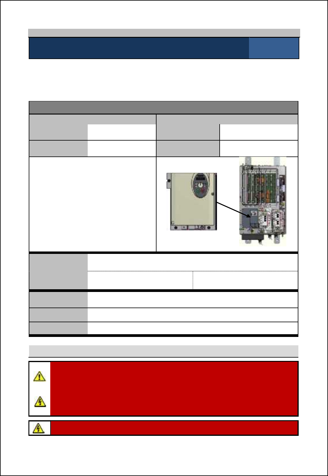
SBS-900 Shore Based Radar Systems
Chapter 9: Planned maintenance
KH-1602-2 issue 1: Standard SBS900 Systems Operator & Maintenance Handbook
Page 101 of 240
9.6.1 5 year maintenance: VF-S11
5-year maintenance: Changing the static inverter in the RDU Inspection sheet
1 of 6
After 5-years of use, the static inverter located within the Radar Distribution Unit must be changed as
over time the electrolytic capacitors within the inverter can dry out.
This maintenance procedure applies to Radar Distribution Units fitted with the inverter detailed below.
Equipment details
Radar Distribution Unit (RDU) Replacement Inverter
Part number SBS-A1- Part number 45-690-0065-001
Serial number Serial number
Toshiba VF-S11
With the exception of the user replaceable
fan, the VF-S11 inverter is a sealed unit that
contains no field serviceable or repairable
parts.
The unit must never be dismantled or
repaired in the field. Toshiba VF-S11 inverter
Radar distribution unit
Inverter
replacement date (DD/ MM/ YYYY)
Changed by Print: Sign:
Tools required A general selection of flat and cross headed screwdrivers.
Skill level Mechanical and electrical training including awareness of single and three
phase AC supplies.
Time Less than two hours depending on equipment location and accessibility
Health and safety
WARNING: Prior to commencing any maintenance procedure, users must familiarise
themselves with the health & safety warnings noted in the planned maintenance and health
and safety sections of the system handbooks.
AC power: Prior to carrying out any planned maintenance, the system must be fully
isolated and disconnected from all sources of single and 3-phase supply including any
UPS supported supplies.
Warning: When powered lethal voltages are present on the terminals and within the
inverter.
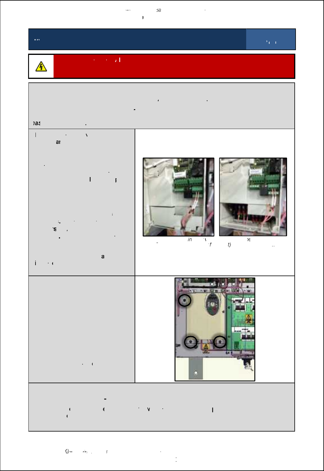
SBS
-
900 Shore
Ba
Ba
sed
Radar Systems
Chapter
9
:
Planned maintenance
KH
KH
-
1602 2
issue 1
:
Standard SBS900 Systems Operator & Maintenance Handbook
Page
102
of
240
5
-
year maintenance:
Changing the static inverter in the
RDU
Inspection sheet
2
of
6
Disconnect the power:
A
ll AC sources
including UPS supported supplies
must be FULLY isolated
and disconnected
from
the Radar Distribution Unit prior to commencing this
or any maintenance
task.
Disconnection:
Ensure
the system is fully disconnected from all
AC
power sources
Disconnect/ unplug PL4
: This is the 3
-
phase supply to the antenna motor and is located on the
base of the Radar Distribution Unit.
This must not be reconnected until the replacement inverter
ha
ha
s been configured
T
he screw terminals
within the
inverter c
a
n be
accessed by opening
the door of the inverter.
The main screw terminals are further
protected by a removable
safety
cover.
This is retained by plastic lugs
on each side and can
be gently
pulled
pulled
from the enclosure.
IMPORTANT: Prior to
disconnecting any cables make
a full note of the positions
/ pin
numbers
, polarity and cable
marker
s
of
ALL
cables
being
removed
The cable pin outs are
The cable pin outs are
not shown
in this document.
Having noted the cable loc
ations,
d
isconn
ect all cables from the
inverter.
Static i
nverter
within the RDU
open
ed.
T
erminal protection cover
fitted (left
) and removed (right)
Removal
and replacement
The inverter is mechanically retained
into the RDU chassis by 3 bolts as
shown.
Removed and retain these bolts (they
are required for refitting).
The inverter can now be removed
from the RDU.
The replacement inverter can now be
installed using the sam
e mounting
points and fasteners.
Reconnect
DO
DO
NOT
reconnect PL4 (3
phase supply to antenna motor).
Reconnect all
other
cables
ensuring that
the
y are replaced using the
positions, polarity and/ or
marker
numb
ers noted when removing them earlier.
The inverter will now need to be commissioned as shown on the following page.
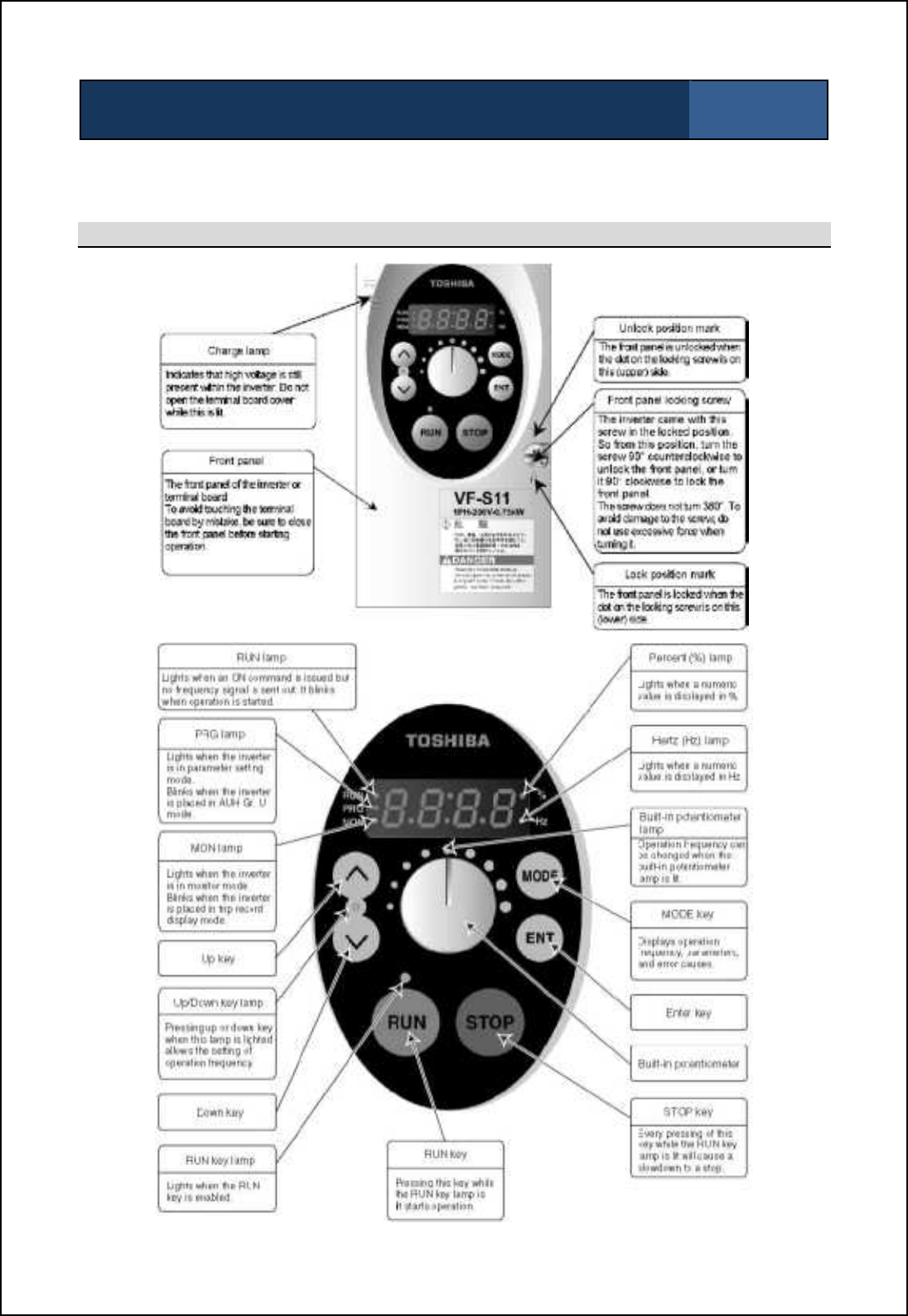
SBS-900 Shore Based Radar Systems
Chapter 9: Planned maintenance
KH-1602-2 issue 1: Standard SBS900 Systems Operator & Maintenance Handbook
Page 103 of 240
5-year maintenance: Changing the static inverter in the RDU Inspection sheet
3 of 6
When a new inverter is switched ON for the first time, it must be configured as shown below BEFORE
connecting the three-phase output to the antenna motor (PL4 on the Radar Distribution Unit).
Inverter operation overview

SBS-900 Shore Based Radar Systems
Chapter 9: Planned maintenance
KH-1602-2 issue 1: Standard SBS900 Systems Operator & Maintenance Handbook
Page 104 of 240
5-year maintenance: Changing the static inverter in the RDU Inspection sheet
4 of 6
Inverter first time POWER ON
DO NOT reconnect the three-phase connection (PL4 on the base of the RDU) to the antenna motor.
Reconnect and switch ON the single and three-phase AC power to the RDU and switch the system
ON.
At first switch-ON the inverter initialises and the readout displays n50, which indicates 50Hz input
conditions will be set. If this does not occur, press.until n50 is displayed.
Press ENTER. The inverter will set the relevant internal settings; the display will show HELLO then
settle at 0.0.
Operator controls
- Whilst programming, the Prg indicator will illuminate when the main menus are selected and Flash
when the F.--- settings menu have been selected.
- Press.to scroll down through a function menu.
- Press /to scroll up through a function menu.
- At any menu function press ENT to read the current setting then press the ./ buttons to change
the setting.
- Press ENT to accept the new setting and return to function menu.
- When the menu reaches F---, Press ENT to access F100 then .to scroll F101, F102 etc.
- At any F--- function press Ent to read the current setting then press the ./ buttons to change the
setting.
- To Exit the menus, press the MODE button until 0.0 is displayed.
Inverter configuration
When a replacement inverter is first switched on, the following parameters must be checked and set.
Firstly press the MODE button to enter programming mode then select and configure the following:
Custom Settings for TOSHIBA VF-S11 static Inverter
Function Description Set to Available modes
CN0d Command mode 00: Remote Control
1: Inverter operation panel
FN0d Frequency setting mode 5
0: Internal potentiometer setting
1: VIA
2: VIB
3: Operation panel
4: Serial communication
5: External contact up/down
6: VIA+VIB (Override)
typ Standard setting mode
(Input frequency) 1
0: -
1: 50Hz default setting
2: 60Hz default setting
3: Standard default setting (initialisation)
4: Trip record clear
5: Cumulative operation time clear
6: Initialization of type information
7: Save user-defined parameters
8: Call user-defined parameters
9: Cumulative fan operation time record clear

SBS-900 Shore Based Radar Systems
Chapter 9: Planned maintenance
KH-1602-2 issue 1: Standard SBS900 Systems Operator & Maintenance Handbook
Page 105 of 240
5-year maintenance: Changing the static inverter in the RDU Inspection sheet
5 of 6
Function Description Set to Available modes
FR Forward / reverse 0
0: Forward run
1: Reverse run
2: Forward run (F/R switching possible)
3: Reverse run (F/R switching possible)
ACC
Acceleration time
2
.0
0.0-3200
dEC
Deceleration time
10
.0
0.0-3200
FH Maximum frequency 50 30.0-500.0 (Hz) Set by TYP
UL Upper limit frequency 50 0.5 - FH (Hz) Set by TYP
LL Lower limit frequency 00.0 - UL (Hz)
uL
Base frequency (motor)
50
25-500.0 Set by TYP
uLu
Base frequency voltage 1
440
50-660 (500/600V class) As required
Pt V/F Control mode selection 0
0: V/F constant
1: Variable torque
2: Automatic torque boost control
3: Vector control
4: Energy-saving
5: Dynamic energy-saving (for fans and pumps)
6: PM motor control
ub
Torque boost
5
0.0-30.0
tHr Motor thermal protection level
34
or
80
The power limit setting depends on the gearbox in use:
Standard systems: Set to 34% (750W motor)
Advanced systems: Set to 80% (1.5KW motor)
0LN
Thermal protection level
0
Overload protection OFF, overload stall ON
Sr-1 Pre-set speed frequency 1 11 11Hz (10 RPM)
Sr-2 Pre-set speed frequency 2 22 22Hz (20 RPM)
Sr-3 Pre-set speed frequency 3 44 44Hz (40 RPM)
Sr
-
4
Pre-set speed frequency 4
0
.0
0Hz
Sr
-
5
Pre-set speed frequency 5
0
.0
0Hz
Sr
-
6
Pre
-
set
speed frequency
6
0
.0
0Hz
Sr
-
7
Pre
-
set
speed frequency
7
0
.0
0Hz
F--- Extended parameter ENT Press ENT to enter extended F--- menus.
F109 Analogue / logic input
function select 2Contact input
F111
Assigns F input (forward) for an
external stop safety command
which overrides all software &
manual control settings.
2Trip stop command from external input device disabled.
F170 Base frequency 2 50 25.0-500.0 Set by TYP
F300
PWM carrier frequency
4
.0
2.0 - 16.0
F301 Auto restart 0
0: Disabled
1: At auto-restart after momentary stop
2: ST terminal on or off
3: At auto-restart or when turning STCC on or off
4: At start-up
F302 Repetitive power ride-through 00: Disabled
1: Automatic setting
2: Slowdown stop
F303 Retry selection (set for 5
times at 1 second intervals) 50: Disabled
1-10
F417
Motor rated speed
2820 - Ybe 3.Cm rglcs fXgg\aZ
3384 - Ybe 4.Cm rglcs fXgg\aZ
2820
or
3384
100-32000
F607 Motor 150% overload time
limit 10 10 to 2400 seconds
F634 Annual average ambient temp 331 to 40°C

SBS-900 Shore Based Radar Systems
Chapter 9: Planned maintenance
KH-1602-2 issue 1: Standard SBS900 Systems Operator & Maintenance Handbook
Page 106 of 240
5-year maintenance: Changing the static inverter in the RDU Inspection sheet
6 of 6
Measuring the three phase output
The three phase output of the inverter is a pulse width modulated (PWM) sine wave which cannot be
accurately measured using a standard DVM (Digital voltmeter).
If measured the 440VAC output will actually measure approximately 220VAC +/-10% depending on
the multimeter being used.
Completion of task
On completion of the inverter commissioning, switch the system OFF and reconnect the three-phase
output to the antenna motor (PL4 on the base of the RDU).
Switch the system ON and ensure that the inverter is operational and that the antenna is rotating.
When operational, the inverter will have the following status:
'The charge light will be ON
'The Run indicator will be ON
'The display will show 22Hz for 20RPM systems and 44Hz for 40 RPM systems.
With the inverter ON and the antenna rotation and man aloft switches are in the FREE position the
antenna should rotate.
Remote control operation
When the inverter and fan replacement is completed, ensure that the Local/ Remote switch on the
Radar Distribution Unit (RDU) is in the Remote position.
Ensure that the system can be remotely controlled and is fully operation.
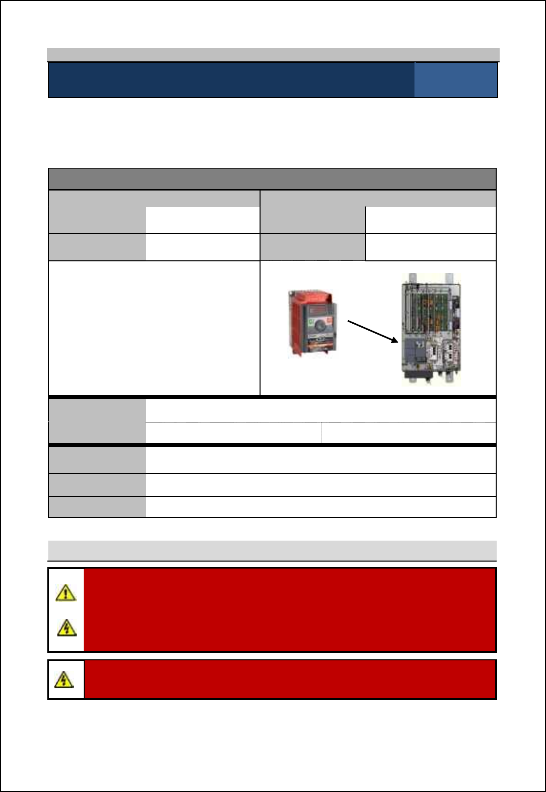
SBS-900 Shore Based Radar Systems
Chapter 9: Planned maintenance
KH-1602-2 issue 1: Standard SBS900 Systems Operator & Maintenance Handbook
Page 107 of 240
9.6.2 5-year maintenance VF-nC3
5-year maintenance: Changing the static inverter in the RDU Inspection sheet
1 of 6
After 5-years of use, the VF-nC3 static inverter located within the Radar Distribution Unit must be
changed as over time, the electrolytic capacitors within the inverter can dry out.
This maintenance procedure applies to Radar Distribution Units fitted with the inverter detailed below.
Equipment details
Radar Distribution Unit (RDU) Replacement Inverter
Part number SBS-A1- Part number 45-690-0066-001
Serial number Serial number
Toshiba VF-nC3
With the exception of the user replaceable
fan, the VF-nC3 inverter is a sealed unit that
contains no field serviceable or repairable
parts.
The unit must never be dismantled or
repaired in the field.
Toshiba VF-nC3 inverter
Radar distribution unit
Inverter
replacement date
(DD/ MM/ YYYY)
Changed by Print: Sign:
Tools required A general selection of flat and cross headed screwdrivers.
Skill level Mechanical and electrical training including awareness of single and three
phase AC supplies.
Time Less than two hours depending on equipment location and accessibility
Health and safety
WARNING: Prior to commencing any maintenance procedure, users must familiarise
themselves with the health & safety warnings noted in the planned maintenance and health
and safety sections of the system handbooks KH-1601-1 or KH-1601-2.
Prior to carrying out planned maintenance, the system must be fully isolated and
disconnected from all single and 3-phase AC supplies. See system isolation in the planned
maintenance section of the system handbook KH-1601-2.
Warning: When powered lethal voltages are present on the terminals and within the
inverter.
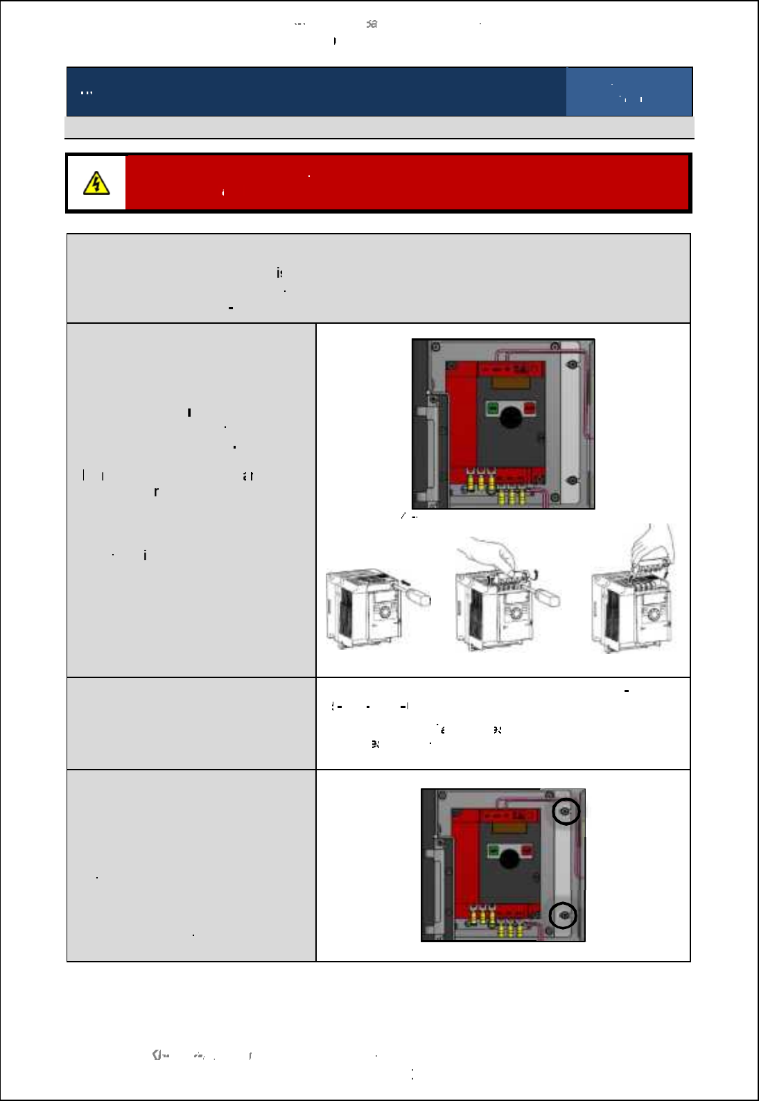
SBS
-
900 Shore
Ba
Ba
sed
Radar Systems
Chapter
9
:
Planned maintenance
KH
KH
-
1602 2
issue 1
:
Standard SBS900 Systems Operator & Maintenance Handbook
Page
108
of
240
5
-
year maintenance:
Changing the static inverter in the RDU
Inspection sheet
2
of
6
Single phase input inverter removal and replacement
Disconnect the power:
As noted in the health and safety warning, all AC sources must be
FULLY isolated
and
disconnected
form the radar distribution unit prior to commencing this task.
Disconnection:
-
Ensure the system is
fully
isolated from all sources of power including UPS supplies
-
Disconnected from all power sources from the RDU
-
Disconnect PL4 (3
-
Phase out
to antenna motor) from the base of the RDU
Disconnect the inverter
IMPORTANT:
Prior to
disconnecting
any cables,
make a
note of the
cable
positions
and
cable numbers as these are NOT
shown in this handbook
T
he
main
screw terminals
c
a
n be
accessed by
removing the covers as
shown.
Noting the cable numbers and
locations, d
isconnect all cables to the
inverter.
VF
VF
-
nC3 terminal positions (top and bottom)
Terminal cover removal
Replacement inverter
Kelvin Hughes spare part number
for Toshiba VF
-
nC3:
45
45
-
690
-
0066
001
Caution:
The use of
alternative
s
or unapproved spares
invalidate
s
the warranty status of the unit and can effect or inhibit
system performance.
Removal
and replacement
The inverter is retained into the RDU
chassis by 2 bolts as shown.
Remove and retain these bolts.
The inverter can be removed from the
RDU.
The replacement inverter can now be
installed using the same mounting
points and fasteners.
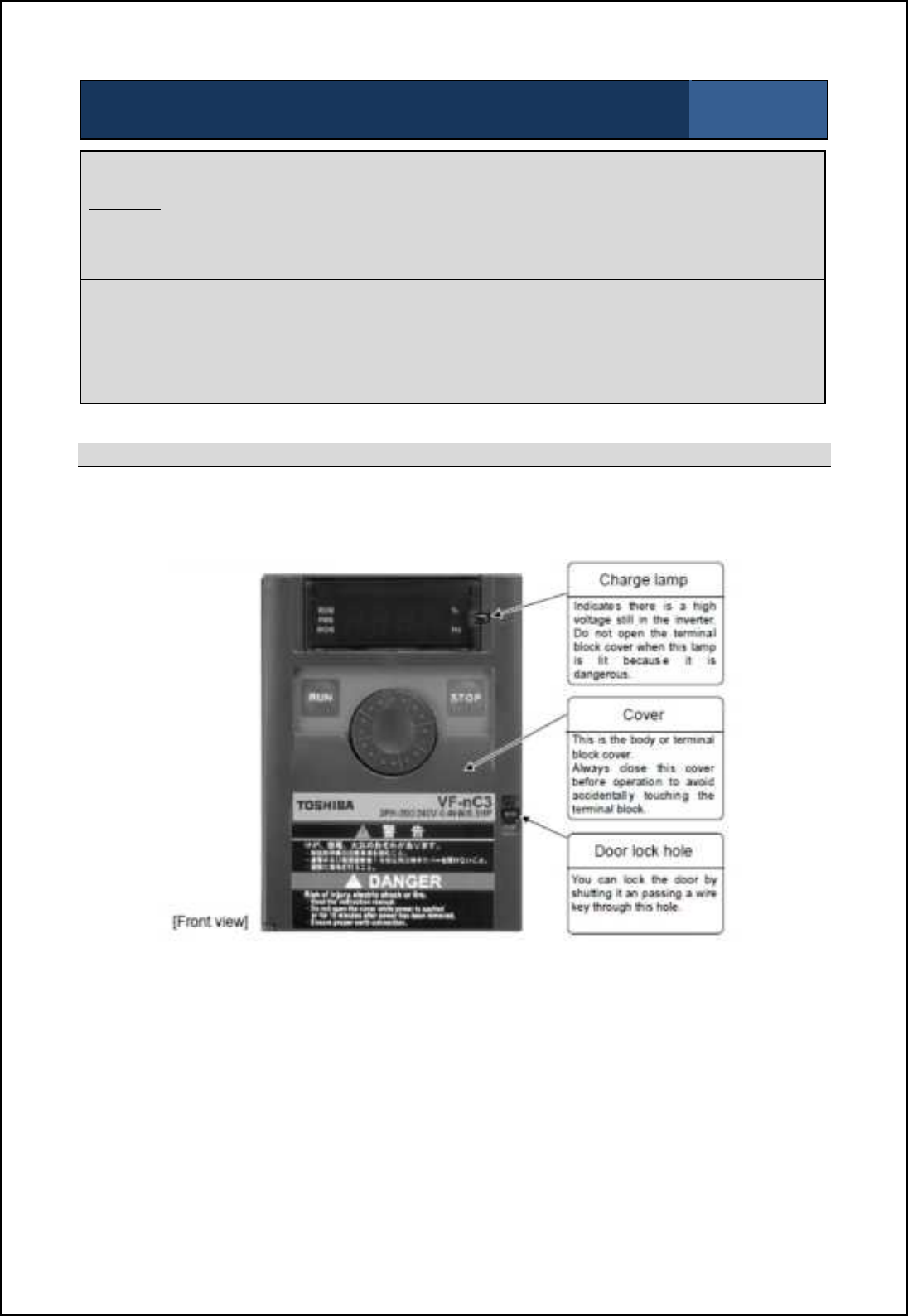
SBS-900 Shore Based Radar Systems
Chapter 9: Planned maintenance
KH-1602-2 issue 1: Standard SBS900 Systems Operator & Maintenance Handbook
Page 109 of 240
5-year maintenance: Changing the static inverter in the RDU Inspection sheet
3 of 6
Antenna motor connection
DO NOT CONNECT PL4
PL4 is the 3-Phase output to antenna motor.
The inverter must be configured BEFORE power is connected to the antenna.
Reconnect all cables to the inverter
Reconnect all other cables ensuring that they are replaced in the correct positions, polarity and/ or
marker numbers as noted when removing them earlier.
The inverter MUST now be commissioned as shown on the following pages.
Inverter control overview
After replacing the inverter and prior to applying AC power to the RDU/ inverter, engineers must
familiarise themselves with the inverter operation as shown below:
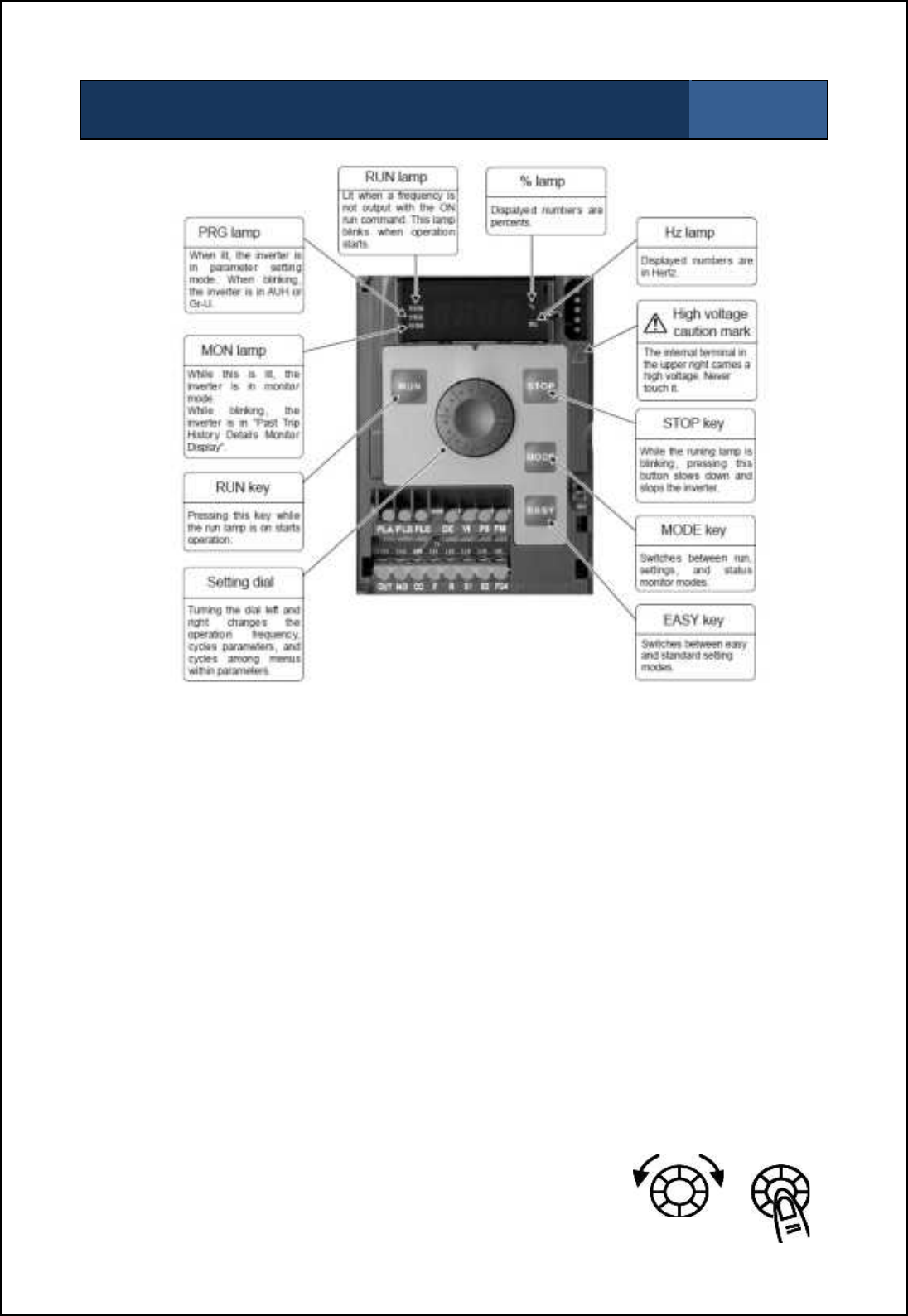
SBS-900 Shore Based Radar Systems
Chapter 9: Planned maintenance
KH-1602-2 issue 1: Standard SBS900 Systems Operator & Maintenance Handbook
Page 110 of 240
5-year maintenance: Changing the static inverter in the RDU Inspection sheet
4 of 6
A. First time POWER ON
i. With PL/ SK 4 disconnected apply power to the RDU.
ii. The inverter initialises and the display will show HELLO then settle at 0.0.
B. Region Setting
i. If the display is flashing SEt, then a region code has to be entered.
ii. Rotate the wheel to ASIA and press wheel to set, (init will appear) display should now be 0.0.
iii. If Set is not flashing it is necessary to restore the inverter back to the factory default setting prior
to entering a new region code.
iv. Ol_mm LNCD [h^ \s `iffiqcha nb_ aoc^[h]_ \_fiq m_n nsj ni 02- @`n_l l_m_n+ m_n nb_ l_acih
code to ASIA as detailed above.
C. Custom Settings
The Inverter parameters must then be changed as follows:
i. Press MODE, AUH should appear, then rotate wheel to CnOd and press wheel to set parameter
as shown in the following page. (Pressing the wheel after each setting should advance to next
function).
ii. Rotate the wheel clockwise to scroll down through the function menu as listed below. Rotating
the wheel counter clockwise will scroll up the menu.
iii. At any function press the wheel to read the function setting. Rotate
wheel to change setting.
iv. Press the wheel to enter a new setting and return to function menu.
v. To exit menus, press STOP button (4 times) until 0.0 is displayed

SBS-900 Shore Based Radar Systems
Chapter 9: Planned maintenance
KH-1602-2 issue 1: Standard SBS900 Systems Operator & Maintenance Handbook
Page 111 of 240
5-year maintenance: Changing the static inverter in the RDU Inspection sheet
5 of 6
First time switch ON inverter configuration
Custom Settings for TOSHIBA VFNC3 Inverter
Function Description Set to Operation
CN0d Command Mode 00 - GTX-A104 SKA control
1 - Inverter operation panel
FN0d Frequency Setting Mode 0
0 - GTX-A104 SKA control
1 - Inverter operation panel
2 - Inverter panel potentiometer
FnSL Meter Selection Mode 0N/A
Fn Meter gain adjustment 0N/A
Fr Forward / Reverse 00 - Forward
1 - Reverse
ACC Acceleration Time
5
5 seconds
dEC Deceleration Time
10
10 seconds
FH Maximum Frequency 50 Hahil_; m_n \s nsj
UL Upper Limit Frequency 50 Hahil_; m_n \s nsj
LL Lower Limit Frequency 00Hz
uL Base Frequency, (Motor)
50
Hahil_; m_n \s nsj
uLu Supply Voltage
230
Hahil_; m_n \s nsj
Pt V/F Control Mode Selection 0Voltage / Frequency constant
3 - Sensor less Vector control
ub Torque Boost 55% boost
tHr Motor thermal protection level
34
or
80
The power limit setting depends on the gearbox
in use:
Standard systems: Set to 34% (750W motor)
Advanced systems: Set to 80% (1.5KW motor)
0LN Electronic Thermal Protection
Level 0Overload Protection OFF
Overload Stall ON
Sr-1 Pre-set Speed Frequency 1
11
11Hz (10RPM)
Sr-2 Pre-set Speed Frequency 2
22
22Hz (20RPM)
Sr-3 Pre-set Speed Frequency 3
44
44Hz (40RPM)
Sr-4 Pre-set Speed Frequency 4 00Hz
Sr-5 Pre-set Speed Frequency 5 00Hz
Sr-6 Pre-set Speed Frequency 6 00Hz
Sr-7 Pre-set Speed Frequency 7
0
0Hz
typ Default parameters
1__0
or
2__0
1 __0, sets FH, UL, uL & F170 to 50Hz
2__0, sets FH, UL, uL & F170 to 60Hz
Note: SET 4 selects factory default settings of various
parameters including 50Hz operation suitable for Europe
region.
SEt Region 3Set at initial power or at OEM factory to Asia
PSEL Registered Parameter display
0
Hahil_; m_n \s nsj
F1-- Extended Parameter
Press
w
heel
F109 Analogue / Logic input function
select 0Voltage signal input (0 - 10 V) for V1
F127 Sink / Source input selection 0Sink
F170 Base Frequency 50 Hahil_; m_n \s nsj
F300 PWM Carrier Frequency 44kHz
F301 Auto Restart
0
Disabled
F302 Repetitive Power Ride-Through
0
Disabled
F303 Retry Selection
5
5 times at 1 second intervals
F417 Motor Rated Speed 2820
3384 2820 `il 4/Gt nsj m_nncha
3384 `il 5/Gt nsj m_nncha
F607 Motor 150% overload time limit
10
10 to 2400 seconds

SBS-900 Shore Based Radar Systems
Chapter 9: Planned maintenance
KH-1602-2 issue 1: Standard SBS900 Systems Operator & Maintenance Handbook
Page 112 of 240
5-year maintenance: Changing the static inverter in the RDU Inspection sheet
6 of 6
Measuring the three phase output
The three phase output of the inverter is a pulse width modulated (PWM) sine wave which cannot be
accurately measured using a standard DVM (Digital voltmeter).
If measured the 440VAC output will actually measure approximately 220VAC +/-10% depending on
the multimeter being used.
Completion of task
On completion of the inverter commissioning, switch the system OFF and reconnect the three-phase
output to the antenna motor (PL4 on the base of the RDU).
Switch the system ON and ensure that the inverter is operational and that the antenna is rotating.
When operational, the inverter will have the following status:
'The charge light will be ON
'The Run indicator will be ON
'The display will show 22Hz for 20RPM systems and 44Hz for 40 RPM systems.
With the inverter ON and the antenna rotation and man aloft switches are in the FREE position the
antenna should rotate.
Remote control operation
When the inverter and fan replacement is completed, ensure that the Local/ Remote switch on the
Radar Distribution Unit (RDU) is in the Remote position.
Ensure that the system can be remotely controlled and is fully operation.
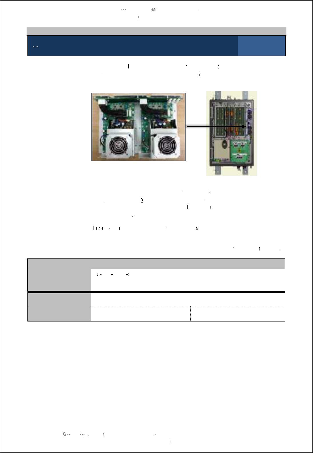
SBS
-
900 Shore
Ba
Ba
sed
Radar Systems
Chapter
9
:
Planned maintenance
KH
KH
-
1602 2
issue 1
:
Standard SBS900 Systems Operator & Maintenance Handbook
Page
113
of
240
9.6.3
Power Supply Fans
5
-
year maintenance:
Changing the
RDU PSU fans
Inspection sheet
1 of 1
PSU fans:
Regardless of t
he inverter fitted within
the system, t
he two fans mounted on
the
power supply
unit
within the RDU
have
a
manufacturers MTBF of 50K
hours.
Radar Distribution Unit Power Supply
Radar distribution unit
Fan fail:
In the event of a failure,
a
fan failure
warning is
displayed on
the RDU
front
panel
, service displa
y or command and display system. The power unit
continues to operate when a fan fails; t
he faulty
unit must be
replaced
as
soon as possible
.
Replacement:
T
he
he
se
se
fans
must be
changed
every
5 year
s as part of a
routine maintenance
schedule.
Procedure:
The procedure for replacing the fan is detailed in section
10.8.7.4
p
age
193
.
Fan replacement
Fan replacement part
number:
45
45
-
690
-
0080
003
(Order x2 for replacement)
Note: The replacement part is the fan only and does not contain the casework which must be
removed from the
old
fan.
Fan replacement date
(DD/ MM/ YYYY)
Changed by:
Print:
Sign:
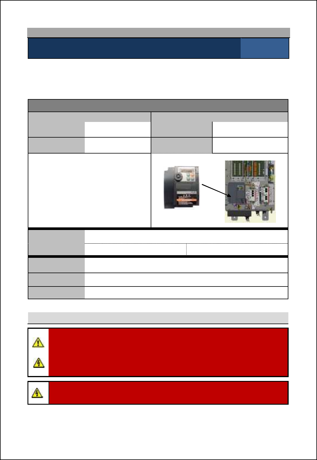
SBS-900 Shore Based Radar Systems
Chapter 9: Planned maintenance
KH-1602-2 issue 1: Standard SBS900 Systems Operator & Maintenance Handbook
Page 114 of 240
9.7 10-year maintenance: VF-S15
10-year maintenance: Changing the static inverter in the RDU Inspection sheet
1 of 6
After 5-years of use, the VF-nC3 static inverter located within the Radar Distribution Unit must be
changed as over time, the electrolytic capacitors within the inverter can dry out.
This maintenance procedure applies to Radar Distribution Units fitted with the inverter detailed below.
Equipment details
Radar Distribution Unit (RDU) Replacement Inverter
Part number SBS-A1- Part number 45-690-0084-002
Serial number Serial number
Toshiba VF-S15
With the exception of the user replaceable
fan, the inverter is a sealed unit that contains
no field serviceable or repairable parts.
The unit must never be dismantled or
repaired in the field. VF-S15 inverter
R
adar distribution unit
Inverter
replacement date (DD/ MM/ YYYY)
Changed by Print: Sign:
Tools required A general selection of flat and cross headed screwdrivers.
Skill level Mechanical and electrical training including awareness of single and three
phase AC supplies.
Time Less than two hours depending on equipment location and accessibility
Health and safety
WARNING: Prior to commencing any maintenance procedure, users must familiarise
themselves with the health & safety warnings noted in the planned maintenance and health
and safety sections of the system handbooks KH-1601-1 or KH-1601-2.
Prior to carrying out planned maintenance, the system must be fully isolated and
disconnected from all single and 3-phase AC supplies. See system isolation in the planned
maintenance section of the system handbook KH-1601-2.
Warning: When powered lethal voltages are present on the terminals and within the
inverter.
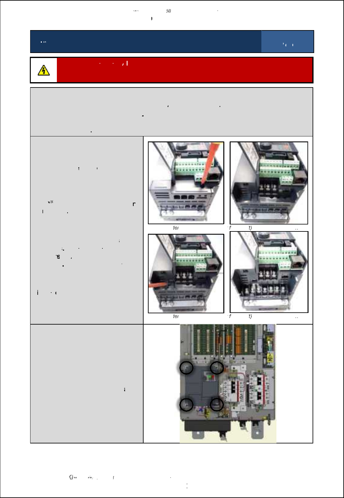
SBS
-
900 Shore
Ba
Ba
sed
Radar Systems
Chapter
9
:
Planned maintenance
KH
KH
-
1602 2
issue 1
:
Standard SBS900 Systems Operator & Maintenance Handbook
Page
115
of
240
10
10
-
year maintenance:
Changing the static inverter in the RDU
Inspection sheet
2
of
6
Disconnect the power:
A
ll AC sources
including UPS supported supplies
must be FULLY isolated
and disconnected
from
the Radar Distribution Unit prior to commencing this
or any maintenance
task.
Disconnection:
Ensure
the system is fully disconnected from all
AC
power sources
Disconnect/ unplug PL4
: This is the 3
-
phase supply to the antenna motor and is located on the
base of the Radar Distribution Unit.
This must not
be reconnected until the replacement inverter
has been configured
The main screw terminals protected
by a removable
safety
cover.
This is
removed by gently pushing a small
screwdriver into the locking tab as
shown.
The 2
nd
nd
nd
lower protective tab can the
n
be
removed
IMPORTANT: Prior to
disconnecting any cables make
a full note of the positions
/ pin
numbers
, polarity and cable
marker
s
of
ALL
cables
being
removed
The cable pin outs are
The cable pin outs are
not shown
in this document.
Having noted the cable locations,
d
isconn
ect all cables from the
inverter.
Upper t
erminal protection cover
fitted (left
) and removed (right)
Lower t
erminal protection cover
fitted (left
) and removed (right)
Removal
and replacement
The inverter mounted onto a plate
that is held in the RDU chassis by 4
bolts.
Removed and retain these bolts
as
they are required for refitting.
The inverter can now be removed
from the RDU.
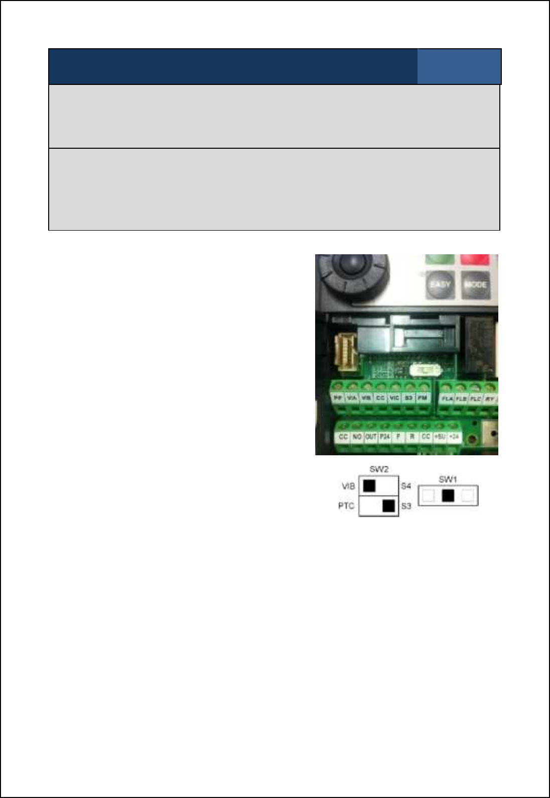
SBS-900 Shore Based Radar Systems
Chapter 9: Planned maintenance
KH-1602-2 issue 1: Standard SBS900 Systems Operator & Maintenance Handbook
Page 116 of 240
10-year maintenance: Changing the static inverter in the RDU Inspection sheet
3 of 6
The inverter is mounted onto a flat plate; this must be removed and fitted to the replacement
inverter.
The replacement inverter assembly can now be installed using the same mounting points and
fasteners.
Reconnect
DO NOT reconnect PL4 (3-phase supply to antenna motor).
Reconnect all other cables ensuring that they are replaced using the positions, polarity and/ or
marker numbers noted when removing them earlier.
The inverter will now need to be commissioned as shown below.
A.
Switch
Settings: There are two switches within
the inverter that need to be
configured as follows.
The switches are located
behind the access door on the
front of the unit.
These switches MUST be set
before power is applied to a
replacement inverter and
before any changes are made
to the inverter setup menus.
SW1: Set to the middle
position.
SW2 Set as shown.
B. First time POWER ON
Switch ON the AC mains supply connected to PL3. The inverter will initialise and the readout
should display n50. This indicates 50Hz input conditions will be set (if not, press.button
until n50 is displayed).
Press ENTER. The inverter will set the relevant internal settings; the display will show
HELLO then settle at 0.0.

SBS-900 Shore Based Radar Systems
Chapter 9: Planned maintenance
KH-1602-2 issue 1: Standard SBS900 Systems Operator & Maintenance Handbook
Page 117 of 240
10-year maintenance: Changing the static inverter in the RDU Inspection sheet
4 of 6
C. Custom Settings
The Inverter parameters must then be changed as follows:
Press the MODE button.
'Whilst programming, the Prog indicator is ON for main function path and Flashing
for F.---setting path.
'Press.buttons to scroll down through the function menu as listed below. Pressing
/button scrolls up the menu.
'At any function press ENT to read the function setting. Press ./ buttons to change
setting.
'Press ENT to enter new setting and return to function menu.
'When the menu reaches F---, Press ENT to access F100 then .to scroll F101
F102 to F990.
'Pressing /scrolls F100, F990, F880 .. to F100.
'At any F--- function press Ent to read function setting and ./buttons to change
Setting.
'Press Ent to enter the new setting and return to the Function menu.
'To exit menus, press MODE button until 0.0 is displayed.
Custom Settings for TOSHIBA Inverter
FUNCTION DESCRIPTION SET OPERATION
CN0d Command Mode 0 0 pRemote Control
1 - Inverter operation panel
FN0d Frequency Setting Mode 5
0: Internal potentiometer setting
1: VIA
2: VIB
3: Operation panel
4: Serial communication
5: External contact up/down
6: VIA+VIB (Override)
typ Standard Setting Mode
(Input frequency)
1
0: -
1: 50Hz default setting
2: 60Hz default setting
3: Standard default setting
(Initialization)
4: Trip record clear
5: Cumulative operation time clear
6: Initialization of type information
7: Save user-defined parameters
8: Call user-defined parameters
9: Cumulative fan operation time
record clear

SBS-900 Shore Based Radar Systems
Chapter 9: Planned maintenance
KH-1602-2 issue 1: Standard SBS900 Systems Operator & Maintenance Handbook
Page 118 of 240
10-year maintenance: Changing the static inverter in the RDU Inspection sheet
5 of 6
FR Forward / Reverse 0
0: Forward run
1:Reverse run
2: Forward run (F/R switching
possible)
3: Reverse run (F/R switching
possible)
ACC Acceleration Time
2.0
0.0-3200
dEC Deceleration Time 10.0 0.0-3200
FH Maximum Frequency 50.0 30.0-500.0 (Hz) Set by TYP
UL Upper Limit Frequency 50.0 0.5 - FH (Hz) Set by TYP
LL Lower Limit Frequency
0.0
0.0 - UL (Hz)
uL Base Frequency, (Motor)
50.0
25-500.0 Set by TYP
uLu Base frequency voltage 1
440
50
-
660 (500/600V class)
As required
Pt V/F Control Mode Selection 0
0: V/F constant
1: Variable torque
2: Automatic torque boost control
3: Vector control
4: Energy-saving
5: Dynamic energy-saving
(for fans and pumps)
6: PM motor control
ub Torque Boost
5.0
0.0-30.0
tHr Motor Thermal Protection
Level
34
or
80
The power limit setting depends on the
gearbox in use:
Standard systems: Set to 34% (750W
motor)
Advanced systems: Set to 80% (1.5KW
motor)
0LN Electronic Thermal Protection
Level 0Overload Protection OFF
Overload Stall ON
Sr-1 pre-set Speed Frequency 1 11.0 11Hz (10 RPM)
Sr-2 pre-set Speed Frequency 2
22.0
22Hz (20 RPM)
Sr-3 pre-set Speed Frequency 3
44.0
44Hz (40 RPM)
Sr-4 pre-set Speed Frequency 4
0.0
0Hz
Sr-5 pre-set Speed Frequency 5
0.0
0Hz
Sr-6 pre-set Speed Frequency 6 0.0 0Hz
Sr-7 pre-set Speed Frequency 7 0.0 0Hz
F--- Extended Parameter ENT
F109 Analogue / Logic input function
select 2Contact Input
F111
Assigns F input (Forward) for
an External Stop safety
command which overrides all
software and manual control
settings.
2Trip stop command from external input
device disabled.
F170 Base Frequency 2 50.0 25.0-500.0 Set by TYP
F300 PWM Carrier Frequency 4.0 2.0 - 16.0
F301 Auto Restart 0
0: Disabled
1: At auto-restart after momentary
stop
2: ST terminal on or off
3: At auto-restart or when turning STCC
on or off
4: At start-up

SBS-900 Shore Based Radar Systems
Chapter 9: Planned maintenance
KH-1602-2 issue 1: Standard SBS900 Systems Operator & Maintenance Handbook
Page 119 of 240
10-year maintenance: Changing the static inverter in the RDU Inspection sheet
6 of 6
F302 Repetitive Power Ride-
Through 0
0: Disabled
1: Automatic setting
2: Slowdown stop
F303
Retry Selection
(set for 5 times at 1 second
intervals)
50: Disabled
1-10
F417 Motor Rated Speed
2820
3384
2820
`il 4/Gt nsj m_nncha
3384 `il 5/Gt nsj m_nncha
F607 Motor 150% overload time limit 10 10 ~2400 seconds
F634 Annual Average Ambient
Temperature 321 to 30°C
Measuring the three phase output
The three phase output of the inverter is a pulse width modulated (PWM) sine wave which cannot be
accurately measured using a standard DVM (Digital voltmeter).
If measured the 440VAC output will actually measure approximately 220VAC +/-10% depending on
the multimeter being used.
Completion of task
On completion of the inverter commissioning, switch the system OFF and reconnect the three-phase
output to the antenna motor (PL4 on the base of the RDU).
Switch the system ON and ensure that the inverter is operational and that the antenna is rotating.
When operational, the inverter will have the following status:
'The charge light will be ON
'The Run indicator will be ON
'The display will show 22Hz for 20RPM systems and 44Hz for 40 RPM systems.
With the inverter ON and the antenna rotation and man aloft switches are in the FREE position the
antenna should rotate.
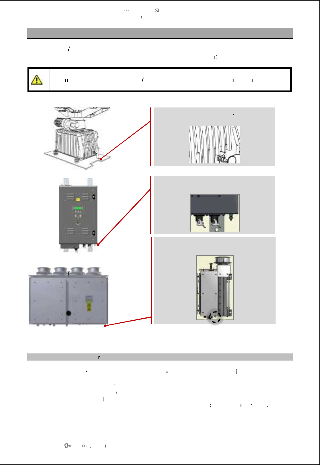
SBS
-
900 Shore
Ba
Ba
sed
Radar Systems
Chapter
9
:
Planned maintenance
KH
KH
-
1602 2
issue 1
:
Standard SBS900 Systems Operator & Maintenance Handbook
Page
120
of
240
9.8
Earth bonding maintenance
Where an earth
/ chassis
bonding point has been found to be corroded or fails a conductivity test, the
bonding joint should be dismantled, cleaned and reassembled as follows
:
Caution:
Isolate the system before commencing this task.
Under no circumstances should straps or
equip
ment be disconnected from earth
/ chassis
before all power supplies are
isolated
removed at
source.
Earth bonding cleaning p
rocedure
(
Fully i
solate the equipment
from the single and 3
-
phase AC power
supplies
including any UPS
supported supplies
(
Release the nuts/bolts securing the equipment/
straps.
(
Clean the affected parts with
a
wire brush or emery cloth to provide bright metal surfaces.
(
Refit the equipment/stra
ps and tighten all nuts/bolts.
(
Carry out a continuity check in accordance with
the appropriate m
aintenance
procedure
(
If the test is satisfactory, restore the equipment power supplies and test the system.
Radar Distribution Unit
(all variants)
M6 grounding/ earth stud
Gearbox
(all variants)
Grounding strap
Transceiver enclosure
(all variants)
M6 grounding/ earth stud
SBS-900 Shore Based Radar Systems
Chapter 10: Corrective maintenance
KH-1602-2 issue 1: Standard SBS900 Systems Operator & Maintenance Handbook
Page 121 of 240
10 Corrective maintenance
The following section details the corrective maintenance tasks that can be carried out on all standard
SBS-900 systems
Health & Safety notices: When carrying out any corrective or planned maintenance, the health
and safety notices shown in section 2 must be observed at all times.
Fibre optic cables: Where fibre optic cables are removed as part of any maintenance
procedure the protective dust caps must be fitted to prevent damage
to the fibre optic terminals or dust ingress within the connector.
10.1 General precautions
Antenna Rotation Safety Notice:
When three-phase power is connected to the system and switched ON, the antenna may
rotate immediately regardless of the RUN command status.
Use the antenna rotation keyswitch, man aloft safety switches or antenna control in the
command and display system to stop antenna rotation in an emergency.
WARNING: Prior to commencing any maintenance procedure, users must familiarise
themselves with the health & safety warnings noted in the planned maintenance and health
and safety sections of the system handbooks.
AC supplies: Prior to carrying out any maintenance, the system must be fully isolated and
disconnected from all single and 3-phase AC supplies. This must include the full isolation
of any UPS supported supplies to the equipment.
Caution: The motor/ gearbox assembly must NEVER be dismantled as this would cause
significant loss of oil and damage to oil seals.
Caution: When the gearbox and antenna have been operating in strong sunlight or
elevated temperatures, the gearbox casing and antenna surfaces will be extremely hot.

SBS-900 Shore Based Radar Systems
Chapter 10: Corrective maintenance
KH-1602-2 issue 1: Standard SBS900 Systems Operator & Maintenance Handbook
Page 122 of 240
10.2 Standard systems overview
10.2.1 Power connections
AC/ DC
power: RDU: Two sources of UPS supported single phase AC and a separate
three phase supply are connected to the RDU.
Internal breakers and contactors control the AC voltages to the rest
of the system.
An internal power supply generates all the DC rails required by the
RDU.
Transceiver
Enclosure Single or dual (system dependent) sources of AC power are
connected from the RDU and are internally protected and switched
by the use of breakers.
Internal power supplies generate all the DC rails required by the
transceiver enclosure.
A separate DC rail is provided to power the ACP/ ARP encoder in the
antenna sub-system.
Antenna sub-
system The antenna motor is driven by the three phase output of the RDU
(see below).
A DC rail from the transceiver Enclosure is used to power the ACP/
ARP encoder.
Three phase measurement: The three phase output of the inverter is a pulse width modulated
(PWM) sine wave which cannot be accurately measured using a
standard DVM (Digital voltmeter).
If measured the 440VAC output will actually measure approximately
220VAC +/-10% depending on the multimeter being used.
10.2.2 Over current protection devices
Kelvin Hughes gearboxes: There are no fuses or breakers located within the gearbox for the AC
supplies to the Kelvin Hughes gearbox.
The safety mechanisms within the Radar Distribution unit and
transceivers which include the Man Aloft Switch and Antenna
Rotation keyswitch should be used to isolate the system.
See section 9.3 page 87 onwards for full details.
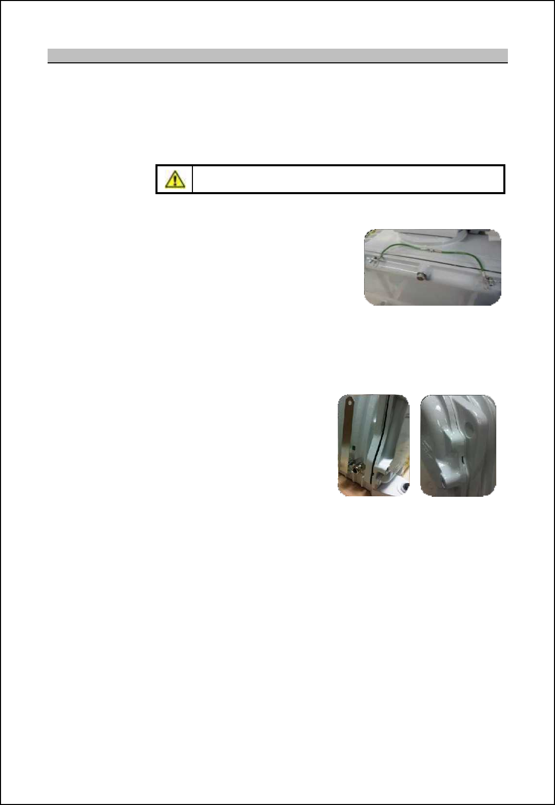
SBS-900 Shore Based Radar Systems
Chapter 10: Corrective maintenance
KH-1602-2 issue 1: Standard SBS900 Systems Operator & Maintenance Handbook
Page 123 of 240
10.2.3 Service door removal
Service Door removal: The service door on the turning mechanism must be opened to gain access
to the electrical terminations for the ACP and ARP signals and for connecting
the flexwell in S-Band systems (X-band systems connect externally).
Opening the service access door is not required for any other reason.
Caution: The service access door is heavy, care should be
exercised when removing and handling the door.
The door removal process is identical for both X and S-band systems
Safety clips: There are two safety P-clips that must be
removed to detach the door.
These clips MUST be re-attached when
replacing the service door.
Safety lanyard:
Door bolts:
To prevent a drop hazard, the door is fitted with an internally mounted safety
lanyard. If required this lanyard can be unclipped and the door carefully
lowered to a safe position.
There are nine M8/ 13mm bolts restraining the door. Care should be taken
when removing these bolts are they are NOT captive.
Release points: The door is mounted on two locating
lugs. It may be necessary to gently
leaver the door open using the two
door release points marked on the
door.
Care should be taken to ensure the
paint is not damaged whilst removing
the door.
Replacement: Prior to replacing the door, the following should be checked:
- The system is fully isolated from all sources of AC power
- Ensure the door is correctly located on the mounting lugs and that the
restrain clips have been replaced.
- Pay attention to the safety lanyard as this can easily become trapped in
the door when being closed.
- Tighten all bolts on the main door, the 3-phase motor cover and cable
glands ensuring a full waterproof seal is achieved.
- To prevent corrosion, any chipped or damaged surfaces must be painted
with polyurethane paint.

SBS-900 Shore Based Radar Systems
Chapter 10: Corrective maintenance
KH-1602-2 issue 1: Standard SBS900 Systems Operator & Maintenance Handbook
Page 124 of 240
10.2.4 Antenna removal
The Low Profile Antenna will need to be removed and temporarily stored for some maintenance tasks.
The lifting procedures are listed below.
Where an antenna is to lifted, all safety and lifting requirements noted in below must be read,
understood and fully observed.
WARNING:Antennas are heavy items and must be lifted using suitable lifting
equipment, a secured block and tackle or by rope strops.
CAUTION: During removal and installation, the antenna must be secured and supported
at all times to prevent any risk of falling or slipping.
Antennas must never be left unsupported on the swing casting.
'All health and safety requirements must be checked and observed at all times when lifting any
equipment. All appropriate personal protective equipment (PPE) must be worn.
'Where special equipment such as cranes hoists and jigs is required, consideration must be given
to the authority to use such equipment.
'During lifting, a safety zone shall be established beneath the lifting area around any cranes or
platforms. Safety personnel must ensure that persons do not encroach on the area of work.
'Consult with the lifting operator to obtain the best and safest method of securing lifting strops or
ropes to the equipment and advise lifting operators of the areas of a system that are susceptible to
^[g[a_ mo]b [m [hn_hh[ `[m]c[m+ mqcha ][mncham _n]-
'Check that the centre of gravity of the equipment cannot cause the lifting strops or ropes to slip or
move.
'All straps, lifting cables or ropes must be thoroughly checked to ensure that there is no risk of the
unit slipping or falling from the lifting strap or lifting equipment.
'If lifting a transmitter/ gearbox with the antenna pre-assembled, the lifting equipment, ropes or
straps must not place any pressure on any part of the antenna or the swing casting.
'Kelvin Hughes cannot be held responsible for any damage that occurs to supplied or 3rd party
equipment as a result of incorrect lifting procedures or handling or equipment.
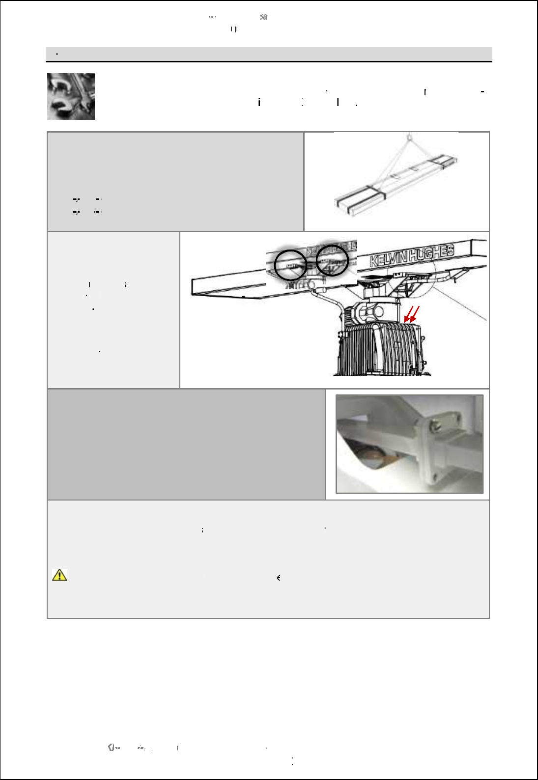
SBS
-
900 Shore
Ba
Ba
sed
Radar Systems
Chapter
10
10
:
Corrective maintenance
KH
KH
-
1602 2
issue 1
:
Standard SBS900 Systems Operator & Maintenance Handbook
Page
125
of
240
X
-
band
Antenna
removal
In addition to the normal tools required for
installation and
service work, a
n
8.0mm hex
key will be required to
remove and
install the
X
-
band
LPA
Support the antenna
Ensure the antenna is fully supported ready to be lifted.
Antenna weight:
LPA
A37
-
xxxx 3.7m low profile antenna: 20Kg
LPA
A55
-
xxxx 5.5m low profile antenna: 30Kg
S band antenna shown for illustration
purposes
Release forward bolts
On both arms of the swing
casting,
remove
and retain
the 4 bolts
and washers
indicated
.
Retain these bolts and
washers as they will be
washers as they will be
required when reinstalling
the antenna.
S band antenna shown for illustration
purposes
Disconnect the 4 x 4BA bolts that connect the antenna
waveguide to the rotating joint.
waveguide to the rotating joint.
5 CK MTC?LBPCR?GLRFCe2 fPGLEDPMK RFCAMLLCARGML?QRFGQ
will be required for refitting.
will be required for refitting.
Loosen final bolts and
remove antenna
Observing all safety requirements
and
ensuring the
antenna is
fully
supported and ready for lifting,
remove and retain the bolts and washers that hold the antenna onto the swing casting.
Retain these bolts and washers as they are required
for reinstallation of the antenna.
The antenna is now loose
and is ready to b
e
lifted.
The antenna should be carefully stored ensuring that the waveguide is not crushed, bent or
damaged. The antenna must never be handled by the waveguide.
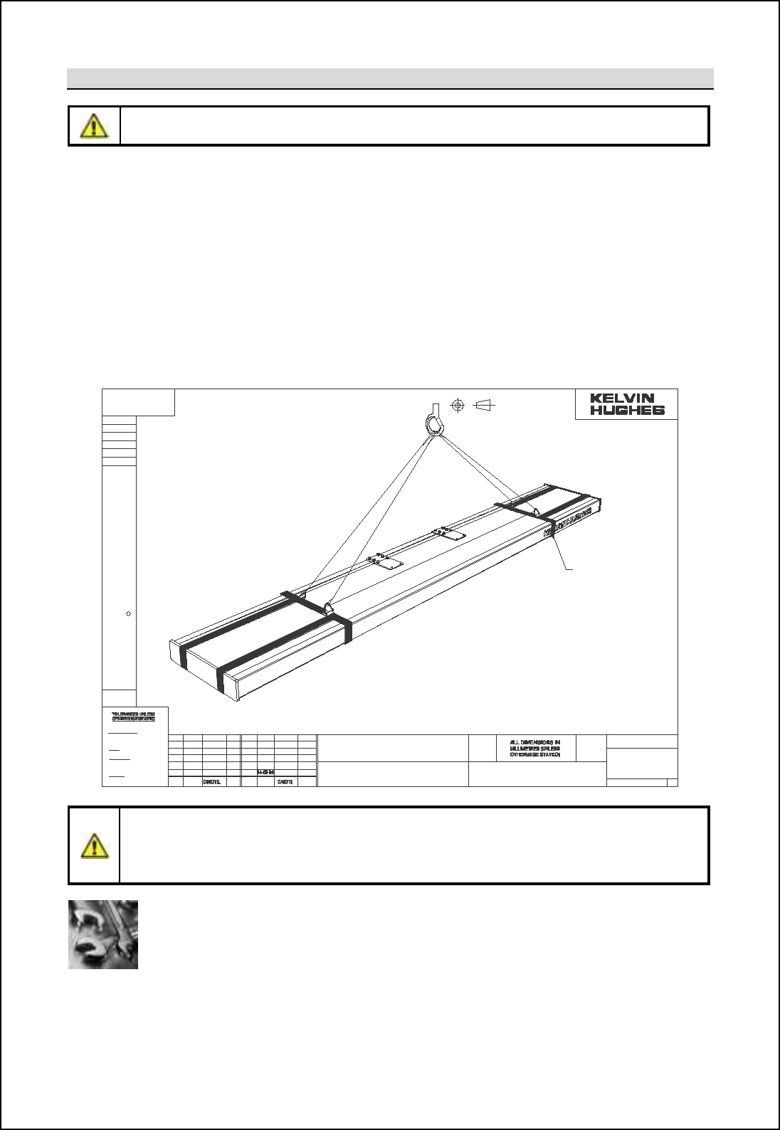
SBS-900 Shore Based Radar Systems
Chapter 10: Corrective maintenance
KH-1602-2 issue 1: Standard SBS900 Systems Operator & Maintenance Handbook
Page 126 of 240
S-band Antenna removal
Caution: All safety precautions regarding the lifting and handling of antennas noted in this section
must be read, fully understood and observed.
The Kelvin Hughes LPA-A3 and LPA-A3-BAAA S-band low profile antennas are supplied with a set of
lifting straps which must be used for lifting the antenna. These straps are individually marked with the
[hn_hh[m m_lc[f hog\_l [h^ gomn \_ retained with the equipment for possible future maintenance
work.
Prior to use, the straps must be fully checked for any signs cuts, abrasions and signs of chemical
damage. If there is any evidence of damage the lifting straps must not be used and should be
replaced.
Replacement lifting strap can be order from kelvin Hughes by quoting part number LPA-1052 (two
required) and the serial number of the antenna.
Caution: Lifting straps maximum weight
The lifting straps supplied with S-band low profile antennas have a maximum weight limit of 200Kg.
They must only be used for lifting the LPAqA3 or LPA-A3-BAAA antennas and are not designed for
lifting of any other equipment.
Tools: In addition to the normal tools required for installation and service work the
following tools will be required to remove and re-install the S-band LPA onto the
transceiver/ gearbox.
1.5mm and 8.0mm hex/ Allen key
10mm socket set (recommended)
±1 °
CL AS S H1 3
CL AS S 6 g
C LAS S 6 H
BS 36 43
SMITHS INDUSTRIES PUBLIC LI MITED COMPANY. IT ISTO BE TREATED AS CONFIDE NTIAL
C KELVIN HUGHESLIMITED
THE PREVI OUS CONS ENT OF KELVIN HUGH ESLTD.TO WHOM IT MUST B ERETURNE D
ANDMA YNOT BEREPRODUCED ORUSED ORDISCLOSEDTO THI RD PARTIESWI THOUT
THIS DOCUMENT IS THE PROPERTY OF K ELV IN HUGHES LTD. A SUBSIDIARY OF
ANG UL AR
NO DECIM A L P L AC E ± 1.0
ONE DECIMA L P L ACE ± 0.5
TW OD ECIM AL P LAC E S ±0.15
DIM ENS IO NA L
TO BS 4 50 0
HOL ES
EX TE R NAL
INTERNA L
COAR S E PITCH
SCREW TH READ S
DRAWING PRACT ICE TO BS 308
PROJECTION
THIRD ANGLE
SIG.DATEISSISS D ATE
USED ON
DRAWN
CODE No
FINISH
MATERIAL
TITLE
M/C SCALE
CODE No.
SIMILAR TO
ISS SIG.
NRDDR04581
NRD
2004
LPA-1097
NTS
LPA RECOMMENDED
LIFTING TECHNIQUE
LPA-1097
SHEET 1 OF 1 A3
DO NOT SCALE
NOTES
1.ANTENNA WEIGHT = 70 Kg
2.ENSURE LIFTING STRAPS CAN NOT FREE
RUN THRO' LIFTING HOOK.
3.ENSURE THAT LIFTING STRAP CAN NOT
RUN FREE THRO' LIFTING STRAPS LPA-1052
SEE NOTE 2
LPA-1052
SEE NOTE 3
IN 2 POS'NS
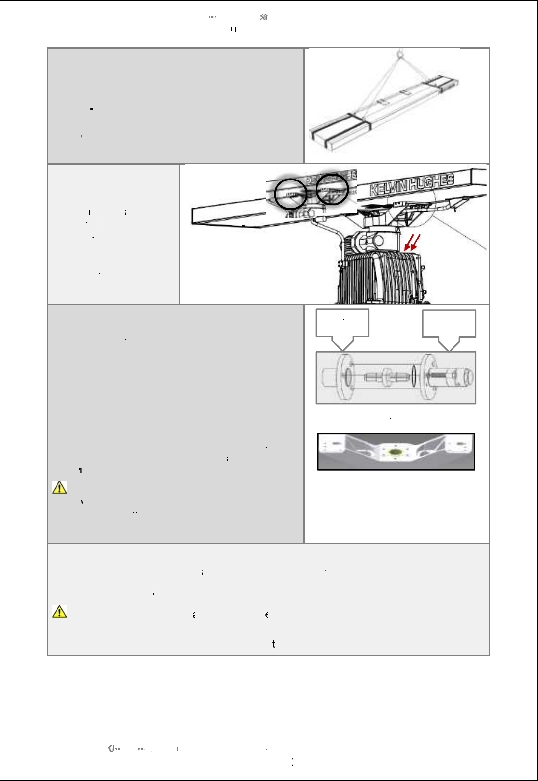
SBS
-
900 Shore
Ba
Ba
sed
Radar Systems
Chapter
10
10
:
Corrective maintenance
KH
KH
-
1602 2
issue 1
:
Standard SBS900 Systems Operator & Maintenance Handbook
Page
127
of
240
Support the antenna
Ensure the antenna is fully supported ready to be lifted.
The LPA
-
1052 lifting supports
originally
supplied with
the antenna MUST BE USED.
A
rray
weight: 70Kg
Release forward bolts
On both arms of the swing
casting,
remove
and retain
the 4 bolts
and
washers
indicated
.
Retain these bolts and
washers as they are
washers as they are
required when reinstalling
the antenna.
Release waveguide coupling
Remove the three bolts that hold the waveguide
coupling together.
Separate the waveguide and remove the coupling bullet
?LBe2 fPGLE
$LCU@SJJCR?LBe2 fPGLE?PCQSNNJGCB?QN?PRMDRFC
installation
kit.
When removing the bolts that retain the array to the
QUGLEA?QRGLERUM@MJRQFMJCQ?PCeQJMRRCBf?JJMUGLERFC
array to be moved. This can
be of
assist
ance when
remov
ing
the RF bullet in the waveguide coupling.
CAUTION: The array
must be supported
at all
times
when removing any bolts and especially if the two
when removing any bolts and especially if the two
slotted guides are the only fasteners retaining the array
to the swing casting.
Waveguide coupling showing
9 LCC<K8 E;V- WI@E>
Example of swing casting
Loosen final bolts and remove antenna
Observing all safety requirements
and
ensuring the
antenna is
fully
supported and is ready for
lifting, remove and retain the 10 bolts and washers that hold the antenna onto the swing casting.
Retain these bolts and
washers as they are required for reinstallation of the antenna.
The antenna is now loose
and is ready to b
e
lifted.
The antenna should be carefully stored ensuring that the waveguide is not crushed, bent or
damaged. The antenna must never be handled by
the waveguide.
Rotating
Joint
Flexwell to
antenna
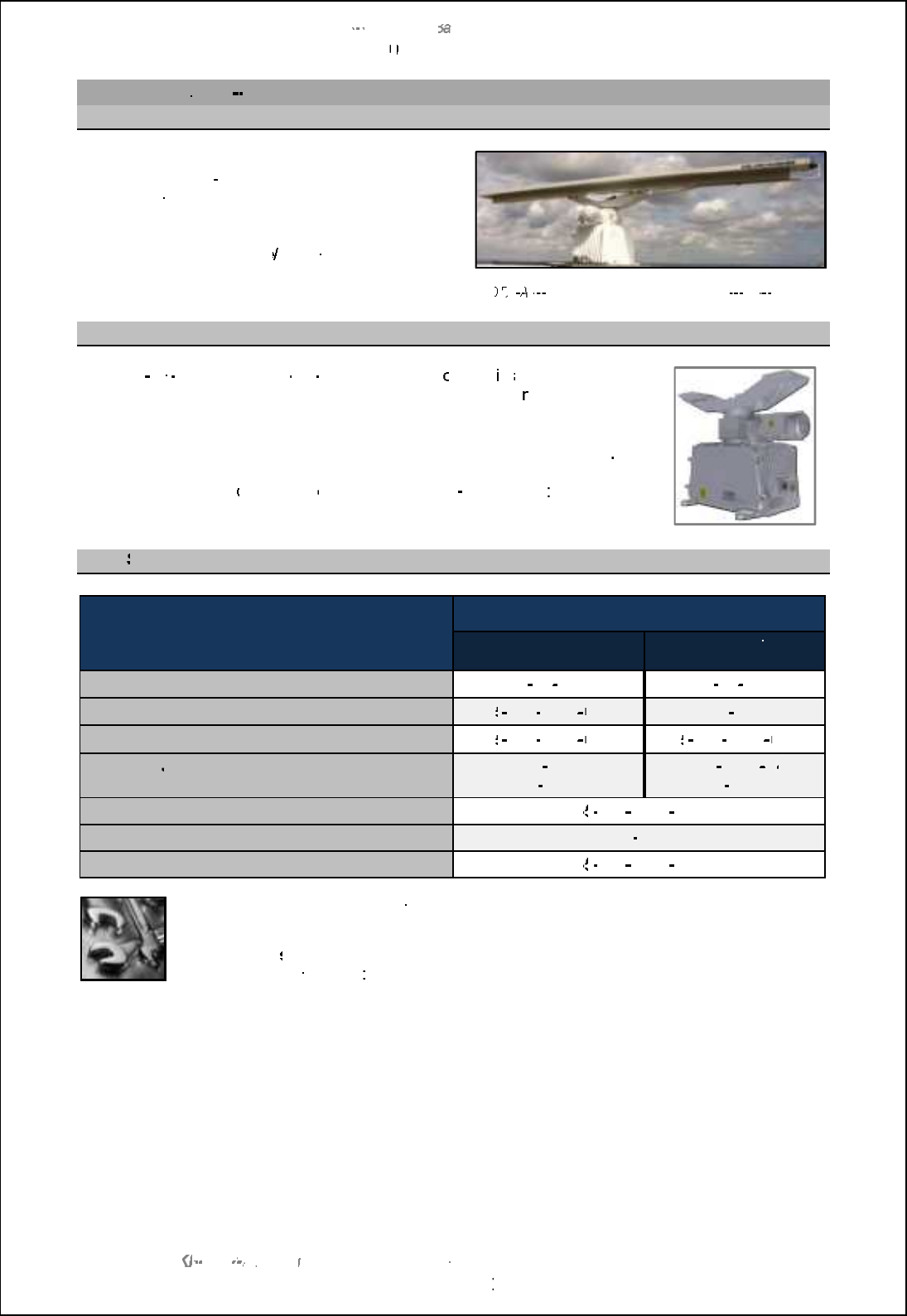
SBS
-
900 Shore
Ba
Ba
sed
Radar Systems
Chapter
10
10
:
Corrective maintenance
KH
KH
-
1602 2
issue 1
:
Standard SBS900 Systems Operator & Maintenance Handbook
Page
128
of
240
10.3
Standard X
band
10.3.1
Antenna
The corrective maintenance
for the standard
LPA
-
A37 and LPA
-
A55
Low Profile Antennas is
restricted to keeping them clean and inspecting
for damage.
See
Planned Maintenance
Annual Maintenance
for cleaning and inspection details.
Standard
D
TX
TX
A3
A3
-
AXZX gearbox fitted with an LPA
-
A55 AAAA
10.3.2
Gearbox
The
DTX
-
A3
A3
-
AXZX and DTX
-
A3
A3
-
BXZX gearbox h
ousing
is
a cast enclosure
with
a
service
cover
that allows access to the
azimuth/ headi
ng line (ACP/
ARP) encoder and it connections.
There are no other electronic assemblies within the gearbox casing
.
The
X Band gearbox
comprises
of
the following
sub
-
assemblies
10.3.3
Spares listing
X Band
system description
Part number
Casing colour
Signal white
Casing colour
Silver Grey
Complete assembly
DTX
-
A3
A3
-
AXZX
DTX
-
A3
A3
-
BXZX
Antenna motor / gearbox assembly
55
55
-
100
-
0273
001
DTX
-
A186
Motor coupling gasket
55
55
-
100
-
0273
003
55
55
-
100
-
0273
003
RF rotary
Joint
Rotating joint gasket
DTX
-
A183
GTX
-
A1246
DTX
-
A183
64
64
GTX
-
A1246
Service access door seal
55
55
-
100
-
0311
001
Azimuth/ heading line quadrature encoder
GTX
-
A188
Door seal
55
55
-
100
-
0311
001
Tools:
In addition to the normal tools required for service and
maintenance work, the
following tools will be required:
M8/ 13mm
spanner:
Used for the removal of the transceiver service door.
1.5mm hex/ Allen key
: Grub screws retaining azimuth encoder.
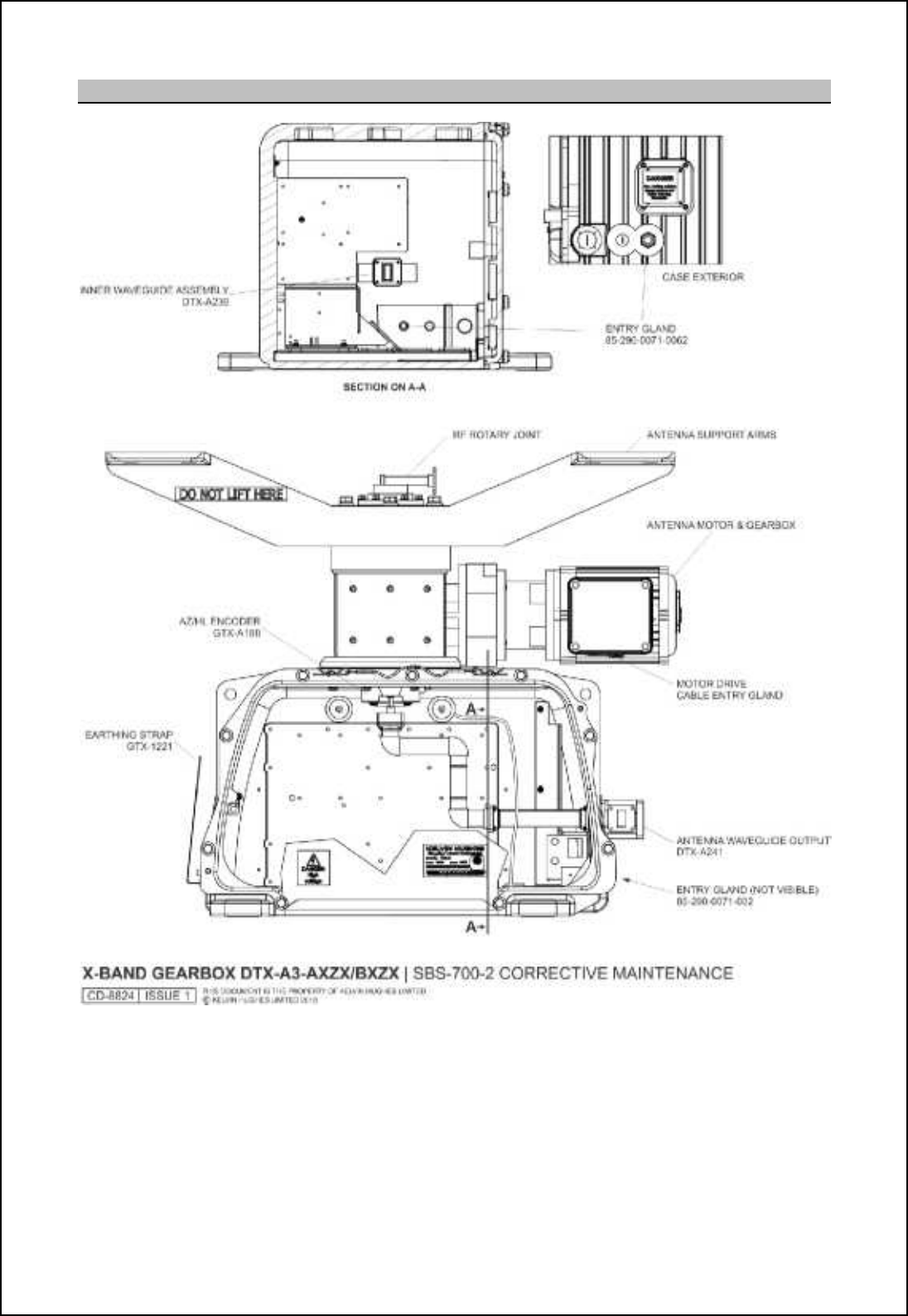
SBS-900 Shore Based Radar Systems
Chapter 10: Corrective maintenance
KH-1602-2 issue 1: Standard SBS900 Systems Operator & Maintenance Handbook
Page 129 of 240
10.3.4 Internal layout
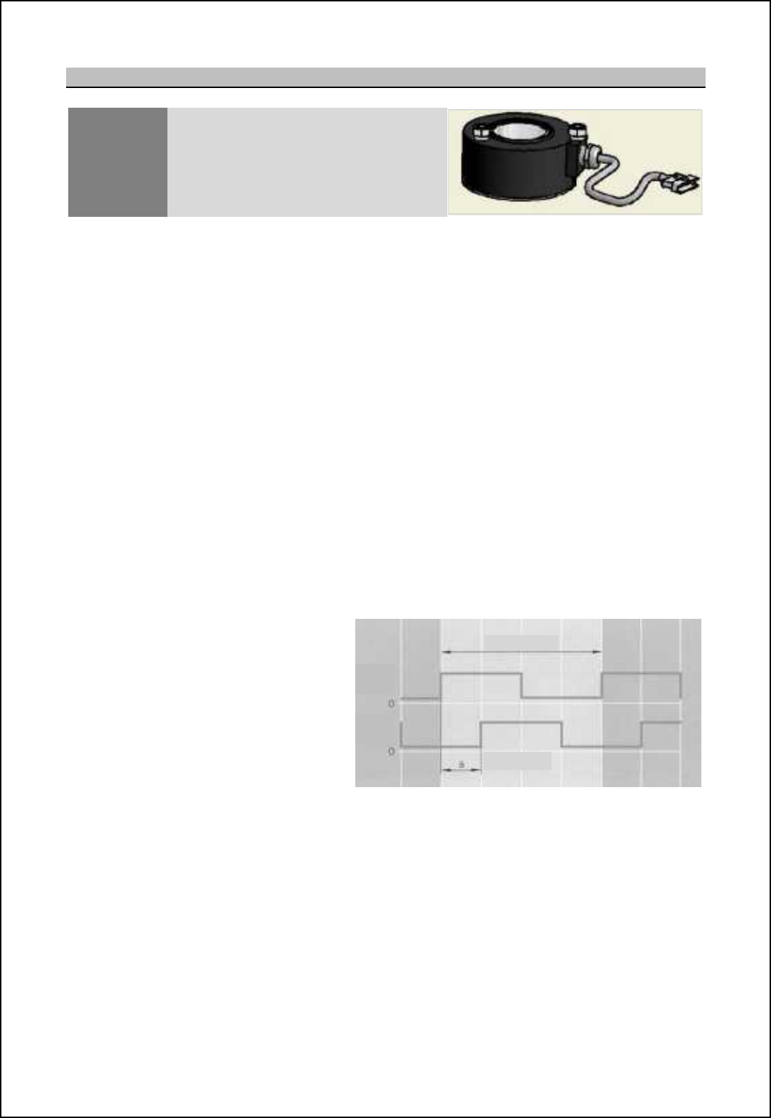
10.3.5 ACP/ARP encoder
GTX-A188 Optical quadrature azimuth and heading
line encoder
The sealed ACP/ ARP encoder is situated inside the gearbox housing and is located around the
rotating joint shaft. It outputs 1024 pulses (two azimuth streams 90deg phase shifted and two inverse
azimuths) per revolution.
The encoder also outputs a heading line pulse and an inverse heading line pulse for each revolution
of the antenna. The azimuth, heading line output signals and DC power input are connected to TB1
which is internally located in the base of the gearbox.
The encoder is supplied with +15V DC supply from the transceiver enclosure.
The Quadrature ACP comprises of two 90° phase shifted square wave pulse trains ACP1 & ACP2
whose frequency is dependent on antenna rotation rate.
- 1024 ACP pulses are required per 360° antenna rotation from each pulse train.
- ACP2 lags ACP1 by 90° for an antenna rotating clockwise when viewed from above.
-The output pulses have an amplitude of +15V.
Each rising or falling edge is decoded from these two pulse trains to provide 4096 ACPs per antenna
revolution.
The ARP pulse width is required to be equal to at least one 4096 decoded period but does not have to
have any specific timing in relation to ACPs i.e. it can be asynchronous w.r.t ACPs.
Polarity : Positive
Stabilisation : Relative
Format :1024 bi-phase quadrature
ACP & ARP
Ratio : 1:1 with scanner rotation
Amplitude : 5V to 15V differential
Impedance 9 Hhni 0e|
')$8 # %$&(
*.-%
*+-&
-3/61 63427
Note: The azimuth encoder is a sealed unit and contains no field serviceable or repairable parts.
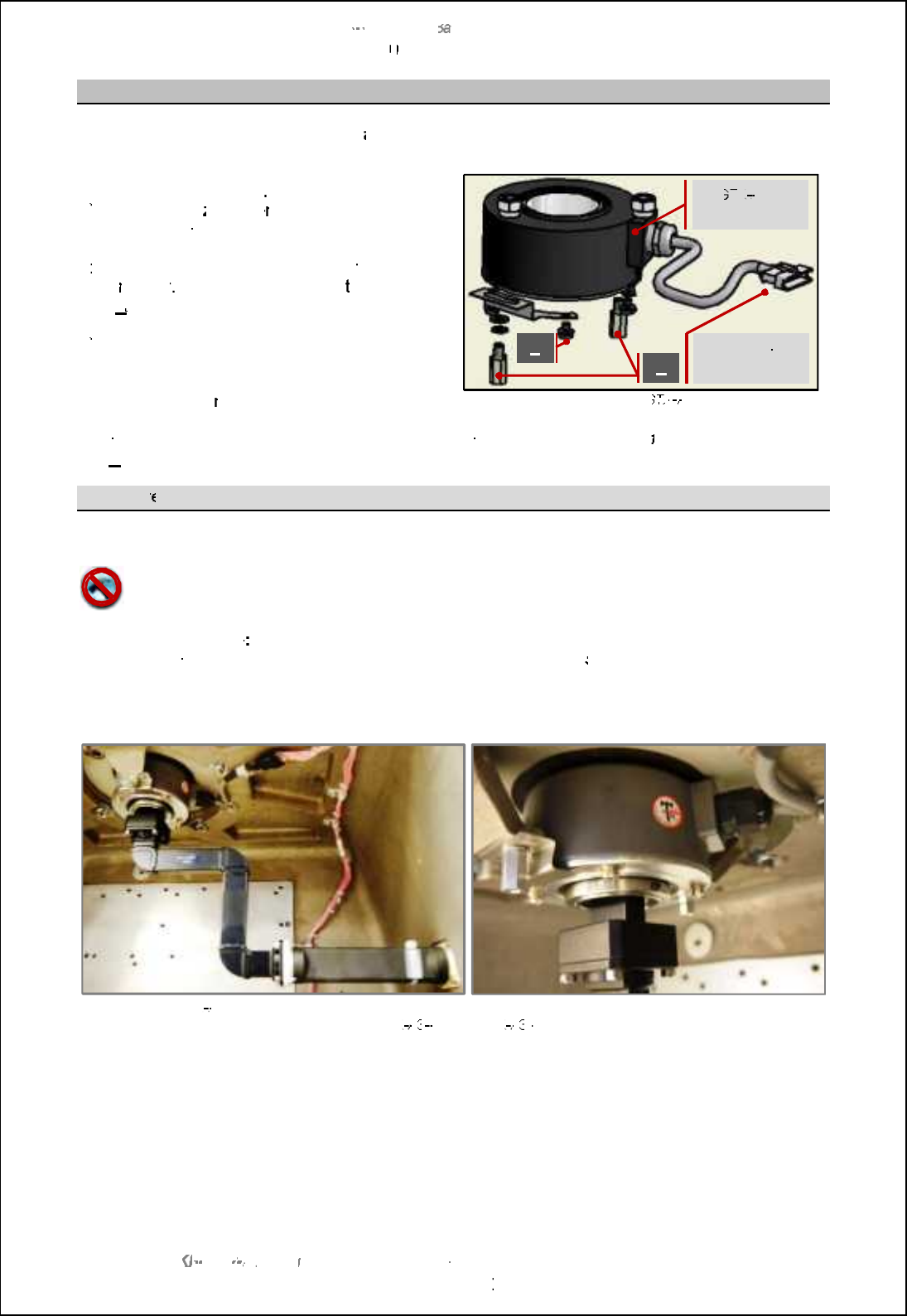
SBS
-
900 Shore
Ba
Ba
sed
Radar Systems
Chapter
10
10
:
Corrective maintenance
KH
KH
-
1602 2
issue 1
:
Standard SBS900 Systems Operator & Maintenance Handbook
Page
131
of
240
Encoder
removal
The
azimuth encoder
can be removed
as follows:
a)
a)
Fully isolate the
entire system from all
sources of AC power
b)
b)
Unplug the
a
zimuth
e
ncoder flying lead from
the housing cable form (located in the top of
the housing).
c)
c)
Noting the position and order of w
ashers,
u
nscrew
, remove and retain
the
two pillars
(
A
)
that hole mounting bracket
from the base
of
the rotating joint.
d)
d)
Slacken the two M3 (1.5mm hex key) grub
screws securing the azimuth encoder to the
gearbox and carefully remove the azimuth
encoder, ensu
ring the cable is not damaged.
Example of G
TX
TX
A188
Noting the position and order of washers, unscrew, remove and retain
the
four
cross head bolts
(
B
)
that retain the supporting bracket to the encoder.
Encoder r
eplacement
To replace the azimuth encoder, reverse the removal procedure shown above.
The encoder must never be hammered into position.
Using a hammer to fit the encoder can damage the
device.
Heading Marker Note
There is no heading orientation mark on the encoder. When a replacement
encoder is fitted the heading line must be configured/ adjusted in the
setup
menu of the radar
distribution unit.
GTX
A188 encoder and waveguide
Detail of encoder mounting
DTX
A3
A3
-
AXZX & DTX A3
A3
-
BXZX
Power & signal
connection
G
TX
TX
A188
encoder
A
B
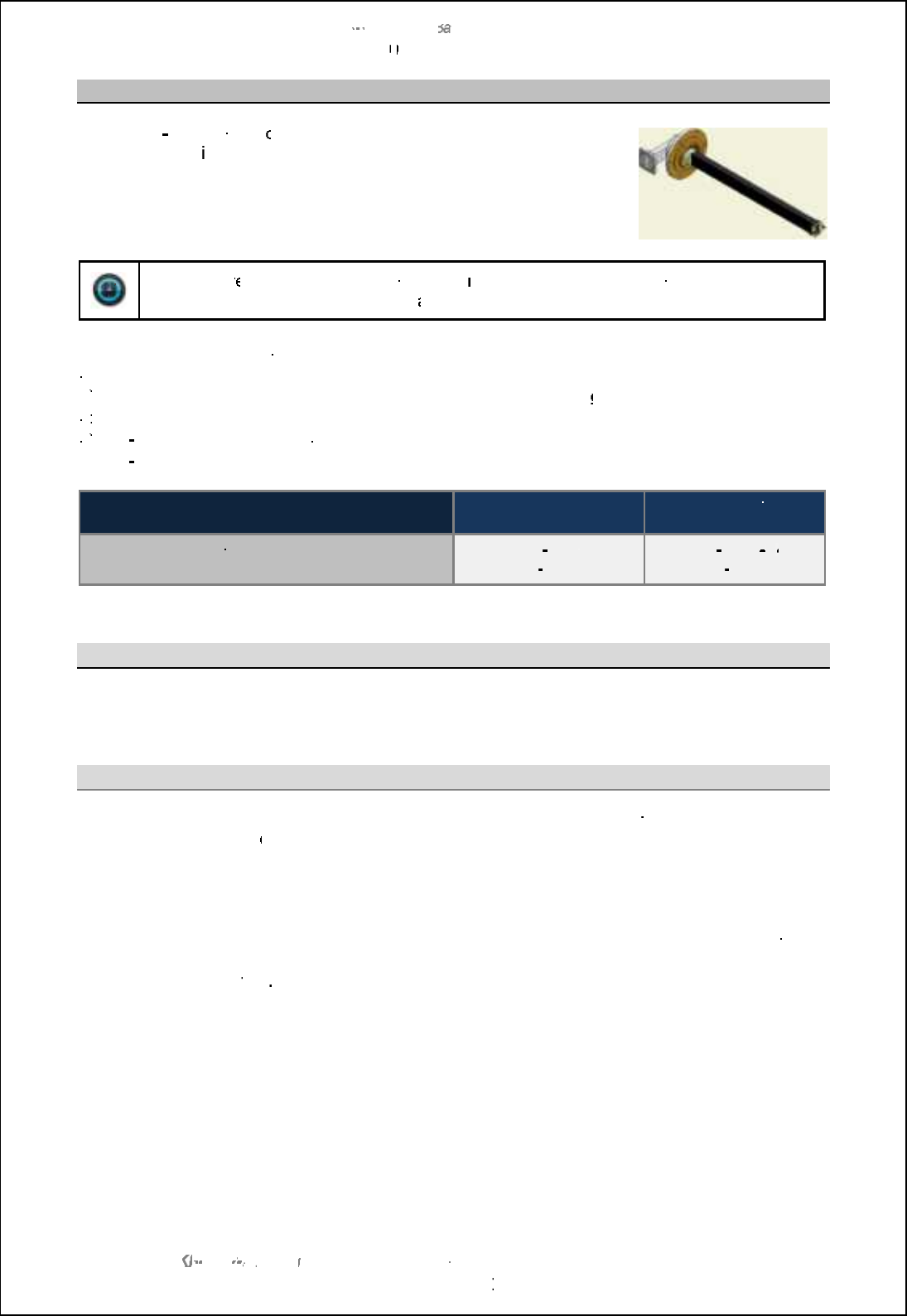
SBS
-
900 Shore
Ba
Ba
sed
Radar Systems
Chapter
10
10
:
Corrective maintenance
KH
KH
-
1602 2
issue 1
:
Standard SBS900 Systems Operator & Maintenance Handbook
Page
132
of
240
10.3.6
RF rotary joint
The
RF
RF
•Qi
- MfMPPMR?PWH
oint is the mechanism by which the RF
from the wavegu
ide is
coupled to the rotating antenna waveguide.
The joint is secured to the centre of the
swing casting
and connects
to the waveguide on the
underside of the antenna.
Time:
The r
emoval and replacement of the
rotating joint
can take between
4 to
5
hours to
complete depending on accessibility
and availability of lifting equipment
.
There are a number of tasks involved in the removal and replacement of the rotating joint:
a)
a)
Removal of the antenna
b)
b)
Removal of the RF coupling and azimuth encoder from within the
gearbox
housing
c)
c)
Removal and replacement of the rotating joint
d)
d)
Re
Re
-
assembly of the RF coupling and azimuth encoder
e)
e)
Re
Re
-
installation of the antenna
Spares required
Casing colour
Signal white
Casing colour
Silver Grey
Replacement rotating joint
Rotating joint gasket
DTX
-
A183
GTX
-
A1246
DTX
-
A183
64
64
GTX
-
A1246
Antenna removal
See section
10.3.1
for the precautions and instructions on removing the antenna.
RF coupling and encoder removal
Coupling:
Within the gearbox enclosure, disconnect the base of the Ro
-
Jo from the inner
wavegui
de assembly.
Ensure the inner waveguide is suitably supported to prevent any stress on retaining
fasteners.
Encoder:
Prior to removing the rotating joint, it is necessary to remove the azimuth encoder
from the inside of the gearbox housing.
Full details can be found in section
10.3.5
page
130
.
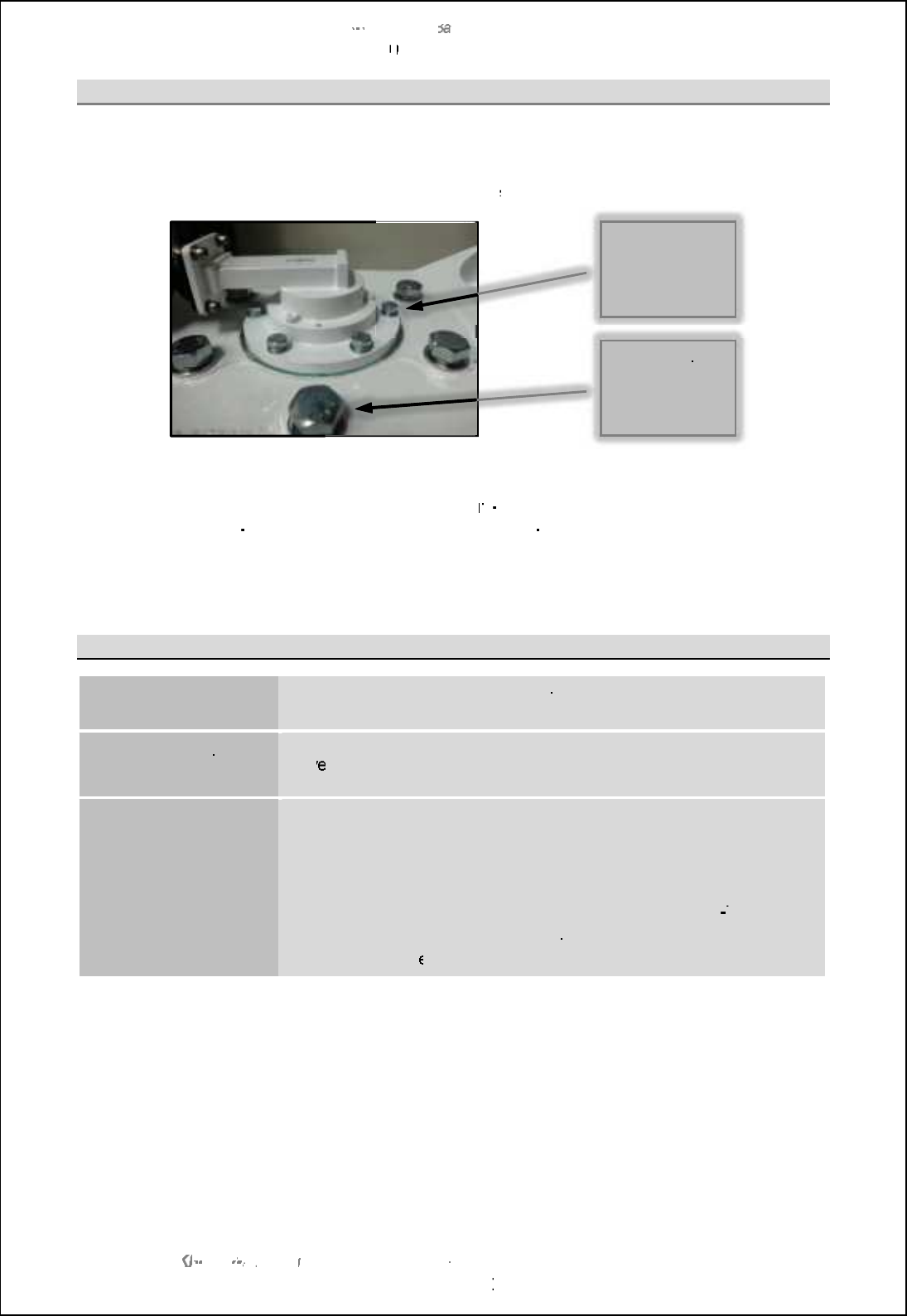
SBS
-
900 Shore
Ba
Ba
sed
Radar Systems
Chapter
10
10
:
Corrective maintenance
KH
KH
-
1602 2
issue 1
:
Standard SBS900 Systems Operator & Maintenance Handbook
Page
133
of
240
Rotating joint removal
With the antenna, internal waveguide and azimuth encoder removed, the rotating joint can now be
removed.
Noting their positions, remove
and retain
the 6 x M12 bolt
s and washers shown below:
The entire rotating joint can now be gently removed from the transceiver housing.
Remove and discard the gasket which MUST NOT be
re
re
-
used. A replacement gasket ordered with
the rotating joint (GTX
-
A1246) must be used when the new Ro
-
Jo is assembled.
This completes the removal process.
Replacement
Rotating joint
To replace the rotating joint, reverse the above procedure
using the
new GTX
-
A1246 replacement
gasket
.
Waveguide coupling
& azimuth encoder
Rev
erse the removal process.
Antenna
Reverse the removal procedure detailed in the above section.
-
Tighten and torque load the 12 antenna retaining bolts to 56 Nm and
apply
Loctite 222 on their threads during assembly.
-
Waterproof the waveguide joint by sealing with a layer of greased
NJ?QRGAAMK NMSLBQSAF?Q+ CLJCWfQAMK NMSLBMP' CLQM
Tape.
-
After installation, the antenna should be checked to ensure that it
can freely rotat
e without obstruction.
6 x M12 bolts
and washers
DO NOT
REMOVE
the 6 larger
bolts
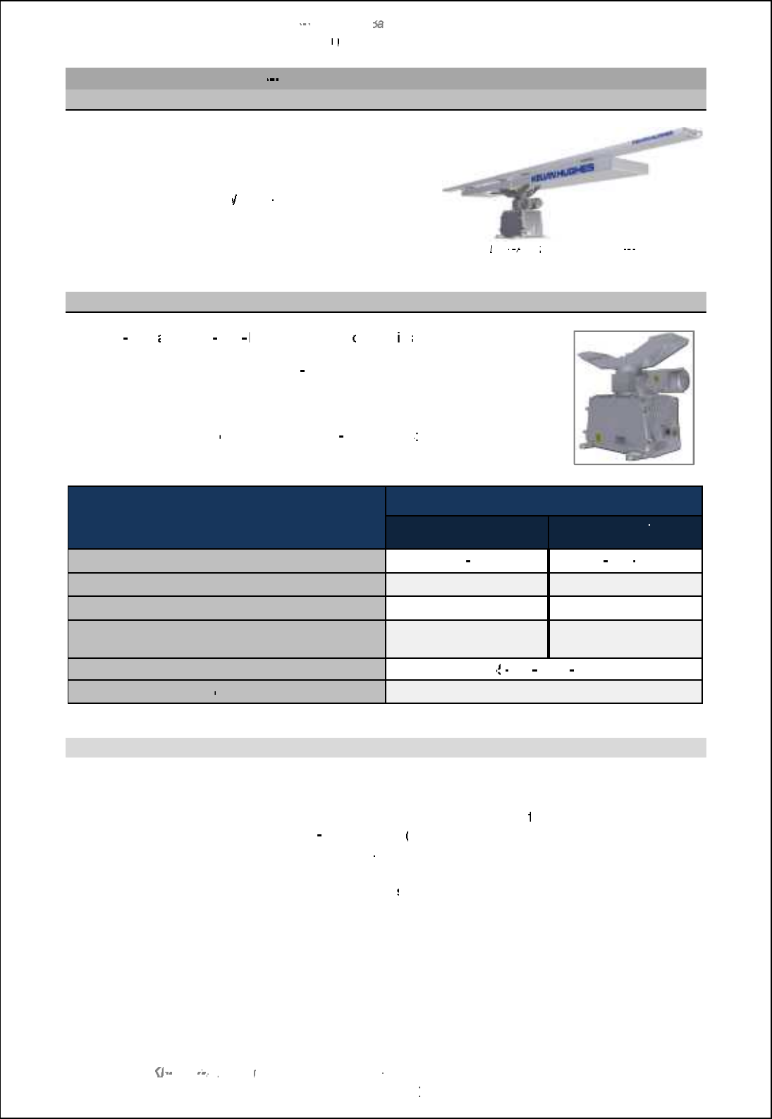
SBS
-
900 Shore
Ba
Ba
sed
Radar Systems
Chapter
10
10
:
Corrective maintenance
KH
KH
-
1602 2
issue 1
:
Standard SBS900 Systems Operator & Maintenance Handbook
Page
134
of
240
10.4
Standard dual
X & S
-
band
10.4.1
Antenna
The corrective maintenance
for the standard
LPA
-
A455 Low Profile Antennas is restricted to
cleaning and inspecting for damage.
See
Planned Maintenance
Annual Maintenance
for cleaning and inspection details.
Standard
DTX
A19
fitted with an LPA
-
A455
10.4.2
Gearbox
The
DTX
-
A19
and
DTX
-
A19
BAAA gearbox h
ousing
is
a cast enclosure with
a
service
cover
that allows access to the
azimuth/ heading line (ACP/ ARP)
encoder and it connections and the S
band flexwell connection.
There are no other electronic assemblies within the gearbox casing.
The
gearbox
comprises
of
the following
sub
-
assemblies
X Band system description
Part number
Casing colour
Signal
white
Casing colour
Silver Grey
Complete assembly
DTX
-
A19
DTX
-
A19
-
BAAA
Antenna motor / gearbox assembly
TBC
TBC
Motor coupling gasket
TBC
TBC
RF rotary Joint
Rotating joint gasket
TBC
TBC
Service access door seal
55
55
-
100
-
0311
001
Azimuth/ heading line
quadrature encoder
TBC
Maintenance details
Section under construction
Please consult Kelvin Hughes for maintenance procedures for the
following equipment:
DTX
-
A19 gearbox
(all variants)
LPA
-
A455
antenna (all variants)
Contact details can be found in
section 12 of this handbook.
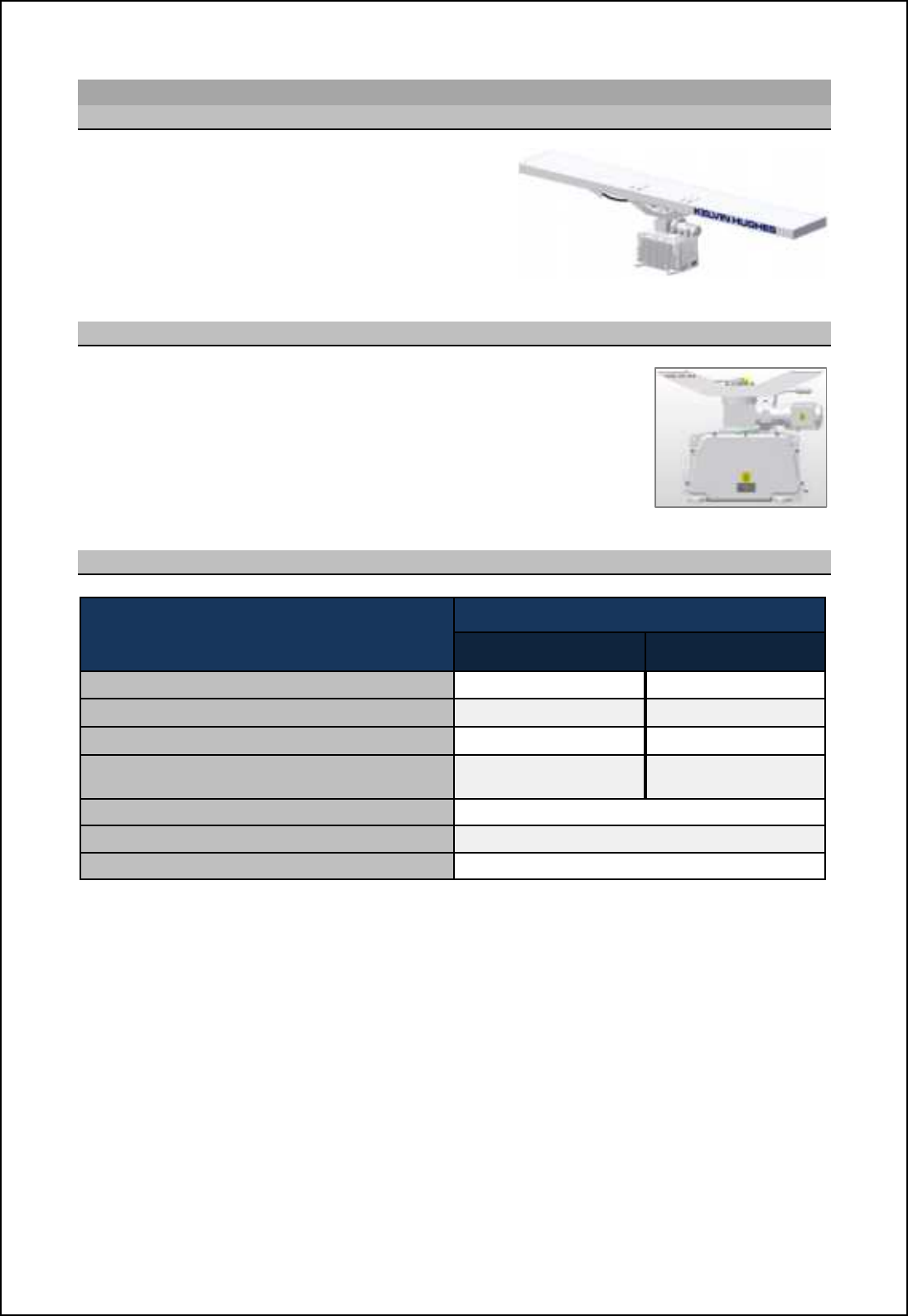
SBS-900 Shore Based Radar Systems
Chapter 10: Corrective maintenance
KH-1602-2 issue 1: Standard SBS900 Systems Operator & Maintenance Handbook
Page 135 of 240
10.5 Standard S-band
10.5.1Antenna
The corrective maintenance for the standard
LPA-A3 and LPA-A3-BAAA Low Profile Antennas
is restricted to cleaning and inspecting for
damage.
See Planned Maintenance/Annual Maintenance
for cleaning and inspection details. Standard GTX-A11 fitted with an LPA-A3
10.5.2 Gearbox
The GTX-A11 and GTX-A11-BAAA gearbox housing is a cast enclosure
with a service cover that allows access to the azimuth/ heading line (ACP/
ARP) encoder and it connections and the S-band flexwell connection.
There are no other electronic assemblies within the gearbox casing.
The gearbox comprises of the following sub-assemblies:
10.5.3Spares listing
X Band system description Part number
Casing colour
Signal white
Casing colour
Silver Grey
Complete assembly GTX-A11 GTX-A11-BAAA
Antenna motor / gearbox assembly TBC TBC
Motor coupling gasket TBC TBC
RF rotary Joint
Rotating joint gasket TBC TBC
Service access door seal 55-100-0311-001
Azimuth/ heading line quadrature encoder TBC
Door seal 55-100-0311-001

SBS-900 Shore Based Radar Systems
Chapter 10: Corrective maintenance
KH-1602-2 issue 1: Standard SBS900 Systems Operator & Maintenance Handbook
Page 136 of 240
10.5.4 ACP/ARP encoder
GTX-A188 Optical quadrature azimuth and heading
line encoder
The sealed ACP/ ARP encoder is situated inside the gearbox housing and is located around the
rotating joint shaft. It outputs 1024 pulses (two azimuth streams 90deg phase shifted and two inverse
azimuths) per revolution.
The encoder also outputs a heading line pulse and an inverse heading line pulse for each revolution
of the antenna. The azimuth, heading line output signals and DC power input are connected to TB1
which is internally located in the base of the gearbox.
The encoder is supplied with +15V DC supply from the transceiver enclosure.
The Quadrature ACP comprises of two 90° phase shifted square wave pulse trains ACP1 & ACP2
whose frequency is dependent on antenna rotation rate.
- 1024 ACP pulses are required per 360° antenna rotation from each pulse train.
- ACP2 lags ACP1 by 90° for an antenna rotating clockwise when viewed from above.
-The output pulses have an amplitude of +15V.
Each rising or falling edge is decoded from these two pulse trains to provide 4096 ACPs per antenna
revolution.
The ARP pulse width is required to be equal to at least one 4096 decoded period but does not have to
have any specific timing in relation to ACPs i.e. it can be asynchronous w.r.t ACPs.
Polarity : Positive
Stabilisation : Relative
Format :1024 bi-phase quadrature
ACP & ARP
Ratio : 1:1 with scanner rotation
Amplitude : 5V to 15V differential
Impedance 9 Hhni 0e|
')$8 # %$&(
*.-%
*+-&
-3/61 63427
Note: The azimuth encoder is a sealed unit and contains no field serviceable or repairable parts.
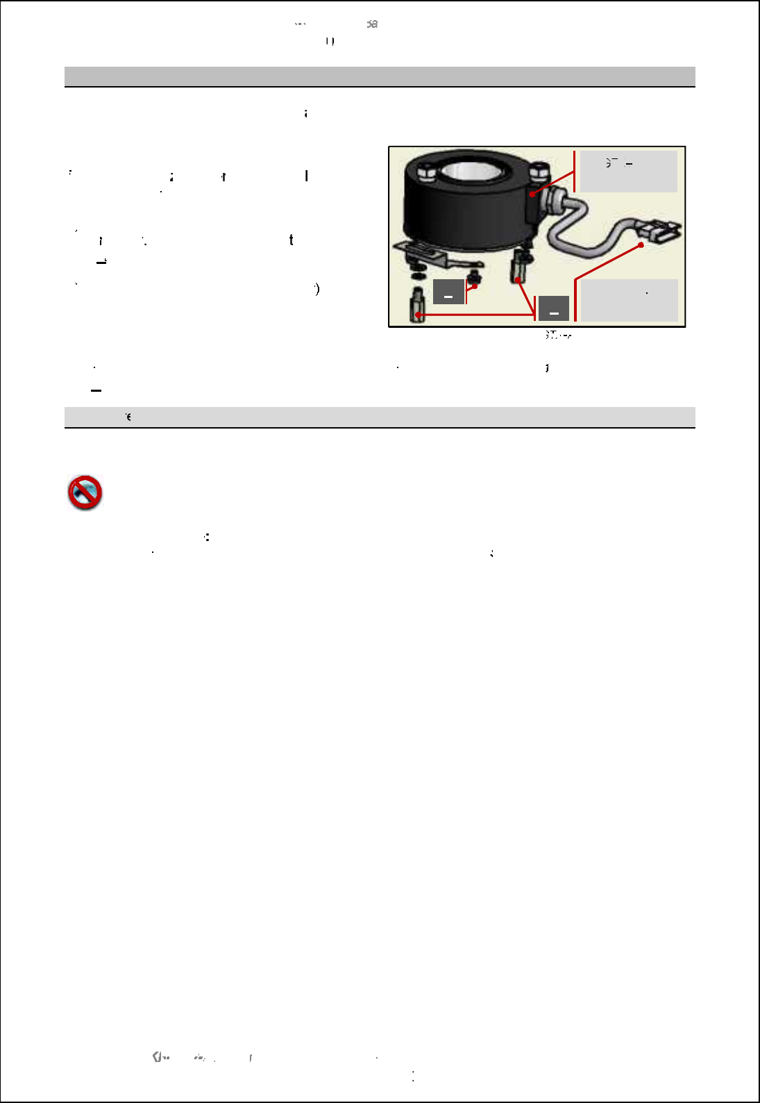
SBS
-
900 Shore
Ba
Ba
sed
Radar Systems
Chapter
10
10
:
Corrective maintenance
KH
KH
-
1602 2
issue 1
:
Standard SBS900 Systems Operator & Maintenance Handbook
Page
137
of
240
Encoder removal
The
azimuth encoder
can be removed
as follows:
e)
e)
Fully isolate the entire system from all
sources of AC power.
f)
f)
Unplug the
a
zimuth
e
ncoder flying
lead from
the housing cable form (located in the top of
the housing).
g)
g)
Noting the position and order of washers,
u
nscrew
, remove and retain
the
two pillars
(
A
)
that hole mounting bracket
from the base
of
the rotating joint.
h)
h)
Slacken the two M3 (1.5mm hex key
) grub
screws securing the azimuth encoder to the
gearbox and carefully remove the azimuth
encoder, ensuring the cable is not damaged.
Example of G
TX
TX
A188
Noting the position and order of washers, unscrew, remove and retain
the
four
cross head bolts
(
B
)
that retain the supporting bracket to the encoder.
Encoder r
eplacement
To replace the azimuth encoder, reverse the removal procedure shown above.
The encoder must never be hammered into position.
Using a hammer to fit the encoder can damage the device.
Heading Marker Note
There is no heading orientation mark on the encoder.
When a replacement
encoder is fitted the heading line must be configured/ adjusted in the
setup
menu of the radar
distribution unit.
Power & signal
connection
G
TX
TX
A188
encoder
A
B
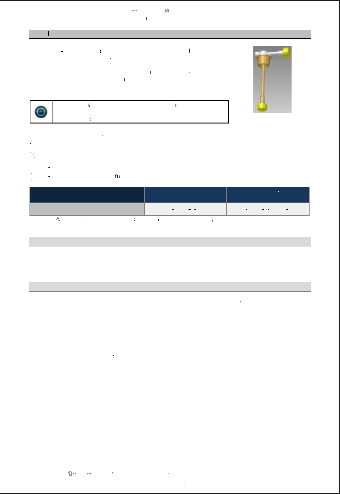
SBS
-
900 Shore
Ba
Ba
sed
Radar Systems
Chapter
10
10
:
Corrective maintenance
KH
KH
-
1602 2
issue 1
:
Standard SBS900 Systems Operator & Maintenance Handbook
Page
138
of
240
10.5.5
RF rotary joint
The
RF
RF
•Qi
- MfMPPMR?PWH
oint is the mechanism by which t
he RF
from
the transceiver waveguide is
coupled to the rotating antenna waveguide.
The joint is secured to the centre of the cast
ing swing casting
and
connects to the waveguide on the
underside of the antenna.
Time:
The r
emoval and replacement of the
rotating joint
can
take between
4 to
5 hours to complete depending on
accessibility
and availability of lifting equipment
.
Example of rotating joint with
yellow transit caps fitted
There are a number of tasks involved in the removal and replacement
of the rotating joint:
f)
f)
Removal of the antenna
g)
g)
Removal of the RF coupling and azimuth encoder from within the transceiver housing
h)
h)
Removal and replacement of the rotating joint
i)
i)
Re
Re
-
assembly of the RF coupling and azimuth encoder
j)
j)
Re
Re
-
installation of the anten
na
na
Spares required
Casing colour
Signal white
Casing colour
Silver Grey
Replacement rotating joint
GTX
-
A150
2
-
S
Note
Note
GTX
-
A150
2
-
BAAA
S
Note
Note
Note:
The R
otating joint
is delivered in kit form
containing
the ro
-
jo, a
replacement
gasket and coupling bullet.
Antenna removal
See section
10.2.4
for the precautions and instructions on removing the antenna.
RF coupling and encoder removal
Coupling:
Within the gearbox enclosure, disconnect the base of the Ro
-
Jo from the inner
waveguide assembly.
Ensure the inner waveguide is suitably supported to prevent any stress on retaining
fasteners.
Encoder:
Prior to removing the rotating joint, it is necessary to remove the azimuth encoder
from the inside of the gearbox housing.
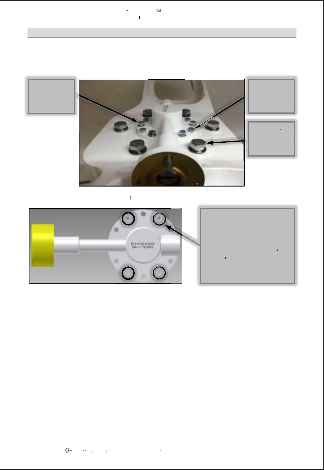
SBS
-
900 Shore
Ba
Ba
sed
Radar Systems
Chapter
10
10
:
Corrective maintenance
KH
KH
-
1602 2
issue 1
:
Standard SBS900 Systems Operator & Maintenance Handbook
Page
139
of
240
Rotating joint removal
With the antenna, internal RF coupling and azimuth encoder removed, the rotating joint can now be
removed.
Noting their positions and thread depths, remove
and retain
the bolts and washers shown below:
Take four of the M6 x 20mm bolts and
refit them into the holes used by the M6 x 6mm bolts
When loosened
,
the entire rotating joint can be gently removed from the housing.
Remove and discard the gasket which MUST NOT be reused. A replacement can be found in
the
spares kit.
This completes the removal process.
4 off
M6 x 6mm
bolts with no
washers
6 off
M6 x 20mm
bolts with
washers
DO NOT
REMOVE
the 6 larger
bolts
The holes that contained the
four M6 x 6mm bolts are
threaded.
Place four M6 x 20mm bolts into
these threaded holes and g
ently
tighten
each of the bolts in turn,
this will push the rotating joint
out of the housing.

SBS-900 Shore Based Radar Systems
Chapter 10: Corrective maintenance
KH-1602-2 issue 1: Standard SBS900 Systems Operator & Maintenance Handbook
Page 140 of 240
Replacement
Rotating joint To replace the rotating joint, reverse the above procedure using the replacement
gasket+ \off_n [h^ N lcha `ioh^ ch nb_ mj[l_m ecn-
RF coupling
& azimuth
encoder Reverse the removal process shown in section 10.5.4 pages 136 onwards.
Antenna
Reverse the removal procedure detailed in the above section.
-Dhmol_ nb_ l_jf[]_g_hn \off_n [h^ N lcha [l_ ]ill_]nfs chmn[ff_^ ch nb_
waveguide junction between the ro-jo and the antenna waveguide.
To avoid SharpEyeTM SWR errors at start up, ensure that ALL connectors are
correct and secure. Pay particular attention to the coupling bullets, Ro-Jo to
Flexi Waveguide & Co-Ax Adaptor.
- Tighten and torque load the 12 antenna retaining bolts to 56 Nm and apply
Loctite 222 on their threads during assembly.
- Waterproof the waveguide joint by sealing with a layer of greased plastic
]igjioh^ mo]b [m G_hf_sm ]igjioh^ il C_hmi-Tape.
- After installation, the antenna should be checked to ensure that it can freely
rotate without obstruction.
SBS-900 Shore Based Radar Systems
Chapter 10: Corrective maintenance
KH-1602-2 issue 1: Standard SBS900 Systems Operator & Maintenance Handbook
Page 141 of 240
10.6 Advanced antenna sub systems
Enhanced ATU and antennas: The corrective
maintenance procedures for the advanced
ST1-F10/ 20 Antenna Turning Unit (ATU) and
range of antennas are not detailed in this
section. ST1-F20 Antenna Turning Unit & antenna
Please refer to the installation and maintenance handbook supplied with the equipment for full details
on corrective maintenance.
Spares: Where required, only Kelvin Hughes approved spares must be used. The use
of unapproved spares can invalidate the warranty status of the unit or lead to
a failure of the system.
Adverse weather: It is strongly recommended that the gearbox inspections noted in section 9.4
are carried out at the earliest safe opportunity after the system has been
exposed to severe or adverse weather conditions.
Health & safety: All safety warnings for the system noted in section 2 must be observed at all
times when inspecting and maintaining any part of the SBS system or its
associated sub systems.
System isolation: Please refer to section 9.3 page 87 for details on isolating the system from all
sources of AC power.
WARNING
Lethal voltages are present within the equipment.
All maintenance procedures must be carried out with all relevant power sources switched
OFF, fully isolated and disconnected.
Caution: When the system has been operating in strong sunlight or elevated
temperatures, gearbox casings and antenna surfaces will be extremely hot.
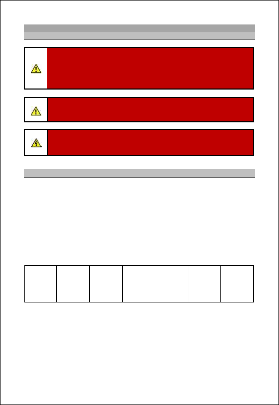
SBS-900 Shore Based Radar Systems
Chapter 10: Corrective maintenance
KH-1602-2 issue 1: Standard SBS900 Systems Operator & Maintenance Handbook
Page 142 of 240
10.7 Transceiver enclosure
10.7.1 Safety notices
ANTENNA ROTATION SAFETY NOTICE:
When three-phase power is connected to the system and switched ON, the antenna may
rotate immediately regardless of the RUN command status.
Use the Antenna Rotation keyswitch, Man Aloft safety switches or antenna control in the
command and display system to stop antenna rotation in an emergency.
WARNING: Prior to commencing any maintenance procedure, users must familiarise
themselves with the health & safety warnings noted in the planned maintenance and
health and safety sections of the system handbooks.
AC supplies: Prior to carrying out any maintenance, the system must be fully isolated
and disconnected from the single and 3-phase AC supplies. This must include the full
isolation of any UPS supplies connected to the system.
10.7.2 System Part numbering
A number of options can be specified for the DTX-A7-* SBS-900 transceiver enclosure.
Currently, these options can be factory fitted or retro fitted in the field.
In order that the equipment can be ordered correctly, built & identified and supported in the
future with any valid number of options, the equipment part number is to be suffixed by a 6-
digit option number as below when an option is fitted:
The option code contains a digit for each available option, where:
'0= Indicates the option is not required, not fitted or not available.
'1= Indicates the option is required or fitted.
'n= Indicates the particular type of option is required or fitted.
DTX-A7-*- 0 = Not fitted Not
allocated.
Reserved for
future use
Not
allocated.
Reserved for
future use
Not
allocated.
Reserved for
future use
Not
allocated.
Reserved for
future use
0 = Not
applicable
SBS-900
FAN KIT ,
SBS-A179
Project
Specific
Option,
(
see below
)
Example: DTX-A7-3-200000 is an SBS900-3 Transceiver Enclosure with two optional
fan kits fitted (dual transceiver).
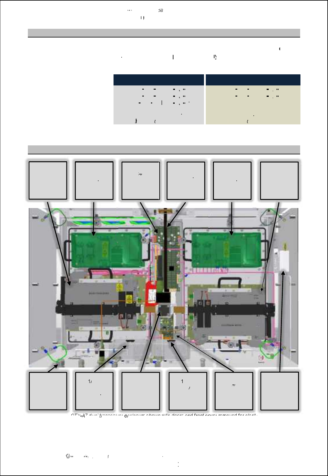
SBS
-
900 Shore
Ba
Ba
sed
Radar Systems
Chapter
10
10
:
Corrective maintenance
KH
KH
-
1602 2
issue 1
:
Standard SBS900 Systems Operator & Maintenance Handbook
Page
143
of
240
10.7.3
AC Input
& breakers
Single Phase AC supply:
Depending on the system, t
he transceiver enclosure receives
one or
two sources of
single
phase
AC
supp
ly from
the Radar Distribution
unit.
AC
Mains input A
AC
Mains input A & B
SBS
-
900
-
1
DTX
-
A7
A7
-
1
SBS
-
900
-
3
DTX
-
A7
A7
-
3
SBS
-
900
-
2
DTX
-
A7
A7
-
2
SBS
-
900
-
4
DTX
-
A7
A7
-
4
SBS
-
900
-
51
DTX
-
A7
A7
-
51
51
The AC input terminates on
RH
RH
-
TB1
(right
hand side)
The AC input terminates on
LH
LH
-
TB1
(left hand side)
10.7.4
Overview
DTX
A7
A7
dual
transceiver
e
nclosure
shown with doors
and front cover
removed for clarity
SBS
A126
Control &
BITE PCA
TB1
/ MCB1
LH AC
Connection
& breaker
Tx A
6F?PN( WC\
processor
DTX
A295
Quadrature
Buffer PCA
Waveguide
to antenna
TB
TB
1 / MCB2
RH
AC
connection &
breaker
Cable entries
Power
supply unit
for Tx A
Power
supply unit
for Tx B
Tx B
6F?PN( WC\
processor
Service AC
socket
(50W max)
Waveguide
switch (dual
systems
only)

SBS-900 Shore Based Radar Systems
Chapter 10: Corrective maintenance
KH-1602-2 issue 1: Standard SBS900 Systems Operator & Maintenance Handbook
Page 144 of 240
Page intentionally blank
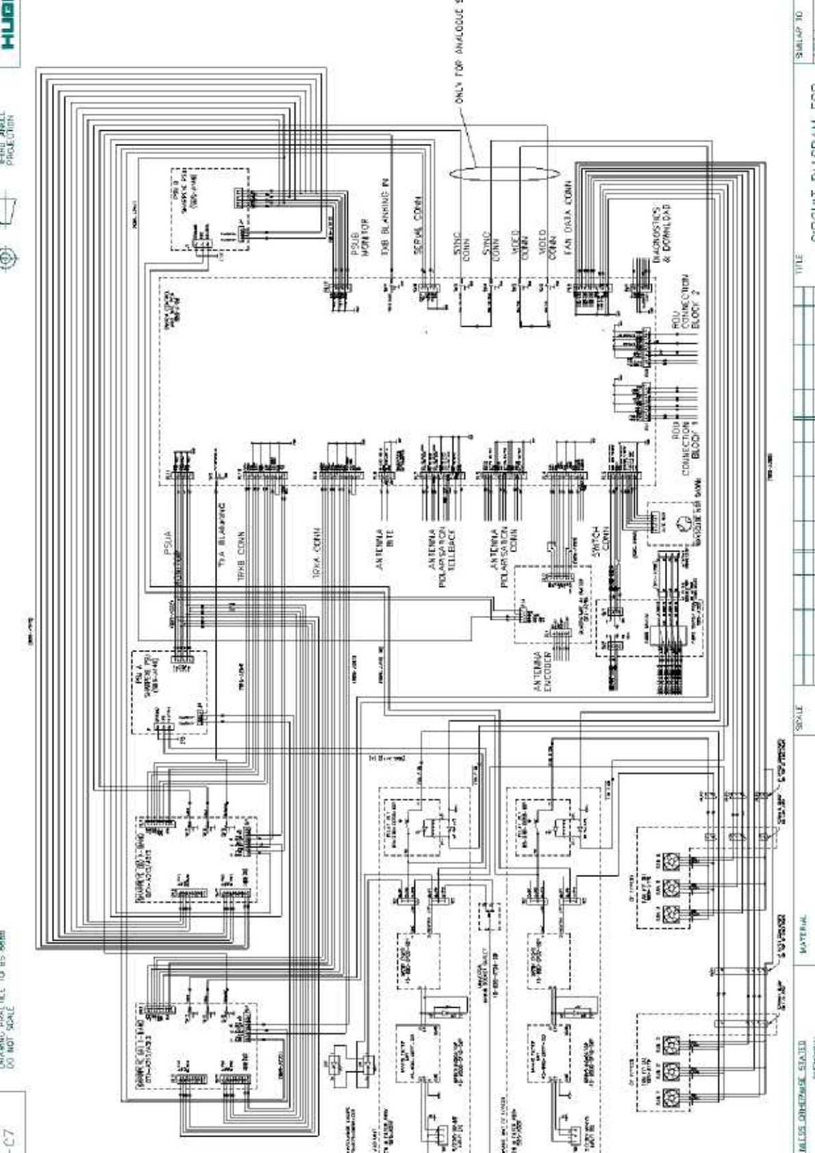
Page Intentionally Blank
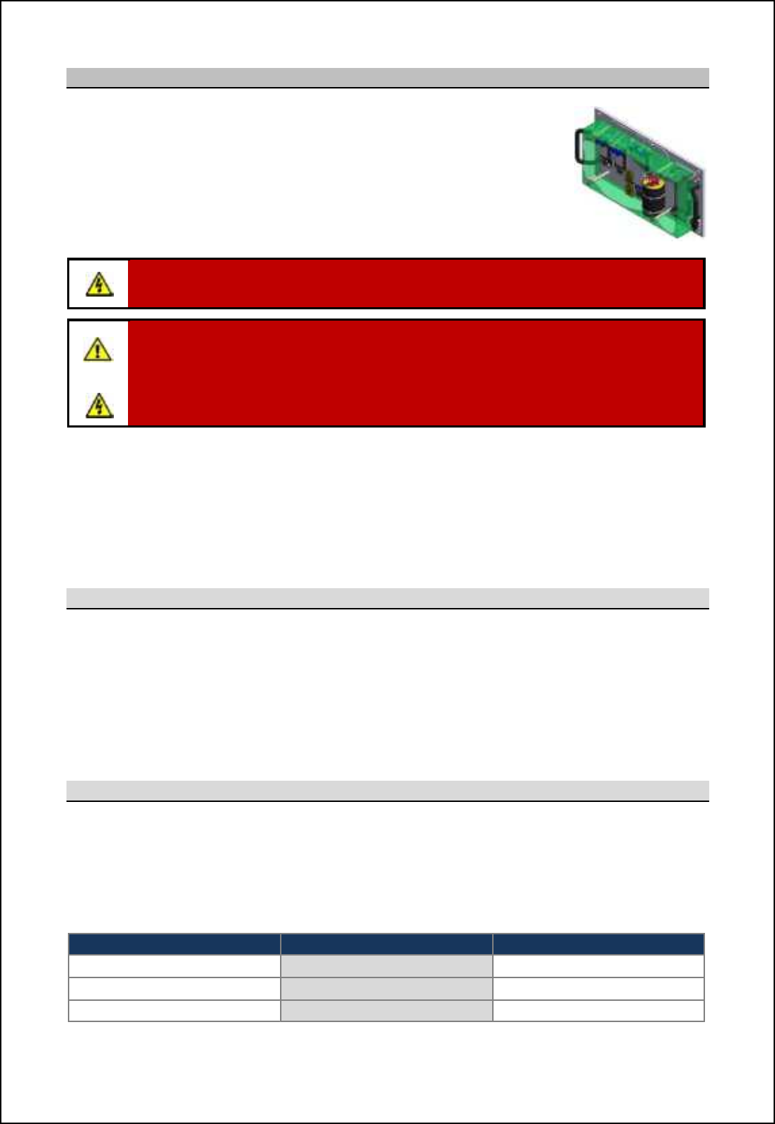
SBS-900 Shore Based Radar Systems
Chapter 10: Corrective maintenance
KH-1602-2 issue 1: Standard SBS900 Systems Operator & Maintenance Handbook
Page 147 of 240
10.7.6 Power unit assembly
AC-DC power supply unit
Part number SBS-A146
The AC-DC power supply unit is a single assembly that provides the DC
outputs required by the transceiver enclosure.
The PSU assembly consists of a mains rectification unit and a number of DC/
DC converters mounted onto a chassis.
WARNING: Lethal AC and DC voltages of up to 450VDC are present within the SBS-
A146 assembly. Ensure the system is fully isolated prior to disconnecting the unit.
AC supplies: Prior to carrying out any maintenance, the system must be fully isolated
and disconnected from all single and 3-phase AC supplies. See system isolation in the
planned maintenance section of the system handbook.
UPS (Uninterruptable Power Supply): Where connected, ensure that UPS supplies to
the RDU are fully isolated prior to carrying out any maintenance task on the system.
Location: Depending on the system there will be one or two power units in the chassis.
Single transceiver systems: One PSU located in the left hand side of the
enclosure.
Dual transceiver systems: Two power supplies one on the left and another
on the right hand side of the enclosure.
10.7.6.1 Spares & repairs
The repair of the SBS-A146 is limited to unit replacement only.
- The power supply assembly contains no field serviceable or user adjustable parts.
- The unit must NOT be dismantled in the field as specialist equipment is required for testing the
electrical safety barriers.
- Circuit diagrams and sub assembly spares for the power unit assembly are not available.
10.7.6.2 Output checks
With the system switched ON, the voltages for the Transceiver Enclosure power supply can
be check using the menus on the RDU.
From the RDU front panel select Status then Enclosure.In the Enclosure menu, the
following power supply rails can be checked:
PSU A PSU B Internal supplies
PSU Tx A 3.3V PSU Tx A 3.3V PSU INT +15V
PSU Tx A 15V PSU Tx A 15V PSU INT +5.0V
PSU Tx A 13V PSU Tx A 13V
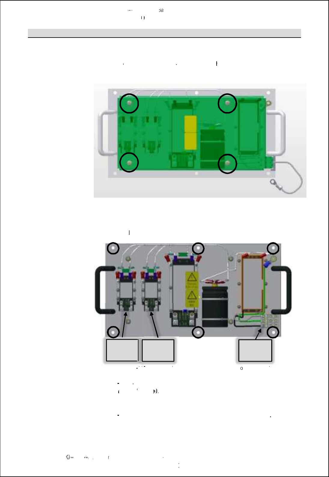
SBS
-
900 Shore
Ba
Ba
sed
Radar Systems
Chapter
10
10
:
Corrective maintenance
KH
KH
-
1602 2
issue 1
:
Standard SBS900 Systems Operator & Maintenance Handbook
Page
148
of
240
10.7.6.3
Removal & Replacement
Disconnection:
Ensure that the system is fully isolated from all
AC
power sources.
Remove th
e safety cover from the assembly; t
his
cover
is retained by four
nuts and washers
(circled below)
which will be required for refitting.
Carefully note the position and cable numbers of the input and output cables
indicated below
.
CAUTION:
T
he cable numbers are not detailed in this handbook.
SBSA
-
146 power supply assembly shown with safety c
o
ver removed
Removal:
The SBS
-
A146 assembly is retained into the enclosure by 6 nuts and
washers
(circled
above
)
.
Remove and retain these fasteners as they will be required for refitting.
The SBS
-
A146 assembly can now be removed from the enclosure
Replacement:
To replace the power supply, reverse the above removal process.
+15VDC
out
AC mains
input
+3.3VDC
out
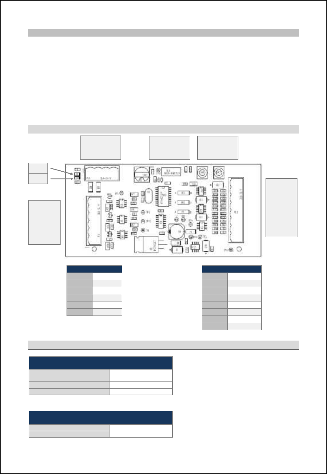
SBS-900 Shore Based Radar Systems
Chapter 10: Corrective maintenance
KH-1602-2 issue 1: Standard SBS900 Systems Operator & Maintenance Handbook
Page 149 of 240
10.7.7 DTX-A295 quadrature buffer PCB
The DTX-A295 converts pulsed 90:1 or 180:1 Azimuth and HL inputs into 4096 Quadrature differential
signals. The board uses a small processor to multiply the incoming Azimuth pulses in accordance with
the rate of turn detected.
Inputs are opto-coupled for signal integrity and isolation purposes.
The PCA is powered by the power supply located within the transceiver enclosure and can operate
from an input of between +12V to 24VDC. The PCA generates all required DC rails from the input
voltage with all rails being isolated (including GND) from the input supply.
10.7.7.1 PCB layout and connector details
PL1
PL2
PL1
-
1
ACP1
PL2
-
1
+12V
PL1
-
2
nACP1
PL2
-
2
ACP1
PL1
-
3
ACP2
PL2
-
3
nACP1
PL1
-
4
nACP2
PL2
-
4
ACP2
PL1
-
5
ARP
PL2
-
5
nACP2
PL1
-
6
nARP
PL2
-
6
ARP
PL2
-
7
nARP
PL2
-
8
GND/ 0V
10.7.7.2 LEDs
D1 (Green): Processor status
Processor running (Normal) Flashing at 1Hz
(0.5 sec ON and OFF)
No heading line LED ON for 2 seconds
No azimuth LED OFF for 2 seconds
Example: If the AZ OK but there is no HL then the LED will be ON for 2 seconds, OFF for
0.5 second, ON for 2 seconds etc.
D4 (Green): DC present
DC power ON ON
No DC power to PCB
OFF
PL1:
ACP &
ARP
IN
PL2:
ACP &
ARP
OUT
PL3
Programming
Download lead
SW1 & SW2
Not used in
normal service
PL4
Not used in
normal service
D1
D4
SBS-900 Shore Based Radar Systems
Chapter 10: Corrective maintenance
KH-1602-2 issue 1: Standard SBS900 Systems Operator & Maintenance Handbook
Page 150 of 240
10.7.7.3 Links and switches
Links Factory default position Optional settings
1, 2 & 3 A position
Direct buffer mode B position
Processor mode
4Open
Test mode disabled Made
Enables test mode (factory use only)
5,6 & 7 Open
Signal input filter disabled Made
Signal input filter enabled
8,9 &10 Open
Low input voltage signals disabled Made
Low input voltage signals enabled
Switches
SW1
SW2 Not used (factory use only)
SW3
0 Quad IN 4 90 Pulsed IN
Quad OUT
18192 Pulsed IN
Quad OUT 5Quad IN
4096 OUT
24096 Pulsed IN
Quad OUT 6 to F Spare/ not used
3180 Pulsed IN
Quad OUT
Note: When changing any links or switch settings, the PCA must be powered OFF/ ON to accept the
link setting changes.
10.7.7.4 Removal & replacement
Disconnection: Ensure that the DTX-A7 Transceiver Assembly is fully isolated from all
sources of AC power.
Noting their polarity, carefully disconnect PL1 and PL2.
Removal: The DTX-A265 PCA is retained onto the chassis by 4 nuts. Remove and
retain the nuts as they will be required for refitting.
The PCA may now be removed from the DTX-A7 enclosure.
Replacement: Ensure that all links and switches on the replacement board are set in the
same position as those on the PCA that has just been removed.
To replace the board reverse the removal process.
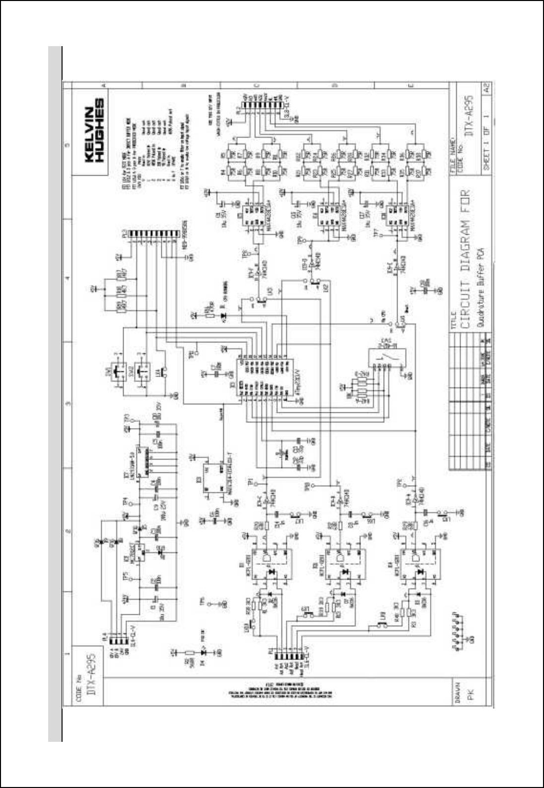
SBS-900 Shore Based Radar Systems
Chapter 10: Corrective maintenance
KH-1602-2 issue 1: Standard SBS900 Systems Operator & Maintenance Handbook
Page 151 of 240
10.7.7.5 Circuit diagram

SBS-900 Shore Based Radar Systems
Chapter 10: Corrective maintenance
KH-1602-2 issue 1: Standard SBS900 Systems Operator & Maintenance Handbook
Page 152 of 240
Page intentionally blank
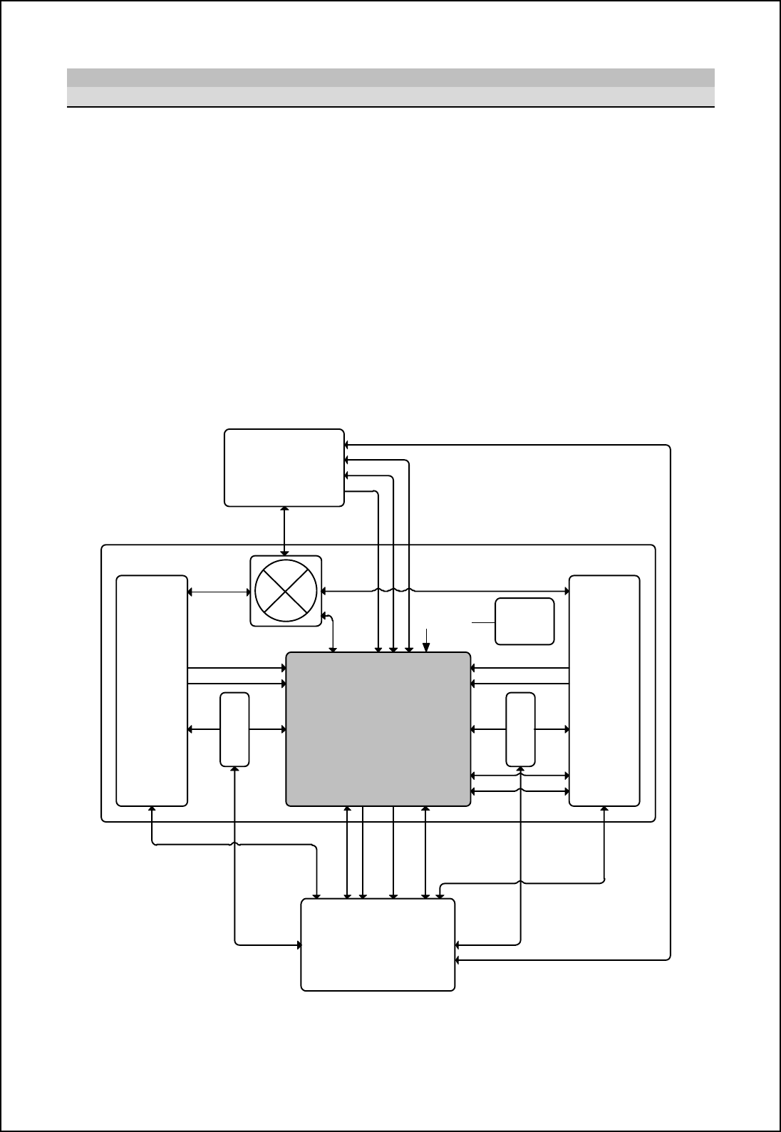
SBS-900 Shore Based Radar Systems
Chapter 10: Corrective maintenance
KH-1602-2 issue 1: Standard SBS900 Systems Operator & Maintenance Handbook
Page 153 of 240
10.7.8 SBS-A126 Switch Control & BITE PCA
10.7.8.1 Overview
The Switch control and BITE PCA system is a non-critical link in the system where one or two
SharpEyeTM transceivers are located within the same enclosure and share a single antenna sub-
system.
The role of the Switch control and BITE PCA is to:
'Derive power for the +5V advanced antenna sub-system ACP/ ARP encoder.
'Derive power for the +28V waveguide switch.
'Provide power to the +15V Standard antenna sub-system ACP/ ARP encoder.
'Monitor and digitally transmit voltage levels via RS422.
'Monitor system states and transmit via RS422 to the RDU.
'Monitor enclosure temperature using on-board sensor and transmit via RS422 to the RDU.
'Receive commands via RS422 and activate waveguide switch and polarisation switch.
'Ccmnlc\on_ Rcah[fm `lig nb_ @hn_hh[ _h]i^_l ni nb_ Rb[ljDs_x nl[hm]_cp_lm [h^ nb_ QCT-
'Clcp_ nb_ \f[hecha ionjonm `lig nb_ Rb[ljDs_x nl[hm]_cp_lm ni nb_ QCT-
'Allow throughput of video, sync and CAN signals to transceiver B.
Tx A Tx B
PSU
APSU
B
Switch control and BITE PCA
RDU
Antenna Sub-System
Switched Mains B
Fibre Control and Ststus
Control & Status
Motor On
Blanking Blanking
Motor On
Switched Mains A
RS422 / Blanking A+B
Oil Level and Temp Status
DC / ACP / ARP / Fail
Polarization control & status
DC Power
440V Motor Drive
DC PowerDC Power DC Power
Waveguide
Waveguide
Waveguide
Fibre Control and Status
ACP/ARP
CANBUS
CANBUS
Video & Sync
Vid & Sync
Optional
Cooling
Fans
RPM Data x6
Simplified Switch control and BITE PCA interconnection diagram
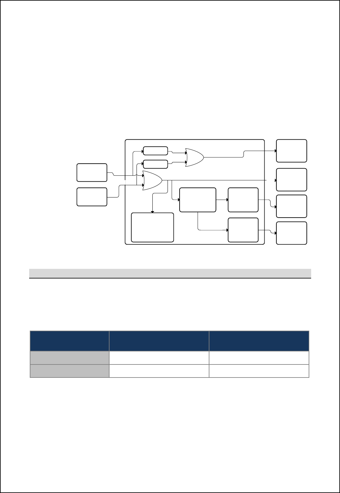
SBS-900 Shore Based Radar Systems
Chapter 10: Corrective maintenance
KH-1602-2 issue 1: Standard SBS900 Systems Operator & Maintenance Handbook
Page 154 of 240
PCA failure: If a failure of the Switch control and BITE PCA should occur then the default
transceiver (Tx A) will still be able to operate. Manual control of the waveguide switch,
and therefore Tx B, is still available.
Start-up: During start up, the waveguide switch is to be set to Tx A, and the polarisation switch
to horizontal. Once the communication between the PCA and the RDU has been
established and start-up checks are complete, then the processor takes over the
control of the waveguide and polarisation switches as commanded by the RDU.
Power: The PCA is powered by the 15VDC output of the power supply. When either PSU A
(single transceiver systems) or PSU B (dual transceiver systems) is powered, the
PCA is powered and operational.
On board DC-DC conversion provides all the power requirements of the PCA.
+15V
PSU A
+15V
PSU B
Control and BITE PCA
CHL Antenna
Encoder Power
Waveguide
Switch Driver
+15V
+15V
Board Power
Requirements
+5V
+28V (+0/-3V)
KH Antenna
Encoder Power
+15V
CHL Polarisation
Switch Driver
5V Stepdown
5V Stepdown
+28V DC-DC
Converter Polarisation
Switch
Waveguide
Switch
SBS-A126 PCA DC power schematic
10.7.8.2 Encoder DC power selection
Encoder power: The SBS-A126 PCA provides a DC power source for the ACP/ ARP encoder in the
antenna sub-assembly.
Link 8: Depending on the system installed, link 8 must be set to select the appropriate DC
output voltage.
SBS-A126 DC output Standard
antenna sub-systems Advanced
antenna sub-systems
Encoder power
SBS-A126: PL4 Pins 11 and 12 +15VDC +5VDC
Link 8 setting R_n ni •A jimcncih R_n ni •Bposition
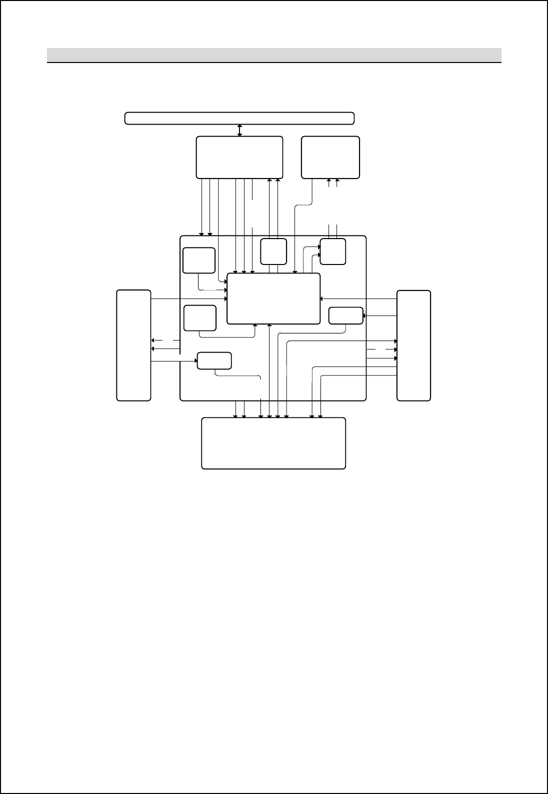
SBS-900 Shore Based Radar Systems
Chapter 10: Corrective maintenance
KH-1602-2 issue 1: Standard SBS900 Systems Operator & Maintenance Handbook
Page 155 of 240
10.7.8.3 Signal interfaces:
There are multiple interfaces for the Switch control and BITE PCA. The status of the various inputs is
monitored and transmitted to the RDU.
Control and
BITE PCA
Tx A Tx B
Turning Mechanism
CHL or KH Antenna
Encoder Fail
Processor
Oil Level
Oil Temp
Horizontal Polarisation
Waveguide Switch
Switch Position A
Switch Position B
Tellback
Driver
Motor OnMotor On
RDU
RS422
Differential
Driver
Differential
Driver
Blanking
Blanking
Blanking
Blanking Circular Polarisation
Driver
Polarisation Tellback
CAN
ACP
ARP
Video
Sync
ACP
ARP
Temperature
Sensor
Temp
ACP
ARP
ACP
ARP
Optional
Cooling
Fans
RPM Data x6
SBS-A126 signal interface schematic
Oil level: The oil level indicator monitors a normally closed voltage free contact. An open circuit
ch^c][n_m [ fiq icf `[ofn ]ih^cncih- Sbcm cm ihfs [p[cf[\f_ ih advanced antenna sub-
systems.
Oil temp: The oil temperature indicator monitors a normally closed voltage free contact. An
ij_h ]cl]ocn ch^c][n_m [h ip_l n_gj_l[nol_ `[ofn ]ih^cncih- Sbcm cm ihfs [p[cf[\f_ ih
advanced antenna sub-systems.
Encoder fail: The encoder on advance antenna sub-systems has a TTL (+5.0VDC) encoder fail
signal. @ l_]_cp_^ mcah[f i` z2.5V indicates normal operation, a signal of <0.5V
ch^c][n_m [h Dh]i^_l E[cf `[ofn ]ih^cncih-
Polarisation control: This is only available on advanced antenna sub-systems and controls the
status of the antenna polarisation. The default position is horizontal.
Polarisation tellback: The current polarisation position is fed to the PCA and reported to the RDU.

SBS-900 Shore Based Radar Systems
Chapter 10: Corrective maintenance
KH-1602-2 issue 1: Standard SBS900 Systems Operator & Maintenance Handbook
Page 156 of 240
Waveguide switch selector: (Dual transceiver systems only) Two +28V outputs provided for the
waveguide switch control. One output will cause the waveguide switch to set to
transmitter A, and the other sets the waveguide switch to transmitter B. The default
position is transceiver A. The selector switch defaults to the A position if there is a
fault in the communications to the PCA.
Waveguide switch tellback: (Dual transceiver systems only) The current position of the waveguide
switch is sensed and reported back to the RDU.
Motor on: Two motor ON signal inputs are monitored, one from each of the transceivers. Each
has a signal level of 15V DC when the motor is on, and 0V when the motor is off. The
status of the motor used to indicate which transceiver is running but does not control
the motor ON/ OFF function.
Blanking: Two blanking inputs are to be received by the card. A blanking input is received for
each transceiver via a 75SMB connection.
ACP/ARP: The Azimuth Clock Pulse (ACP) and Azimuth Reset Pulse (ARP) are distributed from
the encoder to both SharpEyeTM transceivers, the signals are also transmitted to the
RDU. The signals are not amplified and continue to operate in the event of a power
failure on the board.
Power fan sensing: Inputs receive, monitor and report the outputs (RPM) of the optional forced air
fans.
10.7.8.4 Indicators
LED Colour LED status
+15V Input A (input from PSU A) Green ON: +15V input ON
OFF: +15V input OFF
+15V Input B (input from PSU B) Green ON: +15V input ON
OFF: +15V input OFF
+15V (PCA power on) Green ON: +15V OK
OFF: +15V OFF
+5V (Generated on PCA) Green ON: +5V PSU OK
OFF: +5V PSU Off
+1.5V (Generated on PCA) Green ON: +1.5V PSU OK
OFF: +1.5V PSU Off
+28V (Generated on PCA) Green ON: +28V PSU OK
OFF: 28V PSU Off
Motor on Tx A Red ON: Motor On (Tx A)
OFF: Motor OFF
Motor on Tx B Red ON: Motor On (Tx B)
OFF: Motor OFF
Waveguide switch tellback position 2 x Red A ON: Waveguide switch in position A Waveguide B ON:
Waveguide switch in position B
Both OFF: Waveguide switch in transition position
Oil level Red ON: Oil level OK
OFF: Oil level low
Oil temp Red ON: Oil temp OK
OFF: Oil temp high
Encoder fail Red ON: Encoder OK
OFF: Encoder fail
Polarisation HP/VP tellback Bi-Colour RED ON: Waveguide switch in horizontal position
Green ON: Waveguide switch in vertical position
Both OFF:
Waveguide switch i
n transition position
Polarisation Circular tellback Bi-Colour Red ON: Waveguide switch in CW position
Green ON: Waveguide switch in ACW position
Both OFF: Waveguide switch in transition position
Optional Fan tellback Red ON: All fan speeds OK
OFF: One or more fan speed fail

SBS-900 Shore Based Radar Systems
Chapter 10: Corrective maintenance
KH-1602-2 issue 1: Standard SBS900 Systems Operator & Maintenance Handbook
Page 157 of 240
10.7.8.5 Test points
Test Point Description of test
+15V A +15V PSU A onto the PCA
+15V B +15V PSU B onto the PCA
+15V Board Derived +15V combined DC supply to PCA
+5V +5VDC
+28V +28VDC
+1.5V +1.5VDC
ACP UA0 Enable connection of an oscilloscope between its
differential inputs to
monitor waveform.
ACP UA1 Enable connection of an oscilloscope between its
differential inputs to monitor waveform.
ARP Enable connection of an oscilloscope between its
differential inputs to monitor waveform.
Motor on Test signal level input at the input to the board
Waveguide switch position A +28V
control Test +28V output to the waveguide switch actuator.
Waveguide switch position B +28V
control Test +28V output to the waveguide switch actuator.
Waveguide switch tellback position A Test continuity of waveguide switch tellback signal
between the tellback position A signal and the tellback
switch common signal connections.
Waveguide switch tellback position B Test continuity of waveguide switch tellback signal
between the tellback position B signal and the tellback
switch common signal connections.
Oil level Test continuity of oil level switch between the two oil
level signal connections.
Oil temp Test continuity of oil temp switch between the two oil
temp signal connections.
Encoder fail Test voltage input
Polarisation tellback A Test voltage input
Polarisation tellback B Test voltage input
Polarisation tellback C Test voltage input
Polarisation tellback D Test voltage input
Motor on Tx A Test signal voltage level at input, between +ve and ~ve
input.
Motor on Tx B Test signal voltage level at input, between +ve and ~ve
input.

SBS-900 Shore Based Radar Systems
Chapter 10: Corrective maintenance
KH-1602-2 issue 1: Standard SBS900 Systems Operator & Maintenance Handbook
Page 158 of 240
10.7.8.6 Links
Link function Ref
Position A
or
Open
Position B
or
Made
SETTING
Antenna Encoder Power
output LK8 15V 5V B
Polarity sw. A Pwr Option LK5 +28V switching supply
output External Supply A
Polarity sw. B Pwr Option LK6 +28V switching supply
output External Supply A
Polarity sw. C Pwr Option LK7 +28V switching supply
output External Supply A
Polarity Sw.A Tellback A opto
power option LK14 +15V pull up selected Active high external input A
Polarity Sw.A Tellback A opto
power option LK13 Active low input 0V A
Polarity Sw.A Tellback B opto
power option LK12 +15V pull up selected Active high external input A
Polarity Sw.A Tellback B opto
power option LK10 Active low input 0V A
Polarity Sw.B Tellback A opto
power option LK18 +15V pull up selected Active high external input A
Polarity Sw.B Tellback A opto
power option LK17 Active low input 0V A
Polarity Sw.B Tellback B opto
power option LK16 +15V pull up selected Active high external input A
Polarity Sw.B Tellback B opto
power option LK15 Active low input 0V A
Polarity Sw.C Tellback A opto
power option LK22 +15V pull up selected Active high external input A
Polarity Sw.C Tellback A opto
power option LK21 Active low input 0V A
Polarity Sw.C Tellback B opto
power option LK20 +15V pull up selected Active high external input A
Polarity Sw.C Tellback B opto
power option LK19 Active low input 0V A
RDU RS422 TX termination LK24 No Termination Termination Open
RDU RS422 RX termination LK25 No Termination Termination
Open
RDU Comms mode LK26 RS422 RS232
Open
Test Mode LK11 Normal Mode Test Mode
Open
Debug LK9 No Debug Debug Enabled Open
13V/36V BITE option LK23 13V 36V Open
Waveguide Sw. Tellback A
opto power option LK4 +15V pull up selected Active high external input A
Waveguide Sw. Tellback A
opto power option LK2 Active low input 0V A
Waveguide Sw. Tellback B
opto power option LK3 +15V pull up selected Active high external input A
Waveguide Sw. Tellback B
opto power option LK1 Active low input 0V A
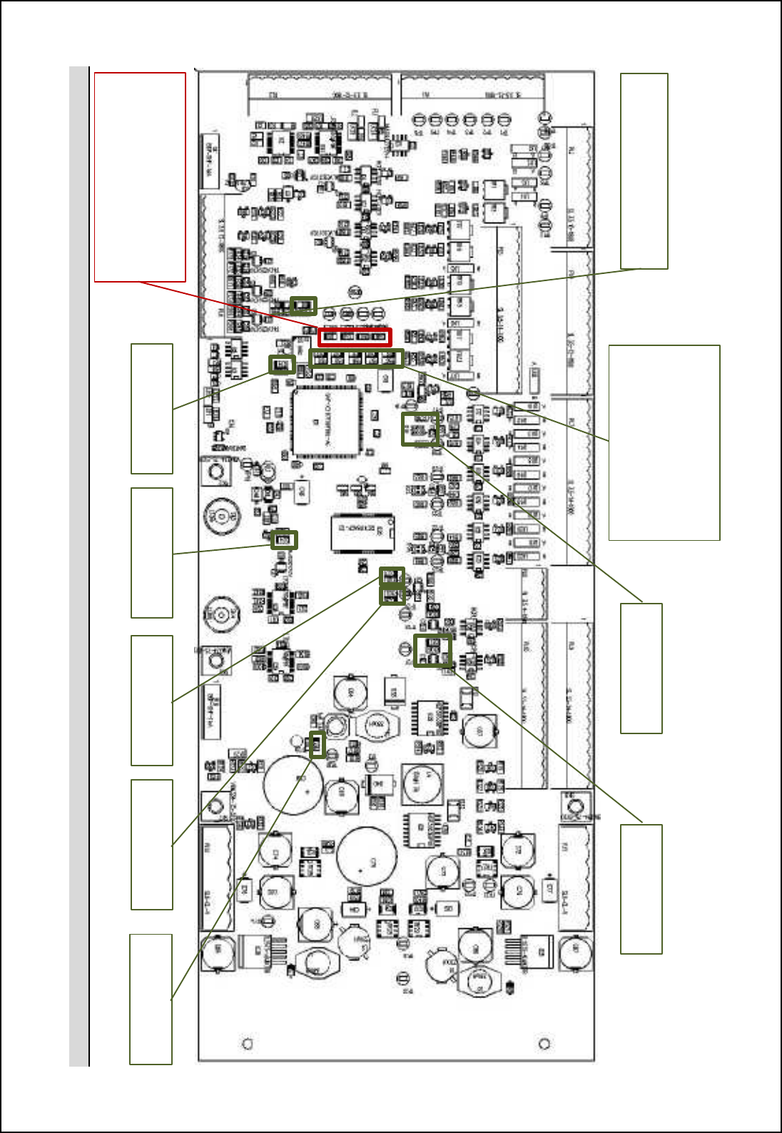
SBS-900 Shore Based Radar Systems
Chapter 10: Corrective maintenance
KH-1602-2 issue 1: Standard SBS900 Systems Operator & Maintenance Handbook
Page 159 of 240
10.7.8.7 PCA Layout
Green LED
3.3VDC
Green LED
1.5
VDC
Green LED
Fan OK
Red
LED
m 'nij ni \innig(
Waveguide Switch Position A
Waveguide Switch Position B
Fibre Switch Position A
Fibre Switch
Position B
Green LED (Flashing
PCA running
Green LED (top to bottom)
+5V OK
+15V_A OK
-15V_B OK
+15V_OK
+28V OK
Green LED
Tx A Motor ON
Green LED
Tx B Motor ON
Green LED
Oil Temp High
Green LED
Oil level Low
SBS-900 Shore Based Radar Systems
Chapter 10: Corrective maintenance
KH-1602-2 issue 1: Standard SBS900 Systems Operator & Maintenance Handbook
Page 160 of 240
PL1: Connection to RDU PL2: Serial & Blanking PL3: Waveguide Switch PL4: Antenna connections
PL1
-
1
Gnd
PL2
-
1
Gnd
PL3
-
1
Fibre position B tellback IN
PL4
-
1
nARP
PL
1
-
2
ACP1
PL2
-
2
Tx A blanking OUT
PL3
-
2
Fibre position A tellback IN
PL4
-
2
ARP
PL1
-
3
nACP1
PL2
-
3
Gnd
PL3
-
3
+5V fibre position B
PL4
-
3
Gnd
PL
1
-
4
Gnd
PL2
-
4
Gnd
PL3
-
4
Gnd
PL4
-
4
nACP2
PL1
-
5
ACP2
PL2
-
5
Tx B blanking OUT
PL3
-
5
WG position B tellback
PL4
-
5
ACP2
PL
1
-
6
nACP2
PL2
-
6
Gnd
PL3
-
6
WG position A tellback
PL4
-
6
Gnd
PL1
-
7
Gnd
PL2
-
7
Gnd
PL3
-
7
+V In WG
PL4
-
7
nACP1
PL
1
-
8
ARP
PL2
-
8
RS422 Tx+
PL3
-
8
+28V WG position A
PL4
-
8
ACP1
PL1
-
9
nARP
PL2
-
9
RS422 Tx
-
PL3
-
9
+28V WG position B
PL4
-
9
Gnd
PL
1
-
10
Gnd
PL2
-
10
Gnd
PL3
-
10
Gnd
PL4
-
10
Encoder Fail IN
PL1
-
11
Tx
B CAN+
PL2
-
11
RS422 Rx+
PL4
-
11
Encoder Power
PL1
-
12
TX
B CAN
-
PL2
-
12
RS422 Rx
-
PL4
-
12
Encoder Power
PL5: Ant. Polarisation PL6: Fans IN PL7: Tellback SK8: Tx A & B serial
PL5
-
1
Pol. AA
PL6
-
1
Gnd
PL7
-
1
Pol. Pair A pos. B
SK8
-
1
RxD A
PL
5
-
2
Pol. AB
PL6
-
2
FAN1 IN
PL7
-
2
+V IN pol. pair A
SK8
-
2
TxD A
PL
5
-
3
Ext Pol. DC A
PL6
-
3
FAN2 IN
PL7
-
3
Gnd
SK8
-
3
Gnd
PL5-4 Gnd PL6-4 FAN3 IN PL7-4 Pol. TB pair A pos. A SK8-4 RxD B
PL5
-
5
Gnd
PL6
-
5
FAN4 IN
PL7
-
5
Pol. TB pair B pos. B
SK8
-
5
TxD B
PL
5
-
6
Pol. BA
PL6
-
6
FAN5 IN
PL7
-
6
+V IN pol. pair B
SK8
-
6
Gnd
PL5
-
7
Pil. BB
PL6
-
7
FAN6 IN
PL7
-
7
Gnd
PL5
-
8
Ext Pol. DC B
PL6
-
8
Gnd
PL7
-
8
Pol. TB pair B pos. A
PL8:
BITE connection
PL5
-
9
Gnd
PL6
-
8
+12V Fans A
PL7
-
9
Pol. TB pair C pos
.
B
PL8
-
1
+3.3VDC
PL
5
-
10
Gnd
PL6
-
10
+12V Fans B
PL7
-
10
+V IN pol. Pair C
PL8
-
2
Gnd
PL
5
-
11
Pol. CA
PL6
-
11
Gnd
PL7
-
11
Gnd
PL8
-
3
Oil sensor switch
PL5
-
12
Pol. CB
PL6
-
12
Gnd
PL7
-
12
Pol. TB pair C pos. A
PL8
-
4
Gnd
PL
5
-
13
Ext Pol. DC C
PL7
-
13
Gnd
PL5
-
14
Gnd
PL7
-
14
+28VDC

SBS-900 Shore Based Radar Systems
Chapter 10: Corrective maintenance
KH-1602-2 issue 1: Standard SBS900 Systems Operator & Maintenance Handbook
Page 161 of 240
PL9: TX A connection PL10: TX B connection PL11: PSU A PL12: PSU B
PL9
-
1
ACP1
PL9
-
1
ACP1
PL11
-
1
Gnd
PL12
-
1
Gnd
PL
9
-
2
nACP1
PL9
-
2
nACP1
PL11
-
2
+15VDC
PL12
-
2
+15VDC
PL9
-
3
Gnd
PL9
-
3
Gnd
PL11
-
3
Gnd
PL12
-
3
Gnd
PL
9
-
4
ACP2
PL9
-
4
ACP2
PL11
-
4
+3.3VDC
PL12
-
4
+3.3VDC
PL9
-
5
nACP2
PL9
-
5
nACP2
PL11
-
5
Gnd
PL12
-
5
Gnd
PL
9
-
6
Gnd
PL9
-
6
Gnd
PL11
-
6
+13VDC
PL12
-
6
+13VDC/ +36VDC
PL9
-
7
ARP
PL9
-
7
ARP
PL9
-
8
nARP
PL9
-
8
nARP
PL9
-
9
Gnd
PL9
-
9
Gnd
PL9
-
10
Tx A Mon +
PL9
-
10
Tx B Mon +
PL9
-
11
Tx A Mon
-
PL9
-
11
Tx B Mon
-
PL9
-
12
Gnd
PL9
-
12
Gnd
PL9
-
13
N/C
PL9
-
13
Tx B CAN +
PL9
-
14
N/C
PL9
-
14
Tx B CAN
-

SBS-900 Shore Based Radar Systems
Chapter 10: Corrective maintenance
KH-1602-2 issue 1: Standard SBS900 Systems Operator & Maintenance Handbook
Page 162 of 240
Page internationally blank

SBS-900 Shore Based Radar Systems
Chapter 10: Corrective maintenance
KH-1602-2 issue 1: Standard SBS900 Systems Operator & Maintenance Handbook
Page 163 of 240
10.7.9 SharpEyenerror messages
If a fault condition is detected within the SharpEyeTM transceiver, a fault message is sent to the Radar
Distribution Unit and in certain conditions the unit switches to a degraded low power state of
operation.
The following is a list of possible alarm conditions that can occur within the SharpEye transceiver.
SharpEye
TM
error Message Description
Rx sensitivity If the minimum detectable signal rises above a pre-set level the transceiver
sends a receiver sensitivity warning message.
VSWR
If the VSWR on the RF output is worse than 1.4:1 the transceiver sends an
antenna VSWR warning message and switches to the degraded fiq jiq_l
state of operation.
If the VSWR on the RF output is worse than 2.0:1 the transceiver enters fault
mode and is shutdown.
SYNTH The synthesiser has not initialised correctly; cycling the power may clear this
condition (emergency stop).
Tx power
If the RF output power falls below 100W the transceiver sends an RF Power
LOW warning message and switches to the degraded fiq jiq_l state of
operation.
Over temperature
If the temperature of the RF power transistors in the transceiver exceeds a
jl_^_n_lgch_^ fcgcn+ nb_ nl[hm]_cp_l m_h^m [h •ip_l-n_gj_l[nol_ q[lhcha ni nb_
Radar Distribution Unit and switches to the degraded fiq jiq_l state.
If the temperature exceeds a further pre-set limit the transceiver switches to
the fault state and transmission is stopped.
As the temperature returns to within the predetermined limits, the transceiver
returns to the degraded state and then to normal transmit operation.
Turning info lost
If the antenna stops rotating when not commanded to stop, a warning
message is sent to the display equipment and the transceiver switches to the
fault state and transmission is stopped.
ARP/HL not
detected
If an azimuth or heading line pulse is not detected, a message is sent to the
transceiver and for safety reasons transmission is stopped within 60 seconds.
Azimuth status
(1)
Antenna rotation is checked for clockwise rotation (viewed from above). If anti-
clockwise rotation is detected, a message is sent and transmission is stopped
within 60 seconds.
Azimuth status
(2)
If missing pulses between heading lines are detected, a message is sent and
transmission is stopped within 60 seconds.
SBS-900 Shore Based Radar Systems
Chapter 10: Corrective maintenance
KH-1602-2 issue 1: Standard SBS900 Systems Operator & Maintenance Handbook
Page 164 of 240
SharpEye
TM
error Message Description
FPGA2 failed If the transceiver detects a hardware fault, it sends a warning message to the
display equipment and switches to the Degraded state of operation.
Degraded
(Low power)
The transceiver continuously runs background performance checks on forward
power, reverse power, receiver sensitivity and temperature. If any of these
parameters falls outside predetermined levels a warning message is sent to
the Radar Distribution Unit indicating the nature of the fault.
The transceiver continues to operate, but with reduced performance and
functionality.
Caution: As a result of reduced output power, range performance will be
reduced and the system may not meet the expected operational detection
performance.
Fault
If the performance or functionality is degraded such that the transceiver cannot
operate it enters the fault state and a fault message is sent to the display
equipment.
The transceiver stops radiating RF and there is no video output to the Radar
Distribution Unit.
A spurious fault may be cleared by re-powering the equipment.
Communication
error
If communication is lost between the Radar Distribution Unit and the
SharpEyeTM, the RDU reboots the SharpEye leading to a potential 60 second
gap in coverage.
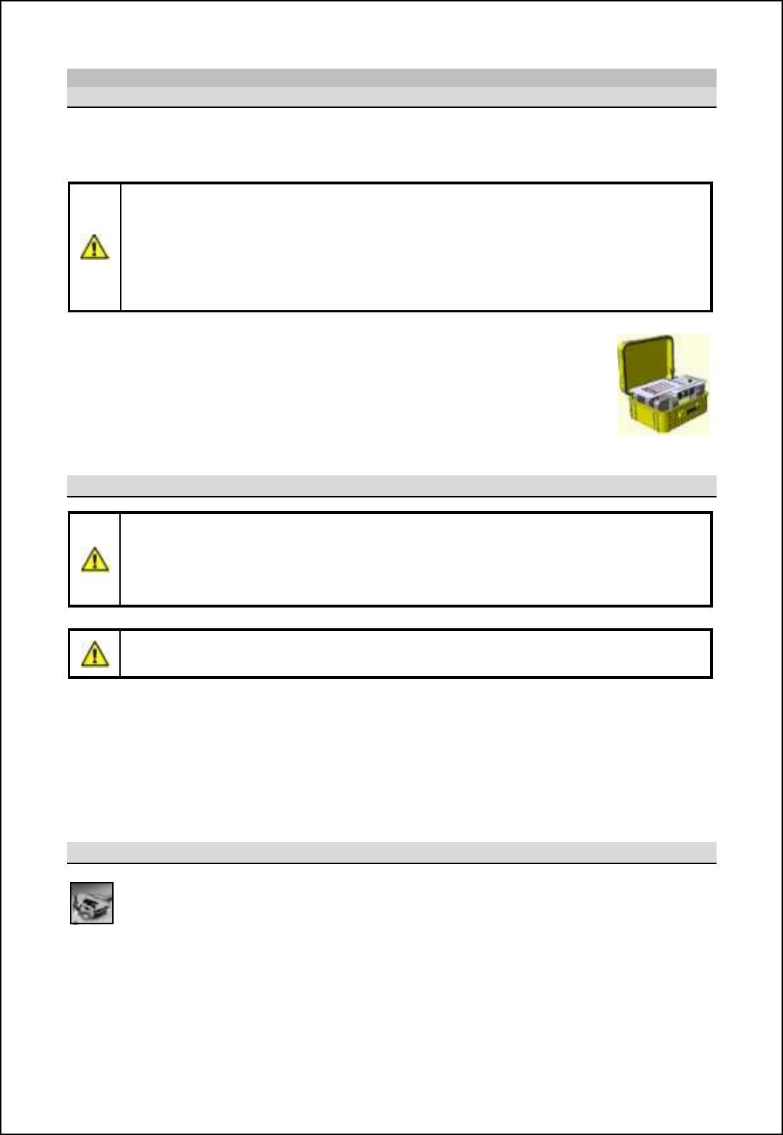
SBS-900 Shore Based Radar Systems
Chapter 10: Corrective maintenance
KH-1602-2 issue 1: Standard SBS900 Systems Operator & Maintenance Handbook
Page 165 of 240
10.7.10 X-band transceiver processor
10.7.10.1 Overview
Sb_ mifc^ mn[n_ Rb[ljDs_x nl[hm]_cp_l(s) are secured inside the transceiver enclosure and are
controlled by the Radar Distribution Unit.
SharpEye processor gsealed unit:
'The SharpEyeTM processor uses solid state components and has no 'lifed' items.
'The unit has no field serviceable or repairable parts and must be returned to the
manufacturer for repair.
'The processor must never be dismantled as it is a sealed unit that contains beryllium
(see health and safety notices in section 2).
Spares kits: Where a SharpEye
TM
processor is supplied as a spare, it is shipped in
a kit form that includes:
- A spare processor
- A ruggedised delivery case that must be used for returning the removed
processor
-
I
nstructions
on returning the removed unit
Precautions
HEAVY ITEM: The SharpEyeTM transceiver is a heavy item. Care should be exercised
when removing and moving the processor.
HOT SURFACES: If the SharpEyeTM has been in operation or the transceiver enclosure
has been exposed to strong sunlight, the processor unit will be hot to the touch.
Do not operate the SharpEyeTM system with the waveguide or antenna disconnected.
No. of people: Due to the weight of the processor and depending on the level of access to
the transceiver Enclosure, it is recommended that changing the processor is
carried out by two people.
Health & Safety: All health and safety notices shown in section 2 must be observed at all times
including those regarding working aloft.
Tools
Tools: In addition to the normal tools required for service work, the following tools will be
required to carry out this replacement.
- 4BA open ended spanner
- 5.0mm Allen key (recommended 150mm long)
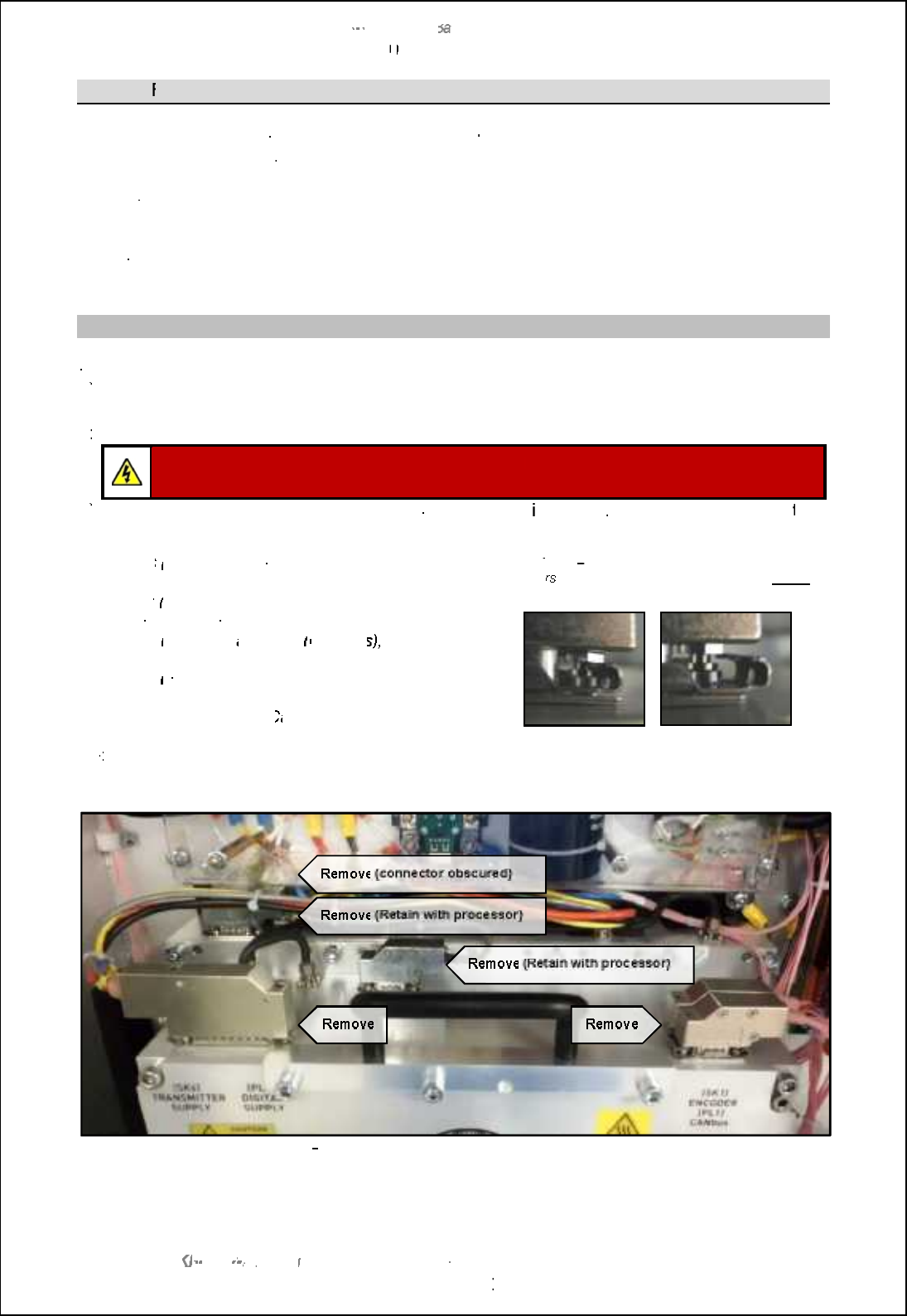
SBS
-
900 Shore
Ba
Ba
sed
Radar Systems
Chapter
10
10
:
Corrective maintenance
KH
KH
-
1602 2
issue 1
:
Standard SBS900 Systems Operator & Maintenance Handbook
Page
166
of
240
10.7.10.2
R
emoval & replacement
The following process shows the removal of a single X
-
@?LB6F?PN( WC\ NPMACQQMP
located in the
left
hand side of the enclosure
.
The removal and replacement processes are
exactly the
same for the
removal of the
right hand
processor
Prior to undertaking this task, maintainers should familiarise themselves with the processes detailed
below
.
Removal
a)
a)
Fully isolate the entire system
from all power sources including any UPS services.
b)
b)
As a safety precaution, switch OFF the AC mains breaker(s) located within the transceiver
enclosure.
c)
c)
To improve access, remove and retain the clear cover over the power supply unit.
CAUTION:
When AC power is removed,
residual
DC
voltages will be present for a short
period on the terminals of the capacitors within the power supply unit
d)
d)
Noting the positions, orientation and connector numbers, d
isconnect
ALL
internal
connections
to
the
Rb[ljDs_x
processor as detailed below:
-
SK6
(transmitter power), located on the top left
hand side of the unit.
-
PL2
(digital supply), also located on the top left
hand side of the unit.
-
SK1
(encoder)
and
PL1
(
CANBus
)
, located on
the top right hand side of the unit.
-
SK5
(Blanking), located on the right hand side of
the unit.
-
Fibre Optic cable:
C
arefully note the positions
of each cable and gently remove.
Note:
The D
type connectors have sliding metal
retainer
which must be moved fully one way
before
the connector can be removed.
Locked
Unlocked
e)
e)
Interconnections:
There are two interconnecting connectors
on the top of the processor which
can be removed to improve access. These must be replaced and returned with the processor.
X
band
6F?PN( WC\ NPMACQQMPQFMUGLEAMLLCARMPQ
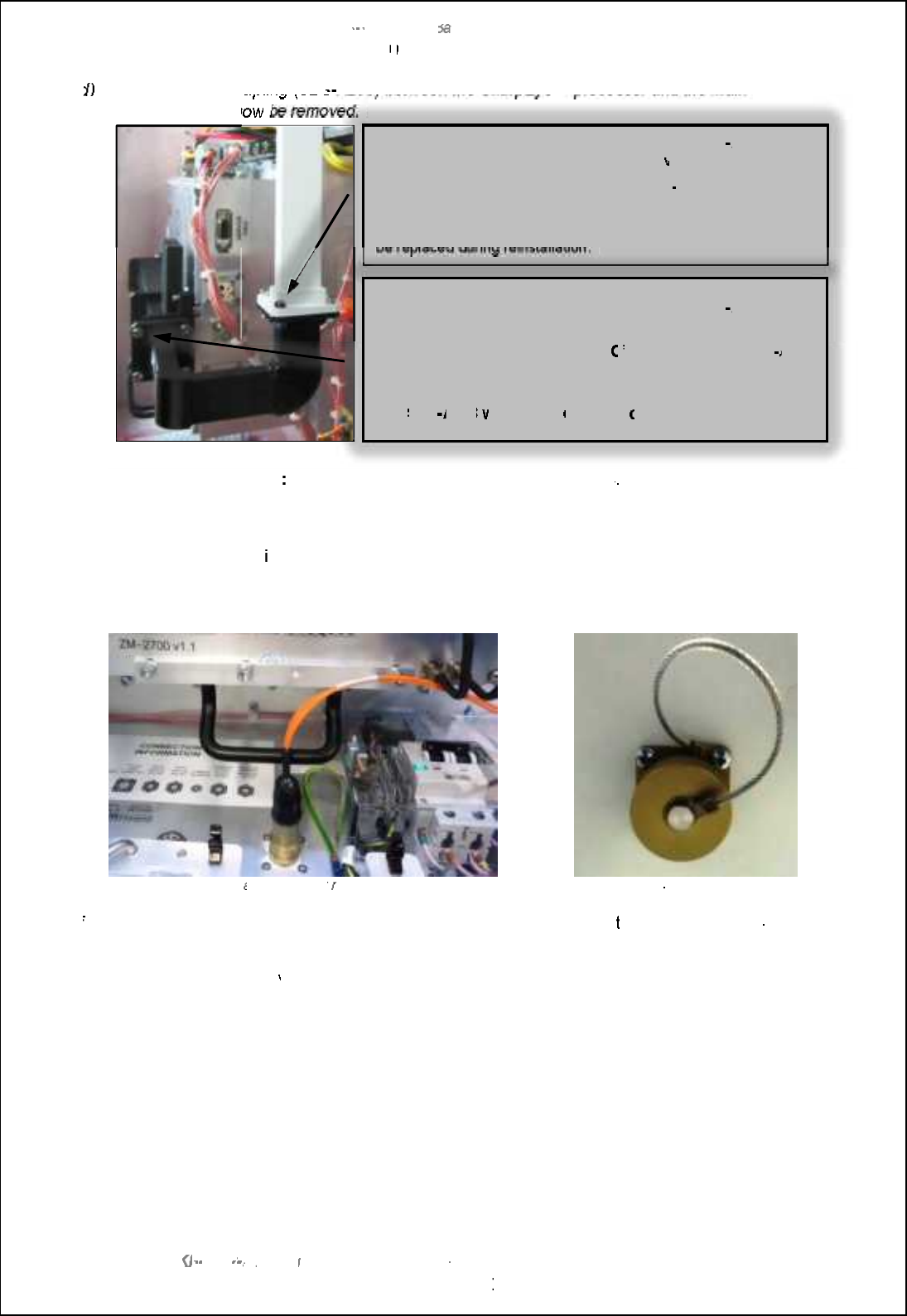
SBS
-
900 Shore
Ba
Ba
sed
Radar Systems
Chapter
10
10
:
Corrective maintenance
KH
KH
-
1602 2
issue 1
:
Standard SBS900 Systems Operator & Maintenance Handbook
Page
167
of
240
d)
d)
The waveguide coupling (SBS
-
9 <KN<<EK?<0 ?8 IG$P<S GIF: <JJFI8 E;K?<D 8 @E
waveguide
must now
be removed.
e)
e)
Fibre Optic connector
The fibre optic connector can restrict access
. To prevent damage to this
connector and the cables, it is recommended that the connector is carefully unscrewed from the
chassis and gently lowered out of the way.
The connector is reta
ined into the chassis by 4
cross head bolts accessed from the base of the
enclosure.
The connector also has a waterproof seal that should be carefully retain as it MUST be replaced.
Fibre cable
and connector
restricting access
Detail of fibre
connector on base of enclosure
f)
f)
Static Desiccator:
If required, the static desiccator
can be removed
to improve access.
The
desiccator
assembly can be removed by unscrewing the retaining ring within the enclosure.
The unit is fitted
with a
waterproof seal that should be carefully
retained
as it MUST be replaced.
Remove and retain the 4 x 4BA bolts that fix the SBS
A203
waveguide coupling to the main waveguide
within the enclosure
There is a waveguide shim between the SBS
-
A203 and the
waveguide.
Note its position and orientation, remove and retain this as it must
be replaced during reinstallation.
Remove and retain the 4 x 4BA bolts that fix the SBS
A203
waveguide coupling to the SharpEye waveguide interconnection.
7FCPCGQ?U?TCESGBCQFGK ?LB?Le
O
fPGLE@CRUCCLRFC6 %6
A203
and the SharpEye waveguide interconnection, remove and retain
these.
The
SBS
A203
waveguide
coupling
can now be removed.
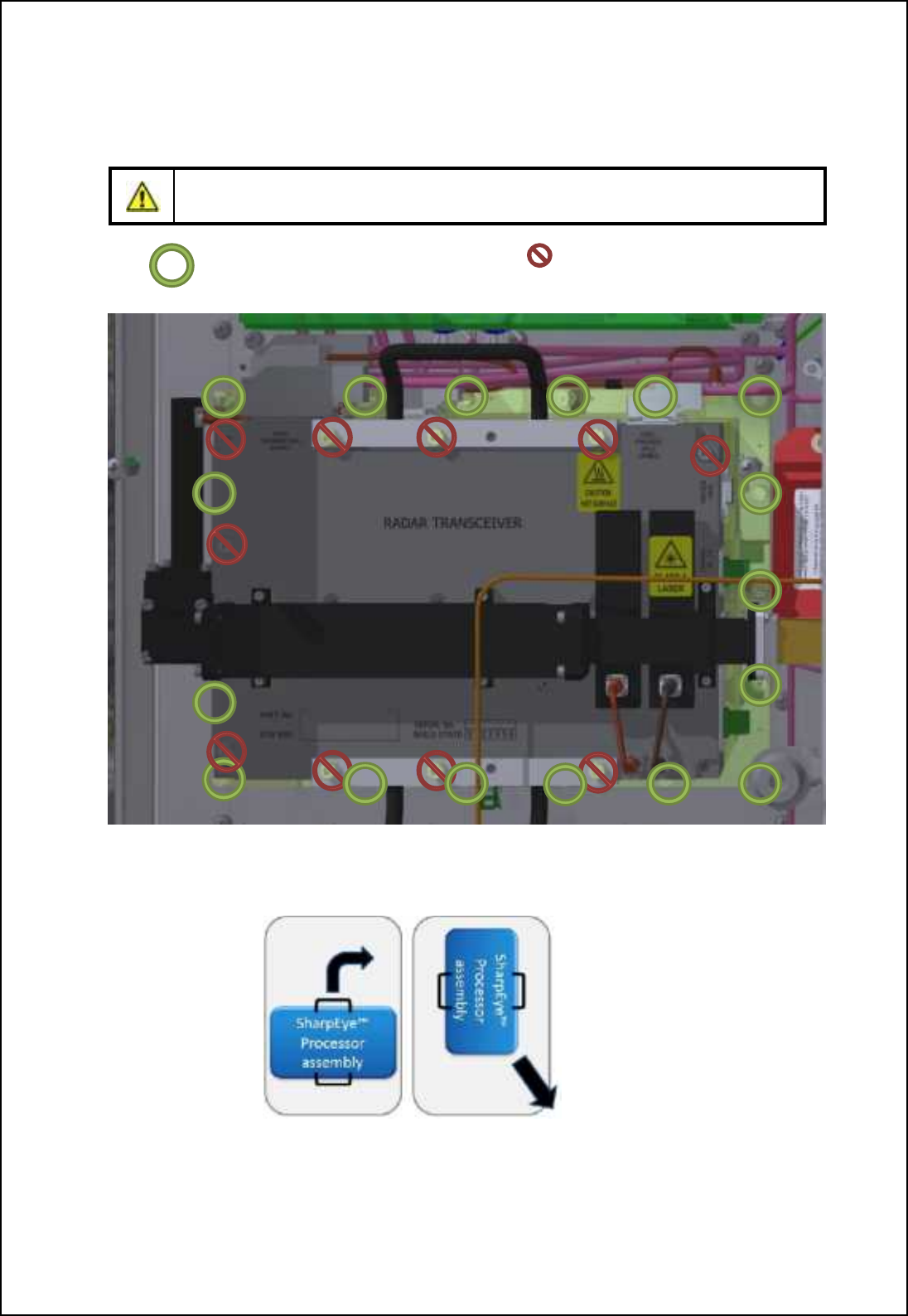
SBS-900 Shore Based Radar Systems
Chapter 10: Corrective maintenance
KH-1602-2 issue 1: Standard SBS900 Systems Operator & Maintenance Handbook
Page 168 of 240
g) Processor removal: The SharpEyeTM processor is retained into the Enclosure by 17 x 5mm hex
bolts. These should be removed, retained and the processor carefully lifted from the assembly
using the carrying handles.
Caution: Sb_ \ifnm ih nb_ Rb[ljDs_x jli]_mmil cnm_f` LTRS MNS AD QDLNUDC;
removal of these bolts invalidates the warranty status of the unit (see below).
Bolts to be removed DO NOT remove
Note: Some of the bolts circled below are obscured in the drawing.
X-=TaW L[Tec@lXo JebVXffbe
Removal hint: Rotating the processor by 90 degrees makes it easier to remove the unit from
the processor.
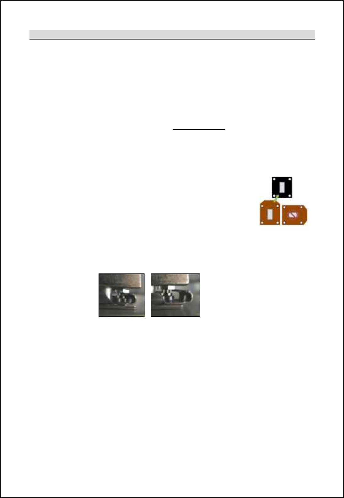
SBS-900 Shore Based Radar Systems
Chapter 10: Corrective maintenance
KH-1602-2 issue 1: Standard SBS900 Systems Operator & Maintenance Handbook
Page 169 of 240
Processor replacement
Replacement: The processor is replaced by reversing the removal procedure.
Supporting lugs: The processor can be temporarily rested on two logs inserted into the
backplate of the enclosure. This helps to support and align the processor
during the replacement processes but does not secure the unit into place.
Caution: As noted in the previous section, the processor is a heavy item;
care should be exercised when replacing the unit.
Retaining bolts: Replace the 17 retaining bolts and washers removed earlier in the removal
process. ALL 17 fasteners MUST be replaced.
Caution: The bolts ensure that a full thermal bond is achieved between the
processor and the heatsink in the enclosure. Failure to replace a bolt
increases the possibility of a poor bond leading to L[Tec@lXo cebVXffbe
overheating issues.
Waveguide: Replace the waveguide joiner removed earlier between
nb_ Rb[ljDs_x jli]_mmil [h^ nb_ g[ch q[p_aoc^_- @ff
nuts, bolts, washers and waveguide shims/ O-rings
must be replaced.
Pay particular attention to the orientation of the
waveguide shim.
Connectors: Reconnect all connectors.
The D-type connectors have sliding metal retainers which must be moved
fully one way to lock the connector into position
Locked Unlocked
Re-Y\go7 Where removed to improve access, refit the following:
- The fibre Optic cable/ connector
- Static desiccator
- Clear power supply protection cover.
Unit inspection: Prior to restoring AC power to the system carry out the following checks:
- All fasteners are securely tightened.
- All connectors are securely fitted in the correct positions.
- All RF (Waveguide) couplings are securely and correctly fitted and
tightened.
Test: When th_ Rb[ljDs_x jli]_mmil b[m \__h mo]]_mm`offs l_-fitted, apply AC
power to the system and test.

SBS-900 Shore Based Radar Systems
Chapter 10: Corrective maintenance
KH-1602-2 issue 1: Standard SBS900 Systems Operator & Maintenance Handbook
Page 170 of 240
Part and serial number log:
Use the following form to log the part and serial numbers of the removed and replacement unit:
The details required below can be found on the front of the SharpEye processor.
Replacement unit fitted:
Part Number
S/W VER. (software version)
Serial No.
Build State
Replacement date (dd / mm / yyyy)
Unit return
The SharpEyeTM processor is a sealed unit that must be returned to Kelvin Hughes for repair or in line
with RoHS requirements, for safe disposal when the equipment has reached the end of its serviceable
life.
The removed unit must be returned to Kelvin Hughes Ltd in the ruggedised case supplied with the kit.
Warranty Seals
The breaking of any warranty seals invalidates the warranty status of the unit.
Removed unit to be returned:
Part Number
S/W VER. (software version)
Serial No.
Build State
Replacement date (dd / mm / yyyy)

SBS-900 Shore Based Radar Systems
Chapter 10: Corrective maintenance
KH-1602-2 issue 1: Standard SBS900 Systems Operator & Maintenance Handbook
Page 171 of 240
10.7.11 S-band Transceiver processor
10.7.11.1 Overview
Sb_ mifc^ mn[n_ Rb[ljDs_x nl[hm]_cp_l is secured into the right hand side of the transceiver
enclosure and is controlled by the Radar Distribution Unit.
SharpEye processor gsealed unit:
'The SharpEyeTM processor uses solid state components and has no 'lifed' items.
'The unit has no field serviceable or repairable parts and must be returned to the
manufacturer for repair.
'The processor must never be dismantled as it is a sealed unit that contains beryllium
(see health and safety notices in section 2).
Spares kits: Where a SharpEye
TM
processor is supplied as a spare, it is shipped in
a kit form that includes:
- A spare processor
- Full removal and installation instructions
- A ruggedised delivery case that must be used for returning the removed
processor
Precautions
HEAVY ITEM: The SharpEyeTM transceiver weighs approximately 15Kg. Care should be
exercised when removing and moving the processor.
HOT SURFACES: If the SharpEyeTM has been in operation or the transceiver enclosure
has been exposed to strong sunlight, the processor unit will be hot to the touch.
Do not operate the SharpEyeTM system with the waveguide or antenna disconnected.
No. of people: Due to the weight of the processor and depending on the level of access to
the transceiver Enclosure, it is recommended that changing the processor is
carried out by two people.
Health & Safety: All health and safety notices shown in section 2 must be observed at all times
including those regarding working aloft.
Tools
Tools: In addition to the normal tools required for service work, the following tools will be
required to carry out this replacement.
- 4BA open ended spanner
- 5.0mm Allen key (recommended 150mm long)
SBS-900 Shore Based Radar Systems
Chapter 10: Corrective maintenance
KH-1602-2 issue 1: Standard SBS900 Systems Operator & Maintenance Handbook
Page 172 of 240
10.7.11.2 S band processor removal & replacement
The following process shows the removal of a single S-\[h^ Rb[ljDs_x processor located in the
right hand side of the enclosure.
Prior to undertaking this task, maintainers should familiarise themselves with the processes detailed
below.
Removal
The removal process is identical to the X-band processor removal shown in the previous
section. Please refer this section for instructions.
RF coupling: The only difference between the X-band and S-band removal is the RF coupling. In
the S-band system the waveguide is replaced by a semi-rigid RF coupling.
Replacement
Replacing the S-band SharpEye processor is carried out using the replacement processes described
in the X-band section.
The only difference between the X-band and S-band removal is the RF coupling. In the S-band
system the waveguide is replaced by a semi-rigid RF coupling.
Refitting the semi-rigid RF cable: When refitting the cable, ensure you observe the handling
precautions noted below.
- The nut on the semi-rigid RF cable should be tightened to 1.0Nm.
-H` hi nilko_ ql_h]b cm [p[cf[\f_ nb_ `[mn_hcham mbiof^ \_ a_hnfs ncabn_h ni •finger tight-
- DO NOT over tighten as this can deform and damage the cable.
Semi-rigid coaxial cable handling precautions:
- Take care when removing and re-installing the coaxial cable.
- The rigid coaxial cable must not be bent, crushed, deformed or damaged in any way.
- If the cable is accidently damaged, it must be replaced.
-Damage to this cable can reduce the transceiver performance or in the worst case stop
transmission.
SBS-900 Shore Based Radar Systems
Chapter 10: Corrective maintenance
KH-1602-2 issue 1: Standard SBS900 Systems Operator & Maintenance Handbook
Page 173 of 240
Part and serial number log:
Use the following form to log the part and serial numbers of the removed and replacement unit:
The details required below can be found on the front of the SharpEye processor.
Replacement unit fitted:
Part Number
S/W VER. (software version)
Serial No.
Build State
Replacement date (dd / mm / yyyy)
Unit return
The SharpEyeTM processor is a sealed unit that must be returned to Kelvin Hughes for repair or in line
with RoHS requirements, for safe disposal when the equipment has reached the end of its serviceable
life.
The removed unit must be returned to Kelvin Hughes Ltd in the ruggedised case supplied with the kit.
Warranty Seals
The breaking of any warranty seals invalidates the warranty status of the unit.
Removed unit to be returned:
Part Number
S/W VER. (software version)
Serial No.
Build State
Replacement date (dd / mm / yyyy)
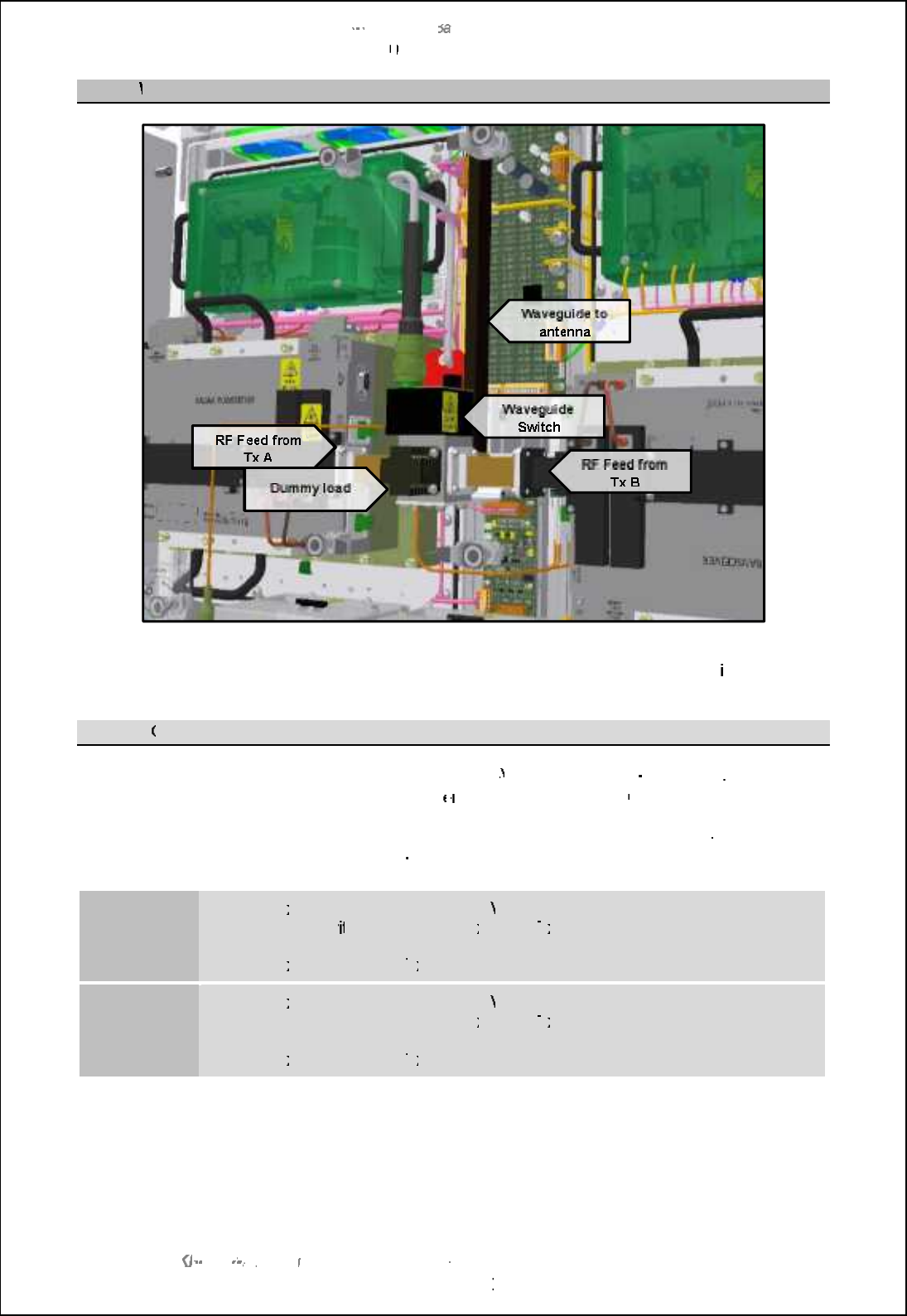
SBS
-
900 Shore
Ba
Ba
sed
Radar Systems
Chapter
10
10
:
Corrective maintenance
KH
KH
-
1602 2
issue 1
:
Standard SBS900 Systems Operator & Maintenance Handbook
Page
174
of
240
10.7.12
Waveguide switch
Waveguide switch
assembly
The RF outputs of Tx
A and Tx B are connected to the antenna via a waveguide switch
internally
mounted in the centre of the transceiver enclosure.
10.7.12.1
Operation
Power:
The waveguide switch operates from
+28
VDC from
the SBS
-
A126 PCA
. This supply
is available as soon as the transc
e
iver enclosure switches
ON.
Control:
During Local or Remote operation, the waveguide switch is controlled by the Radar
Distribution Unit via the SBS
-
A126 PCA and requires no operator input.
Tx A selected
-
The
Tx
Tx
A select line will be
at +28
VDC
-
When the sw
itch has selected
Tx
Tx
A, the
Tx
Tx
(A) SEL tell back line goes
Hi
confirming that the switchover has been successful.
-
The
Tx
Tx
(B) select and
Tx
Tx
(B) tell back lines are both at zero volts.
Tx B selected
-
The
Tx
Tx
B select line will be
at +28
VDC
-
When the switch has selected
Tx
Tx
B, the
Tx
Tx
(B) SEL tell back line goes
Hi
confirming that the switchover has been successful.
-
The
Tx
Tx
(A) select and
Tx
Tx
(A) tell back lines are both at zero volts.
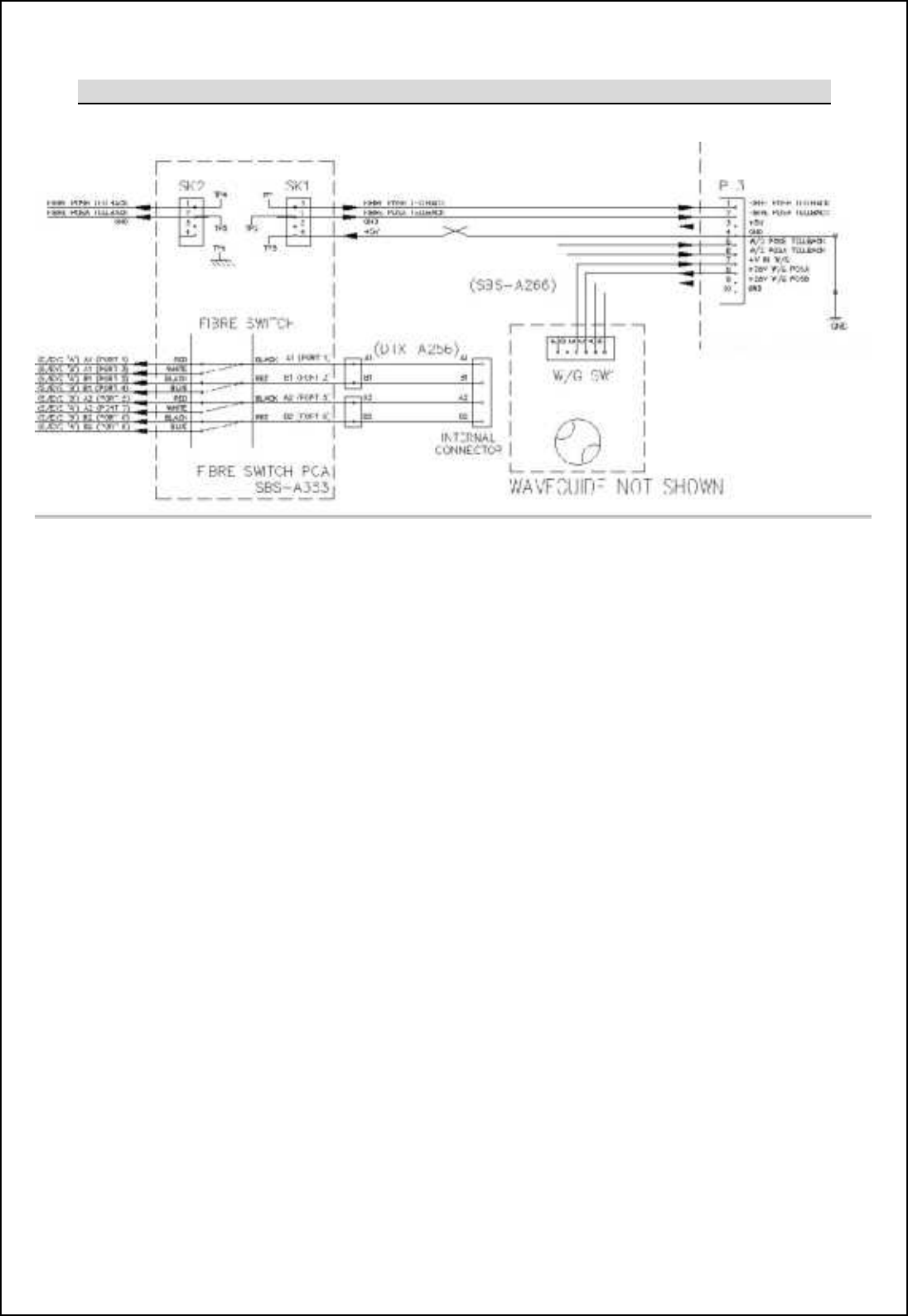
SBS-900 Shore Based Radar Systems
Chapter 10: Corrective maintenance
KH-1602-2 issue 1: Standard SBS900 Systems Operator & Maintenance Handbook
Page 175 of 240
10.7.12.2 Schematic
Extract from Transceiver system diagram reference DTX-C7
If there is a fault condition that prevents the waveguide switch selecting a transceiver, the RDU will
make 10 attempts at reselecting the switch. After the 10thattempt the system reverts to the original
transceiver and the RDU will display an alarm stating Waveguide Switch Fail.
In this condition and providing the waveguide switch is not jammed is possible to manually change the
position of the waveguide switch using the rotary control on the top of the switch.
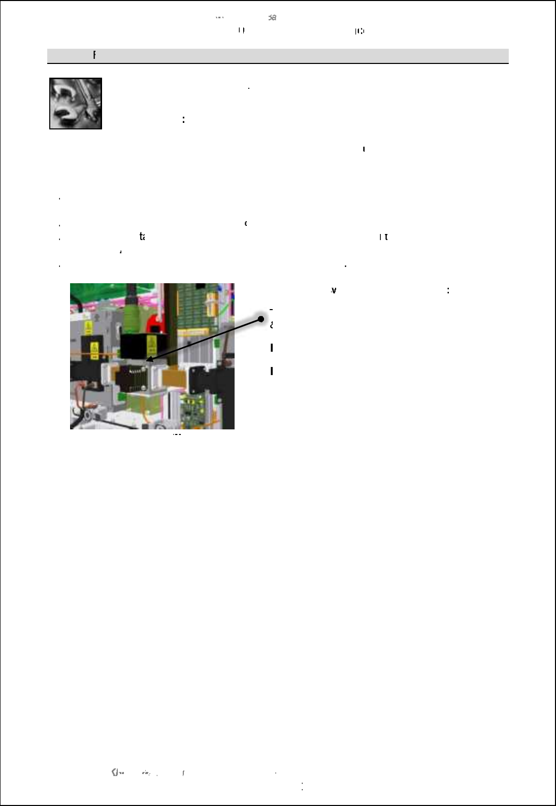
SBS
-
900 Shore
Ba
Ba
sed
Radar Systems
Chapter
10
10
:
Corrective maintenan
ce
ce
KH
KH
-
1602 2
issue 1
:
Standard SBS900 Systems Operator & Maintenance Handbook
Page
176
of
240
10.7.12.3
Removal & replacement
Tools:
In addition to the normal tools required for service and maintenance work, the
following tools will be required:
4BA spanner
:
Used for the removal of the waveguide bolts.
The waveguide switch cannot be repaired in the field and contains no
user accessible parts.
Removal:
The waveguide switch is removed as follows:
1.
1.
Fully isolate and disconnect the system from all sources of AC power including any UPS
supported mains.
2.
2.
Disconnect the connector from the
top
of the waveguide switch.
3.
3.
Remove and re
tain all nuts, bolts and washers that retain the switch
in
in
to the
transceiver
enclosure.
All fastenings must be retained as they will be required for refitting.
4.
4.
Once the fastenings are removed the switch can be removed
Waveguide switch on SBS
-
A125
chassis
Waveguide s
witch port identification
:
The ports are identified by numbered labels (1, 2, 3
&4) attached to the main switch.
Port 1:
RF feed for antenna
Port 2:
RF feed for transceiver B
Port 3:
dummy Load
Port 4:
RF feed for transceiver A
Refitting:
To refit the waveguide switch, reverse the above removal process making a carful note of
the port locations on the switch noted above.
RF seal:
Ensure that all RF couples are correctly aligned and tightened. Incorrectly terminated
RF couplings
can lead to RF leakage which can be hazardous to health and cause
system performance issues.
Caution:
When reinstalling the switch take extreme care when fitting and tightening the bolts
into the switch assembly as it is easy to cross thread or break the
bolts.
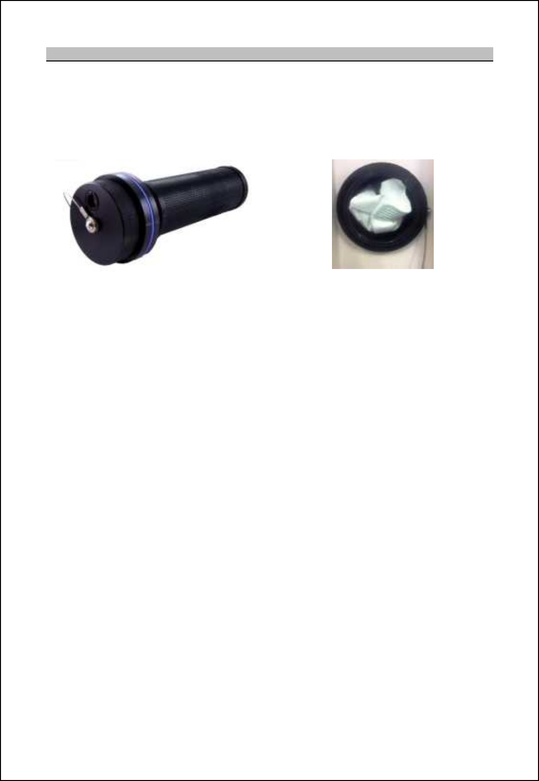
SBS-900 Shore Based Radar Systems
Chapter 10: Corrective maintenance
KH-1602-2 issue 1: Standard SBS900 Systems Operator & Maintenance Handbook
Page 177 of 240
10.7.13 Static desiccator
The DTX-A7 Transceiver Enclosure is fitted with a static desiccator. With the exception of changing
the two desiccant packets contained within the unit, the desiccator assembly requires no
maintenance.
The desiccator is accessed externally on the base of the Enclosure or on earlier units is located
between the two access doors on the front of the enclosure.
Example of desiccato
r
Example of desiccator with cover removed
The unit contains two desiccant sachets which must be changed annually (see Annual Planned
Maintenance section 9.4 pages 88 onwards).
When removing and replacing the desiccant sachets care should exercised to ensure that the packets
are not torn or split. Split or damaged sachets must not be used.
Spares part number
Replacement sachet: 55-100-0494-002
Sachet shelf life: 2-years
Note: The part number noted above is for 1 sachet, two are required.
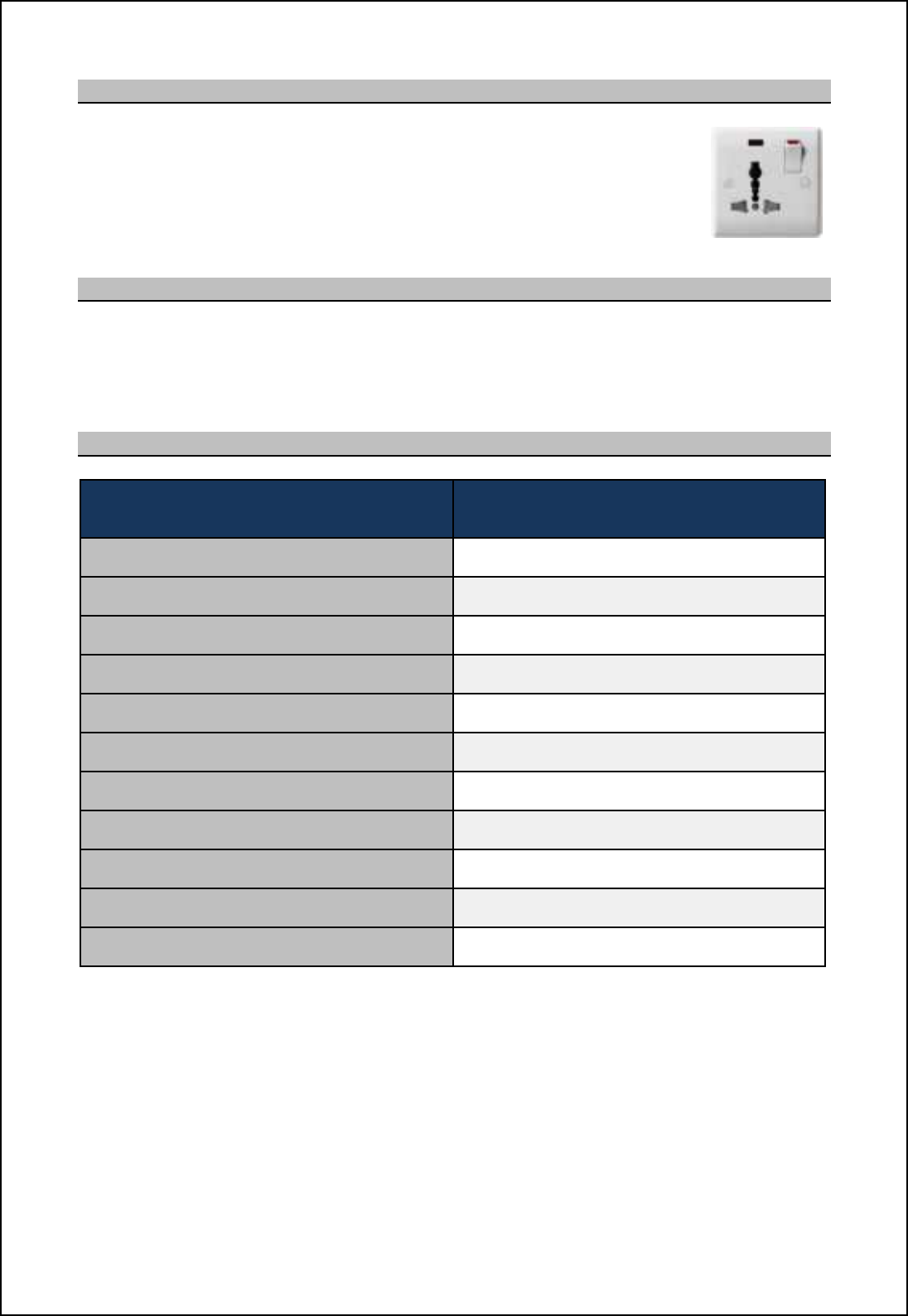
SBS-900 Shore Based Radar Systems
Chapter 10: Corrective maintenance
KH-1602-2 issue 1: Standard SBS900 Systems Operator & Maintenance Handbook
Page 178 of 240
10.7.14 Service socket
AC socket: A universal switched AC service socket is provided within
the transceiver enclosure and is located on the right hand
side of the unit.
Maximum load: The maximum load on this AC output is 100W
10.7.15 Illumination
When the AC breaker is switched ON, LED illumination is provided within the Transceiver enclosure.
There is no switch for the lighting which remains illuminated at all times when AC power is present
and switched ON.
10.7.16 Spares listing
Description Part numbers(s)
Rb[ljDs_x nl[hm]_cp_l [mm_g\fs Note 1 Please contact Kelvin Hughes Ltd for details.
Control and BITE PCA SBS-A126
Power Converter module Assembly (PSU) SBS-A146
AC line filter 45-690-0077-001
AC Mains relay (12VDC 16A) 85-200-0059-001
LED (for AC breaker) 45-6000-0118-001
MCB 10A DIN rail mounting 45-600-0102-001
Quadrature puffer PCA DTX-A295
Wind turned rotary ventilator 45-925-0032-001 (1 per)
Static Desiccator sachets 55-100-0494-002
LED strip light (1 per) 45-625-0032-001
Note 1: The SharpEye processor will be shipped as a spares replacement kit containing the main processor and a
ruggedised transport/ returns case.
SBS-900 Shore Based Radar Systems
Chapter 10: Corrective maintenance
KH-1602-2 issue 1: Standard SBS900 Systems Operator & Maintenance Handbook
Page 179 of 240
10.8 SBS-A1-1 Radar Distribution Unit
10.8.1 System part numbing
In addition to the main part number for the system, a number of options can be added to the
Radar Distribution Unit (RDU). These options are identified by a 6-digit Option number
which is added as a suffix to the main part number.
The option code contains a digit for each available option, where:
'0= Indicates the option is not required, not fitted or not available.
'1= Indicates the option is required or fitted.
'n= Indicates the particular type of option is required or fitted.
SBS-A1-4- 0 0 0 0 0 0
LAN
Interface
SBS-A129
Additional
Analogue
Output Fitted
SBS-A260
Antenna
Motor Drive
Inverter
Option
(see below)
MantaDigital
Interface Kit
SBS-A270
Antenna
Polarisation
Control Kit
SBS-A302
Product
Specific
Option
(see below)
Antenna Motor Drive Inverter Option:
To cater for global and specific customer requirements the RDU can be supplied with one of
three types of motor drive static inverter fitted.
The kits are factory fitted therefore the option needs to be specified with the main order.
Part No. Output voltage Option
Code
SBS
-
A403
440V Three Phase Inverter Kit
0
SBS
-
A229
220V Single Phase Inverter Kit
1
SBS-A404 220V Three Phase Inverter Kit 2
Product Specific Options:
This code is used for project specific variations to hardware or software and would be
defined in the specification for the system.
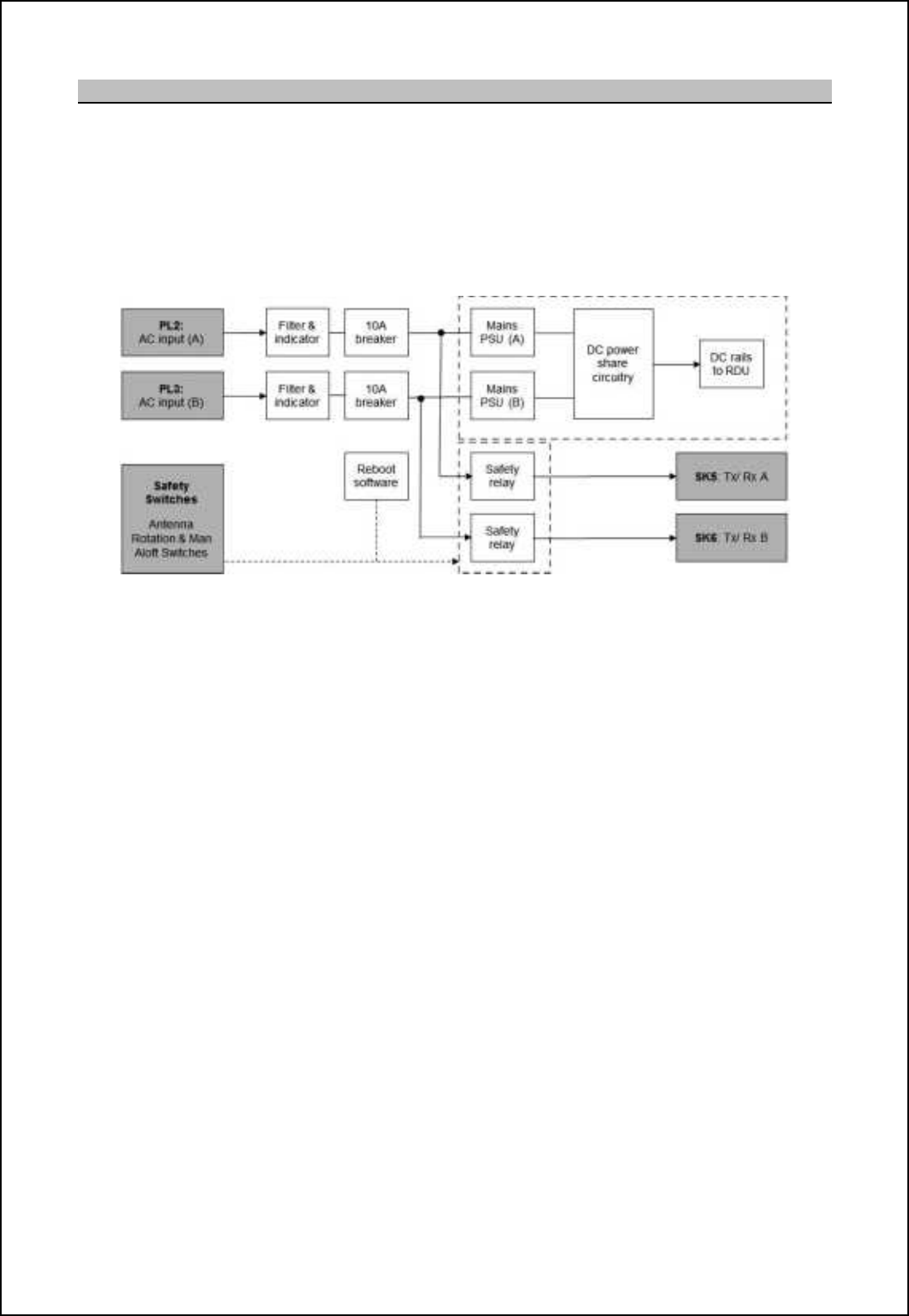
SBS-900 Shore Based Radar Systems
Chapter 10: Corrective maintenance
KH-1602-2 issue 1: Standard SBS900 Systems Operator & Maintenance Handbook
Page 180 of 240
10.8.2 AC power
Single phase supply: Dual single phase AC mains inputs are required. It is recommended that
each mains input is provided via a separate external UPS which is not
supplied as part of the SBS system.
- The AC supplies are fed to the dual redundant AC-DC power unit via a
set of user accessible over current protection devices in the form of
circuit breakers and contactor relays.
- Switched single phase AC outputs are also routed to the transceivers.
AC power loss:
Main input A: In the event of the loss of mains input A, the dual redundant AC-DC power supply will
continue to operate using the mains input B power source, however AC power to the
Tx/ Rx A (SK/ PL5) will be lost.
In an emergency and with all supplies isolated, AC power may be restored to Tx A by
temporarily reversing mains input A & B.
Main input B: In the event of the loss of mains input B, the dual redundant AC-DC power supply will
continue to operate using the mains input A power source, however AC power to the
Tx/ Rx B (SK/ PL6) will be lost.
Operators are alerted to the loss of any AC input through system alarms.
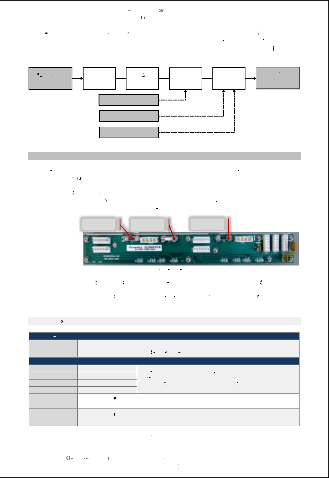
SBS
-
900 Shore
Ba
Ba
sed
Radar Systems
Chapter
10
10
:
Corrective maintenance
KH
KH
-
1602 2
issue 1
:
Standard SBS900 Systems Operator & Maintenance Handbook
Page
181
of
240
Three
-
phase:
A separate
3
-
phase input
powers the antenna drive motor via
a
static inverter
located
within the Radar Distribution Unit.
The 3
phase input is
fed to
a static
inverter
via a set of user accessible
over current protection devices
in the
form of circuit
breakers and contactor relays.
10.8.3
Fuses
Safety I
-
loop fuse:
The
+24VDC supply to the Radar Distribution Unit
safety I
-
loop is protected by a
user accessible
fu
fu
se
se
located on the top of the RDU.
PSU backplane
The power sharing PCB mounted on the back of the power supply has three
fuse
holders
which serve different purposes depending on the system installed. The
PCB also contains four self
-
resetting thermal fuses
.
Power share PCB fitted to the 45
-
690
-
0080
-
001 power supply assembly
FS7
Used on
all
standard
SBS
-
900 systems to protect the main +
5V rail
.
FS5 & FS6
O
nly used in SBS
-
A1
A1
-
11 systems
to
to
independently p
rotect each +5V
rail
(FS7 is not fitted)
.
Fuse rating
s
Safety I
-
loop
F1
500mA 240VAC
,
Ceramic, time lag, 5 x 20mm.
Kelvin Hughes part number
45
45
650
0060
002
Power supply
F1
F1
+24VDC @ 3A
Self
-
resetting thermal fuses
.
Self
resetting thermal fuses cannot be replaced or manually reset. If a
fault conditi
on exists, switch the system OFF
and allow the thermal fuse
to reset.
F2
F2
+15VDC @ 1.85A
F3
F3
-
15VDC @ 0.9A
F4
F4
+5VDC @ 3A
FS5
10A 250V
, ceramic, time lag, 5 x 20mm.
Please contact Kelvin Hughes for the correct part number
FS6 & 7
15A 250V, c
eramic, time lag, 5 x 20mm.
Please contact Kelvin Hughes for the correct part number
Replacement fuses must be of the
exact
type
specified above.
PL
PL
1:
3
-
phase
input
Filter and
indicator
6.0
A
break
er
er
Contactor
Motor
inverter
Safety switch
Antenna RPM control
Motor ON/ OFF control
SK4:
3
-
phase
output to
a
ntenna motor
FS6
FS7
FS5
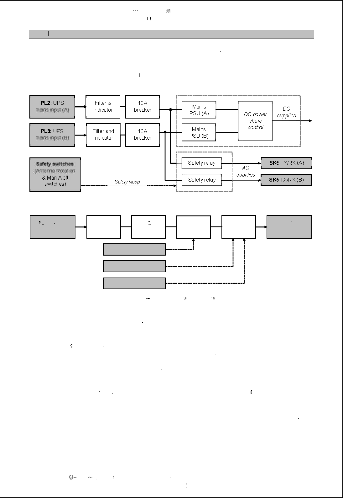
SBS
-
900 Shore
Ba
Ba
sed
Radar Systems
Chapter
10
10
:
Corrective maintenance
KH
KH
-
1602 2
issue 1
:
Standard SBS900 Systems Operator & Maintenance Handbook
Page
182
of
240
10.8.4
Breakers
The Radar Distribution Unit
is fitted with three
user accessible DIN rail mounted earth leakage trips/
breakers located in the base of the RDU behind the main access door.
The output of the breakers is fed to the
rest of the
system via contactors that are controlled by the
RDU as shown below.
RDU Single phase AC input schematic
RDU
single and 3
-
phase AC input
and breaker
schematic
AC power indication:
When AC supplies are connected to the RDU, LED indicators illuminate on
the
breakers regardless of their state indicating that AC mains is present
within the system.
Earth leakage
Due to the use of EMC filters on all AC supply inputs, earth leakage current
to a
maximum of
100mA
will exist on the
3
-
phase input.
All parts of the
system must be fully and correctly earthed prior to connecting
any source of AC power.
RCD trips:
I
f an RCD trip is fitted in the supply outlet it must be a
1
00mA RCD Type A or
similar.
Spare:
If replaced, the breakers within the RDU must be of the exact
same type
PL
PL
1:
3
-
phase
input
Filter and
indicator
6.0
A
breaker
Contactor
Motor
inverter
Safety switch
Antenna RPM control
Motor ON/ OFF control
SK4:
3
-
phase
output to
a
ntenna motor
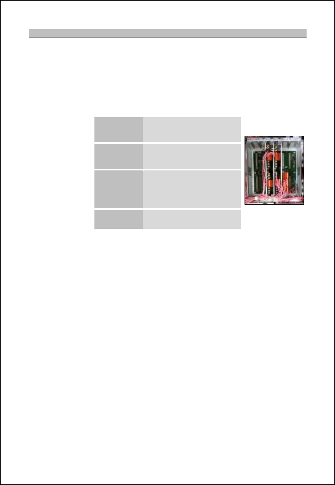
SBS-900 Shore Based Radar Systems
Chapter 10: Corrective maintenance
KH-1602-2 issue 1: Standard SBS900 Systems Operator & Maintenance Handbook
Page 183 of 240
10.8.5 RDU overview
The Radar Distribution Unit provides the interface between the transceiver enclosure [h^ nb_ om_lm
command and display system, track extractor and optional service display.
The RDU comprises on the following main components:
Processor: A card frame mounted in the top half of the unit carries the modular interface
system backplane (MISB) and modular interface system modules (MISM).
The MISM modules used in the SBS-900 series are:
Radar
Processing
Module
Type 5
NTX-A462
SharpEye radar data and control and
LAN output
RDU processor backplane
Modular radar
I/O
type 9
NTX-A477 (3 off)
Analogue radar input/ output circuitry
for track extractor, service display
and spare output.
Modular
communications
module type 11
NTX
-
A478 Serial RS232 or
RS422
communications to service display
and track extractor.
CANBus communication to optional
Kelvin Hughes MANTADigital
processor.
Modular signal
I/O
type 4 Mk 2
NTX-A490
Safety and security switch inputs and
inverter control
Power supplies: DC power for the RDU is provided by a dual redundant auto ranging power
supply. The power unit has auto-ranging inputs so manual voltage setting is
not required.
Three-phase inverter: A three-phase inverter that provides power for the antenna sub-assembly
motor. The Inverter provides a 'soft-start' of nominally 2 seconds and a 'soft-
stop' (braking) of nominally 10 seconds. This reduces the high currents
associated with starting and stopping a motor under load.
AC breakers: The RDU contains a set of internally DIN rail mounted breakers for the single
and three-phase AC mains inputs.
The DIN rail also contains contactor relays which isolate the mains supplies
when the safety i-loop (Antenna Rotation or Man Aloft Switches) is broken.

SBS-900 Shore Based Radar Systems
Chapter 10: Corrective maintenance
KH-1602-2 issue 1: Standard SBS900 Systems Operator & Maintenance Handbook
Page 184 of 240
Example of an RDU
Shown with door removed for clarity
MISM processor backplane and cards
Dual redundant AC-DC power supply
Inverter
Breakers and relays for single & three-phase
supplies
Connections to
transceiver enclosure, the
external control system
and optional service
display
Single and three-phase
AC input and output
connections Earth stud
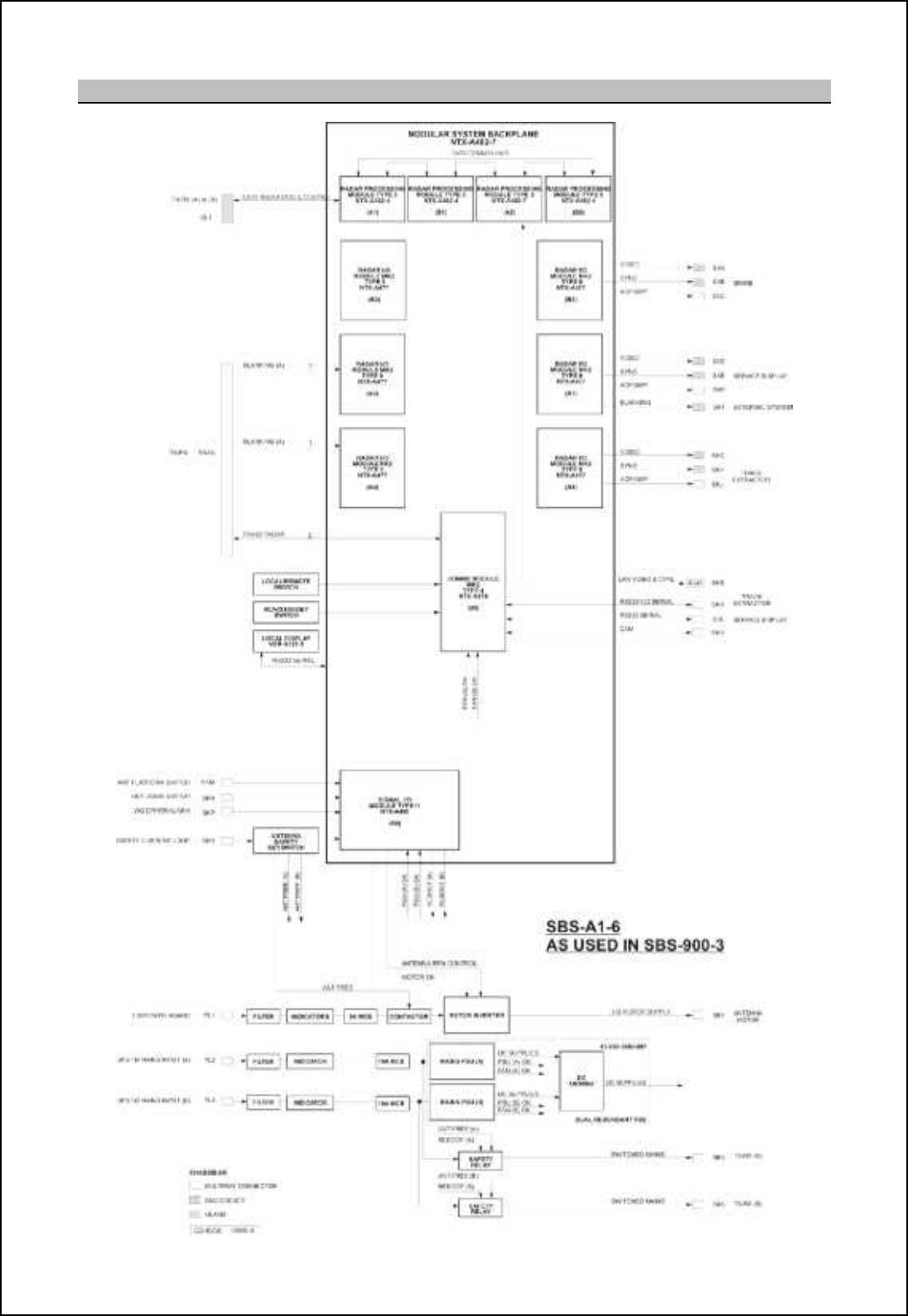
SBS-900 Shore Based Radar Systems
Chapter 10: Corrective maintenance
KH-1602-2 issue 1: Standard SBS900 Systems Operator & Maintenance Handbook
Page 185 of 240
10.8.6 Schematic

SBS-900 Shore Based Radar Systems
Chapter 10: Corrective maintenance
KH-1602-2 issue 1: Standard SBS900 Systems Operator & Maintenance Handbook
Page 186 of 240
Page intentionally blank
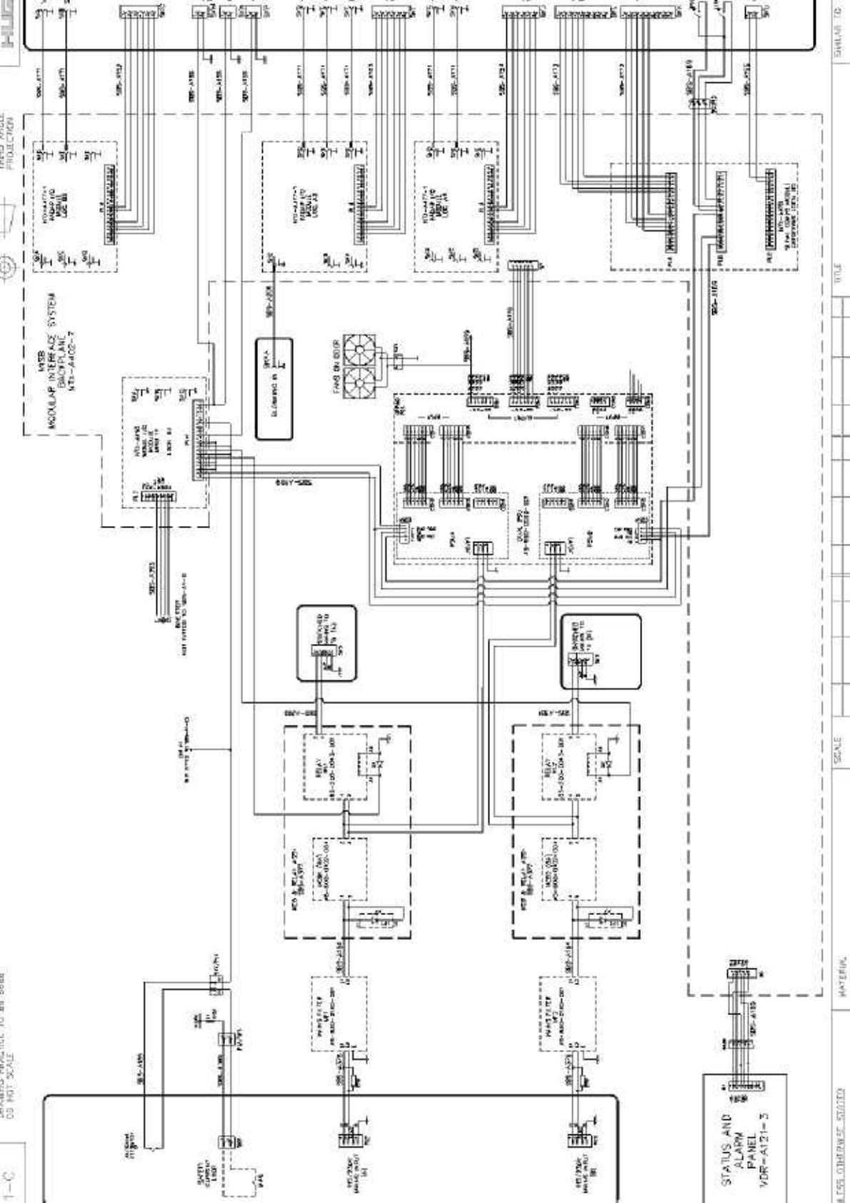
Page intentionally blank
SBS-900 Shore Based Radar Systems
Chapter 10: Corrective maintenance
KH-1602-2 issue 1: Standard SBS900 Systems Operator & Maintenance Handbook
Page 189 of 240
10.8.7 Dual redundant power supply
Dual redundant AC-DC power supply unit
Part number: 45-690-0080-001
The dual redundant power supply unit is a single unit that provides the DC output requirements of the
Radar Distribution Unit.
The PSU assembly consists of two AC-DC power units and a separate PCB that provides the power
sharing diodes for the dual redundancy output. The Radar Distribution Unit is capable of running on
just one of these power supplies (see AC power loss regarding transceiver power in previous section).
As noted below, the power supply must not be operated (switched ON) on a test bench or when
electrically and mechanically disconnected from the RDU.
WARNING: High earth leakage current devices are fitted to the dual power supply. Do
not operate the power unit disconnected from the Radar Distribution Unit Chassis and
disconnected to the MISM backplane.
WARNING: Prior to commencing any maintenance procedure, users must familiarise
themselves with the health & safety warnings noted in the planned maintenance and
health and safety sections of the system handbooks.
AC supplies: Prior to carrying out any maintenance, the system must be fully isolated
and disconnected from all single and 3-phase AC supplies. See system isolation in the
planned maintenance section of the system handbook.
UPS (Uninterruptable Power Supply): Where connected, ensure that UPS supplies to
the RDU are fully isolated prior to carrying out any maintenance task on the system.
Input: 100 to 240VAC 50/60Hz full range input
Power source: PL2: GT\af DH r<s on the base of the RDU and MCB1 supply AC power to
PSU A and to the transceiver enclosure via SK5.
PL3: GT\af DH r=s on the base of the RDU and MCB2 supply AC power to
PSU B and to the transceiver enclosure via SK6 (dual systems only).
Outputs: +24.1VDC +/- 0.6V
+15VDC +/- 0.7V
-15VDC +/-0.7V
+5VDC (4.5 to 5.9VDC)
Signals: Power good and fan fail signals
Fans: The power supply is fitted with two fans that report their status to the RDU
(Good/ Fail).
In the event of a fan failure, the power unit continues to function. Failed fans
must be replaced at the earliest safe opportunity.
Spares: The power supply is a line replacement unit and contains no field serviceable
or user adjustable parts.
Repair: The unit must not be dismantled in the field as specialist equipment is
required for testing the electrical safety barriers. Circuit diagrams are not
available for the unit.
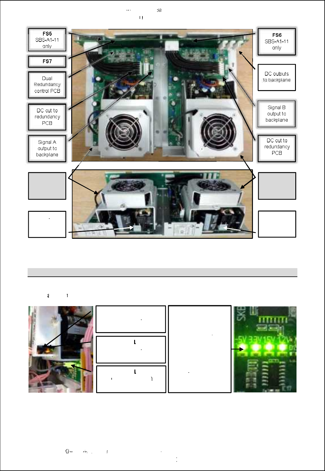
SBS
-
900 Shore
Ba
Ba
sed
Radar Systems
Chapter
10
10
:
Corrective maintenance
KH
KH
-
1602 2
issue 1
:
Standard SBS900 Systems Operator & Maintenance Handbook
Page
190
of
240
Dual redundant PSU layout
10.8.7.1
Power indication
: FCL$& NMUCPGQ?NNJGCBRMRFCNMUCPQSNNJWRFCDMJJMUGLE/( ' fQUGJJGJJSK GL?RCML@MRF
the power
supply
and
on
the backplane:
* $# WJFE.02
# " GFN<I* $# WJFE9 8 : BGC8 E<
PSU B
PSU
A
AC input
from
PL2/ MCB1
AC input
from
PL3/ MCB2
Amber LED
(Within PSU casework)
AC input OK
Green
LED
(Within PSU casework)
+24VDC OK
Green
LED
(
On external PCB
)
All power share rails OK
DC power LEDs
Located on backplane
next to the PSU
D6 = +1.2VDC OK
D7 = +1.5VDC OK
D8 =
+3.3VDC OK
D9 =
-
5VDC OK
D1 Flashing @ 1Hz
(green) = processor
running
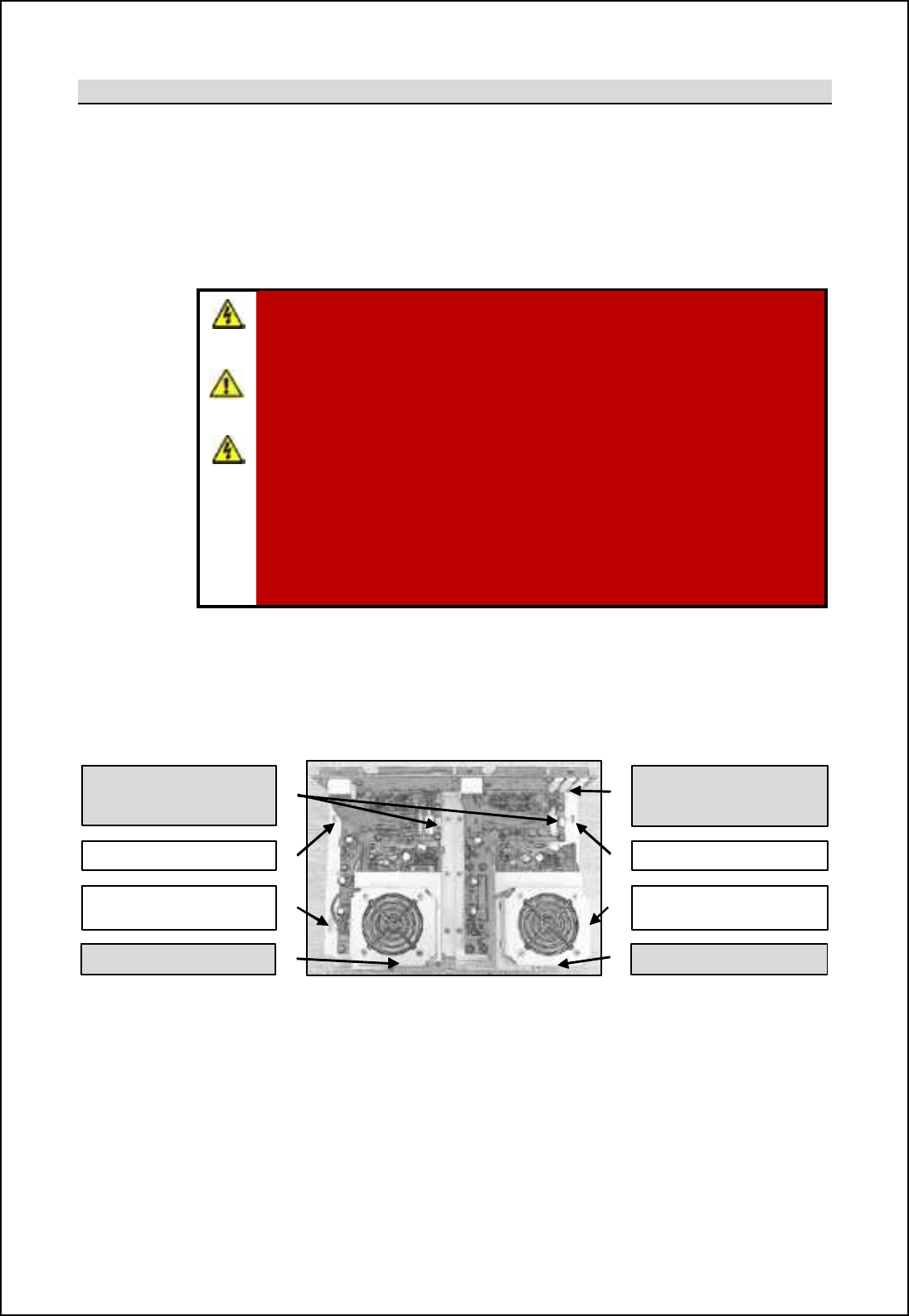
SBS-900 Shore Based Radar Systems
Chapter 10: Corrective maintenance
KH-1602-2 issue 1: Standard SBS900 Systems Operator & Maintenance Handbook
Page 191 of 240
10.8.7.2 PSU removal
Power supply fail warning: If a PSU failure warning is received on the RDU, optional service display
or command and display system, first check that AC power is present at the RDU
input and at the power supply. If AC power is available at the unit the PSU will need to
be changed.
Removal: The power supply unit is retained within nb_ Q[^[l Ccmnlc\oncih Thcn \s nqi e_s_^
locating posts and two bolts.
WARNING: High earth leakage current devices are fitted to the dual power
supply. Do not operate the power unit when mechanically or electrically
disconnected from the RDU chassis or with SK1 of the MISM backplane
disconnected.
WARNING: Prior to commencing any maintenance procedure, users must
familiarise themselves with the health & safety warnings noted in the
planned maintenance and health and safety sections of the system
handbooks.
AC supplies: Prior to carrying out any maintenance, the system must be
fully isolated and disconnected from all single and 3-phase AC supplies.
See system isolation in the planned maintenance section of the system
handbook.
UPS (Uninterruptable Power Supply): Where connected, ensure that
UPS supplies to the RDU are fully isolated prior to carrying out any
maintenance task on the system.
Prior to removal, the following connections will need to be removed:
-ORT @ [h^ A @B chjonm
- DC connections to backplane
- Signal outputs to backplane
- Earth connection to PSU mounting pillar (pink cable marked PSU)
Locating post
Main securing bolt Main securing Bolt
Obscured in drawing
Locating post
DC connections to
backplane
Signal outputs (x2) to
backplane
ORT A @B chjonORT @ @B chjon
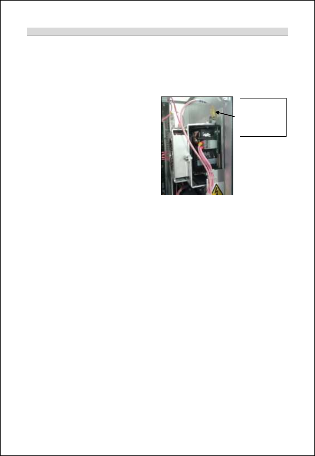
SBS-900 Shore Based Radar Systems
Chapter 10: Corrective maintenance
KH-1602-2 issue 1: Standard SBS900 Systems Operator & Maintenance Handbook
Page 192 of 240
10.8.7.3 PSU replacement
Replacement: To replace the power supply reverse the removal process shown in the previous
section.
Seating: When re-installing the unit, ensure the assembly is securely positioned onto the
locating lugs as this ensures the unit connects with the RDU chassis which acts as a
heatsink.
Earth warning: A warning label attached to the
RDU door notes that the power
supply must NEVER be operated
(switched ON) when it is
mechanically and electrically
disconnected from the RDU and
SK1 of the MISM backplane.
Earth cable: The earth cable from the
common earthing point in the
base of the RDU MUST be
reconnected to the power supply
chassis.
45
-
690
-
0080
-
001 power unit
Earth/ ground
cable from
common earth
point in base of
RDU
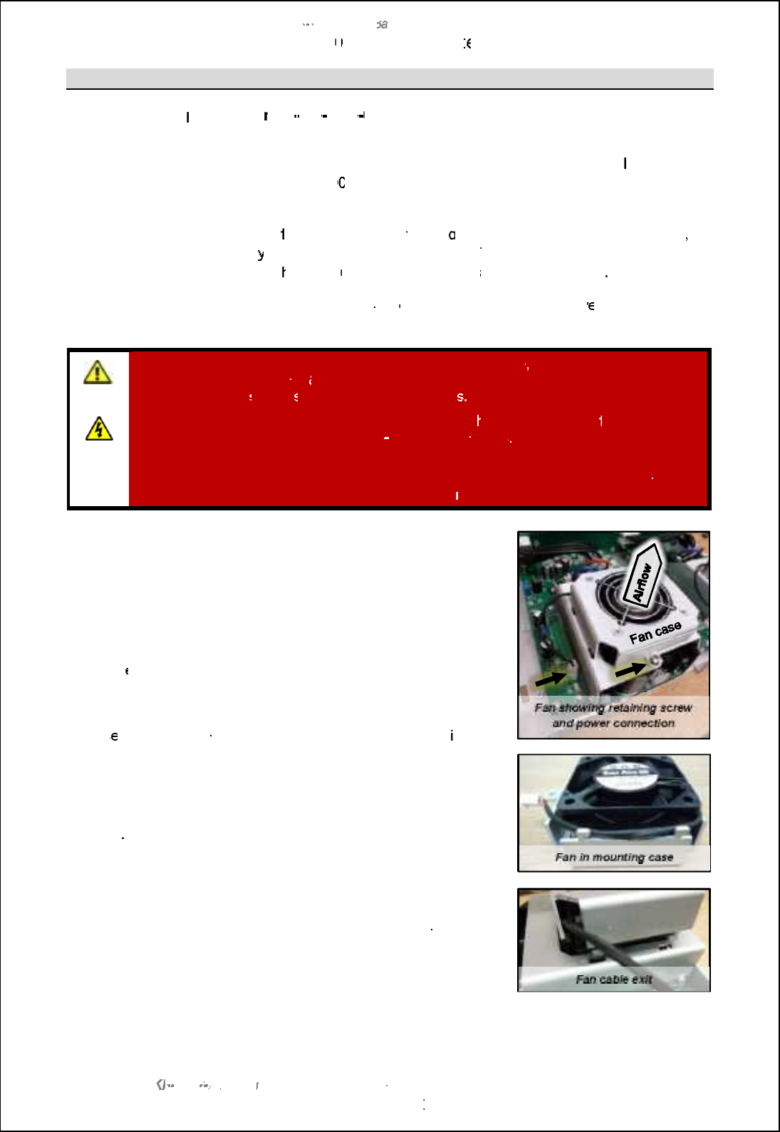
SBS
-
900 Shore
Ba
Ba
sed
Radar Systems
Chapter
10
10
:
Corrective maint
enance
KH
KH
-
1602 2
issue 1
:
Standard SBS900 Systems Operator & Maintenance Handbook
Page
193
of
240
10.8.7.4
Fan
replacement
Replacement fan
part numbe
r: 45
-
690
-
0080
003
Note: The replacement part is the fan only and does not contain the casework which must be removed from the faulty fan.
Fan life:
The two fans mounted on the RDU power supply have
a manufacturers
MTBF
(mean
time between failure)
of 50
000
hours. It is therefore recommended that the fans are
changed every 5 years as part of the routine maintenance procedures.
PSU operation:
In the event of a
failure,
a
fan failure
warnin
g is
displayed on
the RDU
front panel
,
service displa
y or command and display system.
The power unit continues to operate
when a fan fails; t
he faulty
unit must be
replaced
as soon as possible
Replacement:
Firstly identify which of the two fans
on the
power
unit
is inoperativ
e, fan (A) is the
lower fan, fan (B) is the upper fan.
WARNING
:
Prior to commencing any maintenance
procedure
, users must familiarise
themselves with the health
&
safety warnings noted in the planned maintenance
and
health and safety
section
s
of the system handbook
.
AC supplies:
Prior to carrying out
any
maintenance, t
he system must be
fully isolated
and disconnected
from the single and 3
-
phase AC supplies
. See
system isolation
in the
planned maintenance section of the system handbook.
UPS (Uninterruptable Power Supply):
Where connected, ensure that UPS supplies to
the RDU are fully isolated prior to carrying out
any
maintenance task on the system.
It is not
necessary to remove the power unit to replace the fan.
The fan is mounted in a removable case which is mounted on the
PSU chassis and restrained by a single screw and four locating
lugs.
Remove the screw and unplug the fan from the power unit.
Noting th
e orientation of the fan and the cable position, remove the
fan from its case which is retained by four nuts, bolts and washers.
Checking the direction of the airflow (blows out from the power
unit), s
ecure the replacement fan into the case using the orig
inal
nuts, bolts and washers.
Place the fan assembly onto the PSU chassis and secure with the
single screw removed earlier.
Caution
: ensure the power cable exits the casework as shown and
is not trapped under the case.
Reconnect the power to the system,
switch on and check that:
-
The replacement fan is operational.
-
The
fan fail warning messages
is no longer displayed on the
RDU, service display and
command and display system.
SBS-900 Shore Based Radar Systems
Chapter 10: Corrective maintenance
KH-1602-2 issue 1: Standard SBS900 Systems Operator & Maintenance Handbook
Page 194 of 240
10.8.8 NTX-A402 backplane
Modular Interface System Backplane (MISB)
Part number: NTX-A402-7
Backplane software: ZM-2279
The modular interface system backplane within the Radar Distribution Unit is a flexible backplane
system designed to provide interconnect and communication resources to the installed MISMs. The
modular interface system backplane incorporates a microcontroller with multiple serial communication
interfaces. A field programmable gate array (FPGA) provides digital routing and processing
resources. This allows modules to interface to other modules and the serial communication interfaces.
The modular interface system backplane also incorporates analogue cross point switching to allow
radar video to be routed between modules.
LEDs, links and test points
LEDs (all green)
D1
F
lashes when
the
microcontroller is operating
normally
D6
Lit when +1.2
V supply
present
D7
Lit when +1.5V supply present
D
8
Lit when +3.3
V supply present
D9
Lit when
-
5.0
V supply present
Links
LK1 Position A Video B2 Out routed to SW IP 04 (input) Note: Links 1 to 8
Links 1 to 8 are configured during
manufacture and should not be changed
during operation or service unless specifically
instructed to do so by Kelvin Hughes Ltd.
The default link settings are:
Links 1 to 4 = B position
Links 5 to 8 = A position
The links are used to route the video via a 16
x 16 analogue cross point switch which is
controlled by the microcontroller. This routes
any of the video inputs to one or more of the
16 video outputs. The video inputs and
outputs are 75|, 1 V peak-peak radar video.
The video cross point switch provides outputs
with the same characteristic as the input.
Position B
Video B2 Out routed to SW OP 04 (output)
LK2 Position A Video A2 Out routed to SW IP 03 (input)
Position B
Video A2 Out routed to SW OP 03
(output)
LK3 Position A Video B1 Out routed to SW IP 02 (input)
Position B Video B1 Out routed to SW OP 02 (output)
LK4
Position A
Video A1 Out routed to SW IP 01 (input)
Position B Video A1 Out routed to SW OP 01 (output)
LK5
Position A
Video
B
2 In routed to SW IP 08 (input)
Position B Video B2 In routed to SW OP 08 (output)
LK6 Position A Video A2 In routed to SW IP 07 (input)
Position B
Video A2 In routed to SW OP 07 (output)
LK7 Position A Video A1 In routed to SW IP 05 (input)
Position B
Video A1 In routed to SW OP 05 (output)
LK8 Position A Video B1 In routed to SW IP 06 (input)
Position B Video B1 In routed to SW IP 06 (output)
LK9 Open Normal operation (default)
Made Test Mode (Kelvin Hughes use only)
LK10
Open
Normal operation
(default)
Made
Setup Enabled
(setting to work use only)
Test points
TP1 Ground/ 0V TP8 +24V
TP2 Ground/ 0V TP9 +3.3 V
TP3
Ground/ 0V
TP10
+1.5 V
TP4
Ground/ 0V
TP11
+1.2 V
TP5
+5.0VDC
TP12
A
-
5V
TP6
-
15VDC
TP13
Debug (Kelvin Hughes use only)
TP7
+15V
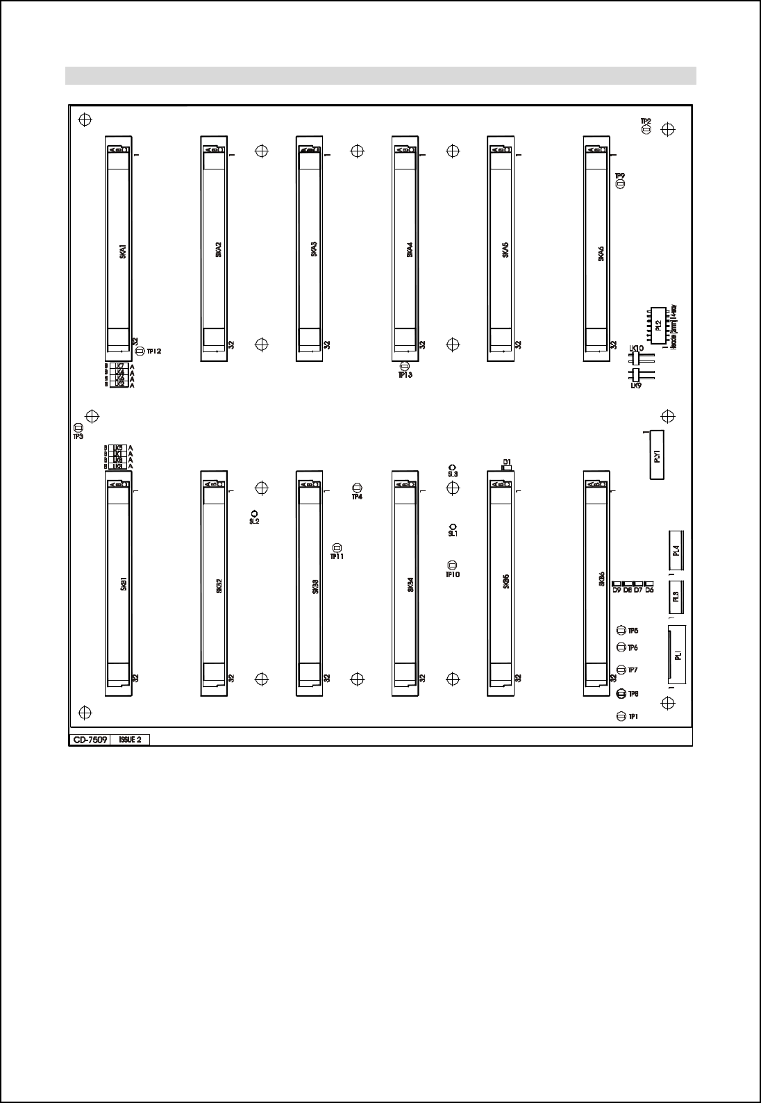
SBS-900 Shore Based Radar Systems
Chapter 10: Corrective maintenance
KH-1602-2 issue 1: Standard SBS900 Systems Operator & Maintenance Handbook
Page 195 of 240
Location of LEDs, links and test points
NTX-A402 backplane

SBS-900 Shore Based Radar Systems
Chapter 10: Corrective maintenance
KH-1602-2 issue 1: Standard SBS900 Systems Operator & Maintenance Handbook
Page 196 of 240
Power
The backplane is provided with
voltages from connector CON2
on the dual redundant power to
PL1 on the backplane:
Voltage
(DC) Tolerance PSU NTX-A402
backplane
+24
.1
V
±0.3V
CON2
-
1
PL1
-
1
+15V
±0.4
V
CON2
-
2
PL1
-
2
-
15V
±0.4
V
CON2
-
3
PL1
-
3
+5.0V
±0.2V
CON2
-
4
PL1
-
4
0V
CON2
-
5
PL1
-
5
0V
CON2
-
6
PL1
-
6
The backplane generates the following supplies internally:
Voltage Generated
from D>=rf
(all green) Test
point Notes
+12V +15V input No LED No test
point The +12V is used for the status and alarm panel and
can be measured at PL3 pin 5
+3.3V
±0.25V +5.0V input LED D8 TP9 General use
+1.5V
±0.1V +5.0V input LED D7 TP10 General use
+1.2V
±0.1V +5.0V input LED D6 TP11 FPGA core supply
A +5.0V
Regulated
by +5.0V +5.0V input No LED No tests
point
This rail is derived from the +5.0V supply via a low
pass filter network and is used to power the video
switching circuitry
A -5.0V
±0.25V -15V input LED D9 TP12 The A (analogue)-5V is also used to power the video
switching circuitry
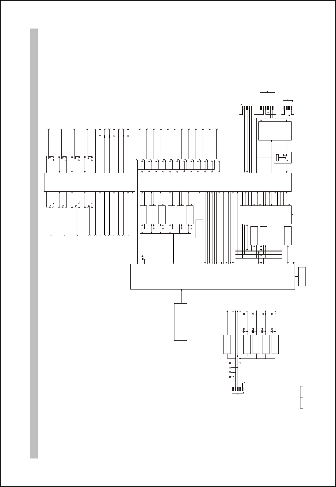
SBS-900 Shore Based Radar Systems
Chapter 10: Corrective maintenance
KH-1602-2 issue 1: Standard SBS900 Systems Operator & Maintenance Handbook
Page 197 of 240
Backplane schematic
67'0-2 - =EEG8 +
64A 7D=H8D
=62
CAN3Tx
CAN3Rx
64A 7D=H8D
=6*)
CAN4Tx
CAN4Rx
64A 7D=H8D
=6**
CAN5Tx
CAN5Rx
64A 7D=H8D
=6*+
CAN6Tx
CAN6Rx
64A 7D=H8D
=6*.
CAN1Tx
CAN1Rx
64A 7D=H8D
=6*/
CAN2Tx
CAN2Rx
ADDRESS BUS
DATA BUS
9?4E< @8@BDK
*+1@ M #1@ T */ MP S$
=6/
D4@
-@M #+./Q T */ MPS$
=60
@=6DB6BAFDB??8D
E49'J8*/092/9 //?'46
=6,
CONTROL BUS
B6F4?
G4DF T+
=61
BE6=??4FBD
J+
FJ7)
DJ7)
FJ7*
DJ7*
FJ7+
DJ7+
FJ7,
DJ7,
FJ7-
DJ7-
FJ7.
DJ7.
FJ7/
DJ7/
FJ70
DJ70
9C; 4
=6+
64A ?B 64? , FT
64A ?B 64? , DT
64A ?B 64? - FT
64A ?B 64? - DT
FJ7 4
DJ7 4
FJ7 6
DJ7 6
FJ7 8
DJ7 8
FJ7 9
DJ7 9
BE6=??4FBD
J*
EC= 5GE
88CDB@
=6.
E>4*
,L',)N
E>5*
,L',)N
E>4+
E>5+
E>4,
E>5,
E>4-
E>5-
E>4.
E>5.
E>4/
E>5/
@B7G?8 E?BF 4*
@B7G?8 E?BF 5*
@B7G?8 E?BF 4+
@B7G?8 E?BF 5+
@B7G?8 E?BF 4,
@B7G?8 E?BF 5,
@B7G?8 E?BF 4-
@B7G?8 E?BF 5-
@B7G?8 E?BF 4.
@B7G?8 E?BF 5.
@B7G?8 E?BF 4/
@B7G?8 E?BF 5/
@B7G?8 E?BF 4*
@B7G?8 E?BF 5*
@B7G?8 E?BF 4+
@B7G?8 E?BF 5+
E>4,
,*M
@B7G?8 E?BF 4, E>5 ,
,*M
@B7G?8 E?BF 5,
E>4-
,*M
@B7 G?8 E?BF 4- E>5-
,*M
@B7G?8 E?BF 5 - E>4.
,*M
@B7G?8 E?BF 4. E>5.
,*M
@B7G?8 E?BF 5. E>4/
,*M
@B7G?8 E?BF 4/ E>5/
,*M
@B7G?8 E?BF 5/
H= 78B 4, =A
H= 78B 5, =A
H= 78B 4- =A
H= 78B 5- =A
H= 78B 4. =A
H= 78B 5. =A
H= 78B 4/ =A
H= 78B 5/ =A
EI BC )*
EI =C )*
EI BC )+
EI =C )+
EI BC ),
EI =C ),
EI BC )-
EI =C )-
H= 78B
6DBEECB=AF
EI=F6<
=6*
E>4*
,*M H=78 B 4* =A
EI BC ).
EI =C ).
E>5 * ,*M H=78B 5* =A
EI BC )/
EI =C )/
E>4+,*M H=78 B 4+ =A
?>/
EI BC )0
EI =C )0
E>5+
,*M H= 78B 5+ =A
?>.
EI BC )1
EI =C )1
'.H
;8A8D4F=BA
=6*-
4'.H
%*+H
;8A8D4F=BA
=6+*
%*+H
%+-H
%*.H
'*.H
%.H
%,(,H
;8A8D4F=BA
=6+)&FD*&FD+
%,(,H
D8
+3V3V OK
%*(.H
;8A8D4F=B A
=6*,
%*(.H
D7
+1V5V OK
%*(+H
;8A8D4F=B A
=6-
%*(+H
D6
+1V2V OK
6BAFDB ?
%*+H
DT
FT
)H
DE+,+ E8D=4? CBDF
FB 4?4D@ @B7G?8
DJ+,+
;DBGA 7
;DBGA 7
FJ+,+
5B BFEFD4C
D8E8F
7=4;ABEF=6
E8D=4? CBDF
,,@<U 6?B6>
+-@<U 6?B6>
A
B
LK7
A
B
LK8
A
B
A
B
@B7G?8 =7 5GE
6BAFDB?
)H
C?* *
+
,
-
.&/
FC1
%+-H
%*.H
'*.H
%.H
FC0 FC/ FC.
76 CBI8D =A
72
'.H B>
FC*+
FC2
FC*)
FC**
?>+
?>*
A
B
LK4
A
B
LK3
A
B
A
B
E>4*
+M @B7G?8 E?BF 4*
E>4,
+M @B7G?8 E?BF 4,
E>5,
+M @B7G?8 E?BF 5,
E>4-
+M @B7G?8 E?BF 4-
E>5-
+M @B7G?8 E?BF 5-
E>4.
+M @B7G?8 E?BF 4.
E>5.
+M @B7G?8 E?BF 5.
E>4/
+M @B7G?8 E?BF 4/
E>5/
+M @B7G?8 E?BF 5/
H=78B 4* BGF
H=78B 4, BGF
H= 78B 5, BGF
H=78B 4- BGF
H= 78B 5- BGF
H=78B 4. BGF
H=78B 5. BGF
H=78 B 4/ BGF
H=78B 5/ BGF
E>5*
+M @B7G?8 E?BF 5*
H= 78B 5* BGF
E>4+
+M @B7G?8 E?BF 4+
H=78B 4+ BGF
E>5+
+M @B7G?8 E?BF 5+
H= 78B 5+ BGF
DATA
DATA
,L',)N
,L',)N
,L',)N
,L',)N
,L',)N
,L',)N
,L',)N
,L',)N
,L',)N
,L',)N
%,(,H
C?+
*
-
/
1
*)
DATA
DATA
DATA
DATA
DATA
DATA
DATA
DATA
DATA
DATA
JTAG
F@E
F6>
F7B
F7=
)H
*
+
,
-
.
/
C?-
=6*1
DJ CDB;
DJ E4@
DJ74
FJ74
DE+,+
=AF8D9468
=6*2
7*
DGA A=A;
6BAFDB?
6BAFDB?
)H
%*+H C?,
.
*
,
+& -
('%&
('$#&
BC8A 3 AB D@4? @B78
@478 3 F8EF @B 78
@478 3 E8FGC 8A45?87
BC8A 3 E8FGC =A<=5= F87

SBS-900 Shore Based Radar Systems
Chapter 10: Corrective maintenance
KH-1602-2 issue 1: Standard SBS900 Systems Operator & Maintenance Handbook
Page 198 of 240
Page intentionally blank
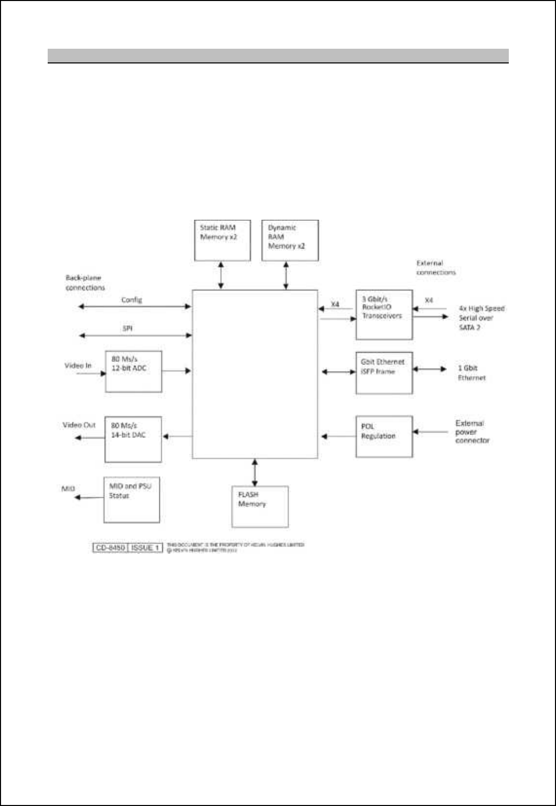
SBS-900 Shore Based Radar Systems
Chapter 10: Corrective maintenance
KH-1602-2 issue 1: Standard SBS900 Systems Operator & Maintenance Handbook
Page 199 of 240
10.8.9 NTX-A462 Radar processing module
Modular interface system module (MISM) Type 5 (Radar processing module type 5)
Part numbers NTX-A462-101 (SX) & NTX-A462-102 (FX)
Backplane locations: TBC
Overview: The purpose of the Modular Interface System Module (MISM) Type 5 (Radar
Processing Module) is to provide Field Programmable Gate Array (FPGA)
and memory resources and have the following interfaces:
- One fibre optic SFP Small form-factor pluggable transceiver connector
- Four high speed SATA II interfaces
DC power: The MISM Type 5 uses +15 V, +3.3 V and -15 V supplies from the Modular
Interface System Backplane (MISB).
Fibre Optic link: The SFP socket SK7 provides the fibre optic interface complaint to the INF-
8074i standard. The connector consists of an SFP cage and connector
assembly which can connect up to six fibre optic cables.
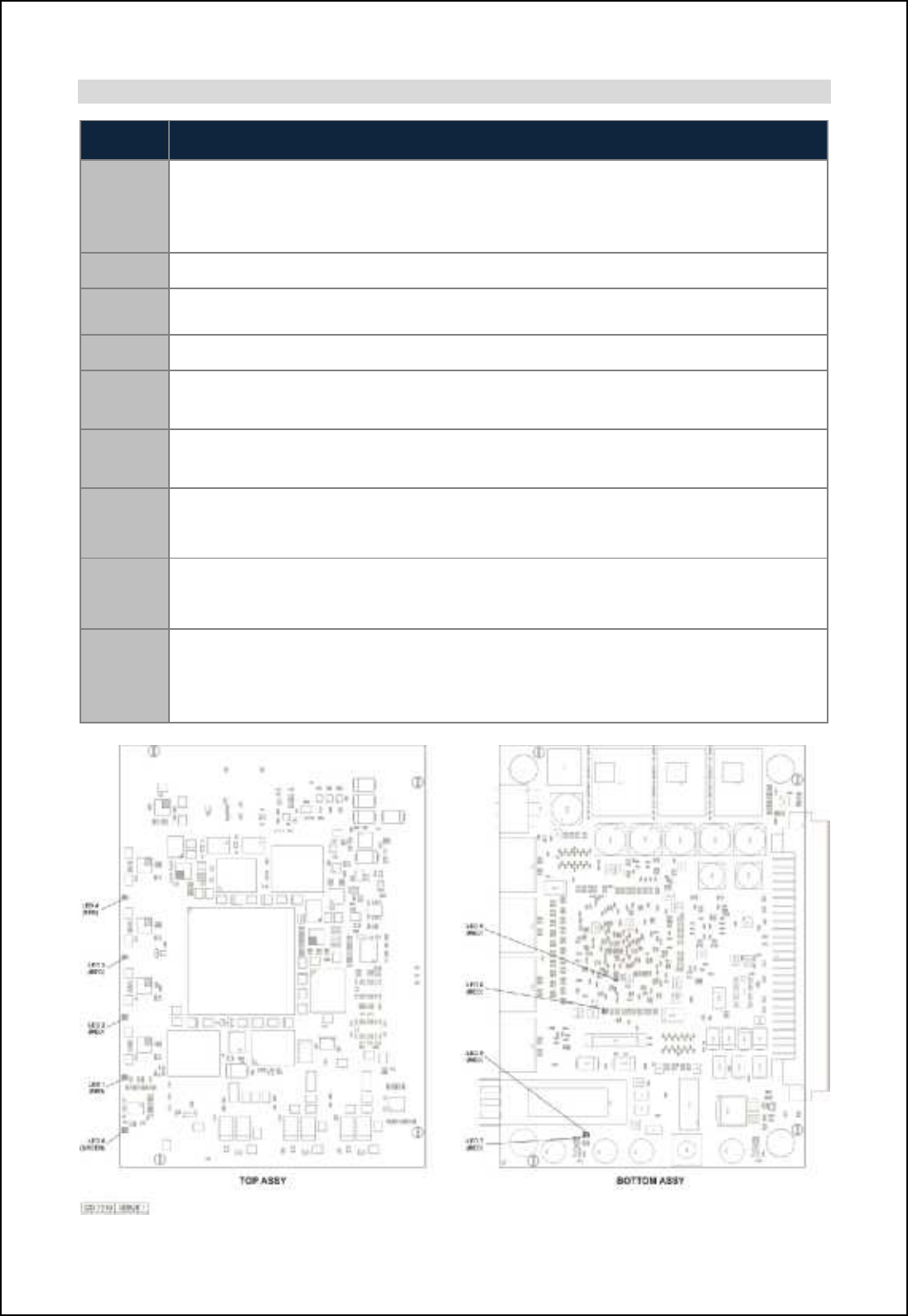
SBS-900 Shore Based Radar Systems
Chapter 10: Corrective maintenance
KH-1602-2 issue 1: Standard SBS900 Systems Operator & Maintenance Handbook
Page 200 of 240
KDCm
LED
Number
Function
LED1
"CHANNEL UP" or "DATA VALID CH1". On the NTX-A462-1 fitted in bays A1 and
B1this is "CHANNEL UP" which indicates the presence of data input from the LAN. On
the NTX-A462-3 fitted in bay A2 this is "DATA VALID CH1" which indicates the
presence of valid data input from module A1 via the SATA link.
LED2 "DATA VALID" This red LED indicates presence of decoded zero range trigger pulse.
LED3 "RUNNING" This red LED indicates FPGA is loaded and running and should normally
be flashing.
LED4 This red LED is not used.
LED5 "FPGA NOT LOADED" This Red LED indicates FPGA has failed to load and should
normally be unlit.
LED6 "FLASH MEMORY CHECKSUM ERROR" This Red LED indicates a checksum error in
flash memory and should usually be unlit.
LED7 "SFP TX FAULT" This Red LED indicates failure of SFP TX module or that the module
is not fitted. This LED should be lit on NTX-A462-1 fitted in bays A1 and B1 and unlit on
NTX-A462-3 fitted in bay A2.
LED8 "POWER SUPPLIES OK" This Green LED illuminates when the power monitor IC36
detects the power rails are within limits. The +5 V, +3.5 V, +1.8 V, AVTTRX, AVTTTX,
AVCC and AVCCPLL voltage rails are monitored. This LED should normally be on.
LED9
"SFP LOSS" This Red LED indicates a Loss Of Signal (carrier) such as when the
media is disconnected or broken, or when the signal level is below an acceptable level.
It is also illuminated in the absence of an SFP due to pull-up R164. This LED should
normally be off.

SBS-900 Shore Based Radar Systems
Chapter 10: Corrective maintenance
KH-1602-2 issue 1: Standard SBS900 Systems Operator & Maintenance Handbook
Page 201 of 240
10.8.10 NTX-A477-1 radar I/O module
Modular interface system module (MISM) Type 9 (radar I/O module Mk 2)
Part number NTX-A477-1
Backplane locations: A3 (service display output)
A4 (Track extractor output)
B3 (Spare output)
Overview: The radar I/O module interfaces the following signals with the backplane:
- Analogue radar input (video, sync, azimuth and heading line)
- Analogue radar output (video, sync, blanking, azimuth and heading line)
- An auxiliary video channel is used for an ESM Blanking pulse input from
the Tx/ Rx
- A blanking output is used to output an ESM blanking pulse
The board is controlled by the backplane which selects the radar input from
one of many input channels and route the data to the output channels using
the video switching circuitry.
Video IN: Radar video is received on SKA at +1.0V to +6.0V peak-to-peak with an input
impedance of 75ohms and is routed to the radar I/O PCB.
The video is applied to an operational amplifier which provides a 2.0V peak-
to-peak output which is dropped to 1.0V peak-to-peak (TP5) for application to
the backplane. The video amplifier gain and offset is manually set and
controlled from the backplane at 1.0V peak-to-peak ensuring the correct input
level. The offset circuit allows the amplifier to compensate for any DC offset in
the input signal, thus providing the correct signal level to the backplane.
LED D5 flashes when the video input is detected by the backplane.
Video OUT: Video out of the radar I/O PCB is sent to the backplane terminated at 75ohms
to provide an output of between +1.0V to +5.0V peak-to-peak to SKD which
can be measured at TP9.
Sync IN: Radar sync is input on SKB at 3.0V to 15V pulses and an input impedance of
75ohm and is routed to the radar I/O PCB. The sync is processed and passed
via a high speed differential comparator to the backplane as an LVTTL signal
(TP8).
LED D4 is lit when the sync input is detected by the backplane.
Sync OUT: The sync output from the radar I/O PCB is amplified by to provide sync
pulses between 3.0V and 14V on SKE and TP11. The sync level is controlled
from the backplane and an operational amplifier.
Aux video/ blanking: The auxiliary video input/ blanking from the radar I/O PCB is amplified to
provide blanking pulses between 3.0V and 14V on SKF and TP10. The
blanking pulse level is controlled from the backplane and an operational
amplifier.
Azimuth: The Azimuth inputs (Az1 and Az2) utilises the same circuitry as for a pulsed
format, but are all terminated by a link selectable 120|resistor (links 1, 2 & 6
for RS422). Azimuth can be received as pulsed, quadrature, RSS422 or
+5.0V to +17.5V peak-peak (adjustable during system configuration/ factory
set to +15V).
SBS-900 Shore Based Radar Systems
Chapter 10: Corrective maintenance
KH-1602-2 issue 1: Standard SBS900 Systems Operator & Maintenance Handbook
Page 202 of 240
Heading line: The heading line utilises the same circuitry as for a pulsed format, but are all
terminated by a link selectable 120|resistor.
ARP/ Heading line signals can be received as pulsed, quadrature, RSS422 or
+5.0V to +17.5V peak-peak (adjustable during system configuration, factory
set to +15V).
LEDs, links and test points
LEDs (all green) LED Status
D4 Lit when sync pulses (in & out) present at the backplane ON An input is being received
and an output generated at
the backplane
D5 Lit when video signals are present
D6 Lit when auxiliary video (blanking) pulses are present Flashing Only an input or an output is
available at the backplane
D7 Lit when azimuth signals are present
D8 Lit when heading line pulses are present OFF No input is being received or
no output is available from the
backplane
from
the backplane
D10 Lit when +5.0V is present
D11 Lit when -5.0V is present
Links (factory default settings in BOLD)
LK1 Open Heading line un-terminated
Made
G_[^cha fch_ n_lgch[n_^ 01/| `il QR311
LK2 Open Azimuth 2 un-terminated
Made
Azimuth 2 terminated
01/| `il QR311
LK3 Position A Pulsed heading line input
Position B Closing contact heading line input
LK4
Open
Heading line input for >5VDC
Made Heading line input for RS422 levels or <5VDC
LK5
Open
Azimuth 1 input for >5VDC
Made
Azimuth 1 input
for RS422 levels or <5VDC
LK6 Open Azimuth 1 un-terminated
Made
@tcgonb 0 n_lgch[n_^ 01/| `il QR311
LK7 Open Azimuth 2 input >5VDC
Made
Azimuth 2 input for RS422 levels or <5VDC
LK8
Position A
Variable azimuth and heading line amplitude
Position B RS422 azimuth and heading line level amplitude
Test points
TP1
Heading line IN LVTTL heading line pulses (3.3VDC)
TP2
Az1 IN LVTTL pulse for each azimuth pulse
TP3
Not accessible for service or maintenance use
TP4
Az2 IN LVTTL pulse for each azimuth pulse
TP5
Video IN 1.0V peak to peak video
TP6
Analogue ground 0V
TP7
Aux video IN LVTTL video or blanking pulses
TP8
Sync IN LVTTL pulses
TP9
Video OUT 1.0V to 5.0V peak to peak video
TP10
Blanking pulse OUT 3.0V to 14V pulses
TP11
Sync OUT 3.0V to 14V pulses
TP12
Analogue ground 0V
Power
The Radar I/O PCA uses +24V, +15V, +3.3V and -15V directly from the backplane. The +24V is
applied to a Voltage Regulator to generate a +5.0V and -5.0V supply for the internal circuits.
- LED D10 is lit when the +5.0V supply is present.
-LED D11 is lit when the -5.0 V supply is present.
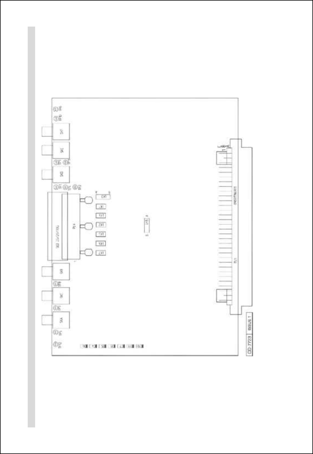
SBS-900 Shore Based Radar Systems
Chapter 10: Corrective maintenance
KH-1602-2 issue 1: Standard SBS900 Systems Operator & Maintenance Handbook
Page 203 of 240
Location of LEDs, links and test points
NTX-A477-1 radar I/O module NTX-A477-1 schematic
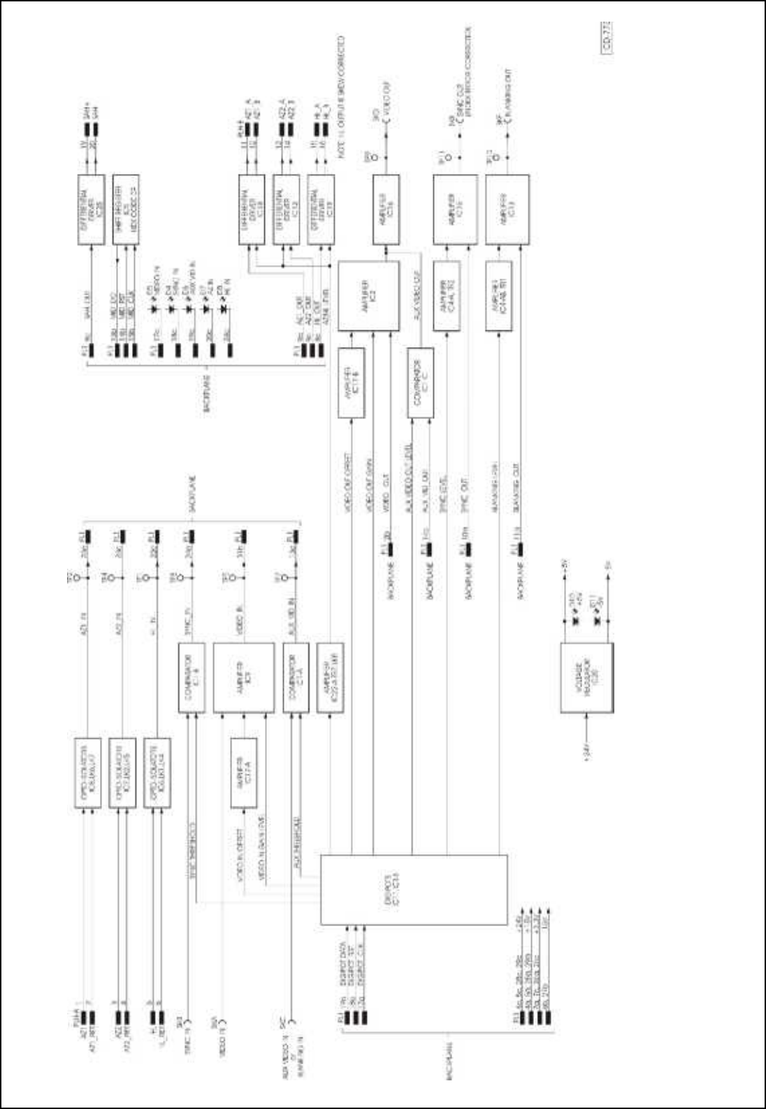
SBS-900 Shore Based Radar Systems
Chapter 10: Corrective maintenance
KH-1602-2 issue 1: Standard SBS900 Systems Operator & Maintenance Handbook
Page 204 of 240
SBS-900 Shore Based Radar Systems
Chapter 10: Corrective maintenance
KH-1602-2 issue 1: Standard SBS900 Systems Operator & Maintenance Handbook
Page 205 of 240
10.8.11 NTX-A478 serial coms module
Modular interface system module (MISM) type 4 Mk2 serial coms module
Part number NTX-A478
Backplane location: B5
Overview: The serial communications module within the Radar Distribution Unit is
controlled by the backplane and provides the following interfaces:
- Three CANBus V2.0B interfaces.
- Six RS232/422 serial interfaces.
- Four opto-isolated parallel inputs and/ or relay isolated outputs.
CANBus: The V2.0B CAN bus controllers are located on the backplane; the PCB only
provides the physical interface to the external CAN bus. The board converts
and buffers the CAN bus LVTTL transmit and receive signals.
RS232/422 serial interfaces: The board has six identical RS232/422 interfaces. The LVTTL serial
transmit and receive signals on the backplane interface are configured for bi-
directional operation by a multi-protocol transceiver. Each input can be
configured by links which are MADE for RS232 and OPEN for RS422.
Parallel inputs/ outputs: The PCB has four identical parallel input/output ports. Each port can be
configured as an input and/or output, with the following options (port 1 shown
below as an example):
- Opto-isolated input, with LK10 set to Position B and LK13 OPEN.
- Isolated output, with LK10 and LK11 both set to position A, LK12 not fitted
and LK13 MADE.
- Input and output, with LK10 set to Position A and LK13 OPEN.
LEDs, links and test points
LED (green)
D
1
Lit when
internally generated +5.0V is present
Links (factory defaults in BOLD)
LK1
Open
CANBus 1 un
-
terminated
Made B@MAom 0 n_lgch[n_^ chni 01/|
LK2 Open CANBus 2 un-terminated
Made
CANBus 2 terminated into
01/|
LK3 Open CANBus 3 un-terminated
Made
B@MAom 2 n_lgch[n_^ chni 01/|
LK4 Open Serial interface 1 set to RS422 operation
Made
Serial interface 1 set to RS232 operation
LK5
Open
Serial interface 2 set to RS422 operation
Made Serial interface 2 set to RS232 operation
LK6
Open
Serial interface 3 set to RS422 operation
Made
Serial interface 3 set to RS232 operation
LK7 Open Serial interface 4 set to RS422 operation
Made
Serial interface 4 set to RS232 operation
LK8 Open Serial interface 6 set to RS422 operation
Made
Serial interface 6 set to RS232 operation
LK9
Open
Serial interface 5 set to RS422 operation
Made
Serial interface 5 set to RS232 operation
SBS-900 Shore Based Radar Systems
Chapter 10: Corrective maintenance
KH-1602-2 issue 1: Standard SBS900 Systems Operator & Maintenance Handbook
Page 206 of 240
Links (factory defaults in BOLD)
LK10 Position A Isolated output
Parallel 1
Position B
Opto
-
isolated output
LK11 Open Normally open output contact
Position A
Position B
Normally closed output contact
LK12 OPEN Isolated output
Position A
Non
-
isolated output ground
Position B Non-isolated output +15V
LK13
OPEN
Opto-isolated input
MADE
Isolated output
LK14 Position A Isolated output
Parallel 2
Position B
Opto
-
isolated output
LK15 Open Normally open output contact
Position A
Position B
Normally closed output contact
LK16 OPEN Isolated output
Position A
Non
-
isolated output ground
Position B Non-isolated output +15V
LK17 OPEN Opto-isolated input
MADE
Isolated output
LK18 Position A Isolated output
Parallel 3
Position B Opto-isolated output
LK19
Open
Normally open output contact
Position A
Position B
Normally closed output contact
LK20 OPEN Isolated output
Position A Non-isolated output ground
Position B
Non
-
isolated output +15V
LK21 OPEN Opto-isolated input
MADE
Isolated output
LK22 Position A Isolated output
Parallel 4
Position B Opto-isolated output
LK23
Open
Normally open output contact
Position A
Position B
Normally closed output contact
LK24 OPEN Isolated output
Position A Non-isolated output ground
Position B
Non
-
isolated output +15V
LK25 OPEN Opto-isolated input
MADE
Isolated output
Test points
TP1
Ground / 0V
TP2
Ground / 0V
Power
The PCB uses +15V and +3.3V supplies directly from the backplane.
A +5.0V DC rail is generated on the PCB from the +15V supply, LED D1 (green) is lit when this +5.0V
supply is present.
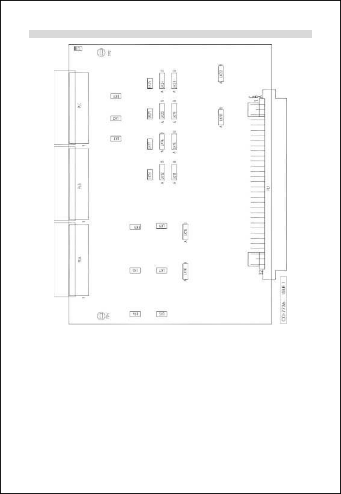
SBS-900 Shore Based Radar Systems
Chapter 10: Corrective maintenance
KH-1602-2 issue 1: Standard SBS900 Systems Operator & Maintenance Handbook
Page 207 of 240
Location of LEDs, links and test points
NTX-A478 Serial communications PCB
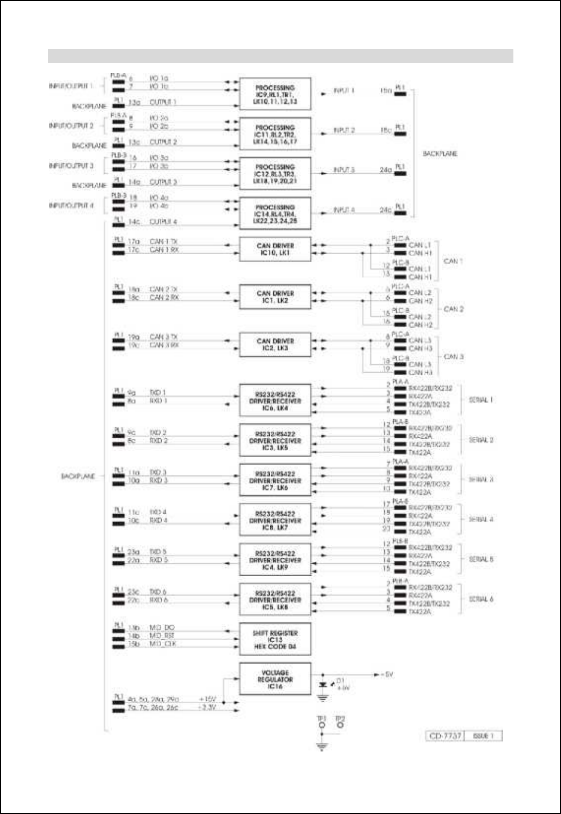
SBS-900 Shore Based Radar Systems
Chapter 10: Corrective maintenance
KH-1602-2 issue 1: Standard SBS900 Systems Operator & Maintenance Handbook
Page 208 of 240
NTX-A478 schematic
SBS-900 Shore Based Radar Systems
Chapter 10: Corrective maintenance
KH-1602-2 issue 1: Standard SBS900 Systems Operator & Maintenance Handbook
Page 209 of 240
10.8.12 NTX-A490 signal I/O module
Modular interface system module type 11 signal I/O module
Part number NTX-A490
Backplane location: B4
Overview: The signal I/O Module within the Radar Distribution Unit is controlled by the
backplane and provides the following interfaces:
- Three switched relay outputs: F-OUT, S1-OUT and S2-OUT.
- Three co-axial outputs: SKA, SKB and SKC.
- Four I/O channels configurable using links to be inputs or outputs.
- Two Input only channels and two output only channels.
Coaxial outputs: There are three identical coaxial outputs with adjustable voltage levels of
between 5.0V and 15VDC.
Switched relay outputs: There are three Identical Relay outputs. These are primarily used to control
the 3-phase inverter which supplies power for the gearbox motor.
Input/ outputs: Configurable ports (channels 1 to 4): The board has four configurable input/
output ports that can be configured using links to be:
- A pulse input with a relay output.
- An opto-isolated input.
- An isolated input.
- An input and output port.
Non configurable ports (channels 5 and 6): Pulsed inputs with a relay
outputs.
LEDs, links and test points
LED (green)
D
24
Lit when
internally generated +5.0V is present
D
24
Lit when
internally generated
-
5.0V is present
Links
LK1
Position A
Pulse in/ Relay out
(default)
Position B Differential output
LK2 Position A Pulse in/ Relay out
Position B
Differential output
LK3 Position A +15V ref for input; input action low on IOB
Position B
Input drive from IOA
LK4 Position A Closing contact relay
Position B
Opening
contact relay
LK5
Position A
Ground ref for relay
Position B +15V ref for relay
LK6
Made
Connects IOB to relay ref
Open No action
LK7 Position A Pulse in/ Relay out
Position B
Differential output
LK8 Position A Pulse in/ Relay out
Position B
Differential output
LK9 Position A +15V ref for input; input action low on IOB
Position B
Input drive from IOA
LK10
Position A
Closing contact relay
Position B Opening contact relay
LK11
Position A
Ground ref for relay
Position B +15V ref for relay
SBS-900 Shore Based Radar Systems
Chapter 10: Corrective maintenance
KH-1602-2 issue 1: Standard SBS900 Systems Operator & Maintenance Handbook
Page 210 of 240
Links
LK12 Position A Connects IOB to relay ref
Position B
No action
LK13 Position A Pulse in/ Relay out
Position B Differential output
LK15
Position A
+15V ref for input; input action low on IOB
Position B Input drive from IOA
LK16
Position A
Closing contact relay
Position B Opening contact relay
LK17 Position A Ground ref for relay
Position B
+15V ref for relay
LK18 Position A Connects IOB to relay ref
Position B
No action
LK19 Position A Pulse in/ Relay out
Position B Differential output
LK20
Position A
Pulse in/ Relay out
Position B Differential output
LK21
Position A
+15V ref for input; input action low on IOB
Position B Input drive from IOA
LK22 Position A Closing contact relay
Position B
Opening contact
relay
LK23 Position A Ground ref for relay
Position B
+15V ref for relay
LK24 Position A Connects IOB to relay ref
Position B No action
LK25
Position A
Pulse in/ Relay out
Position B Differential output
LK26
Position A
Pulse in/ Relay out
Position B Differential output
LK27 Position A Closing contact relay
Position B
Opening contact relay
LK28 Position A Ground ref for relay
Position B
+15V ref for relay
LK29 Position A Pulse in/ Relay out
Position B Differential output
LK30
Position A
Pulse in/ Relay out
Position B Differential output
LK31
Position A
Closing contact relay
Position B Opening contact relay
LK32 Position A Ground ref for relay
Position B
+15V ref for relay
LK33 Position A Direct drive pulse out
Position B
50
| n_lgch[ncih
Not fitted AC coupled out
LK34 Position A Direct drive pulse out
Position B
50
| n_lgch[ncih
Not fitted AC coupled out
LK35
Position A
Direct drive pulse out
Position B 50| n_lgch[ncih
Not fitted
AC coupled out
Test points
TP1
Gnd
TP8
Input 2 (TTLV level)
TP2
Gnd
TP9
Input 3 (TTLV level)
TP3
Pulse output (SKB)
TP10
Input 4 (TTLV level)
TP4
+5.0V
TP11
Pulse output (SKA)
TP5
Pulse output (SKC)
TP12
Input 5 (TTLV level)
TP6
-5.0V
TP13
Input 6 (TTLV level)
TP7
Input 1 (TTLV level)
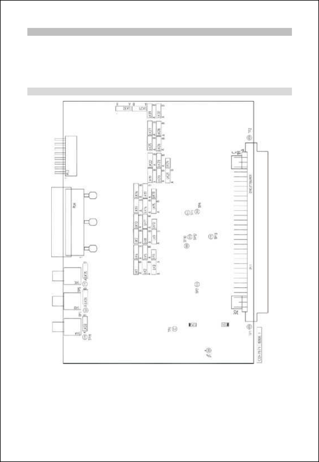
SBS-900 Shore Based Radar Systems
Chapter 10: Corrective maintenance
KH-1602-2 issue 1: Standard SBS900 Systems Operator & Maintenance Handbook
Page 211 of 240
Power
The board uses +24V, +15V and +3.3V supplies directly from the backplane. A +5.0V and -5.0V
supply is generated o the PCB from the +24V rail.
- LED D24 (green) is lit when the +5.0V supply is present.
- LED D25 (green) is lit when the -5.0V supply is present.
Location of LEDs, links and test points
NTX-A490 signal I/O module
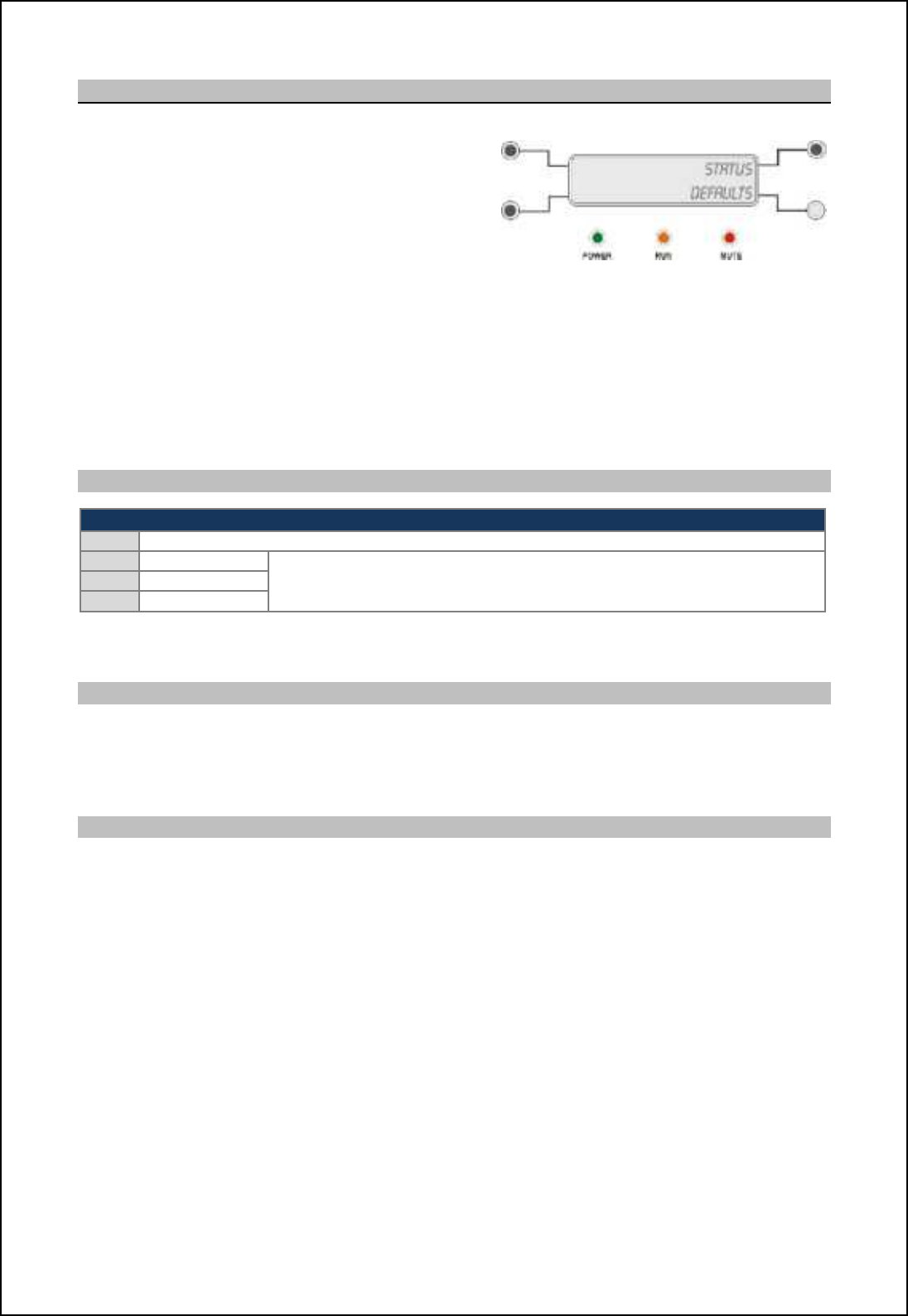
SBS-900 Shore Based Radar Systems
Chapter 10: Corrective maintenance
KH-1602-2 issue 1: Standard SBS900 Systems Operator & Maintenance Handbook
Page 212 of 240
10.8.13 VDR-A121-3 status and control PCB
The Status and Control PCB Assembly (Front panel)
provides indication of the unit status by means of an
LCD display and a set of LEDs, and provides control
of the unit functions by means of four pushbutton
switches.
The unit is interfaced via a bi-directional RS232 serial
data link on PL1 to SK3 on the backplane.
The four switches are momentary action pushbutton switches. The lower right switch also contains an
integral LED indication, which may or may not be used depending on the requirements of the parent
equipment.
When a switch is pressed the interface to the microprocessor is pulled down to ground and this is
detected by the microprocessor. The switch functions and LED display are determined by the
configuration software, not by the on-board software.
LEDs, links and test points
LEDs
D
1
Red LED - Lit when unit is being programmed (Kelvin Hughes use only)
D
2
Red LED
Front panel LEDs: The LED status depends on system activity.
D3
Green LED
D4
Yellow LED
Note: PL4 is used for programming the PCB during manufacture and must not be used for any other purpose. Caution:
Unauthorised use of this port can rendering the PCB defective.
Power
The board uses the +12V rail direct from the backplane which is received on PL1 pins 1 & 2. (+12V)
+12V DC from PL1 pins 1 and 2.
@ 4-/U l[cf cm chn_lh[ffs a_h_l[n_^+ nb_l_ [l_ hi KDCm il n_mn jichnm `il nbcm l[cf-
Software
The status & control PCB runs ZM-2010 software which has no user configurable parameters.
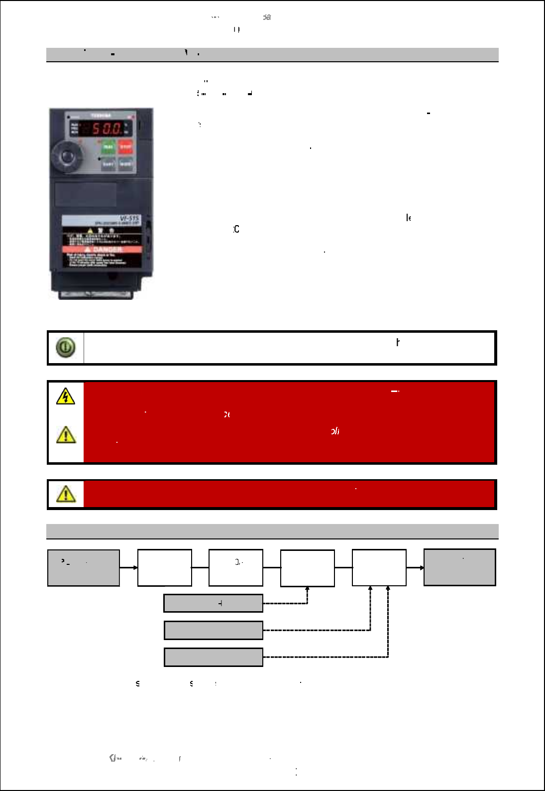
SBS
-
900 Shore
Ba
Ba
sed
Radar Systems
Chapter
10
10
:
Corrective maintenance
KH
KH
-
1602 2
issue 1
:
Standard SBS900 Systems Operator & Maintenance Handbook
Page
213
of
240
10.8.14
Three
-
phase
inverter
VF
VF
-
S15
Manufactures part number:
VF
VF
-
S15
Kelvin Hughes part number:
45
45
-
690
-
0084
002
The
Radar Distribution Unit
can be fitted with different
three
phase
inverter
s designed to meet the site AC requirements.
This converts the incoming three
-
phase supply into a voltage suitable for
the supply and control of the antenna motor.
The unit is also configured
to
provide a soft start and a soft stop for the
Motor.
For systems where a three phase supply is not availab
le
and optional
factory fitted 22
0VAC
single phase input kit is available.
Maintenance:
The maintenance or the inverter is restricted to replacement
of the cooling fan if it becomes faulty.
The manufactures recommend that the fans are changed every 10
years
which coincides with the recommended replacement of the complete
inverter assembly.
Note:
With the exception of the user accessible and replaceable fan, t
he inverter is a
factory sealed unit that contains no field serviceable parts.
WARNING
:
Lethal voltages are present within the RDU and the three
-
phase inverter.
The system must be fully isolated from all sources of power prior to commencing any
inspection or
maintenance proc
edures.
Antenna rotation warning:
When AC voltages are app
lied to the system, three phase
voltages are generated and the antenna WILL ROTATE even if no RUN command is
present.
WARNING:
Unauthorised adjustment of the inverter parameters can potentially damage
the antenna motor or stop the operation/ output of the inverter.
Basic schematic
The inverter voltage
s
and speed
s are
set during manufacture, apart from the tasks detailed in planned
maintenance;
no operator action is required for the inverter.
PL
PL
1:
3
-
phase
input
Filter and
indicator
6.0
A
breaker
Contactor
Motor
inverter
Safety I
loop
Antenna RPM control
Motor ON/ OFF control
SK4:
3
-
phase
output to
a
ntenna motor
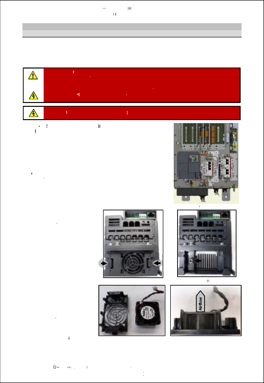
SBS
-
900 Shore
Ba
Ba
sed
Radar Systems
Chapter
10
10
:
Corrective maintenance
KH
KH
-
1602 2
issue 1
:
Standard SBS900 Systems Operator & Maintenance Handbook
Page
214
of
240
Fan
replacement
Health and safety notice
Fan replacement notes:
When used under normal operational conditions, the fan has an operational
life of 10 years and should only need replacing if it fails. Due to the drying of the electrolytic
capacitors, the entire inverter must be replaced every
10 years
.
WARNING:
Pr
Pr
ior to commencing any maintenance procedure, users must familiarise themselves
with the health & safety warnings noted in the planned maintenance and health and safety sections
of the system handbook.
Prior to carrying out planned maintenance, the system must be fully isolated and disconnected from
the single and 3
phase AC supplies. See
system isolation
in the planned maintenance section of
the system handbook.
Warning:
When the RDU is switched ON
lethal voltages are present within the inverter.
The VF
-
S1
S1
5
inverter is located with
in the
Radar Distribution
Unit (
RDU).
Repair:
The inverter is a sealed unit that contains
NO
NO
field
serviceable or repairable parts.
The unit must never be dismantled or
repaired in the field.
Inverter removal:
To replace the fan, the inverter will need
to
b
e removed from the radar distribution unit.
See section
9.6
page
100
for the inverter removal instructions.
Fan replacement:
When the inverter has been removed, the
fan can be accessed at the base of the unit.
Radar
distribution unit
Removal:
The fan assembly is
retained by two clips which are
released by pressing towards the
centre of the fan.
The fan assembly can now be
removed.
Disconnect the power connector
from the inverter.
Fan assembly removal
Fan
power
connection
Replacement:
Noting the
orientation and direction, the fan
can now be removed from the
plastic case and the replacement
fan fitted.
The fan is retained in the case
by 4 plastic clips.
The fan assembly can now be
reconnected/ refitted
and the
inverter replaced into the RDU.
Fan removed from case
Fan noting airflow direction
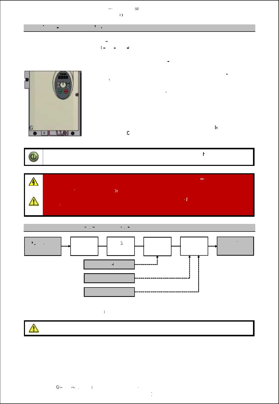
SBS
-
900 Shore
Ba
Ba
sed
Radar Systems
Chapter
10
10
:
Corrective maintenance
KH
KH
-
1602 2
issue 1
:
Standard SBS900 Systems Operator & Maintenance Handbook
Page
215
of
240
10.8.15
Three
-
phase inverter
VF
VF
-
S11
Manufactures part number:
VF
VF
-
S11
Kelvin Hughes part number:
45
45
-
690
-
0065
001
NOTICE: This part has been
superseded by the VF
-
S15 (see previous section)
The
Radar Distribution Unit
can be fitted with different
three
phase
inverter
s designed to meet the site AC requirements.
This converts the incoming three
-
phase supply into a voltage suitable
for the supply and control of the antenna motor.
The unit is also configured
to
provide a soft start and a soft stop for the
Motor.
For systems where a three phase supply is not availab
le
and optional
factory fitted 22
0VAC
single phase input kit is available.
Note:
With the exception of the user accessible and replaceable fan, t
he inverter is a
factory sealed unit that contains no field serviceable parts.
WARNING
:
Lethal voltages are present within the RDU and the three
-
phase inverter.
The system must be fully isolated from all sources of power prior to commencing any
inspection or
maintenance proc
edures.
Antenna rotation warning:
When AC voltages are applied to
the system, three phase
voltages are generated and the antenna WILL ROTATE even if no RUN command is
present.
Basic schematic for SBS
-
A1
A1
-
2 and SBS
-
A1
A1
-
3
The inverter voltage and speed is set during manufacture, apart from the tasks detailed in planned
maintenance, no operator action is
required for the inverter.
Caution:
Unauthorised adjustment of the inverter parameters can potentially damage the
antenna motor or stop the operation/ output of the inverter.
PL
PL
1:
3
-
phase
input
Filter and
indicator
6.0
A
breaker
Contactor
Motor
inverter
Safety I
loop
Antenna RPM control
Motor ON/ OFF control
SK4:
3
-
phase
output to
a
ntenna motor
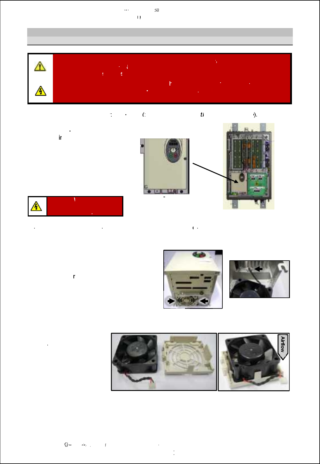
SBS
-
900 Shore
Ba
Ba
sed
Radar Systems
Chapter
10
10
:
Corrective maintenance
KH
KH
-
1602 2
issue 1
:
Standard SBS900 Systems Operator & Maintenance Handbook
Page
216
of
240
Fan
replacement
Health and safety
notice
WARNING
:
Prior to commencing any maintenance
procedure
, users must familiarise
themselves with the health
&
safety warnings noted in the planned maintenance
and
health and safety
section
s
of the system handbook.
Prior to carrying out
planned maintenance, t
he system must be
fully isolated and
disconnected
from the single and 3
-
phase AC supplies
. See
system isolation
in the
planned maintenance section of the system handbook.
Replacement fan part number
: NTX
-
A518 (
fan and cable but not t
he plastic enclosure
).
The Toshiba VF
-
S11 inverter is
located with
in the radar distribution
unit (RDU).
The inverter is a sealed unit that
contains no field serviceable or
repairable parts.
The unit must never be dismantled
or repaired in the field.
Toshiba VF
S11 inverter
Radar distribution unit
Warning:
When powered
lethal voltages are present
within the inverter
.
Inverter removal:
To replace the fan, the inverter will need to
b
e removed from the radar distribution
unit.
See section
9.6
page
100
for the inverter removal instructions.
When the inverter has been removed, the fan can
be accessed at the base of the unit.
The fan assembly is retained by two clips which
are released by p
ressing towards the centre of
the fan.
The fan assembly can now be removed.
Disconnect the power connector from the
inverter.
Fan assembly removal
Fan power disconnection
Noting the orientation and
direction, the fan can now be
removed from
the plastic
case and the replacement
fan fitted.
The fan is retained in the
case by 4 plastic clips.
The fan assembly can now
be reconnected/ refitted and
the inverter replaced into the
RDU.
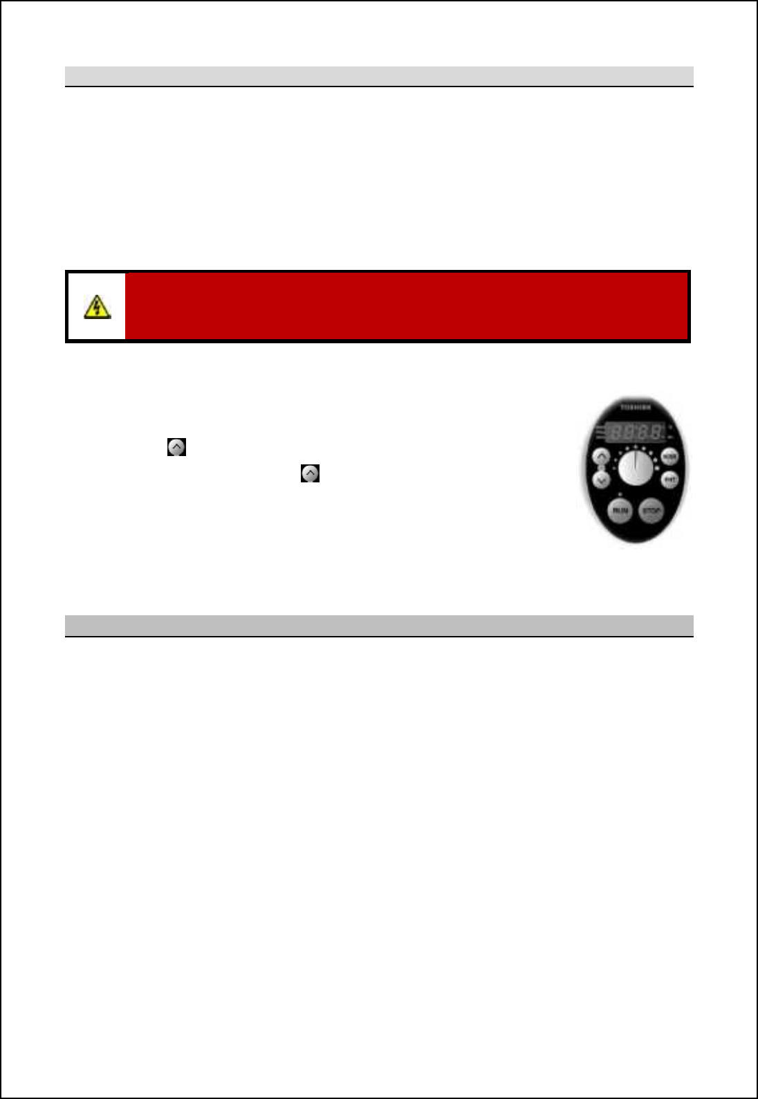
SBS-900 Shore Based Radar Systems
Chapter 10: Corrective maintenance
KH-1602-2 issue 1: Standard SBS900 Systems Operator & Maintenance Handbook
Page 217 of 240
Reset the fan run-time counter
When the fan has been replaced, the run time counter in the inverter must be reset to zero as follows:
Caution: The following task is carried out with the inverter switched ON and must must only be
undertaken by a qualified electrical engineer who understands the voltage hazards
present within the inverter and the Radar Distribution Unit.
Setup: The Radar Distribution Unit must be switched ON.
The Local/ Remote switch on the door of the RDU is set to Local.
The man aloft and antenna rotation switches are both in the FREE position.
WARNING: The following task is carried out with the Radar Distribution Unit switched ON
and powered. Lethal voltages are present within the unit so extreme care must be taken
when carrying out the adjustments detailed below.
I. On the inverter press the STOP button and wait until 0.0 is displayed.
This stops the inverter producing a three-phase output but single and
three-phase AC supplies are still present within the system.
II. Press the Mode button once, the PRG lamp will illuminate.
III. Press the button eight (8) times until typ is displayed.
IV. Press ENT once then press the button until menu 9is displayed.
V. Press ENT again. This reset the fan run-time counter to zero.
VI. Press MODE until 0.0 is displayed.
VII. Ensure the PRG lamp is no longer illuminated.
VIII.
Close and secure the RDU door then test the system
Inverter replacement
After 5-years of use, the static inverter located within the radar distribution unit must be changed as
over time, the electrolytic capacitors within the inverter can dry out.
The inverter replacement procedure is detailed in section 9.6 page 100 of Planned Maintenance.
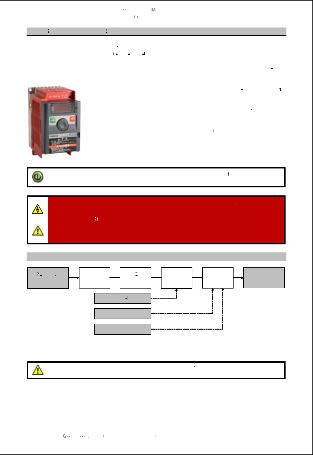
SBS
-
900 Shore
Ba
Ba
sed
Radar Systems
Chapter
10
10
:
Corrective maintenance
KH
KH
-
1602 2
issue 1
:
Standard SBS900 Systems Operator & Maintenance Handbook
Page
218
of
240
10.8.16
Single phase inverter
VF
VF
-
nC3
Manufactures part number:
VF
VF
-
nC3
Kelvin Hughes part number:
45
45
-
690
-
0066
001
An optional inverter is available that has a single phase AC voltage input. This is used where a 3
phase supply is not available on site.
The
Radar Distribution Unit
can be fitted with different
three
phase inverter
s
designed to meet the site AC
requirements.
This converts the incoming single phase AC supply into a three
-
phase
voltage suitable for the supply and control of the antenna motor.
The unit is also configured
to
provide a soft start
,
a soft stop for the Motor
and antenna speed selection
(system dependent)
.
The inverter is not a retro fit item and must be specified at the point of order.
Note:
With the exception of the user accessible and replaceable fan, t
he inverter is a
factory sealed unit that contains no field serviceable parts.
WARNING
:
Lethal voltages are present within the RDU and the inverter.
The system must
be fully isolated from all sources of power prior to commencing any inspection or
maintenance proc
edures.
Antenna rotation warning:
When AC voltages are applied,
three phase voltages are
generated and the antenna WILL ROTATE even if no RUN command is present.
Basic schematic
The inverter voltage and speed is set during manufacture, apart from the tasks detailed in planned
maintenance, no operator action is required for the inverter.
Caution:
Unauthorised adjustment of the inverter parameters can potentially damage the
antenna motor or stop the operation/ output of the inverter.
PL
PL
1:
Single
phase input
Filter and
indicator
6.0
A
breaker
Contactor
Motor
inverter
Safety I
loop
Antenna RPM control
Motor ON/ OFF control
SK4:
3
-
phase
output to
a
ntenna motor
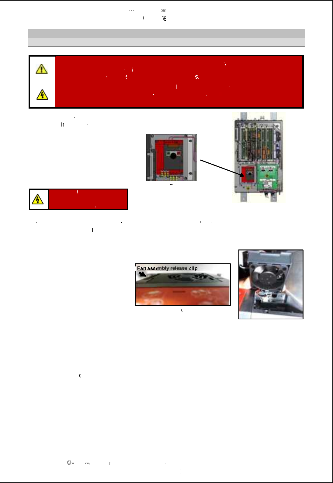
SBS
-
900 Shore
Ba
Ba
sed
Radar Systems
Chapter
10
10
:
Corr
ective maintenance
KH
KH
-
1602 2
issue 1
:
Standard SBS900 Systems Operator & Maintenance Handbook
Page
219
of
240
Fan
replacement
Health and safety notice
WARNING
:
Prior to
commencing any maintenance
procedure
, users must familiarise
themselves with the health
&
safety warnings noted in the planned maintenance
and
health and safety
section
s
of the system handbook
.
Prior to carrying out planned maintenance, t
he system must
be
fully isolated and
disconnected
from the single and 3
-
phase AC supplies
. See
system isolation
in the
planned maintenance section of the system handbook.
The Toshiba
VF
VF
-
nC3
inverter is
located with
in the Radar
Distribution Unit (RDU).
The inverter is
a sealed unit that,
with the exception of the fan,
contains no field serviceable or
repairable parts.
The unit must never be dismantled
or repaired in the field.
Toshiba VF
nC3
inverter
Radar distribution unit
Warning:
When powered
lethal voltages are present
within the inverter
.
Inverter removal:
To replace the fan, the inverter will need to
b
e removed from the Radar Distribution
Unit.
See section
9.6.2
page 107
for
the inverter removal instructions.
When the inverter has been
removed, the fan can be
accessed at
the top of the unit.
The fan assembly is retained by a
single clip which is released by
pressing towards the centre of the
fan.
The fan assembly can now be
removed.
Disconnect the power connector
from the inverter.
Fan assembly
on top of inverter
Fan power connection
Noting the orientation and direction, the fan can now be removed from the plastic case and the
replacement fan fitted.
The fan is retained in the case by 4 plastic clips.
The fan assembly
can now be reconnected/ refitted and the inverter replaced into the RDU.
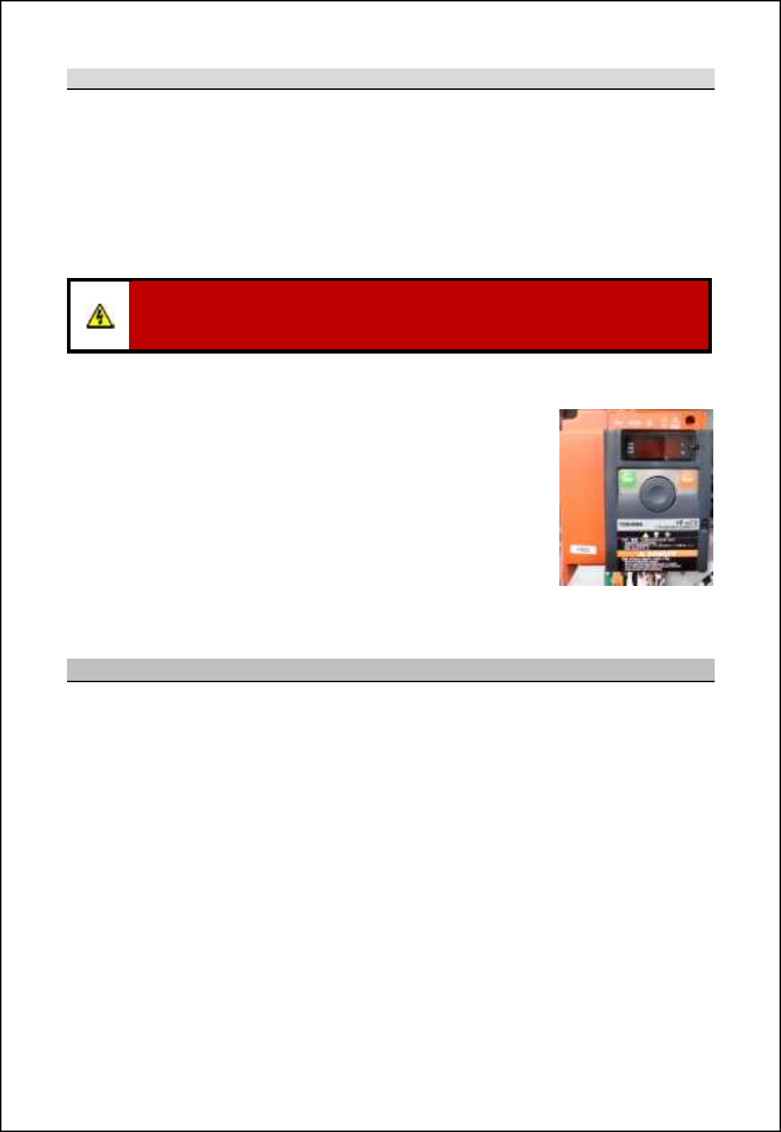
SBS-900 Shore Based Radar Systems
Chapter 10: Corrective maintenance
KH-1602-2 issue 1: Standard SBS900 Systems Operator & Maintenance Handbook
Page 220 of 240
Reset the fan run-time counter
When the fan has been replaced, the run time counter in the inverter must be reset to zero as follows:
Caution: The following task is carried out with the inverter switched ON and must only be
undertaken by a qualified electrical engineer who understands the voltage hazards
present within the inverter and the Radar Distribution Unit.
Setup: The Radar Distribution Unit must be switched ON.
The Local/ Remote switch on the door of the RDU is set to Local.
The man aloft and antenna rotation switches are both in the FREE position.
WARNING: The following task is carried out with the Radar Distribution Unit switched ON
and powered. Lethal voltages are present within the unit so extreme care must be taken
when carrying out the adjustments detailed below.
I. On the inverter press the STOP button and wait until 0.0 is
displayed. This stops the inverter producing a three-phase output but
single and three-phase AC supplies are still present within the
system.
II. Press the Mode button once, the PRG lamp will illuminate.
III. Rotate the thumbwheel until typ is displayed.
IV. Press the thumbwheel and again rotate the wheel until menu 9is
displayed.
V. Press ENT again. This reset the fan run-time counter to zero.
VI. Press MODE until 0.0 is displayed.
VII. Ensure the PRG lamp is no longer illuminated.
VIII.
Close and secure the RDU door then test the
system
Inverter replacement
After 5-years of use, the static inverter located within the radar distribution unit must be changed as
over time, the electrolytic capacitors within the inverter can dry out.
The inverter replacement procedure is detailed in the routine maintenance section 9.6.2 page 107.
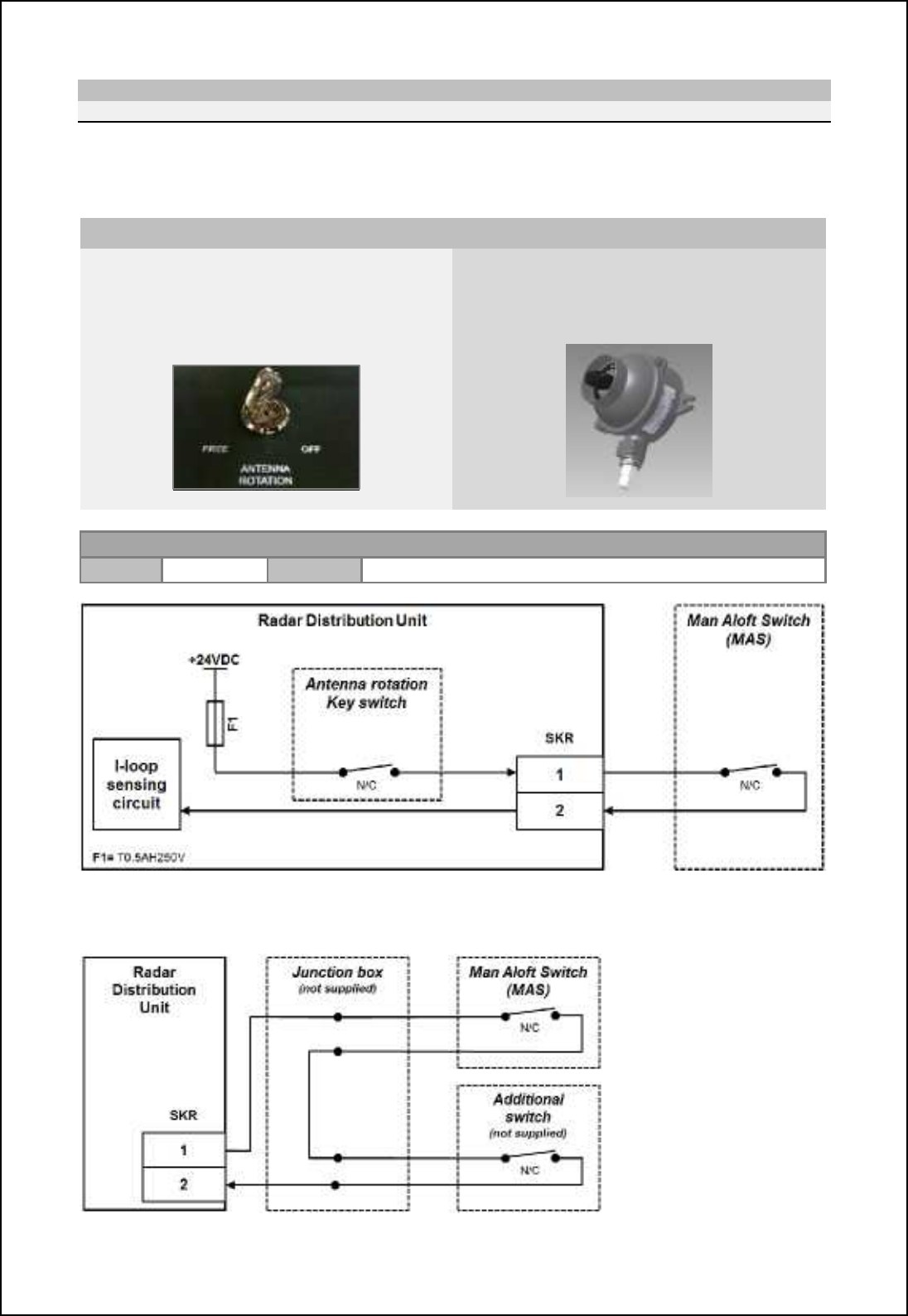
SBS-900 Shore Based Radar Systems
Chapter 10: Corrective maintenance
KH-1602-2 issue 1: Standard SBS900 Systems Operator & Maintenance Handbook
Page 221 of 240
10.8.17 Safety and security switches
Safety switches
The safety switches form part of a safety current I-loop. When either the Antenna Rotation or Man
Aloft switches are set to OFF or if the safety current loop is open, single and 3-phase AC supplies to
the transceiver/ gearbox are isolated thereby stopping antenna rotation and system transmission.
Antenna rotation Key switch Man aloft switch
The Antenna Rotation keyswitch is located on
the front door of the RDU.
This switch can be set to OFF and the key
removed and retained by the maintainer.
An externally mounted waterproof masthead
switch.
This switch can be set to FREE or OFF
Safety current loop: Serial connection of normally closed switches.
Polarity Positive Amplitude Fused (500mA anti-surge) +24V
Additional switches: The Antenna Rotation keyswitch and Man Aloft switch are provided as
standard however additional switches can be serially connected as shown:
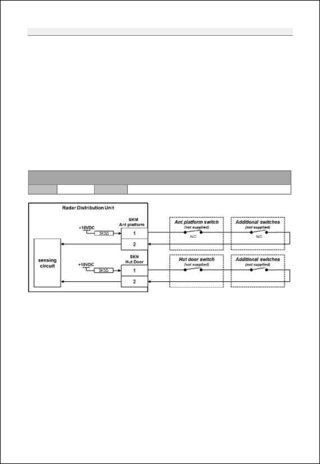
SBS-900 Shore Based Radar Systems
Chapter 10: Corrective maintenance
KH-1602-2 issue 1: Standard SBS900 Systems Operator & Maintenance Handbook
Page 222 of 240
Security switches
Connections are provided on the RDU for two security switches. The system reports the status of
these switches to the command and display system, track extractor or optional service display.
The normally closed (N/C) switch inputs switches are for monitoring purposes only and do not isolate
or control any aspect of the system.
Where fitted, these switches must be enabled during setting to work of the system.
Two switch connections are available as follows:
SKM / Ant Platform: This is designed for a security switch on the gate or access point to the
antenna platform.
SKN / Hut door: This is designed for a security switch on the equipment building or hut access
door.
Additional security switches can be serially added using a junction box (not supplied) in a similar
fashion to the security switches as shown on the previous page.
Antenna platform/ Hut door switch: Normally closed (N/C) switch returning a voltage back to
RDU.
Polarity Positive Amplitude *04U qcnb m_lc_m 2e2 ]oll_hn fcgcncha l_mcmnil

SBS-900 Shore Based Radar Systems
Chapter 10: Corrective maintenance
KH-1602-2 issue 1: Standard SBS900 Systems Operator & Maintenance Handbook
Page 223 of 240
10.8.18 Spares listings
SBS-A1-xx Radar Distribution Unit
Part number Description
VDR-A121-3 STATUS & ALARM PCA
85-200-0043-001 RELAY 2NO, DIN RAIL MOUNTED
45-6000-0118-001 LED GREEN, DIN RAIL MOUNTED
45-600-0102-001 MCB, DIN RAIL MOUNTED (10A)
45-600-0102-004 MCB 6A DIN RAIL 2 POLE S202-D6
40-666-2234 DIODE TYPE 1N4003
45-690-0080-001 DUAL PSU C-0204-090-240-7467-1
45-650-0060-009 FUSE CERAMIC 2.5A 5x20mm TIME LAG
NTX-A680 SIGNAL I/O MODULE (MISM 11)
NTX-A478 SERIAL COMMS MODULE (MISM 4 MK2)
NTX-A477-1 RADAR IO MODULE Mk2 ( MISM 9 )
NTX-A402-7 MODULAR INTERFACE SYSTEM BACKPLANE
NTX-1336 KEY SWITCH
45-600-0103-001 KEYSWITCH 2 WAY IP67
45-611-100 SWITCH SINGLE POLE ON/OFF TYPE 501
45-600-0101-001 SWITCH SPDT, IP67, ON-ON TOGGLE 20A
45-680-0140-001 MAINS FILTER 12A FN2080-12/06
45-680-0140-003 MAINS FILTER 6A TYPE FN2080-6-06
45-650-0060-002 FUSE CERAMIC 0.5A 5x20mm TIME LAG
45-825-0039-001 Fan 24VDC 80x80x38mm 8214J/2H4P
NTX-A462-101 Radar Processing Module (MISM-5) SX
NTX-A462-102 Radar Processing Module (MISM-5) FX
45-980-0039-003 SFP Transceiver (Single Mode)
45-825-0030-001 FAN 5V 35x35x10
55-100-0527-001 O Ring 22 X 2.5 FKM 80 (FP80 18 01)
SBS-A403: 440V Three Phase Inverter Kit
45-690-0084-002 INVERTER 3 PHASE 440V
NTX-A518 INVERTER COOLING ASSY
45-690-0065-002 FILTER 3-PHASE TYPE HLD 110-500/12
85-200-0044-001 CONTACTOR
45-6000-0118-001 LED GREEN, DIN RAIL MOUNTED
45-625-0657-001 THREE PHASE VOLTAGE INDICATOR
45-600-0102-002 MCB 6A DIN RAIL 3 POLE
40-666-2234 DIODE TYPE 1N4003
SBS-A229: 220V Single Phase Inverter Kit
45-690-0066-001 TRANSISTOR INVERTER
SBS-A405 VF-nC3 Inverter Fan Assy
45-680-0140-001 MAINS FILTER 12A TYPE FN2080-12/06
85-200-0044-001 CONTACTOR
45-6000-0118-001 LED GREEN, DIN RAIL MOUNTED
45-600-0102-001 MCB 10A DIN RAIL 2 POLE
40-666-2234 DIODE TYPE 1N4003
SBS-A404: 220V Three Phase Inverter Kit
45-690-0084-001 INVERTER 3 PHASE 240V
NTX-A518 INVERTER COOLING ASSY
45-690-0065-002 FILTER 3-PHASE TYPE HLD 110-500/12
85-200-0044-001 CONTACTOR
45-625-0657-001 THREE PHASE VOLTAGE INDICATOR
45-600-0102-002 MCB 6A DIN RAIL 3 POLE
40-666-2234 DIODE TYPE 1N4003
Additional
55-100-0436-001 STATIC DESSICATOR SD-003
SBS-A132 MAN ALOFT SWITCH (SBS)

SBS-900 Shore Based Radar Systems
Chapter 10: Corrective maintenance
KH-1602-2 issue 1: Standard SBS900 Systems Operator & Maintenance Handbook
Page 224 of 240
10.9 Alert messages
The following table lists the alarms that may be displayed on the LCD front panel of the Radar
Distribution Unit.
Alarm conditions can relate to individual equipment performance or be to report an issue with an
external input. An alarm on the system does not necessarily indicate a fault condition; the alarm may
be generated to alter the operator to a loss of signal, security switch status or an issue with the
system power.
RDU LCD
Message System status Description
Air Dryer Information warning only; no change
in system performance.
This is an indication of low pressure and/ or high
humidity in waveguide.
Antenna Platform
Open
Information warning only; no change
in system performance. The antenna Platform switch is open.
ARP/HL not
detected
Message received from SharpEyeTM
processor.
Antenna rotation and system
transmission will have stopped.
If an azimuth or heading line (HL) pulse is not
detected by the SharpEyeTM processor, a
message is sent to the transceiver and for safety
reasons transmission is stopped within 60
seconds.
Azimuth status (1)
Message received from SharpEyeTM
processor.
Antenna rotation and system
transmission will stop.
Antenna rotation is checked for clockwise rotation
(viewed from above). If anti-clockwise rotation is
detected, a message is sent and transmission is
stopped within 60 seconds.
Azimuth status (2)
Message received from SharpEyeTM
processor.
Antenna rotation and system
transmission will stop.
If missing pulses between heading lines are
detected, a message is sent and transmission is
stopped within 60 seconds.
Communication
Failure
The system will continue to operate
in its last configuration but cannot
be controlled.
Caution: The software Emergency
Stop function is disabled.
Communication has been lost with the track
extractor, command & display system or service
display. The system continues operation until
control is restored or the system is manually
switched to Local control.
Caution: When communication to the RDU is
lost, the Emergency Stop function on the track
extractor, command & display system or service
display will NOT function.
FPGA2 failed
Message received from SharpEyeTM
processor.
Antenna rotation and system
transmission will have stopped.
If the transceiver detects a hardware fault, it
sends a warning message to the display
equipment and switches to the Degraded state of
operation.
Hut Door Open Information warning only; no change
in system performance. The hut door switch is open.
Oil level low Information warning only; no change
in system performance.
The oil level in the CHL antenna gearbox is low
and should be inspected at the earliest safe
opportunity.

SBS-900 Shore Based Radar Systems
Chapter 10: Corrective maintenance
KH-1602-2 issue 1: Standard SBS900 Systems Operator & Maintenance Handbook
Page 225 of 240
RDU LCD
Message System status Description
Oil level
temperature
Information warning only; no change
in system performance.
The oil temperature in the CHL gearbox is high. At
the earliest safe opportunity, a general inspection
of the antenna should be made to see if there is
any reason for the elevated oil temperature.
The oil level should also be checked.
Over
temperature 1
Message received from
SharpEyeTM processor.
Transceiver switches to Low power
mode. See note below
If the temperature of the RF power transistors in
the transceiver exceeds predetermined limits, the
nl[hm]_cp_l m_h^m [h •ip_l-n_gj_l[nol_ q[lhcha ni
the Radar Distribution Unit and switches to the
^_al[^_^ fiq jiq_l mn[n_-
Over
temperature 2
Message received from
SharpEyeTM processor. Antenna
rotation and system transmission
will stop. See note below
If the temperature exceeds a further pre-set limit
the transceiver switches to the fault state and
transmission is stopped.
Over temperature notes: As the SharpEyeTM processor temperature returns to predetermined limits, the transceiver
returns to the degraded state and then to normal operation.
PSUA PWR
alarm
Depending on the fault condition the
system may operate normally or
antenna rotation and system
transmission may have stopped. See
note below
Indicates a fault condition with one half of the dual
redundant power supply within the RDU or a
problem with AC input A (PL2).
If the fault is with the power supply, the system will
operator normally using PSUB outputs.
If AC input A has failed or is lost, power to the
transceiver will also be lost stopping antenna
rotation and system transmission.
PSUB PWR
alarm
Information warning only; no change
in system performance. See note below
There is a fault with PSUB on the dual redundant
power supply within the RDU or a problem with the
AC input B (PL3).
The system will operator normally using PSUA
outputs.
PSU A or B PWR alarm notes: The cause of any power supply related alarms must be investigated at the earliest safe
opportunity and corrective action taken.
Safety current
I-loop open
Antenna rotation and system
transmission will have stopped.
The Safety current I loop is open.
Check that the Antenna Rotation, Man Aloft Switch
or any additional safety switches are in the FREE/
normally closed position.
Rx sensitivity
The system will be operational
however target detection may be
reduced.
If the minimum detectable signal rises above a pre-
set level the transceiver sends a receiver sensitivity
warning message.
Standby Antenna rotation and system
transmission will have stopped.
The system is in standby mode, ensure that no
fault conditions exist that could be preventing the
system entering Run mode.
SYNTH
Message received from SharpEyeTM
processor.
Antenna rotation and system
transmission will have stopped.
The SharpEyeTM processor synthesiser has not
initialised correctly. Cycling the power to the
transceiver may clear this condition.

SBS-900 Shore Based Radar Systems
Chapter 10: Corrective maintenance
KH-1602-2 issue 1: Standard SBS900 Systems Operator & Maintenance Handbook
Page 226 of 240
RDU LCD
Message System status Description
Tx power
Message received from SharpEyeTM
processor.
The transceiver will switch to Low
power mode (see below).
If the RF output power falls below 100W the
transceiver sends an RF Power LOW warning
g_mm[a_ [h^ mqcn]b_m ni nb_ ^_al[^_^ fiq jiq_l
state of operation.
Turning info lost
Message received from SharpEyeTM
processor.
Antenna rotation and system
transmission will have stopped.
If the antenna stops rotating when not commanded
to stop, a warning message is sent to the display
equipment and the transceiver switches to the fault
state (see below) and transmission is stopped.
VSWR
Message received from
SharpEyeTM processor.
The transceiver will switch to Low
Power or Fault mode.
If the VSWR on the RF output is worse than 1.4:1
the transceiver sends an antenna VSWR warning
g_mm[a_ [h^ mqcn]b_m ni nb_ ^_al[^_^ fiq jiq_l
state of operation (see below).
If the VSWR on the RF output is worse than 2.0:1
the transceiver enters fault mode (see below) and
is shutdown.
This can be an indication of a problem with the
SharpEyeTM processor, the connecting waveguide
or the antenna.
SharpEyeTM modes
In some of the alarm conditions noted above, the SharpEyeTM transceiver may enter one of the three
following states.
If any of these states is detected attempt a system reset. Should the fault condition persist please
contact Kelvin Hughes for further assistance.
Transceiver low
power mode
The transceiver continuously runs background performance checks on forward power,
reverse power, receiver sensitivity and temperature. If any of these parameters falls
outside predetermined levels a warning message is sent to the Radar Distribution Unit
indicating the nature of the fault.
The transceiver continues to operate, but with reduced performance and functionality.
Caution:As a result of reduced output power, range performance will be reduced and
the system may not meet the expected operational detection performance.
Transceiver fault
mode
If the performance or functionality is degraded such that the transceiver cannot operate
it enters the fault state and a fault message is sent to the display equipment.
The transceiver stops radiating RF and there is no video output to the Radar
Distribution Unit.
A spurious fault may be cleared by re-powering the equipment.
RDU to transceiver
communication
error
If communication is lost between the Radar Distribution Unit and the SharpEyeTM, the
RDU reboots the SharpEye leading to a potential 60 second gap in coverage.

SBS-900 Shore Based Radar Systems
Chapter 10: Corrective maintenance
KH-1602-2 issue 1: Standard SBS900 Systems Operator & Maintenance Handbook
Page 227 of 240
Page Intentionally blank

SBS-900 Shore Based Radar Systems
Chapter 11: Abreviations
KH-1602-2 issue 1: Standard SBS900 Systems Operator & Maintenance Handbook
Page 228 of 240
11 Abreviations
AC Alternating Current
ACH Anti-condensation heater
ACP
Azimuth Clock Pulse
AIS
Automatic Identification System
ARP
Azimuth Reset Pulse
BIT /
BITE Built In Test / Built in Test Equipment
CANBu
s
Controller Area Network Bus
CFAR
Constant false Alarm Rate
CW Continuous Wave
DC Direct Current
ECDIS Electronic Chart Display & Information System
EDPC
Enhanced Digital Pulse Compression
EM
Electromagnetic
EMC Electromagnetic Compatibility
EMCON Electromagnetic Control
ESM
Electronic Surveillance Measure
FAT
Factory Acceptance
Test
FCS
Fire Control System
FD Frequency Diversity
FSM Functional Status Message
GaN
Gallium Nitride
GPS
Global Positioning System
HL Heading Line
HRDPC High Resolution Digital Pulse
Compression
IALA International Association of Lighthouse
Authorities
IBS
Integrated Bridge System
IEC International Electrotechnical Committee
IF Intermediate Frequency
ILS
Integrated Logistic Support
IMO
International Maritime Organisation
I/O Input/ Output
IP Internet Protocol
IRS
Interface Requirement Specification
KH
Kelvin Hughes
KSD
Kelvin (Hughes) Software Document
LAN Local Area Network
LCD Liquid Crystal Display
LED
Light Emitting Diode
LNFE
Low Noise Front End
LPA Low Profile Antenna
LRU Line Replaceable Unit
m
Metre
MAC
Media Access Control
MAS
Man Aloft S
witch
MDP L[hn[Ccacn[fx Oli]_mmil
MDS Minimum Detectable Signal
MISM
Modular Interface System Module
MMI
Man Machine Interface
MTD Moving target Detection
MTTR Mean Time To Repair
nm
Nautical Mile
PC
Personal Computer
PCB
Printed Circuit Board
PRF Pulse Repetition Frequency
PWM Pulse Width Modulation
RAL
German Colour Standard
RACON
Radar Beacon
RDU
Radar Distribution Unit
RF Radio Frequency
RPM Revolutions Per Minute
Rx
Receive
SART
Search And Rescue Transponder
SBS
Shore Based Systems
SETD Systems Engineering Technical Document
STC Sensitivity Time Control
TBA
To Be Advised
TBC
To Be Confirmed
TCP
Transmission Control
Protocol
TFT Thin Film Transistor
nTrademark
Tx
Transmit
U
G_cabn ohcn i` 08 l[]e msmn_g
UDP
Universal Datagram Protocol
UPS Uninterruptable power supply
USB Universal Serial Bus
VSWR
Voltage Standing Wave Ratio
WAN
Wide Area Network
WI Work Instruction

SBS-900-11 Long Range Surveillance Shore Based Radar Systems
Chapter 11: Abreviations
KH-1611-2 operator & maintenance handbook issue 1
Page 229 of 240
Page Intentionally blank
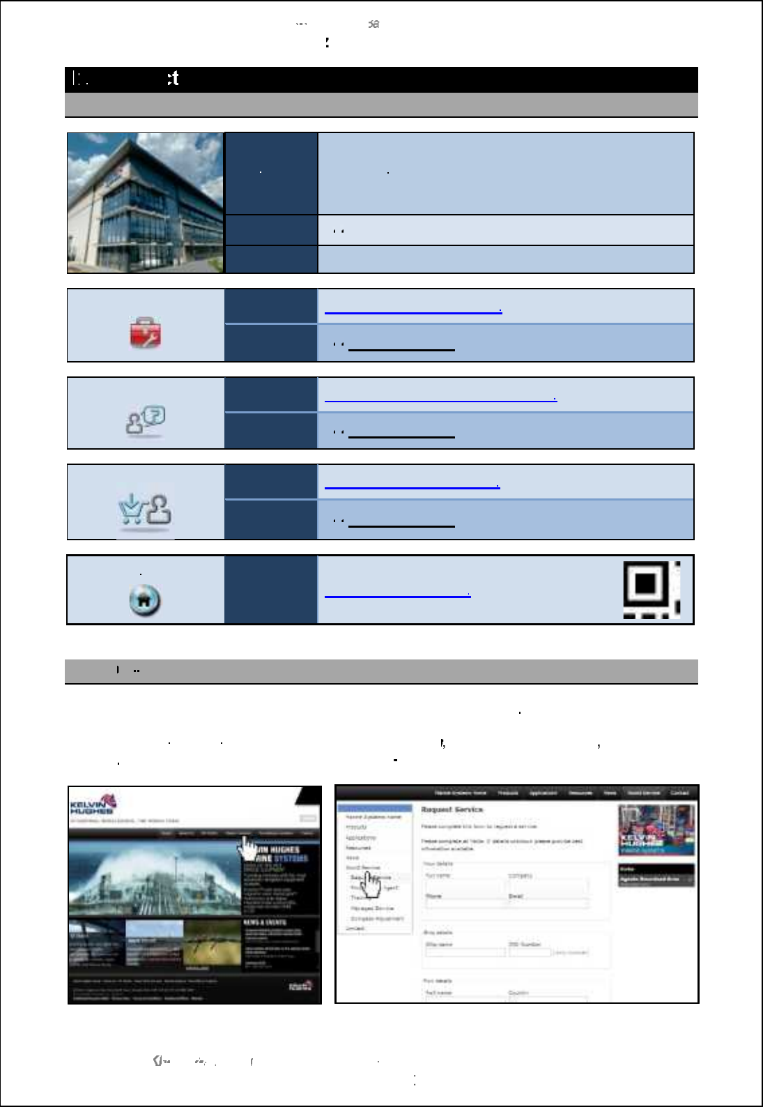
SBS
-
900 Shore
Ba
Ba
sed
Radar Systems
Chapter
12
12
:
Contacting Kelvin Hughes
KH
KH
-
1602 2
issue 1
:
Standard SBS900 Systems Operator & Maintenance Handbook
Page
230
of
240
12
12
Contac
ting Kelvin Hughes
12.1
Contact Kelvin Hughes
Address:
Kelvin Hughes Limited
Voltage
Mollison Avenue
Enfield, UK
EN3 7QX
Phone:
+
44
44
(0)1992 805 200
Fax:
+44 (0)1992 805 310
Service
email:
service@kelvinhughes.co.uk
Phone:
+
44
44
(0)1992 805 301
Technical advice
email:
technical.advice@kelvinhughes.co.uk
Phone:
+
44
44
(0)1992 805 302
Spares
email:
spares@kelvinhughes.co.uk
Phone:
+
44
44
(0)1992 805 301
Internet
Website:
www.kelvinhughes.com
www.kelvinhughes.com
12.2
On
On
-
line service request
A service request can be made via the Kelvin Hughes web site as follows
From the Kelvin Hughes web page
www.kelvinhughes.com
, select
Marine Systems
World
Service
,
Request
Service
and then complete the on
-
line form.

SBS-900 Shore Based Radar Systems
Chapter 12: Contacting Kelvin Hughes
KH-1602-2 issue 1: Standard SBS900 Systems Operator & Maintenance Handbook
Page 231 of 240
12.3 Kelvin Hughes regional offices
The following details the regional offices of Kelvin Hughes. A full list is also available in the Contact
tab of the Kelvin Hughes website @ www.kelvinhughes.com
Kelvin Hughes
Rotterdam, Netherlands BV
(GMT+1)
service@kelvinhughes.nl
Phone: +31 10 472 4050
Fax:
+31 10 472 4051
Kelvin Hughes A/S
Arhus, Denmark
(GMT+1)
service@kelvinhughes.dk
Phone: +45 8611 2888
Fax:
+45 8611 2260
Kelvin Hughes A/S
Bergen, Norway
(GMT+1)
service@kelvinhughes.dk
Phone: +45 8611 2888
Fax:
+45 8611 2260
Kelvin Hughes PTE Ltd
Singapore
(GMT+8)
service@khsing.com
Phone: +65 6545 9880
Fax: +65 6545 8892
Kelvin Hughes
Shanghai, China
(GMT+8)
service@kelvinhughes.cn
Phone: +86 21 58 772 105
Fax:
+86 21 58 785 944
Kelvin Hughes Limited
New Orleans, USA
(GMT-5)
usservice@kelvinhughes.com
Phone: +1 504 731 2999
Fax: +1 866 648 9763

SBS-900 Shore Based Radar Systems
Chapter 13: Annex A: RadarView software & service display control software
KH-1602-2 issue 1: Standard SBS900 Systems Operator & Maintenance Handbook
Page 232 of 240
13 Annex A: RadarView software & service display control
software
Printed copies In printed copies of this handbook, a copy of the RadarView user
manual can be found in this section.
Electronic
copies (PDF) In electronic copies, the RadarView user manual is can be found in
the root directory of the KH1601 document (PDF format).
Cambridge Pixel
RadarView
user manual
Details and copyright notice
SPx RadarView for Windows User Manual
Document number: CP-25-110-27
Kelvin Hughes Ltd is not responsible for the content of the
RadarView user manual which remains the copyright of Cambridge
Pixel Ltd.
Document reference CP-25-110-27 contains proprietary information that is
sensitive to the commercial interests of Cambridge Pixel Ltd. The contents
of this document should not be communicated to third parties without the
prior written consent of the Company.
Kelvin Hughes
Service display control
software.
Details on the Kelvin Hughes software that interfaces the optional
service display with the Radar Distribution Unit/ transceiver.

SBS-900 Shore Based Radar Systems
Chapter 13: Annex A: RadarView software & service display control software
KH-1602-2 issue 1: Standard SBS900 Systems Operator & Maintenance Handbook
Page 233 of 240
Page intentionally blank

SBS-900 Shore Based Radar Systems
Chapter 14: Annex B: Antenna sub system maintenance
KH-1602-2 issue 1: Standard SBS900 Systems Operator & Maintenance Handbook
Page 234 of 240
14 Annex B: Antenna sub system maintenance
ETahYTVgheXerf handbook: The SBS-900 series can be supplied with a range of Advanced
antennas.
The installation and maintenance instructions for these antennas and
the antenna turning unit (ATU) are detailed in a separate handbook
contained in this Annex.
The Antenna turning unit/ gearbox and antenna must be installed in
accordance with the manufactures requirements which include but
are not restricted to: Health and safety, unpacking, lifting and
installation requirements.
Handbook reference: Installation and Maintenance Manual
Radar Antenna System type KAH20-AS-00000

SBS-900 Shore Based Radar Systems
Chapter 14: Annex B: Antenna sub system maintenance
KH-1602-2 issue 1: Standard SBS900 Systems Operator & Maintenance Handbook
Page 235 of 240
Page intentionally blank

SBS-900 Shore Based Radar Systems
Chapter 15: Index
KH-1602-2 issue 1: Standard SBS900 Systems Operator & Maintenance Handbook
Page 236 of 240
15 Index
A
Abreviations ....................................................... 228
AC
Breaker type .................................................... 11
Breakers .......................................................... 30
Overview.......................................................... 11
AC supply isolation............................................... 87
Adverse weather - Checks after........................... 85
Alarms
Messages ...................................................... 224
Silence audio ................................................... 40
View alarm condition........................................ 40
Antenna
Advanced sub-system overview ...................... 26
Emergency STOP............................................ 43
Isolation ............................................................. 9
Lifting............................................................. 124
Radiation hazard................................................ 8
Rotates at switch on ........................................ 35
Rotation ON/ OFF switch on RDU ................. 221
Rotation safety notice .................................. 7, 35
S-band removal ............................................. 126
Standard sub-system overview........................ 25
X-band removal ............................................. 125
Anti-static handling............................................... 10
B
Brightness (RDU LCD)......................................... 65
Button functions (front panel) ............................... 39
C
CE marking ............................................................ 5
COMMS status menu........................................... 60
Contact details for Kelvin Hughes ...................... 230
Control menu
Detail ............................................................... 51
Overview.......................................................... 49
D
Default
Menu (RDU)..................................................... 64
Menu overview................................................. 50
Document history................................................... 6
Door removal...................................................... 123
DTX-A295 .......................................................... 149
DTX-A7 overview ................................................. 27
E
Earth bonding maintenance ............................... 120
Earth connections ................................................ 12
Electrical hazards................................................... 7
Emergency antenna stop......................................43
Emergency Stop
RadarView activation .......................................78
RadarView restart ............................................79
Enclosure menu ...................................................62
Encoder Replacement
S-band systems .............................................136
X-band systems .............................................130
End of life disposal ...............................................10
External commands..............................................69
F
Fan
Failure warning (RDU) ...........................113, 193
Replacement (RDU PSU) ..............................193
Replacement (VF-nC3 inverter) .....................219
Replacement (VF-S11 inverter) .....................216
Replacement (VF-S15 inverter) .....................214
Reset timer (VF-nC3 inverter)........................ 220
Reset timer (VF-S11 inverter) ........................217
Front panel
Buttons & control..............................................39
Overview & replacement ................................212
Fuse RDU...........................................................181
G
Gearbox oil...........................................................98
Grounding.............................................................12
H
Handbooks ...........................................................15
KH-1601-1 installation......................................15
KH-1601-2 operator .........................................15
RadarView .......................................................80
Health and safety warnings ....................................7
I
Interference rejection menu..................................54
Inverter
Control (VF-nC3)............................................109
VF-nC3 Single phase inverter........................218
VF-S11 Three phase inverter.........................215
VF-S15 Three phase......................................213
Isolating the system..............................................87
K
Kelvin Hughes
Contact details ...............................................230
Regional offices .............................................231

SBS-900 Shore Based Radar Systems
Chapter 15: Index
KH-1602-2 issue 1: Standard SBS900 Systems Operator & Maintenance Handbook
Page 237 of 240
L
LED RDU front panel ........................................... 36
Lifting
Antenna ......................................................... 124
S-band antenna supports .............................. 126
Local
Operational states............................................ 44
Operator instructions ....................................... 35
RDU controls ................................................... 36
Switch.............................................................. 37
Switch to Remote............................................. 46
M
Maintenance
10-year maintenance............................. 114, 117
3-year planed maintenance ............................. 98
5-year planned maintenance ......................... 100
Advacned antenna sub-systems...................... 86
Annual planned maintenance .......................... 88
Antenna & Gearbox ....................... 128, 134, 135
Earth bonding ................................................ 120
Planned ........................................................... 85
Man aloft switch ................................................. 221
Menu
Control menu ................................................... 51
Control menu overview.................................... 49
Default menu ................................................... 64
Navigation within menus.................................. 47
RDU menus..................................................... 47
Setup menu ..................................................... 64
Setup/ Default overview................................... 50
Status menu..................................................... 56
Status menu overview ..................................... 49
Microwave radiation levels ..................................... 8
MISM errors ......................................................... 61
MISM status menu ............................................... 61
Mute menu ........................................................... 53
N
Network
Menu (Default/ Setup)...................................... 66
Status menu..................................................... 59
NTP
Default/ Setup menu........................................ 66
Status menu..................................................... 60
NTX-A402 backplane......................................... 194
NTX-A462 Radar processing module................. 199
NTX-A477-1 radar I/O module ........................... 201
NTX-A478 serial comms module........................ 205
NTX-A490 signal I/O module ............................. 209
O
OP1, 2 & 3 Radar O/P menu................................ 66
Over current protection devices ........................... 11
Gearbox .........................................................122
RDU .......................................................180, 181
Transceiver enclosure......................................28
P
Part number
RDU ............................................................... 179
Transceiver enclosure....................................142
Planned maintenance
Advanced antenna sub-systems......................86
Standard antenna sub-systems ....................... 85
Power isolating the system...................................87
Power rating plate ................................................11
Power supply (RDU)
Fan replacement............................................193
Indicators .......................................................190
Overview........................................................189
Removal.........................................................191
Q
Quadrature converter PCB.................................149
R
Radar CNTRL defaults menu ...............................67
Radar Control Status menu..................................57
Radar Distribution Unit
Backplane ......................................................194
Breakers.........................................................182
Fuses .............................................................181
Overview..........................................................30
Power supply (AC-DC)...................................189
Radar I/O module...........................................201
Schematic ......................................................187
Serial Comms module....................................205
Signal I/O module...........................................209
Technical Overview........................................179
Radar Source menu .............................................51
RadarView
Emergency Stop...............................................78
Handbook.........................................................80
Manage radar menu.........................................81
Operator overview............................................80
Radiation hazards ..................................................8
Range Mode menu...............................................52
Rel Sector menu...................................................67
Remote
Operation .........................................................69
Operational states............................................70
Switch ..............................................................37
RoHS....................................................................10
Rotating joint removal
S-band systems .............................................138
X-band systems .............................................132
RPM menu ...........................................................55

SBS-900 Shore Based Radar Systems
Chapter 15: Index
KH-1602-2 issue 1: Standard SBS900 Systems Operator & Maintenance Handbook
Page 238 of 240
S
Safety aloft............................................................. 9
Safety switch...................................................... 221
Safety warnings...................................................... 7
S-band Processor removal & replacement......... 171
SBS-900-1 overview ............................................ 20
SBS-900-2 overview ............................................ 21
SBS-900-3 overview ............................................ 22
SBS-900-4 overview ............................................ 23
SBS-900-51 overview .......................................... 24
SBS-A126
Antenna power selection ............................... 154
Overview........................................................ 153
SBS-A3-2 service display..................................... 73
SBS-A3-3 service display..................................... 74
SBS-A3-5 service display..................................... 75
Sea & rain menu .................................................. 53
Security switch................................................... 222
Serial Ports menu................................................. 65
Service atendance ............................................. 230
Service display
Emergency stop............................................... 78
Overview.......................................................... 73
PC overview..................................................... 76
Reset ............................................................... 77
Switch ON/ OFF............................................... 77
Setup menu
Details.............................................................. 64
Overview.......................................................... 50
SharpEye menu ................................................... 58
Rb[ljDs_x _llil g_mm[a_m.............................. 163
Software info menu .............................................. 63
Software licensing................................................ 13
Spares listing
Advanced antenna sub-systems.................... 141
Approved spares.............................................. 85
RDU............................................................... 223
Standard S-band gearbox.............................. 135
Standard X-band gearbox.............................. 128
Transceiver enclosure ................................... 178
Static desiccator
Transceiver Enclosure................................... 177
Static inverter
Configuration/ settings................................... 104
Maintenance operation .................................. 103
Removal ................................ 101, 107, 114, 117
Status menu
Details.............................................................. 56
Overview.......................................................... 49
Sweep menu........................................................ 54
Switch
Antenna rotation.............................................221
Man Aloft Switch ............................................221
Safety.............................................................221
Security..........................................................222
Switching
OFF..................................................................42
OFF Emergency STOP....................................43
ON....................................................................41
System control overview.......................................32
System isolation ...................................................87
System overview ..................................................17
System status menu.............................................56
T
Three phase measurement ................................112
Transceiver
Enclosure overview..........................................27
Operational states............................................45
Transceiver enclosure
AC input .........................................................142
AC service socket ..........................................178
Internal illumination........................................178
Power supply unit(s).......................................147
S-band processor replacement ......................171
X-band processor replacement ......................165
Transceiver Enclosure
Static desiccator.............................................177
Transceiver operating states ................................71
TX Frequency menu.............................................53
TX Power menu....................................................52
U
Unit identification..................................................33
V
Variant Options menu...........................................65
VDR-A121-3 status and control PCB..................212
Virus protection ....................................................13
W
Waveguide switch...............................................174
Working aloft ..........................................................9
X
X-band Processor removal & replacement.........165

SBS-900 Shore Based Radar Systems
Chapter 15: Index
KH-1602-2 issue 1: Standard SBS900 Systems Operator & Maintenance Handbook
Page 239 of 240
Notes

SBS-900 Shore Based Radar Systems
Chapter 15: Index
KH-1602-2 issue 1: Standard SBS900 Systems Operator & Maintenance Handbook
Page 240 of 240
Kelvin Hughes Limited
Voltage, Mollison Avenue
Enfield EN3 7QX United Kingdom
t+44 (0)1992 805200
f+44 (0)1992 805310
www.kelvinhughes.com
UKVWCVKQPCN!KPVGNNKIGPEG-!VJG!YQTNF!QXGT!