Kenwood USA 219000 UHF FM portable Transceiver User Manual manual
Kenwood USA Corporation UHF FM portable Transceiver manual
UserManual.wiki
>
Kenwood USA
>
219000 User Manual
>
manual
Contents
1.
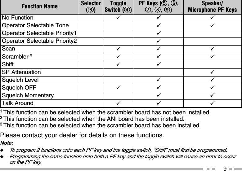
manual
2.
manual rf info
3.
RF safety information
manual
Navigation menu
Upload a User Manual
Namespaces
Wiki Guide
HTML
PDF
Info
Views
User Manual
Discussion / Help
Navigation