Kenwood USA 219000 UHF FM portable Transceiver User Manual manual
Kenwood USA Corporation UHF FM portable Transceiver manual
Contents
manual

INSTRUCTION MANUAL
KENWOOD CORPORATION
VHF FM TRANSCEIVER
TK-290
UHF FM TRANSCEIVER
TK-390
© B62-0816-30 (K)(MC)
09 08 07 06 05 04 03

i
THANK YOU!
We are grateful you chose KENWOOD
for your land mobile radio applications.
We believe this easy-to-use transceiver
will provide dependable
communications to keep personnel
operating at peak efficiency.
KENWOOD transceivers incorporate
the latest in advanced technology. As a
result, we feel strongly that you will be
pleased with the quality and features of
this product.
MODELS COVERED BY THIS
MANUAL
TK-290: VHF FM Transceiver
TK-390: UHF FM Transceiver
NOTICES TO THE USER
WARNING:
◆
GOVERNMENT LAW PROHIBITS THE
OPERATION OF UNLICENSED RADIO
TRANSMITTERS WITHIN THE
TERRITORIES UNDER GOVERNMENT
CONTROL.
◆
ILLEGAL OPERATION IS PUNISHABLE
BY FINE OR IMPRISONMENT OR BOTH.
◆
REFER SERVICE TO QUALIFIED
TECHNICIANS ONLY.
◆
DO NOT OPERATE YOUR
TRANSCEIVER IN EXPLOSIVE
ATMOSPHERES (GASES, DUST,
FUMES, ETC.).
◆
TURN OFF YOUR TRANSCEIVER
WHILE TAKING ON FUEL, OR WHILE
PARKED IN GASOLINE SERVICE
STATIONS.
SAFETY: It is important that the
operator is aware of, and understands,
hazards common to the operation of
any transceiver.

ii
One or more of the following
statements may be applicable:
FCC WARNING
This equipment generates or uses radio
frequency energy. Changes or modifications to
this equipment may cause harmful interference
unless the modifications are expressly approved
in the instruction manual. The user could lose
the authority to operate this equipment if an
unauthorized change or modification is made.
INFORMATION TO THE DIGITAL DEVICE
USER REQUIRED BY THE FCC
This equipment has been tested and found to
comply with the limits for a Class B digital
device, pursuant to Part 15 of the FCC Rules.
These limits are designed to provide reasonable
protection against harmful interference in a
residential installation.
This equipment generates, uses and can
generate radio frequency energy and, if not
installed and used in accordance with the
instructions, may cause harmful interference to
radio communications. However, there is no
guarantee that the interference will not occur in a
particular installation. If this equipment does
cause harmful interference to radio or television
reception, which can be determined by turning
the equipment off and on, the user is
encouraged to try to correct the interference by
one or more of the following measures:
•
Reorient or relocate the receiving antenna.
•
Increase the separation between the
equipment and receiver.
•
Connect the equipment to an outlet on a
circuit different from that to which the
receiver is connected.
•
Consult the dealer for technical assistance.
ATTENTION (U.S.A. Only):
The RBRC Recycle seal found on
KENWOOD
nickel-
cadmium (Ni-Cd) battery packs indicates
KENWOOD
’s
voluntary participation in an industry program to collect
and recycle Ni-Cd batteries after their operating life
has expired. The RBRC program is an alternative to
disposing Ni-Cd batteries with your regular refuse or
in municipal waste streams, which is illegal in some
areas.
For information on Ni-Cd battery
recycling in your area, call (toll free)
1-800-8-BATTERY (1-800-822-8837).
KENWOOD
’s involvement in this
program is part of our commitment to
preserve our environment and
conserve our natural resources.

iii
CONTENTS
UNPACKING AND CHECKING
EQUIPMENT ................................ 1
Supplied Accessories ................ 1
INSTALLING THE NiCd BATTERY PACK
(OPTIONAL) ................................ 2
INSTALLING THE ANTENNA (OPTIONAL) ...
3
INSTALLING THE CAP OVER THE
UNIVERSAL CONNECTOR ................ 3
INSTALLING THE BELT HOOK ............ 3
INSTALLING THE SPEAKER/
MICROPHONE (OPTIONAL) .............. 4
GETTING ACQUAINTED ................... 5
Key Descriptions ...................... 6
Display .................................. 7
PROGRAMMABLE FUNCTIONS .......... 8
BASIC OPERATIONS ...................... 10
Switching Power ON/OFF ........... 10
Adjusting the Volume................ 10
Selecting a Group ................... 10
Selecting a Channel ................. 11
Adjusting the Squelch ............... 11
Making a Call ......................... 11
KEY LOCK .................................. 12
TIME-OUT TIMER (TOT) ................. 12
SCANNING ................................. 12
Priority Scan .......................... 13
DTMF CALLING ........................... 13
Manual Dialing ....................... 13
Redialing .............................. 14
Auto Dialing ........................... 14
DEALER PROGRAMMABLE
OPTIONS ................................... 16
AUDIBLE USER FEEDBACK TONES .... 19
1
UNPACKING AND CHECKING
EQUIPMENT
Note:
The following unpacking instructions are for
use by your
KENWOOD
dealer, an authorized
KENWOOD
service facility, or the factory.
Carefully unpack the transceiver. We
recommend that you identify the items
listed in the following table before
discarding the packing material. If any
items have been damaged during
shipment, file a claim with the carrier
immediately.
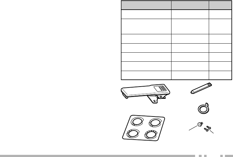
metI rebmuNtraP ytitnauQ
koohtleBXX-1560-92J1
lasrevinU
pacrotcennoc XX-3630-90B1
laeslennahCXX-4950-30B1
reppotslennahCXX-1240-23D1
teswercSXX-4002-99N1
dracytnarraW—1
launamnoitcurtsnIXX-6180-26B1
■Supplied Accessories
Channel stopper
Channel seal
Belt hook
Universal connector cap
Accessory
screw Binding
screws
Screw set
2
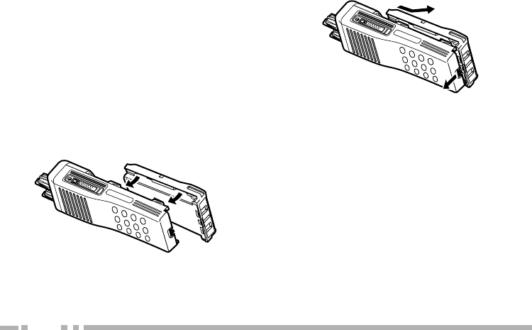
INSTALLING THE NiCd BATTERY
PACK (OPTIONAL)
The battery pack is not charged at the
factory. Charge the pack before use.
Repeat the charge/discharge cycles two
or three times after purchase or
extended storage (greater than
2 months) to bring the battery pack to
its normal operating capacity.
1Match the four grooves of the battery
pack with the corresponding guides
on the back of the transceiver.
2Slide the battery pack along the back
of the transceiver until the release
latch on the base of the transceiver
locks.
3To remove the battery pack, push
down on the release latch and slide
the pack away from the transceiver.
CAUTION:
◆
DO NOT RECHARGE THE BATTERY PACK IF
IT IS ALREADY FULLY CHARGED. DOING
THIS WILL OVERCHARGE THE BATTERY
PACK WHICH MAY SHORTEN ITS LIFE OR
DAMAGE IT.
◆
AFTER RECHARGING THE BATTERY PACK,
DISCONNECT IT FROM THE CHARGER. IF,
HAVING RECHARGED THE BATTERY, THE
POWER TO THE CHARGER IS TURNED OFF
AND THEN BACK ON WHILE THE PACK IS
STILL CONNECTED, RECHARGING WILL
START AGAIN AND THE BATTERY WILL
BECOME OVERCHARGED.
◆
DO NOT SHORT THE BATTERY PACK
TERMINALS OR DISPOSE OF THE BATTERY
BY FIRE. NEVER ATTEMPT TO REMOVE
THE CASE FROM THE BATTERY PACK.
3
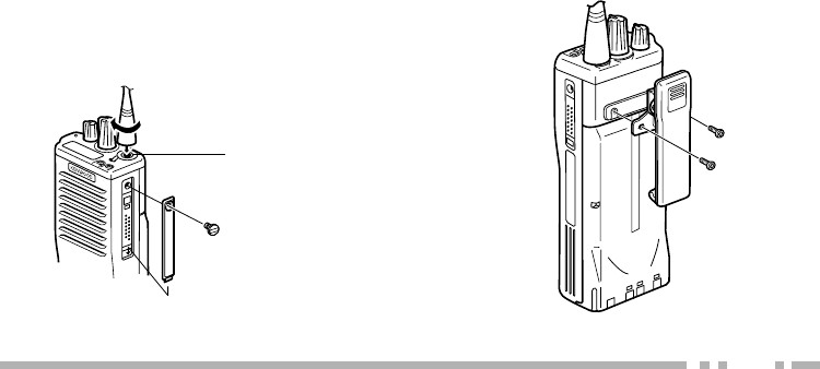
INSTALLING THE ANTENNA (OPTIONAL)
Screw the antenna into the connector
on the top of the transceiver by holding
the antenna at its base and turning it
clockwise until secure.
INSTALLING THE CAP OVER THE
UNIVERSAL CONNECTOR
When a speaker/microphone is not
being used, install the cap over the
universal connector using the supplied
accessory screw (4 x 6 mm).
Note:
To keep the transceiver water resistant, you
must cover the universal connector with the cap or
the speaker/microphone connector.
The antenna
connector of the
transceiver is an
SMA male type
connector.
INSTALLING THE BELT HOOK
If necessary, attach the belt hook using
the two binding screws (3 x 6 mm)
which are supplied in the screw set.
Note:
If the belt hook is not installed, its mounting
location may get hot during continuous
transmission or when left sitting in a hot
environment.
4
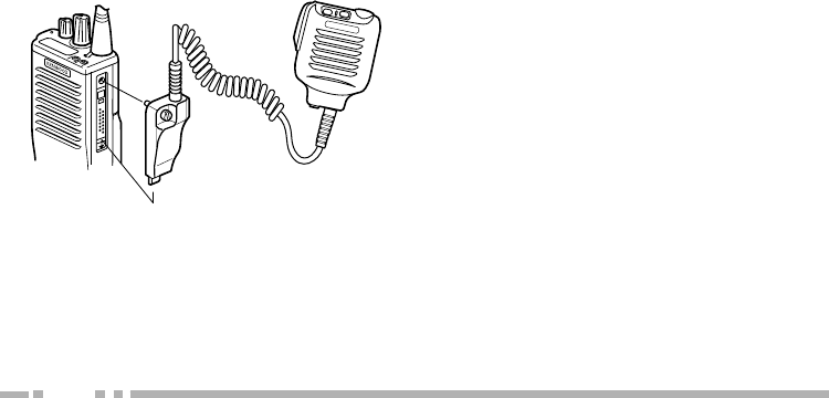
INSTALLING THE SPEAKER/
MICROPHONE (OPTIONAL)
1Insert the guide of the speaker/
microphone connector into the
groove on the transceiver universal
connector.
A speaker/microphone with an antenna
connector is also available.
2Secure the connector in place using
the attached screw.
Note:
The speaker/microphone PF keys can be
programmed with the functions listed in the table on
page 8.
5
AB
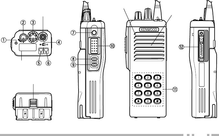
GETTING ACQUAINTED
SMA male type
antenna connector
Battery pack
release latch
Microphone
Speaker
Display

6
■Key Descriptions
qq
qq
qTX/Busy/Battery low indicator
Lights red while transmitting.
Lights green while receiving.
Flashes red when the battery
power is low while transmitting;
replace or recharge the battery.
Note:
This indicator can be disabled by
your dealer {page 16}.
ww
ww
wPower switch/Volume control
Turn clockwise to switch ON the
transceiver. Turn
counterclockwise, until a click
sounds, to switch OFF the
transceiver. Rotate to adjust the
volume level.
ee
ee
eSelector
Rotate this control to activate its
programmable function {page 8}.
Press these PF
(programmable
function) keys to
activate their
programmable
functions {page 8}.
rr
rr
rToggle switch
Switch the toggle position to
activate its programmable
function {page 8}.
tt
tt
tTop 1
yy
yy
yTop 2
uu
uu
uOrange
ii
ii
iSide 1
oo
oo
oSide 2
!0!0
!0!0
!0 PTT (Push-To-Talk) switch
Press this switch, then speak into
the microphone to call a station.
!1!1
!1!1
!1 DTMF keypad
(keypad models only)
Press the keys on the telephone
keypad to send DTMF tones.
!2!2
!2!2
!2 Universal connector
Connect the external speaker/
microphone (optional) here.
Otherwise, keep the supplied
cover in place.
7
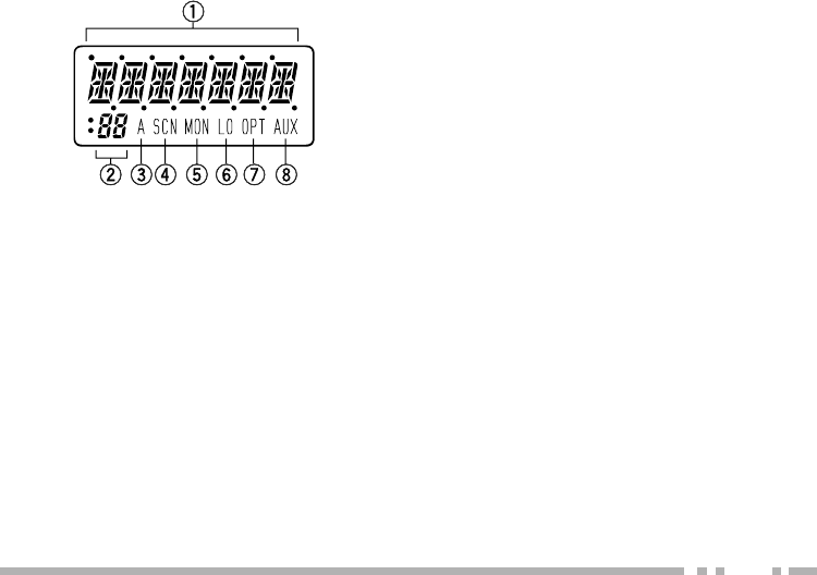
■Display
qq
qq
qAlphanumeric display
Displays the operating group or
channel number, or the group or
channel name. When making a
DTMF or 2 Tone call, the display
will alternate between CALL and
the channel. Also displays various
menu functions.
ww
ww
w7 Segment display
Displays the operating group or
channel number. Also displays
tA (Talk Around), P1 (Priority1),
P2 (Priority2), PP (Priority1 and
Priority2), or HC (Home
Channel); depending on the
function being used.
ee
ee
eA (Add) indicator
Appears when a channel is
added to the scanning sequence.
rr
rr
rSCN (Scan) indicator
Appears when Scan mode is active.
tt
tt
tMON (Monitor) indicator
Appears when the monitor
function is active.
yy
yy
yLO (Low) indicator
Appears when low power is
selected.
uu
uu
uOPT indicator
Appears when Operator
Selectable Tone is enabled.
ii
ii
iAUX (Auxiliary) indicator
Appears when Aux is ON.
Appears and blinks when the
optional scrambler board is
enabled.
Note:
The alphanumeric and 7 segment
displays can be inverted if a PF key or the
toggle switch is programmed with
Invert
Display
{page 8}.

8
PROGRAMMABLE FUNCTIONS
emaNnoitcnuF rotceleS
(ee
e
ee)
elggoT
(hctiwS rr
r
rr)
(syeKFP tt
t
tt,yy
y
yy,
uu
u
uu,ii
i
ii,oo
o
oo)
/rekaepS
syeKFPenohporciM
xuA
1
nwoDlennahC
emaNlennahC
tceleSlennahC
pUlennahC
ddA/eteleD
llaCycnegremE
2
nwoDpuorG
nacSpuorG
tceleSpuorG
pUpuorG
lennahCemoH
yalpsiDtrevnI
kcoLyeK
pmaL
rewoPwoL
rotinoM
yratnemoMrotinoM
9
1 This function can be selected when the scrambler board has not been installed.
2 This function can be selected when the ANI board has been installed.
3 This function can be selected when the scrambler board has been installed.
Please contact your dealer for details on these functions.
Note:
◆
To program 2 functions onto each PF key and the toggle switch, “Shift” must first be programmed.
◆
Programming the same function onto both a PF key and the toggle switch will cause an error to occur
on the PF key.
emaNnoitcnuF rotceleS
(ee
e
ee)
elggoT
(hctiwS rr
r
rr)
(syeKFP tt
t
tt,yy
y
yy,
uu
u
uu,ii
i
ii,oo
o
oo)
/rekaepS
syeKFPenohporciM
noitcnuFoN
enoTelbatceleSrotarepO
1ytiroirPelbatceleSrotarepO
2ytiroirPelbatceleSrotarepO
nacS
relbmarcS
3
tfihS
noitaunettAPS
leveLhcleuqS
FFOhcleuqS
yratnemoMhcleuqS
dnuorAklaT

10
BASIC OPERATIONS
■Switching Power ON/OFF
To switch ON the transceiver, turn
the Power switch/Volume control
clockwise until it clicks.
To switch OFF the transceiver, turn
the Power switch/Volume control
counterclockwise until it clicks.
If the Radio Password function is
programmed {page 16}, LOCKED
will appear on the display when the
power is turned ON. To unlock the
transceiver, enter the password, then
press the # key. If the wrong
password is entered, an error tone
will sound, and the transceiver will
remain locked. The password can
be a maximum of 6 digits. (This
function is available on keypad
models only.)
■Adjusting the Volume
Turn the Power switch/Volume
control to adjust the volume.
Clockwise increases the volume,
and counterclockwise decreases it.
■Selecting a Group
Turn the Selector, press the Group
Up and Group Down keys, or use
the toggle switch to select a group.
•Use the Selector, PF keys, or toggle
switch, depending on which one is
programmed with the group functions.

11
■Making a Call
1Select the desired group and
channel {page 10}.
2Use the key or switch
programmed as Monitor to check
whether or not the channel is
free.
•If the channel is busy, wait until it
becomes free.
3Press and hold the PTT switch,
then speak into the microphone
in your normal voice.
•For best results, hold the
transceiver approximately 3 to
4 cm (1 1/2 inches) from your lips.
4Release the PTT switch to
receive.
■Selecting a Channel
Turn the Selector or press the
Channel Up and Channel Down
keys to select a channel.
•Use the Selector or PF keys,
depending on which one is
programmed with the channel
functions.
■Adjusting the Squelch
1Press the key programmed as
Squelch Level.
2Press the keys programmed as
Group Up and Group Down or
Channel Up and Channel Down
to adjust the squelch level.

12
SCANNING
Note:
The Scan function can be used with a
minimum of two channels.
Scan is used to monitor signals on the
transceiver channels. When scanning,
the transceiver checks each channel for
a signal, and stops on a channel if one
is present.
Use the key or switch programmed as
Scan.
•“SCAN” or the revert group/channel
number (depending on which one is
programmed by your dealer), and the
SCN icon will appear on the display.
•A confirmation tone will sound.
To quit scanning, use the Scan key or
switch again.
•Two confirmation tones will sound.
KEY LOCK
Use the key or switch programmed as
Key Lock to activate the Key Lock
function. When activated, only the PTT
and toggle switch, the Selector, and
the keys programmed as Emergency
Call, Monitor, Monitor Momentary,
SP Attenuation, Squelch OFF,
Squelch Momentary, and Lamp can
be used.
TIME-OUT TIMER (TOT)
The TOT is used to automatically inhibit
transmission after a specified time
elapses. If the PTT switch is held down
for longer than the programmed time,
the transceiver will stop transmitting and
a warning tone will sound. To stop the
warning tone, release the PTT switch.
Note:
TOT settings can be programmed by your
dealer {page 16}.

13
DTMF CALLING
Note:
This function can only be used by
transceivers with DTMF keypads.
■Manual Dialing
To dial a number manually:
1Press and hold the PTT switch.
•If Keypad Auto PTT is enabled
{page 16}, you do not need to
press the PTT switch.
2Press the desired DTMF keys.
■Priority Scan
For Priority Scan to function, the
Priority1 or Priority2 channel must
be programmed.
•If only one of the priority channels are
programmed, the transceiver will
automatically change to that priority
channel when a signal is received on
it. This change occurs even if a
signal is being received on another
channel.
•If both priority channels are
programmed, Priority1 is the high
priority and Priority2 is the low
priority. If a signal is being received
on the Priority1 channel, the
transceiver will change to that
channel, even if a signal is being
received on the Priority2 channel.

14
■Auto Dialing
Note:
Auto dialing is either enabled or disabled
by your dealer {page 16}.
Store:
To store a number in memory:
1Press the # key.
•A “D” will appear on the display.
2Press the desired DTMF keys to
enter a maximum of 16 digits.
•Press and hold the PTT switch,
then press 2, 5, 8, 0, , or # to
enter A, B, C, D, , or #
(consecutively).
3Press the # key.
4Select the desired memory
channel by pressing a DTMF key
(1 ~ 9).
•The entered number will be stored
in the memory channel selected.
■Redialing
A maximum of 16 digits can be
redialed. The last number dialed,
either manually or automatically, will
be redialed.
To redial a number:
1Press the key.
•An “A” will appear on the display.
2Press the 0 key.
•The transceiver will redial the last
number, and the digits will appear
on the display.
Note:
If the transceiver power is switched OFF,
the redial memory will be erased.

15
Confirm:
To confirm a stored number:
1Press the # key.
•A “D” will appear on the display.
2Press the key.
•“D-” will appear on the display.
3Press the memory channel key
(1 ~ 9) with the stored number
you want to confirm.
•The stored digits will appear on
the display, and the DTMF tones
will sound.
Send:
To send a stored number:
1Press the key.
•An “A” will appear on the display.
2Press the memory channel key
(1 ~ 9) with the stored number
you want to send.
•The transceiver will begin the
transmission, and the digits will
appear on the display.
Clear:
To erase a stored number from
memory:
1Press the # key.
•A “D” will appear on the display.
2Press the # key again.
•“D-CLR” will appear on the
display.
3Press the memory channel key
(1 ~ 9) with the stored number
you want to erase.
16
DEALER PROGRAMMABLE OPTIONS
The following list of functions can be enabled or disabled by your dealer:
CHANNEL
Group Name
Receive Frequency
Transmit Frequency
QT/DQT Decode
QT/DQT Encode
Channel Name
Option Signaling
TX Power
Wide/Narrow
Scan Delete/Add
PTT ID
Busy Channel Lockout (BCL)
Beat Shift
Voice Scrambler
Priority1 Channel
Priority2 Channel
Home Channel
Emergency Channel
EDIT
Scan Information
Priority1
Priority2
Look Back Time A
Look Back Time B
Revert Channel
Dropout Delay Time
Dwell Time
Group Scan
17
Priority Channel Quick Scan
Priority1 Temp. D/A
Priority2 Temp. D/A
Temp. D/A Key Hold Time
Revert Channel Display
Optional Features
Channel Text Size
Group Text Size
Power ON Tone
Control Tone
Warning Tone
Alert Tone
Minimum Volume
Squelch Level
BCL Override
Selective Call Alert LED
Radio Password
Data Password
Battery Warning
Busy LED
TX LED
7 Segment LCD Display
Invert Display
Emergency Channel Display
Clear to Transpond
External Speaker
Noise Cancel Mic
Mode: Self Programming/Panel Test/
Clone/Main Programming
ID: ID Format/Speed/PTT ID/Dial ID/
Connect ID/Disconnect ID
Operator Selectable Tone: OST Back Up/
Direct OST/OST Name
Group Features
Time-out Timer (TOT)
TOT Pre-Alert
18
Please contact your dealer for details on these functions.
TOT Rekey Time
TOT Reset Time
Group Delete/Add
Battery Save
Signaling
2-Tone (1, 2, and 3)
Decoder Call Format (1 and 2)
Decoder Call Type (1 and 2)
Tones (A, B, and C)
Alert Tone/Transpond
Auto Reset
DTMF
DTMF Speed (Encode)
First Digit Time (Encode)
First Digit Delay (Encode)
and # Tone (Encode)
DTMF Side Tone (Encode)
DTMF Hold Time (Encode)
Keypad Auto PTT (Encode)
Manual Dial (Encode)
Auto Dial (Encode)
Auto Dial Programming (Encode)
Auto Dial Memory (Encode)
Alert Tone/Transpond (Decode)
Primary Code (Decode)
Secondary Code (Decode)
Auto Reset (Decode)
Dead Beat Disable (Decode)
Embedded Message
(64 characters maximum)

19
AUDIBLE USER FEEDBACK TONES
The transceiver outputs various tones to
indicate the transceiver operating
status.
•Power ON Tone
•Key Operation Tone
•End of Operation Tone
•Operation Error Tone
•Sequence Error Tone
•Transmission Inhibit Tone
•Time-out Timer Warning Tone
•Selective Call Alert Tone
•Call Alert (Transpond)
•Dead Beat Disable Tone
•Password Agreement Tone
Please contact your dealer for details
on these functions.
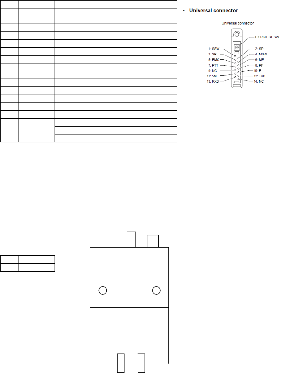
Terminal Descriptions
Universal connector
NO. Name Descri
p
tion
1SSW EXT/INT SP switch in
p
ut
2SP+ BTL out
p
ut + for external s
p
eake
r
3SP- BTL out
p
ut - for external s
p
eake
r
4MSW EXT/INT MIC switch in
p
ut
5EMC External micro
p
hone in
p
ut
6ME External micro
p
hone earth
7PTT PTT in
p
ut
8PF Pro
g
rammable function ke
y
in
p
ut
9NC Non connect
10 EMC Earth
11 5M 5V out
p
ut
12 TXD Serial data out
p
ut
13 RXD Serial data in
p
ut
14 NX Non connect
External RF out
p
ut
This terminal has a built in EXIT/INT
Non connect: INT ANT connect:EXT
Antenna Terminal
50 Ω impedance
Battery Terminal
The battery terminal uses a spring plate.
The negative terminal connects to the chassis ground.
The battery is mounted on the rear and upper side of the transceiver using a
sliding mounting method.
1+
2-
+ -
15
EXT OUT
Back side view
12
Radio FRequency eneRgy SaFety inFoRmation
This KENWOOD transceiver has been tested and complies with the standards listed below, in regards
to Radio Frequency (RF) energy and electromagnetic energy (EME) generated by the transceiver.
• FCC RF exposure limits for
Occupational Use Only
. RF Exposure limits adopted by the FCC are generally
based on recommendations from the National Council on Radiation Protection and Measurements, & the
American National Standards Institute.
• FCC OET Bulletin 65 Edition 97-01 Supplement C
• American National Standards Institute (C95.1 – 1992)
• American National Standards Institute (C95.3 – 1992)
This KENWOOD transceiver generates RF EME while transmitting. RF EME (Radio Frequency Electric &
Magnetic Energy) has the potential to cause slight thermal, or heating effects to any part of your body less
than the recommended distance from this radio transmitter’s antenna. RF energy exposure is determined
primarily by the distance to and the power of the transmitting device. In general, RF exposure is minimized
when the lowest possible power is used or transmission time is kept to the minimum required for consistent
communications, and the greatest distance possible from the antenna to the body is maintained. The
transceiver has been designed for and is classied for
Occupational Use Only
. Occupational/ controlled
exposure limits are applicable to situations in which persons are exposed to RF energy as a consequence
of their employment, and such persons have been made aware of the potential for exposure and can
exercise control over their exposure. This means you can use the transceiver only if you are aware of
the potential hazards of operating a transceiver and are familiar in ways to minimize these hazards. This
transceiver is not intended for use by the general public in uncontrolled environments. Uncontrolled
environment exposure limits are applicable to situations in which the general public may be exposed to RF
energy, or in which the persons who are exposed as a consequence of their employment may not be fully
aware of the potential for exposure or cannot exercise control over their exposure.
The following list provides you with the information required to ensure that you are aware of RF
exposure and of how to operate this transceiver so that the FCC RF exposure limitations are not
exceeded.
• While transmitting (holding the PTT switch or speaking with VOX enabled), always keep the antenna
and the radio at least 3 cm (1 3/16 inches) from your body or face, as well as from any bystanders. A
LED on the top of the radio shows red when the transmitter is operating in both PTT and VOX modes.
• Do not transmit for more than 50% of the total transceiver use time; transmitting over 50% of the total use
time may exceed the limits in accordance to the FCC RF exposure requirements. Nominal transceiver
operation is 5% transmission time, 5% reception time, and 90% stand-by time.
• Use only the specied antenna for this transceiver; this may be either the antenna provided with the
transceiver or another antenna authorized by KENWOOD.
Use only KENWOOD authorized accessories (antennas, battery packs, belt clips, Speaker/ Mics
or headsets etc.): When worn on the body, always place the radio in a KENWOOD recommended
clip or carrying case meant for this product. The use of other than recommended or approved
body- worn accessories may result in RF exposure levels which exceed the FCC’s occupational/
controlled environment RF exposure limits.
To ensure that your exposure to RF EME is within the FCC limits for occupational use, you must
observe and adhere to the above points.
Electromagnetic Interference Compatibility
Electronic devices are susceptible to electromagnetic interference (EMI) if they are not adequately
shielded or designed for electromagnetic compatibility. Because this transceiver generates RF
energy, it can cause interference to such equipment.
• Turn OFF your transceiver where signs are posted to do so. Hospitals and health care facilities use
equipment that is sensitive to electromagnetic radiation.
• Turn OFF your transceiver while on board an aircraft when so instructed. Use of the transceiver must
be in accordance with airline regulations and/or crew instructions.
B59-2448-00