Keyence 0945A Wireless Barcode scanner User Manual HR 51 Series E
Keyence Corporation Wireless Barcode scanner HR 51 Series E
Keyence >
Manual
Wireless
Hand-held Barcode Reader
HR-51 Series
User’s Manual
Read this manual before use in order to achieve maximum
performance.
Keep this manual in a safe place after reading so that you
can use it at any time.
Introduction
This manual contains information about procedures for handling, operations, warnings, and pre-
cautions about “Hand-held Barcode Reader HR-51 Series”.
Make sure to read this manual before use. Keep this manual in a safe place for future reference.
■Symbols
This manual uses the following symbols that alert you to important messages.
Be sure to read these messages carefully.
Indicates reference pages in this manual or other manuals.
■General Precautions
•At startup and during operation, be sure to monitor the functions and performance of
HR-51 and confirm the normal operation.
•We recommend that you take substantial safety measures to avoid any damage in the
event the HR-51 series malfunctions.
•If the product is modified or used in any way other than described in the specifications,
its functions and performance cannot be guaranteed.
•When the HR-51 series is used in combination with other devices, the functions and per-
formance may be degraded, depending on the operating conditions, surrounding envi-
ronment, etc..
•Do not use the HR-51 series for the purpose of protecting the human body.
■Notice
When this product is used under the circumstances and operating environments
described below, adhere to the limitations of the ratings, take adequate measures to
ensure safety such as fail-safe installations and consult a KEYENCE sales representative.
•For use under circumstances or environments which are not described in the manual.
•For use with nuclear power control, railway, aircraft, vehicles, incinerators, medical
equipment, entertainment equipment, safety devices, etc.
•For use in applications where death or serious property damage is possible and exten-
sive safety precautions are required.
DANGER Failure to follow instructions and mishandling the product may lead to death or
serious injury.
WARNING
Failure to follow instructions may lead to physical injury (i.e., electric shock,
burns, etc.).
CAUTION Failure to follow instructions may lead to the product malfunctions.
Note
Provides additional information on proper operations that can be easily mistaken.
1
Safety Precautions
■Safety Precautions on Laser Apparatus
The “Hand-held Barcode Reader HR-51 Series” employs a visible red semiconductor laser
for its light source. HR-51 has a wavelength of 650 nm and is classified as a Class 2 laser
under IEC standard (IEC60825-1: “Safety of Laser Products”).
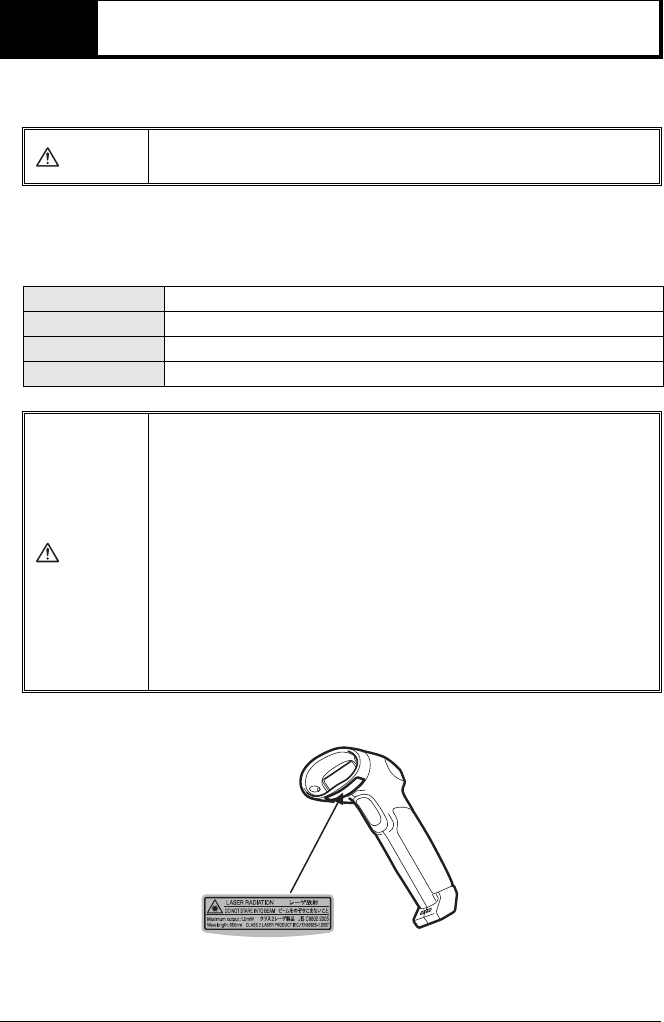
■Warning label locations
WARNING
Use of controls or adjustments or performunce of procedures other than those
specified herein may result in hazardous radiation exposure.
Model HR-51
Wavelength 650nm
Maximum output 1.0mW
Class CLASS 2 (IEC60825-1)
WARNING
•Do not directly stare into the laser beams or specularly reflected light. Doing
so may result in serious eye injury. Do not direct laser beams towards a human
body intentionally although laser beams will not cause damage even if it
strikes exposed skin.
•Never disassemble HR-51. HR-51 is not equipped with a mechanism to stop
laser emission when disassembled. If HR-51 is disassembled, laser beams
emitted from HR-51 may cause eye injury.
•Before cleaning the transmitter/receiver part of laser scanner, be sure to stop
the emission of laser beams. Otherwise, exposure to the laser may cause eye
injury.
•Be careful of the light path of laser beams.
Be especially careful of the specularly reflected light.
Do not install HR-51 in such a way that the laser beam passes at eye height
when operating HR-51.
HR-51

2
Operating Precautions
CAUTION
■Precautions on use
•Do not disassemble or modify this unit. Doing so may lead to product fail-
ure.
•This unit is a precision instrument. Dropping the unit or subjecting it to
shock may cause damage. Take enough care when carrying or using this
unit.
•Locate cables as far as possible from high-voltage lines and power lines.
Otherwise, generated noise may cause product failure or operation error.
•Do not hold the unit by its cable when carrying. The HR-51 may strike the
wall and may be damaged. Also due to the stress on the cables, the wires
may be broken.
•Be sure to use the supplied AC adaptor or optional AC adaptor for HR-
UC51. Using other AC adaptors than these may result in fire, electric shock
or product failures.
•Be sure to periodically clean the power connection part of AC adaptor con-
nected to HR-UC51 as it tends to catch dust. Tracking phenomenon may
result in fire. Also, disconnect the AC adaptor from the outlet if not using a
long period of time.
•When recharging HR-51 on HR-UC51, be sure to check no foreign objects
are attached to the recharge terminal. Foreign objects may cause fire.
■Environments for use
Do not use in the following locations. Product failure or mechanical error may
occur.
•Locations where the ambient temperature is beyond specified range
•Locations where the ambient humidity is beyond specified range
•Locations where the unit is exposed to direct sunlight
•High-temperature locations such as inside a closed car
•Locations where condensation occurs due to the rapid humidity change
•Locations where there are corrosive gas or combustible gas
•Locations where there is a large amount of airborne dust, salt, iron, and
greasy fumes
•Locations where the unit may be directly subjected to vibration or impact
•Locations where water, oil or chemicals may splash onto the unit
•Locations where a strong magnetic or electric field is generated
3
Precautions for using the built-in rechargeable battery
HR-51 contains the built-in lithium ion rechargeable battery. Observe the following precau-
tions for proper use.
On disposal, follow the disposal procedure specified by each local government.
DANGER
•Stop the recharging process if recharging does not finish even after the speci-
fied recharge time.
The built-in rechargeable battery may become hot, explode or cause fire.
•If there is leak or abnormal smell from the built-in rechargeable battery, keep it
away from fire immediately.
The battery electrolyte may catch fire, resulting in explosion and ignition.
•Never put it into the fire. The explosion of built-in rechargeable battery may
lead to a serious accident.
•Never put it into the water. The chemical reaction of the built-in rechargeable
battery may lead to an accident.
WARNING
•In the event that the leaked liquid comes into the eye, do not wipe it. Clean it
immediately with clean water instead and go to the eye specialist. If the eye is
left untreated, eye damage may result.
•In the event the liquid leaked from the built-in rechargeable battery is attached
to the skin, wash it immediately with clean water. Otherwise, skin irritation may
occur.
CAUTION
•Do not leave or use it in a heated car, under the scorching sun or at high-
humidity locations. The built-in rechargeable battery may become hot or cause
fire. Also, the battery life may become short and the performance may deterio-
rate.
•Recharge and use the built-in battery in the temperature environment of –5 to
140 degree. If it is used in other temperature environments than this, the built-
in rechargeable battery may be hot or damaged. Also, the life become short
and the performance may deteriorate.
•Never use other rechargers than the specified one. Product failure may occur.

4
Wireless communication
HR-51 and HR-UC51 contain the built-in wireless device based on the Bluetooth wireless
technology.
■Cautions for wireless communication
•If the product is used near a wireless LAN device with the same frequency band as that
of HR-51 and HR-UC51, radio wave interference may occur and the communication
speed becomes slow or communication may become impossible.
•The communication may be impossible near equipment using the same frequency band
of electric wave as that of HR-51 and HR-UC51, such as microwave oven, industrial
heating equipment and medical high-frequency equipment.
•Communication may be impossible in the following locations
- Locations near metallic objects or where there is much metallic powder
- Locations surrounded by a metallic wall
- Locations where the unit is subject to strong vibration
•Communication-possible distance is approx. 10 m, however, depending on the environ-
ment for use, communication may be impossible. Make sure to check the communica-
tion condition before introduction.
•With the frequency band for HR-51 and HR-UC51, premise radio stations (with license
required) and specified low power radio station (with license not required) for identifying
mobile objects used for industrial, scientific and medical equipment or product lines in
factory are operating.
•Before using HR-51 and HR-UC51, be sure to check that premise radio stations and
specified low power radio stations are not operating in the vicinity.
•If radio wave interference occurs from HR-51 and HR-UC51 against premise radio sta-
tions for identifying mobile objects, stop the electric wave generation, contact the follow-
ing address and consult to take necessary measures (i.e. setting a partition) to avoid
interference.
•If radio wave interference occur from HR-51 and HR-UC51 against specified low power
radio stations for identifying mobile objects or other problems occur, contact the follow-
ing address.
Contact address: KEYENCE CORPORATION, tel.:06-6379-1151
2.4 : This represents wireless equipment using
2.4GHz band.
FH : This represents the modulation method of
FH-SS.
1 : This represents the assumed interference
distance (≤ 10m)
: This represents the whole band is used and
the equipment range for identifying mobile
objects is unavoidable.
CAUTION
Never disassemble or modify HR-51 and HR-UC51 as those conducts are pro-
hibited by the Radio Law. HR-51 and HR-UC51 are regarded as specified low
power radio devices and they obtained Construction Design Certification
according to the standard required by law.
2.4 FH 1

5
Safety Regulations and Standards
■FDA regulations
HR-51 Series complies with FDA laser product regulation and is classified as class 2 laser
product.
Applicable regulation: 21 CFR Part 1040.10, 1040.11
The classification is based on IEC60825-1 following the Laser Notice No. 50 from FDA
(CDRH).
■FCC regulations
HR-51 Series complies with the following FCC regulations.
Applicable regulation : FCC Part 15 Subpart B, Class B digital devices
FCC Part 15 Subpart C
FCC ID : RF40945A (HR-51)
RF40945B (HR-UC51)
FCC WARNING
Changes or modifications not expressly apprvoed by the party responsible for compli-
ance could void the user’s authority to operate the equipment. This device complies with
Part 15 of the FCC Rules. Operation is subject to the following two conditions:
(1) this device may not cause harmful interference, and (2) this device must accept any
interference received, including interference that may cause undesired operation.
NOTICE
The HR-51 and the HR-UC51 have been tested and found to comply with the limits for a
Class B digital device, pursuant to part 15 of the FCC Rules. These limits are designed to
provide reasonable protection against harmful interference in a residential installation.
The HR-51 and the HR-UC51 generate, use and can radiate radio frequency energy and,
if not installed and used in accordance with the instructions, may cause harmful interfer-
ence to radio communications. However, there is no guarantee that interference will not
occur in a particular installation. If the HR-51 and the HR-UC51 do cause harmful interfer-
ence to radio or television reception, which can be determined by turning the equipment
off and on, the user is encouraged to try to correct the interference by one or more of the
following measures:
- Reorient or relocate the receiving antenna
- Increase the separation between the equipment and receiver.
- Connect the equipment into an outlet on a circuit different from that to which the receiver
is connected.
- Consult the dealer or an experienced radio/TV technician for help.

6
The HR-UC51 complied with FCC radiation exposure limits set forth for uncontrolled
equipment and meets the FCC radio frequency (RF) Exposure Guidelines in Supplement
C to OET65. The HR-UC51 has very low levels of RF energy that it deemed to comply
without maximum permissive exposure evaluation (MPE). But it is desirable that it should
be installed and operated with at least 20cm and more between the radiator and person’s
body (excluding extremities: hands, wrists, feet and legs).
The HR-51 complies with FCC radiation exposure limits set forth for uncontrolled equip-
ment and meets the FCC radio frequency (RF) Exposure Guidelines in Supplement C to
OET65. The HR-51 has very low levels of RF energy that it is deemed to comply without
testing of specific absorption ratio (SAR).
■CE Marking
HR-51 Series complies with the requirements of R&TTE Directive.
Applicable standards : ETSI EN300 328
ETSI EN301 489-1
ETSI EN301 489-17
EN60950-1
EN60825-1, Laser Class2
Overvoltage category : I (HR-51)
II (HR-UC51)
Pollution degree 2
■EU Countries where HR-51 Series can be used
HR-51 Series can be used in the following EU countries.
c Austria c Belgium c Cyprus c Czech
c Denmark c Estonia c Finland c France
c Germany c Greece c Hungary c Ireland
c Italy c Latvia c Lithuania c Luxemburg
c Malta c Holland c Portuguese c Slovakia
c Slovenia c Spain c Sweden c United Kingdom
c Poland c Bulgaria c Romania
7
Maintenance
Clean the following parts of HR-51 and HR-UC51 periodically.
•HR-51
Clean the transmitter/receiver and recharge terminal.
•HR-UC51
Clean the recharge terminal.
■How to clean
Transmitter/receiver : Wipe it lightly with an eyeglass cloth or a soft cloth moistened with a
plastic cleaner.
Recharge terminal : Wipe it lightly with a soft cloth moistened with alcohol.
Transmitter/receiver
Recharge terminal
Recharge terminal

8
MEMO

1-1
1
Overview
Overview
This chapter explains the package contents list, part names and
functions, and basic operations.
1-1 Checking the Package Contents. . . . . . . 1-2
1-2 Part Names and Functions . . . . . . . . . . . 1-5
1-3 Basic operations . . . . . . . . . . . . . . . . . . . 1-8
1-2
1
Overview
1-1 Checking the Package Contents
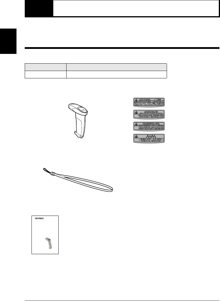
HR-51 comes with the following items. Check that all of the items are included.
Hand-held Laser Barcode Reader HR-51
■Main unit: 1
Model Communication interface
HR-51 Bluetooth interface
•HR-51 •Laser warning seal
•Strap
■User’s manual: 1
Japanese/English
German
French
Chinese
Wireless
Hand-held Barcode Reader
HR-51 Series
User’s Manual
Read this manual before use in order to achieve maximum
performance.
Keep this manual in a safe place after reading so that you
can use it at any time.
1-1 Checking the Package Contents
1-3
1
Overview
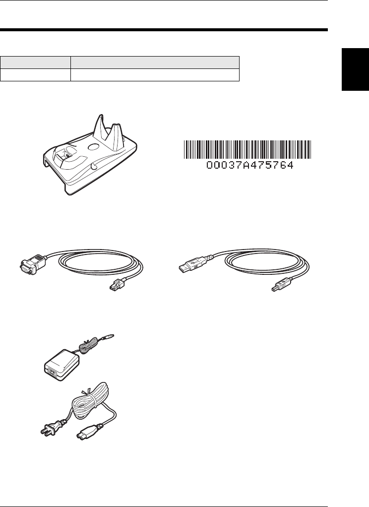
Communication unit HR-UC51 (Dedicated use for HR-51)
■Main unit: 1
Model Communication interface
HR-UC51 Bluetooth interface
•HR-UC51 •BD address barcode label
■Cables
•RS-232C cable •USB Cable
■AC adaptor: 1 ■Operating instructions: 1
1-1 Checking the Package Contents
1-4
1
Overview
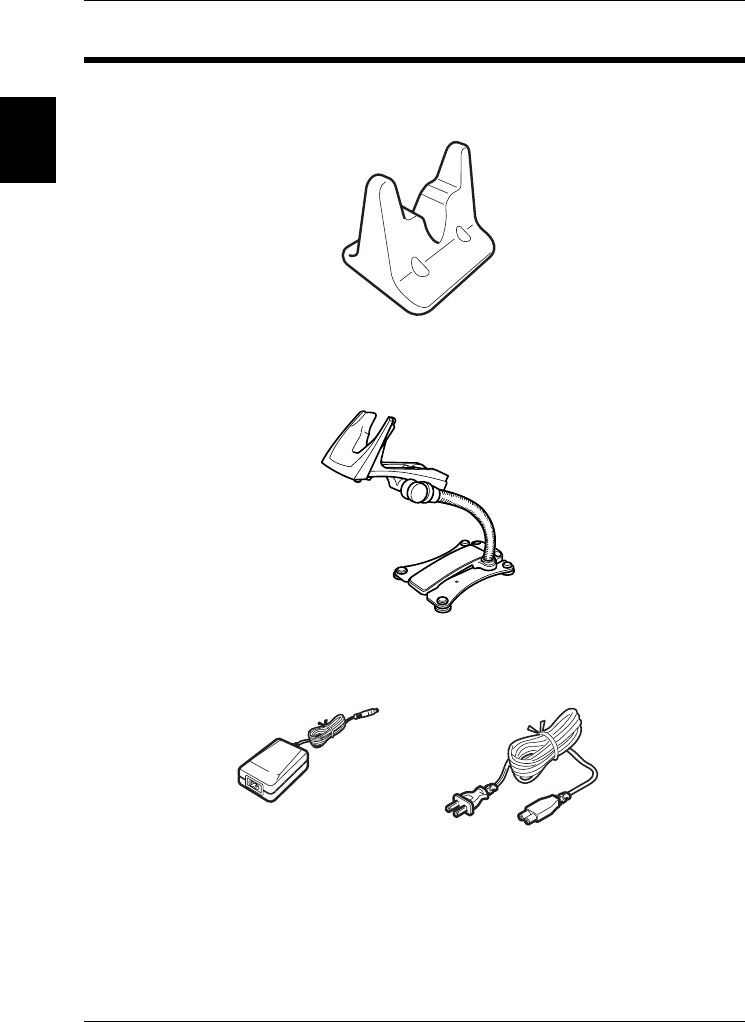
Options
■Stand OP-87027
•OP-87027: Use this stand when placing HR-51 on a table top
■Stand OP-87026
•
OP-87026
: Use this stand when using HR-51 in detection mode, etc.
■AC adaptor
•OP-84372: AC100 to 240V applicable (Same as the supplied accessory for HR-UC51)
1-5
1
Overview
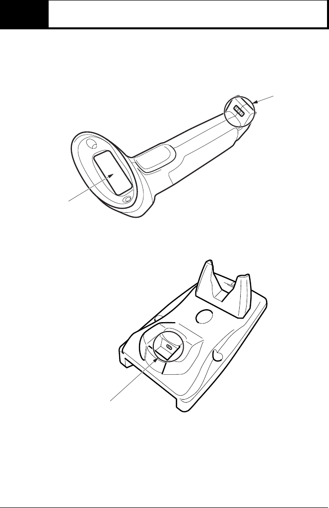
1-2 Part Names and Functions
This section explains the part names and functions
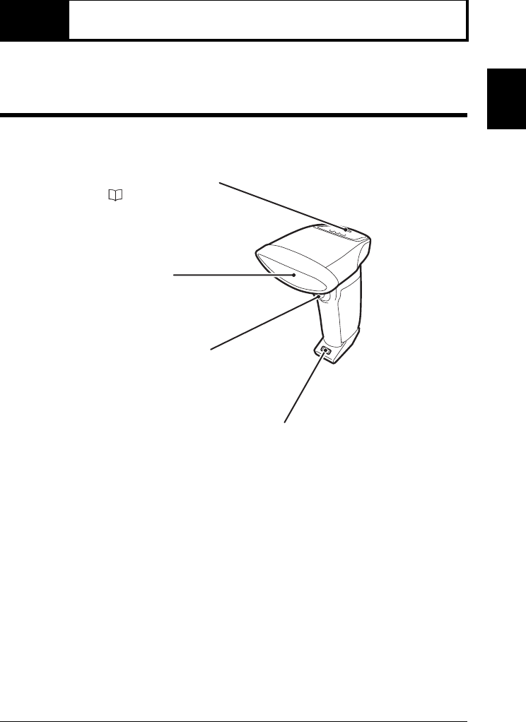
HR-51
Trigger switch:
Used when reading barcodes.
HR-51
Operation status LED:
( page 1-7)
Transmitter/receiver:
Emits laser beams and receives
the reflected light.
Recharge terminal
1-2 Part Names and Functions
1-6
1
Overview
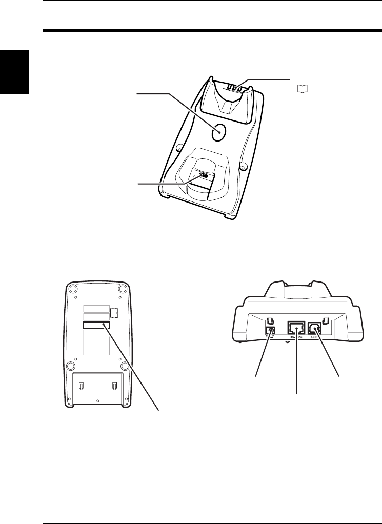
HR-UC51
HR-UC51: front
Operation status LED:
( page 1-7)
Reader search button:
Checks the connection of
HR-51 is established.
The paired HR-51 sounds a
buzzer.
Recharge terminal
bottom
BD address barcode
USB port
RS-232C port
Power terminal
back
1-2 Part Names and Functions
1-7
1
Overview
Operation status LED
■HR-51
■HR-UC51
LED color LED light-up timing
Green •When fully charged
•When recognizing barcode in program mode
Red
•When reading the Setup barcode that cannot be set
•When recharging
•When read data cannot be transmitted
Orange •When the remaining battery level is low
Blue
•When the connection with HR-UC51 is established
•When the transmission of read data is complete
•When scanning the Setup barcode
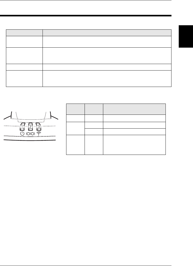
LED
number
LED
color LED light-up timing
➀Red When the power is turned on
➁Green When data transmission is complete
Red When data transmission is impossible
➂Blue
Lights up: When the connection with
HR-UC51 is established
Blinks: When the connection is
not yet established
1-8
1
Overview
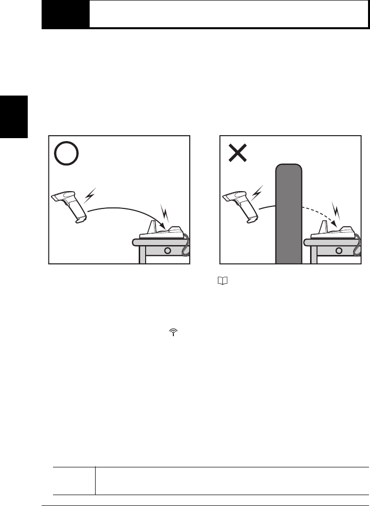
1-3 Basic operations
This section explains the basic operations of the barcode reader.
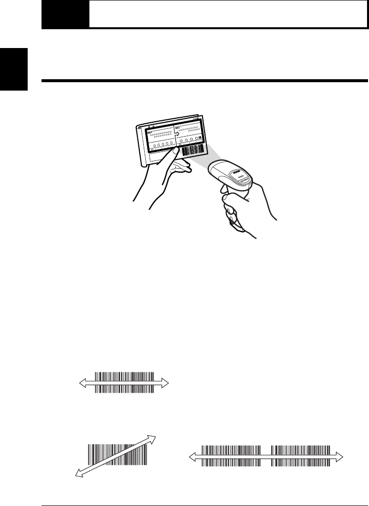
Reading a barcode
Point the transmitter/receiver toward the barcode and press the trigger switch about 50 mm
away from the barcode.
•When the barcode is read, the operation status LED (green) lights up and the buzzer
sounds.
(You can make the setting for the operation status LED and the buzzer not to operate.)
•The read barcode data is sent to the connected computer or other equipment.
■Notes for reading
Adjust the reading direction and reading timing so the laser beam can be emitted from the
one end to the other end of barcode to scan correctly.
•Correct scanning
•Wrong scanning
You cannot specify which barcode to read

2-1
2
Connections
Connections
This chapter explains the connection methods for HR-51 Series.
2-1 Connecting HR-51 to HR-UC51 . . . . . . . . 2-2
2-2 Connecting HR-UC51. . . . . . . . . . . . . . . . 2-4
2-3 Recharging HR-51 . . . . . . . . . . . . . . . . . . 2-7
2-4 Checking the connected pairs . . . . . . . . 2-9
2-5
Wireless communication environment
. . . 2-10
2-2
2
Connections
2-1 Connecting HR-51 to HR-UC51
HR-51 and the communication unit HR-UC51 communicate in pairs. Before operation, be
sure to establish the connection (pairing) between HR-51 and the communication unit HR-
UC51.
Procedure
1Press the “Trigger switch” to emit the laser beams.
2Select the communication interface.
(As a default setting, RS-232C interface has been selected.)
3Read the BD address barcode attached to the communication unit or supplied BD address
barcode.
Note •HR-51 operates in fully-charged condition.
•The communication unit HR-UC51 operates with the power ON.
Note
When the connection (pairing) is not established, the following operations or conditions
result.
•After the barcode is read, the operation status LED of HR-51 lights red once and the
buzzer sounds.
•LED ➂ of HR-UC51 blinks blue.
Perform the following operations in this condition.
•Note that even if you use more than 2 units of HR-51, communication is possible only
between connection-established HR-51 and the communication unit HR-UC51.
50mm

2-1 Connecting HR-51 to HR-UC51
2-3
2
Connections
When the connection (pairing) is established, the following conditions result.
•After the barcode is read, the operation status LED of HR-51 lights blue once and the
buzzer sounds.
•LED ➂ of HR-UC51 lights blue.
Notes when the wireless connection is established between HR-51 and HR-UC51
■For reading the barcode
You cannot read the barcode in the establishment process with HR-UC51.
■When multiple HR-51 and HR-UC 51 are connected
•Only connected pairs can communicate.
•If multiple HR-51 read the same address bar code of HR-UC51, only the first connec-
tion-established HR-51 can communicate with HR-UC51. If you wish to change pairs of
HR-51 and HR-UC51, perform the same operation as described at “Changing pairs of
HR-51 and HR-UC51” below.
■Changing pairs of HR-51 and HR-UC51
If you change HR-51 in use to another HR-51, perform the following operations.
Procedure
1Cancel the connection of connection-established HR-51 in either way of the following.
•Cut connection by reading the Connection-cut barcode.
•Cut connection by pressing and holding the trigger key.
•Cut connection automatically during wireless communication.
2Read the BD address of HR-UC51 using another HR-51.
CAUTION
If you change the communication interface, turn OFF and ON once and read the
BD address again. Otherwise, the unit may not operate normally (i.e. connection
failure, transmission failure).
Note If you restart HR-UC51, the connection of HR-UC51 will become unestablished. Make
sure to establish 1 to 1 connection between HR-51 and HR-UC51.
2-4
2
Connections
2-2 Connecting HR-UC51
After cables are connected, connect the communication unit to equipment with the connec-
tion method according to the communication interface.
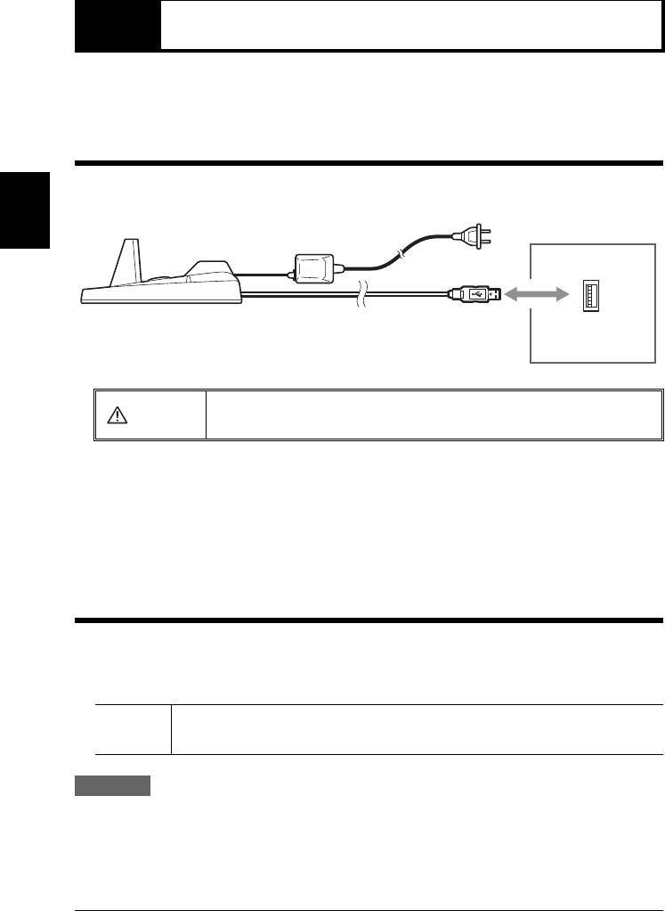
Connecting to a computer using the USB interface
Connect to the USB port of the computer. Compliant OS: Windows Vista/XP/2000/98
■Notes when using the computer
•Do not read a barcode while pressing down a key. Do not enter a key while receiving
data.
•Set the input mode to “half-width alphanumeric characters”.
•You can select keyboard specifications.
Installing the USB driver
When HR-UC51 is first connected to a Windows 98 PC, the USB driver installation screen
appears. Install the driver according to the on-screen instructions.
(Windows Vista, XP and 2000 do not require this operation.)
Procedure
1The “Add New Hardware Wizard” screen appears and the message “This window
searches for new drivers for: USB human interface device” is displayed. Click “Next”.
CAUTION Be sure to use the supplied AC adaptor or optional AC adaptor. Using other
power sources may damage the unit.
Note Connect the barcode reader after the startup of the computer. If it is connected with the
power OFF, start the computer.
To computer
USB port
(A type)
HR-UC51
2-2 Connecting HR-UC51
2-5
2
Connections
2The message “What do you want Windows to do?” is displayed. Then select “Search for
the best driver for your device (Recommended)” and click “Next”.
3Click on the “Next” button. “USB human interface device” is displayed and the message
“Windows driver file search for the device” appears. Click “Next”.
4Windows begins installing the driver. When installation is complete, the message “Win-
dows has finished installing the software that your new hardware device requires.” appears.
Click “Finish”.
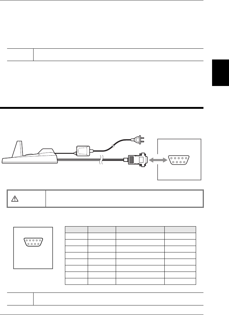
Connecting to a computer using the RS-232C interface
The barcode reader can directly connect to the serial port (RS-232C D-sub9 pin connector)
of a DOSV computer.
■HR-UC51 connector pin
Note The CD-ROM (Windows) may be required depending on the computer environment.
CAUTION Be sure to use the supplied AC adaptor or optional AC adaptor. Using other
power sources may damage the unit.
Note DR (DSR) and ER (DTR) functions cannot be used.
To computer
RS-232C
(D-sub9 pin)
HR-UC51
54321
9876
Pin number
Symbol Description
Signal direction
1 FG Frame Ground –
2 SD (TXD) Sends Data Output
3 RD (RXD) Receives Data Input
4 DR (DSR) Data set ready Input
5 SG Signal Ground –
6 – Do not connect. –
7 CS (CTS) Can Send Input
8 RS (RTS) Requests to send data Output
D-sub9 pin (female)
#4-40 screw
2-2 Connecting HR-UC51
2-6
2
Connections
■Communication settings
The default settings for HR-UC51 are as follows. The setting values can be changed.
Make sure that the settings for HR-UC51 and the connected computer are the same.
•Baud rate : 9600bit/s
•Data length : 7 bit
•Parity : Even
•Stop bit : 1 bit
•Communication protocol : Non-procedure
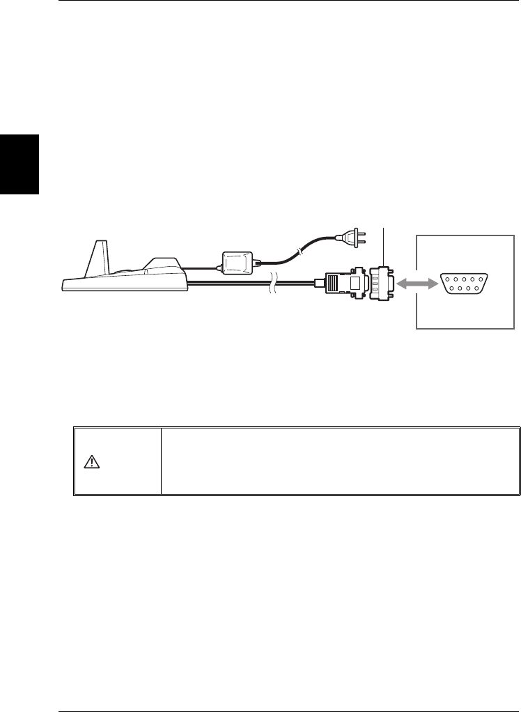
■Connecting to DV-90 Series
To connect to DV-90 Series, the conversion connecter is necessary as below.
Use the following conversion connector.
•Manufacturer : ELECOM Inc.
•Product name : Serial Reverse Adaptor
•Model : AD-R9
CAUTION
•Be sure to use the supplied AC adaptor or optional AC adaptor. Using other
power sources may result in fire, electric shock or product malfunctions.
•Power is supplied from the AC adaptor. Power is not supplied from the D-sub
connector.
DV90
RS-232C
Conversion Connecter
(D-sub9 pin)
HR-UC51
2-7
2
Connections
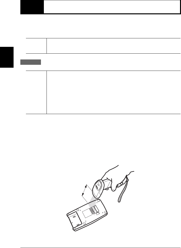
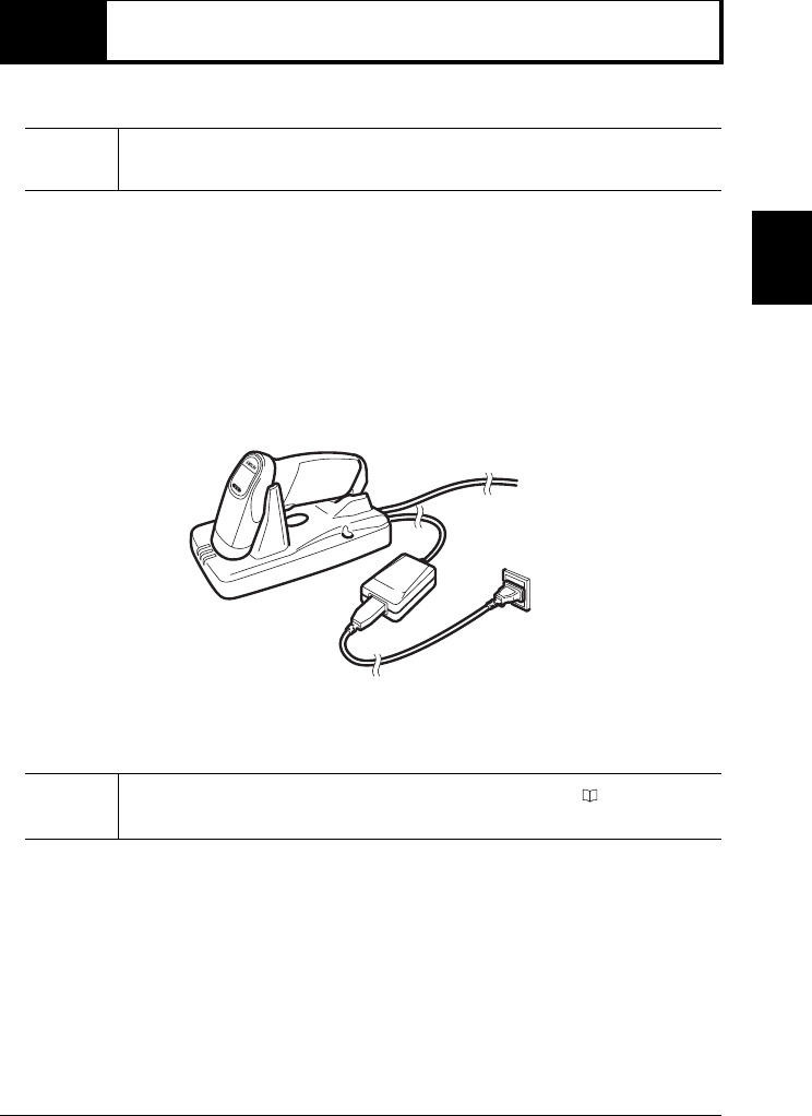
2-3 Recharging HR-51
Use the dedicated communication unit HR-UC51 to recharge HR-51.
■Recharge method
1Connect the supplied AC adaptor or optional AC adaptor to the communication unit HR-
UC51 and confirm the power is ON.
2Set HR-51 to the communication unit HR-UC51 so the recharge terminal of HR-UC51 is
not misaligned with that of HR-51.
As soon as recharging starts, the operation status LED of HR-51 lights red.
Recharging is complete when the operation status LED of HR-51 lights green.
Note There is no remaining battery at the time of shipment. Be sure to charge the battery
when using this product for the first time.
Note Clean the recharge terminals of HR-51 and HR-UC51 periodically ( page 7).
Dirt will interfere with recharging.
2-3 Recharging HR-51
2-8
2
Connections
HR-51 rechargeable battery
If the battery level of HR-51 becomes low, the operation status LED lights orange.
Pay attention to the operation status LED while operating and recharge the battery whenever
necessary.
■Continuous use time
The following chart shows approximate continuous use time in each case after recharging
HR-51 is complete.
*1 The battery is consumed even when not in use as HR-51 and HR-UC51 always communicates wirelessly.
•It is recommended that HR-51 is set on HR-UC51 when not in use.
■Recharge time
The following chart shows approximate recharge time from battery level 0 to fully-charged
level.
Conditions Approximate continuous use time
Reading 1 time/5 sec. 15 hours
Keeping the connection *1 16 hours
Wireless not connected 250 hours
Note
•The above continuous use time is approximate and may become shorter depending
on the period of use.
•If the continuous use time becomes extremely short, replace the battery. Consult
your nearest dealer.
Recharge method Recharge time
When power is supplied from the AC adaptor Approx. 3 hours
When power is supplied from the USB bus power Approx. 6 hours
2-9
2
Connections
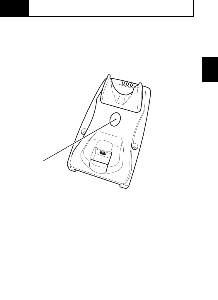
2-4 Checking the connected pairs
Checking the connection pairs may be necessary in the environment that multiple HR-51 and
the communication unit HR-UC51 are used. For example, when you are not sure which com-
munication unit is connection-established with HR-51, use this function.
■How to check the connected pairs
Press the “Reader search button” of the communication unit HR-UC51 while the connec-
tion between HR-51 and HR-UC51 has been established.
The paired HR-51 sounds a buzzer.
Reader search button
2-10
2
Connections
2-5 Wireless communication environment
Bluetooth Version 1.2 is used for the wireless communication between HR-51 and the com-
munication unit HR-UC51. Use in the following environment.
■Communication distance and surrounding environment
HR-51 and the communication unit HR-UC51 can communicate wirelessly within the
range of approx. 10 m.
However, the wireless communication is interrupted if obstacles such as concrete and a
metal exist. Use in environments with no obstacles.
Read “Cautions for wireless communication”. ( page 4)
■Operations when the wireless communication is interrupted
If the communication is cut, the following operations result.
•The operation status LED of HR-51 lights red once and the buzzer sounds.
•The operation status LED ➂ of communication unit HR-UC51 blinks.
When wireless communication becomes available, the setting is automatically restored
according to the setting contents of automatic reconnecting operation.
If connection fails within the automatic reconnecting operation period, make connection
again using either of the methods below.
•Read “Connection-ON barcode”.
•Read the readable barcode when “Automatic connection after reading the barcode”
is “Enable”.
•When “Connection on/cut by pressing down the trigger key” is “Enable”, press down
the trigger key for the set time for “Trigger key pressing-down time: Connection ON”.
• Read the BD address of HR-UC51.
Note If the BD address of UR-UC51 has not been registered on HR-51, read the BD address
of HR-UC51 before connection.
Obstacle

A-1
Appendix
Appendix
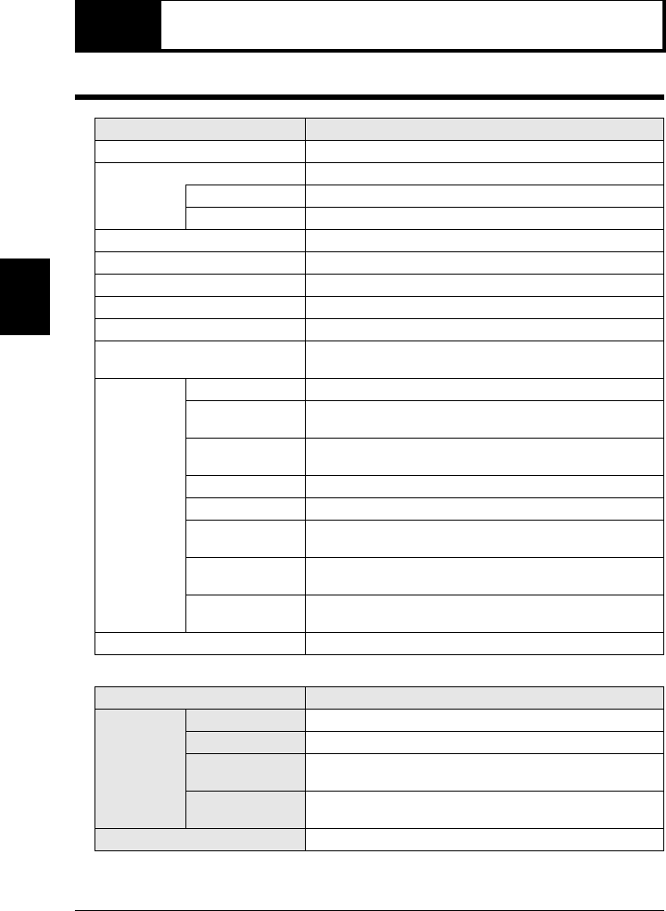
A-1 Specifications. . . . . . . . . . . . . . . . . . . . . . A-2
A-2 Dimensions. . . . . . . . . . . . . . . . . . . . . . . . A-5
A-2
Appendix
A-1 Specifications
HR-51 Series General specifications
Model HR-51
Interface Bluetooth communication type
Light source Visible red semiconductor laser (Wavelength: 650 nm)
Maximum output 1mW or less
Class CLASS 2 (IEC60825-1)
Reading distance See the characteristic range for reading (20 to 500 mm)
Reading width See the characteristic range for reading
Minimum resolution 0.127mm
PCS 0.45 or more
Scan rate 100 scans per second
Supported codes Code39, ITF, NW-7, JAN/EAN/UPC (add-on support), Code128,
GS1-128 (EAN-128), GS1 DataBar, Code93, Industrial 2of5
Environment
resistance
Drop impact 1.5m
Ambient
temperature –5 to +40°C
Storage ambient
temperature –20 to +60°C
Ambient light Sunlight: 50000 lx or less, fluorescent lamp: 3000 lx or less
Ambient humidity 5 to 95%RH, No condensation
Storage ambient
humidity 5 to 95%RH, No condensation
Operating
atmosphere No dust or corrosive gas present
Protection
structure IP42
Weight
Approx. 118 g
Model HR-51
Wireless
communication
part
Wireless standard Bluetooth Ver1.2
Wireless frequency
2402MHz to 2480MHz
Communication
output CLASS 2 (max. 2.5 m)
Communication
distance Scope 10m
Built-in battery Lithium ion battery, continuous use time: 16 hours
A-1 Specifications
A-3
Appendix
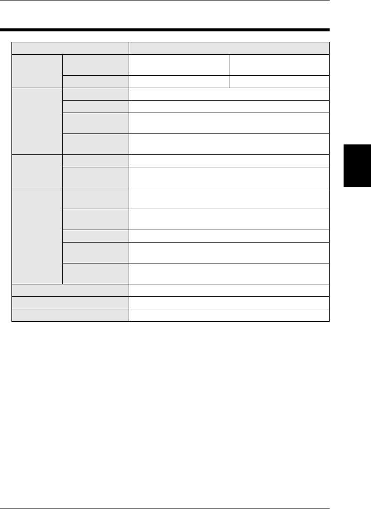
HR-UC51 General specifications (Communication unit dedicated for HR-51)
Model HR-UC51
Wired
communication
part
Communication
standard
USB Ver2.0 (HID class)
compliant RS-232C compliant
Connector shape USB (B type) D-sub9 pin (female)
Wireless
communication
part
Wireless standard Bluetooth Ver2.0
Wireless frequency
2402MHz to 2480MHz
Communication
output CLASS 2 (max. 2.5 m)
Communication
distance Scope 10m
Recharge
part
Recharge system Constant-current and constant-voltage system
Recharge time AC adaptor: approx. 3 hours
USB bus power: approx. 6 hours
Environment
resistance
Ambient
temperature –5 to +40°C
Storage ambient
temperature –20 to +60°C
Ambient humidity 25 to 85% RH, No freeze or condensation
Storage ambient
humidity 20 to 90% RH, No freeze or condensation
Operating
atmosphere No dust or corrosive gas present
Dimensions 78×100×185mm
Weight Approx. 230 g (excluding cables)
AC adaptor specifications See OP-84372 specifications.

A-1 Specifications
A-4
Appendix
■Interface specifications
USB interface
RS-232C interface
USB version USB-HID Fullspeed
Compliant OS Windows Vista/XP/2000/98
Format of sent data Same as data sent from keyboard
Synchronization method Start-stop synchronization
Transmission code ASCII code
Baud rate 600, 1200, 2400, 4800, 9600,
19200, 38400, 57600bit/s
Data length 7/8 bit
Parity check None/Even/Odd
Stop bit length 1/2 bit
Flow control Non
A-5
Appendix
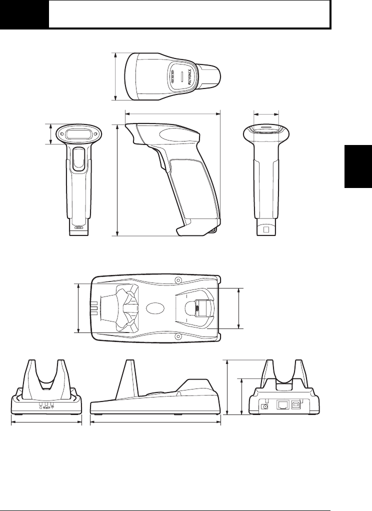
A-2 Dimensions
■HR-51 (Unit: mm)
■HR-UC51 (Unit: mm)
56
29
112.8
25
132
100
70 60
185
83
50
A-2 Dimensions
A-6
Appendix
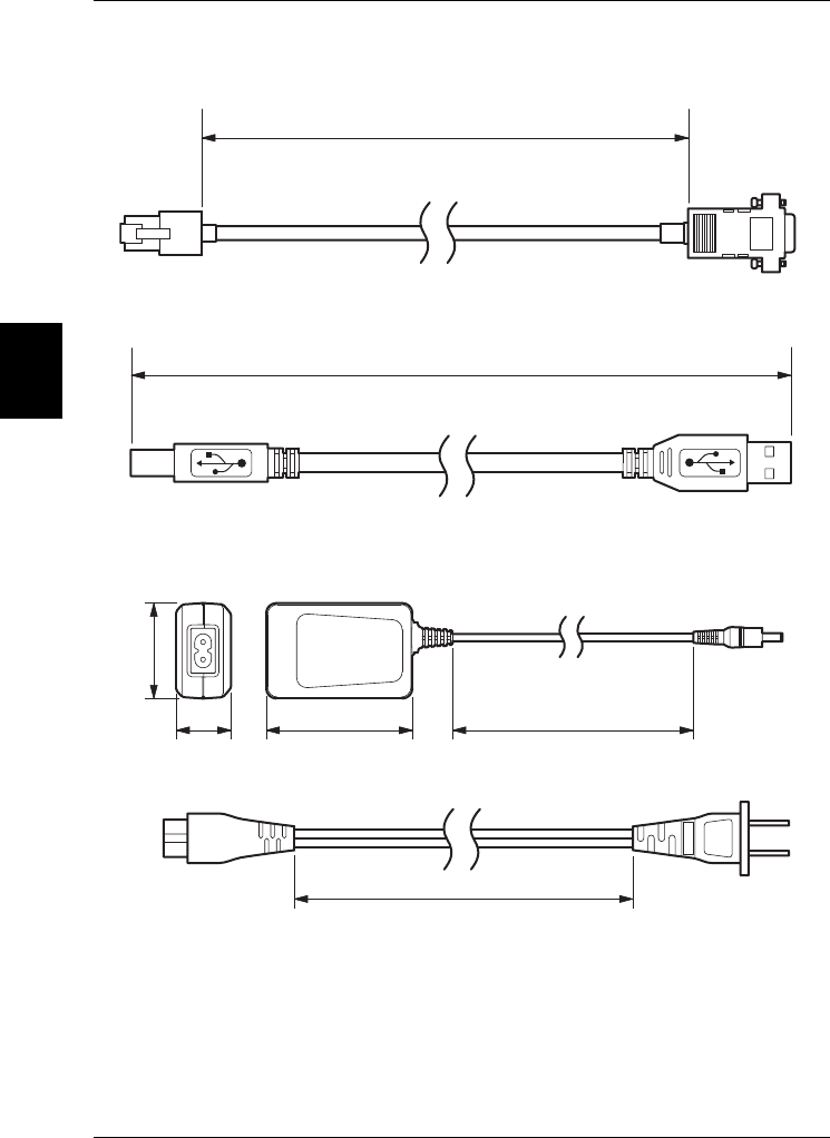
■Supplied cables
•RS-232C cable (Unit: mm)
•USB cable
■AC adaptor
•OP-84372 (supplied with HR-UC51) (Unit: mm)
1500
D-SUB9PIN
FEMALE
1500
USB-B connector USB-A connector
1800
1800
7227
47

A-2 Dimensions
A-7
Appendix
■Stand OP-87027
•OP-87027 (Unit: mm)
44.5 85
71 75
A-2 Dimensions
A-8
Appendix
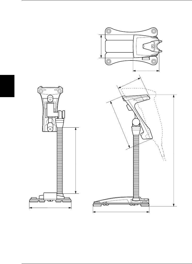
■Stand OP-87026
•OP-87026 (Unit: mm)
106
146
72
64
64
170
134
295

Warranty
1 Warranty period
One-year warranty is provided for this product after it is delivered to the designated place.
2 Warranty scope
(1) If failure occurs under KEYENCE responsibility during the above warranty period, free repair
service is provided.
However, the following cases are excluded from the warranty scope.
➀Malfunctions caused by improper conditions, environments, handling and operations
other than those described in the operating instructions, user’s manual and separately
provided specifications.
➁Malfunctions caused by user’s device or design contents of software except for
KEYENCE products.
➂Malfunctions caused by modification or service done by other parties than KEYENCE.
➃Malfunctions that could have been prevented if the consumable parts described in the
operating instructions or user’s manual had been properly maintained and replaced.
➄Malfunctions that were not foreseeable with the technology at the time of shipment.
➅Malfunctions caused by other external factors irrelevant to KEYENCE (i.e., fire, earth-
quake, flood, etc.)
The limit of warranty period is as described above (1). KEYENCE will not responsible for secondary
damages (device damage, opportunity loss, lost earnings, etc.) and any other damages on user’s
side resulted from malfunctions of KEYENCE products.
3 Applicable scope of product
KEYENCE products are designed and manufactured as general-purpose products for general
industrial use.
The following uses are not intended and are out of applicable scope.
However, if a user consults KEYENCE beforehand, confirms the product specifications under the
userfs responsibility, approves the rating and performance, and then take necessary safety mea-
sures, the use is applicable.
Even in this case, the warranty scope is the same as described above.
➀For use with facilities where death or serious property damage are possible, such as
nuclear power generation, aircraft, railway, ship, vehicles, medical equipment, etc.
➁For use with public facilities such as electricity, gas, water, etc.
➂For use outdoors and in similar conditions and environments
Copyright (c) 2009 KEYENCE CORPORATION. All rights reserved. Printed in Japan
KEYENCE CORPORATION OF AMERICA
50 Tice Blvd., Woodcliff Lake, NJ 07677 PHONE: 1-201-930-0100