King of Fans 52EWDS 52 inch Eastwind User Manual HDC 52in Eastwind ENG 11092015
King of Fans, Inc. 52 inch Eastwind HDC 52in Eastwind ENG 11092015
UserManual.wiki
>
King of Fans
>
52EWDS User Manual
User Manual
Navigation menu
Upload a User Manual
Namespaces
Wiki Guide
HTML
PDF
Info
Views
User Manual
Discussion / Help
Navigation
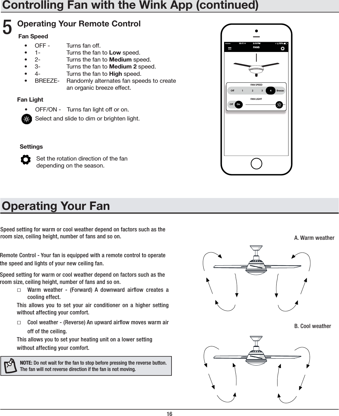
![15 HOMEDEPOT.COM/HOMEDECORATORSPlease contact 1-800-986-3460 for further assistance.Controlling Fan with the Wink AppDownloading the Wink Application1Connecting to the Wink HUB2Connecting to the Network3Ready to Control4 <ZPUN`V\YZTHY[KL]PJLUH]PNH[L[V[OLHWWSPJH[PVUZ[VYL(WWSL(WW:[VYLVY.VVNSL7SH`+V^USVHK[OLMYLL>052HWWHUKJYLH[LHUHJJV\U[CEILING FANCancel HelpBe sure your Hub is plugged in and within range of your fan. >P[O[OLHWWVWLUZLSLJ[¸HKKHWYVK\J[¹ *OVVZL[OL>PUR/<)HUKMVSSV^[OLPUZ[Y\J[PVUZVU[OLHWW >OLUPUZ[Y\J[LK[\YUVU`V\YMHUHUK3,++V^USPNO[6UJLWHPYPUNPZZ\JJLZZM\S[OLMHU^PSS[\YUVUH[SV^ZWLLKHUK[OLSPNO[^PSSISPUR[PTLZCEILING FANCancel HelpGreat, now you can turn on your fan. The light in your fan will blink 3 times when pairing is successful. 5V^[OH[[OLO\I»ZJVUULJ[LK`V\HYLYLHK`[VJVU[YVS`V\YMHUO 1 2 3 4 BreezeO OnFAN SPEEDFAN LIGHTFANS3:19 PM>P-P 53%56;,!Reset your fan if the pairing is taking longer than expected. Turn off your fan for 3 seconds, then turn it back on for 3 seconds. Repeat these steps 5 times. The light will blink 3 times when factory reset is successful. If pairing failed, please reset the device to original setting and re-start pairing.56;,!Be sure your Wink HUB is plugged in and within range of your fan.](https://usermanual.wiki/King-of-Fans/52EWDS/User-Guide-2812245-Page-15.png)

![15 HOMEDEPOT.COM/HOMEDECORATORSPara más asistencia, llama al 1-800-986-3460.Cómo controlar el ventilador con la app WINKCómo descargar la app WINK1Cómo conectarse al hub WINK2Cómo conectarse a la red3Listo para controlar4 *VU[\KPZWVZP[P]VPU[LSPNLU[LL_WSVYHSH[PLUKHKLSHHWSPJHJP}U(WWSL(WW:[VYLV.VVNSL7SH`+LZJHYNHSHHWW>052NYH[PZ`JYLH\UHJ\LU[HCEILING FANCancel HelpBe sure your Hub is plugged in and within range of your fan. *VUSHHWSPJHJP}UHIPLY[HZLSLJJPVUH¸HNYLNHY\UWYVK\J[V¹ :LSLJJPVUHLSO\I>052`ZPN\LSHZPUZ[Y\JJPVULZKLSHHWSPJHJP}U ,UJPLUKLLS]LU[PSHKVY`SHS\aKLZJLUKLU[L3,+J\HUKVZLPUKPX\L<UH]LaX\LZLOH`HYLHSPaHKVLSLTWHYLQHTPLU[VLS]LU[PSHKVYLUJLUKLYmH]LSVJPKHKIHQH`SHS\aWHYWHKLHYm]LJLZCEILING FANCancel HelpGreat, now you can turn on your fan. The light in your fan will blink 3 times when pairing is successful. (OVYHX\LLSO\ILZ[mJVULJ[HKV`HW\LKLZJVU[YVSHY[\]LU[PSHKVYO 1 2 3 4 BreezeO OnFAN SPEEDFAN LIGHTFANS3:19 PM>P-P 53%56;(!Reinicia tu ventilador si el emparejamiento se demora más de lo esperado. Apaga tu ventilador durante 3 segundos y enseguida enciéndelo durante 3 segundos. Repite estos pasos 5 veces. La luz parpadeará 3 veces cuando el reinicio de fábrica sea exitoso. Si el emparejamiento falló, reinicia el dispositivo para establecer la conguración original y comenzar de nuevo el emparejamiento.56;(!Asegúrate de que tu hub WINK esté enchufadoy en el campo de cobertura de tu ventilador.](https://usermanual.wiki/King-of-Fans/52EWDS/User-Guide-2812245-Page-33.png)
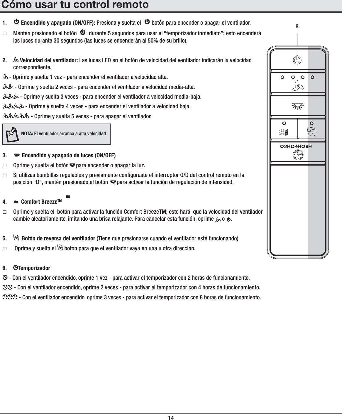
![16Cómo controlar el ventilador con la app WINK (continuación)Cómo usar tu control remoto5=LSVJPKHKKLS]LU[PSHKVY 6--(WHNHLS]LU[PSHKVY ,Z[HISLJLSHJVUÄN\YHJP}UKL=LSVJPKHK)HQHKLS]LU[PSHKVY ,Z[HISLJLSHJVUÄN\YHJP}UKL=LSVJPKHK4LKPHKLS]LU[PSHKVY ,Z[HISLJLSHJVUÄN\YHJP}UKL=LSVJPKHK4LKPHKLS]LU[PSHKVY ,Z[HISLJLSHJVUÄN\YHJP}UKL=LSVJPKHK(S[HKLS]LU[PSHKVY )90:()9,,A, (S[LYUHHSLH[VYPHTLU[LSH]LSVJPKHKKLS]LU[PSHKVYWHYHJYLHY\ULMLJ[VKLIYPZHUH[\YHS3\aKLS]LU[PSHKVY (7(.(+6,5*,5+0+6656-- (WHNHVLUJPLUKLSHZS\JLZKLS]LU[PSHKVY :LSLJJPVUH`KLZSPaHWHYHYLN\SHYVH\TLU[HYSHPU[LUZPKHKKLSHS\a*VUÄN\YHJP}U,Z[HISLJLLSZLU[PKVKLSHYV[HJP}UKLS]LU[PSHKVYZLNUSH[LTWVYHKHO 1 2 3 4 BreezeO OnFAN SPEEDFAN LIGHTFANS3:19 PM>P-P 53%Las conguraciones de velocidad para clima cálido o frío dependen del tamaño de la habitación, la altura del techo, la cantidad de ventiladores y otros factores.ƑClima cálido: (Hacia adelante) Un ujo de aire descendente surte un efecto refrescante.Esto te permite programar el aire acondicionado en una conguración más alta sin afectar tu comodidad.ƑClima frío - (Reversa) Un ujo de aire hacia arriba mueve el aire cálido lejos del cielo raso.Esto te permite jar tu unidad de calefacción en conguración más baja sin afectar tu comodidad.56;(! No esperes a que el ventilador se detenga antes de presionar el botón de reversa. Si el ventilador no está en movimiento, no cambiará de dirección.A. Clima cálidoB. Clima fríoCómo usar tu ventiladorControl remoto - El ventilador está equipado con un control remoto que controla la velocidad y las luces de tu ventilador de techo. Las conguraciones de velocidad para clima cálido o frío dependen del tamaño de la habitación, la altura del techo, la cantidad de ventiladores y otros factores.](https://usermanual.wiki/King-of-Fans/52EWDS/User-Guide-2812245-Page-34.png)