Kongsberg Seatex AS AIS300 Automatic Identification System User Manual
Kongsberg Seatex AS Automatic Identification System
Contents
- 1. user manual
- 2. user manual display
user manual

Preliminary
KongsbergAIS300
AutomaticIdentication
System
Instructionmanual
A300-02/2.0
June2016-preliminary©KongsbergSeatexAS

Preliminary
Documenthistory
Documentnumber:A300-02/Revision2.0
Rev.2.0June2016Preliminarysecondversion—awaitingFCCapproval.
Copyright
©KongsbergSeatexAS
Allrightsreserved.Nopartofthisworkcoveredbythecopyrighthereonmaybereproducedorotherwise
copiedwithoutpriorpermissionfromKongsbergSeatexAS.
Note
TheinformationcontainedinthisdocumentremainsthesolepropertyofKongsbergSeatexAS.Nopartof
thisdocumentmaybecopiedorreproducedinanyformorbyanymeans,andtheinformationcontained
withinitisnottobecommunicatedtoathirdparty,withoutthepriorwrittenconsentofKongsberg
SeatexAS.
KongsbergSeatexASendeavourstoensurethatallinformationinthisdocumentiscorrectandfairly
stated,butdoesnotacceptliabilityforanyerrorsoromissions.
Warning
Theequipmenttowhichthismanualappliesmustonlybeusedforthepurposeforwhichitwas
designed.Improperuseormaintenancemaycausedamagetotheequipmentand/orinjurytopersonnel.
Theusermustbefamiliarwiththecontentsoftheappropriatemanualsbeforeattemptingtooperate
orworkontheequipment.
KongsbergSeatexdisclaimsanyresponsibilityfordamageorinjurycausedbyimproperinstallation,
useormaintenanceoftheequipment.
Comments
Toassistusinmakingimprovementstotheproductandtothismanual,wewelcomecommentsand
constructivecriticism.
e-mail:km.seatex@km.kongsberg.com
KongsbergSeatexAS
www.kongsberg.com

Preliminary
Instructionmanual
Tableofcontents
Glossary..................................................................................................................7
1INTRODUCTION...............................................................9
1.1Aboutthemanual...................................................................................................9
1.2Notationsusedinthismanual.................................................................................9
1.3Productrestrictions.................................................................................................9
1.3.1Restrictionsinguarantee............................................................................9
1.3.2Restrictionsinuse....................................................................................10
1.4Radiofrequencylicense.......................................................................................10
1.5FCCstatements.....................................................................................................10
1.5.1FCCgeneralstatement.............................................................................10
1.5.2FCCpart15statement..............................................................................10
1.6NoteonRFradiationexposurelimitsandAISequipment...................................11
1.7Disposal................................................................................................................11
1.8Equipmenthandling..............................................................................................12
1.9Supportinformation..............................................................................................12
2PRODUCTDESCRIPTION................................................13
2.1Softwareandhardwareversions...........................................................................13
2.2Wheelmarking......................................................................................................13
2.3Purposeandapplications......................................................................................13
2.4Systemcomponents..............................................................................................14
2.5AISUnit................................................................................................................14
2.6GNSSantennadescription....................................................................................15
2.7VHFantennadescription......................................................................................16
2.8AISsystem............................................................................................................16
2.9GNSSsystems......................................................................................................17
2.9.1GPS-GlobalPositioningSystem..............................................................18
2.10IALADGPSdescription.......................................................................................19
2.11VHFinAISsystems.............................................................................................19
3TECHNICALSPECIFICATIONS........................................21
3.1Performancedata..................................................................................................21
3.1.1AIS300system........................................................................................21
3.2Physicaldimensions.............................................................................................21
3.2.1AISUnit..................................................................................................21
3.2.2GNSSantenna.........................................................................................21
3.2.3VHFantenna...........................................................................................22
3.3Power....................................................................................................................22
3.3.1AISUnit..................................................................................................22
3.3.2GNSSantenna.........................................................................................22
A300-02/2.03

Preliminary
KongsbergAIS300
3.4Environmentalspecications................................................................................22
3.4.1AISUnit..................................................................................................22
3.4.2GNSSantenna.........................................................................................23
3.4.3VHFantenna...........................................................................................23
3.5Externalinterfaces................................................................................................23
3.5.1AISUnit..................................................................................................23
3.6Productsafety.......................................................................................................24
3.6.1AISUnit..................................................................................................24
3.7Radiofrequencies.................................................................................................24
3.7.1GNSSantenna.........................................................................................24
3.7.2GNSSreceiver.........................................................................................24
3.7.3VHFantenna...........................................................................................24
3.7.4VHFreceiver...........................................................................................24
3.8Dataoutputs..........................................................................................................24
3.8.1AISUnit..................................................................................................24
3.9Datainputs............................................................................................................25
3.10InterfacesAISUnit...............................................................................................25
3.10.1Serialports..............................................................................................26
3.10.2Ethernetconnection..................................................................................27
3.11LEDindicatorsAISUnit......................................................................................27
3.12Internalalarmsystem...........................................................................................29
3.12.1BIIT........................................................................................................29
3.12.2Alarms....................................................................................................29
3.12.3SNMP.....................................................................................................30
4INSTALLATION..............................................................31
4.1Locationofsystemparts.......................................................................................31
4.1.1AntennalocationforAISsystems.............................................................31
4.1.2GNSSantenna.........................................................................................32
4.1.3VHFantenna...........................................................................................35
4.1.4AISUnit..................................................................................................35
4.2InstallingtheAISUnit.........................................................................................35
4.2.1Installingthepilotplug.............................................................................36
4.3Antennaandcableinstallation..............................................................................36
4.3.1GNSSantennaandcableinstallation.........................................................36
4.3.2VHFantennaandcableinstallation...........................................................37
4.4Electricalinstallation............................................................................................38
5CONFIGURATION...........................................................40
5.1Congurationmethods.........................................................................................40
5.1.1CongurationwithNMEAsentences........................................................40
5.1.2CongurationviaWEBinterface..............................................................41
5.2Messagetypes.......................................................................................................45
4A300-02/2.0

Preliminary
Instructionmanual
5.2.1VDLmessages.........................................................................................45
5.3NMEAsentences..................................................................................................46
5.3.1PIsentences.............................................................................................46
5.3.2Sensorsentences......................................................................................50
5.4Differentialcorrections.........................................................................................51
6GETTINGSTARTED........................................................52
6.1HowtoturnontheAISUnit................................................................................52
6.2AISUnitsettings..................................................................................................52
6.2.1Networksettings......................................................................................52
6.2.2Staticparameters......................................................................................53
6.2.3Radio—VHFchannelsandpower...........................................................54
6.3Statusinformation................................................................................................54
7MAINTENANCE..............................................................56
7.1Periodicmaintenance............................................................................................56
7.1.1Antennacare...........................................................................................56
7.2Softwareupdates..................................................................................................56
7.2.1Softwareupdateroutine............................................................................57
7.3Repairsandmodications....................................................................................57
7.3.1Exchangeofantennacable........................................................................57
7.3.2Exchangeofantenna................................................................................58
7.3.3RepairofAISUnit...................................................................................58
7.3.4InstallationofspareAISUnit....................................................................60
7.4Troubleshooting....................................................................................................61
7.4.1Systemstatus...........................................................................................61
7.4.2Nopower................................................................................................61
7.4.3Externaloutputproblems..........................................................................61
8MECHANICALDRAWINGS..............................................63
8.1AISUnitdimensions............................................................................................64
8.2Bracketwithstrainreliefdimensions...................................................................65
8.3Wallmountingbracketdimensions......................................................................66
8.4DINrailmounting................................................................................................67
9PARTSLIST...................................................................68
9.1Standardcomponents............................................................................................68
9.2Systemaccessories...............................................................................................68
10REFERENCES..................................................................70
AEUDECLARATIONOFCONFORMITY...............................71
BDECLARATIONOFCONFORMITY....................................74
CCOAXCONNECTORINSTALLATION................................75
D½"COAXCABLESPECIFICATIONS................................80
A300-02/2.05

Preliminary
KongsbergAIS300
ERG–214SPECIFICATIONS.............................................81
FANTENNASPECIFICATIONS...........................................83
F.1GNSSantennamechanicaldimensionsandinstallation......................................84
F.2VHFantennamechanicaldrawingandinstallation..............................................86
GLIGHTNINGARRESTORSPECIFICATIONS......................88
HPRODUCTIONTEST........................................................90
6A300-02/2.0

Preliminary
Instructionmanual
Glossary
Abbreviations
AISAutomaticIdenticationSystem
BIITBuilt-inintegritytest
CTSCleartosend
DGPSDifferentialGPS
ECDISElectronicchartdisplayandinformationsystem
ECSElectronicchartsystem
EGNOSEuropeanGeostationaryNavigationOverlaySystem
EMCElectromagneticcompatibility
GPSGlobalpositioningsystem
IALAInternationalAssociationofLighthouseAuthorities
IECInternationalelectrotechnicalcommittee
IMOInternationalMaritimeOrganization
LEDLightemittingdiode
LGNDLogicground
LNALownoisesignalamplier
MIBManagementinformationbase
MKDMinimumkeyboarddisplay
NDSNotdetectedserialport
NMEANationalmarineelectronicsassociation.NMEA0183(reference
IEC61162)isastandardforinterchangeofinformationbetween
navigationequipment.
PGNDPowerground
PIPresentationinterface
PPSPulsepersecond
PRNPseudorandomnoise
PSSPhysicalshorestation
QAQualityassurance
RTSRequesttosend
RTCMRadioTechnicalCommissionofMaritimeServices
SASelectiveavailability
SBASSatelliteBasedAugmentationSystem
SNMPSimplenetworkmanagementprotocol
A300-02/2.07

Preliminary
KongsbergAIS300
SNRSignal/noiseratio
SOTDMASelfOrganisedTDMA
SPSStandardpositioningservice
SWSoftware
TDMATimeDivisionMultipleAccess
UIUserinterface
UTMUniversaltransversemercator
VDLVHFdatalink
VHFVeryhighfrequency
WAASWideareaaugmentationsystem
WEEEWasteElectricalandElectronicEquipment
WGS84WorldGeodeticSystemof1984
8A300-02/2.0

Preliminary
Introduction
1Introduction
1.1Aboutthemanual
Thisinstructionmanualisintendedasareferencemanualforthepersonnelinstalling,
conguringandoperatingthesystemanditcontainsthenecessaryinformationinorder
toinstall,congureandoperatetheAIS300MobileStation.
1.2Notationsusedinthismanual
Thefollowingnotationsareusedinthismanual:
Boldtextisusedforallmenunames.AseriesofmenuselectionsisindicatedbyFile→
New
Italicsisusedformanualnamesandforinformationthatneedsyourattention.
Note
Anoteisusedtodrawattentiontospecialfeaturesorbehaviouroftheequipment.
Caution
Cautionisusedtomaketheuserawareofproceduresandoperational
practicewhich,ifnotfollowed,mayresultindegradedperformanceor
damagetotheequipment.
1.3Productrestrictions
1.3.1Restrictionsinguarantee
ChangesormodicationstotheproductnotexplicitlyapprovedbyKongsbergSeatex
ASwillvoidtheguarantee.
A300-02/2.09

Preliminary
KongsbergAIS300
TheliabilityofKongsbergSeatexASislimitedtorepairofthissystemonlyunderthe
giventermsandconditionsstatedinthesalesdocuments.Consequentialdamagessuch
ascustomer'slossofprotordamagetoothersystemstraceablebacktothissystem's
malfunctions,areexcluded.Thewarrantydoesnotcovermalfunctionsofthesystem
resultingfromthefollowingconditions:
•Incorrectpowerconnection.
•Short-circuitingofGNSSantennacableduringoperationofthesystem(s).
1.3.2Restrictionsinuse
TheAISisacommunicationsystemthatreliesonVHFandGPS.Theantennasshall
beconnectedaccordingtotheinstructions.WithoutproperVHFantennaandantenna
cable,thesensitivityandhencetherange,willbedegraded.TheGNSSreceiverrequires
freesightfromtheantennatothesky,minimumfourvisiblesatellitesandotherwise
normalconditionstooperate.
1.4Radiofrequencylicense
Thisproductcontainsaradio-transmittingdeviceandanationallicensefortheuseof
frequenciesisrequiredforoperation.Useinnationalwaterswillrequireafrequency
licenseissuedbytherelevantnationalauthorities.Theowneranduseroftheequipment
areresponsibleforobtainingsuchalicensepriortoswitchingtheproductON.Itmaybe
requiredtoswitchtheproductOFFwhentheproductisbroughtclosetoshore(closer
than12NM).
1.5FCCstatements
TheFederalCommunicationsCommission(FCC)isanindependentagencyofthe
UnitedStatesgovernmentandregulatesinterstateandinternationalcommunicationsby
radio,television,wire,satelliteandcable.
1.5.1FCCgeneralstatement
ExcerptfromFCCRules,§15.21.
Changesormodicationstotheequipmentnotexpresslyapprovedbytheparty
responsibleforcompliancecouldvoidtheuser’sauthoritytooperatetheequipment.
1.5.2FCCpart15statement
ExcerptfromFCCRules.
ThisdevicecomplieswithPart15oftheFCCRules.Operationissubjecttothe
followingtwoconditions:
10A300-02/2.0

Preliminary
Introduction
1thisdevicemaynotcauseharmfulinterference,and
2thisdevicemustacceptanyinterferencereceived,includinginterferencethatmay
causeundesiredoperations.
ThisequipmenthasbeentestedandfoundtocomplywiththelimitsforaClassAdigital
device,pursuanttoPart15oftheFCCRules.Theselimitsaredesignedtoprovide
reasonableprotectionagainstharmfulinterferencewhentheequipmentisoperatedina
marineand/orcommercialenvironment.Thisequipmentgenerates,usesandcanradiate
radiofrequencyenergyand,ifnotinstalledandusedinaccordancewiththeinstruction
manual,maycauseharmfulinterferencetoradiocommunications.Theequipmentisnot
intendedforoperationinaresidentialarea.Operationinsuchanareaislikelytocause
harmfulinterferenceinwhichcasetheuserwillberequiredtocorrecttheinterference
athisownexpense.
1.6NoteonRFradiationexposurelimits
andAISequipment
Theinternationalregulationsrelatedtoradiationexposurearemainlyaimedatsetting
levelsforportabledevices(andbasestationsitesformobilenetworks).Portabledevices
intendedtobeusedveryclosetothehumanbody(within0.5morless),canhaveRF
powerlevelsintherangeupto10W.
TheKongsbergSeatexASAISequipmentusesVHFtransmission(156to164MHz
band),andisintendedforpermanentinstallationonships(aboveacertainsize).The
antennaismountedhighupinamast.Thisisconsideredacontrolledenvironment.RF
powerfedtotheantennaismaximum12W(thetransmissionisnotcontinuous).Any
humanwillbeinthefareld(>10m)fromtheAISVHFantennaandisnotlikelytobe
exposedtohazardousRFeldsoriginatingfromthisantenna.
1.7Disposal
Allelectricalandelectroniccomponentshavetobedisposed
ofseparatelyfromthemunicipalwastestreamviadesignated
collectionfacilitiesappointedbythegovernmentorlocal
authorities.Thecorrectdisposalandseparatecollection
ofyouroldappliancewillhelppreventpotentialnegative
consequencesfortheenvironmentandhumanhealth.Itis
apreconditionforreuseandrecyclingofusedelectricaland
electronicequipment.Formoredetailedinformationabout
disposalofyouroldappliance,pleasecontactyourlocal
authoritiesorwastedisposalservice.
TheequipmentmaybereturnedtoKongsbergSeatexASif
thereisnolocalWEEEcollection.Theequipmentismarkedwiththispictogram.
A300-02/2.011

Preliminary
KongsbergAIS300
1.8Equipmenthandling
Observethefollowingwhenhandlingtheequipment:
•Allunitsmustbehandledwithcare.
•Thecasecontainingtheunitmustbekeptdryatalltimesandmustbesheltered
fromtheweather.
•Itmustnotbesubjectedtoshocks,excessivevibrationorotherroughhandling.
•Theequipmentmustbepreservedandstoredinsuchawaythatitdoesnotconstitute
anydangertohealth,environmentorpersonalinjury.
•Theunitmust,wheneverpossible,bestoredandtransportedinitsoriginal
transportationbox.
•Thetransportationboxmustnotbeusedforanypurposeforwhichitwasnotintended.
•Thestoragearea'smeantemperaturemustnotbelowerthan–20ºCandnotwarmer
than+70ºC.
•Onceunpacked,theequipmentmustbekeptinadry,non-condensingatmosphere,
freefromcorrosiveagentsandisolatedfromsourcesofvibration.
1.9Supportinformation
•Companyname:KongsbergSeatexAS
•Address:Havnegata9,7010Trondheim,Norway
•Switchboard:+4773545500
•Telefax:+4773515020
•Dutyphone:+4733032407(24hours)
•E-mailaddress:km.support.seatex@km.kongsberg.com
•Website:http://www.km.kongsberg.com/seatex
12A300-02/2.0
Preliminary
Productdescription
2Productdescription
ThischapterdescribestheAISMobileStationsystemandgivesanoverviewofAISand
GPSrelatedinformation.
2.1Softwareandhardwareversions
SystemdeliveredwithSoftwareversion,1.00.xxHardwareversion,1
Revisiontable
DateSoftwareversionHardwareversion
2.2Wheelmarking
Thisproductiswheelmarked.Thewheelmarkwith
serialnumberislocatedonthelabelonthesideand
therearoftheAISUnit.
2.3Purposeandapplications
KongsbergSeatexASprovides,viaitsAIS300mobilestation,atechnicalsolutionthat
enablestheidenticationofothervessels,navigationsaidsttedwithVHFbasedAIS
technologyandvirtualAISAtoN.Itisdesignedtobea“blackbox”forintegration
towardsothernavigationequipmentsuchasECDIS/ECSandradar.AIS300hasan
outstandingreceiversensitivitywhichgivesalargerrangecomparedtounitswiththe
requiredsensitivityof-107dBm.
A300-02/2.013
Preliminary
KongsbergAIS300
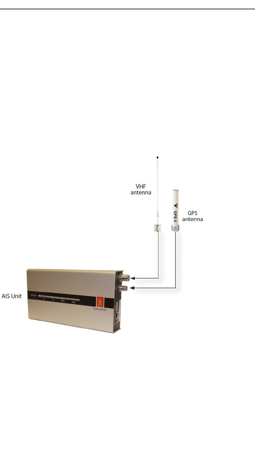
2.4Systemcomponents
Thissystemwillnormallycomprisethefollowingmaincomponents,whichare
physicallyseparated:
•AISUnit
•GNSSantenna
•VHFantenna
Inaddition,thefollowingitemsareneeded:
•AntennacableforGNSSantennaandVHFantenna
•Powercable(twocords)
•Serialconnectiontowardsexternalsensors(ifany)suchasheadingdevice,GNSS
receiveretc.
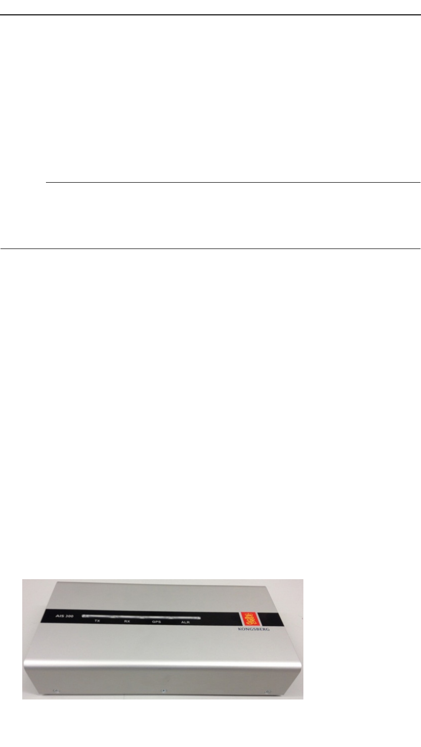
2.5AISUnit
Theunitisastand-alonemountandcomprisesthefollowingmainparts:
•AISmodule
•GPSreceiver
•Powersupply
•Interfacemodule
14A300-02/2.0
Preliminary
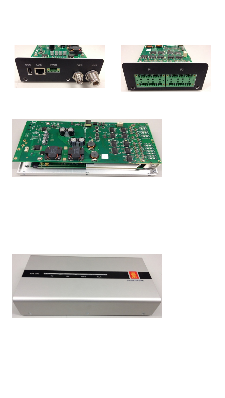
Productdescription
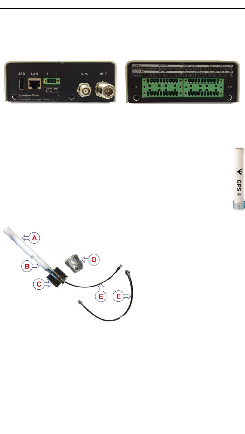
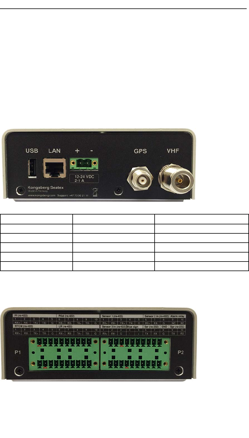
VHF,GPSconnectors,LAN,USBandpowerarelocatedononesideandtheserial
connectionsarelocatedontheotherside.
2.6GNSSantennadescription
TheGPS4antennaisanactivereceivingantennaforthe1575MHzNA VSTAR
GPSsatellitenavigationsystem.
TheGNSSantennahasaright-handcircularpolarisation(RHCP)andabuilt-in
highgain,lownoiseamplier.Ithasafullhemisphericalcoveragedueto
quadrilarhelixantennaelement.
ItisdeliveredwithaninstallationkitwithU-bolts.TheconnectorisFME-female
(pin)(N-femalepigtailwhendeliveredbyKongsbergSeatexAS).
AGNSSantenna
BExtensionpipe
CMountingbracket
DU-bolts
EInterconnectioncables
A300-02/2.015

Preliminary
KongsbergAIS300
2.7VHFantennadescription
A V7isahighqualitydipoleantennadesignedforthemarineVHFradiotelephone
service.Itisahighqualityantennawithadurableconstruction.Ithasavertical
polarizationandomni-directionalradiationpattern.
U-boltsinstainlesssteelareincluded.
2.8AISsystem
InaccordancewithIMOrequirementsallSOLASshipsininternationaltrafcabove
300GTshallcarryanAISmobilestation.Amajortaskforcompetentauthoritiessuch
ascoastalandharbourauthorities,police,customs,military,searchandrescuecentres
andother,istomonitorshiptrafcwithintheirterritorialwaters.ThroughanAIS
infrastructuresystem,thegovernmentalorganisationswillhavethefulltrafcoverview
ofallSOLASships,aswellasAISClassBwithintheAISbasestationcoveragearea.
TheAISsystemprovidesanefcienttooltoincreasethesituationawareness,the
efciencyofoperationsandsafety.Experienceshowsthattheworkloadfortheoperators
involvedinvesseltrackingandmonitoring,isheavilydecreased.
TheimplementationplanforSOLASvesselsstartedin2002andwasnalisedin2004.
AClassAAISmobilestationconsistsofaGPSreceiverandVHFradiomodules.
TheAISmobilestationusesGPSsatellitestodeterminevesselposition.Theposition
datashould,however,comefromtheship’sprimarynavigationsystem.Ifthisisnot
available,thepositionwillbeprovidedfromtheinternalGPSreceiver.TheinternalGPS
receiverisalsousedfortime-synchronisationofreceivedandtransmitteddata.
VHFcommunicationisusedforbroadcastandreceptionofvesselpositiondata,
navigationaldata,staticandvoyagerelatedinformationwithothervesselsandbase
stations.
ForanAISClassAmobilestationseriallinecommunicationandtheNMEAdata
protocolareusedtoexchangeAISdatawithothernavigationsystems.AISdataare
displayedontheMKDunitorexternalsystemssuchasECDIS/ECSorradar.
16A300-02/2.0
Preliminary
Productdescription
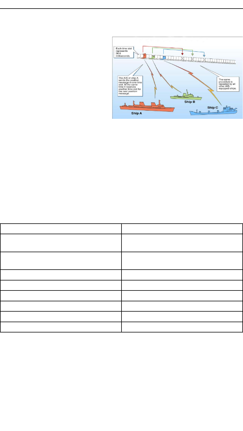
TheSelf-OrganisedTime
DivisionMultipleAccessprotocol
(SOTDMA)organisesaccessforall
usersbyoperatingwithtime-frames
dividedintosingleslots.AISis
basedonSOTDMAcommunication
ontwofrequencies(161.975MHz
and162.025MHz).Vesselswill
rstlisteninordertoestablishthe
slottableandthenstartsending
inavacantslot.Wheninnormal
operation,eachstationsendsin
apreviouslyannouncedorrandomlychosenslot.Futuretransmissionslotswillbe
allocatedandcommunicatedtosurroundingAISmobilestations.Henceaself-organised
communicationavoidstransmissioninsameslots.
Thesystemisdesignedtogivepreferencetoclosetargets.Targetsfarawaywilldrop
outrstintheeventofoverload.
ThelengthofatimeslotwithintheSOTDMAtelegramis26.6milliseconds.There
aremaximum2250slotsperminuteoneachAISfrequency,intotal4500slots.One
navigationmessagefromashipoccupiesoneslot.
Thetransmissionrateofapositionmessage(msg1-3)dependsonthespeedandturn-rate
ofavessel.Staticinformation(msg5)issentevery6minutes.
Ship’sdynamicconditionsReportinginterval
Shipatanchorormooredandnotmoving
fasterthan3knots
3minutes
Shipatanchorormooredandmoving
fasterthan3knots
10seconds
Ship0to14knots10seconds
Ship0to14knotsandchangingcourse3.3seconds
Ship14to23knots6seconds
Ship14to23knotsandchangingcourse2seconds
Ship>23knots2seconds
Ship>23knotsandchangingcourse2seconds
2.9GNSSsystems
GNSS(GlobalNavigationSatelliteSystem)isagenerictermforsatellitenavigation
systemsprovidingautonomousgeo-spatialpositioningwithglobalcoverage.GPSisthe
onlyGNSSwithfullconstellation.However,GLONASSisoperablebutdonothavefull
constellation.GalileoisathirdGNSS,whichisinthedevelopmentphase.
A300-02/2.017

Preliminary
KongsbergAIS300
2.9.1GPS-GlobalPositioningSystem
TheGlobalPositioningSystem(GPS)isasatellite-basednavigationsystemmadeupof
anetworkofsatellitesplacedintoorbitbytheU.S.DepartmentofDefence.GPSwas
originallyintendedformilitaryapplicationsbutinthe1980esthegovernmentmadethe
systemavailableforcivilianuse.
GPSprovidesahighlyaccurateandcontinuousnavigationservice.Itprovides24-hour,
allweatherandglobalcoverage.
Thesystemisdividedintothefollowingthreesegments:
SpacesegmentThissegmentconsistsofatleast24satellites(21activeplus
3operatingspares)in12-hourcircularorbits.Atanaltitude
of20200km,eachsatelliteistransmittingorbitalandclock
parameters.
ControlsegmentThissegmentcomprisesGroundControlStations
geographicallyspreadformonitoring,up-loadingandcontrol
ofthesatellitetransmittedcharacteristics.
UsersegmentThissegmentcomprisesGPSreceiversinstalledonboard
ships,aircraftetc.totracksatellitesignalsandtransformthem
intoposition,velocityandtime.
EachGPSsatellitetransmitsradiosignalsattwomicrowavefrequenciesintheLband,
1575.43MHz(L1)and1227.6MHz(L2).
TheL1signalismodulatedbyaprecise(P)codeforPrecisePositioningService(PPS)
andacourse/acquisition(C/A)codeforStandardPositioningService(SPS).TheP
codeisformilitaryandauthorisedpersonnelonlyandisencryptedbeforebroadcastto
GPSusers.TheC/Acodeisforcivilusers.Until1May2000theaccuracyoftheC/A
codewasdegradedto100m(2DRMS)horizontalpositioningbytheuseofSelective
Availability(SA).However,SAisnowswitchedoffandthepositionaccuracyofthe
systemisabout16metres95%CEP .
ThefundamentaltechniqueforGPSisone-wayrangingfromthesatellites.Triangulation,
basedonrangingfromthesatellites,isthebasisofthesystem.Inordertotriangulate,
theGPSmeasuresdistanceusingthetraveltimeofaradiomessage.Tomeasuretravel
time,timingiscrucial.GPSthereforeneedsveryaccurateclocks.Thetransmissionis
referredtohighlyaccurateatomicfrequencystandardsonboardthesatellites,whichare
insynchronisationwiththeGPSsystemtimebase.
Thetimedifferencefromwhenthesignalleavesthesatellitesuntilitisreceivedatthe
GPSreceiver,ismeasured.Thedistanceiscomputedbymultiplyingwiththespeedof
light.Oncethedistancetoasatelliteisknown,thesatellite'spositioninspacemustbe
found.TheGPSsatellitesarelaunchedintoverypreciseorbitsandtheirpositionis
transmittedtotheuser.Knowingthesatellites'positionandthedistancetotheuser
receiver,theuserpositioncanbecomputed.Threeperfectmeasurementscansolvea
three-dimensionalpointinspace.
18A300-02/2.0

Preliminary
Productdescription
However,thecrystalclocksintheGPSreceiversaredrifting,andthepositionistherefore
inaccurate.Tocalculateathreedimensionalposition,fourunknownshavetobesolved
(latitude,longitude,heightandreceiverclockoffset).Tosolvethisequationwithfour
unknownsitisnecessarywithrangemeasurementsfromfourormoresatellites.
Thegeometry,andhencetheaccuracyofthepositioncalculation,varieswiththenumber
ofsatellitesavailableandtheirlocation.
UsingdifferentialcorrectionsfromoneormoreGPSReferenceStationssignicantly
reducesallmajorerrorsources.ThisprincipleiscalleddifferentialGPS(DGPS).
2.10IALADGPSdescription
AnIALADGNSSreferencestationgeneratesdifferentialGNSScorrections.Raw
pseudo-rangeobservationsandotherpertinentdatafromtheinbuiltGNSSreceiverare
usedtocalculatecorrections.ThegeneratedRTCMmessagesaresentviatheMSK
modulatortoaDGNSSReferenceStationTransmitterwhichampliesthesignaland
broadcaststhecorrectionsintheMFfrequencyrangetomariners.Onboardthevessel
thesecorrectionsareusedintheDGPSreceiverwheretheGPSpositioniscorrected
accordingly.
2.11VHFinAISsystems
TransmissionintheAISsystemisbasedonVHF(V eryHighFrequency).AISmobile
stations(onboardvessels),AISAtoNs,AISBaseStationsandotherAISdevicesare
transmittingontwostandardisedAISchannels;ChannelA(161.975MHz)andChannel
B(162.025MHz).Twopowerlevelsareusedonthevessels;low(1W)andhigh
(12.5W).
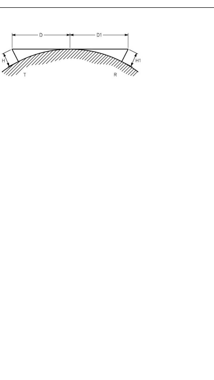
Therange,distancebetweentransmittingunitandreceivingunit,ismainlydepending
onantennaheightandtheantennainstallation.Useofforexamplecombinerswill
introducealossandhencereducetherange.Itisimportanttoinstalltheantennaas
highaspossible.Theoreticalrangecanbeestimatedbasedonthefollowingformula,
whichisalineofsightestimation:
D(km)=p
12,75xH(m)
D=Distance(range)inkilometers.H=antennaheightinmetres.
Notethatboththetransmitterandreceiverside(seegure)needtobeconsidered.This
isanestimationoflineofsight,andisveryconservativeforVHFrangecalculations.
InordertogiveabetterestimateofVHFrangeundernormalmetrologicalconditions
10%shouldbeaddedtothelineofsightdistance.Specialmetrologicalconditions
mayaffecttheradiorangeconsiderably.
A300-02/2.019
Preliminary
KongsbergAIS300
20A300-02/2.0

Preliminary
Technicalspecications
3Technicalspecications
3.1Performancedata
3.1.1AIS300system
AISmodule
SensitivityBetterthan-107dBm
3.2Physicaldimensions
3.2.1AISUnit
Height54.73mm(includingmountingbracket)
Width132.55mm
Length260mm(includingconnector)
Weight1.3kg(withoutmountingbrackets)
MountingbracketsStandard:122.5mmx389.5mm(withstrainrelief)
Optional:122.5mmx272mm(wallmount)
Optional:DINrailbracket
3.2.2GNSSantenna
TypeProcomGPS4
Height230mm
Diameter33mm
Weight0.15kg
ColourWhite
ConnectortypeFMEmalewithpigtailtoN-female
A300-02/2.021

Preliminary
KongsbergAIS300
TheGNSSantennahasaright-handcircularpolarisation(RHCP)andabuilt-inhigh
gain,lownoiseamplier.Ithasafullhemisphericalcoverageduetoquadrilarhelix
antennaelement.ItisdeliveredwithaninstallationkitwithU-bolts.
3.2.3VHFantenna
TypeComrodA V7
Height1250mm
Diameter25mm
Weight1kg
ConnectortypeN-female
A V7isahighqualitydipoleantennadesignedforthemarineVHFradiotelephone
service.Itisahighqualityantennawithadurableconstruction.Ithasavertical
polarizationandomni-directionalradiationpattern.U-boltsinstainlesssteelareincluded.
3.3Power
3.3.1AISUnit
Inputvoltage+24VDCnominal(operationalrange12to32VDC)
PowerconsumptionMax.30W
3.3.2GNSSantenna
TypeProcomGPS4
V oltage5VDCfrommainunit
3.4Environmentalspecications
3.4.1AISUnit
EnclosurematerialAluminium
Operatingtemperaturerange-15°Cto+55°C
Recommendedoperating
temperature
Roomtemperature(+20°C)
Storagetemperaturerange-20°Cto+70°C
OperatinghumidityMax.95%non-condensing
22A300-02/2.0

Preliminary
Technicalspecications
StoragehumidityLessthan55%
IngressprotectionfrontIP42
IngressprotectionrearIP21
Electromagneticcompatibility
(immunity/emission)
IEC60945/EN60945
VibrationIEC60945/EN60945
3.4.2GNSSantenna
TypeProcomGPS4
Operatingtemperaturerange-50°Cto+70°C
RelativehumidityHermeticallysealed(100%)
EnclosurematerialWeather-resistantlow-lossplastic
3.4.3VHFantenna
TypeComrodA V7
EnclosurematerialFibreglass
Operatingtemperaturerange-55°Cto+71°C
Windrating55m/s
3.5Externalinterfaces
3.5.1AISUnit
Serialports5RS-422(I/O),2RS-422(I),2RS-232(service,
spare)
BaudrateUpto115200bytes/sec
LAN1Ethernetport
USB1infront
ALROpen/closed(normallyclosed)
BluesignSwitch
A300-02/2.023

Preliminary
KongsbergAIS300
3.6Productsafety
3.6.1AISUnit
Electricalsafety(LVD)[1]IEC60950-1/EN60950-1
3.7Radiofrequencies
3.7.1GNSSantenna
TypeProcomGPS4
L11575MHz
Gain(inaxialdirection)32dBi
3.7.2GNSSreceiver
Typeu-Blox
GPSL11575.42MHz
3.7.3VHFantenna
TypeComrodA V7
FrequencyVSWR<1.5:1,156to162MHz
VSWR<2:1,145to165MHz
Gain2dBi
3.7.4VHFreceiver
TypeKongsbergSeatexAISmodule
Frequency156to162.0375MHz
3.8Dataoutputs
3.8.1AISUnit
MessageformatNMEA0183v.3.0,andsomeproprietarymessages
1.Thisequipmentisintendedforprofessionaluseonly.
24A300-02/2.0
Preliminary
Technicalspecications
3.9Datainputs
NMEAsentencesPI,Pilot,RTCM,LR,Sensor1,Sensor2,Sensor3
accordingtoIEC61993–2.
3.10InterfacesAISUnit
Theantennaconnections,power,EthernetandUSBinterfaceislocatedononesideof
theAISmobilestation.
ConnectorTypeConnectedto
VHFN-connectorfemaleVHFantenna
GPSTNCconnector50OhmfemaleGPSantenna
PWR2–pinPhoenixscrewterminalsPowerinput,1=-(N),2=+(P)
LANRJ-4510/100Mbit/sautosenseSwitch/router/equipment
USBUSBUSBstickforSWupdate
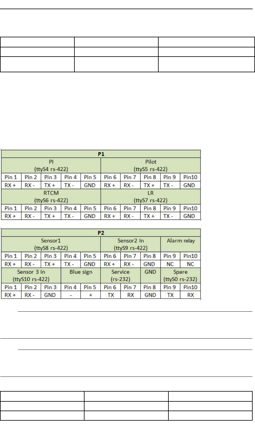
Theserial,alarmrelayandBluesigninterfacesarelocatedontheoppositeside.P1and
P2constituteve5–pinRS–422I/Oports,two3–pinRS–422Iports,two3–pinRS–232
ports,one2–pinAlarmRelayandone2–pinBluesignport.
A300-02/2.025
Preliminary
KongsbergAIS300
ConnectorTypeConnectedto
P12*10pinPhoenixscrewterminalsPI,Pilot,RTCM,LR
P22*10pinPhoenixscrewterminalsSensor1,Sensor2,Alarm,Sensor3,Blue
sign,Service,Spare
3.10.1Serialports
TheAISmobilestationhassevenRS–422andtwoRS–232ports.Inadditionanalarm
relayandabluesignportforinlandwaterwayuse.
ThebelowtableshowsthepinningforthedifferentconnectionsavailableonP1andP2
seenfromthefront.EachofP1andP2consistsoftwo10–pinconnectorsnumbered
fromlefttoright.ThecongurationcanbecompletedintheWEBinterface.
Note
ThetwoRS–232portshaveacommongroundthroughpin8onthelowerconnector
onP2.
Note
ForRS–422ports,RX/TX-correspondtosignallineRX/TXAandRX/TX+correspond
toRX/TXB.
Baudratesareasfollows:
SerialportDefaultbaudrateRange
PI384004800to115200
Pilot384004800to115200
26A300-02/2.0
Preliminary
Technicalspecications
SerialportDefaultbaudrateRange
RTCM96004800to115200
LR384004800to115200
Sensor148004800to115200
Sensor248004800to115200
Sensor348004800to115200
Service115200NA
Spare
3.10.1.1Termination
Theserialinterfacesuse1kOhmtermination.TheAISUnitserialdatareceiverdraws
lessthan2mAat2V .
3.10.1.2Outputdrivecapability
Output(talker)
Upto10listeners(RX)maybeconnectedtoeachAISUnittalkerline(TX-RS422
dataport).
Input(listener)
TheAISUnitlistenercircuitwillnotdrawmorethan2mAfromthelineata2V
voltagelevel.
Caution
Donotconnecttwotalkerlinestogether.
3.10.2Ethernetconnection
LANAIS
ThisistheLANportwhereAISPIdataarereceivedfromtheAISUnitandtheportto
usewhenconguringthesystemviaWEBinterface.Capacityis100Mbps.
3.11LEDindicatorsAISUnit
AtthetopoftheunittherearefourLEDindicatorswhichindicatevarioussituations
dependingonthestateoftheunit.Seenfromrighttoleft:ALR,GPS,RXandTX.
DuringstartuptheLEDshavethesefunctions:
•TheLEDtotheleft(TX)turnsredafter
power-on.
A300-02/2.027
Preliminary
KongsbergAIS300
•Theledtotheright(ALR)isrstunlitand
thenstartstoashyellowwhentheAISUnit
softwareisrunning.
•TheLEDtotheright(ALR)continuestoash
yellowuntiltheAISUnitisreadytosend.
DuringnormaloperationtheLEDshavethesefunctions.
•TheTXLEDhasthesefunctions:
–TXtransmittingonChannelA,theLED
totheleftashesgreen.
–TXtransmittingonChannelB,theLED
totheleftashesyellow.
–TXtransmittingonChannelC,theLED
totheleftashesred.
–TXisoff,theLEDtotheleftisconstantly
red.
•TheRXLEDhasthesefunctions:
–RXreceivingonChannelA,thesecond
LEDtotheleftashesgreen.
–RXreceivingonChannelB,thesecond
LEDtotheleftashesyellow.
–RXreceivingonChannelC,thesecond
LEDtotheleftashesred.
•TheGPSLEDhasthesefunctions:
–WhentheAISUnitistrackingsatellites,
thesecondLEDtotherightashesgreen.
–WhentheAISUnitreceivesGPSdata
butnopositionortime,thesecondLEDto
therightashesyellow.
•TheAlarmLEDhasthisfunction:
–Whenthereisanalarmsituation,theLED
totherightisconstantlyred.Otherwise
itisnotlit.
28A300-02/2.0

Preliminary
Technicalspecications
3.12Internalalarmsystem
3.12.1BIIT
TheAISmodulehasabuilt-inalarmfunctionality.ThealarmisgeneratedbytheBuilt
InIntegrityTest(BIIT).
Thesoftwarehandlesgeneratedalarms.Thealarmmayleadtosomekindofactions
takenbythesystem.Thisdependsonwhatkindofalarmthatarises.Thealarm
generatedbytheBIITmayleadtostopintransmissionofmessages.Whenanalarm
arises,thiswillbeidentiedbyaredalarmLED.Therewillalsobegeneratedanalarm
messageonthePIport.
3.12.2Alarms
ThefollowingalarmscanbesentfromtheAISUnitonPI.Responsetoanalarmis
listedintherightcolumn.
AlarmExplanationResponse
TxmalfunctionIftheAIS300detectsthatitisunable
tomaintainradiofrequenciesduring
transmissionorthatitfailstoshut
downTXafterrampdown.
Shutdownof
transmitter
AntennaVSWR
exceedslimit
Antenna/cableerrorordisconnected.
Typicallywaterpenetrationinantenna
orcable.
Continueoperation
RXmalfunction(Ch
A/B/70)
InternalerrorinAIS;Lost
communicationwithFPGA.
Continueoperation
GeneralfailureOneormoreoftheinternalSDR
processeshavestoppedresponding.
Shutdownof
transmitter
UTCclocklostNointernalGPS,duetoantenna/cable
error/disconnectedorGPSreceiver
error.
Continueoperation
MKDconnectionlostNoMKDconnected.Continueoperation
Internal/External
GNSSposition
mismatch
Largepositionmismatch(100m),
takenGPSantennapositionsinto
account,betweeninternalandexternal
GPSreceiverwhichispresentformore
than15minutes.
Continueoperation
NavStatusincorrectMismatchbetweenspeedandentered
navstatus.
Continueoperation
HeadingsensoroffsetSustaineddifferencebetweenCOGand
headingof45degreesormoreforat
least5minutes.
Continueoperation
A300-02/2.029

Preliminary
KongsbergAIS300
AlarmExplanationResponse
ActiveSARTActiveSARTmessagehasbeen
received.
Continueoperation
ExternalEPFSlostNoinputfromexternalpositionsource.Continueoperation
Nosensorpositionin
use
Novalidexternalnorvalidinternal
positionprovided.
Continueoperation
NovalidSOG
information
Novalidinputof,orinternalSOG.Continueoperation
NovalidCOG
information
Novalidinputof,orinternalCOG.Continueoperation
Headinglost/invalidNoinputofheading.Continueoperation
NovalidROT
information
NoinputofRateOfTurn
indicator/sensor.
Continueoperation
3.12.3SNMP
SimpleNetworkManagementProtocol(SNMP)isan"Internet-standardprotocolfor
managingdevicesonIPnetworks".ASNMPagentisinstalledontheAISmoduleinthe
AISUnittrappingtheBIITalarmsofthesystem.TheManagementInformationBase
(MIB)canbedownloadedfromFTPserveronrequest.
30A300-02/2.0

Preliminary
Installation
4Installation
ThischaptercoversinstallationoftheAISUnit,theGNSSantennaandtheVHFantenna.
Theinstallationincludes:
•Locationofthesystemparts(theAISUnit,GNSSantenna,VHFantenna)
•InstallationoftheAISUnit
•Installationofcoaxconnectors
•InstallationoftheGNSSantennaandcable
•InstallationoftheVHFantennaandcable
•Connectionofcablesbetweenthesystemandexternalequipment
•Systemconguration
4.1Locationofsystemparts
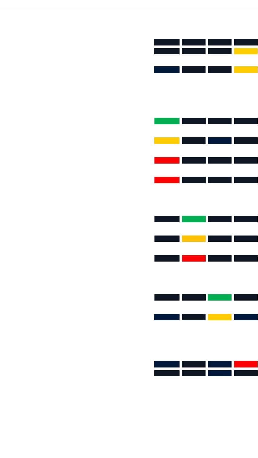
4.1.1AntennalocationforAISsystems
Thissystemislikelytobeco-locatedwithothertypesofradioequipmentatthe
installationsite.Thereforespecialprecautionsarerequiredwhenmountingtheantennas
forGNSSandVHF.Thegurebelowgivessomeguidelinesforantennalocations.
A300-02/2.031
Preliminary
KongsbergAIS300
4.1.2GNSSantenna
ThemostcriticalaspectofthesysteminstallationisthelocationoftheGNSSantenna.
Incorrectorinadequateinstallationcanleadtopoorpositioningperformanceorcomplete
lossofposition.
Iftheantennaisinstalledinapoorlocation,itcansufferfrommasking,multipathor
interferencefromotherradiosourceswhichcanaffectthepositionperformance.
Masking
TheGNSSantennashouldhaveanunobstructedlineofsighttothesky.Thesignalsfrom
thesatellitepropagatebyline-of-sight,whichmeansthatiftheantennacannotseethe
satellite,thereceptionwillbeseverelyimpaired,ifitoccursatall.
Potentialobstructionsareothermastsandantennas,cranes,rigsandxedplatforms,
buildingsinports,highcliffsorhillsclosetoshore.Theimpactofthiscanbeanything
fromdegradedperformancetoacompletelossofpositioning.
32A300-02/2.0
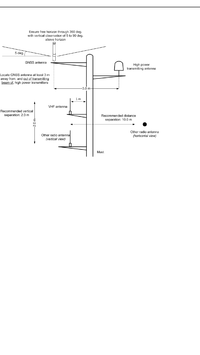
Preliminary
Installation
Figure1Goodantennalocation
Figure2Badantennalocation,typicallymaskingsituation
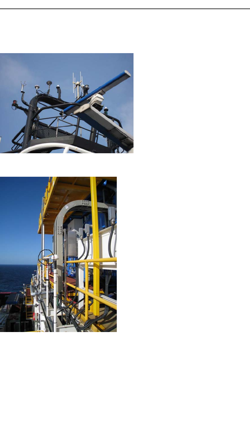
Multipath
Inappropriatelocationoftheantennacanresultintheantennareceivingreectionsof
theincomingsignalaswellasthesignalitself(multipath).Thereectedmultipath
signaltakesalongerpaththanthedirectsignal,introducinganerrorintotheposition
calculation.
A300-02/2.033
Preliminary
KongsbergAIS300
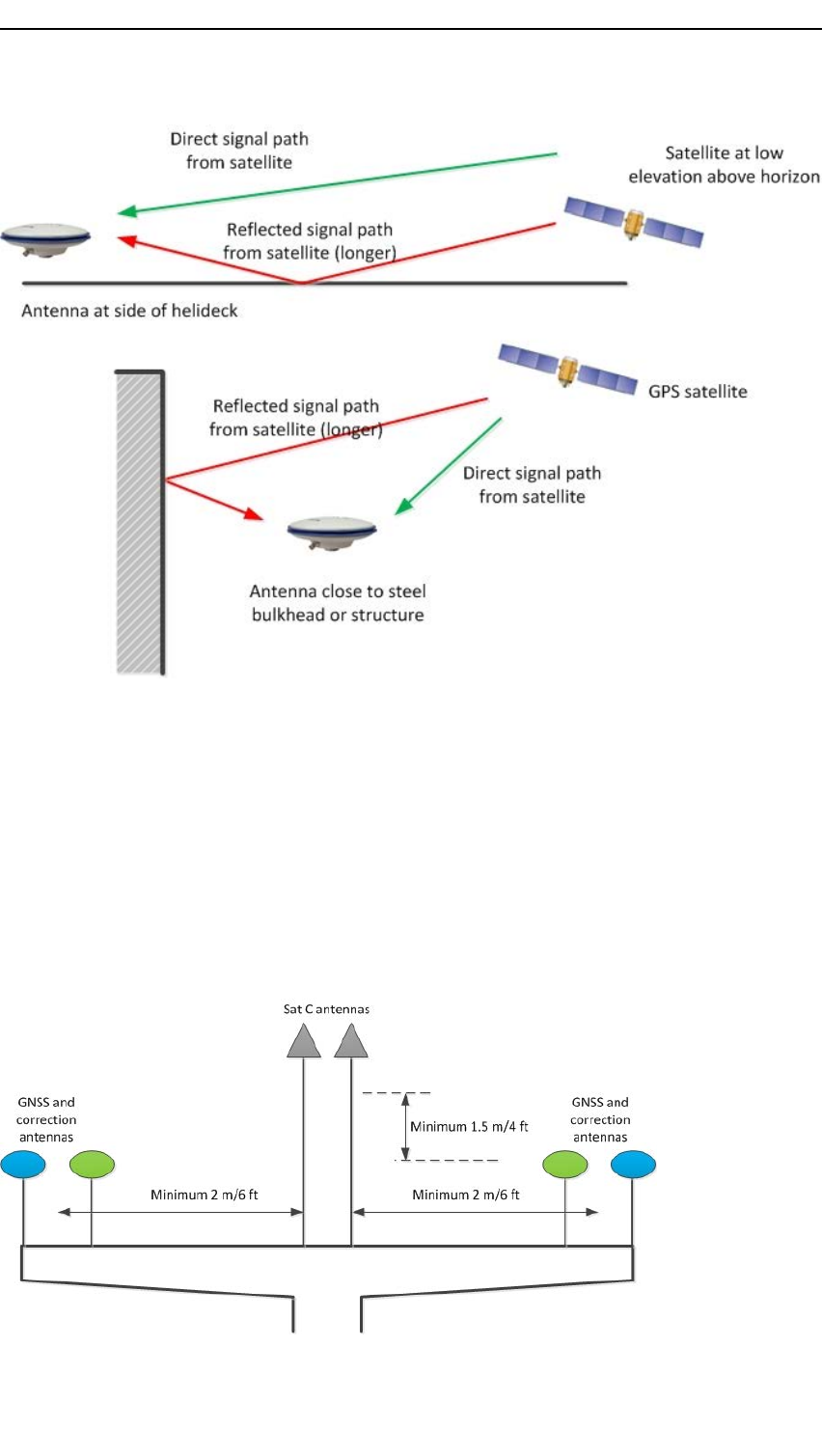
Interferencefromotherradiatingsources
Interferencecanbecausedbycloseproximitytootherradiatingsources.Installing
GNSSantennasincloseproximitytosatellitecommunicationsystemsoperatinginor
nearbyGPS/GLONASSfrequencybands(1.2to1.6GHz)shouldbeavoided(i.e.SatC,
Iridium).Ideallytheantennashouldbesituatedataminimumof3metresfromother
radiatingsources.Asthisisnotalwayspracticallypossible,acompromiselocation
mustbesought.
RecommendeddistancetoSatCisminimum2metreshorizontallyandminimum1.5
metresvertically.
34A300-02/2.0

Preliminary
Installation
Duringinstallation,comprehensivetestsshouldbecarriedoutforpotentialinterference
byconductingtransmissionsfromeachRFsourceforextendedperiods,individually
andsimultaneously.
4.1.3VHFantenna
FortheVHFantenna,considerthefollowing:
•Mounttheantennainalocationwherefreesightisensured.Freemounting,andas
highaspossibleispreferable,otherwisetheSWRandtheradiationdiagramwillbe
inuenced.Thehigherthelocation,thebetterthecoverage.
•Avoidmountingtheantennaparallelwith,andinthevicinityof,othermetalparts
suchasmasts,supportingwiresetc.
•Theantennashouldbeprotectedfromdirectilluminationofradarbeamsandother
transmittingantennassuchasInmarsatantennas.
•Runthecablesinasteelpipeinareaswherethedangerforradiationishigh.
4.1.4AISUnit
Wheninstallingtheunit,notethefollowing:
•Theunitisdesignedforindoorinstallation.Avoidlocationswithheavyvibrations,
strongelectronicelds(closetotransformers),excessiveheat.
•Theunitshouldberesilientlymountedtobeinaccordancewiththeenvironmental
standardIEC60945/EN60945.
•Itisrecommendedthattheareaaroundtheunitiskeptfreefromdustandstatic
electricity.
•Allconnectionstotheunitareontheshortsidesoftheunitandavailablespacefor
cableconnectionsandservicemustbeprovided.
4.2InstallingtheAISUnit
TheAISUnitisdefaultdeliveredwithabracketdesignedwithsolutionforstrainrelief.
HowtoinstalltheAISUnitwithstrainrelieforwallmountbracket
1Placethebracketwheretheunitshallbemountedandmarktheholesforthescrews.
2Drilltheholes.
3MounttheAISUnitonthebracket.
4MountthebracketwiththeAISUnitwheretheholesweredrilled.
5Whencablesareconnected,fastenthecableswithstripstothestrainrelief.
HowtoinstalltheAISUnitwithDINrailbracket(optionalequipment)
1FastenthebrackettotheAISUnitwithfourscrewsattherearoftheunit.
2FastentheAISUnitwiththebrackettotheDINrail.
A300-02/2.035
Preliminary
KongsbergAIS300
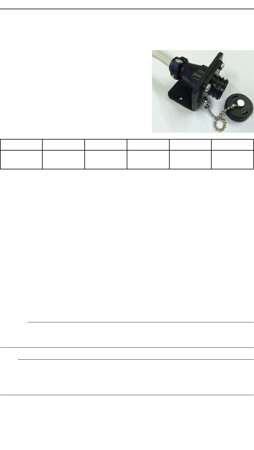
4.2.1Installingthepilotplug
TheAISUnitisdefaultdeliveredwithapilot
plug,partA300–08,withoutserialcable.Aplug
withcable,partA300–07,canbedeliveredas
anoption.
Useapairedcablewithcordsofminimum0.5
mm2toassemblethepilotplug.
Usethepinninginthetabletoconnectthepilot
plugtotheAISUnit.
Pilotplug14569
AISUnit
portRX+RX-TX+TX-GND
Relatedtopics
•Serialportsonpage26
4.3Antennaandcableinstallation
Themaximumlengthforeachoftheantennacoaxialcablesis30metresforRG214and
100metresfor1/2"Superex.Iflongercablesareneeded,alownoisesignalamplier
(LNA)shouldbetted.
Itisrecommendedtouselightningarrestors.SeeLightningarrestorspecicationson
page88.
4.3.1GNSSantennaandcableinstallation
ThecablerecommendedfortheGNSSantennais½"superex.
Caution
TheGNSSconnectoristheconnectorlocatedtotheleft(TNC).Donot
confusewiththeVHFconnector(N).
Note
ThecablerunningfromtheGNSSantennatothemainunitshouldbeasstraightas
possible.Donotcrushorcrimpthecablewithtie-downs,asthiswillaffecttheelectrical
propertiesofthecable.
Procedure
1Attachtheinterconnectionpigtailcabletotheantennaconnector.
36A300-02/2.0

Preliminary
Installation
2Wrapthecableconnectionwithwaterproofself-vulcanisingtape.
3Threadtheinterconnectioncablethroughtheextensionpipeandthemounting
bracketandattachtheextensionpipewiththemountingbrackettotheantenna.
4Attachtheantennamountingbrackettotheship'smastheadorpolewiththeU-bolts.
5Connecttheinterconnectioncabletothe½"superexcable.
6Wrapoutdoorcableconnectionswithwaterproofself-vulcanisingtape.Analternate
wayofwaterproongistouseheatshrinkhosewithglue.Thehoseshouldcover
thewholeconnectorandpartofthecable.
7Dependentonthecableinstallation,securethecabletothemasteveryonetothree
metreswithclampsorbands(non-metal).
8Checktheantennacableforshort-circuiting.
9Connecttheotherendofthe½"superexcabletotheinterconnectioncable.This
cableisdeliveredinordertogetsecurecablerunstothemainunit.
10Connecttheinterconnectioncabletothereceivingdevice.AllGNSSreceivers
providenecessarypowerthroughtheirantennaRFconnectors.
Relatedtopics
•GNSSantennamechanicaldimensionsandinstallationonpage84
4.3.2VHFantennaandcableinstallation
Theconstructionofthemountenablesroutingofthecableeitheralongtheinsideorthe
outsideofthemasttube.AnRG-214cableisusedfordistancesshorterthan30metres,
whilea½"superexcableisusedfordistancesupto100metres.
Caution
IftheantennacableisattachedtotheAISUnit,donotattachtheantenna
cabletotheantennawhentheunitisrunning.Iftheantennacableis
short-circuitedwithPOWERON,theAISmodulecanbedamaged.
Caution
DonotconnecttheVHFantennacabletotheGNSSconnectorasthiscan
damagetheGNSSreceiver.
HowtoinstalltheVHFantenna
1AttachtheantennatoamasttubeorpolebyusingtheprovidedU-bolts.
2Attachtheantennacabletotheantenna.
3Wrapoutdoorcableconnectionswithwaterproofself-vulcanisingtape.Analternate
wayofwaterproongistouseheatshrinkhosewithglue.Thehoseshouldcover
thewholeconnectorandpartofthecable.
4Makesurethegroundstrapattheantennabaseisconnectedtoasuitableplace
ensuringgoodgrounding.
A300-02/2.037

Preliminary
KongsbergAIS300
5Sealtheterminalsofthegroundstrapfrommoisturetopreventcorrosion.Paintor
siliconesealantisrecommendedforthis.
6Securethecabletothemasteveryonetothreemetreswithclampsorbands.
7RoutetheconnectorattheotherendoftheantennacabletotheAISUnitand
connectthecabletotheN-connectornamedVHF.AshortRG-58orRG-214cable
isoftenneededinordertosecurecablerunstotheunit.
Relatedtopics
•VHFantennamechanicaldrawingandinstallationonpage86
4.4Electricalinstallation
Theelectricalinstallationconsistsof:
•ConnectingacablebetweentheGNSSantennaandtheAISUnit.
•ConnectingacablebetweentheVHFantennaandtheAISUnit.
•Connectingcableswithoutput/inputdatabetweentheAISUnit,networkandother
equipment.
•Supplying12to32VDCpowertotheAISUnit.
Caution
BeforepoweringontheAISUnit,makesuretheantennacablesand
antennasareconnected.Connectingordisconnectinganantennaorantenna
cablewhentheAISUnitisalreadypowered,maypermanentlydamagethe
antennaportontheAISUnitortheantennaitself,voidingyourwarranty.If
theantennacableisshort-circuitedwithpoweron,thereceiverwithinthe
AISUnitcanbedamaged.
Howtocarryouttheelectricalinstallation
Note
Theantennacablesmustbeasstraightaspossible.Donotcrushorcrimpthecablewith
tie-downsasthiswillaffecttheelectricalpropertiesofthecables.
1ConnecttheGNSSantennacabletotheconnectormarkedGPSontheAISUnit.
2ConnecttheVHFcabletotheconnectormarkedVHFontheAISUnit.
3ConnectthenetworkcableforLAN.
4ConnectthepowersupplytothepowerconnectorontheAISUnit.Minus(-)and
plus(+)asindicatedontheunit.
5Whenallcablesareconnected,powerontheAISUnit.
6Whenthepowerisconnected,allLEDsareunlitforabout30seconds.Thenall
LEDswillstarttoblinkinnormaloperation
38A300-02/2.0

Preliminary
KongsbergAIS300
5Conguration
5.1Congurationmethods
ThissystemisprimarilymadeforcongurationwithstandardisedAISNMEAsentences.
ViaPI(serialorLAN).ThesesentencesaredescribedintheAISmobilestationtest
standardIEC61993–2.Thedescribedcongurationsentencesarenormallysenttoa
mobilestationfromauserinterface(UI)suchasECDISorRADAR.
InordertomaketheuserindependentofacongurationUIandNMEAsentences,a
WEBinterfacehasbeenincludedinthissystem.
IPaddresswhendeliveredfromfactoryis:
•LAN10.0.21.60
•Subnet255.255.255.0
•Gateway10.0.21.1
5.1.1CongurationwithNMEAsentences
TheAISmobilestationteststandardIEC61993–2denestheAISNMEAsentences.
Newsoftwareupgradeswillbeavailableafterchangesinthestandard.AstheNMEA
(PI)sentencesarestandardisedandavailableinthestandard,thismanualwillnot
describetheNMEAsentences.
TCP/IPport(multiclient)forcongurationofthesystemis4712.
Relatedtopics
•PIsentencesonpage46
40A300-02/2.0
Preliminary
Conguration
5.1.2CongurationviaWEBinterface
TheusercanaccesstheWEBinterfaceiftheIPaddressisknownandtheaddressis
availablefortheuser.TheWEBinterfaceusesthesetuplesinthesystemandchanges
arewrittentotheseles.
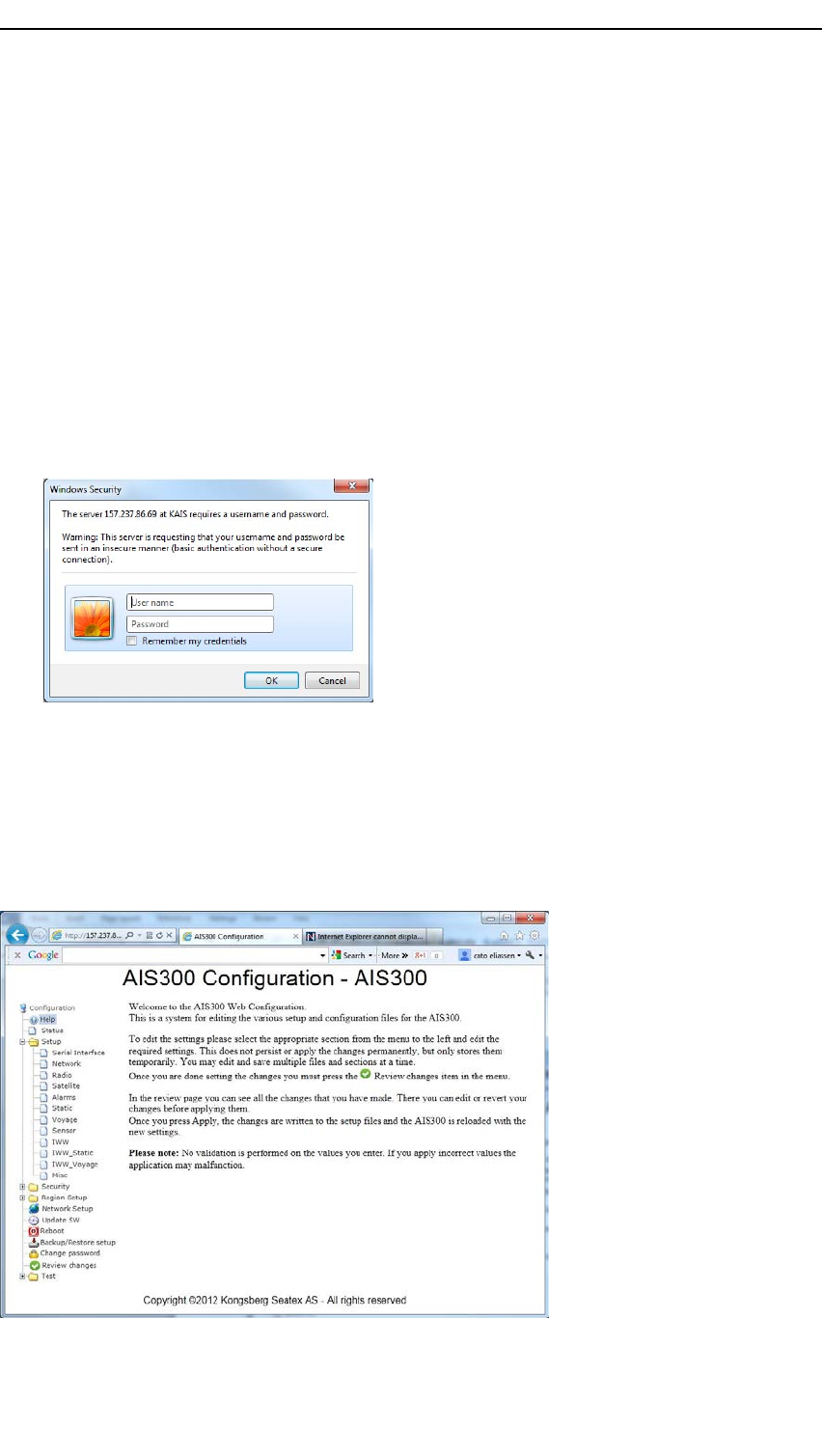
5.1.2.1ConnectingtoWEBinterface
HowtoconnecttotheWEBinterface
1Openabrowserandwrite:http://<ipadr>/intheaddressbar
2EnterthedefaultlogincredentialsforUser:ais
3EnterthedefaultlogincredentialsforPassword:1234
4ContinuewiththecongurationonceyouhaveenteredtheAISUnit.
5.1.2.2ChangingparametersviaWEBinterface
TheWEBinterfaceconsistsoffoldersforthevarioussettings,whichagainhave
sub-folders.Whenyouclickafolder,adialogboxwiththesettingsappears.Thisis
whereyouchangethesettings.
A300-02/2.041
Preliminary
KongsbergAIS300
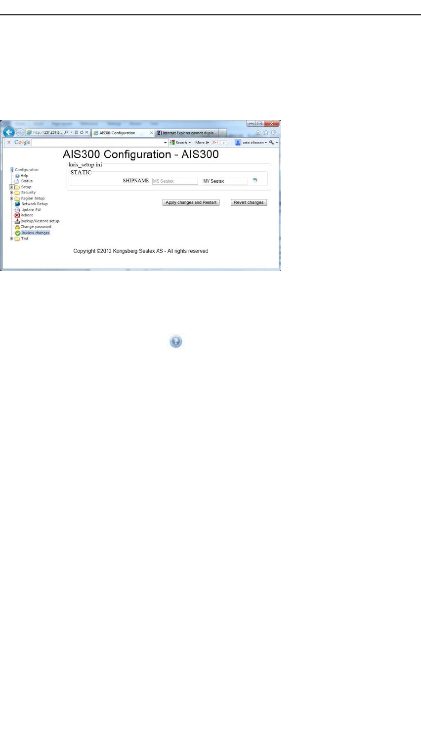
Whenyouhavemadethechanges,theyneedtobeconrmedbeforethechangestake
place.ThisconrmationiscarriedoutunderReviewchanges.Hereareallthechanges
listedandyouareaskedtoconrm.
5.1.2.3WEBinterfaceHelpfunction
AdescriptiononhowtousetheWEBinterfaceisavailablewhenconnectingtoanAIS
Unit.Inadditionthereisashortdescriptionlinkedtoallparametersthatarevisiblewhen
hoveringovertheparametername
.
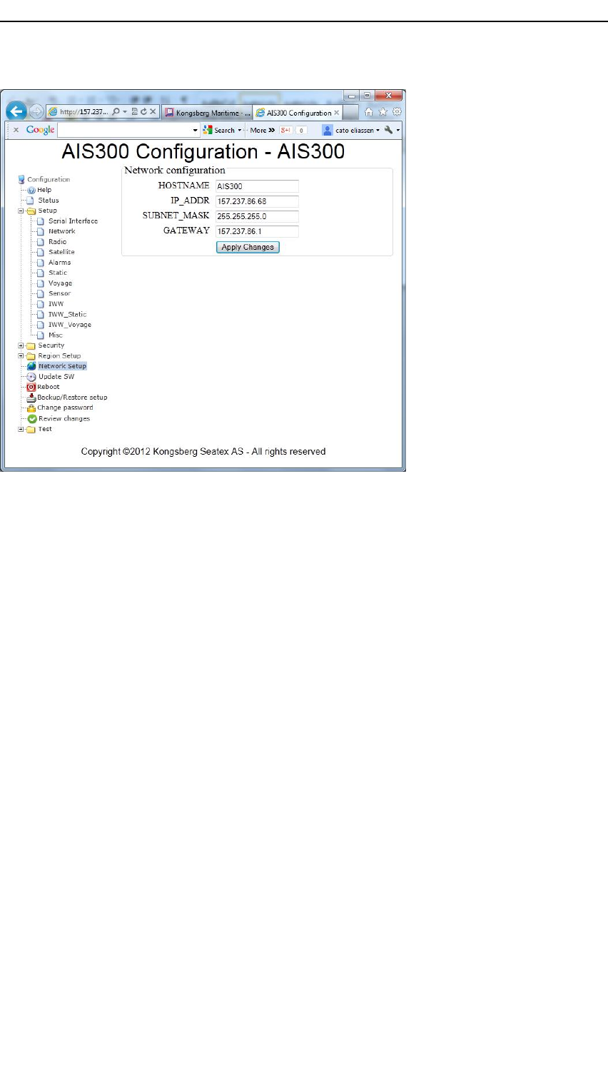
5.1.2.4RecongurationofIPaddressviaWEBinterface
ChangestotheIPaddress,subnetmask,gatewayandhostnamearelocatedunder
NetworkSetup.Asatypingerrorduringremotecongurationmightleadtolossofremote
access,specialcareshouldbetakenduringchangesofnetworkparameters.Theuserwill
beaskedtoapplychangesandawarningwillbegiven.Thesystemwillautomatically
redirecttheusertothecorrectaddressafterthechangeiftheuserisonthecorrectsubnet.
42A300-02/2.0
Preliminary
Conguration
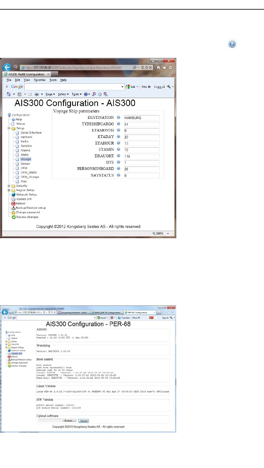
5.1.2.5Voyagerelateddata
Someparameterscanbechangedinconnectionwiththevoyageandthesevoyagerelated
datacanbeconguredunderSetup→Voyage.
Destination
DestinationshouldbeenteredinaccordancewiththeIMOSN/Circ244whichgives
guidanceforUN/LOCODE(Unitednation/LocationCode).20charactersareavailable
forthename.
Draught(static)
Draught(static)shallbeenteredindecimetersintheWEBinterface(115=11.5cm).To
beupdatedifthesalinityofthewaterortheweightofcargoischanged.
Typeofshipandcargo
Tablesforcategorizingof“shiptypes”aredenedinIMOSN/Circ227Guidelines
forinstallationofshipborneAIS.
•A“shiptype”isidentiedbyarstandseconddigittakenfromdifferenttablesin
theIMOstandard:
–TableACommercialvesselsnotengagedinspecialactivities,1digit#5says
“specialcraft”—seetableC
–TableCSpecialcraftengagedin“ofcial”activities,says2digit#5“Law
enforcementvessel”
–HenceaCGvesselsisidentied;1stdigit5,2nddigit5
A300-02/2.043
Preliminary
KongsbergAIS300
•Typicalshiptypescanbefoundwhenhoveringovertheparametername .
5.1.2.6SoftwareupdateviaWEBinterface
ThesoftwarecanbeupdatedviatheWEBinterface.AfterclickingUpdateSW,youwill
beaskedforalocationforthenewsoftware.Thesystemwillcheckthevalidityofthe
updatebeforethesoftwareisrestartedandtheupdatetakesplace.
ThesoftwarecanalsobeupdatedlocallyviaanUSBstick.
44A300-02/2.0
Preliminary
Conguration
Relatedtopics
•Softwareupdatesonpage56
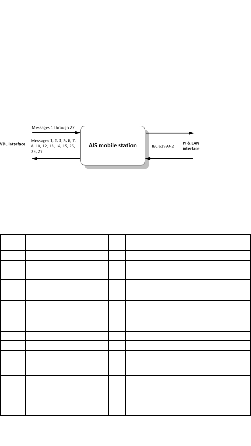
5.2Messagetypes
TheAISmobilestationsystemsupportsdifferentmessagesontheVHFdatalinkand
onthePIandLANinterfaces.TheillustrationshowsthemessageowatVDLand
PIonserialand/orLAN.
Afterstartup,thatistherstminuteaftertheAISUnitsoftwarehasstarted,thesystem
startstotransmitmessage1to3and5onaregularbasis.Thetransmitintervalis
dependentonspeedandturnratesformessages1to3.
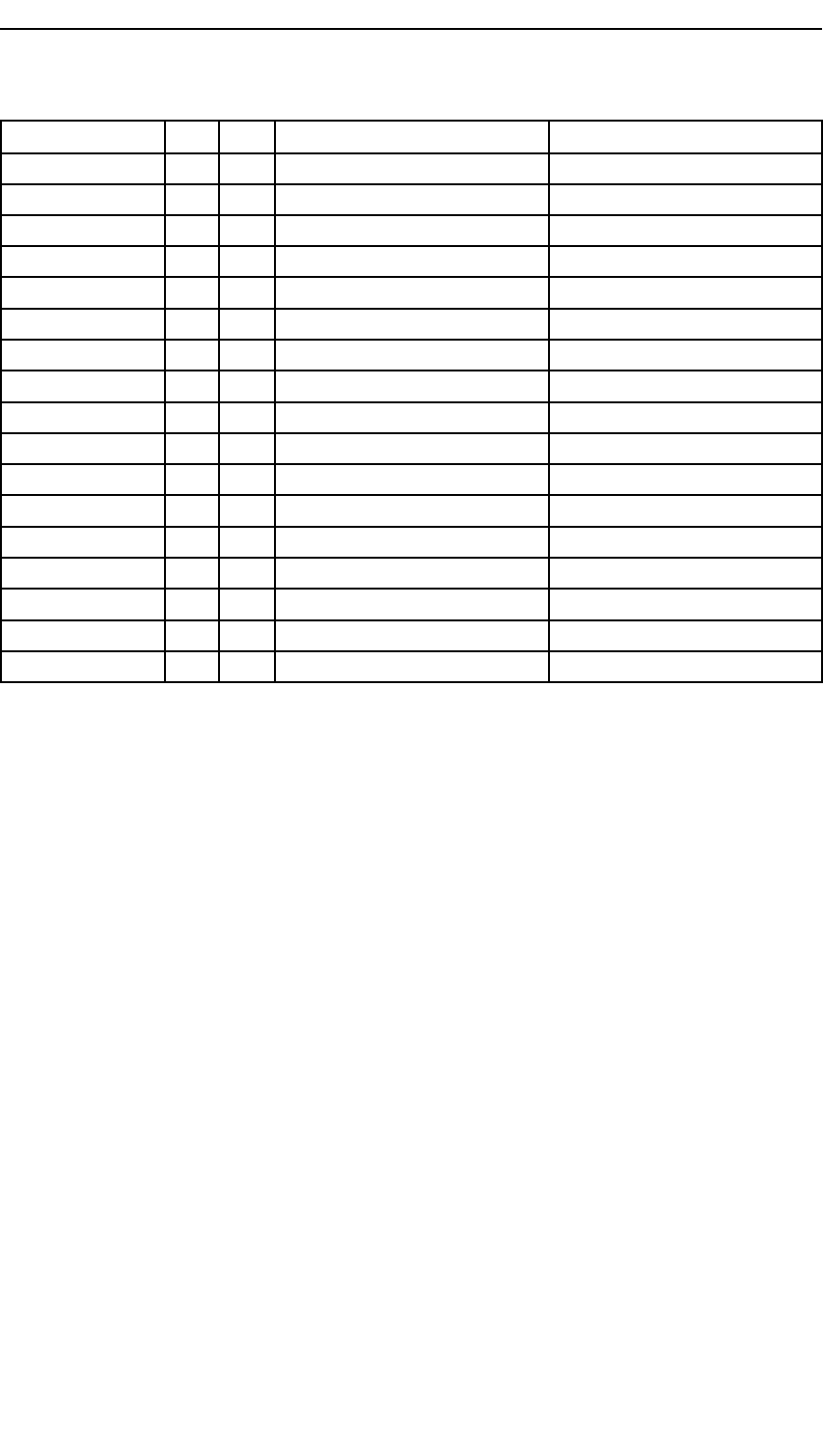
5.2.1VDLmessages
ViatheVDLinterfacethesystemcanreceiveortransmitthefollowingmessages:
Msg.
IdMessagenameRXTXDescription
1Positionreport••
2Positionreport••
3Positionreport••
4Basestationreport•Sentbetweenbasestationandtransponderor
betweenbasestations.Containsinformation
aboutposition,UTC,dateandslotnumber.
5Staticandvoyagerelateddata••
6Binaryaddressedmessage••Usedasnecessaryfortransmittingmessages
betweenbasestationandaddressedtransponder
andbetweenbasestations.
7Binaryacknowledge••Acknowledgeofmessage6.
8Binarybroadcastmessage••Sameas6,butthisoneisforbroadcast.
9StandardSARaircraftposition
report
•
10UTC/datainquiry••
11UTC/dataresponse•
12Addressedsafetyrelatedmessage••Usedasnecessaryfortransmittingsafetyrelated
messagesbetweenbasestationandaddressed
transponderorviceversa.
13Safetyrelatedacknowledge••Acknowledgeofmessage13.
A300-02/2.045

Preliminary
KongsbergAIS300
Msg.
IdMessagenameRXTXDescription
14Safetyrelatedbroadcastmessage••Sameas12,butthisoneisforbroadcast.
15Interrogation••Requestforaspecicmessagetype.Usedfor
requestfortransmissionofinformationfromone
systemtoanother.
16Assignmentmodecommand•Sendfrombasestationtotransponderassigning
timeslotandMSGtype.
17DGNSSbroadcastbinarymessage•Usedfortransmittingcorrectionsignalsfrom
thebasestationtotransponders.
18StandardclassBequipmentposition
report
•
19ExtendedclassBequipmentposition
report
•
20Datalinkmanagementmessage•GivesinformationtotransponderwhenMSG4
iscoming.
21Aids-to-navigationreport•
22Channelmanagement•Channelassignment,informationsentfrombase
stationtotransponderregardinguseofchannels,
outputpower,bandwidth,etc.
23Groupassignmentcommand•Assignmentofaspecicreportbehaviourby
competentauthorityusingaBasestationtoa
specicgroupofmobiles.
24Staticdatareport•AdditionaldataassignedtoanMMSI.
PartA:Name
PartB:Staticdata
25Singleslotbinarymessage••Shortunscheduledbinarydatatransmission
(broadcastoraddressed).
26Multipleslotbinarymessagewith
Communicationstate
••Scheduledbinarydatatransmission(broadcast
oraddressed).
27SATAISmessage•ShortAISmessagesentbyaClassAAISon
ChCandD.Canbereceivedifreceivingon
ChCandD.
5.3NMEAsentences
5.3.1PIsentences
ThesystemoutputsallreceivedVDLmessagesasVDMsentencesviathePILANand
PISerialport.DefaultisUDP/port4711andTCP/Port4712.
PIonTCPcanbeturnedoffunderSetup→MiscintheWEBinterfacebychangingthe
FULL_PI_TCPparameterto0.TheTCPportcanbechangedunderSetup→Networkby
changingtheLAN_PITCP_PORTparameter.Usevalueabove23.
46A300-02/2.0

Preliminary
Conguration
Inaddition,allVDLmessagestransmittedbythesystemareoutputasVDOsentences.
ALRsentencesareperiodicallyoutputonthesameinterfaces.Othersentencescanbe
outputdependingonconguration.
ViathePIinterfacethesystemcanreceiveortransmitsentencesaccordingtoIEC
61993–2.
ThetablecontainsinputandoutputmessagesonthePIinterface.AllNMEAelds
areused.
NMEASentenceRXTXDescriptionTransmissioninterval
ABK•AISaddressedandbinarybroadcast
acknowledgement
Uponreceptionofmessages7and
13,andwhensendingmessage15
ABM•AISaddressedbinaryandsafety
relatedmessage
ACA••AISchannelassignmentmessageOutputwhenchangeofstatusoron
query
ACK•Alarmacknowledge
AIQ•Queryforspeciedsentence
(AIQ,nmea)
AIR•AISinterrogationrequest
ALR•Setalarmstate30seconds/1min.
BBM•AISbroadcastbinarymessage
HBT••Heartbeat(BIIT)
LRI•Longrangeinterrogation
LRF••Longrangefunction
LR1•Longrangereplywithdestination
forfunctionrequestA
LR2•Longrangereplywithdestination
forfunctionrequestB,C,EandF
LR3•Longrangereplywithdestination
forfunctionrequestI,O,P,UandW
SSD••Shipstaticdata
TXT•TexttransmissionWhenchangeofstatus
VDM•AISVHFdata-linkmessageWhenreceivingmessageonVDL
VDO•AISVHFdata-linkown-vessel
report
WhensendingmessageonVDL
VER••V ersion
VSD••V oyagestaticdata
Proprietary:
PSTXQ,Queryrequestfor:
BRCADR•PILANBroadcastparameters
IMO•IMOnumber
MMSI•MMSInumber
OWNIP•CongureIPparameters
A300-02/2.047
Preliminary
KongsbergAIS300
NMEASentenceRXTXDescriptionTransmissioninterval
PORT•Serialportconguration
PSTXR,Responseonquery:
BRCADR•PILANBroadcastparameters
IMO•IMOnumber
MMSI•MMSInumber
OWNIP•CongureIPparameters
PIWWSSD•Inlandwaterwaystaticshipdata
PIWWVSDInlandwaterwayvoyageshipdata
PORTSerialportconguration
PSTXS,Set:
BRCADR•PILANBroadcastparameters
IMO•IMOnumber
MMSI•MMSInumber
OWNIP•CongureIPparameters
PIWWSSD•Inlandwaterwaystaticshipdata
PIWWVSD•Inlandwaterwayvoyageshipdata
PORT•Serialportconguration
5.3.1.1STXAIS,proprietaryinternalinformationsentence
Thissentenceisdefaultoutputatstart-upoftheAISUnit.Inadditionitcanbeoutput
atacongurableintervalbutdefaulteach120seconds.Youcanrequestthemessage
withaNMEAsentence.TorequesttheinternalAISinformation,thefollowingcan
besentonthePI.
Format
$PSTXQ,STXAIS*<FCS><CR><LF>
TheAISBSresponsemessagehasthisformat(onemessageperport):
Format
$PSTXR,STXAIS,<type>,<version>,<uptime>,<radiostat><fwp>,
<rfp><threadstatus>,<systemstatus>,<low
synth>*<FCS><CR><LF>
Formatdescription
1STXAIS=MessageIDidentifyingthissentence
2type=HexvaluedescribingthetypeofAISUnit
3version=Firmwareversion
4uptime=Uptimesincelastrebootdddhhmm
5radiostat=Hexvalueradiostatus
48A300-02/2.0

Preliminary
Conguration
6fwd=Forwardpower
7rfp=Reectedpower
8threadstatus=Hexvalueofthreadstatus.Thethreadthatcausedwatchdogtotrig
9systemstatus=Hexvalueofthesystemstatus.Reasonforlastreboot
10lowsynth=Thedatareadwhenthelowersynthisselected
ThefollowingarenotusedinthisAISproduct:
•<radiostat>
•<lowsynth>
•Always<0>
5.3.1.2VDMsentencestructure
ThestructureforaVDMsentencecanbeasfollows:
•!AIVDM,1,1,,B,13n324wP000gWlhTCDQN4?vD00Sb,0*1B
The!signindicatesthatthesentenceisin6-bitNMEAbinaryformat,whichisnota
directreadableformat.InthisexampletheAIVDMindicatesthatthisisdatareceived
fromanotherunit.TheBindicatesthatthemessageisreceivedonAISchannelB.
5.3.1.3ALRsentencestructure
ThestructureforanALRsentencecanbeasdescribedbelow:
•$AIALR,150517.00,032,A,V ,AIS:headinglost/invalid*27
The$signindicatesthatthisisanASCIItextsentencewhereitispossibletoreadsome
oftheinformationdirectly.Typicaluseofthissentencetypeisforthealarminformation.
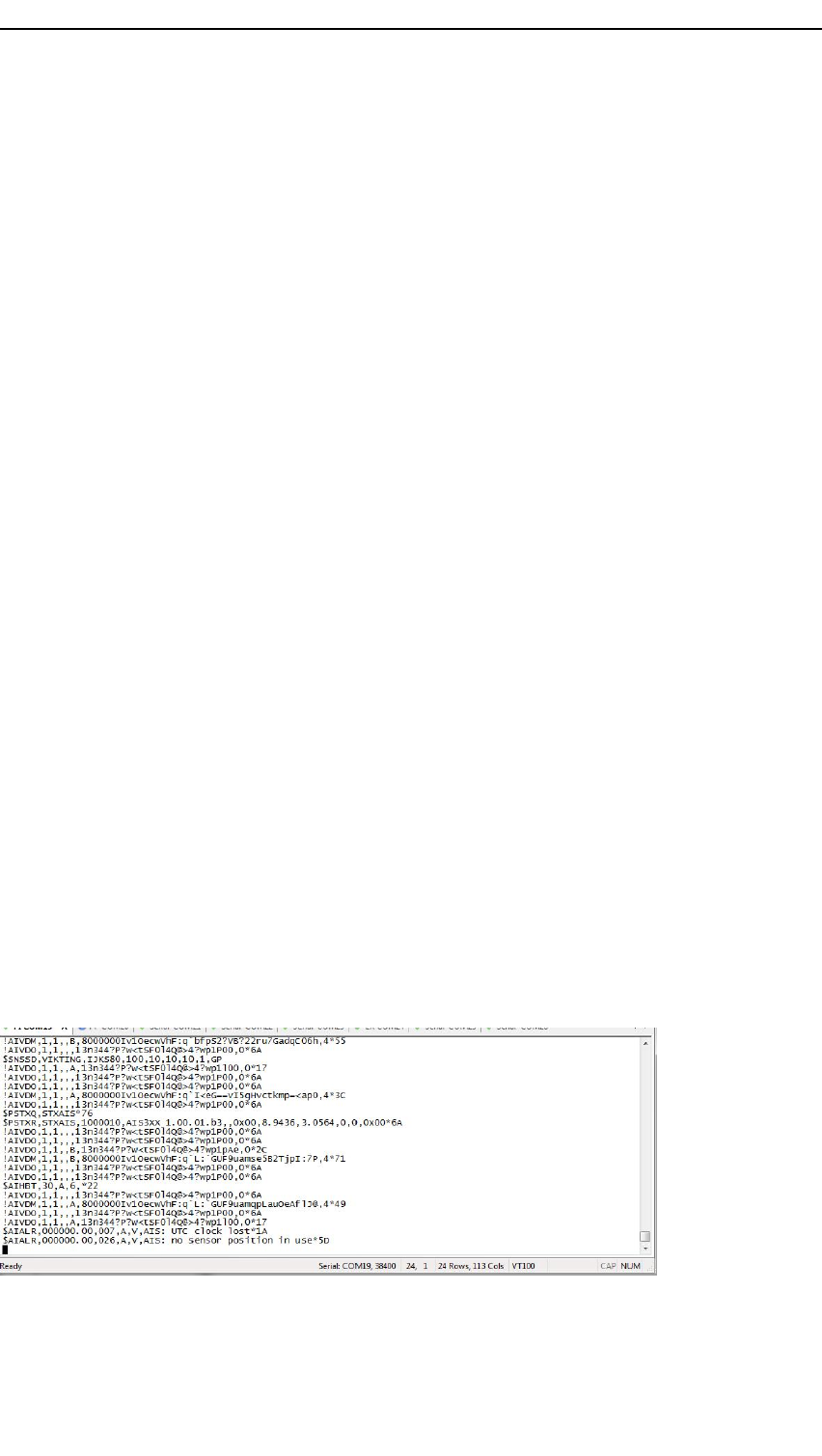
TypicaldataoutputviathePIserialorLANportcanbeasfollows:
•!AIVDM,1,1,,B,13n324wP000gWlhTCDQN4?vD00Sb,0*1B
•!AIVDO,1,1,,,13n31uOP000gWljTCDQN4?vH0000,0*1E
•$AIHBT,30,A,1,*25
•!AIVDM,1,1,,B,4h2MBmAupFaH<0gWljTCDQO0087K,0*31
•!AIVDO,1,1,,,13n31uOP000gWljTCDQN4?vJ0000,0*1C
•!AIVDM,1,1,,C,8000000Iv1OecwVhF:q`p`8d=b7n8CtegGvCs6i`WP,4*05
•$AIALR,083346.00,030,A,V ,AIS:novalidCOGinformation*4A
•$AIALR,150517.00,035,A,V ,AIS:novalidROTinformation*40
•$AIALR,150517.00,032,A,V ,AIS:headinglost/invalid*27
•$AIALR,150517.00,025,A,V ,AIS:externalEPFSlost*2A
•!AIVDO,1,1,,,13n31uOP000gWljTCDQN4?vT0000,0*02
•!AIVDM,1,1,,A,13n324wP000gWlhTCDQN4?vV059P,0*57
•!AIVDM,1,1,,A,4h2MBoiupFaHCPgCF0TBHl70059P,0*33
•!AIVDO,1,1,,,13n31uOP000gWljTCDQN4?vb0000,0*34
•!AIVDO,1,1,,,13n31uOP000gWljTCDQN4?vd0000,0*32
A300-02/2.049
Preliminary
KongsbergAIS300
•!AIVDM,1,1,,A,4h2MBmAupFaHF0gWljTCDQO0059P,0*50
•!AIVDO,1,1,,,13n31uOP000gWljTCDQN4?vf0000,0*30
•!AIVDO,1,1,,,13n31uOP000gWljTCDQN4?vh0000,0*3E
•!AIVDM,1,1,,C,13oChT0001Pg`p6TCDD6GPP`00S2,0*41
Datacanbedecoded/replayedandveriedusinganexternalsystemthatiscapable
ofreadingthedata.
Therearetwotypesofalarmmessageswhichconsistoftwodifferentsentences.These
aretheTXTandtheALRsentences.TheTXTindicatesachangeinstatusofsome
operationalparameters,andtheALRinformsofanerrorsituationthatmightneed
correctiveaction.
Note
HeadingvalidwilloccurasTXT(info)whenreceivedrsttimeafterstart-up.Iflost
again,thealarmwillbevaliduntilitoccursoruntiltheunitisrestarted.
5.3.2Sensorsentences
Themainintentionofthesensorportistoreceiveinputfromanexternalsystem.Such
systemscouldbeanexternalGPSsource.TheinputmessagesontheSensorinterface
areaccordingtothetable.
NMEA
SentenceRxTxDescriptionTransmissioninterval
DTM•Latoffset,Lonoffset,altitudeoffsetnot
used.
GBS•GNSSsatellitefaultdetection
GGA•Globalpositioningsystemxdata
GLL•Geographicposition–latitude/longitude
GNS•Navstatusindicatornotused.Meansea
levelnotused.Antennaaltitudenotused.
HDT•Heading
RMC•RecommendedminimumspecicGNSS
data.Navstatusnotused.
ROT•Rateofturn
THS•Heading
VBW•Sternwaterspeedandsterngroundspeed
parametersarenotused.
VTG•Courseovergroundandgroundspeed
ZDA•Timeanddata
5.3.2.1Priorityofposition
ThesystemwillprioritizetheuseofNMEAsentencesinaccordancewiththeposition
prioritytable.
50A300-02/2.0

Preliminary
Conguration
PrioritySentence
1RMC
2GNS
3GGA
4GLL
5.3.2.2Prioritybetweensensors
ThereisanautomaticpriorityofwhichpositioninputtheAISmobilestationwill
transmit.Theprioritylistisasfollows:
1Externalsensorinputofdifferentialcorrectedposition.
2Internalsensorinputofdifferentialcorrectedposition.
3Externaluncorrectedposition.
4Internaluncorrectedposition.
5.4Differentialcorrections
ThesystemcanreceiveRTCM2.3DGPScorrectionsontheRTCMserialport(RS-422).
Itwillautomaticallyenterdifferentialmodewhencorrectionsarereceived,giventhat
thecorrectionsarevalid.
A300-02/2.051

Preliminary
KongsbergAIS300
6Gettingstarted
Thischapterdescribesthemainoperatingproceduresforgettingstartedandusingthe
AISUnit.
6.1HowtoturnontheAISUnit
1Ensurethattheserialconnection(s),thenetworkandtheantennasareconnected.
2Insertthepowerconnectorwith12to24VDC.
3Afterapproximately30secondstheLEDswillstarttoash.TheGPSLEDwill
starttoashaftertheinitialisation.Theinitialisationperiodmaytakeupto15
minutes,dependingontheGPSalmanac.Itwillchangefromyellowtogreenwhen
theinitialisationperiodisover.
Relatedtopics
•LEDindicatorsAISUnitonpage27
6.2AISUnitsettings
ThefollowingsettingsmustbecarriedoutinordertogetaworkingAISUnit.We
recommendtocarryoutthesesettingsviatheWEBinterface.RefertoCongurationon
page40onhowtousetheWEBinterface.
6.2.1Networksettings
Howtochangethenetworksettings
1Connectthenetworkport(AISLAN)oftheAISUnittoaPC,networkswitchor
hub.TheunitisdeliveredwithdefaultIPaddress.
2Typetheaddress:http://<ip-address>toconnecttotheWEBinterfaceof
theAISmoduleforconguration.DefaultIPaddressis:10.0.21.60.
3OryoucanuseNMEAsentencesforcongurationoftheAISmodule.
52A300-02/2.0
Preliminary
Gettingstarted
Relatedtopics
•RecongurationofIPaddressviaWEBinterfaceonpage42
•CongurationviaWEBinterfaceonpage41
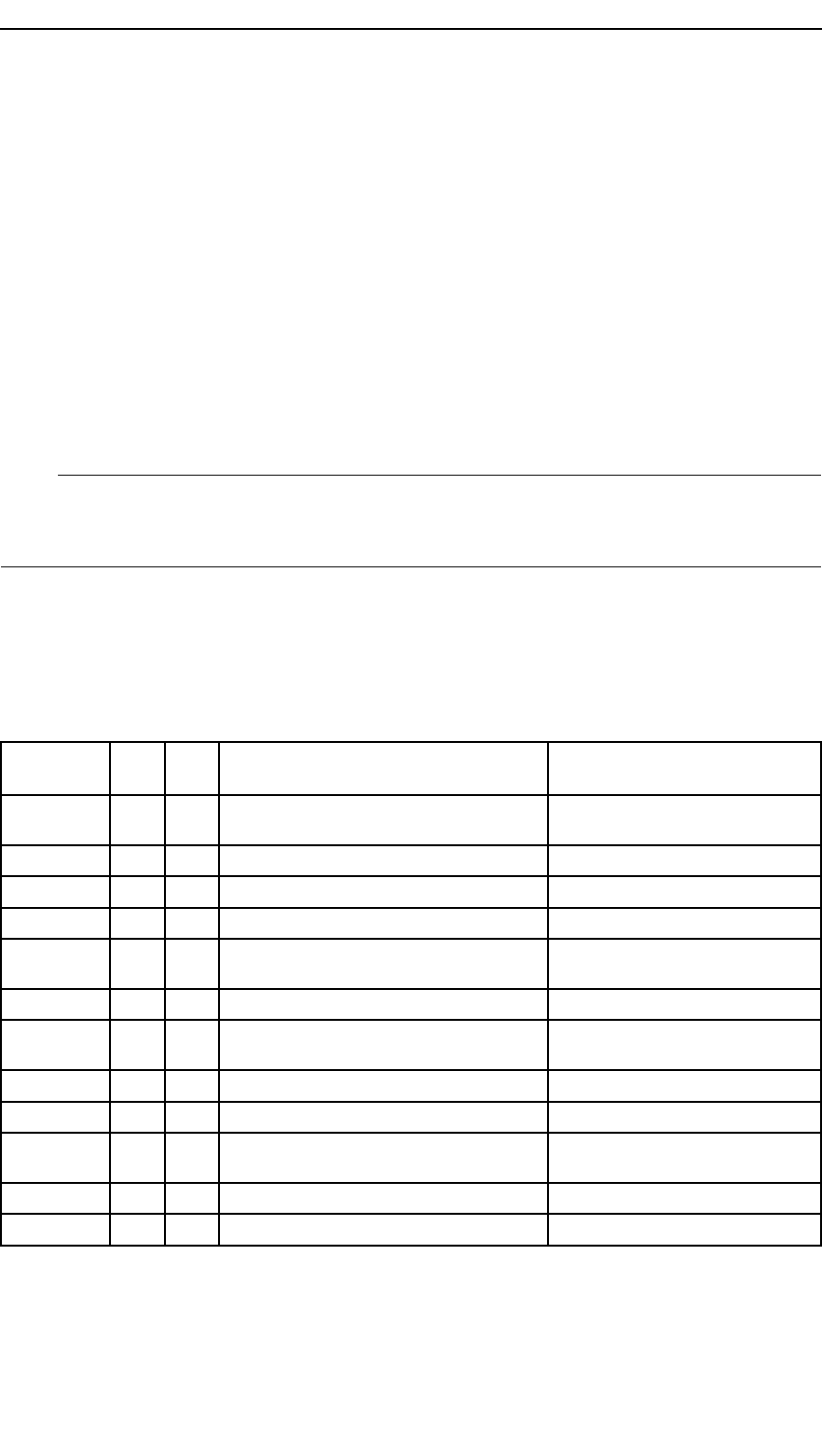
6.2.2Staticparameters
AsfaraspossibletheAISmobilestationispre-congured.Therearesomeparameters
thatneedtobesetinconnectionwiththeinstallation.ThesearecollectedunderSetup
→Static.StaticdatashouldnormallynotchangeafterinstallingtheAISUnit.
Remembertocontrolthattheenteringofthestaticdataisproperlycompleted.The
installationpersonnelshouldcongurethestaticdataasapartoftheinstallation.Ship
personnelshouldbeavailablewhencongurationisexecutedinordertoprovidecorrect
vesseldatasuchasMMSI,IMOnumberetc.
MMSI
TheMMSInumberisdefaultsetto0.TheunitwillnottransmitbeforeavalidMMSI
numberiscongured.
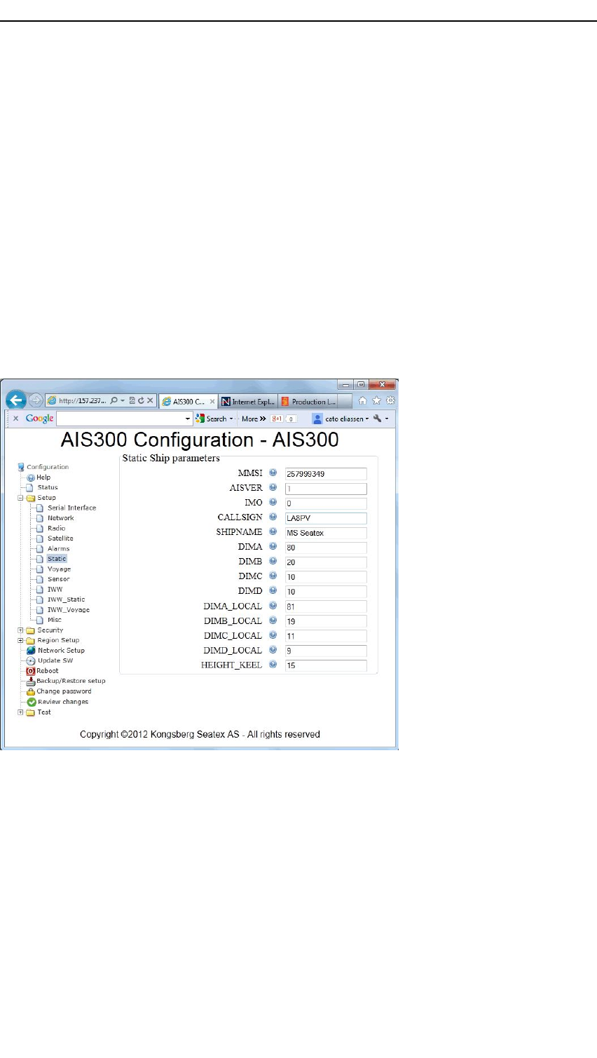
DIMA
ExternalGPSantennalocation.Inmetres.
DIMA_LOCAL
AISinternalGPSantennalocation.Inmetres.
A300-02/2.053
Preliminary
KongsbergAIS300
HEIGHT_KEEL
Vesselheightoverkeelinmeters;Totalheightfromkeeltotopofmast.
6.2.3Radio—VHFchannelsandpower
DefaultVHFRXandTXchannelsarethestandardAISchannels.ChCisdefaultoff.
Powerlevelisdefault12W.ParameterscanbesetbysendingaBCFsentencetotheAIS
Unit.TheseparameterscanalsobesetintheWEBinterfaceunderSetup→Radio.
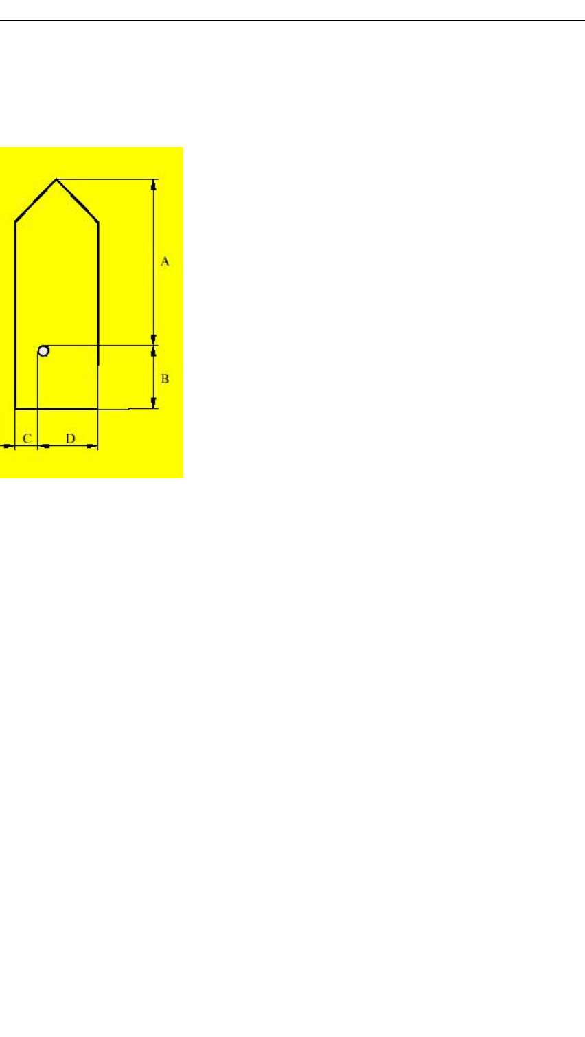
6.3Statusinformation
TheStatuspageintheWEBinterfaceholdsinformationonAlarms(ifany),Statusand
StationList.
Alarms,ifany,arelistedinadditiontoownposition(internalGNSSpos).TheStation
ListgivesthenumberofvisibleAISvesselsandthedistancetothemostdistantunit.
VSWR,ForwardedandReectedpoweraredisplayedintheStatusbox.
54A300-02/2.0

Preliminary
KongsbergAIS300
7Maintenance
TheAISsystemconsistsofbothsoftwareandhardware.Thesoftwarepartcanbe
reinstalledorupgradedtothelatestversionintheeld.Serviceonthehardwarein
theeldcanconsistof:
•ExchangingdamagedGNSSantennacables.
•ExchangingfailedGNSSantenna.
•ExchangingdamagedVHFantennacables.
•ExchangingfailedVHFantenna.
•ExchangingfailedAISUnit.
TheAISUnitisnotdesignedforserviceintheeldandopeningthehousingcanresult
indamageordegradationoftheunitandvoidthewarranty.
7.1Periodicmaintenance
Someactivitiesshouldbecarriedoutonaregularbasistomaintaintheconditionor
operationalstatusoftheequipment.
7.1.1Antennacare
Theenclosuresshouldbecarefullycleanedonaregularbasiswithadampclothandmild
soap.Brushoffanyiceorsnowtoensureoptimalperformance.
Note
Donotuseabrasivecleanersorchemicals.
7.2Softwareupdates
KongsbergSeatexASwillregularlyoffersoftwareupgradesfortheAISUnitwith
improvementsandnewfunctionalities.Itisuptotheusertodecidewhetherhewill
updatehis/herunittothelatestversion.Contactcustomersupporttoreceivethenew
software.
56A300-02/2.0

Preliminary
Maintenance
7.2.1Softwareupdateroutine
SoftwareontheAISmodulewithintheAISUnitcanbeupdatedeitherremotelyfrom
aPC(viaWEBinterface)orlocally(viaUSBdevice).
HowtoupdatesoftwareviaUSB
1InserttheUSBdevicewiththeunzippedsoftwareupdateintheUSBport.
Note
NotallUSBdevicesaresupported.
2WhentheAISUnitdetectsanewrmwareontheUSBdeviceitwillbevalidated
anduploaded.
3Theunitgoesthroughanupdateprocedureandrestartstheprocesseswhichare
affectedbytheupdate.
4WhentheupdateisnishedtheAISUnitwillenterstandardoperationmodebased
onthesettingsithadbeforetheupdate.
Relatedtopics
•SoftwareupdateviaWEBinterfaceonpage44
7.3Repairsandmodications
RepairoftheAISUnitcanconsistof:
•exchangingdamagedantennacables
•exchangingfailedantennas
•exchangingtheAISUnit
Theserepairscanbecarriedoutbyaskilledelectrician.
7.3.1Exchangeofantennacable
Howtochangeantennacable
Caution
Iftheantennacableisattachedtotheunit,donotattachtheantenna
cabletotheantennawiththeAISUnitpoweredon.Iftheantennacableis
short-circuitedwithpoweron,thereceiverorAISmodulewithintheunit
canbedamaged.
1TurnofftheAISUnitbydisconnectingthepowerconnectorfromtheAISUnit.
2Dismountthedamagedantennacable.Thenewantennacablemustbeasstraightas
possible.Donotcrushorcrimpthecableasthiswillaffecttheelectricalproperties
ofthecable.
3Connecttheantennacabletotheantenna.
A300-02/2.057
Preliminary
KongsbergAIS300
4Theconnectionbetweentheantennaandtheantennacableshouldbesealedagainst
waterpenetration,preferablyusingwaterproofself-vulcanizingtape.
5ConnecttheantennacabletotheAISUnit.
7.3.2Exchangeofantenna
Howtochangeantenna
Caution
Iftheantennacableisattachedtotheunit,donotattachtheantenna
cabletotheantennawiththeAISUnitpoweredon.Iftheantennacableis
short-circuitedwithpoweron,thereceiverorAISmodulewithintheunit
canbedamaged.
1TurnofftheAISUnitbydisconnectingthepowerconnectorfromtheAISUnit.
2Dismountthefailedantenna.
3Mountthenewantennaonthemountingrodorsimilar.
4Connecttheantennacabletotheantenna.
5Theconnectionbetweentheantennaandthecableshouldbesealedagainstwater
penetration,preferablybyusingwaterproofself-vulcanizingtape.
6ConnecttheantennacabletotheAISUnit.
7.3.3RepairofAISUnit
Allrepairsandmodicationsoftheunit,exceptfrominstallationofnewsoftware
versionsandsetupofthesystem,shouldbecarriedoutbyqualiedpersonnel.Afailed
unitshouldbeshippedbacktoKongsbergSeatexASorotheragreedservicepointfor
repair.BoardchangesshallonlybeconductedinagreementwithKongsbergSeatexAS
servicepersonnel.
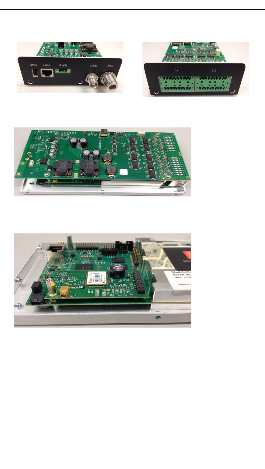
7.3.3.1Changingtheinterfaceboard
Howtochangetheinterfaceboard
1DisconnectallcablesandplacetheAISunitonatableinEMCsafeconditions.
2Removethethreescrewsoneachsideofthetopcoverandliftitoff.
58A300-02/2.0
Preliminary
Maintenance
3Dismountthetwosideplatesbyremovingthetwoscrewsoneachside.
4Removethefourscrewsholdingtheinterfaceboardandlifttheboardoff.Itis
stackedontopoftheAISmoduleandsomewrigglingwillbenecessary.
5MountthenewinterfaceboardontopoftheAISmodule.
6Refastenthesideplatesandthetopcover.
7.3.3.2ChangingtheGPSboard
HowtochangetheGPSboard
1DisconnectallcablesandplacetheAISunitonatableinEMCsafeconditions.
2Removethethreescrewsoneachsideofthetopcoverandliftitoff.
3Dismountthetwosideplatesbyremovingthetwoscrewsoneachside.
A300-02/2.059
Preliminary
KongsbergAIS300
4Removethefourscrewsholdingtheinterfaceboardandlifttheboardoff.Itis
stackedontopoftheAISmoduleandsomewrigglingwillbenecessary.
5Whentheinterfaceboardisoff,disconnecttheGPSantennaconnectorandremove
thespacerholdingtheGPSboard.
6LifttheGPSboardofftheconnector.
7ExchangetheGPSboardwiththenewboard.
8FastentheboardwiththespacerandconnecttheGPSantennacable.
9PlacetheinterfaceboardontopoftheAISmoduleandrefastenthescrews.
10Refastenthesideplatesandthetopcover.
7.3.4InstallationofspareAISUnit
Ifaspareunitisrentedwhileyourunitisinforrepair,itisdeliveredwiththelatest
versionoftheproductsoftware.
HowtoinstallaspareAISUnit
1TurnofftheAISUnitbydisconnectingthepowerconnectorfromtheAISUnit.
60A300-02/2.0

Preliminary
Maintenance
2Disconnecttheunittoberepairedfromitscablesandreplaceitwiththespareunit.
3Connectallcablesastheywereontheoriginalunit.
4Poweruptheunit.
7.4Troubleshooting
Thispartofthedocumentiswrittenforpersonnelwithoperatorexperiencewhena
situationariseswhereassistancefromservicepersonnelmayberequired.Theaimof
thissectionistoidentifytheproblemsothattheappropriateactioncanbetaken.
7.4.1Systemstatus
Theerrorconditionsinthesystemareusuallyobservedbylookingatthecolourcodes
ofthefourLEDindicatorslocatedonthefrontpanelorintheStatuspageoftheWeb
interface.
WhencontactingKongsbergSeatexASsupport,pleaserefertotheserialnumberofthe
unitandthesoftwareversion.ThesoftwareversionnumbercanbefoundintheWeb
interface→UpdateSW.
Relatedtopics
•LEDindicatorsAISUnitonpage27
•Statusinformationonpage54
7.4.2Nopower
Whenpoweringontheunit,theLEDswillstartnormaloperationafterapproximately30
seconds.
IftheLEDindicatorsarenotlit,checkthepowerconnectiontotheunit.
7.4.3Externaloutputproblems
Duringoperationsituationsmayoccurwheretheexternalequipmentreceivesnodata
fromtheAISUnit.
WhattocheckifexternalequipmentreceivenodatafromtheAISUnit
1Checkthenetworkcables/equipment,seriallines(ifused),cables,cableconnectors
andantennasformechanicaldamage.
2CheckthattheconnectorsareconnectedtothecorrectoutputportsbothontheAIS
Unitandontheconnectedequipment.ThepinningisshowninInterfacesAIS
Unitonpage25.
3IfthecableandconnectorsareOK,checkthattheoutputcongurationoftheAIS
Unitissetupcorrectly.
A300-02/2.061


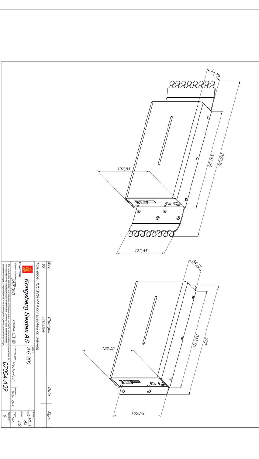
Preliminary
KongsbergAIS300
8.1AISUnitdimensions
64A300-02/2.0
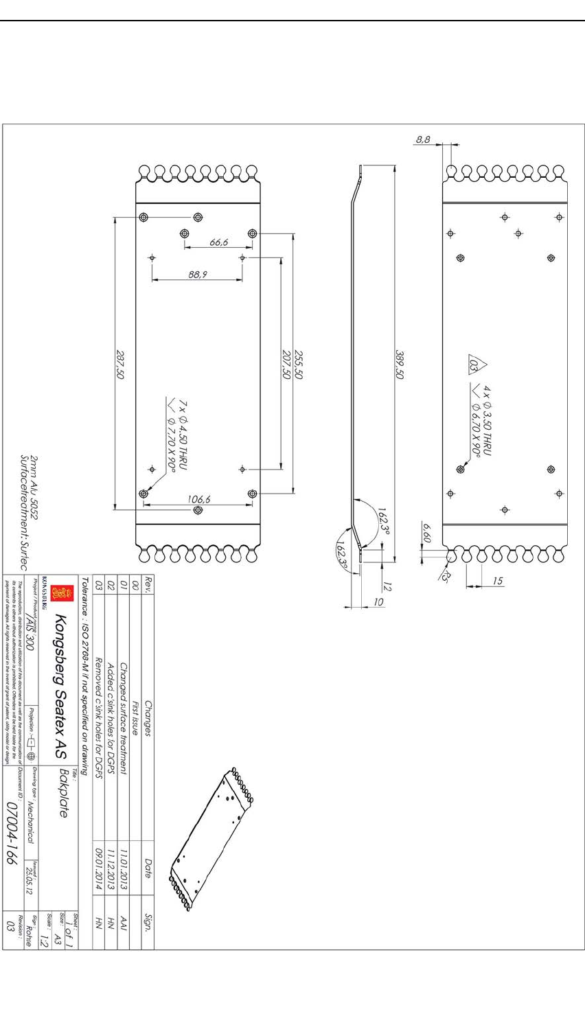
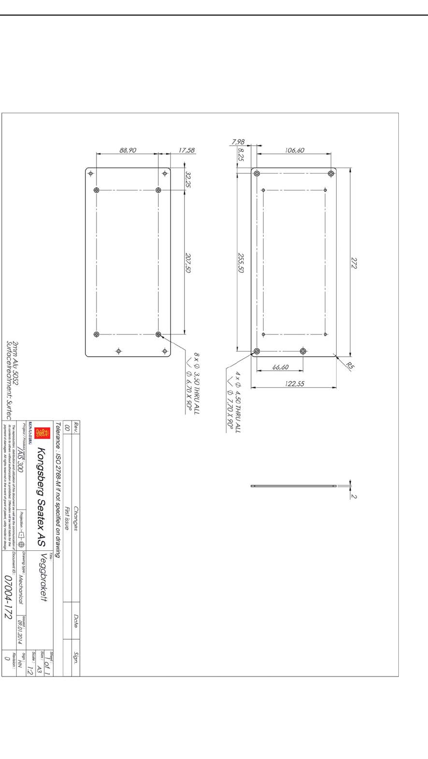
Preliminary
KongsbergAIS300
8.3Wallmountingbracketdimensions
Thiswallmountingbracketisoptionalandnotpartofthestandarddelivery.
66A300-02/2.0
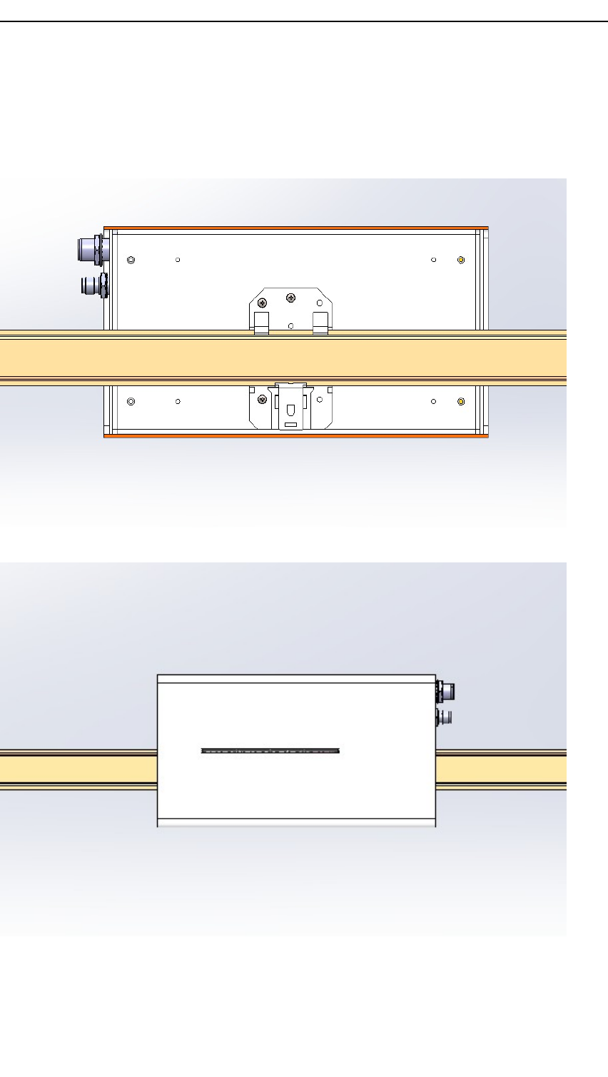

Preliminary
KongsbergAIS300
9Partslist
9.1Standardcomponents
PartnumberDescription
A300-01KongsbergAIS300mobilestation
A101-01GPSantenna,GPS4
A101-02_H*)MountingkitforGPS4
A100-58VHFantenna,A V7N
A300-02InstructionManual,AIS300
A300-03**)Connectorsetforserialandpower
A300-04Bracketwithstrainrelief
A300-08***)AIS300pilotplug
*)A101-02_H(MountingkitforGPSantenna)consistsof:
•A101-02(MountingbracketforGPS4)
•A101-03(InterconnectioncableforGPS4antenna,withN-female)
•A100-93(CablemainunittoGPSantennacable,withN-female,0.5m)
**)A300-03consistsof4x10pinconnectorforthegreenPhoenixconnectorsandone
2–pinpowerconnector.
***)Withbracket,nocable.ForplugwithcableorderA300–07.
9.2Systemaccessories
PartnumberDescription
A100-59GPS/VHFantennacable(RG–214),priceperm,maximumlength
30m
A100-60GPS/VHFantennacable(lowloss),priceperm,maximumlength
100m
A100-71ConnectorkitforGPSantennacable(lowloss),twoconnectors
A100-73ConnectorkitforVHFantennacable(lowloss),twoconnectors
68A300-02/2.0

Preliminary
Partslist
PartnumberDescription
A100-61ConnectorkitforGPSantennacable(RG–214),twoconnectors,
(1ea.)
A100-66ConnectorkitforVHFantennacable(RG–214),twoconnectors,
(1ea.)
G071-91CablemainunittoVHFantennacable,0.5m,(1ea.)
A101-03InterconnectioncableforGPS4antenna,withN-female,(1ea.)
A100-93CablemainunittoGPSantennacable,withN-female,0.5m,(1ea.)
A101-02MountingbracketforGPS4,(1ea.)
A300-05Wallmountbracketwithoutstrainrelief
A300–06DINrailbracketforDINrailmounting
A300–07Pilotplugwith10–metrecable
A300-02/2.069

Preliminary
KongsbergAIS300
10References
Referencedocuments
1NMEA0183StandardforInterfacingMarineElectronicDevices,Version3.00
2RTCMRecommendedStandardsforDifferentialNavstarGPS/GLONASSService,
Version2.3
3Technicalcharacteristicsforanautomaticidenticationsystemusingtime-division
multipleaccessintheVHFmaritimemobileband,RecommendationITU-R
M.1371-5
4Maritimenavigationandradiocommunicationequipmentandsystems-Automatic
identicationsystems(AIS)-Part2:ClassAshipborneequipmentoftheautomatic
identicationsystem(AIS)-Operationalandperformancerequirements,methods
oftestandrequiredtestresults,IEC61993–2,ed2.0
5Maritimenavigationandradiocommunicationequipmentandsystems-Digital
interfaces-Part1:Singletalkerandmultiplelisteners,IEC61162–1,ed4.0
6CharacteristicsofaTransponderSystemUsingDigitalSelectiveCallingTechniques
ForUseWithV esselTrafcServicesandShip-To-ShipIdentication,ITU-RM.825
70A300-02/2.0

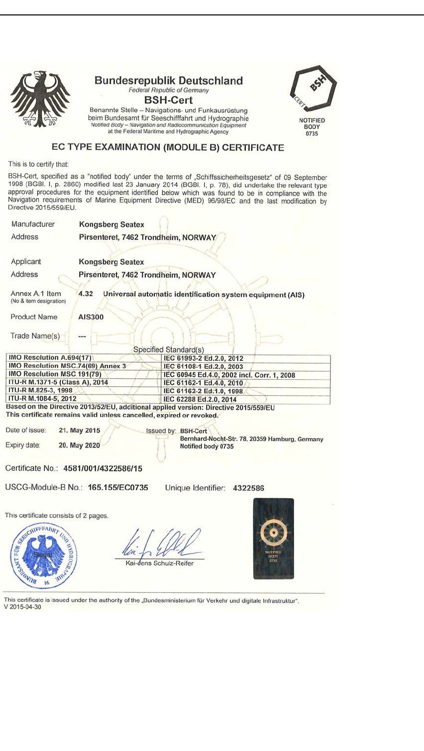
Preliminary
KongsbergAIS300
72A300-02/2.0
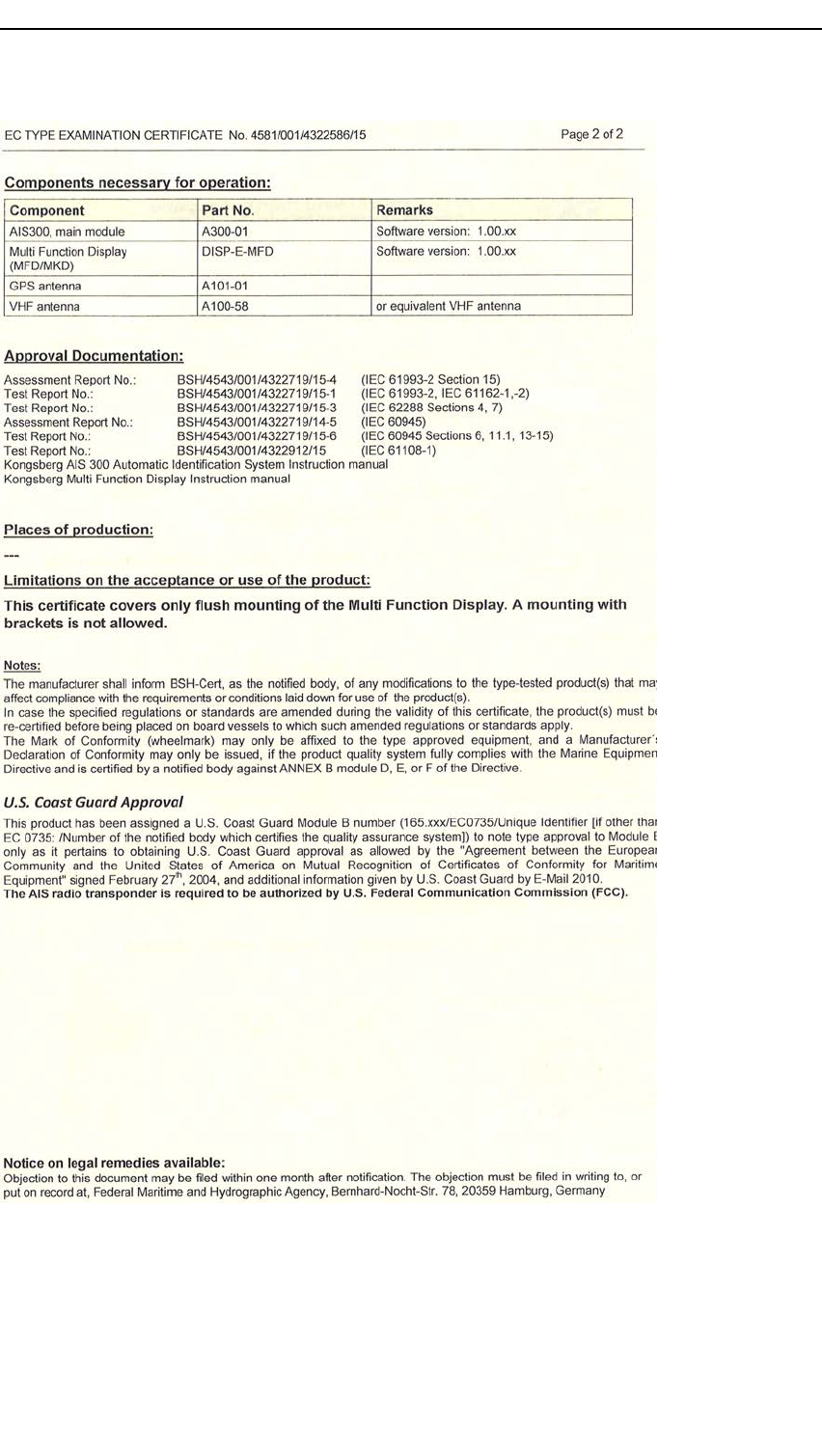
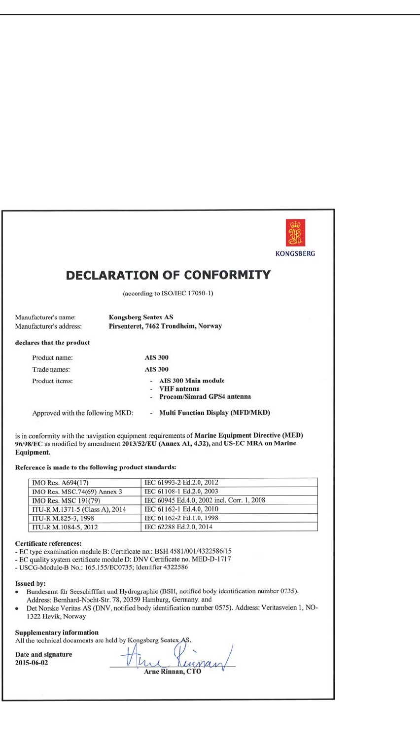
Preliminary
KongsbergAIS300
AppendixB
Declarationofconformity
74A300-02/2.0

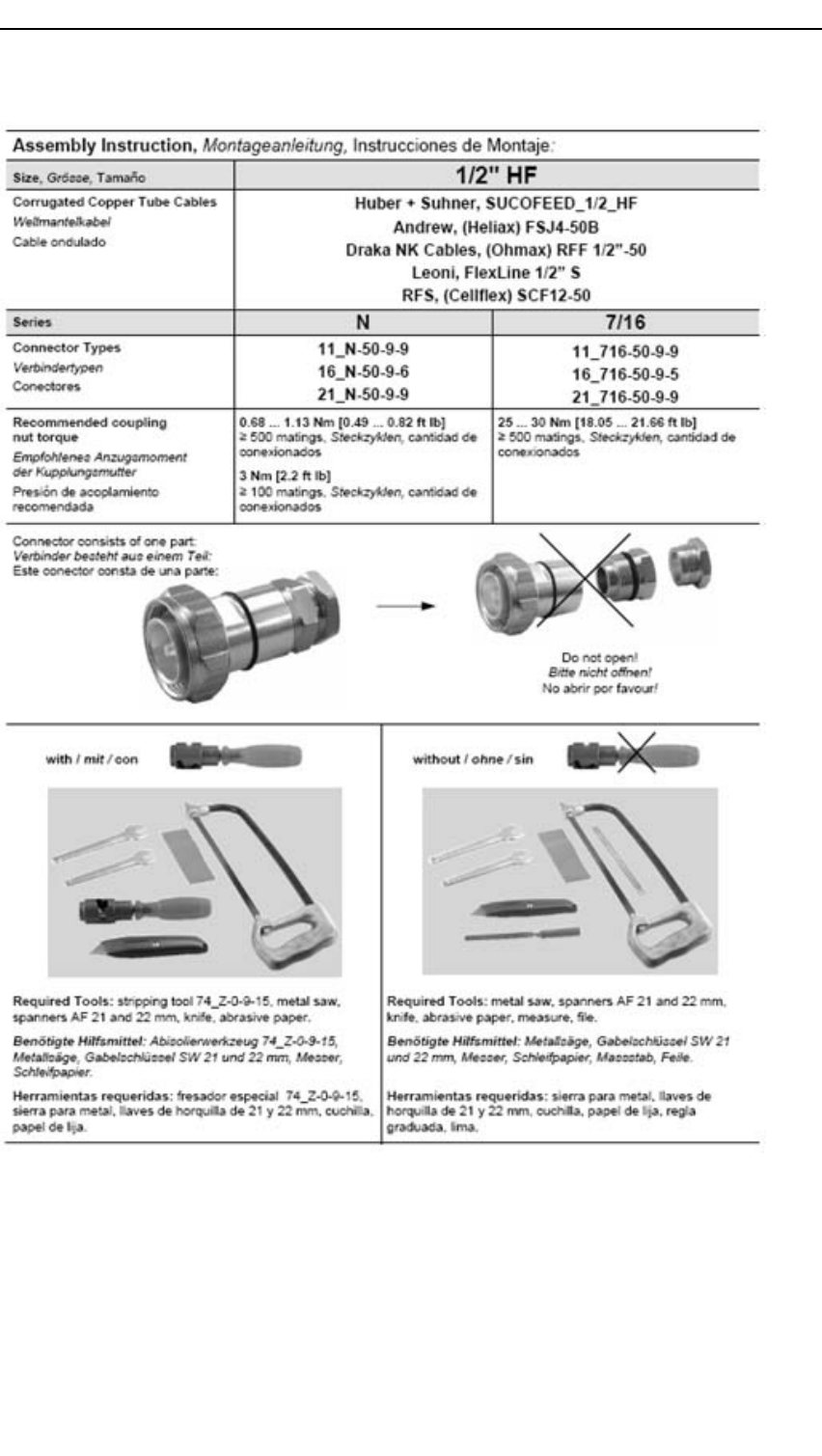
Preliminary
KongsbergAIS300
76A300-02/2.0
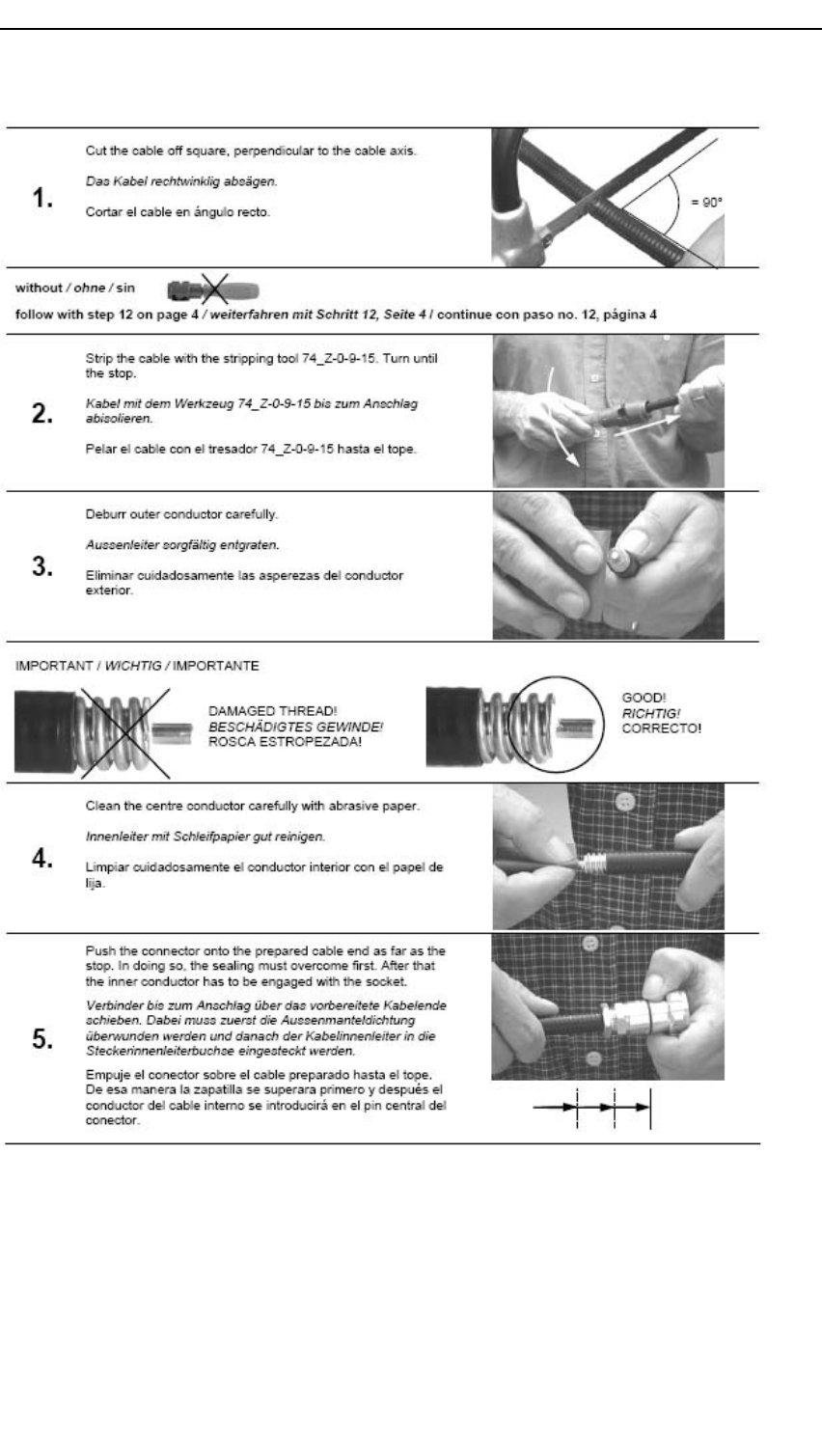
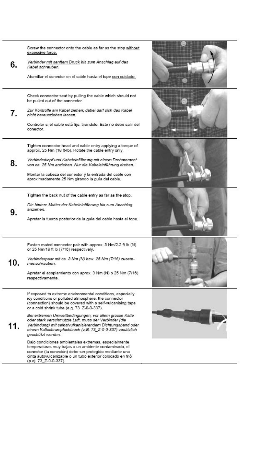
Preliminary
KongsbergAIS300
78A300-02/2.0
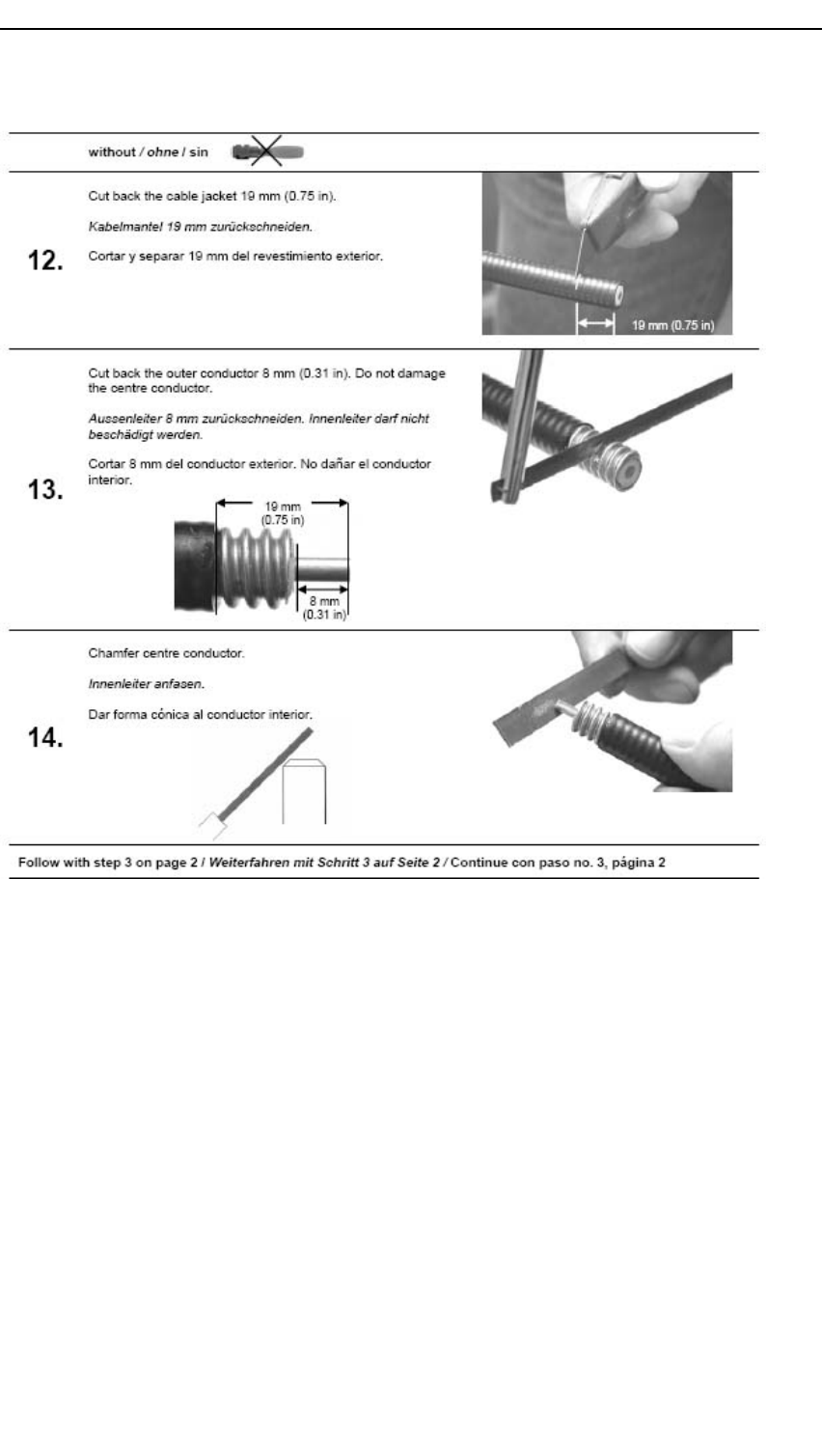
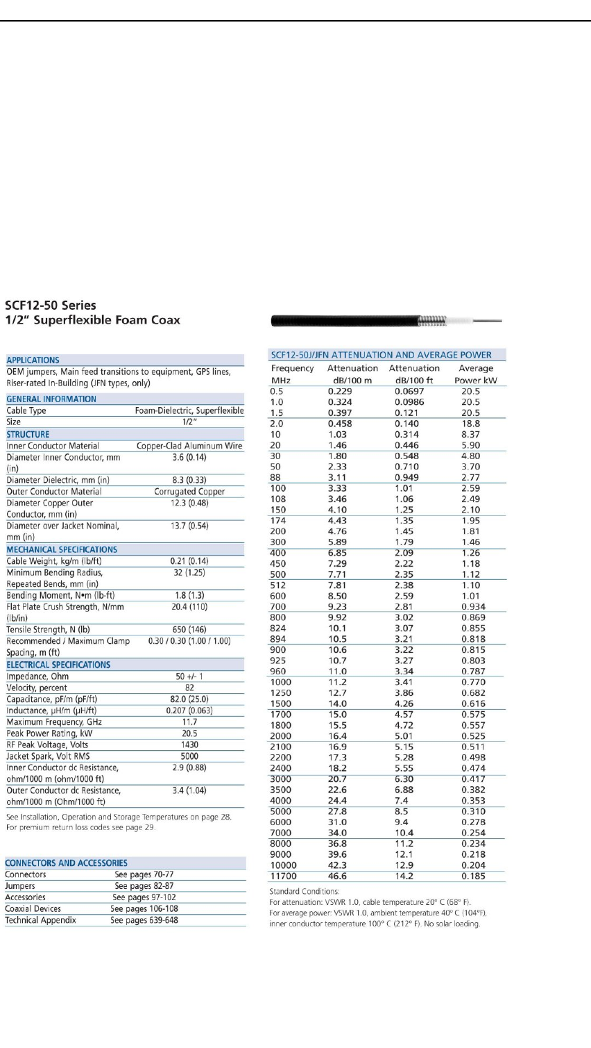
Preliminary
KongsbergAIS300
AppendixD
½"coaxcablespecications
80A300-02/2.0
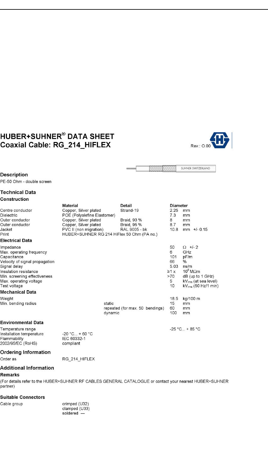
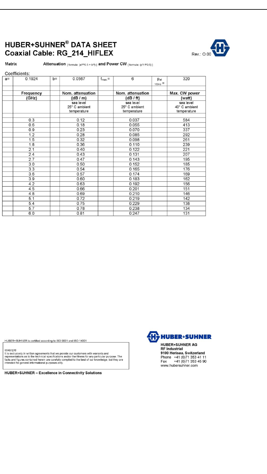
Preliminary
KongsbergAIS300
82A300-02/2.0

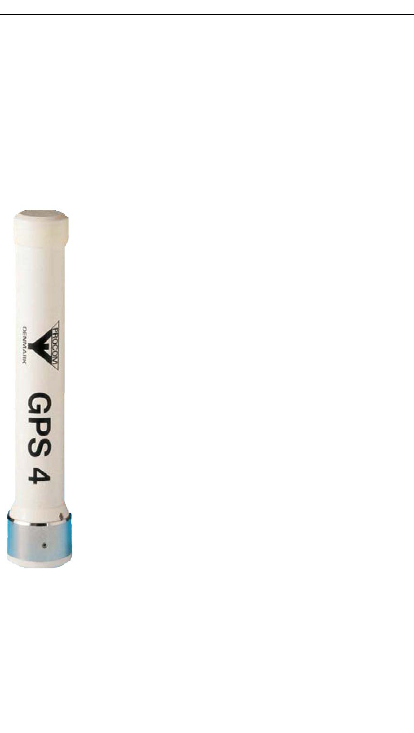
Preliminary
KongsbergAIS300
F .1GNSSantennamechanicaldimensions
andinstallation
ExcerptfromProcomdatasheet
Application
Activereceivingantennaforthe1575MHzNA VSTARGPSSatellitteNavigationSystem
Electricalspecications
ModelandtypeGPS4,quadrilarhelixactive
antenna
Frequency1575MHz
ImpedanceNom.50Ω
PolarisationCircularright-hand
Gain(inaxialdirection)>32dBi
SWR(output)<2.0
Supplyvoltage5±0.5VDC
CurrentconsumptionApprox.44mA
EMCFullprotection(IEC801,IEC255)
Mechanicalspecications
MaterialsAntennadome:weather-resistant
low-lossplastic,
ColourWhite
WindsurfaceApprox.0.0072m2
Max.windspeed200km/h
WindloadApprox.9.6N@150km/h
Temperaturerange-50°Cto+70°C
ConnectorFME-female(pin)(N-femalepigtail
whendeliveredbyKongsberg
SeatexAS)
TotalheightApprox.23cm
Antennadiameter33mm
WeightApprox.150g
Mounting
Verticalon1–inchwaterpipeoronPROCOM1–inchmountingbrackets.
84A300-02/2.0
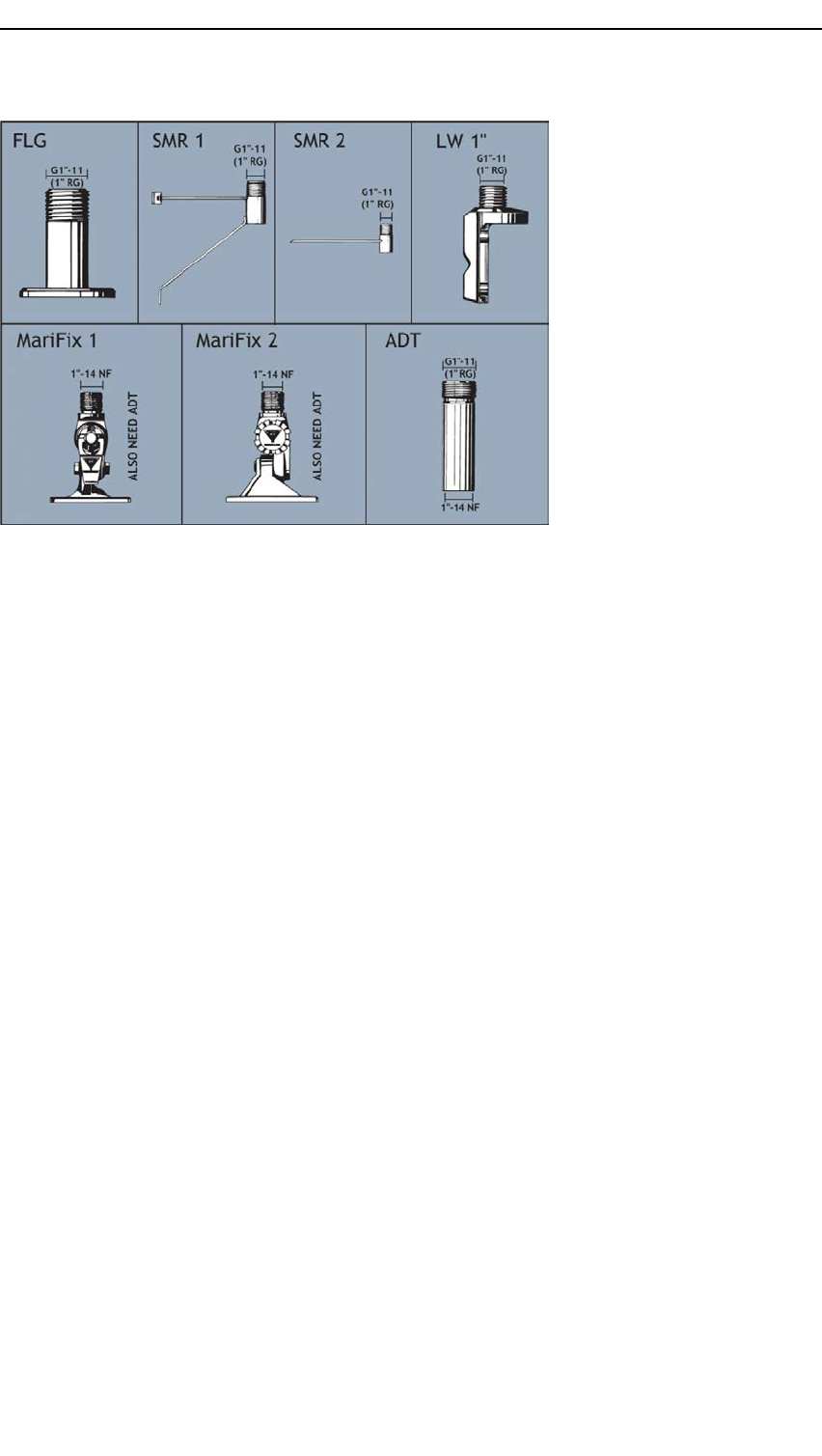
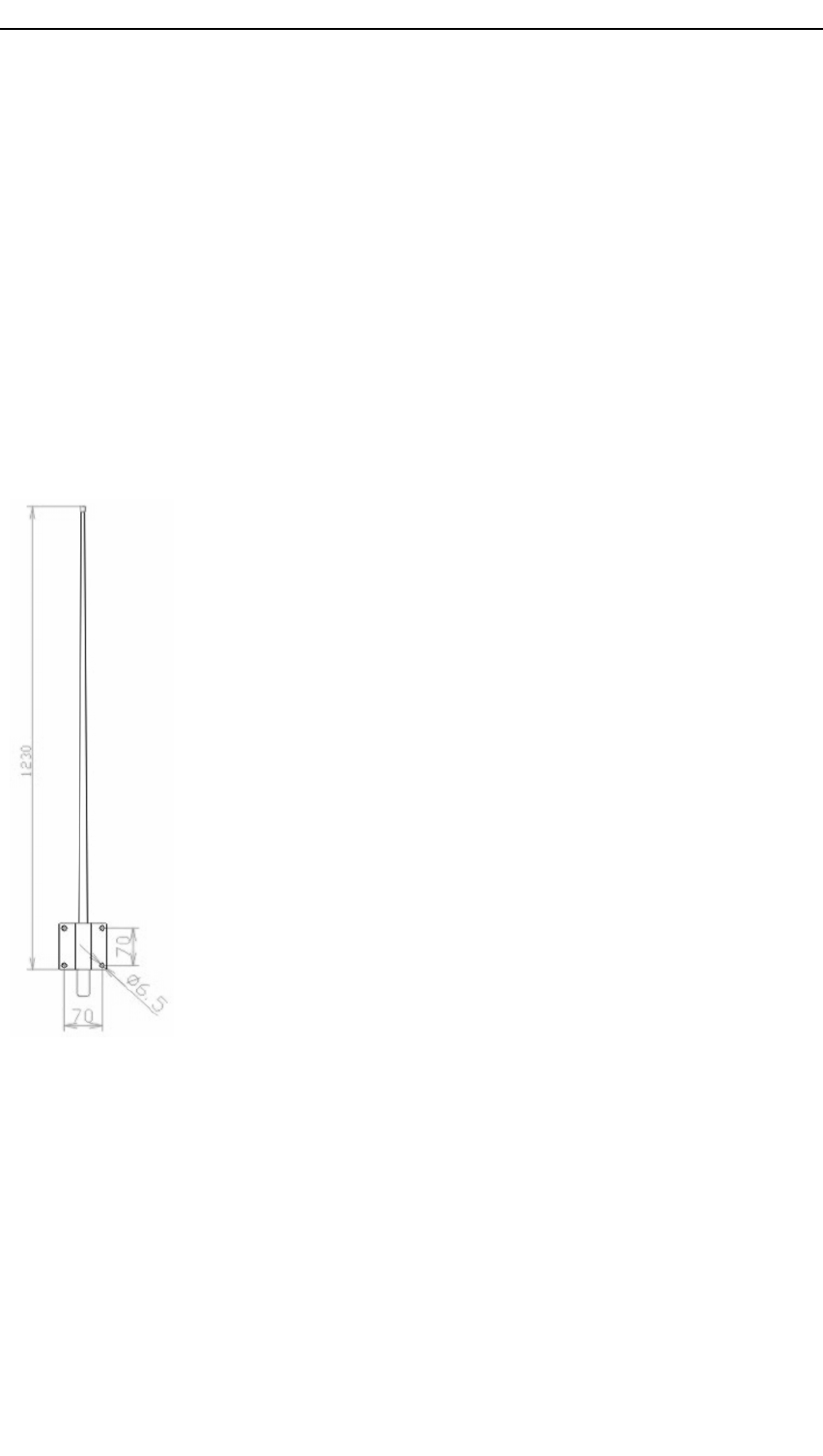
Preliminary
KongsbergAIS300
F .2VHFantennamechanicaldrawingand
installation
ExcerptfromComroddatasheet
Type
ComrodA V7.
Application
HighqualitydipoleantennadesignedforthemarineVHFradiotelephoneservice.
Electricalspecications
Frequencyrange156to162MHz,VSWR<1.5:1
145to165MHz,VSWR<2:1
Nominalimpedance50Ω
Powerrating100W
Gain2dBi
PatternHorizontalplane:Omnidirectional
Verticalplane:seereversepage
PolarisationVertical
ConnectorUHFfemaleisstandard
DC-groundedYes
Mechanicalspecications
DesignCenterfedcoaxialdipole.Radiating
elementscompletelyenclosed
inpolyurethanefoamwithina
berglasstube.Mountingbracketin
aluminium.
Height1.25m(4ft)
Weight1kg,includingU-bolts
Windrating55m/s=125mph
FinishPolyurethanelacquer,white
Temperaturerange-55°C,+71°C(-67°F,+160°F)
Mounting
Mountedtothebulkheadbymeansof4holesinthealuminiumbracketortoamastor
tubewithU-bolts.Thetubemaybehorizontalorvertical.
86A300-02/2.0
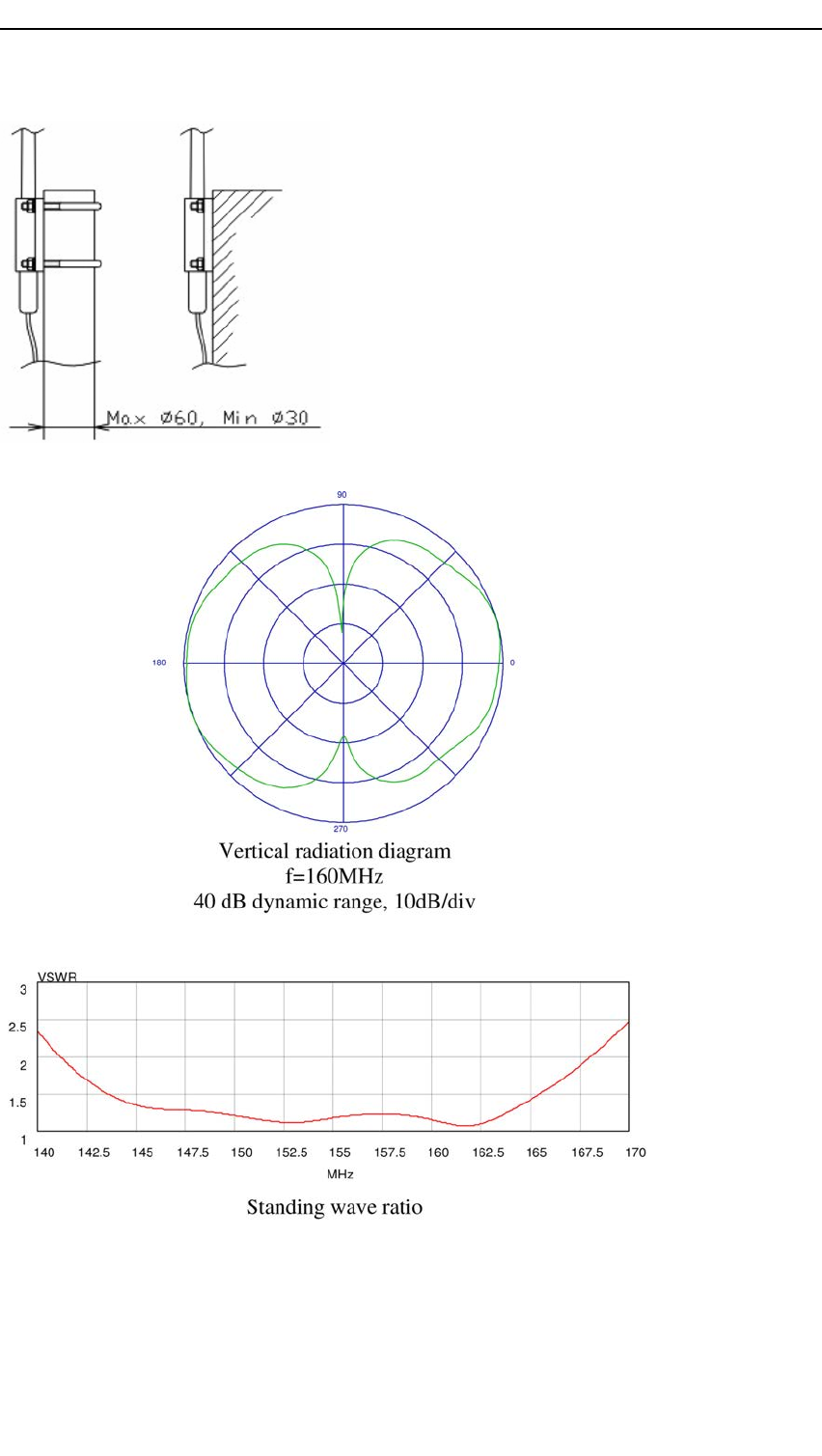
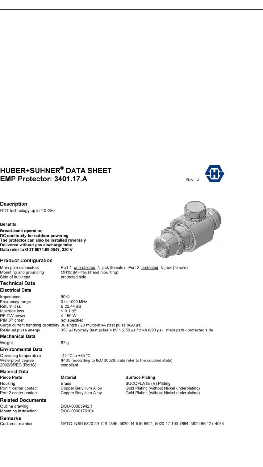
Preliminary
KongsbergAIS300
AppendixG
Lightningarrestor
specications
ExcerptfromHuber+Suhnerdatasheets.
88A300-02/2.0
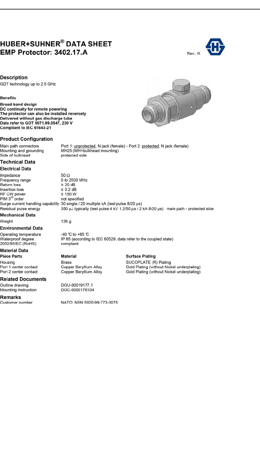
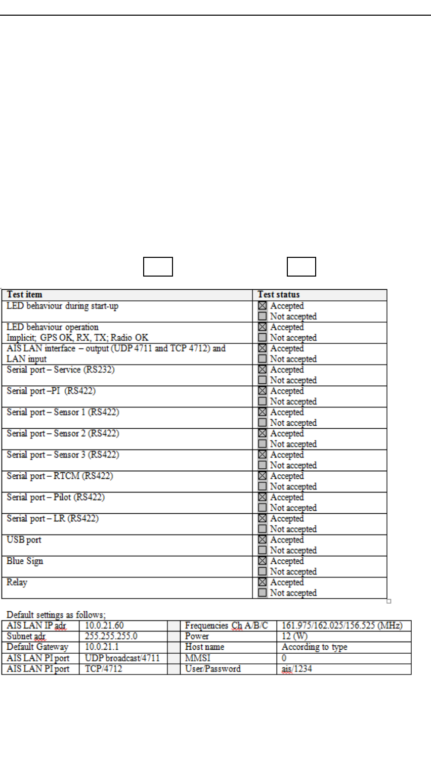
Preliminary
KongsbergAIS300
AppendixH
Productiontest
TheAISUnit,serialnumber:......................................................,hasbeenmountedand
testedaccordingtothevalidrevisionoftheproductdescription.
Type:AIS300AIS300BF
90A300-02/2.0

Preliminary
©2016KongsbergSeatex