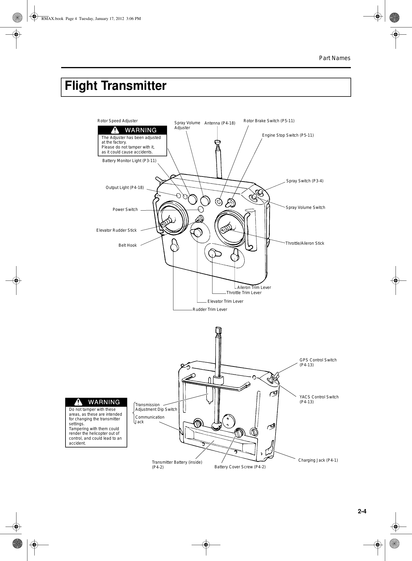
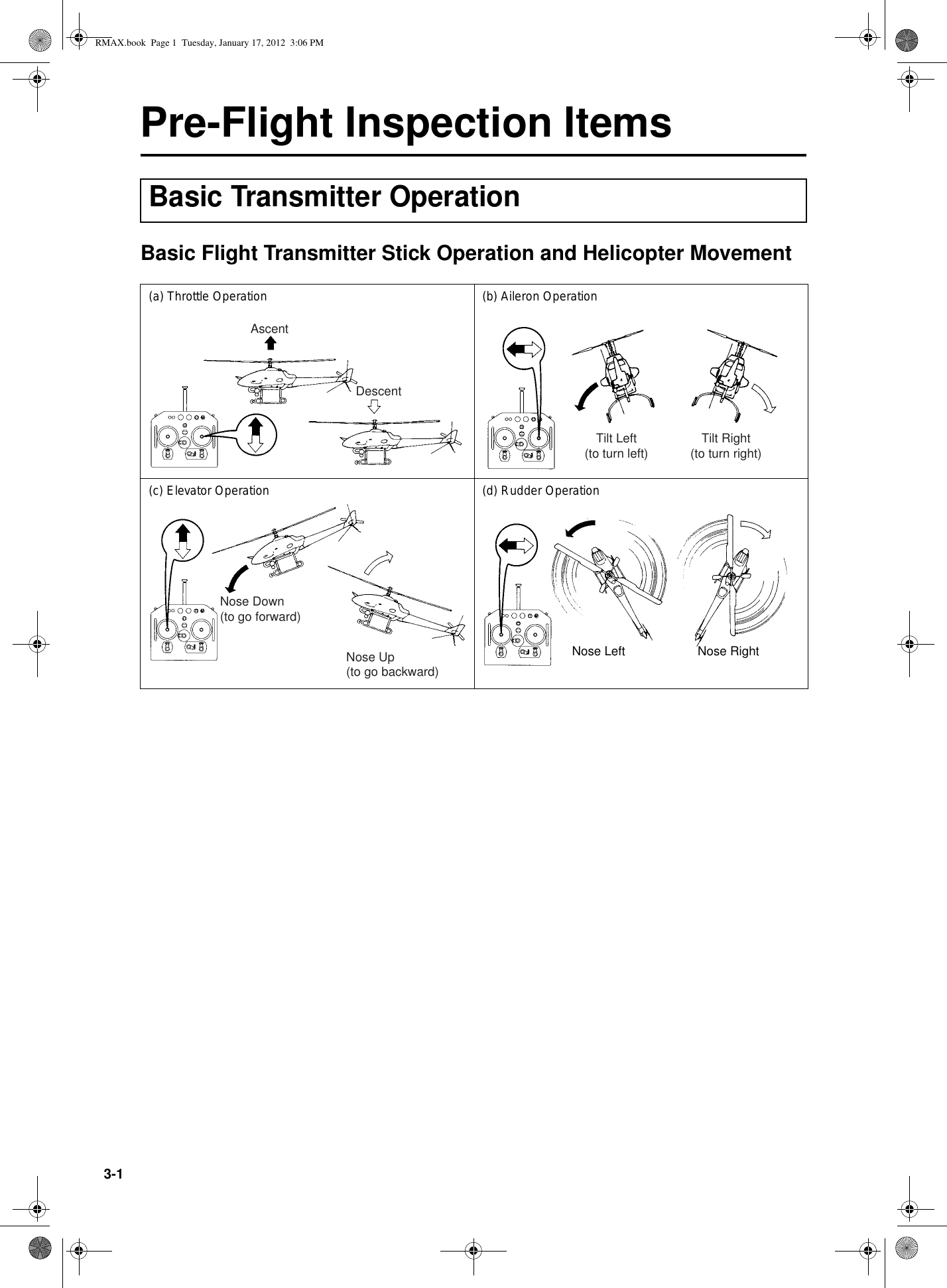
Konishi Mokei L25-N4580 Transmitter for Radio Remote Control User Manual 1

JAPAN REMOTE CONTROL CO., LTD. Transmitter for Radio Remote Control 1

Contents

User manual 1

OPERATION MANUALOPERATION MANUALPlease read this manual before using the product.UNMANNED HELICOPTER FOR INDUSTRIAL APPLICATIONSUNMANNED HELICOPTER FOR INDUSTRIAL APPLICATIONSUNIT, RMAX.book  Page 1  Tuesday, January 17, 2012  3:06 PM
ForewordThank you for using the RMAX TypeII G Unit, unmanned helicopter for industrial applica-tions.This operation manual describes the proper operating procedures and precautions whenusing this product.Before using this product, please be sure to read this operation manual and thoroughlyunderstand its contents.In this manual, the warning notes, which are necessary for safe and proper operation of thisproduct, are categorized and shown as follows. Please make sure to observe these instruc-tions, as they all contain important information.●After you have read this operation manual, keep it within easy access near the helicop-ter.●Contact your dealer if you are lending this helicopter or transferring its ownership.●Keep this operation manual together with the helicopter if you are lending this helicopteror transferring its ownership.●If you have lost this operation manual, contact your dealer to request another copy.●Contact your dealer if you have any questions or comments regarding the contents ofthis operation manual.●Some diagrams and contents in this manual may differ from the actual helicopter, due tospecification changes, etc. ●For information on the sprayer, see the operation manual for the sprayer.This indicates that improper operation willcause imminent danger, which could lead toserious injury or death.This indicates that improper operation couldlead to minor and serious injuries or death.Indicates that improper operation couldcause property damage.Indicates proper operating procedure andtips on inspection and maintenance.Indicates a prohibited action.The specific prohibited action is illus-trated near the symbol.DANGERWARNINGNOTICETIPRMAX.book  Page 1  Tuesday, January 17, 2012  3:06 PM
Table of ContentsSafety PrecautionsDescribes the particulars to be aware of to ensure safe operation. 1Part Names Gives the names of the parts. 2Pre-Flight Inspection ItemsDescribes the items to be checked before operating the product, including the basic operations of the transmitter and the control functions. 3Pre-Flight Preparation and Inspection Describes the proper procedure for transporting, prepar-ing, and inspecting the helicopter prior to flight. 4Flying Procedure Describes the operation procedures, from starting to stop-ping the engine. 5Post-Flight Inspec-tion and CleaningDescribes the proper methods for cleaning and inspecting the helicopter after a flight, in preparation for the next flight. 6Simple MaintenanceDescribes the procedures for simple inspection and main-tenance that can be performed by the user. 7Proper ManagementDescribes the proper methods for storing and maintaining the helicopter. 8Troubleshooting Describes the procedures for identifying the possible causes of a malfunction and the proper actions that must be taken. Use this section as a quick sheet for resolving problems. 9Specifications Gives the specifications and dimensions of the product. 10Product Warranty and Inspection Describes the product warranty and inspection. 11Index Lists the main contents in alphabetical order. Use this section to look up the pertinent page by keyword. 12RMAX.book  Page 1  Tuesday, January 17, 2012  3:06 PM
RMAX.book  Page 2  Tuesday, January 17, 2012  3:06 PM
Safety PrecautionsProduct Safety Label Locations ............................................... 1-1Requirement ............................................................................... 1-2Basic Requirements ...........................................................................1-2Operator Requirements  .....................................................................1-3Helicopter Requirements ...................................................................1-5Flight Requirements ...........................................................................1-7Chemical Requirements ...................................................................1-111RMAX.book  Page 1  Tuesday, January 17, 2012  3:06 PM
1-1Safety PrecautionsBefore operating the helicopter, please read and understand the affixed product safety labels thoroughly.Product Safety Label LocationsRMAX.book  Page 1  Tuesday, January 17, 2012  3:06 PM
Safety Precautions1-2Basic RequirementsRequirementTo ensure safe use, please make sure to readthe operation manual thoroughly before use.WARNINGThis unmanned helicopter for industrialapplications has been manufactured for thepurpose of aerial application of agriculturalchemicals, fertilizers, and seeds. Do not useit for other applications. It could also causeunexpected accidents.WARNINGDo not modify the helicopter or the auxiliarydevices. Do not use parts other than genuineparts. Any modification of the helicopter oruse of non-genuine parts may cause unex-pected accidents.WARNINGRMAX.book  Page 2  Tuesday, January 17, 2012  3:06 PM
Safety Precautions1-3Operator RequirementsObserve the following clothing requirements:• Wear a helmet.• Wear goggles and a particle mask.• Wear long-sleeved clothing with secure buttonsand fasteners.• Wear slip-proof shoes that are easy to walk with.• Do not wear objects that could obstruct visionwhen there is wind, or adversely affect operation(especially towels and gloves).Flying this helicopter requires a high level ofskill.The helicopter should be operated only by aperson who possesses an appropriatelicense.WARNINGCertificate of AuthorizationMake sure to wear a helmet during flight. Toperform an aerial application, make sure towear clothing that is appropriate for the oper-ation. Performing a flight and an aerial appli-cation in clothing that is not appropriate forthe task could cause loss of visibility, maneu-vering error, or cause your foot to slip, result-ing in unexpected accidents. Furthermore, itcould harm your health through exposure toagricultural chemicals.WARNINGA minimum of 3 people is required for anaerial application: a navigator who has beenbriefed on the aerial application procedure,an assistant who readies, mixes, and sup-plies agricultural chemicals, and an operator.Beware that an understaffed operation couldlead to an accident.WARNINGRMAX.book  Page 3  Tuesday, January 17, 2012  3:06 PM
Safety Precautions1-4The operation of an unmanned helicopterinvolves considerable mental fatigue. Theoperator should not fly the helicopter contin-uously for more than 1 hour, but should takea rest every hour. Prolonged continuousflight operation could cause the operator tolose concentration and could lead to an acci-dent.Do not fly the helicopter after drinking alco-hol or taking cold medicine, or if you are inpoor physical condition. Flying the helicopterin poor physical condition could cause lossof concentration, and could lead to an acci-dent.WARNINGWARNINGRMAX.book  Page 4  Tuesday, January 17, 2012  3:06 PM
Safety Precautions1-5Helicopter RequirementsMake sure to perform the following inspections. Inaddition, have your dealer perform the 30-hourinspection, periodic inspection, and general inspec-tion. (See pages P11-1 and P11-2.)•Pre-flight inspection•Post-flight inspection•30-hour inspection•Periodic inspection•General inspectionNever approach (or allow others to approach)within 20 m of the helicopter until the mainrotor has come to a complete stop and theengine has stopped. Entering within 20 m ofthe helicopter could cause a serious acci-dent.DANGER20 m 20 m20 m20 mThe fuel mixture contains highly volatile gas-oline that ignites easily. To prevent fires, stopthe engine and keep the helicopter away fromany source of sparks or fire when refueling ormixing gasoline with oil.WARNING●Make sure to have the required inspec-tions and maintenance services per-formed. Failure to do so could lead to aserious accident.●To have the helicopter serviced, contactyour dealer or an authorized service facil-ity for Yamaha unmanned helicopters forindustrial applications.WARNINGRMAX.book  Page 5  Tuesday, January 17, 2012  3:06 PM
Safety Precautions1-6When necessary, remove the radiator caponly after the engine has cooled down. If theradiator cap is removed before the enginehas cooled down sufficiently, the scaldingliquid could shoot out and cause burns.WARNINGThe muffler is at a high temperature immedi-ately after a flight. To prevent burns, do nottouch it. Also, to prevent burns or fires, donot place any flammable objects near themuffler.WARNINGAlthough the helicopter has a drip-proof con-struction, it is not waterproof. The areas thatcan be washed by direct spraying of waterare the side covers, tail body, leaves, and therunners. Do not spray water on other areas,as this could cause the helicopter or the aux-iliary devices to fail or operate erroneously.NOTICEThe gyro sensor located at the bottom of thetail body is a precision instrument thatsenses the earth’s weak magnetic force.Therefore, do not place any magnetizedobjects near it, as this could cause the sys-tem to operate erroneously.NOTICERMAX.book  Page 6  Tuesday, January 17, 2012  3:06 PM
Safety Precautions1-7Flight RequirementsIf the helicopter cannot be maneuvered andis about to leave the flight region, make surethat the region is uninhabited, check thesafety of its surroundings, and do the follow-ing to land the helicopter.1Move the throttle stick to the slowest position.2Furthermore, hold down the Engine Stopswitch.DANGER21Never fly over no-fly zones.Flying over no-fly zones could lead to seriousaccidents and chemical injuries.Do not fly in the following areas:●Above or in the vicinity of airports, militaryfacilities, heliports, or landing strips. Thedistance of the no-fly zone will vary ateach facility. Verify with the relevant enti-ties.●Above or in the vicinity of heavily traf-ficked roads, expressways, or railroads.WARNINGRMAX.book  Page 7  Tuesday, January 17, 2012  3:06 PM
Safety Precautions1-8●Above or in the vicinity of industrial com-plexes for petroleum, gas, chemicals,explosives, etc., or areas containing tanksor depositories.●Above or in the vicinity of power transmis-sion lines, power plants, or transformerstations.●Above or in the vicinity of homes andother hazardous obstacles.●Above or in the vicinity of swimmingareas, yacht harbors, fishing harbor facili-ties, reservoirs, or dams.●Above or in the vicinity of areas postedwith “no trespassing” or “keep out” signs.●Above or in the vicinity of areas whereflight is prohibited by police or fire depart-ments.RMAX.book  Page 8  Tuesday, January 17, 2012  3:06 PM
Safety Precautions1-9The unmanned helicopter for industrial appli-cations is operated by way of radio signals.To prevent the helicopter from going out ofcontrol due to unexpected radio signal inter-ference, pay careful attention to any radiosignal interference before and during a flight.WARNINGSelect areas that are appropriate for takeoffsand landings, as described below. Failure toselect an appropriate area could lead to anaccident.●Select flat farm roads or vacant lots withminimal foot or vehicle traffic.●Check that there are no obstacles in thevicinity.●Check that there are no objects that couldbe picked up by the wind (such as mowedgrass, plastic tape, plastic bags, etc.).WARNINGAbort the flight or aerial application if poorweather conditions exist as described below.Failure to do so could pose operation diffi-culties, which could lead to an accident. Inaddition, it could adversely affect the applica-tion and the effectiveness of the sprayedchemicals.●Wind velocity in excess of 3 m/s at aheight of 1.5 m above the ground.●Rain, fog, or lightning in the close vicinity.WARNINGKeep the maximum horizontal distancebetween the operator and the helicopterwithin 150 m, and the flight altitude at 3 - 4 m(from the ground or from the crop). If the dis-tance is any greater, it will prevent the opera-tor from monitoring the posture of thehelicopter and adversely affect the signalreception conditions.For safety, further shorten the distance ifthere are any obstacles in the area.Failure to fly the helicopter within the maxi-mum distance limit could lead to an accident.WARNINGwithin 150m3-4mRMAX.book  Page 9  Tuesday, January 17, 2012  3:06 PM
Safety Precautions1-10Adjust the load to leave some margin in thepayload. A takeoff with a full payloadrequires maximum horsepower and carefulflying technique. An excess payload at thispoint could lead to a serious accident. There-fore, hover the helicopter to check that thereis an ample margin in payload before con-tinuing with the flight. (See page 4-10.)WARNINGIf the YACS warning light illuminates, theGPS indicator light shows an abnormal con-dition, the helicopter exhibits irregularbehavior, or an unusual symptom occurs(such as vibration, sound, coolant leakage,or foul odor), immediately land the helicopterin a safe area. Continuing with the flight inthis state could lead to an accident.WARNINGYACS Warning Light GPS IndicatorLightBring the following items with you to the fly-ing site.Failure to do so could adversely affect theflight and lead to an accident.●Radio signal monitor●Fire extinguisher●First-aid kit●Bullhorn●Stopwatch●Tools●Fuel●Helmet (for all personnel)●Spare battery●Transceiver●Flight log●Operation manual●Certificate of Authorization●Particle mask●GogglesWARNINGCertificate of AuthorizationRMAX.book  Page 10  Tuesday, January 17, 2012  3:06 PM
Safety Precautions1-11Chemical RequirementsWhen operating 2 or more helicopters in agiven area, make sure to use separate radio-wave frequencies and maintain a minimumdistance of 200 m between them.If they approach within 200 m of each other,check the frequency of the other helicopter,and if it is a neighboring frequency, wait untilthe other helicopter passes.NOTICEOver 200mWhen using chemicals, make sure to followthe instructions given on their labels. Do notuse chemicals other than those that havebeen registered for aerial application. Failureto do so could expose animals, plants, orpeople to chemicals for which the operatorwill be required to take social responsibility.WARNINGControl and handle chemicals strictly inaccordance with their manuals. Negligentcontrol and improper handling of chemicalscould lead to chemical pollution or healthhazards.WARNINGRMAX.book  Page 11  Tuesday, January 17, 2012  3:06 PM
Part NamesHelicopter Exterior ..................................................................... 2-1Helicopter Exterior Part Names .........................................................2-1Control Panel and Warning Lights ....................................................2-2Helicopter Interior ...................................................................... 2-3Flight Transmitter  ...................................................................... 2-42RMAX.book  Page 1  Tuesday, January 17, 2012  3:06 PM
2-1Part NamesHelicopter Exterior Part NamesHelicopter ExteriorGPS Indicator LightYACS Warning LightStabilizer BladeStarter Lever (P5-5)RadiatorRubber Hooks (7 locations) (P4-16)MufflerLeafMain Rotor Blade (P4-15)GPS Unit Tail BodyAzimuth Sensor Tail Rotor Blade  (P4-22)AntennaStone Guard  (P4-7)Control Panel (P2-2)Decompression Lever (P5-5)GPS Antenna Fuel Tank CapSide Cover (P4-16)Runner (P4-6)Tail CoverRMAX.book  Page 1  Tuesday, January 17, 2012  3:06 PM
Part Names2-2Control Panel and Warning LightsFlight Mode Selector Switch (P4-13)Main Switch (P5-3)Flight Indicator(P3-5)Shutter Pump Cleaning SwitchSpinner Con-stant Rotation Switch Starter Switch(P5-6)Check Point Indicator(P3-5)Malfunction Area Indicator(P3-6)Hour Meter(P4-14)Red OrangeYACS Warning Light(P3-7) GPS Indicator Light(P3-9)Self Monitor(P3-5)Sprayer Selec-tor Switch(P4-3)RMAX.book  Page 2  Tuesday, January 17, 2012  3:06 PM
Part Names2-3Helicopter InteriorCarburetorRadiator CapPlug Cap (left)Battery (P7-1)Air Cleaner Air Inlet (left)Slide ServoFuel Tank (P4-19)Recovery Tank (P4-20)Air Cleaner Air Inlet (right)Plug Cap (right)Slide Servo Thermo SensorRMAX.book  Page 3  Tuesday, January 17, 2012  3:06 PM
Part Names2-4Flight TransmitterOutput Light (P4-18)Battery Monitor Light (P3-11)Spray Volume Adjuster Antenna (P4-18) Rotor Brake Switch (P5-11)Engine Stop Switch (P5-11)Spray Switch (P3-4)Throttle/Aileron StickAileron Trim LeverThrottle Trim LeverElevator Trim LeverRudder Trim LeverPower SwitchElevator Rudder StickBelt HookTransmission Adjustment Dip SwitchGPS Control Switch (P4-13)YACS Control Switch (P4-13)Charging Jack (P4-1)Battery Cover Screw (P4-2)Transmitter Battery (inside) (P4-2)Communication JackSpray Volume SwitchDo not tamper with these areas, as these are intended for changing the transmitter settings.Tampering with them could render the helicopter out of control, and could lead to an accident.WARNINGRotor Speed AdjusterThe Adjuster has been adjusted at the factory.Please do not tamper with it, as it could cause accidents.WARNINGRMAX.book  Page 4  Tuesday, January 17, 2012  3:06 PM
Part Names2-5RMAX.book  Page 5  Tuesday, January 17, 2012  3:06 PM
Pre-Flight Inspection ItemsBasic Transmitter Operation  .................................................... 3-1Basic Flight Transmitter Stick Operation and Helicopter Movement  .........................................................................3-1Basic Flight Transmitter Trim Lever Operation and Helicopter Movement  .........................................................................3-2YACS Control Switch   ........................................................................3-3GPS Control Switch  ...........................................................................3-3Spray Switch .......................................................................................3-4Warnings (Warning Lights and Indicators) and Actions ........ 3-5Self Monitor .........................................................................................3-5Slide servo thermo sensor  ................................................................3-6YACS Warning Light (red)  .................................................................3-7GPS Indicator Light (Orange)  ...........................................................3-9Transmitter Battery Monitor Light  ..................................................3-11Failsafe (Safety Function During Radio Signal Interference) Actions ............................................................... 3-12Safety Features and Actions During Poor GPS Signal Reception ...................................................................... 3-153RMAX.book  Page 1  Tuesday, January 17, 2012  3:06 PM
3-1Pre-Flight Inspection ItemsBasic Flight Transmitter Stick Operation and Helicopter MovementBasic Transmitter Operation(a) Throttle Operation (b) Aileron Operation(c) Elevator Operation (d) Rudder OperationDescentAscentTilt Left(to turn left) Tilt Right(to turn right)Nose Down (to go forward)Nose Up (to go backward)Nose Left Nose RightRMAX.book  Page 1  Tuesday, January 17, 2012  3:06 PM
Pre-Flight Inspection Items3-2Basic Flight Transmitter Trim Lever Operation and Helicopter Move-ment(a) Throttle Trim Lever (b) Aileron Trim Lever(c) Elevator Trim Lever (d) Rudder Trim LeverIncreases idling speedThrottle ValveCarburetorStops drifting to the left Stops drifting to the rightStops drifting forwardStops drifting backwardStops counter-clockwise spin Stops clockwise spin●The throttle trim lever is normally at the lowest position, and the aileron, elevator, and rudder trimlevers are normally at center position.●Fine-tune these positions according to your situation. (See page 5-9.)TIPChap3.fm  Page 2  Wednesday, January 18, 2012  10:17 AM
Pre-Flight Inspection Items3-3YACS Control Switch In the event of a failure in the control system, theYACS control switch enables the operator to switchthe control to manual mode, similar to piloted air-craft. Normally, this is kept “ON”.If the control system fails despite its various built-insafety features, calmly turn this switch OFF andland the helicopter at a safe location in manualmode.When the YACS control switch is OFF, the buzzer inthe transmitter will emit a “beep-beep” sound toinform the operator that control is in manual mode.GPS Control Switch The GPS control switch is used for switchingbetween the following modes: A ⇔ AG, C ⇔ CG, S⇔ SG. (See page 4-13.)Before turning ON the GPS control switch, makesure that the outer lights of the GPS indicator areilluminated. If the GPS indicator lights are OFF orflashing, the GPS control flight mode cannot beused even when the GPS control switch is turnedON.Moreover, in the situations described below, firstturn OFF the switch, then turn it back ON. Other-wise, the GPS control flight mode cannot be used.•GPS control communication has been interruptedbecause the helicopter has landed.•The GPS control switch was ON even beforetakeoff.•GPS control has been interrupted due to poorGPS signal reception.•GPS control has been interrupted because it hasbeen set to manual mode.Turning the YACS control switch OFFswitches to manual mode. Do not confusewith other switches while operating.TIPPushControl OFF (manual) Control ONReleaseYACS Control SwitchControl OFF Control ONOFF ON OFF ONGPS Control SwitchRMAX.book  Page 3  Tuesday, January 17, 2012  3:06 PM
Pre-Flight Inspection Items3-4Spray SwitchThe sprayer can be operated when the powerswitch of the flight transmitter is ON and the mainswitch on the helicopter is in the START or FLIGHTposition.Change the spray switch settings as describedbelow, depending on how you wish to operate thesprayer.Using the Flight Transmitter:Press the (ON/OFF) spray switch on the flighttransmitter ON (pushed in) to operate the sprayer.Press the switch again (released) to stop thesprayer.Pay attention to the surroundings beforepressing the spray switch ON, which will dis-charge chemicals.TIPPushON (to operate) OFF (to stop)ReleaseSpray SwitchPower SwitchRMAX.book  Page 4  Tuesday, January 17, 2012  3:06 PM
Pre-Flight Inspection Items3-5This product features various types of safety func-tions. Thoroughly familiarize yourself with thesefunctions and the meaning of the warnings and indi-cations before a flight, and take appropriateactions.Self MonitorThe self monitor, which is located on the controlpanel, indicates the conditions of the various areasof the helicopter.1 Flight IndicatorIndicates whether the helicopter is able to fly.2 Check Point IndicatorAn indicator will illuminate if a malfunction is discovered on the helicopter while a configuration or a flight isin progress.The malfunction areas indicated here can be handled by the user. Take appropriate actions to respond tothe lights that are lit, and check that the flight indicator 1 shows “”.Warnings (Warning Lights and Indicators) andActions312Item Light Meaning ActionON Able to fly in the YACS-controlled flight mode. OK to flyONSetting YACS control and self-check-ing. Wait until the configuration is com-plete.Control is in manual mode. Turn ON the YACS control switch on the transmitter.ON A malfunction has been discovered through a self-check.Check the indicators 2 and 3 to identify the area of the malfunction and take appropriate actions.Item Light Meaning ActionFlashing Flashes approximately 3 times (10seconds) when the main switch isswitched from OFF to START.Wait until the configuration is complete (light OFF).ON The remaining fuel is below specifica-tion level. Refuel.ON The engine speed has dropped due to a high-load condition caused by exces-sive payload or rough maneuvering, etc.Reduce the payload, or fly the helicop-ter more gently.ON Because no control signals were received, the failsafe control took over.Check whether the power switch of the transmitter is ON. Once this indicator light illuminates, it will continue to illu-minate until the main switch on the helicopter is turned OFF.RMAX.book  Page 5  Tuesday, January 17, 2012  3:06 PM
Pre-Flight Inspection Items3-63 Malfunction Area IndicatorAn indicator will illuminate or flash if a malfunction is discovered on the helicopter while a configuration or aflight is in progress.The malfunction areas indicated here cannot be handled by the user. Contact your dealer to describe thesymbol for the light that has turned ON or is flashing, and request a repair.Once one of these indicator lights illuminates, it will continue to illuminate or flash until the main switch isturned OFF.Slide servo thermo sensorThe slide servo thermo sensor indicates the temperature state of the slide servo motor.It will flash when the temperature rises abnormally, or when a malfunction is detected in the thermo sensor.* It may be difficult to see the LED under direct sun light.If the temperature of the slide servo has risen, the LED will return to the ON state once the temperaturedrops after time has passed. If the thermo sensor has a malfunction, it will continue to flash.Indication State Meaning ActionON Normal stateFlashing (Alternates repeat-edly between ON for 1 second and OFF for 1 second)The slide servo temperature has risen, causing an abnor-mal state. The malfunction areas indicated here cannot be handled by the user.Contact your dealer immediately to notify which LED is flashing (L/B/R), and request a repair.Intermittent flashing (Alternates repeat-edly between 0.1 second of ON and 1.9 second of OFF)The thermo sensor has a malfunction. The malfunc-tion areas indicated here cannot be handled by the user.Contact your dealer immediately to notify which LED is intermit-tently flashing (L/B/R), and request a repair.YACS Warning Light GPS Indicator LightRMAX.book  Page 6  Tuesday, January 17, 2012  3:06 PM
Pre-Flight Inspection Items3-7YACS Warning Light (red)If a malfunction is discovered on the helicopter while the YACS control is being configured or a flight is inprogress, the YACS warning light (red) illuminates or flashes in unison with the self monitor, and provides theoperator a description of the warning.If this light illuminates or flashes during a flight, calmly take the appropriate actions in accordance with thedescription of the warning.Indication Self Monitor Status Meaning ActionAll OFF No malfunction OK to flyAll ON(*1) “” flashing YACS control is being config-ured. Wait until the configuration is complete (approx. 10 sec). During this time, check for blown bulb in the YACS warning light.One of the malfunc-tion area indicators illuminatesControl has been switched to manual mode due to a mal-function.Calmly land the helicopter in a safe area, contact your dealer to report which indicator is lit on the self monitor, and request a repair.No display on self monitor; thermo sensor flashingThe slide servo has heated up abnormally, or the thermo sensor has a malfunction.Calmly land the helicopter in a safe area. If there is no indication on the self monitor, take actions described on page 3-6.Only outer lights flash(for 15 sec after startingengine)After the engine has started, for 15 sec. OK to fly after flashing has stopped and all lights are OFF. (See page 5-8.)Only outer lights flash(3 times) “” illuminat-ingA high load has been applied due to reasons 1 to 3, causing the engine speed to drop or the rudder to move considerably in one direction.1Excessive payload.2Rough maneuvering3Effects from strong wind, etc.1Calmly land the helicopter in a safe area and reduce the pay-load. (See page 4-10.)2Operate the helicopter more gently.3Fly at a wind velocity of 3 m/s or less.Only outer lights flash(Continuous flashing) If the lights flash more than 3 times, the stability in the rudder direction will deteriorate.Turn the OFF YACS control switch and turn it back ON to recover from this condition.Only inner lights flash “” is ON The remaining fuel is below specification level. Calmly land the helicopter in a safe area and refuel. (See page 4-4.)RMAX.book  Page 7  Tuesday, January 17, 2012  3:06 PM
Pre-Flight Inspection Items3-8*1: The “All ON” state will take precedence over other states (i.e., when all lights are ON, no flashing will takeplace to indicate other concurrent states).Inner and outer lights flash alternately(3 times)“” is ON Because no control signals were received, the failsafe control took over.Take appropriate actions in accor-dance with “Failsafe (Safety Func-tion During Radio Signal Interference) Actions”. (See page 3-12.)If the helicopter responds immedi-ately to control, calmly land it in a safe area. Then, check for radio signal interference (P4-9) and conduct a radio signal distance test (P4-25).Only outer lights are ON Flight velocity has exceeded 20km/h. Fly at a velocity of 20km/h or less. (See page 5-10.)Indication Self Monitor Status Meaning ActionRMAX.book  Page 8  Tuesday, January 17, 2012  3:06 PM
Pre-Flight Inspection Items3-9GPS Indicator Light (Orange) The GPS indicator lights (orange) illuminates or flashes to inform the operator of the reception conditions ofthe GPS signals and the state of GPS control.Take the appropriate actions in accordance with the description of the warning.Condition Indication Meaning ActionBefore starting engineAll OFF Preparing GPS control set-tings (awaiting completion of YACS control configuration)Wait until the completion of YACS control configuration (when all YACS warning lights turn OFF).If the outer lights do not flash after the YACS control configuration has completed, there may be an equipment failure.Only outer lights flash GPS control is being config-ured. GPS control is being prepared. Fly the heli-copter by using only YACS control or wait for the GPS control configuration to com-plete (the outer lights illuminate).If the outer lights do not illuminate after 3 minutes, the GPS signal reception might be poor. Therefore, fly the helicopter by using only YACS control.Only outer lights are ON(all lights illuminate with GPS control switch ON)GPS control configuration is complete. The GPS control settings have been com-pleted and the GPS control is for use.Turn the GPS control switch ON and check that all the lights are lit.RMAX.book  Page 9  Tuesday, January 17, 2012  3:06 PM
Pre-Flight Inspection Items3-10After start-ing engine Only outer lights flash GPS signal reception is good but GPS control cannot be used due to reason 1 or 2.1Before takeoff / after land-ing2Control is in manual modeIn case of reason 1, the outer lights will change from flashing to steady ON after takeoff.In case of reason 2, turn ON the YACS control switch on the transmitter.Only outer lights are ON GPS signal reception is good.GPS control is not being used.GPS control is ready for use. To use it, turn ON the GPS control switch on the transmit-ter.All lights ON GPS signal reception is good.GPS control is being used.The flight is under GPS control.Repeated cycle of “outer lights ON > inner lights ON > OFF”.GPS signal reception has worsened and GPS control cannot be used.The flight mode switches automatically to YACS control. Calmly operate the flight.When using the SG mode, the light turns ON and the brake control will be applied automatically according to speed, only in the longitudinal direction of the helicopter. (See page 3-15.)Turn OFF the GPS control switch on the transmitter to stop the flashing of the lights.Only inner lights are ON GPS control without gyro sensor Turn the GPS control switch OFF, and fly under YACS control.All OFF GPS control cannot be used due to poor GPS signal reception.Operate the flight under YACS control until the GPS signal reception improves (and the outer lights illuminate).Condition Indication Meaning ActionRMAX.book  Page 10  Tuesday, January 17, 2012  3:06 PM
Pre-Flight Inspection Items3-11Transmitter Battery Monitor LightIf the voltage of the transmitter battery drops belowa certain level during operation, a warning buzzer(3 beeps) will sound every 2 seconds and the bat-tery monitor light on the transmitter will flash. If youare flying the helicopter at this time, land it immedi-ately and recharge or replace the transmitter bat-tery.The charging status of the battery can be moni-tored by the sound of the buzzer when the power ofthe transmitter is turned ON.In addition, the transmitter also has the following functions to inform the operator of the transmitter status.If the battery monitor light illuminates on thetransmitter, it is a final warning indicatingthat the transmitter battery has beendepleted. Immediately land the helicopterand replace the transmitter battery. Failure todo so could render the helicopter out of con-trol.Beep beep beep beep (4 times) Fully chargedBeep beep beep (3 times)Beep beep (2 times) Requires charg-ing.Beep (1 time) Inoperable unless charged.WARNINGBattery Monitor Light1) Beep-beep once every 2 seconds The control is in manual mode because the YACS control switch is turned OFF. Turn ON the YACS control switch.2) Beep-beep-beep Beep-beep-beep Beep-beep-beep-beep-beep-beep-beep (3-3-7 pattern)Operation may be poor due to a malfunc-tion. Contact your dealer.RMAX.book  Page 11  Tuesday, January 17, 2012  3:06 PM
Pre-Flight Inspection Items3-12If the radio signals for controlling the flight do not reach the helicopter due to interference, the helicopter will berendered out of control, which creates a dangerous situation. In case of radio signal interference, the systemhas a safety feature that alternately flashes the inner and outer lights of the red YACS warning lights and auto-matically effects the flight control described on the following pages. Thoroughly familiarize yourself with thisfeature to take the appropriate actions.Failsafe (Safety Function During Radio SignalInterference) ActionsDuring signal interference, never approachthe helicopter until the main rotor has cometo a complete stop and the engine hasstopped. If there are any people in the area,instruct them to leave the area immediately.DANGER●Do not fly any higher than 3 to 4 m (abovethe ground or crops). When radio signalinterference occurs (i.e. when failsafemode is engaged), the engine speed isautomatically brought to idling state after40 seconds. Flying at a higher altitude willcause the helicopter to descend abruptly.●Make sure to follow the “Actions”instructed in the manual. Failure to do socould cause the helicopter to move unex-pectedly or descend suddenly once itrecovers from the radio signal interfer-ence, and could lead to an accident.●Do not resume flying until you have veri-fied and eliminated the cause of the radiosignal interference. Otherwise, you couldlose control of the helicopter again, lead-ing to an accident. (See pages 4-9 and 4-25.)WARNINGRMAX.book  Page 12  Tuesday, January 17, 2012  3:06 PM
Pre-Flight Inspection Items3-13●Poor GPS Reception (Outer Lights of GPSIndicator Light Are OFF)1In the event of radio signal interference, the innerand outer lights of the red YACS warning lightswill flash alternately and the system will force thehelicopter to descend quickly regardless of theflight mode. If the control radio signals recoverwhile the helicopter is descending, the flightmode will switch automatically to operator con-trol. For this reason, calmly move all the stickson the transmitter to the neutral (center) position,and wait for the signals to recover.2If the helicopter is forced to land because theradio signals have not recovered, the engine isbrought to idle.Depending on the terrain, weather, and flightconditions, the helicopter could overturn. If thehelicopter overturns, never approach the heli-copter, as the engine speed might not decrease.3After a forced landing, turn the throttle to theslowest position and wait for the radio signals torecover or the engine to stop.4If the radio signals do not recover after 1 minutefrom the time the radio signal interferenceoccurred, the engine will stop automatically. Afterthe rotor has come to a complete stop, approachthe helicopter and turn OFF its main switch.Radio signal interference!(Inner and outer YACS warninglights flash alternately.)Descends quicklyRMAX.book  Page 13  Tuesday, January 17, 2012  3:06 PM
Pre-Flight Inspection Items3-14●Good GPS Reception (Outer Lights of GPSIndicator Light Are ON)1When radio signal interference occurs, the innerand outer lights of the red YACS warning lightswill flash alternately, and the system will applythe brake and force the helicopter to hoverregardless of the flight mode. Then, the helicop-ter will automatically start descending slowly. Ifthe control radio signals recover while the heli-copter is descending, the flight mode will switchautomatically to operator control. For this rea-son, calmly move all the sticks on the transmitterto the neutral (center) position, and wait for thesignals to recover.2If the helicopter is forced to land because theradio signals have not recovered, the engine isbrought to idle.Depending on the terrain, weather, and flightconditions, the helicopter could overturn. If thehelicopter overturns, never approach the heli-copter, as the engine speed might not decrease.3After a forced landing, turn the throttle to theslowest position and wait for the radio signals torecover or the engine to stop.4If the radio signals do not recover after 1 minutefrom the time the radio signal interferenceoccurred, the engine will stop automatically.After the rotor has come to a complete stop,approach the helicopter and turn OFF its mainswitch.Descends slowly after hovering Brake controlRadio signal interference!(Inner and outer YACS warning lights flash alternately.)RMAX.book  Page 14  Tuesday, January 17, 2012  3:06 PM
Pre-Flight Inspection Items3-15The GPS control operates by receiving radio sig-nals from 4 or more satellites. It may become inop-erable depending on the surroundings, terrain,weather conditions, time zone, and other reasons.If the reception of GPS signals becomes poor whileoperating in a GPS control flight mode (SG, CG, orAG), a safety feature will cause the outer and innerlights of the orange GPS indicator lights to flashalternately. Then, the system will automaticallyeffect flight control or switch the flight mode asdescribed below. Thoroughly familiarize yourselfwith this feature to take the appropriate actions.●Operating in SG modeAs the GPS signal reception worsens, the orangeGPS indicator lights will cycle through “outer lightsON > inner lights ON > OFF”, and the brake controlwill be applied only in the longitudinal direction of thehelicopter. At this point, quickly turn OFF the GPScontrol switch. Because GPS control cannot be usedeven before the GPS control switch is turned OFF,the helicopter will operate in the slow flight mode.This flight mode is not suitable for aerial application.In addition, GPS control will not resume even if theGPS signal reception improves. When the GPScontrol switch is turned OFF, the GPS indicator lightwill turn OFF and control will switch to S mode.Therefore, operate carefully.●Operating in CG modeAs the GPS signal reception worsens, the orangeGPS indicator lights will cycle through “outer lightsON > inner lights ON > OFF”. Control will switchautomatically to C mode. At this point, quickly turnOFF the GPS control switch and operate carefully.When the GPS control switch is turned OFF, theGPS indicator light will turn OFF.●Operating in AG modeAs the GPS signal reception worsens, the orangeGPS indicator lights will cycle through “outer lightsON > inner lights ON > OFF”. Control will switchautomatically to A mode. At this point, quickly turnOFF the GPS control switch and operate carefully.When the GPS control switch is turned OFF, theGPS indicator light will turn OFF.Safety Features and Actions During Poor GPSSignal Reception If the stick on the transmitter is moved pastthe neutral (center) position to stop the heli-copter when it is flying forward or backwardin SG mode, the automatic brake control willbe applied together with the operator’s brakecontrol if the GPS control is canceled. As aresult, the nose of the helicopter will tilt up toan excessive angle.NOTICEBrake control Poor GPS reception!(Warning pattern on GPSindicator light)RMAX.book  Page 15  Tuesday, January 17, 2012  3:06 PM
Pre-Flight Inspection Items3-16The reception of GPS radio signals can beadversely affected by conditions indicated below ordue to other reasons.1Flying near obstacles such as mountains, trees,or buildings.2The antenna is surrounded by people.3Fewer satellites are available during certain timeslots.RMAX.book  Page 16  Tuesday, January 17, 2012  3:06 PM
Pre-Flight Inspection Items3-17RMAX.book  Page 17  Tuesday, January 17, 2012  3:06 PM
Pre-Flight Preparation and InspectionPreparation Up to the Day Before  ............................................ 4-1Recharging and Replacing Flight Transmitter Battery  ...................4-1Selecting and Setting the Sprayer  ....................................................4-3Preparing Fuel and Refueling ............................................................4-4Preparation on the Day of Flight  .............................................. 4-6Transporting Procedure .....................................................................4-6Radio Signal Interference Inspection  ...............................................4-9Payload Inspection ...........................................................................4-10Selecting the Flight Mode ................................................................4-13Displaying and Recording Flight Hours .........................................4-14Installing and Removing Main Rotor Blades  .................................4-15Installing and Removing Side Covers  ............................................4-16Pre-flight Inspection ................................................................ 4-17Transmitter Inspection .....................................................................4-18Fuel Inspection  .................................................................................4-19Coolant and Oil Inspections ............................................................4-20Rotor Blade Inspection  ....................................................................4-22Servo and Linkage Inspection .........................................................4-23Self Monitor Inspection ....................................................................4-24Radio Signal Distance Test  .............................................................4-25Tail Rotor Drive Belt Inspection ......................................................4-25GPS System Inspection  ...................................................................4-264RMAX.book  Page 1  Tuesday, January 17, 2012  3:06 PM
4-1Pre-Flight Preparation and InspectionRecharging and Replacing Flight Transmitter BatteryRecharging the BatteryMake sure to use the dedicated battery rechargerfor the transmitter, and recharge the battery as fol-lows:1Check that the power switch for the transmitter isturned OFF.2Remove the plug from the charging jack.3Insert the recharger plug into the charging jackon the back of the transmitter.4Insert the power cord for the electrical trans-former (AC 240V → AC 100V) into a power out-let.5Insert the recharger into the electrical trans-former.6The pilot lamp on the recharger illuminates toindicate that the battery is being recharged.The charging temperature range, recharging time,and duration of use of the battery are as follows.7After the battery has been recharged, make sureto install the plug into the charging jack.8The battery monitor function indicates the bat-tery’s charge status and will alert the operatorduring flight if the battery must be replaced. (Seepage P3-11.)Preparation Up to the Day BeforeMake sure to use a fully charged battery forthe flight. Using an insufficiently chargedbattery could render the helicopter out ofcontrol.Charging temperature range: 0-40 °CRecharging time: 14-16 hoursDuration of use: 2.1-3.3 hoursThe dedicated recharger has been designedfor use with AC 100V power outlets.If the recharger is mistakenly connecteddirectly to an AC 240V power outlet, therecharger and the transmitter could be dam-aged. Therefore, use an electrical trans-former (AC 240V → AC 100V) that conformsto Australian standards when recharging thebattery.WARNINGNOTICEPlugRecharger AC100VCharging JackPower SwitchPower OutletElectrical Transformer AC240V→AC100VAC240VRMAX.book  Page 1  Tuesday, January 17, 2012  3:06 PM
Pre-Flight Preparation and Inspection4-2Replacing the BatteryReplace the battery as follows:1Loosen the 2 retaining screws for the batterycover on the back of the transmitter.2Open the battery cover.3Unplug the connector that connects the batterylead wire and the extension lead wire.4Pull out the battery.5Insert the charged battery in such a way that itslead wire is on your left hand side.6Connect the battery lead wire and the extensionlead wire.7Leave some slack in the extension lead wire.8Close the battery cover, being careful not topinch the battery lead wire or the extension leadwire.Storing the BatteryDo not grip the battery unit and pull it out.This could break the battery lead wire.●Orient the connector to match up the col-ors of the wires.●Do not remove the connector between theflight transmitter and the extension leadwire.●After replacing the battery, turn ON thepower of the flight transmitter, and gentlyjiggle the wires (connector) to make surethere is no break in the current.●Batteries are consumables, and their dura-tion of use decreases with each rechargecycle.●The battery and the extension lead wireshould be replaced once a year. To protectthe environment, take the old battery toyour dealer to ensure proper recycling.●If rust forms on any part of the connectors,consult with your dealer, as it could lead topoor connection.WARNINGTIPBattery Lead WireBatteryBattery Cover ScrewsExtension LeadWireConnectorBattery CoverSlack in the extension lead wireEspecially during long-term storage (1 monthor more), be sure to disconnect the batteryconnector. In addition, store the battery in alocation with a temperature of –20 to 30 °C.TIPRMAX.book  Page 2  Tuesday, January 17, 2012  3:06 PM
Pre-Flight Preparation and Inspection4-3Selecting and Setting the Sprayer1Turn the sprayer selector switch to select thesprayer function.•Turn the switch to “” to operate the liquidsprayer.•To use the speed-dependent feature of theliquid sprayer, turn the switch to “”.2Adjust the settings of the sprayer. For details,see the operation manual for the sprayer.●The sprayer selector switch cannot beoperated during a flight.●The speed-dependent feature is enabledonly when the GPS signal reception isgood, regardless of the position of theGPS control switch on the flight transmit-ter.Currently, the granular sprayer is not exported.TIPTIPSprayer Selector SwitchRMAX.book  Page 3  Tuesday, January 17, 2012  3:06 PM
Pre-Flight Preparation and Inspection4-4Preparing Fuel and RefuelingThis product uses a fuel mixture consisting of regu-lar gasoline and a specified type of 2-cycle engineoil (hereafter referred to as “mixing oil”).1Prepare fuel by mixing gasoline with oil. How-ever, do not use gasoline that is blended withethanol.Specified mixing oil:Yamaha-specified oilMixing ratio:Gasoline:mixing oil = 50:1To prevent fire, mix fuel in a well-ventilatedarea, away from any source of sparks or fire.WARNINGMixing OilGasolineMix thoroughly●Observe the correct mixing ratio of gaso-line and oil, and mix them thoroughlybefore use.●Once the fuel is mixed, used it as soon aspossible. If the fuel is left unused for along period, the oil could separate. It isbest to prepare just enough fuel mixture tobe used in 1 day.●To facilitate mixing, pour the oil into a con-tainer before pouring in the gasoline.●Volume of gasoline and oil:TIPGasoline Oil5 100 m10 200 m15 300 m20 400 m25 500 m30 600 mRMAX.book  Page 4  Tuesday, January 17, 2012  3:06 PM
Pre-Flight Preparation and Inspection4-52Remove the fuel tank cap and refuel. Make surethat a filter net is installed in the filler inlet.●Stop the engine, and make sure there areno sources of sparks or fire before refuel-ing.●Do not pour the fuel past the refueling limit(up to the neck of the fuel tank). This isdangerous, as the fuel may drip out duringa flight.●After refueling, securely tighten the fueltank cap.WARNINGFuel Tank CapFuel TankFilter NetFuel Tank CapFuel TankFilter NetFuel Tank NeckRMAX.book  Page 5  Tuesday, January 17, 2012  3:06 PM
Pre-Flight Preparation and Inspection4-6Transporting ProcedureInstalling and Removing Transport Wheels (sold separately)To transport the helicopter by rolling it on theground, transport wheels must be attached to thefront of the runners. The installation (or removal) ofthe wheels is done by 2 persons as follows:1Use your hand to lower the stone guard to raisethe front end.2Install (or remove) the transport wheels in therecess located between the wheel and pipe inthe front of the runner.Preparation on the Day of Flight●To prevent burns, do not touch the muffler,which could be very hot after a flight.●Exercise caution to avoid poking your eyeswith the antenna or the like.●Make sure to remove the chemical tank forthe sprayer. If a liquid sprayer is installed,fold the boom before transporting the heli-copter. See the operation manual of thesprayer for details.●Do not allow the main rotor blade to comein contact with the ground or with anyobjects in the area, as this could lead toequipment damage.●Do not hold the helicopter by the tail body,tail cover, radiator, or antenna, as thiscould lead to equipment damage.●Make sure to turn OFF the main switchbefore moving the helicopter. Otherwise,the shocks from the movement will trans-fer onto the sensors, and could cause thehelicopter to operate erroneously.●To transport the helicopter by rolling it onthe ground, attach the transport wheels(sold separately).WARNINGNOTICEChemical TankBoomTransport WheelRunnerStoneGuardRMAX.book  Page 6  Tuesday, January 17, 2012  3:06 PM
Pre-Flight Preparation and Inspection4-7Moving Forward or BackwardLift the tail by holding the grip handle of the stoneguard to move the helicopter forward (or backward).Lifting and Lowering1Remove the main rotor blades before loading thehelicopter on a truck bed. (See page 4-15.)2Make sure that 2 persons or more lift the helicop-ter, with each person holding the runner asshown.Make sure to hold the grip handle to movethe helicopter forward or backward. Do nothold the tail cover or antenna, as this couldlead to equipment damage.NOTICEGrip HandleStone Guard●Do not hold the helicopter by the exhaustpipe of the muffler or the bar for attachingthe sprayer tank, as this could lead toequipment damage.●Transport carefully so as not to damagethe tail rotor.NOTICERMAX.book  Page 7  Tuesday, January 17, 2012  3:06 PM
Pre-Flight Preparation and Inspection4-8Transporting1Use a truck to transport the helicopter.Use a truck to transport the helicopter.Do not attempt to fly the helicopter to anothersite, as this could lead to an accident.Make sure to remove the main rotor bladesbefore transporting the helicopter.WARNINGNOTICERMAX.book  Page 8  Tuesday, January 17, 2012  3:06 PM
Pre-Flight Preparation and Inspection4-9Radio Signal Interference InspectionBecause this product is operated by wireless radiosignals, the presence of radio signals with the sameor neighboring frequency in the vicinity will causethe signals to cross, which will adversely affect thecontrol of the flight. Before a flight, use the suppliedradio signal monitor to check the radio frequenciesthat are being transmitted in the area. (See theoperation manual of the radio signal monitor for itsoperation procedure.)During monitoring, make sure the power switch forthe flight transmitter is turned OFF.●The unmanned helicopter for industrialapplications is operated by way of radiosignals. To prevent the helicopter fromgoing out of control due to unexpectedradio signal interference, pay carefulattention to any radio signal interferencebefore and during a flight.●Cancel the flight if you detect the same fre-quency that you will be using in the vicin-ity. Otherwise, the radio signal interferencecould render the helicopter out of control,and could lead to serious accidents.●Check for radio signal interference regu-larly, including during breaks betweenflights.●Check for radio signal interference eachtime you move to another area.WARNINGRMAX.book  Page 9  Tuesday, January 17, 2012  3:06 PM
Pre-Flight Preparation and Inspection4-10Payload InspectionThe actual payload of this helicopter varies consid-erably according to its operating conditions(weather, temperature, humidity, terrain, obstacles,etc.) and flying methods, as well as the helicopter’sindividual differences.Use the graph on the following page as a rule ofthumb for adjusting the payload with some marginto ensure a safe aerial application flight.Adjust the load to leave some margin in thepayload.A takeoff with the maximum payload requiresmaximum horsepower and careful flyingtechnique. An excess payload at this pointcould lead to a serious accident. Make sureto observe the following:●Refer to the payload graph and check thepayload that meets your requirements.●Check the payload margin by hovering.●If the low speed warning flashes on theYACS warning light, this means there isnot enough payload margin. Remove thechemical tank on the right side before per-forming the flight.●If the position of the throttle stick immedi-ately after takeoff is clearly high, thismeans that there is not enough payloadmargin. Remove the chemical tank on theright side before performing the flight.●If the engine is cold or when flying for thefirst time after a periodic inspection, as aguide, adjust the payload to about half ofthe capacity.●Contamination of the main rotor blades bypollen, etc., will cause the payload capac-ity to decrease. Clean it during breaks.●If the cushion tape has a peel or a damage,it can cause the payload capacity todecrease. Cancel the flight and request arepair by your dealer. (See page 4-22.)WARNINGNOTICERMAX.book  Page 10  Tuesday, January 17, 2012  3:06 PM
Pre-Flight Preparation and Inspection4-11How to Read the Payload Graph(Example)Reference value for payload in an agricultural field at temperature 35 °C, altitude 0 m: 16 kgTemperature(˚C)AltitudeChemical Load Capacity (kg)Maximum Chemical Load Capacity: 16 kgThis graph is not intended to guarantee thepayload performance of the helicopter. Theactual payload values could differ from thisgraph, depending on the helicopter’s condi-tions, operation conditions, humidity, oxygenconcentration, and other factors.TIPTemperature(˚C)AltitudeChemical Load Capacity (kg)Maximum Chemical Load Capacity: 16kgRMAX.book  Page 11  Tuesday, January 17, 2012  3:06 PM
Pre-Flight Preparation and Inspection4-12(Example)Reference value for payload in an agricultural field at temperature 40 °C, altitude 200 m: Approx. 12 kgTemperature(˚C)AltitudeChemical Load Capacity (kg)Maximum Chemical Load Capacity: 12kgRMAX.book  Page 12  Tuesday, January 17, 2012  3:06 PM
Pre-Flight Preparation and Inspection4-13Selecting the Flight ModeBefore a flight, turn the “flight mode selector switch”to the flight mode that you wish to use.•To use the A or AG mode, turn the switch to“A”.•To use the C or CG mode, turn the switch to“C”.•To use the S or SG mode, turn the switch to“S”.Do not operate the flight mode selectorswitch during a flight.TIPFlight Mode Selector SwitchYACS Control Switch YACS control switch ON + GPS control switch ONFlight Mode Selector Switch“OFF”“ON”S Manual ModeControl support is unavail-able in this mode. Use this in emergencies only.S ModeCompared to the C mode, the S mode provides greater control support to ensure safety of the helicopter.SG ModeMove the stick only as much as you wish to fly, and release it to stop the movement. Thus, this mode allows you to operate with peace of mind.It can be used only for flying forward or backward.C C ModeThis standard flight mode uses the YACS control to balance the helicopter’s sta-bility and flying comfort.CG ModeIn addition to the flying charac-teristics of the C mode, this mode provides hovering stabil-ity through GPS control.AA ModeThis mode has less control support than the C mode, allowing the operator to assume more control.AG ModeIn addition to the flying charac-teristics of the A mode, this mode provides hovering stabil-ity that is lower than the CG mode.OFF ONPush ReleaseRMAX.book  Page 13  Tuesday, January 17, 2012  3:06 PM
Pre-Flight Preparation and Inspection4-14Displaying and Recording Flight HoursThe hour meter on the control panel displays andrecords the engine’s flight hours.1TOTAL: Displaying the total flight hoursPress the TOTAL key to display the helicopter’stotal flight hours, which can serve as guidelinesfor changing oil or performing periodic inspec-tions.2TRIP: Displaying the day’s flight hoursPress the TRIP key to display the logged flighthours since the last time it was reset.3TRIP: Resetting the day’s flight hoursAfter the number of TRIP hours appears on thedisplay, simultaneously press the TOTAL andTRIP keys to reset the number of hours to “0”.Make sure to enter the flight hours in theflight inspection log.TIPLCD DisplayTOTAL Key(total flight hours)TRIP Key(short-term cumula-tive hours)RMAX.book  Page 14  Tuesday, January 17, 2012  3:06 PM
Pre-Flight Preparation and Inspection4-15Installing and Removing Main Rotor BladesHow to Install Main Rotor Blades1Insert the main rotor blades into the main bladeholder.2Use an 8mm hex wrench to tighten the retainingbolts.Check the tightening of the retaining bolts as fol-lows:●Tighten each retaining bolt until it comes to astop. Then, back it out between 45° to 90°.Make sure it is not tightened or loosenedexcessively, which could cause vibrations.●Check that the main rotor blades movesmoothly by moving them slightly in the direc-tion of rotation. They are designed to stop bycoming in contact with rubber stops if they aremoved extensively.How to Remove Main Rotor BladesRemove the main rotor blades in reverse order ofinstallation.●There are two main rotor blades: right andleft. Install them by matching the color ofthe mark of the respective main rotor bladeto the blade holder.●Each main rotor blade has a top and bot-tom. Install it so that its leading edge isoriented in the direction of rotation asshown in the cross section diagram.●Check that the main rotor blades are freeof debris such as pollen or bugs beforeinstalling them.NOTICEHex WrenchRetaining BoltMain Rotor BladeMarkAlign groove to boltMarkCross Section DiagramDirection of rotationBlade HolderDirection of rotation●The main rotor blades are properlyinstalled if their retaining bolts do notwobble when the blades are moved verti-cally, and if they move smoothly in thedirection of rotation when a small force isapplied.●Tighten both rotor blades to approximatelythe same amount of torque.TIP Retaining Bolt Main Rotor BladeNo wobble in this directionRMAX.book  Page 15  Tuesday, January 17, 2012  3:06 PM
Pre-Flight Preparation and Inspection4-16Installing and Removing Side CoversHow to Remove Side Covers1Undo the 7 rubber hooks that are located alongthe top of the helicopter by lifting them towardsthe left.2Open the side covers from side to side.3To completely remove a side cover after it isopen, hold the retaining hooks to pull the sidecover sideways and remove it from the frame.How to Reinstall Side CoversReinstall the side covers in reverse order ofremoval.Rubber hooks●Tilt the sprayer antenna towards the rearbefore opening the right side cover.●Make sure the side cover does not getcaught on the starter lever or the fuel tankcap.TIPDo not hold a side cover during removal, asthis could lead to damage.●Place the right and left side covers andlock them in place by engaging the 7 rub-ber hooks.●After the right side cover is closed, returnthe sprayer antenna to its original posi-tion.NOTICETIPSide Cover (right)Side Cover (left) Retaining HooksRMAX.book  Page 16  Tuesday, January 17, 2012  3:06 PM
Pre-Flight Preparation and Inspection4-17To ensure safe and efficient operation of the heli-copter, make sure the operator performs the pre-flight inspection. In addition, enter the results in theflight inspection log.Pre-flight InspectionTo prevent injury, make sure the engine isstopped before performing an inspection.WARNINGInspection Point Inspection Items FlightPre Post1Transmitter • Battery Level• Operation• Antenna installation2 Fuel • Level• Leakage3 Coolant, oil • Level• Leakage4 Rotor blades • Dirtiness, damage• MovementAir cleaner • Dirtiness5Servo, linkage(rudder, throttle) • Operation• Wobble6 Self monitor • States of lighting7Radio signal distance test • Radio signal reach8 Tail rotor drive belt• Tension• Abnormal noise• Wear, damage• Refuel9 GPS system • States of lightingAntenna • Installation state• RustRMAX.book  Page 17  Tuesday, January 17, 2012  3:06 PM
Pre-Flight Preparation and Inspection4-18Transmitter InspectionInspect the flight transmitter battery level, opera-tion, and antenna conditions.1Battery Level InspectionWith the main switch on the helicopter turnedOFF, turn the power to the transmitter ON to per-form the following inspections:●Check that the output light is ON.●Listen to the buzzer for the number of beepsthat indicates the battery level.●Check that the battery monitor light is not illu-minated.This light operates in unison with the numberof beeps of the buzzer. It flashes when thebattery level is low. Afterwards, it will illumi-nate to warn the operator. This condition indi-cates that the battery level is almost empty,and it should be replaced with a fully chargedbattery.2Transmitter Operation InspectionWhen the power of the transmitter is turned ON,apart from the buzzer sounding to indicate thebattery level, if the buzzer beeps in a 3-3-7 pat-tern or the output light does not illuminate, thetransmitter may be malfunctioning. If this occurs,cancel the flight and request a repair by yourdealer.3Antenna InspectionInspect the antenna to make sure it is not loosein the area where it is mounted to the transmitter.Extend the antenna and inspect it for loosenessor rust.If the antenna is loose in the area where it ismounted, tighten the antenna.If the antenna is loose or rusted, replace theantenna.If the transmitter has a malfunction or thebattery level is low, the transmitter will beunable to send radio signals during a flight.Beep beep beep beep (4 times) Fully chargedBeep beep beep (3 times)Beep beep (2 times) Requires charging.Beep (1 time) Inoperable unless charged.WARNINGBattery Monitor LightOutput LightMounted area of antennaTightenRMAX.book  Page 18  Tuesday, January 17, 2012  3:06 PM
Pre-Flight Preparation and Inspection4-19Fuel InspectionInspect the fuel level and check for any leaks.Before performing this inspection, turn OFF boththe main switch for the helicopter and the powerswitch for the transmitter.1Fuel LevelVisually check the fuel level in the fuel tank. Dur-ing refueling, do not remove the filter net.2Fuel LeakInspect the following areas to make sure thereare no fuel leaks:•Fuel Tank•Fuel Tank Cap•Fuel Filter•Fuel Pump•Fuel LinesIf you discover a fuel leak, immediately cancel theflight and request a repair by your dealer.Fuel TankFuel Tank CapFilterNetFuel PumpFuel Filter●To prevent fires, stop the engine and keepthe helicopter away from any source ofsparks or fire during refueling.●Fuel leakage could lead to a fire.WARNINGFuel FilterFuel PipeRMAX.book  Page 19  Tuesday, January 17, 2012  3:06 PM
Pre-Flight Preparation and Inspection4-20Coolant and Oil InspectionsInspect the coolant level and check for any coolantor oil leakage.Before performing this inspection, turn OFF boththe main switch for the helicopter and the powerswitch for the transmitter.1Recovery TankInspect the tank cap for any coolant leakage.Also, check the coolant level.The standard coolant level is between the FULLand LOW marks indicated on the recovery tank.Coolant PreparationCoolant: Dealer-specified coolantMixing ratio: Dealer-specified ratioRecovery TankCapCoolant is toxic, therefore use caution whenhandling it.●If it enters your eye, flush it thoroughlywith water, and seek medical attention.●If it contacts your skin or clothing,promptly rinse with water and wash withsoap water.●If swallowed, induce vomiting and seekmedical attention.Use tap water, instead of well water or naturalwater that contains sodium.WARNINGNOTICERMAX.book  Page 20  Tuesday, January 17, 2012  3:06 PM
Pre-Flight Preparation and Inspection4-212Water PumpInspect the mating surface of the housing cover,rubber hoses, and rubber hose connections forany coolant leakage.During the initial stage of helicopter operation,the water pump may leak a small amount ofcoolant (10 to 20cc could leak from the drainhole at the bottom of the water pump, onto theabsorbent pad provided on the frame). This nor-mal condition occurs while the internal seal isbeing broken in. It will eventually stop with con-tinued operation of the helicopter.3RadiatorInspect the radiator cap and the rubber hoseconnections for any coolant leakage.4EngineInspect the mating surface of the cylinder bodyand the oil seal for any oil leakage, and the cylin-der head for any coolant leakage.5Transmission and Intermediate TransmissionInspect the mating surface of the transmissioncase and the oil seal for any oil leakage.A slight stain of coolant or oil does not indicate anabnormal condition. However, if the coolant or oil isleaking in a dripping manner, cancel the flight andrequest a repair by your dealer.Radiator CapWater PumpCylinder Head HoseRadiatorWhen necessary, remove the radiator caponly after the engine has cooled down. If theradiator cap is removed immediately after theengine has been stopped, when the coolantis extremely hot, the scalding liquid couldshoot out and cause burns.WARNING●Coolant leakage will adversely affect thecooling performance of the helicopter andcause it to overheat.●Oil leakage will reduce the internal lubrica-tion of the transmission and damage thegears and bearings.NOTICETransmission CaseIntermediate TransmissionRMAX.book  Page 21  Tuesday, January 17, 2012  3:06 PM
Pre-Flight Preparation and Inspection4-22Rotor Blade InspectionInspect the rotor blades for damage, dirtiness, andmovement.Before performing this inspection, turn OFF boththe main switch for the helicopter and the powerswitch for the transmitter.1Main Rotor Blades●Inspect the main rotor blades’ surfaces fordirtiness, fissures, cracks, or chips.●Inspect the cushion tape for peeling or dam-age.●After the main rotor blades have beeninstalled, inspect them to make sure theyrotate smoothly in both directions. (See page4-15.)2Tail Rotor Blades●Inspect the tail rotor blades’ surfaces for dirti-ness, fissures, cracks, or chips.●Inspect the cushion tape for peeling or dam-age.●Inspect the tail rotor blades to make sure theyrotate smoothly in both directions.If a rotor blade’s surface is dirty, use householddetergent on a soft cloth, wring the cloth, and use itto wipe the rotor blade’s surface.If the rotor blade is damaged, cancel the flight andrequest a repair by your dealer.Cushion TapeIf a main or tail rotor blade does not movesmoothly or is damaged, it could generatenoise or vibration.NOTICECushion TapeRMAX.book  Page 22  Tuesday, January 17, 2012  3:06 PM
Pre-Flight Preparation and Inspection4-23Servo and Linkage InspectionInspect the servos and linkages for proper opera-tion.Before performing this inspection, turn the powerswitch for the transmitter to ON and the main switchfor the helicopter to START.1Slide Servo and Linkage InspectionInspect the servos and linkages to make surethey smoothly follow the movements of the throt-tle, elevator, and aileron sticks when the sticksare moved slowly up-and-down and side-to-side.Also, make sure the linkages do not wobble.2Throttle Inspection●Throttle fully open and fully closed•Move the throttle stick to its maximum posi-tion and check that the throttle valve in thecarburetor moves to the fully open position.•Move the throttle stick to the slowest posi-tion and check that the throttle valve in thecarburetor moves to the fully closed posi-tion. Keep the throttle trim lever in the lowestposition.●Throttle cable movement and play•Slowly move the throttle stick up and downand check that the throttle cable movessmoothly without catching.•Check that the throttle cable has a slightplay when the throttle valve is in the fullyclosed position.Slide ServoThrottle Valve Fully Open (maximum throttle)Fully Closed(slowestthrottle)Throttle CableCarburetorRMAX.book  Page 23  Tuesday, January 17, 2012  3:06 PM
Pre-Flight Preparation and Inspection4-243Rudder Servo and Linkage InspectionMove the throttle and the rudder sticks up-and-down and side-to-side and check that the servoand the linkage smoothly follow the movement ofthe sticks. Also, check that the linkage does notwobble.If any of the servos operate abnormally or the link-ages wobble, cancel the flight and request a repairby your dealer.Self Monitor InspectionInspect the illumination of the indicator lights on theself monitor for proper operation.1With the power for the transmitter turned ON,turn the main switch on the helicopter to START,and check that all lights illuminate for 2 seconds.2After the YACS control has completed configura-tion, check the illumination of the indicator lights.•Check that the “” flight indicator light illu-minates.•Check that the check point indicator lights donot illuminate.•Check that the malfunction area indicator lightsdo not illuminate.If there is a problem with the illumination of theflight indicators or check point indicators, take theappropriate actions in accordance with the table onpage 3-5.If a malfunction area indicator light illuminates, can-cel the flight and request a repair by your dealer.●If the servos operate abnormally or thelinkages wobble, they could adverselyaffect the control of the helicopter.●If the throttle operates abnormally, it couldadversely affect engine control, whichcould cause the helicopter to go out ofcontrol.WARNINGTake the appropriate actions in accordancewith the indicator lights. By ignoring thelights and continuing to fly, you will lose con-trol of the helicopter and cause a seriousaccident.WARNINGRMAX.book  Page 24  Tuesday, January 17, 2012  3:06 PM
Pre-Flight Preparation and Inspection4-25Radio Signal Distance TestConduct a radio signal distance test to inspect thatthe system is operating normally.Before performing this inspection, turn the powerswitch for the transmitter to ON and the main switchfor the helicopter to START.1Retract the antenna of the transmitter to itsshortest length.2Have one person operate the transmitter whileanother person checks the helicopter, with anapproximate distance of 50 m between the two.3Operate the transmitter and check that the ser-vos operate accordingly. Make sure the “”light of the check point indicator is not lit.If the reach of the radio signals is less than 50 m,cancel the flight and request your dealer for repair.Tail Rotor Drive Belt InspectionInspect the condition of the tail rotor drive belt andapply lubricant to the belt.Before performing this inspection, turn OFF boththe main switch for the helicopter and the powerswitch for the transmitter.1Inspect for looseness in the tension of the belt.2Check that the belt is free of damage, abnormalwear, and noise during operation.3Apply a sufficient amount of the dealer-specifiedlubricant to the belt.If there is a problem with the belt, cancel the flightand request your dealer for repair.If the reach of the radio signals is too short,radio signal interference could render thehelicopter out of control during flight.WARNING50mIf there is a problem with the tail rotor belt, itcould adversely affect the actuation of the tailrotor, which could cause the helicopter to goout of control.WARNINGTail Rotor Drive BeltRMAX.book  Page 25  Tuesday, January 17, 2012  3:06 PM
Pre-Flight Preparation and Inspection4-26GPS System InspectionInspect to make sure the GPS system is operatingnormally.Before performing this inspection, turn the powerswitch for the transmitter to ON and the main switchfor the helicopter to START.Inspect the illumination of the GPS indicator light byreferring to the table on 3-9 - 3-10.If the light flashes for 3 minutes or more after theYACS control has completed configuration, thismeans the reception of the GPS signals may bepoor. In this case, operate the flight only underYACS control. If the GPS indicator light does nei-ther illuminate nor flash, the GPS system may havefailed. In this case, request your dealer for repair.If the power for the flight transmitter is OFF, the lightwill stop illuminating in 1 minute, but this conditionis normal. Turn the power for the flight transmitterON.GPS Indicator LightYACS Warning LightRMAX.book  Page 26  Tuesday, January 17, 2012  3:06 PM
Pre-Flight Preparation and Inspection4-27RMAX.book  Page 27  Tuesday, January 17, 2012  3:06 PM
Flying ProcedureFlying Precautions ..................................................................... 5-1Engine Starting  .......................................................................... 5-3Pre-start Checks .................................................................................5-3Engine Starting ...................................................................................5-5Takeoff Precautions and Checks  ............................................. 5-8Takeoff Procedure ..............................................................................5-8Post-Takeoff Checks ..........................................................................5-9General Aerial Application Pattern  .................................................5-10Landing and Engine Stopping ................................................ 5-11Landing ..............................................................................................5-11Engine Stopping ...............................................................................5-11Precautions for First Flight After Periodic Inspection  ......... 5-13Fuel ....................................................................................................5-13Onboard Battery  ...............................................................................5-13First Flight Procedure  ......................................................................5-135RMAX.book  Page 1  Tuesday, January 17, 2012  3:06 PM
5-1Flying ProcedureThis section summarizes the precautions for a series of operations from takeoff to landing, as well as for han-dling the helicopter. Some of the contents may overlap the instructions given at the Academy.Preparation - TakeoffTakeoff - HoveringFlying PrecautionsNever approach (or allow others to approach) within 20 m of the helicopter until the main rotor hascome to a complete stop and the engine has stopped. Entering within 20 m of the helicopter couldcause a serious accident.DANGER●Do not take off or land on sloping terrain, as this could cause the helicopter to overturn, oradversely affect its control. As a rule, the helicopter should take off and land on a level surface.Make sure to select an appropriate location before commencing a flight.●Select areas that are appropriate for takeoffs and landings, as described below. Failure to selectan appropriate area could lead to an accident.• Select flat farm roads or vacant lots with minimal foot or vehicle traffic.• Check that there are no obstacles in the vicinity.• Check that there are no objects that could get picked up by the wind (such as mowed grass, plastictape, plastic bags, etc.).WARNING●Do not operate the throttle stick while the outer YACS warning light is flashing. The engine willstop if the throttle stick is moved far up.●Do not operate the rudder excessively right before a takeoff, as this will cause the helicopter tomove abruptly in the direction of the rudder after the takeoff.●During takeoff, do not turn ON the GPS control switch, as this could cause the helicopter to notascend straight up.TIP●Do not operate the sticks abruptly as this could cause the helicopter to lose balance and lead toan accident.●For the first flight of the day, allow the helicopter to hover for 1 or 2 minutes while the enginewarms up, and check that the helicopter operates normally. Failure to do so will prevent theengine from attaining the proper power, which could lead to an accident.WARNINGAfter takeoff, turn the GPS control switch ON while hovering. If this switch was ON during takeoff,turn it OFF while hovering, and turn it back ON.TIPChap5.fm  Page 1  Wednesday, January 18, 2012  10:17 AM
Flying Procedure5-2Hovering - FlyingFlying - Landing●Adjust the load to leave some margin in the payload. A takeoff with the maximum payloadrequires maximum horsepower and careful flying technique. An excess payload at this pointcould lead to a serious accident. Therefore, hover the helicopter to check that there is an amplemargin in payload before continuing with the flight.●Keep the distance between the operator and the helicopter within 150 m, and the flight altitude at3 - 4 m (from the ground or from the crop). If the distance is any greater, it will prevent the opera-tor from monitoring the posture of the helicopter and adversely affect the signal reception condi-tions. For safety, further shorten the distance if there are any obstacles in the area. Failure to flythe helicopter within the maximum distance limit could lead to an accident.WARNING●Do not turn continuously while banking in one direction for more than 10 seconds, as this willcause the helicopter to drift as if the trim has shifted.●Do not turn in the SG mode. Because the operation method for this mode is different from othermodes, the helicopter could make an unexpected movement.TIP●Do not lower the throttle stick to the slowest position during a flight, as this could disrupt theengine speed control and cause the helicopter to descend abruptly.●If the YACS warning light or the GPS indicator light shows an abnormal condition, the helicopterexhibits irregular behavior, or an unusual symptom occurs (such as vibration, sound, coolantleakage, or foul odor), immediately land the helicopter in a safe area. Continuing with the flight inthis state could lead to an accident.●Do not press the Engine Stop switch during a flight, as this will stop the engine and cause thehelicopter to descend abruptly. However, to force the helicopter to land in case of an emergency,press the switch after making sure that it is safe to do so.●Abort the flight or aerial application if poor weather conditions exist as described below. Failureto do so could pose operation difficulties, which could lead to an accident. In addition, it couldadversely affect the application and the effectiveness of the sprayed chemicals.• Wind velocity in excess of 3 m per second at a height of 1.5 m above the ground.• Rain, fog, or lightning in the close vicinity.●Observe the following until the engine has come to a complete stop after landing:• Do not turn OFF the power of the flight transmitter.• Do not take remove or replace the battery in the transmitter.Failure to observe these precautions will trip the failsafe device (speed control turns ON auto-matically), which will cause the engine to accelerate suddenly.WARNINGDuring a takeoff or landing, if the engine speed does not decrease even if the throttle stick is low-ered to the slowest position, calmly turn the YACS control switch OFF. This symptom could occur ifa takeoff operation is aborted or if there are a considerable number of landing shocks when thehelicopter lands.TIPChap5.fm  Page 2  Wednesday, January 18, 2012  10:17 AM
Flying Procedure5-3Pre-start Checks1Check that the flight mode selector switch on thehelicopter is set to the position that you haveselected.•To use the A or AG mode, turn the switch to“A”.•To use the C or CG mode, turn the switch to“C”.•To use the S or SG mode, turn the switch to“S”.See page 4-13 for a detailed description of the flightmodes.2Check that the sprayer selector switch is set tothe position of the sprayer that you will be using.•When using the liquid sprayer, turn the switchto “” or “”.3Extend the antenna of the transmitter and turnthe power switch ON.•Check the battery level (the buzzer shouldbeep a minimum of 3 times).•Check that the YACS control switch is ON andthe GPS control switch is OFF.4Turn the main switch on the helicopter to START.•Check that all the lights on the self monitor illu-minate for 2 seconds.•Check all of the lights of the temperature sen-sor monitoring LED.Engine Starting412Currently, the granular sprayer is notexported.TIPRMAX.book  Page 3  Tuesday, January 17, 2012  3:06 PM
Flying Procedure5-45The SETTING light on the check point indicatorflashes approximately 3 times (for 10 seconds),and the system performs YACS control configu-ration and self checks.Check that all the red YACS warning lights on theback of the helicopter illuminate during configuration.If there are no problems, the “” light of theflight indicator will illuminate, indicating that theYACS control configuration has completed.6After the YACS control configuration has com-pleted and the YACS warning light has turnedOFF, the outer lights of the GPS indicator willflash and the GPS control configuration will start.•The outer GPS indicator lights will flash whileGPS control is being configured.•The outer GPS indicator lights will change fromflashing to constant illumination when the GPScontrol configuration has completed (whichtake about 3 minutes).•After the lights illuminate, turn ON the GPScontrol switch on the transmitter. Then, checkthat all the GPS indicator lights illuminate.•After checking that all lights illuminate, turnOFF the GPS control switch.●Do not move the helicopter while the“” light is flashing.●Configuring the YACS control with the heli-copter tilted could cause errors. Therefore,it is recommended to select a flat area forthis purpose.●If the “” light illuminates on the flightindicator, first turn the main switch OFF;then, turn it to START. If the “” lightilluminates again or if the “” lightcontinues to flash, contact your dealer forrepair.TIP5●Step 5 completes the pre-start checks ifyou will not be using GPS control or if youwill be using it later during the flight.●The length of time it takes to complete theGPS control configuration varies accord-ing to GPS signal reception. If it takes toolong (the lights do not illuminate after 3minutes), you will not be able to use GPScontrol in the AG, CG, or SG mode. Oper-ate the helicopter under YACS control untilthe signal reception improves, which willbe indicated by the illumination of theouter lights.TIPOFF ONOuter lights flashing(configuration in progress)(After approximately 3 minutes)Outer lights illuminating(configuration complete)GPS Control Switch ONAll lights illuminatingRMAX.book  Page 4  Tuesday, January 17, 2012  3:06 PM
Flying Procedure5-5Engine Starting1Pull and tilt the decompression lever on the con-trol panel.2Pull and raise the starter lever on the side coveras needed.3Check that the elevator trim lever, rudder trimlever, and aileron trim lever are in center posi-tion.4Make sure the throttle stick on the transmitter isin its slowest position.Attempting to start the engine without oper-ating the decompression lever could causethe engine not to start or accelerate the wearof the battery and the starter motor.TIP Decompression Lever●Use the starter lever if the engine is cold.●Do not use the starter lever if the engine iswarm, such as restarting after a flight.TIPStarter LeverIf the elevator trim lever, rudder trim lever,and aileron trim lever are not in center posi-tion, the helicopter might not ascend straightup at takeoff.At this time, keep the throttle trim lever set tothe lowest position.WARNINGTIPThrottle Trim LeverAileron Trim LeverElevator Trim LeverRudder Trim Lever Throttle StickRMAX.book  Page 5  Tuesday, January 17, 2012  3:06 PM
Flying Procedure5-65Stand on the left side of the helicopter, and whilesecurely supporting the main rotor, keep thethrottle stick at the slowest position with yourright thumb, and press the starter switch withyour left hand.6After the engine has started, return the decom-pression lever and the starter lever to their origi-nal position.Support the main rotor with your body asshown in the illustration. Otherwise, the rotorcould strike and injure you if the helicopter isimproperly adjusted (such as the idle speedbeing too high or the clutch being engaged).●If the engine does not start within 5 sec-onds after pressing the starter switch, waitabout 10 seconds to allow the battery volt-age to recover. Then, press the starterswitch again.●The safety device will trip and prevent thestarter motor from operating if any of thefollowing conditions have not been met:•Main switch is in the START position.•The power switch of transmitter is ON.•The throttle stick of the transmitter is inthe slowest position.WARNINGTIP●Failure to return the decompression leverto its original position will decrease engineperformance, which could lead to an acci-dent.●Failure to return the starter lever will pre-vent the engine speed from increasing,cause the spark plugs to become fouled,the engine to stop during flight, and leadto an accident.WARNINGRMAX.book  Page 6  Tuesday, January 17, 2012  3:06 PM
Flying Procedure5-77After the engine speed has stabilized, turn themain switch to the FLIGHT position.8While making sure that the throttle stick does notrise, quickly walk away from the helicopter, to aminimum distance of 20 m.●Before turning the main switch to FLIGHT,check again that the throttle stick on thetransmitter is in its slowest position.If the throttle stick is raised, the main rotoror the tail rotor could spin and cause aserious accident.●The safety device will trip when the mainswitch is in the START position, prevent-ing the engine speed from increasingabove a predetermined value. If you hearan abnormal sound from the engine, donot turn the main switch to the FLIGHTposition. Instead, turn it OFF and checkthe areas that are possibly affected.Leaving the engine idling for more than 1minute could stain the spark plug, ordecrease the cooling performance of theengine.DANGERNOTICEMain switchNever turn your gaze away from the helicop-ter when walking away from it.DANGER20m or moreRMAX.book  Page 7  Tuesday, January 17, 2012  3:06 PM
Flying Procedure5-8Takeoff Procedure1Start the takeoff operation after the outer YACSwarning lights have finished flashing, and alllights are OFF.2Gradually raise the throttle stick to enable thecontrol to automatically increase the enginespeed.3Slowly move the throttle stick up to take off.Takeoff Precautions and ChecksDo not operate the sticks abruptly as thiscould cause the helicopter to lose balanceand lead to an accident.●If the throttle stick is moved far up whilethe outer YACS warning lights are flashing,the engine will stop.●Do not operate the rudder excessivelyright before a takeoff, as this will cause thetail to move abruptly in the direction of therudder during a takeoff.●During takeoff, do not turn ON the GPScontrol switch, as this could cause thehelicopter to not ascend straight up.WARNINGTIPThrottle StickRMAX.book  Page 8  Tuesday, January 17, 2012  3:06 PM
Flying Procedure5-9Post-Takeoff ChecksPerform the following checks:1While the helicopter is hovering, make sure thehelicopter behaves normally in response to theoperations of the sticks.2When the sticks are kept still in their neutral posi-tion while the helicopter is hovering, the helicop-ter will drift front-and-back and side-to-side,depending on wind conditions. If the helicopterdrifts constantly in one direction, land it in a safearea to make fine adjustments at the trim lever ofthe transmitter.For the first flight of the day, allow the heli-copter to hover for 1 or 2 minutes while theengine warms up, and check that the helicop-ter operates normally. Failure to do so willprevent the engine from attaining the properpower, which could lead to an accident.After takeoff, turn the GPS control switch ONwhile hovering. If this switch was ON duringtakeoff, turn it OFF while hovering, and turn itback ON.WARNINGTIPRudder Trim LeverElevator Trim Lever Aileron Trim LeverRMAX.book  Page 9  Tuesday, January 17, 2012  3:06 PM
Flying Procedure5-10General Aerial Application PatternWhen operating an unmanned helicopter for the purpose of spraying agricultural chemicals, ensure safe oper-ation, as well as the safety of humans, animals, agricultural products, and the environment during aerial appli-cation.Example: Disease and pest control of a rice paddy•Flight altitude: 3 to 4 m•Flying speed: 10 to 20 km/h•Flying interval: 5 or 7.5 m•Wind velocity: 3 m/s maximumAffirmative!Just passed 10 meters,and 5 metersFlying speed between 10 and 20 km/hFlying height between 3 and 4 metersFlying interval 5 or 7.5 metersWindWhen performing tasks such as refueling,never approach (or allow others to approach)within 20 m of the helicopter until the mainrotor has come to a complete stop and theengine has stopped. Entering within 20 m ofthe helicopter could cause a serious acci-dent.If the GPS signal reception is good, the outerYACS warning lights will illuminate if the fly-ing velocity exceeds 20 km, regardless of thestate of the GPS control switch on the flighttransmitter (Velocity display function).Control the flight velocity so that the outerYACS warning lights do not illuminate.DANGERTIPRMAX.book  Page 10  Tuesday, January 17, 2012  3:06 PM
Flying Procedure5-11LandingAfter hovering the helicopter over the landing point,gradually lower the throttle stick to land it.After landing, turns the GPS control switch OFF.Engine Stopping1After the engine speed has lowered, press downthe Engine Stop switch on the transmitter untilthe engine comes to a complete stop.2Press the Rotor Brake switch.3Before turning OFF the main switch of the heli-copter, check the self monitor’s check point indi-cator and the malfunction area indicator lights forany illumination or flashing.Landing and Engine StoppingNever allow anyone to approach within 20 mof the helicopter.If the engine speed does not lower within 3seconds after landing, turn the YACS controlswitch OFF. This will lower the engine speedto idle.DANGERTIPThrottle StickNever approach (or allow others to approach)within 20 m of the helicopter until the mainrotor has come to a complete stop and theengine has stopped. Entering within 20 m ofthe helicopter could cause a serious acci-dent.●Do not press the Engine Stop switchbefore the engine speed has dropped.●The rotor brake will not apply unless thethrottle stick is placed in the slowest posi-tion.DANGERTIP12RMAX.book  Page 11  Tuesday, January 17, 2012  3:06 PM
Flying Procedure5-124Turn OFF the main switch of the helicopter.5Turn OFF the power switch on the transmitter.Main switchObserve the following until the engine hascome to a complete stop:•Do not turn OFF the power of the flighttransmitter.•Do not take the battery out of the transmit-ter.Failure to observe these precautions will tripthe failsafe device (speed control turns ONautomatically), which will cause the engine toaccelerate suddenly.WARNINGRMAX.book  Page 12  Tuesday, January 17, 2012  3:06 PM
Flying Procedure5-13FuelAfter your dealer performs the complete inspection flight for the periodic inspection, the fuels are drained fromthe fuel tank and the carburetor, to prevent the fuel from becoming old during your storage.When flying for the first time, create a mixed fuel with fresh gasoline purchased at a gasoline station shortlybefore flying (within 1 week), and refuel to maximum capacity.Onboard BatterySince the fuel has been drained, it will take a while before the fuel circulates into the carburetor.If the engine does not start within 5 seconds after pressing the starter switch, wait about 10 seconds to allowthe battery voltage to recover and the starter motor to cool down. Then, press the starter switch again.If the rotation of the starter motor is weak, replace the onboard battery, or have your dealer recharge it with thededicated recharger.First Flight ProcedureIn the periodic inspection, various parts of the helicopter are inspected, and a complete inspection flight is per-formed. However, when flying for the first time after a periodic inspection, at a practice session, for example,fly the helicopter gently as a means for the operator to familiarize himself with the various areas of the helicop-ter as well as its maneuverability.1Fill up the tank with fresh fuel. Keep the chemical and water load to one half of the normal load.2Perform pre-flight inspection.3After the engine starts, take off and hover no higher than 1 m above the ground for 2 minutes or longer.4Next, while hovering 2 to 3 m above the ground, fly gently with flare angle of 10 degrees or less, at a flightvelocity of 10 km/h or less, for 10 minutes or longer. During this time, make sure that there is no vibration inthe helicopter, abnormal sound, or other abnormal behavior in response to the various stick operations.5When landing for tasks such as refueling, always wait until the engine has stopped, and the main rotor hasstopped rotating, then open the side cover to visually check the coolant and oil leakage.6After the flight, perform post-flight inspection, cleaning and servicing tasks.Precautions for First Flight After Periodic InspectionNever use leftover fuel as it could cause the engine to stop or operate poorly.NOTICENever charge with a recharger for car batteries, or connect to a car battery using a jumper cable.The electronics (computers) in the helicopter could malfunction.NOTICERMAX.book  Page 13  Tuesday, January 17, 2012  3:06 PM

Navigation menu