Konishi Mokei L25-N4580 Transmitter for Radio Remote Control User Manual 1
JAPAN REMOTE CONTROL CO., LTD. Transmitter for Radio Remote Control 1
Contents
- 1. User manual 1
- 2. User manual 2
User manual 1

OPERATION MANUAL
OPERATION MANUAL
Please read this manual before using the product.
UNMANNED HELICOPTER FOR INDUSTRIAL APPLICATIONS
UNMANNED HELICOPTER FOR INDUSTRIAL APPLICATIONS
UNIT,
RMAX.book Page 1 Tuesday, January 17, 2012 3:06 PM
Foreword
Thank you for using the RMAX TypeII G Unit, unmanned helicopter for industrial applica-
tions.
This operation manual describes the proper operating procedures and precautions when
using this product.
Before using this product, please be sure to read this operation manual and thoroughly
understand its contents.
In this manual, the warning notes, which are necessary for safe and proper operation of this
product, are categorized and shown as follows. Please make sure to observe these instruc-
tions, as they all contain important information.
●After you have read this operation manual, keep it within easy access near the helicop-
ter.
●Contact your dealer if you are lending this helicopter or transferring its ownership.
●Keep this operation manual together with the helicopter if you are lending this helicopter
or transferring its ownership.
●If you have lost this operation manual, contact your dealer to request another copy.
●Contact your dealer if you have any questions or comments regarding the contents of
this operation manual.
●Some diagrams and contents in this manual may differ from the actual helicopter, due to
specification changes, etc.
●For information on the sprayer, see the operation manual for the sprayer.
This indicates that improper operation will
cause imminent danger, which could lead to
serious injury or death.
This indicates that improper operation could
lead to minor and serious injuries or death.
Indicates that improper operation could
cause property damage.
Indicates proper operating procedure and
tips on inspection and maintenance.
Indicates a prohibited action.
The specific prohibited action is illus-
trated near the symbol.
DANGER
WARNING
NOTICE
TIP
RMAX.book Page 1 Tuesday, January 17, 2012 3:06 PM

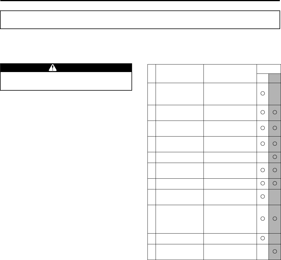
Table of Contents
Safety Precautions
Describes the particulars to be aware of to ensure safe
operation. 1
Part Names Gives the names of the parts. 2
Pre-Flight Inspection
Items
Describes the items to be checked before operating the
product, including the basic operations of the transmitter
and the control functions. 3
Pre-Flight Preparation
and Inspection Describes the proper procedure for transporting, prepar-
ing, and inspecting the helicopter prior to flight. 4
Flying Procedure Describes the operation procedures, from starting to stop-
ping the engine. 5
Post-Flight Inspec-
tion and Cleaning
Describes the proper methods for cleaning and inspecting
the helicopter after a flight, in preparation for the next
flight. 6
Simple Maintenance
Describes the procedures for simple inspection and main-
tenance that can be performed by the user. 7
Proper Management
Describes the proper methods for storing and maintaining
the helicopter. 8
Troubleshooting Describes the procedures for identifying the possible causes of
a malfunction and the proper actions that must be taken.
Use this section as a quick sheet for resolving problems. 9
Specifications Gives the specifications and dimensions of the product. 10
Product Warranty
and Inspection Describes the product warranty and inspection. 11
Index Lists the main contents in alphabetical order.
Use this section to look up the pertinent page by keyword. 12
RMAX.book Page 1 Tuesday, January 17, 2012 3:06 PM
RMAX.book Page 2 Tuesday, January 17, 2012 3:06 PM

Safety Precautions
Product Safety Label Locations ............................................... 1-1
Requirement ............................................................................... 1-2
Basic Requirements ...........................................................................1-2
Operator Requirements .....................................................................1-3
Helicopter Requirements ...................................................................1-5
Flight Requirements ...........................................................................1-7
Chemical Requirements ...................................................................1-11
1
RMAX.book Page 1 Tuesday, January 17, 2012 3:06 PM
1-1
Safety Precautions
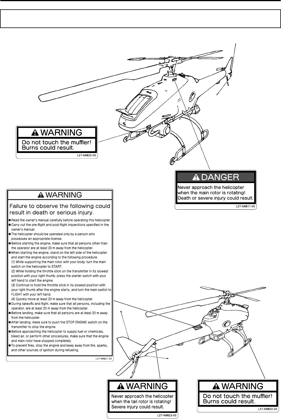
Before operating the helicopter, please read and understand the affixed product safety labels thoroughly.
Product Safety Label Locations
RMAX.book Page 1 Tuesday, January 17, 2012 3:06 PM
Safety Precautions
1-2
Basic Requirements
Requirement
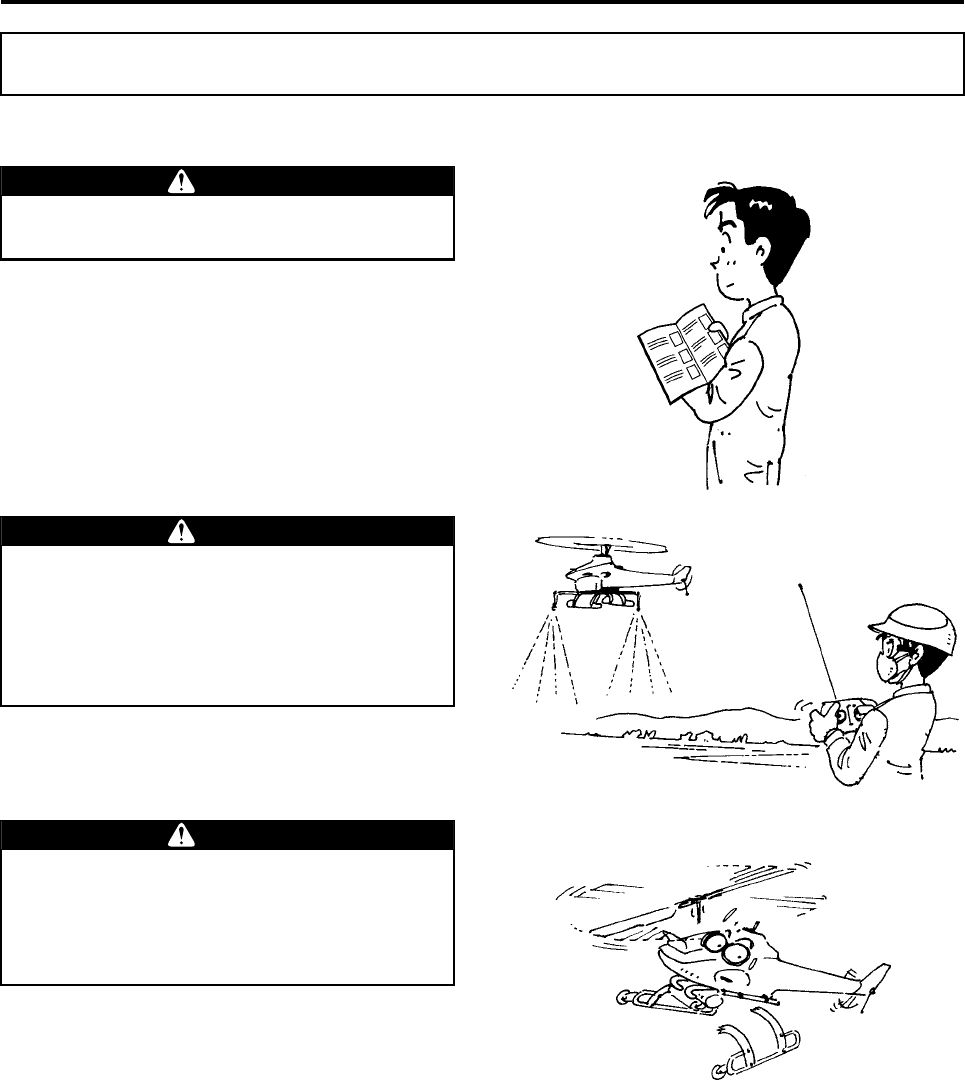
To ensure safe use, please make sure to read
the operation manual thoroughly before use.
WARNING
This unmanned helicopter for industrial
applications has been manufactured for the
purpose of aerial application of agricultural
chemicals, fertilizers, and seeds. Do not use
it for other applications. It could also cause
unexpected accidents.
WARNING
Do not modify the helicopter or the auxiliary
devices. Do not use parts other than genuine
parts. Any modification of the helicopter or
use of non-genuine parts may cause unex-
pected accidents.
WARNING
RMAX.book Page 2 Tuesday, January 17, 2012 3:06 PM
Safety Precautions
1-3
Operator Requirements
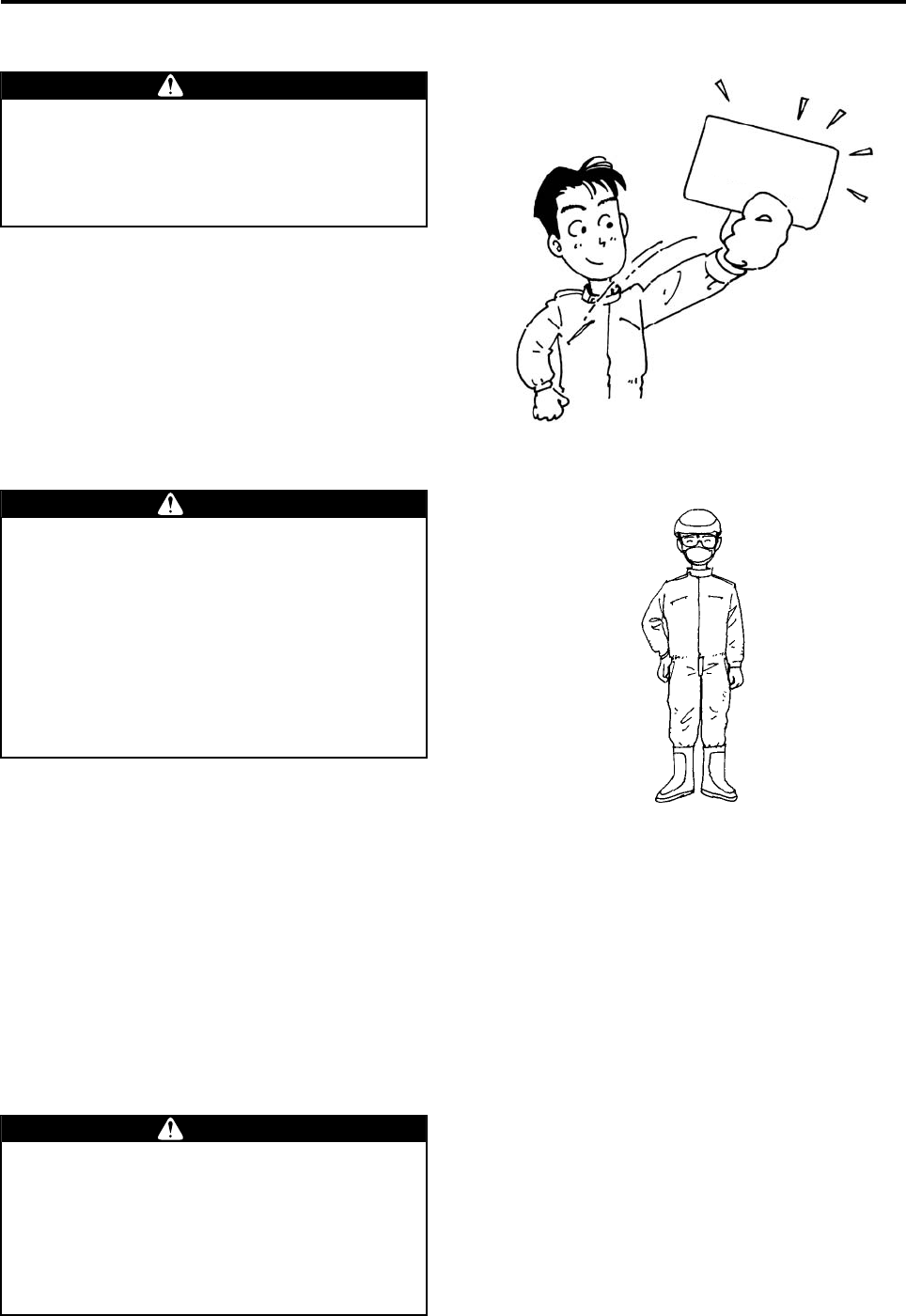
Observe the following clothing requirements:
• Wear a helmet.
• Wear goggles and a particle mask.
• Wear long-sleeved clothing with secure buttons
and fasteners.
• Wear slip-proof shoes that are easy to walk with.
• Do not wear objects that could obstruct vision
when there is wind, or adversely affect operation
(especially towels and gloves).
Flying this helicopter requires a high level of
skill.
The helicopter should be operated only by a
person who possesses an appropriate
license.
WARNING
Certificate of
Authorization
Make sure to wear a helmet during flight. To
perform an aerial application, make sure to
wear clothing that is appropriate for the oper-
ation. Performing a flight and an aerial appli-
cation in clothing that is not appropriate for
the task could cause loss of visibility, maneu-
vering error, or cause your foot to slip, result-
ing in unexpected accidents. Furthermore, it
could harm your health through exposure to
agricultural chemicals.
WARNING
A minimum of 3 people is required for an
aerial application: a navigator who has been
briefed on the aerial application procedure,
an assistant who readies, mixes, and sup-
plies agricultural chemicals, and an operator.
Beware that an understaffed operation could
lead to an accident.
WARNING
RMAX.book Page 3 Tuesday, January 17, 2012 3:06 PM
Safety Precautions
1-4
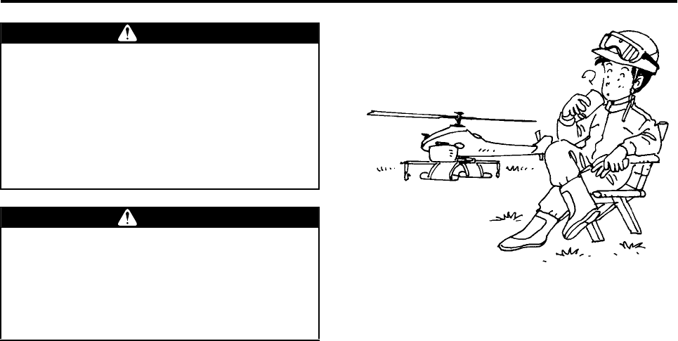
The operation of an unmanned helicopter
involves considerable mental fatigue. The
operator should not fly the helicopter contin-
uously for more than 1 hour, but should take
a rest every hour. Prolonged continuous
flight operation could cause the operator to
lose concentration and could lead to an acci-
dent.
Do not fly the helicopter after drinking alco-
hol or taking cold medicine, or if you are in
poor physical condition. Flying the helicopter
in poor physical condition could cause loss
of concentration, and could lead to an acci-
dent.
WARNING
WARNING
RMAX.book Page 4 Tuesday, January 17, 2012 3:06 PM
Safety Precautions
1-5
Helicopter Requirements
Make sure to perform the following inspections. In
addition, have your dealer perform the 30-hour
inspection, periodic inspection, and general inspec-
tion. (See pages P11-1 and P11-2.)
•Pre-flight inspection
•Post-flight inspection
•30-hour inspection
•Periodic inspection
•General inspection
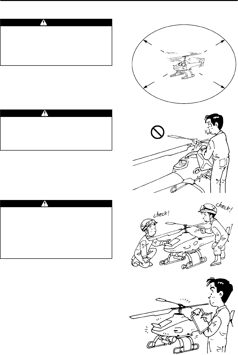
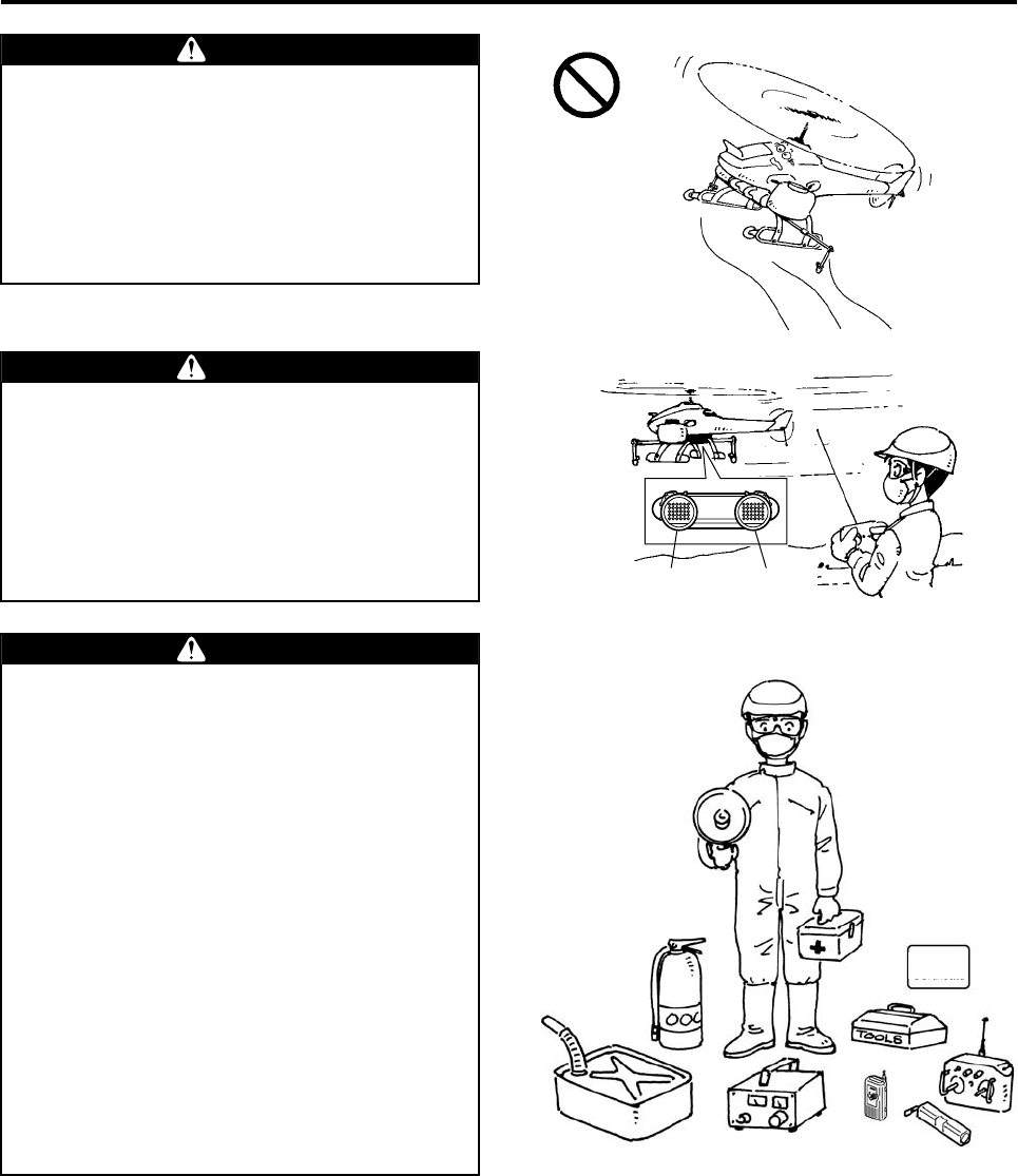
Never approach (or allow others to approach)
within 20 m of the helicopter until the main
rotor has come to a complete stop and the
engine has stopped. Entering within 20 m of
the helicopter could cause a serious acci-
dent.
DANGER
20 m 20 m
20 m20 m
The fuel mixture contains highly volatile gas-
oline that ignites easily. To prevent fires, stop
the engine and keep the helicopter away from
any source of sparks or fire when refueling or
mixing gasoline with oil.
WARNING
●Make sure to have the required inspec-
tions and maintenance services per-
formed. Failure to do so could lead to a
serious accident.
●To have the helicopter serviced, contact
your dealer or an authorized service facil-
ity for Yamaha unmanned helicopters for
industrial applications.
WARNING
RMAX.book Page 5 Tuesday, January 17, 2012 3:06 PM
Safety Precautions
1-6
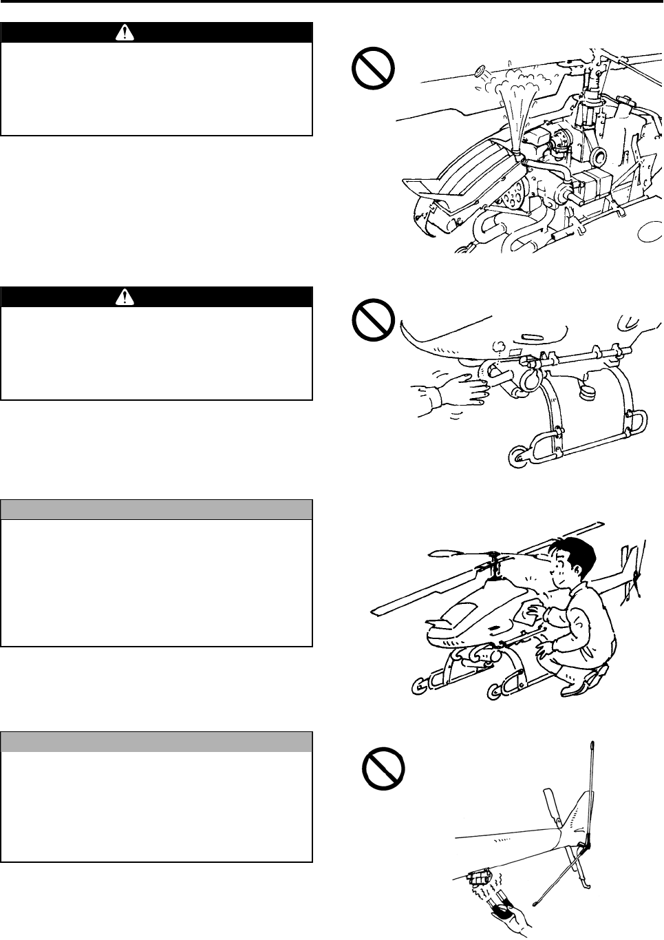
When necessary, remove the radiator cap
only after the engine has cooled down. If the
radiator cap is removed before the engine
has cooled down sufficiently, the scalding
liquid could shoot out and cause burns.
WARNING
The muffler is at a high temperature immedi-
ately after a flight. To prevent burns, do not
touch it. Also, to prevent burns or fires, do
not place any flammable objects near the
muffler.
WARNING
Although the helicopter has a drip-proof con-
struction, it is not waterproof. The areas that
can be washed by direct spraying of water
are the side covers, tail body, leaves, and the
runners. Do not spray water on other areas,
as this could cause the helicopter or the aux-
iliary devices to fail or operate erroneously.
NOTICE
The gyro sensor located at the bottom of the
tail body is a precision instrument that
senses the earth’s weak magnetic force.
Therefore, do not place any magnetized
objects near it, as this could cause the sys-
tem to operate erroneously.
NOTICE
RMAX.book Page 6 Tuesday, January 17, 2012 3:06 PM
Safety Precautions
1-7
Flight Requirements
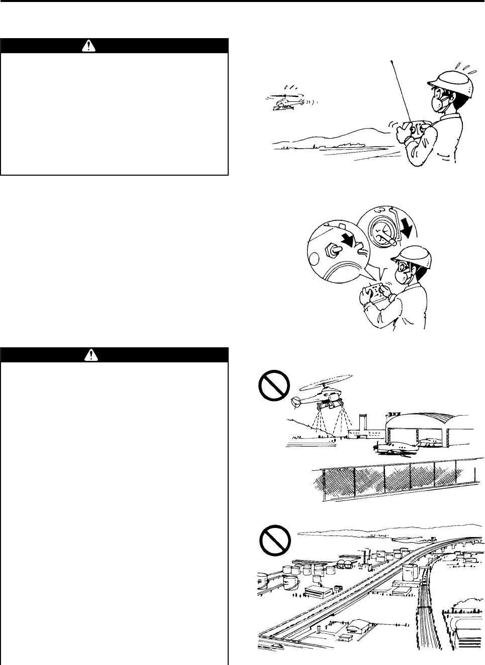
If the helicopter cannot be maneuvered and
is about to leave the flight region, make sure
that the region is uninhabited, check the
safety of its surroundings, and do the follow-
ing to land the helicopter.
1Move the throttle stick to the slowest position.
2Furthermore, hold down the Engine Stop
switch.
DANGER
2
1
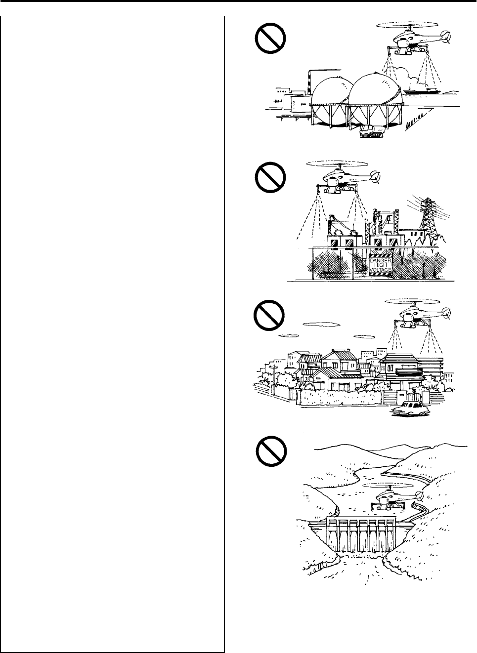
Never fly over no-fly zones.
Flying over no-fly zones could lead to serious
accidents and chemical injuries.
Do not fly in the following areas:
●Above or in the vicinity of airports, military
facilities, heliports, or landing strips. The
distance of the no-fly zone will vary at
each facility. Verify with the relevant enti-
ties.
●Above or in the vicinity of heavily traf-
ficked roads, expressways, or railroads.
WARNING
RMAX.book Page 7 Tuesday, January 17, 2012 3:06 PM
Safety Precautions
1-8
●Above or in the vicinity of industrial com-
plexes for petroleum, gas, chemicals,
explosives, etc., or areas containing tanks
or depositories.
●Above or in the vicinity of power transmis-
sion lines, power plants, or transformer
stations.
●Above or in the vicinity of homes and
other hazardous obstacles.
●Above or in the vicinity of swimming
areas, yacht harbors, fishing harbor facili-
ties, reservoirs, or dams.
●Above or in the vicinity of areas posted
with “no trespassing” or “keep out” signs.
●Above or in the vicinity of areas where
flight is prohibited by police or fire depart-
ments.
RMAX.book Page 8 Tuesday, January 17, 2012 3:06 PM
Safety Precautions
1-9
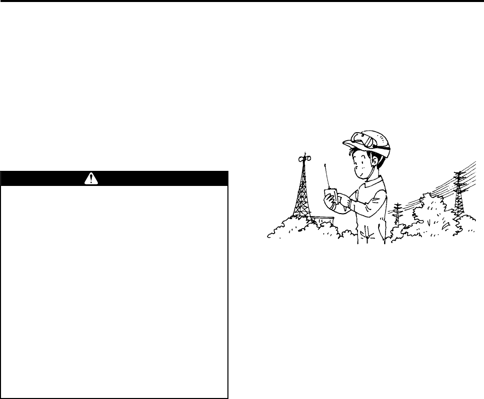
The unmanned helicopter for industrial appli-
cations is operated by way of radio signals.
To prevent the helicopter from going out of
control due to unexpected radio signal inter-
ference, pay careful attention to any radio
signal interference before and during a flight.
WARNING
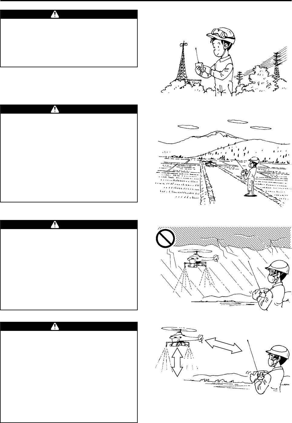
Select areas that are appropriate for takeoffs
and landings, as described below. Failure to
select an appropriate area could lead to an
accident.
●Select flat farm roads or vacant lots with
minimal foot or vehicle traffic.
●Check that there are no obstacles in the
vicinity.
●Check that there are no objects that could
be picked up by the wind (such as mowed
grass, plastic tape, plastic bags, etc.).
WARNING
Abort the flight or aerial application if poor
weather conditions exist as described below.
Failure to do so could pose operation diffi-
culties, which could lead to an accident. In
addition, it could adversely affect the applica-
tion and the effectiveness of the sprayed
chemicals.
●Wind velocity in excess of 3 m/s at a
height of 1.5 m above the ground.
●Rain, fog, or lightning in the close vicinity.
WARNING
Keep the maximum horizontal distance
between the operator and the helicopter
within 150 m, and the flight altitude at 3 - 4 m
(from the ground or from the crop). If the dis-
tance is any greater, it will prevent the opera-
tor from monitoring the posture of the
helicopter and adversely affect the signal
reception conditions.
For safety, further shorten the distance if
there are any obstacles in the area.
Failure to fly the helicopter within the maxi-
mum distance limit could lead to an accident.
WARNING
within 150m
3-4m
RMAX.book Page 9 Tuesday, January 17, 2012 3:06 PM
Safety Precautions
1-10
Adjust the load to leave some margin in the
payload. A takeoff with a full payload
requires maximum horsepower and careful
flying technique. An excess payload at this
point could lead to a serious accident. There-
fore, hover the helicopter to check that there
is an ample margin in payload before con-
tinuing with the flight. (See page 4-10.)
WARNING
If the YACS warning light illuminates, the
GPS indicator light shows an abnormal con-
dition, the helicopter exhibits irregular
behavior, or an unusual symptom occurs
(such as vibration, sound, coolant leakage,
or foul odor), immediately land the helicopter
in a safe area. Continuing with the flight in
this state could lead to an accident.
WARNING
YACS Warning
Light GPS Indicator
Light
Bring the following items with you to the fly-
ing site.
Failure to do so could adversely affect the
flight and lead to an accident.
●Radio signal monitor
●Fire extinguisher
●First-aid kit
●Bullhorn
●Stopwatch
●Tools
●Fuel
●Helmet (for all personnel)
●Spare battery
●Transceiver
●Flight log
●Operation manual
●Certificate of Authorization
●Particle mask
●Goggles
WARNING
Certificate of
Authorization
RMAX.book Page 10 Tuesday, January 17, 2012 3:06 PM
Safety Precautions
1-11
Chemical Requirements
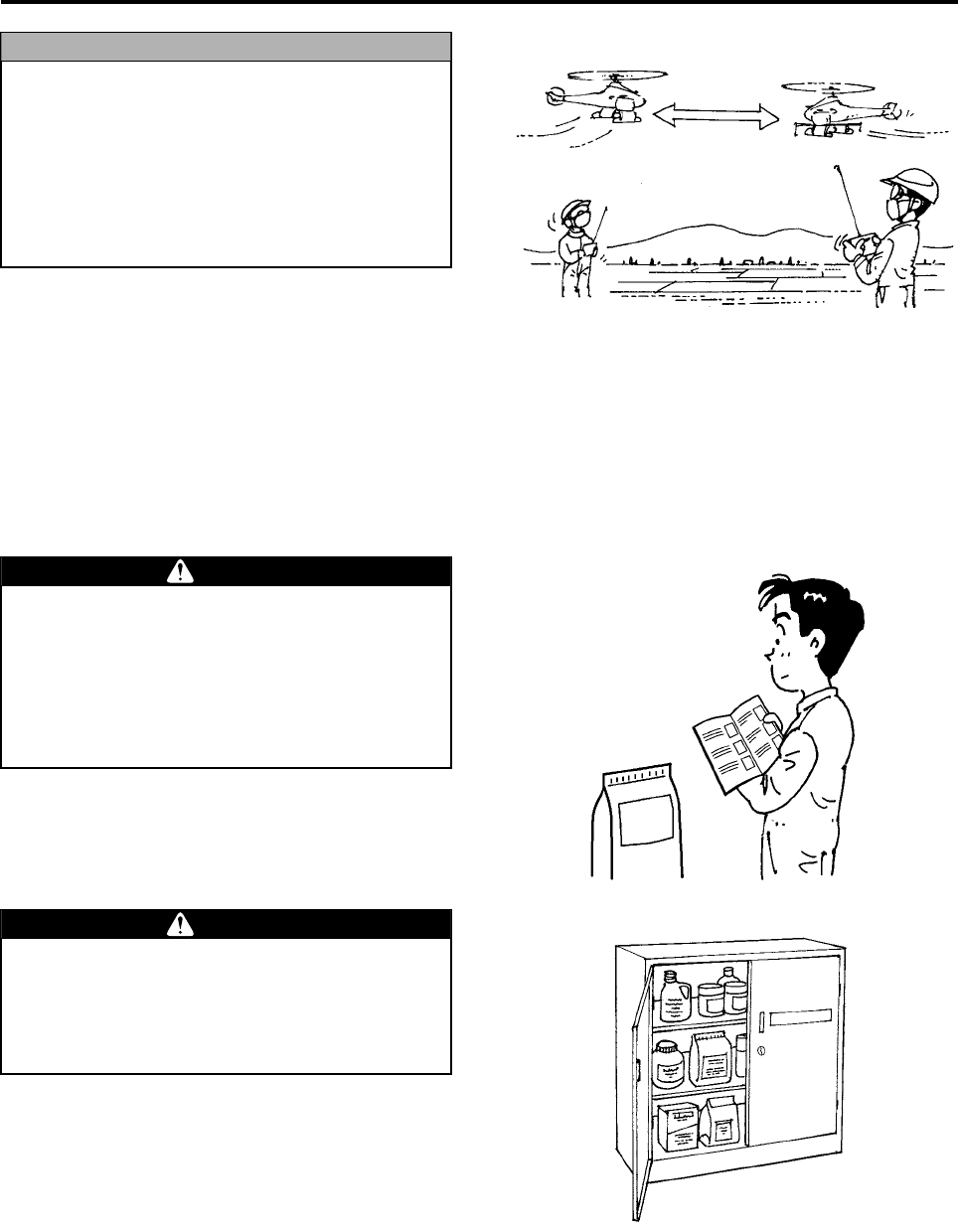
When operating 2 or more helicopters in a
given area, make sure to use separate radio-
wave frequencies and maintain a minimum
distance of 200 m between them.
If they approach within 200 m of each other,
check the frequency of the other helicopter,
and if it is a neighboring frequency, wait until
the other helicopter passes.
NOTICE
Over 200m
When using chemicals, make sure to follow
the instructions given on their labels. Do not
use chemicals other than those that have
been registered for aerial application. Failure
to do so could expose animals, plants, or
people to chemicals for which the operator
will be required to take social responsibility.
WARNING
Control and handle chemicals strictly in
accordance with their manuals. Negligent
control and improper handling of chemicals
could lead to chemical pollution or health
hazards.
WARNING
RMAX.book Page 11 Tuesday, January 17, 2012 3:06 PM

Part Names
Helicopter Exterior ..................................................................... 2-1
Helicopter Exterior Part Names .........................................................2-1
Control Panel and Warning Lights ....................................................2-2
Helicopter Interior ...................................................................... 2-3
Flight Transmitter ...................................................................... 2-4
2
RMAX.book Page 1 Tuesday, January 17, 2012 3:06 PM
2-1
Part Names
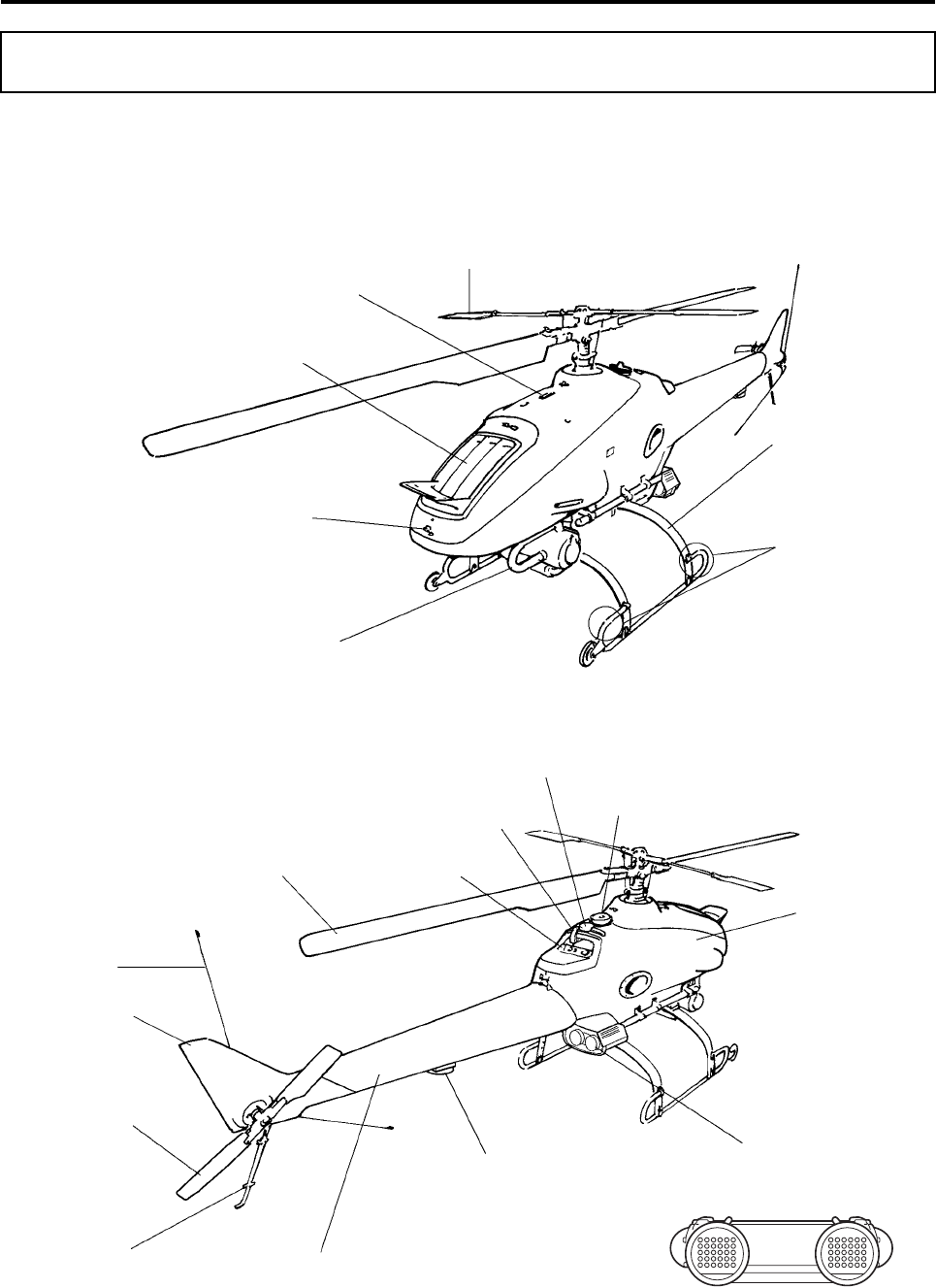
Helicopter Exterior Part Names
Helicopter Exterior
GPS
Indicator Light
YACS
Warning Light
Stabilizer Blade
Starter Lever
(P5-5)
Radiator
Rubber Hooks (7 locations)
(P4-16)
Muffler
Leaf
Main Rotor Blade
(P4-15)
GPS Unit
Tail Body
Azimuth Sensor
Tail Rotor Blade (P4-22)
Antenna
Stone Guard (P4-7)
Control Panel (P2-2)
Decompression
Lever (P5-5)
GPS Antenna
Fuel Tank Cap
Side Cover (P4-16)
Runner (P4-6)
Tail Cover
RMAX.book Page 1 Tuesday, January 17, 2012 3:06 PM
Part Names
2-2
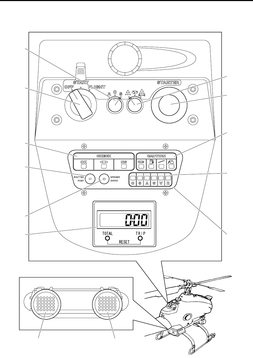
Control Panel and Warning Lights
Flight Mode
Selector Switch
(P4-13)
Main Switch
(P5-3)
Flight Indicator
(P3-5)
Shutter Pump
Cleaning Switch
Spinner Con-
stant Rotation
Switch
Starter Switch
(P5-6)
Check Point
Indicator
(P3-5)
Malfunction
Area Indicator
(P3-6)
Hour Meter
(P4-14)
Red Orange
YACS Warning Light
(P3-7) GPS Indicator Light
(P3-9)
Self Monitor
(P3-5)
Sprayer Selec-
tor Switch
(P4-3)
RMAX.book Page 2 Tuesday, January 17, 2012 3:06 PM
Part Names
2-3
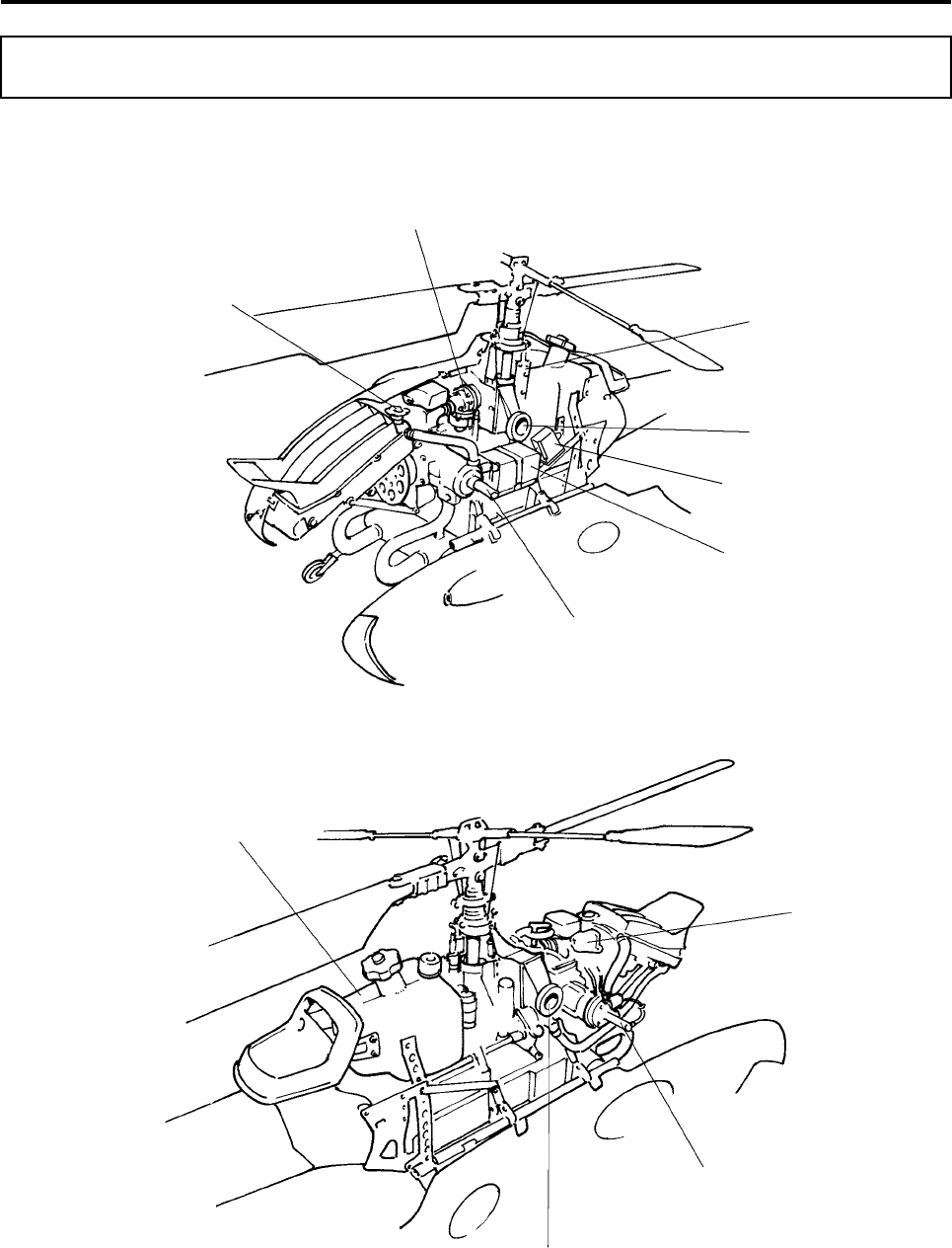
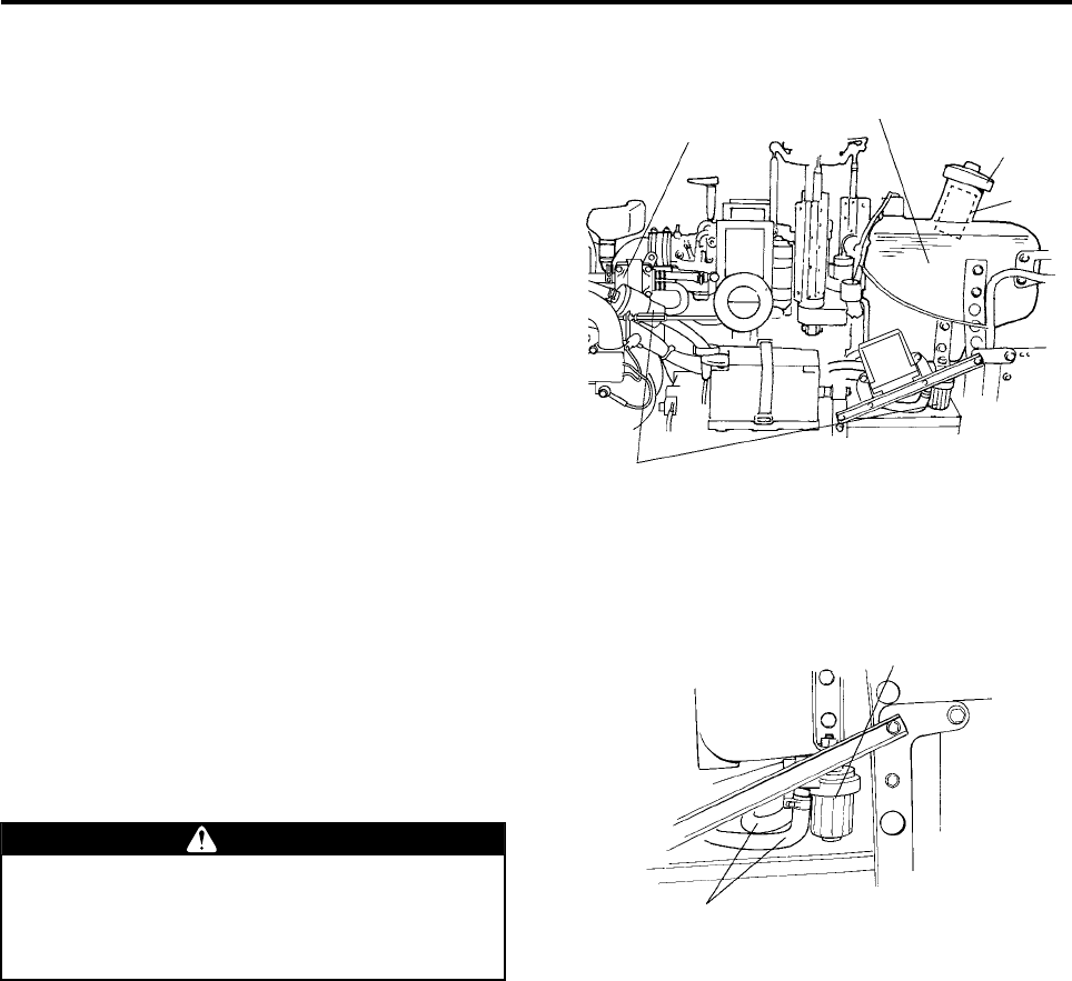
Helicopter Interior
Carburetor
Radiator Cap
Plug Cap (left)
Battery (P7-1)
Air Cleaner Air Inlet (left)
Slide Servo
Fuel Tank (P4-19)
Recovery Tank
(P4-20)
Air Cleaner Air Inlet (right)
Plug Cap (right)
Slide Servo Thermo Sensor
RMAX.book Page 3 Tuesday, January 17, 2012 3:06 PM
Part Names
2-4
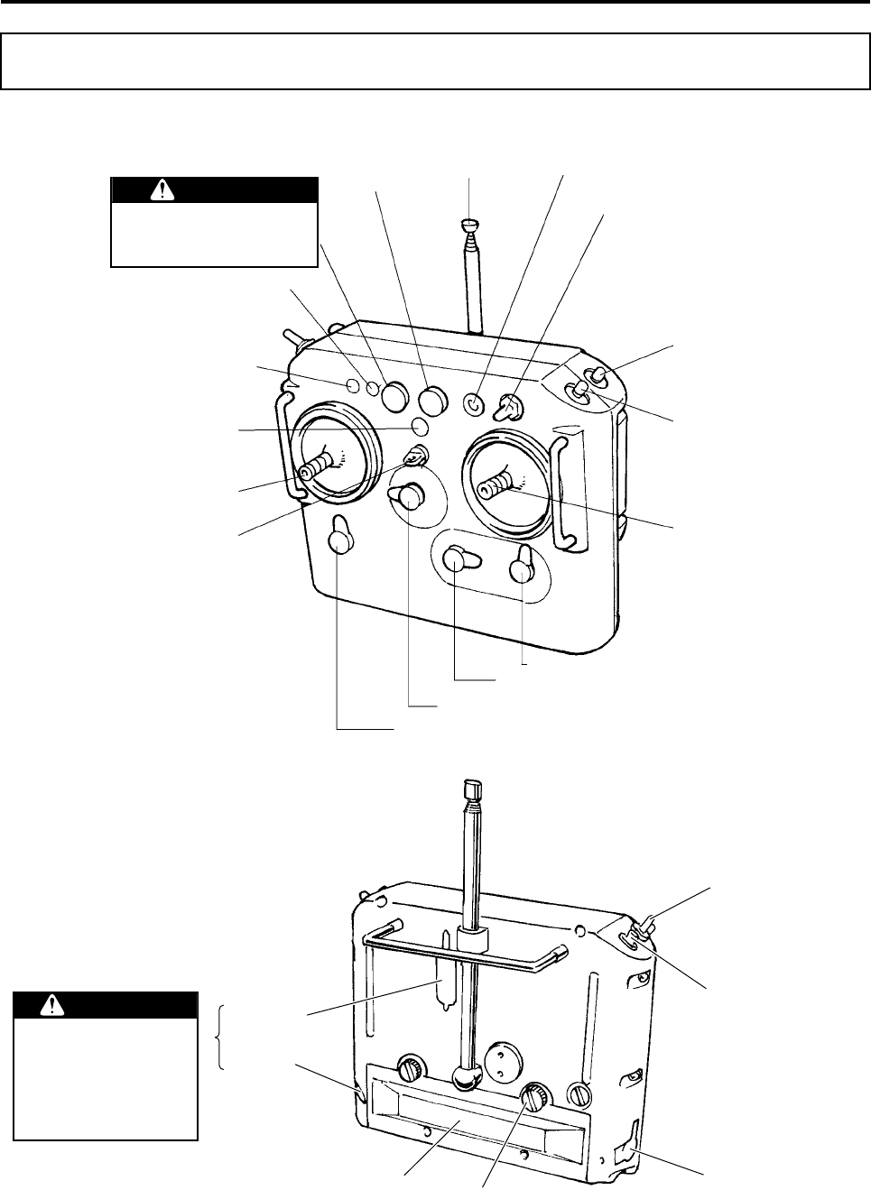
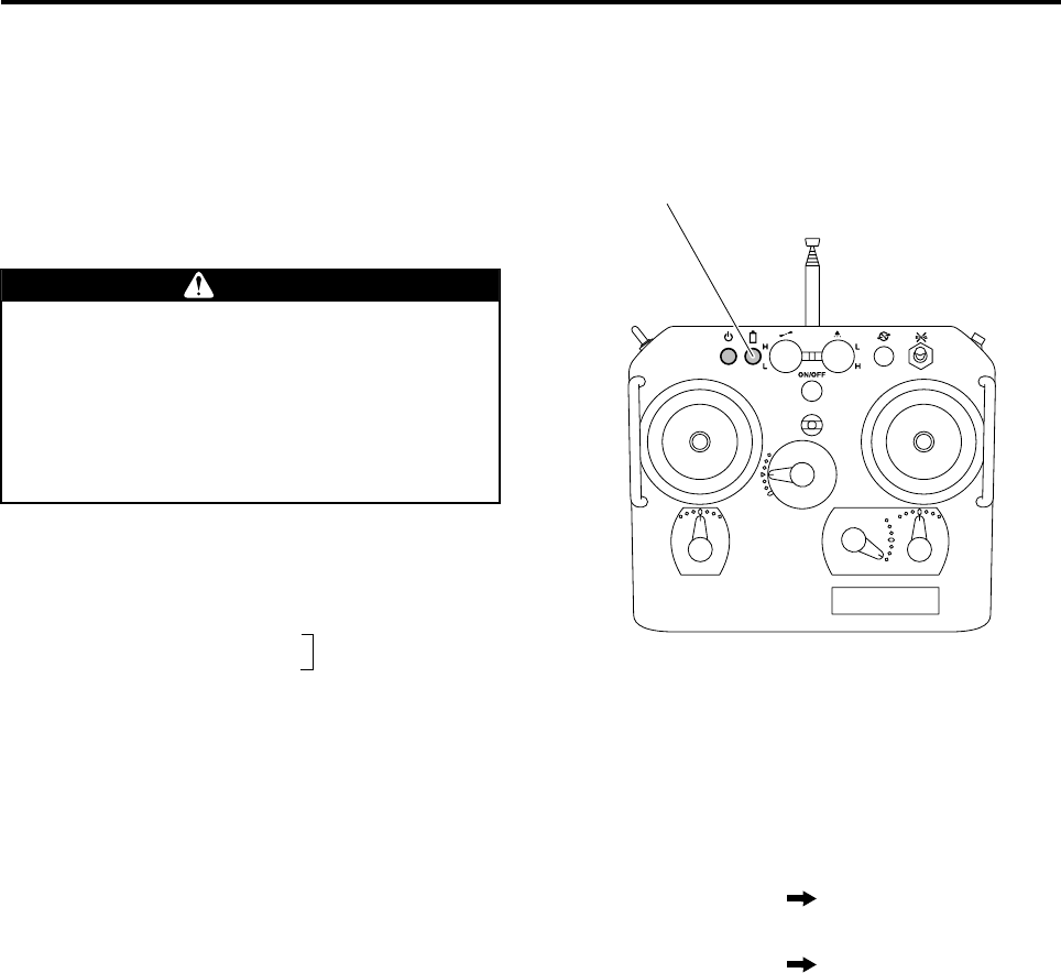
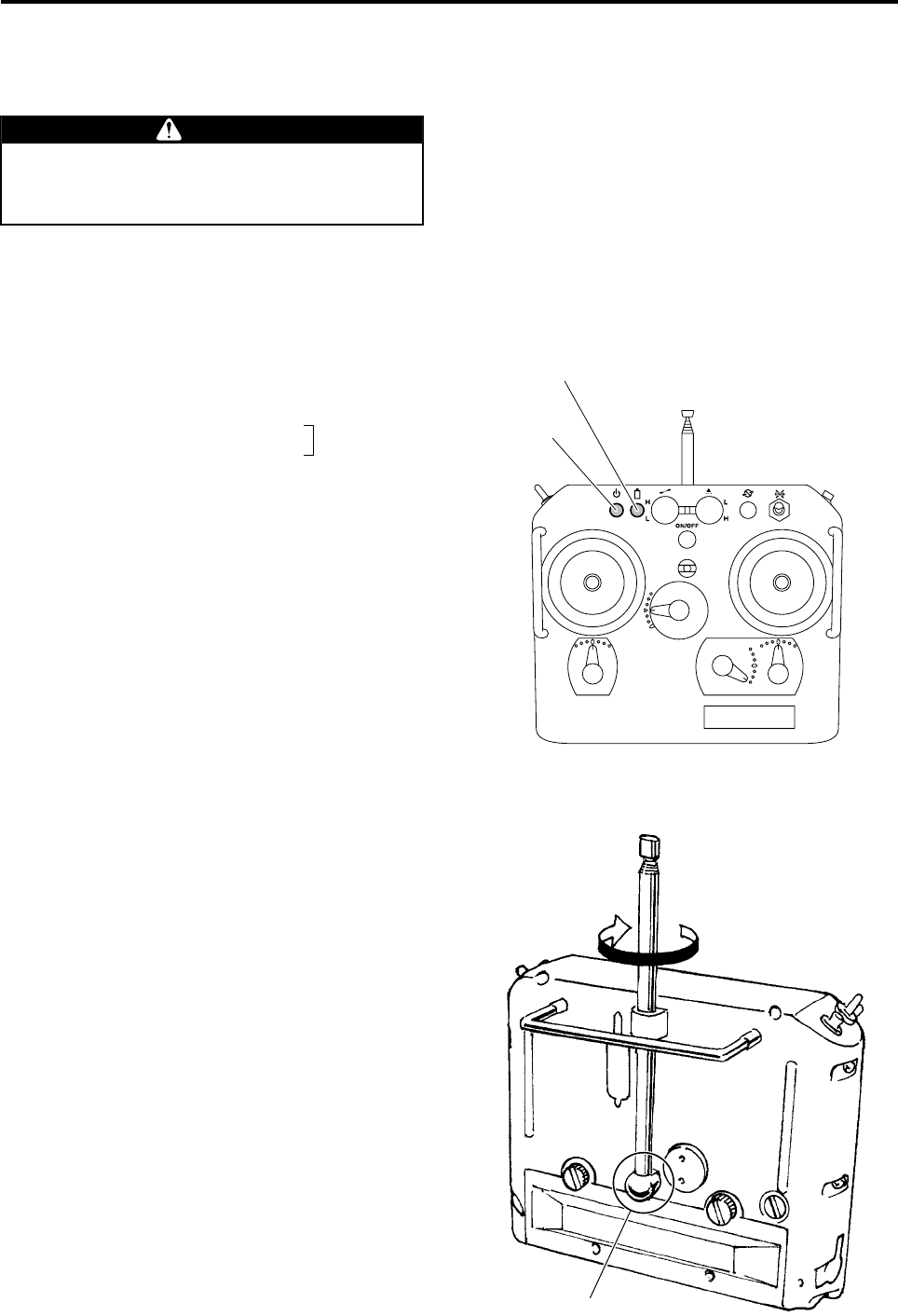
Flight Transmitter
Output Light (P4-18)
Battery Monitor Light (P3-11)
Spray Volume
Adjuster Antenna (P4-18) Rotor Brake Switch (P5-11)
Engine Stop Switch (P5-11)
Spray Switch (P3-4)
Throttle/Aileron Stick
Aileron Trim Lever
Throttle Trim Lever
Elevator Trim Lever
Rudder Trim Lever
Power Switch
Elevator Rudder Stick
Belt Hook
Transmission
Adjustment Dip Switch
GPS Control Switch
(P4-13)
YACS Control Switch
(P4-13)
Charging Jack (P4-1)
Battery Cover Screw (P4-2)
Transmitter Battery (inside)
(P4-2)
Communication
Jack
Spray Volume Switch
Do not tamper with these
areas, as these are intended
for changing the transmitter
settings.
Tampering with them could
render the helicopter out of
control, and could lead to an
accident.
WARNING
Rotor Speed Adjuster
The Adjuster has been adjusted
at the factory.
Please do not tamper with it,
as it could cause accidents.
WARNING
RMAX.book Page 4 Tuesday, January 17, 2012 3:06 PM

Part Names
2-5
RMAX.book Page 5 Tuesday, January 17, 2012 3:06 PM

Pre-Flight Inspection Items
Basic Transmitter Operation .................................................... 3-1
Basic Flight Transmitter Stick Operation and
Helicopter Movement .........................................................................3-1
Basic Flight Transmitter Trim Lever Operation and
Helicopter Movement .........................................................................3-2
YACS Control Switch ........................................................................3-3
GPS Control Switch ...........................................................................3-3
Spray Switch .......................................................................................3-4
Warnings (Warning Lights and Indicators) and Actions ........ 3-5
Self Monitor .........................................................................................3-5
Slide servo thermo sensor ................................................................3-6
YACS Warning Light (red) .................................................................3-7
GPS Indicator Light (Orange) ...........................................................3-9
Transmitter Battery Monitor Light ..................................................3-11
Failsafe (Safety Function During Radio Signal
Interference) Actions ............................................................... 3-12
Safety Features and Actions During Poor GPS
Signal Reception ...................................................................... 3-15
3
RMAX.book Page 1 Tuesday, January 17, 2012 3:06 PM
3-1
Pre-Flight Inspection Items
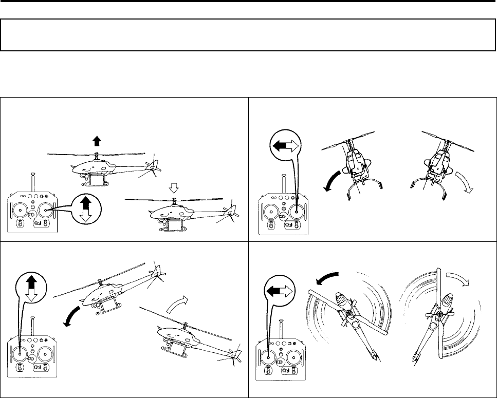
Basic Flight Transmitter Stick Operation and Helicopter Movement
Basic Transmitter Operation
(a) Throttle Operation (b) Aileron Operation
(c) Elevator Operation (d) Rudder Operation
Descent
Ascent
Tilt Left
(to turn left) Tilt Right
(to turn right)
Nose Down
(to go forward)
Nose Up
(to go backward)
Nose Left Nose Right
RMAX.book Page 1 Tuesday, January 17, 2012 3:06 PM
Pre-Flight Inspection Items
3-2
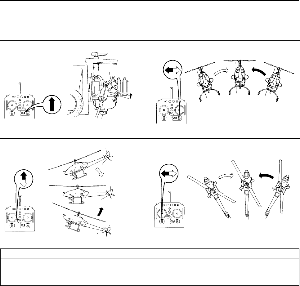
Basic Flight Transmitter Trim Lever Operation and Helicopter Move-
ment
(a) Throttle Trim Lever (b) Aileron Trim Lever
(c) Elevator Trim Lever (d) Rudder Trim Lever
Increases idling speed
Throttle Valve
Carburetor
Stops drifting
to the left Stops drifting
to the right
Stops drifting
forward
Stops drifting
backward
Stops counter-
clockwise spin Stops clockwise
spin
●The throttle trim lever is normally at the lowest position, and the aileron, elevator, and rudder trim
levers are normally at center position.
●Fine-tune these positions according to your situation. (See page 5-9.)
TIP
Chap3.fm Page 2 Wednesday, January 18, 2012 10:17 AM
Pre-Flight Inspection Items
3-3
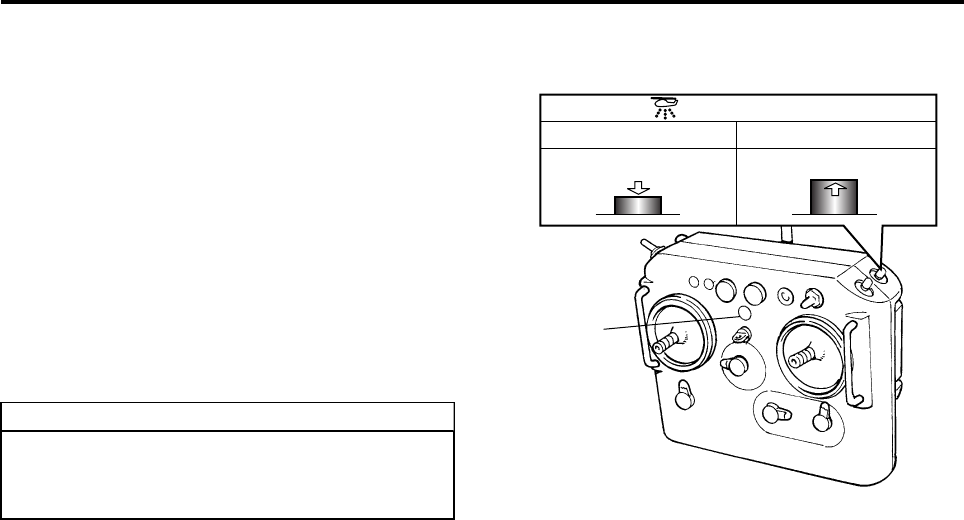
YACS Control Switch
In the event of a failure in the control system, the
YACS control switch enables the operator to switch
the control to manual mode, similar to piloted air-
craft. Normally, this is kept “ON”.
If the control system fails despite its various built-in
safety features, calmly turn this switch OFF and
land the helicopter at a safe location in manual
mode.
When the YACS control switch is OFF, the buzzer in
the transmitter will emit a “beep-beep” sound to
inform the operator that control is in manual mode.
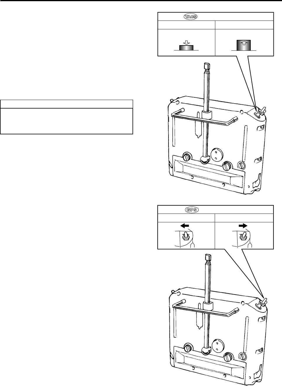
GPS Control Switch
The GPS control switch is used for switching
between the following modes: A ⇔ AG, C ⇔ CG, S
⇔ SG. (See page 4-13.)
Before turning ON the GPS control switch, make
sure that the outer lights of the GPS indicator are
illuminated. If the GPS indicator lights are OFF or
flashing, the GPS control flight mode cannot be
used even when the GPS control switch is turned
ON.
Moreover, in the situations described below, first
turn OFF the switch, then turn it back ON. Other-
wise, the GPS control flight mode cannot be used.
•GPS control communication has been interrupted
because the helicopter has landed.
•The GPS control switch was ON even before
takeoff.
•GPS control has been interrupted due to poor
GPS signal reception.
•GPS control has been interrupted because it has
been set to manual mode.
Turning the YACS control switch OFF
switches to manual mode. Do not confuse
with other switches while operating.
TIP
Push
Control OFF (manual) Control ON
Release
YACS Control Switch
Control OFF Control ON
OFF ON OFF ON
GPS Control Switch
RMAX.book Page 3 Tuesday, January 17, 2012 3:06 PM
Pre-Flight Inspection Items
3-4
Spray Switch
The sprayer can be operated when the power
switch of the flight transmitter is ON and the main
switch on the helicopter is in the START or FLIGHT
position.
Change the spray switch settings as described
below, depending on how you wish to operate the
sprayer.
Using the Flight Transmitter:
Press the (ON/OFF) spray switch on the flight
transmitter ON (pushed in) to operate the sprayer.
Press the switch again (released) to stop the
sprayer.
Pay attention to the surroundings before
pressing the spray switch ON, which will dis-
charge chemicals.
TIP
Push
ON (to operate) OFF (to stop)
Release
Spray Switch
Power Switch
RMAX.book Page 4 Tuesday, January 17, 2012 3:06 PM
Pre-Flight Inspection Items
3-5
This product features various types of safety func-
tions. Thoroughly familiarize yourself with these
functions and the meaning of the warnings and indi-
cations before a flight, and take appropriate
actions.
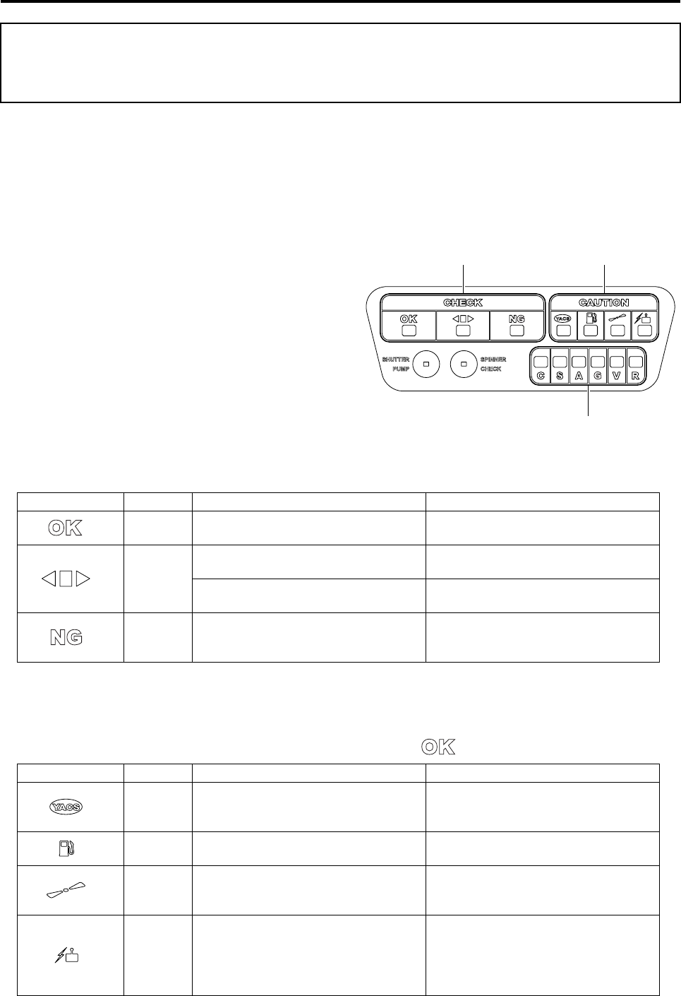
Self Monitor
The self monitor, which is located on the control
panel, indicates the conditions of the various areas
of the helicopter.
1 Flight Indicator
Indicates whether the helicopter is able to fly.
2 Check Point Indicator
An indicator will illuminate if a malfunction is discovered on the helicopter while a configuration or a flight is
in progress.
The malfunction areas indicated here can be handled by the user. Take appropriate actions to respond to
the lights that are lit, and check that the flight indicator 1 shows “”.
Warnings (Warning Lights and Indicators) and
Actions
3
12
Item Light Meaning Action
ON Able to fly in the YACS-controlled flight
mode. OK to fly
ON
Setting YACS control and self-check-
ing. Wait until the configuration is com-
plete.
Control is in manual mode. Turn ON the YACS control switch on
the transmitter.
ON A malfunction has been discovered
through a self-check.
Check the indicators 2 and 3 to identify
the area of the malfunction and take
appropriate actions.
Item Light Meaning Action
Flashing Flashes approximately 3 times (10
seconds) when the main switch is
switched from OFF to START.
Wait until the configuration is complete
(light OFF).
ON The remaining fuel is below specifica-
tion level. Refuel.
ON The engine speed has dropped due to a
high-load condition caused by exces-
sive payload or rough maneuvering, etc.
Reduce the payload, or fly the helicop-
ter more gently.
ON Because no control signals were
received, the failsafe control took over.
Check whether the power switch of the
transmitter is ON. Once this indicator
light illuminates, it will continue to illu-
minate until the main switch on the
helicopter is turned OFF.
RMAX.book Page 5 Tuesday, January 17, 2012 3:06 PM
Pre-Flight Inspection Items
3-6
3 Malfunction Area Indicator
An indicator will illuminate or flash if a malfunction is discovered on the helicopter while a configuration or a
flight is in progress.
The malfunction areas indicated here cannot be handled by the user. Contact your dealer to describe the
symbol for the light that has turned ON or is flashing, and request a repair.
Once one of these indicator lights illuminates, it will continue to illuminate or flash until the main switch is
turned OFF.
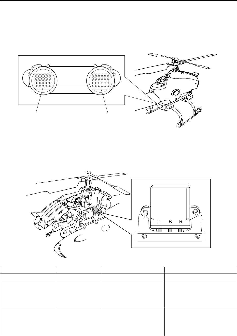
Slide servo thermo sensor
The slide servo thermo sensor indicates the temperature state of the slide servo motor.
It will flash when the temperature rises abnormally, or when a malfunction is detected in the thermo sensor.
* It may be difficult to see the LED under direct sun light.
If the temperature of the slide servo has risen, the LED will return to the ON state once the temperature
drops after time has passed. If the thermo sensor has a malfunction, it will continue to flash.
Indication State Meaning Action
ON Normal state
Flashing (Alternates repeat-
edly between ON for
1 second and OFF
for 1 second)
The slide servo temperature
has risen, causing an abnor-
mal state. The malfunction
areas indicated here cannot
be handled by the user.
Contact your dealer immediately
to notify which LED is flashing (L/
B/R), and request a repair.
Intermittent flashing (Alternates repeat-
edly between 0.1
second of ON and
1.9 second of OFF)
The thermo sensor has a
malfunction. The malfunc-
tion areas indicated here
cannot be handled by the
user.
Contact your dealer immediately
to notify which LED is intermit-
tently flashing (L/B/R), and
request a repair.
YACS Warning Light GPS Indicator Light
RMAX.book Page 6 Tuesday, January 17, 2012 3:06 PM
Pre-Flight Inspection Items
3-7
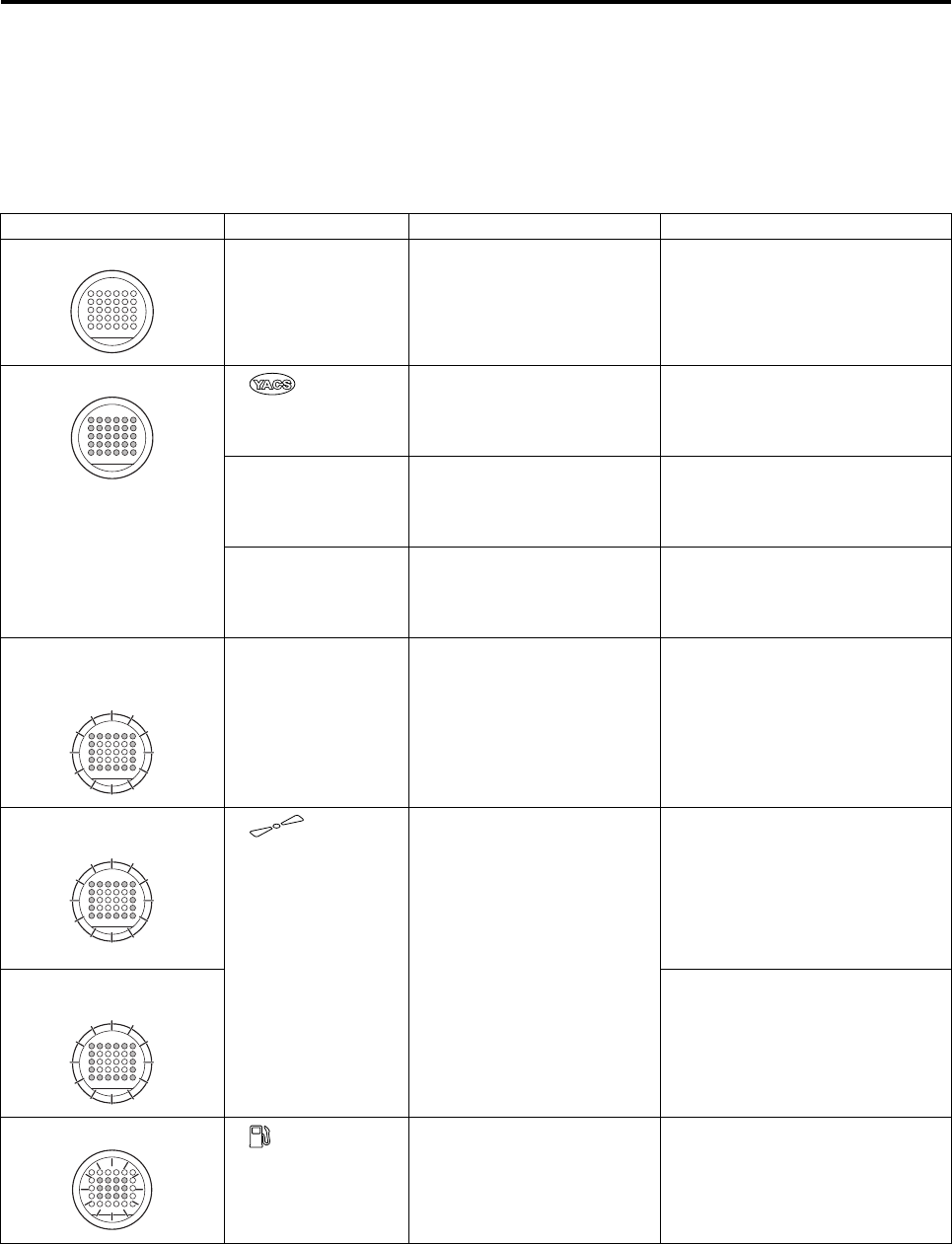
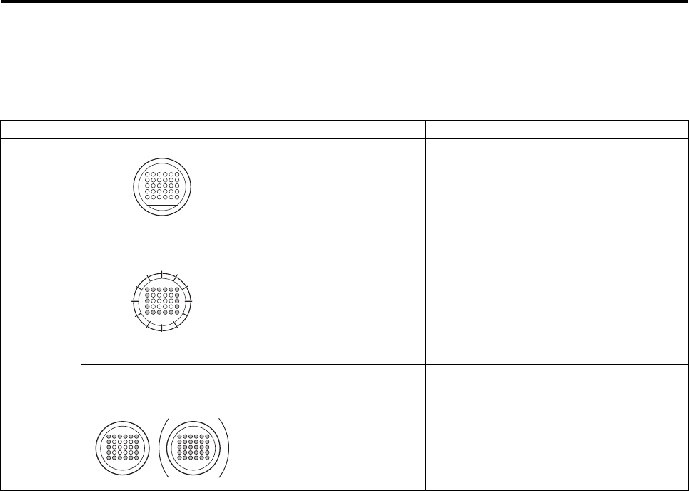
YACS Warning Light (red)
If a malfunction is discovered on the helicopter while the YACS control is being configured or a flight is in
progress, the YACS warning light (red) illuminates or flashes in unison with the self monitor, and provides the
operator a description of the warning.
If this light illuminates or flashes during a flight, calmly take the appropriate actions in accordance with the
description of the warning.
Indication Self Monitor Status Meaning Action
All OFF No malfunction OK to fly
All ON(*1) “” flashing YACS control is being config-
ured. Wait until the configuration is
complete (approx. 10 sec). During
this time, check for blown bulb in
the YACS warning light.
One of the malfunc-
tion area indicators
illuminates
Control has been switched to
manual mode due to a mal-
function.
Calmly land the helicopter in a
safe area, contact your dealer to
report which indicator is lit on the
self monitor, and request a repair.
No display on self
monitor; thermo
sensor flashing
The slide servo has heated
up abnormally, or the thermo
sensor has a malfunction.
Calmly land the helicopter in a
safe area. If there is no indication
on the self monitor, take actions
described on page 3-6.
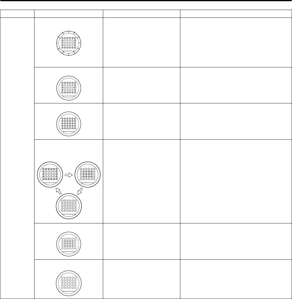
Only outer lights flash
(for 15 sec after starting
engine)
After the engine has started,
for 15 sec. OK to fly after flashing has
stopped and all lights are OFF.
(See page 5-8.)
Only outer lights flash
(3 times) “” illuminat-
ing
A high load has been applied
due to reasons 1 to 3,
causing the engine speed to
drop or the rudder to move
considerably in one direction.
1Excessive payload.
2Rough maneuvering
3Effects from strong wind,
etc.
1Calmly land the helicopter in a
safe area and reduce the pay-
load. (See page 4-10.)
2Operate the helicopter more
gently.
3Fly at a wind velocity of 3 m/s
or less.
Only outer lights flash
(Continuous flashing) If the lights flash more than 3
times, the stability in the rudder
direction will deteriorate.Turn the
OFF YACS control switch and turn
it back ON to recover from this
condition.
Only inner lights flash “” is ON The remaining fuel is below
specification level. Calmly land the helicopter in a
safe area and refuel. (See page 4-
4.)
RMAX.book Page 7 Tuesday, January 17, 2012 3:06 PM
Pre-Flight Inspection Items
3-8
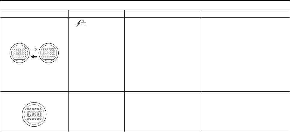
*1: The “All ON” state will take precedence over other states (i.e., when all lights are ON, no flashing will take
place to indicate other concurrent states).
Inner and outer lights
flash alternately
(3 times)
“” is ON Because no control signals
were received, the failsafe
control took over.
Take appropriate actions in accor-
dance with “Failsafe (Safety Func-
tion During Radio Signal
Interference) Actions”. (See page
3-12.)
If the helicopter responds immedi-
ately to control, calmly land it in a
safe area. Then, check for radio
signal interference (P4-9) and
conduct a radio signal distance
test (P4-25).
Only outer lights are ON Flight velocity has exceeded
20km/h. Fly at a velocity of 20km/h or less.
(See page 5-10.)
Indication Self Monitor Status Meaning Action
RMAX.book Page 8 Tuesday, January 17, 2012 3:06 PM
Pre-Flight Inspection Items
3-9
GPS Indicator Light (Orange)
The GPS indicator lights (orange) illuminates or flashes to inform the operator of the reception conditions of
the GPS signals and the state of GPS control.
Take the appropriate actions in accordance with the description of the warning.
Condition Indication Meaning Action
Before
starting
engine
All OFF Preparing GPS control set-
tings (awaiting completion of
YACS control configuration)
Wait until the completion of YACS control
configuration (when all YACS warning lights
turn OFF).
If the outer lights do not flash after the
YACS control configuration has completed,
there may be an equipment failure.
Only outer lights flash GPS control is being config-
ured. GPS control is being prepared. Fly the heli-
copter by using only YACS control or wait
for the GPS control configuration to com-
plete (the outer lights illuminate).
If the outer lights do not illuminate after 3
minutes, the GPS signal reception might be
poor. Therefore, fly the helicopter by using
only YACS control.
Only outer lights are ON
(all lights illuminate with
GPS control switch ON)
GPS control configuration is
complete. The GPS control settings have been com-
pleted and the GPS control is for use.
Turn the GPS control switch ON and check
that all the lights are lit.
RMAX.book Page 9 Tuesday, January 17, 2012 3:06 PM
Pre-Flight Inspection Items
3-10
After start-
ing engine Only outer lights flash GPS signal reception is good
but GPS control cannot be
used due to reason 1 or 2.
1Before takeoff / after land-
ing
2Control is in manual mode
In case of reason 1, the outer lights will
change from flashing to steady ON after
takeoff.
In case of reason 2, turn ON the YACS
control switch on the transmitter.
Only outer lights are ON GPS signal reception is
good.
GPS control is not being
used.
GPS control is ready for use. To use it, turn
ON the GPS control switch on the transmit-
ter.
All lights ON GPS signal reception is
good.
GPS control is being used.
The flight is under GPS control.
Repeated cycle of “outer
lights ON > inner lights
ON > OFF”.
GPS signal reception has
worsened and GPS control
cannot be used.
The flight mode switches automatically to
YACS control. Calmly operate the flight.
When using the SG mode, the light turns
ON and the brake control will be applied
automatically according to speed, only in
the longitudinal direction of the helicopter.
(See page 3-15.)
Turn OFF the GPS control switch on the
transmitter to stop the flashing of the lights.
Only inner lights are ON GPS control without gyro
sensor Turn the GPS control switch OFF, and fly
under YACS control.
All OFF GPS control cannot be used
due to poor GPS signal
reception.
Operate the flight under YACS control until
the GPS signal reception improves (and the
outer lights illuminate).
Condition Indication Meaning Action
RMAX.book Page 10 Tuesday, January 17, 2012 3:06 PM
Pre-Flight Inspection Items
3-11
Transmitter Battery Monitor Light
If the voltage of the transmitter battery drops below
a certain level during operation, a warning buzzer
(3 beeps) will sound every 2 seconds and the bat-
tery monitor light on the transmitter will flash. If you
are flying the helicopter at this time, land it immedi-
ately and recharge or replace the transmitter bat-
tery.
The charging status of the battery can be moni-
tored by the sound of the buzzer when the power of
the transmitter is turned ON.
In addition, the transmitter also has the following functions to inform the operator of the transmitter status.
If the battery monitor light illuminates on the
transmitter, it is a final warning indicating
that the transmitter battery has been
depleted. Immediately land the helicopter
and replace the transmitter battery. Failure to
do so could render the helicopter out of con-
trol.
Beep beep beep beep (4 times) Fully charged
Beep beep beep (3 times)
Beep beep (2 times) Requires charg-
ing.
Beep (1 time) Inoperable unless
charged.
WARNING
Battery Monitor Light
1) Beep-beep once every 2 seconds The control is in manual mode because the
YACS control switch is turned OFF. Turn ON the YACS control
switch.
2) Beep-beep-beep
Beep-beep-beep
Beep-beep-beep-beep-beep-beep-beep
(3-3-7 pattern)
Operation may be poor due to a malfunc-
tion. Contact your dealer.
RMAX.book Page 11 Tuesday, January 17, 2012 3:06 PM
Pre-Flight Inspection Items
3-12
If the radio signals for controlling the flight do not reach the helicopter due to interference, the helicopter will be
rendered out of control, which creates a dangerous situation. In case of radio signal interference, the system
has a safety feature that alternately flashes the inner and outer lights of the red YACS warning lights and auto-
matically effects the flight control described on the following pages. Thoroughly familiarize yourself with this
feature to take the appropriate actions.
Failsafe (Safety Function During Radio Signal
Interference) Actions
During signal interference, never approach
the helicopter until the main rotor has come
to a complete stop and the engine has
stopped. If there are any people in the area,
instruct them to leave the area immediately.
DANGER
●Do not fly any higher than 3 to 4 m (above
the ground or crops). When radio signal
interference occurs (i.e. when failsafe
mode is engaged), the engine speed is
automatically brought to idling state after
40 seconds. Flying at a higher altitude will
cause the helicopter to descend abruptly.
●Make sure to follow the “Actions”
instructed in the manual. Failure to do so
could cause the helicopter to move unex-
pectedly or descend suddenly once it
recovers from the radio signal interfer-
ence, and could lead to an accident.
●Do not resume flying until you have veri-
fied and eliminated the cause of the radio
signal interference. Otherwise, you could
lose control of the helicopter again, lead-
ing to an accident. (See pages 4-9 and 4-
25.)
WARNING
RMAX.book Page 12 Tuesday, January 17, 2012 3:06 PM
Pre-Flight Inspection Items
3-13
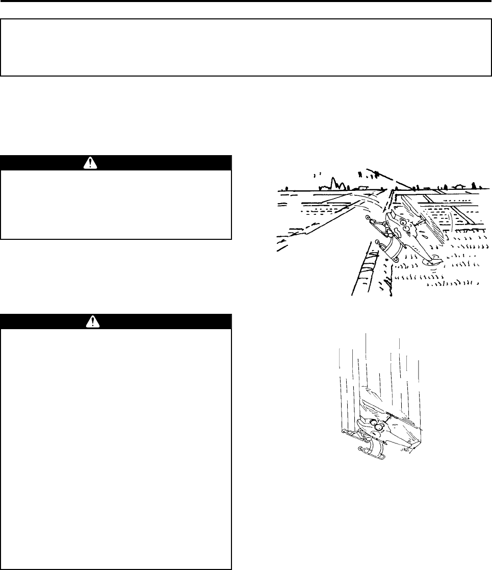
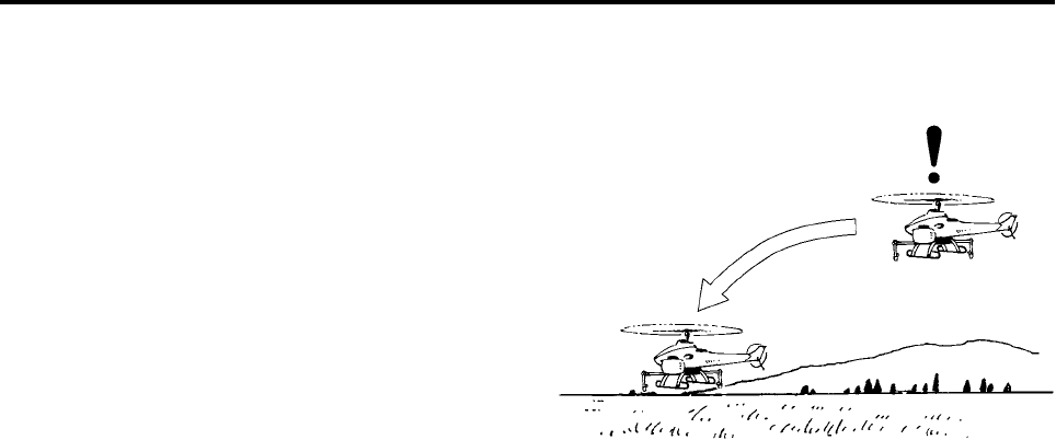
●Poor GPS Reception (Outer Lights of GPS
Indicator Light Are OFF)
1In the event of radio signal interference, the inner
and outer lights of the red YACS warning lights
will flash alternately and the system will force the
helicopter to descend quickly regardless of the
flight mode. If the control radio signals recover
while the helicopter is descending, the flight
mode will switch automatically to operator con-
trol. For this reason, calmly move all the sticks
on the transmitter to the neutral (center) position,
and wait for the signals to recover.
2If the helicopter is forced to land because the
radio signals have not recovered, the engine is
brought to idle.
Depending on the terrain, weather, and flight
conditions, the helicopter could overturn. If the
helicopter overturns, never approach the heli-
copter, as the engine speed might not decrease.
3After a forced landing, turn the throttle to the
slowest position and wait for the radio signals to
recover or the engine to stop.
4If the radio signals do not recover after 1 minute
from the time the radio signal interference
occurred, the engine will stop automatically. After
the rotor has come to a complete stop, approach
the helicopter and turn OFF its main switch.
Radio signal interference!
(Inner and outer YACS warning
lights flash alternately.)
Descends quickly
RMAX.book Page 13 Tuesday, January 17, 2012 3:06 PM
Pre-Flight Inspection Items
3-14
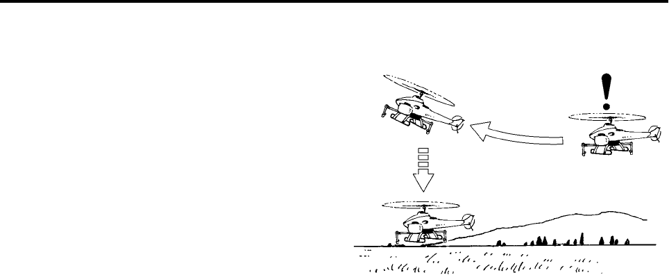
●Good GPS Reception (Outer Lights of GPS
Indicator Light Are ON)
1When radio signal interference occurs, the inner
and outer lights of the red YACS warning lights
will flash alternately, and the system will apply
the brake and force the helicopter to hover
regardless of the flight mode. Then, the helicop-
ter will automatically start descending slowly. If
the control radio signals recover while the heli-
copter is descending, the flight mode will switch
automatically to operator control. For this rea-
son, calmly move all the sticks on the transmitter
to the neutral (center) position, and wait for the
signals to recover.
2If the helicopter is forced to land because the
radio signals have not recovered, the engine is
brought to idle.
Depending on the terrain, weather, and flight
conditions, the helicopter could overturn. If the
helicopter overturns, never approach the heli-
copter, as the engine speed might not decrease.
3After a forced landing, turn the throttle to the
slowest position and wait for the radio signals to
recover or the engine to stop.
4If the radio signals do not recover after 1 minute
from the time the radio signal interference
occurred, the engine will stop automatically.
After the rotor has come to a complete stop,
approach the helicopter and turn OFF its main
switch.
Descends slowly after
hovering Brake control
Radio signal interference!
(Inner and outer YACS warning
lights flash alternately.)
RMAX.book Page 14 Tuesday, January 17, 2012 3:06 PM
Pre-Flight Inspection Items
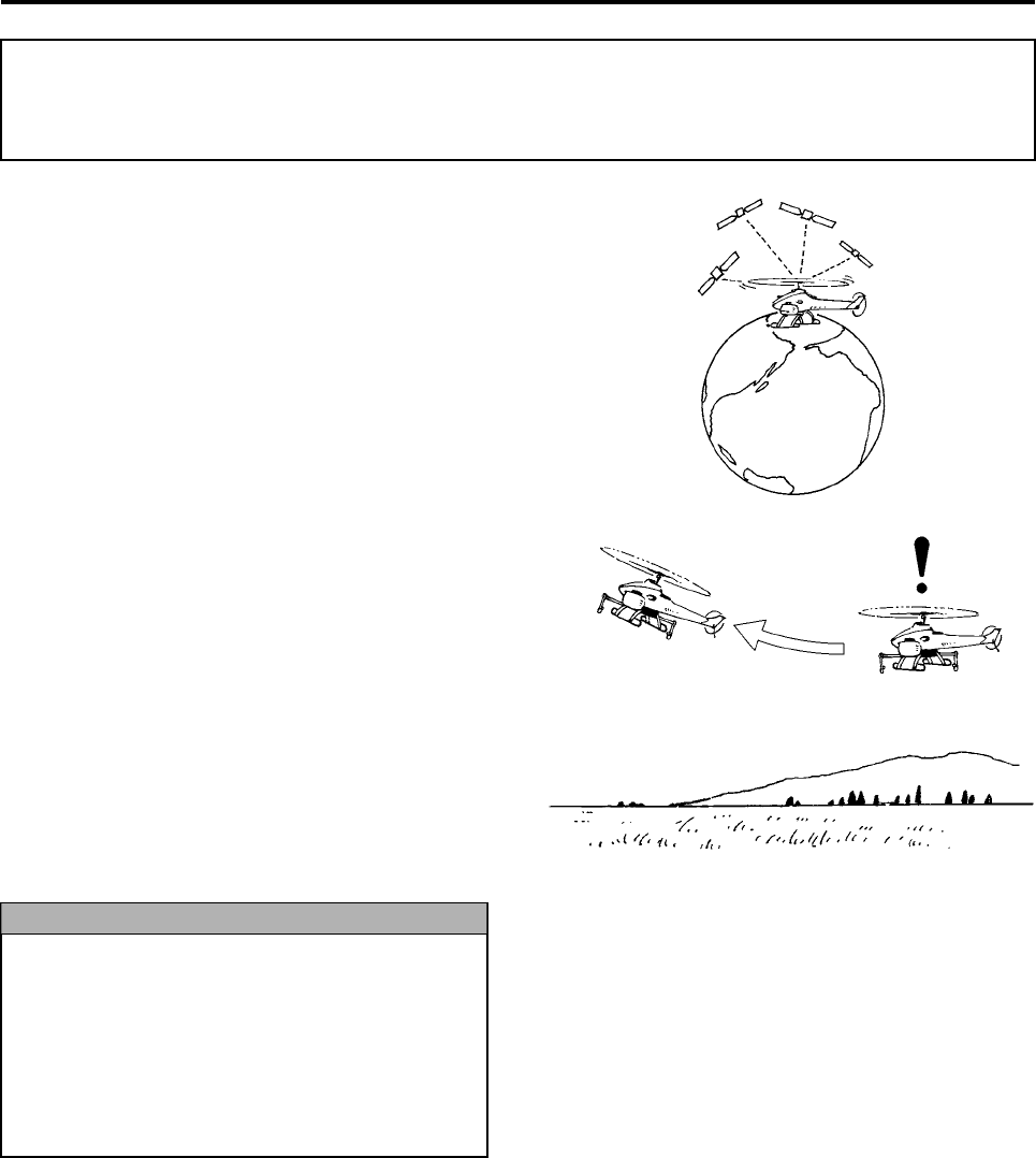
3-15
The GPS control operates by receiving radio sig-
nals from 4 or more satellites. It may become inop-
erable depending on the surroundings, terrain,
weather conditions, time zone, and other reasons.
If the reception of GPS signals becomes poor while
operating in a GPS control flight mode (SG, CG, or
AG), a safety feature will cause the outer and inner
lights of the orange GPS indicator lights to flash
alternately. Then, the system will automatically
effect flight control or switch the flight mode as
described below. Thoroughly familiarize yourself
with this feature to take the appropriate actions.
●Operating in SG mode
As the GPS signal reception worsens, the orange
GPS indicator lights will cycle through “outer lights
ON > inner lights ON > OFF”, and the brake control
will be applied only in the longitudinal direction of the
helicopter. At this point, quickly turn OFF the GPS
control switch. Because GPS control cannot be used
even before the GPS control switch is turned OFF,
the helicopter will operate in the slow flight mode.
This flight mode is not suitable for aerial application.
In addition, GPS control will not resume even if the
GPS signal reception improves. When the GPS
control switch is turned OFF, the GPS indicator light
will turn OFF and control will switch to S mode.
Therefore, operate carefully.
●Operating in CG mode
As the GPS signal reception worsens, the orange
GPS indicator lights will cycle through “outer lights
ON > inner lights ON > OFF”. Control will switch
automatically to C mode. At this point, quickly turn
OFF the GPS control switch and operate carefully.
When the GPS control switch is turned OFF, the
GPS indicator light will turn OFF.
●Operating in AG mode
As the GPS signal reception worsens, the orange
GPS indicator lights will cycle through “outer lights
ON > inner lights ON > OFF”. Control will switch
automatically to A mode. At this point, quickly turn
OFF the GPS control switch and operate carefully.
When the GPS control switch is turned OFF, the
GPS indicator light will turn OFF.
Safety Features and Actions During Poor GPS
Signal Reception
If the stick on the transmitter is moved past
the neutral (center) position to stop the heli-
copter when it is flying forward or backward
in SG mode, the automatic brake control will
be applied together with the operator’s brake
control if the GPS control is canceled. As a
result, the nose of the helicopter will tilt up to
an excessive angle.
NOTICE
Brake control Poor GPS reception!
(Warning pattern on GPS
indicator light)
RMAX.book Page 15 Tuesday, January 17, 2012 3:06 PM
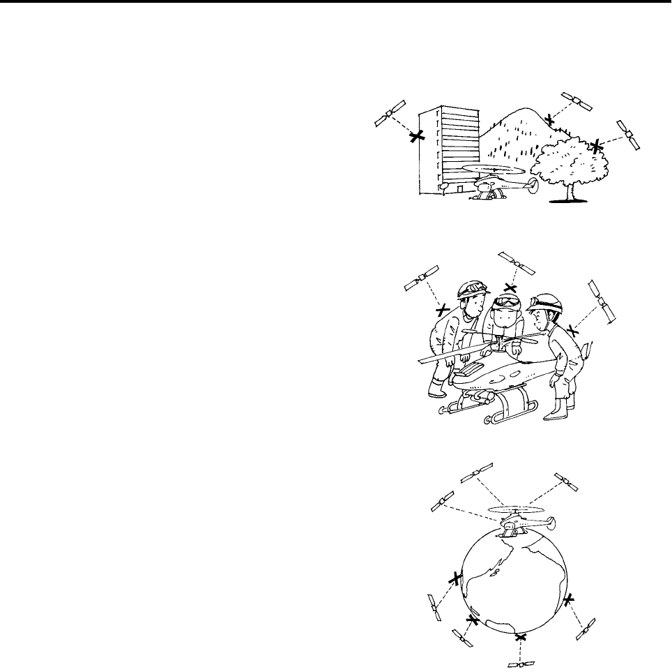
Pre-Flight Inspection Items
3-16
The reception of GPS radio signals can be
adversely affected by conditions indicated below or
due to other reasons.
1Flying near obstacles such as mountains, trees,
or buildings.
2The antenna is surrounded by people.
3Fewer satellites are available during certain time
slots.
RMAX.book Page 16 Tuesday, January 17, 2012 3:06 PM

Pre-Flight Inspection Items
3-17
RMAX.book Page 17 Tuesday, January 17, 2012 3:06 PM

Pre-Flight Preparation and Inspection
Preparation Up to the Day Before ............................................ 4-1
Recharging and Replacing Flight Transmitter Battery ...................4-1
Selecting and Setting the Sprayer ....................................................4-3
Preparing Fuel and Refueling ............................................................4-4
Preparation on the Day of Flight .............................................. 4-6
Transporting Procedure .....................................................................4-6
Radio Signal Interference Inspection ...............................................4-9
Payload Inspection ...........................................................................4-10
Selecting the Flight Mode ................................................................4-13
Displaying and Recording Flight Hours .........................................4-14
Installing and Removing Main Rotor Blades .................................4-15
Installing and Removing Side Covers ............................................4-16
Pre-flight Inspection ................................................................ 4-17
Transmitter Inspection .....................................................................4-18
Fuel Inspection .................................................................................4-19
Coolant and Oil Inspections ............................................................4-20
Rotor Blade Inspection ....................................................................4-22
Servo and Linkage Inspection .........................................................4-23
Self Monitor Inspection ....................................................................4-24
Radio Signal Distance Test .............................................................4-25
Tail Rotor Drive Belt Inspection ......................................................4-25
GPS System Inspection ...................................................................4-26
4
RMAX.book Page 1 Tuesday, January 17, 2012 3:06 PM
4-1
Pre-Flight Preparation and Inspection
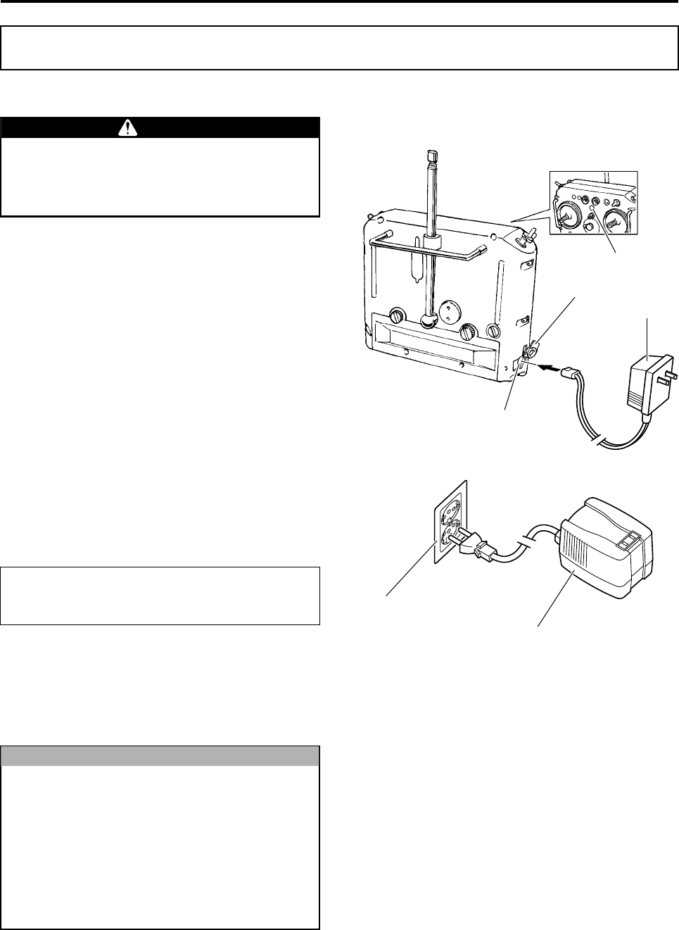
Recharging and Replacing Flight Transmitter Battery
Recharging the Battery
Make sure to use the dedicated battery recharger
for the transmitter, and recharge the battery as fol-
lows:
1Check that the power switch for the transmitter is
turned OFF.
2Remove the plug from the charging jack.
3Insert the recharger plug into the charging jack
on the back of the transmitter.
4Insert the power cord for the electrical trans-
former (AC 240V → AC 100V) into a power out-
let.
5Insert the recharger into the electrical trans-
former.
6The pilot lamp on the recharger illuminates to
indicate that the battery is being recharged.
The charging temperature range, recharging time,
and duration of use of the battery are as follows.
7After the battery has been recharged, make sure
to install the plug into the charging jack.
8The battery monitor function indicates the bat-
tery’s charge status and will alert the operator
during flight if the battery must be replaced. (See
page P3-11.)
Preparation Up to the Day Before
Make sure to use a fully charged battery for
the flight. Using an insufficiently charged
battery could render the helicopter out of
control.
Charging temperature range: 0-40 °C
Recharging time: 14-16 hours
Duration of use: 2.1-3.3 hours
The dedicated recharger has been designed
for use with AC 100V power outlets.
If the recharger is mistakenly connected
directly to an AC 240V power outlet, the
recharger and the transmitter could be dam-
aged. Therefore, use an electrical trans-
former (AC 240V → AC 100V) that conforms
to Australian standards when recharging the
battery.
WARNING
NOTICE
Plug
Recharger AC100V
Charging Jack
Power Switch
Power Outlet
Electrical Transformer AC240V→AC100V
AC240V
RMAX.book Page 1 Tuesday, January 17, 2012 3:06 PM
Pre-Flight Preparation and Inspection
4-2
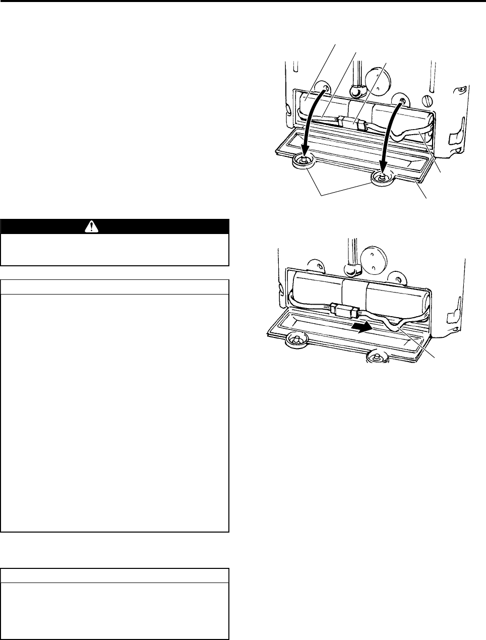
Replacing the Battery
Replace the battery as follows:
1Loosen the 2 retaining screws for the battery
cover on the back of the transmitter.
2Open the battery cover.
3Unplug the connector that connects the battery
lead wire and the extension lead wire.
4Pull out the battery.
5Insert the charged battery in such a way that its
lead wire is on your left hand side.
6Connect the battery lead wire and the extension
lead wire.
7Leave some slack in the extension lead wire.
8Close the battery cover, being careful not to
pinch the battery lead wire or the extension lead
wire.
Storing the Battery
Do not grip the battery unit and pull it out.
This could break the battery lead wire.
●Orient the connector to match up the col-
ors of the wires.
●Do not remove the connector between the
flight transmitter and the extension lead
wire.
●After replacing the battery, turn ON the
power of the flight transmitter, and gently
jiggle the wires (connector) to make sure
there is no break in the current.
●Batteries are consumables, and their dura-
tion of use decreases with each recharge
cycle.
●The battery and the extension lead wire
should be replaced once a year. To protect
the environment, take the old battery to
your dealer to ensure proper recycling.
●If rust forms on any part of the connectors,
consult with your dealer, as it could lead to
poor connection.
WARNING
TIP
Battery Lead Wire
Battery
Battery Cover Screws
Extension Lead
Wire
Connector
Battery Cover
Slack in the
extension lead
wire
Especially during long-term storage (1 month
or more), be sure to disconnect the battery
connector. In addition, store the battery in a
location with a temperature of –20 to 30 °C.
TIP
RMAX.book Page 2 Tuesday, January 17, 2012 3:06 PM
Pre-Flight Preparation and Inspection
4-3
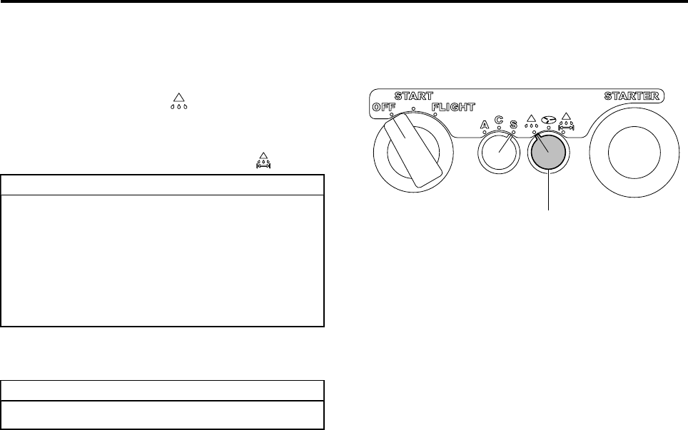
Selecting and Setting the Sprayer
1Turn the sprayer selector switch to select the
sprayer function.
•Turn the switch to “” to operate the liquid
sprayer.
•To use the speed-dependent feature of the
liquid sprayer, turn the switch to “”.
2Adjust the settings of the sprayer. For details,
see the operation manual for the sprayer.
●The sprayer selector switch cannot be
operated during a flight.
●The speed-dependent feature is enabled
only when the GPS signal reception is
good, regardless of the position of the
GPS control switch on the flight transmit-
ter.
Currently, the granular sprayer is not exported.
TIP
TIP
Sprayer Selector Switch
RMAX.book Page 3 Tuesday, January 17, 2012 3:06 PM
Pre-Flight Preparation and Inspection
4-4
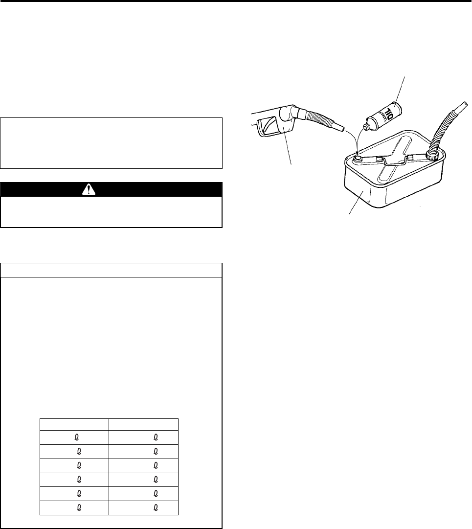
Preparing Fuel and Refueling
This product uses a fuel mixture consisting of regu-
lar gasoline and a specified type of 2-cycle engine
oil (hereafter referred to as “mixing oil”).
1Prepare fuel by mixing gasoline with oil. How-
ever, do not use gasoline that is blended with
ethanol.
Specified mixing oil:
Yamaha-specified oil
Mixing ratio:
Gasoline:mixing oil = 50:1
To prevent fire, mix fuel in a well-ventilated
area, away from any source of sparks or fire.
WARNING
Mixing Oil
Gasoline
Mix thoroughly
●Observe the correct mixing ratio of gaso-
line and oil, and mix them thoroughly
before use.
●Once the fuel is mixed, used it as soon as
possible. If the fuel is left unused for a
long period, the oil could separate. It is
best to prepare just enough fuel mixture to
be used in 1 day.
●To facilitate mixing, pour the oil into a con-
tainer before pouring in the gasoline.
●Volume of gasoline and oil:
TIP
Gasoline Oil
5 100 m
10 200 m
15 300 m
20 400 m
25 500 m
30 600 m
RMAX.book Page 4 Tuesday, January 17, 2012 3:06 PM
Pre-Flight Preparation and Inspection
4-5
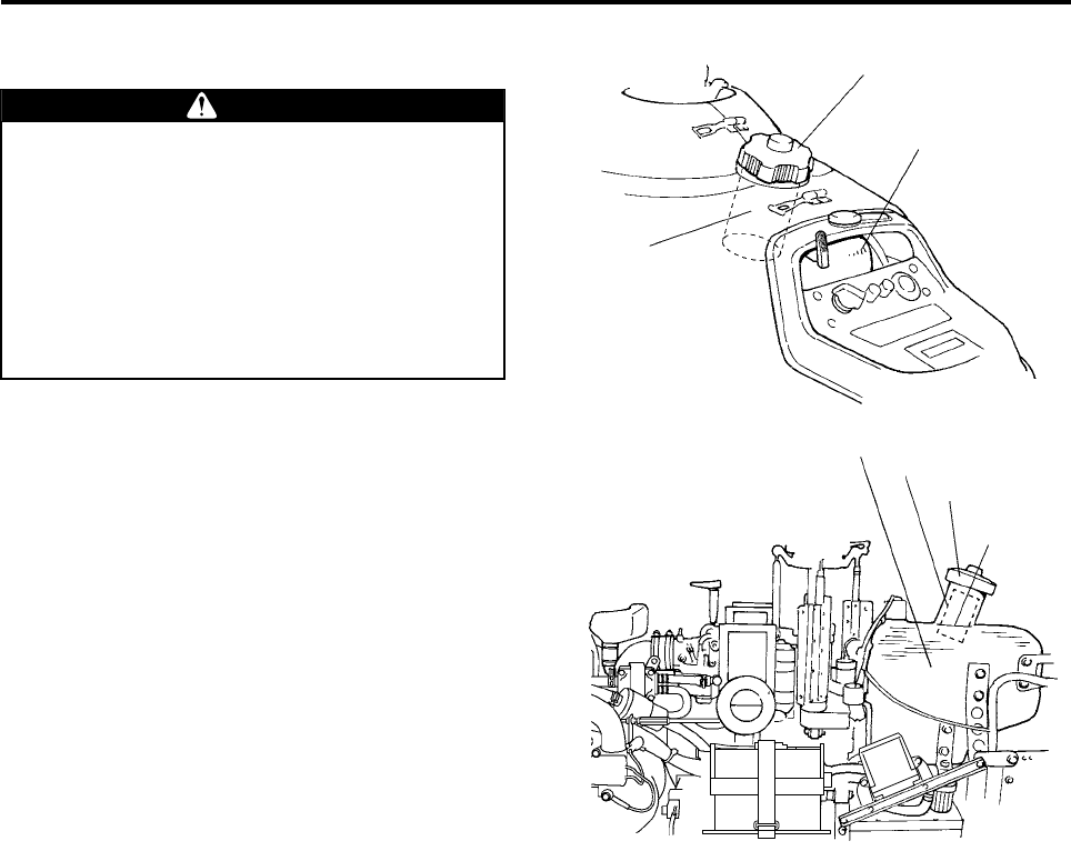
2Remove the fuel tank cap and refuel. Make sure
that a filter net is installed in the filler inlet.
●Stop the engine, and make sure there are
no sources of sparks or fire before refuel-
ing.
●Do not pour the fuel past the refueling limit
(up to the neck of the fuel tank). This is
dangerous, as the fuel may drip out during
a flight.
●After refueling, securely tighten the fuel
tank cap.
WARNING
Fuel Tank Cap
Fuel Tank
Filter Net
Fuel Tank Cap
Fuel TankFilter Net
Fuel Tank
Neck
RMAX.book Page 5 Tuesday, January 17, 2012 3:06 PM
Pre-Flight Preparation and Inspection
4-6
Transporting Procedure
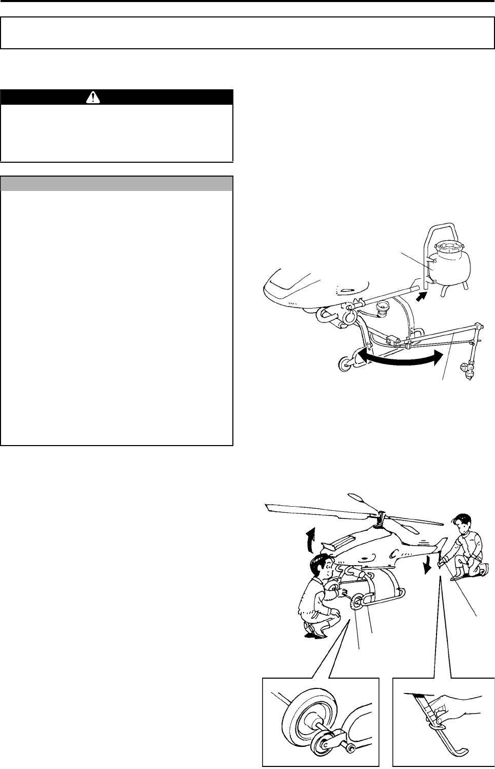
Installing and Removing Transport Wheels (sold separately)
To transport the helicopter by rolling it on the
ground, transport wheels must be attached to the
front of the runners. The installation (or removal) of
the wheels is done by 2 persons as follows:
1Use your hand to lower the stone guard to raise
the front end.
2Install (or remove) the transport wheels in the
recess located between the wheel and pipe in
the front of the runner.
Preparation on the Day of Flight
●To prevent burns, do not touch the muffler,
which could be very hot after a flight.
●Exercise caution to avoid poking your eyes
with the antenna or the like.
●Make sure to remove the chemical tank for
the sprayer. If a liquid sprayer is installed,
fold the boom before transporting the heli-
copter. See the operation manual of the
sprayer for details.
●Do not allow the main rotor blade to come
in contact with the ground or with any
objects in the area, as this could lead to
equipment damage.
●Do not hold the helicopter by the tail body,
tail cover, radiator, or antenna, as this
could lead to equipment damage.
●Make sure to turn OFF the main switch
before moving the helicopter. Otherwise,
the shocks from the movement will trans-
fer onto the sensors, and could cause the
helicopter to operate erroneously.
●To transport the helicopter by rolling it on
the ground, attach the transport wheels
(sold separately).
WARNING
NOTICE
Chemical Tank
Boom
Transport Wheel
Runner
Stone
Guard
RMAX.book Page 6 Tuesday, January 17, 2012 3:06 PM
Pre-Flight Preparation and Inspection
4-7
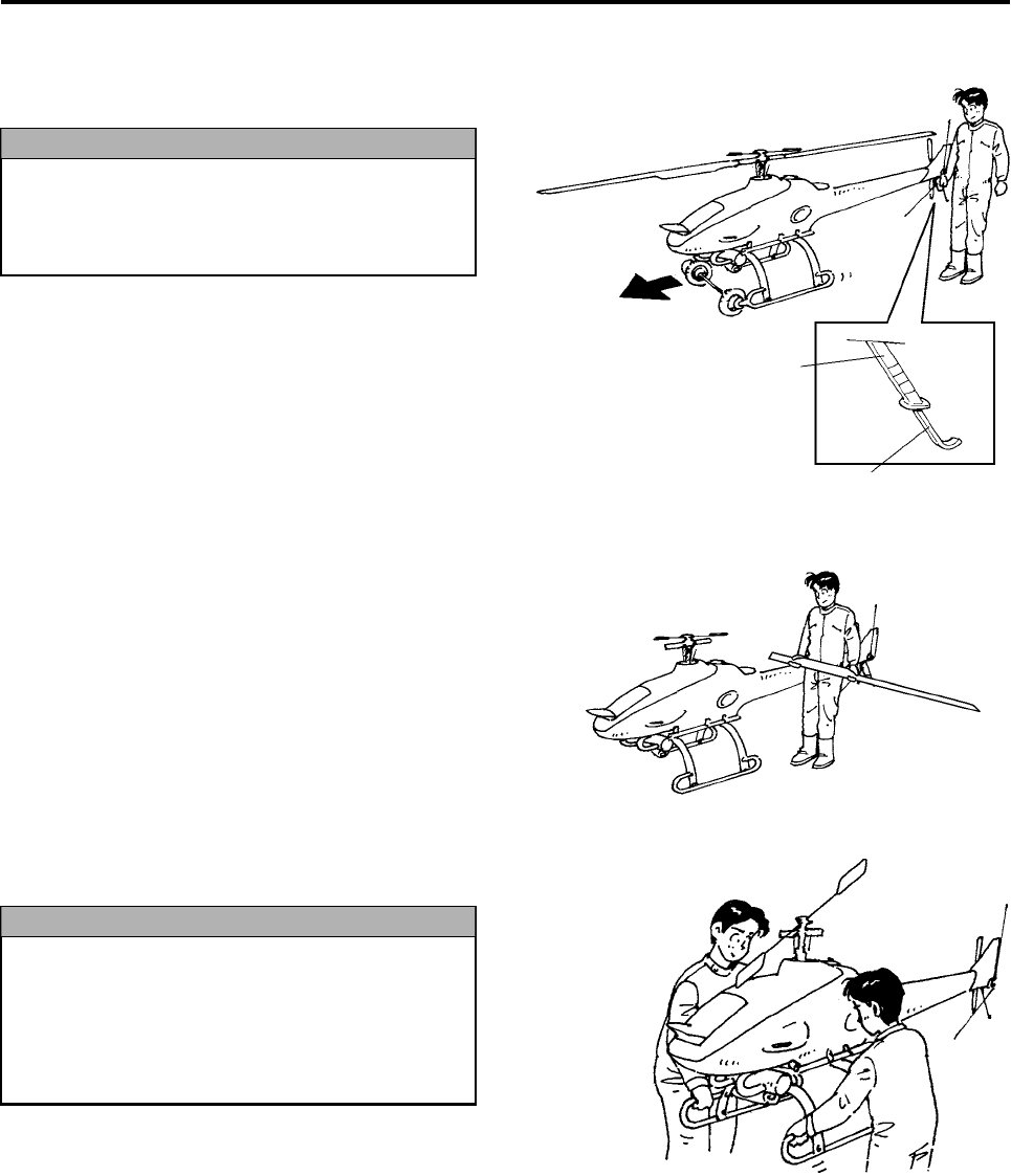
Moving Forward or Backward
Lift the tail by holding the grip handle of the stone
guard to move the helicopter forward (or backward).
Lifting and Lowering
1Remove the main rotor blades before loading the
helicopter on a truck bed. (See page 4-15.)
2Make sure that 2 persons or more lift the helicop-
ter, with each person holding the runner as
shown.
Make sure to hold the grip handle to move
the helicopter forward or backward. Do not
hold the tail cover or antenna, as this could
lead to equipment damage.
NOTICE
Grip Handle
Stone Guard
●Do not hold the helicopter by the exhaust
pipe of the muffler or the bar for attaching
the sprayer tank, as this could lead to
equipment damage.
●Transport carefully so as not to damage
the tail rotor.
NOTICE
RMAX.book Page 7 Tuesday, January 17, 2012 3:06 PM
Pre-Flight Preparation and Inspection
4-8
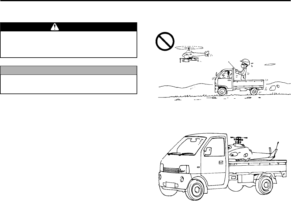
Transporting
1Use a truck to transport the helicopter.
Use a truck to transport the helicopter.
Do not attempt to fly the helicopter to another
site, as this could lead to an accident.
Make sure to remove the main rotor blades
before transporting the helicopter.
WARNING
NOTICE
RMAX.book Page 8 Tuesday, January 17, 2012 3:06 PM
Pre-Flight Preparation and Inspection
4-9
Radio Signal Interference Inspection
Because this product is operated by wireless radio
signals, the presence of radio signals with the same
or neighboring frequency in the vicinity will cause
the signals to cross, which will adversely affect the
control of the flight. Before a flight, use the supplied
radio signal monitor to check the radio frequencies
that are being transmitted in the area. (See the
operation manual of the radio signal monitor for its
operation procedure.)
During monitoring, make sure the power switch for
the flight transmitter is turned OFF.
●The unmanned helicopter for industrial
applications is operated by way of radio
signals. To prevent the helicopter from
going out of control due to unexpected
radio signal interference, pay careful
attention to any radio signal interference
before and during a flight.
●Cancel the flight if you detect the same fre-
quency that you will be using in the vicin-
ity. Otherwise, the radio signal interference
could render the helicopter out of control,
and could lead to serious accidents.
●Check for radio signal interference regu-
larly, including during breaks between
flights.
●Check for radio signal interference each
time you move to another area.
WARNING
RMAX.book Page 9 Tuesday, January 17, 2012 3:06 PM
Pre-Flight Preparation and Inspection
4-10
Payload Inspection
The actual payload of this helicopter varies consid-
erably according to its operating conditions
(weather, temperature, humidity, terrain, obstacles,
etc.) and flying methods, as well as the helicopter’s
individual differences.
Use the graph on the following page as a rule of
thumb for adjusting the payload with some margin
to ensure a safe aerial application flight.
Adjust the load to leave some margin in the
payload.
A takeoff with the maximum payload requires
maximum horsepower and careful flying
technique. An excess payload at this point
could lead to a serious accident. Make sure
to observe the following:
●Refer to the payload graph and check the
payload that meets your requirements.
●Check the payload margin by hovering.
●If the low speed warning flashes on the
YACS warning light, this means there is
not enough payload margin. Remove the
chemical tank on the right side before per-
forming the flight.
●If the position of the throttle stick immedi-
ately after takeoff is clearly high, this
means that there is not enough payload
margin. Remove the chemical tank on the
right side before performing the flight.
●If the engine is cold or when flying for the
first time after a periodic inspection, as a
guide, adjust the payload to about half of
the capacity.
●Contamination of the main rotor blades by
pollen, etc., will cause the payload capac-
ity to decrease. Clean it during breaks.
●If the cushion tape has a peel or a damage,
it can cause the payload capacity to
decrease. Cancel the flight and request a
repair by your dealer. (See page 4-22.)
WARNING
NOTICE
RMAX.book Page 10 Tuesday, January 17, 2012 3:06 PM
Pre-Flight Preparation and Inspection
4-11
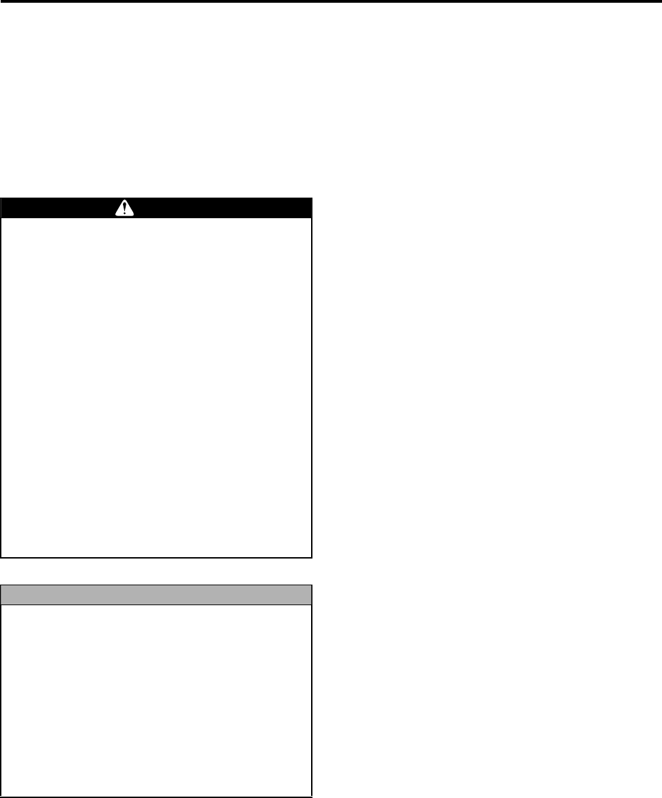
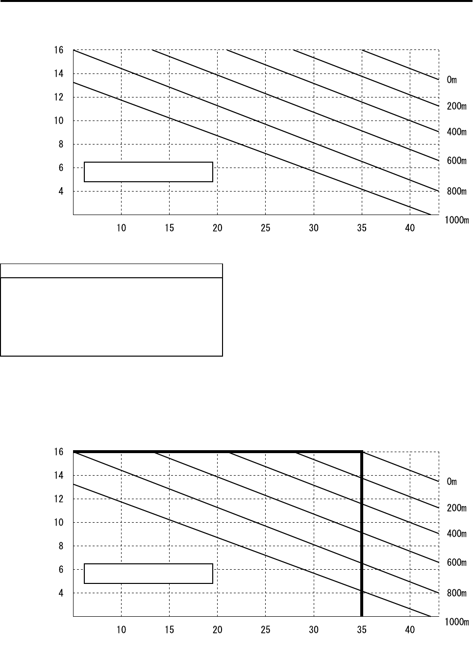
How to Read the Payload Graph
(Example)
Reference value for payload in an agricultural field at temperature 35 °C, altitude 0 m: 16 kg
Temperature(˚C)
Altitude
Chemical Load Capacity (kg)
Maximum Chemical Load Capacity:
16 kg
This graph is not intended to guarantee the
payload performance of the helicopter. The
actual payload values could differ from this
graph, depending on the helicopter’s condi-
tions, operation conditions, humidity, oxygen
concentration, and other factors.
TIP
Temperature(˚C)
Altitude
Chemical Load Capacity (kg)
Maximum Chemical Load Capacity:
16kg
RMAX.book Page 11 Tuesday, January 17, 2012 3:06 PM
Pre-Flight Preparation and Inspection
4-12
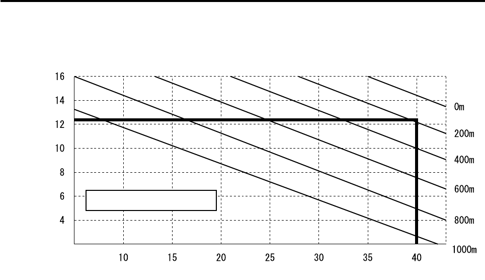
(Example)
Reference value for payload in an agricultural field at temperature 40 °C, altitude 200 m: Approx. 12 kg
Temperature(˚C)
Altitude
Chemical Load Capacity (kg)
Maximum Chemical Load Capacity:
12kg
RMAX.book Page 12 Tuesday, January 17, 2012 3:06 PM
Pre-Flight Preparation and Inspection
4-13
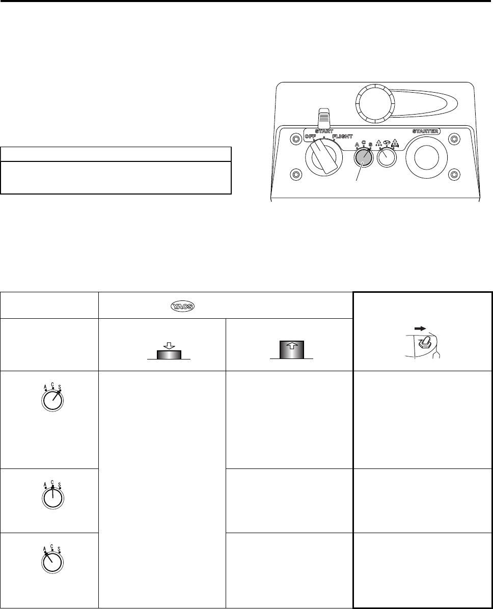
Selecting the Flight Mode
Before a flight, turn the “flight mode selector switch”
to the flight mode that you wish to use.
•To use the A or AG mode, turn the switch to
“A”.
•To use the C or CG mode, turn the switch to
“C”.
•To use the S or SG mode, turn the switch to
“S”.
Do not operate the flight mode selector
switch during a flight.
TIP
Flight Mode Selector Switch
YACS Control Switch YACS control switch ON + GPS
control switch ON
Flight Mode Selector
Switch
“OFF”“ON”
S Manual Mode
Control support is unavail-
able in this mode. Use this
in emergencies only.
S Mode
Compared to the C mode,
the S mode provides greater
control support to ensure
safety of the helicopter.
SG Mode
Move the stick only as much as
you wish to fly, and release it to
stop the movement. Thus, this
mode allows you to operate
with peace of mind.
It can be used only for flying
forward or backward.
C C Mode
This standard flight mode
uses the YACS control to
balance the helicopter’s sta-
bility and flying comfort.
CG Mode
In addition to the flying charac-
teristics of the C mode, this
mode provides hovering stabil-
ity through GPS control.
AA Mode
This mode has less control
support than the C mode,
allowing the operator to
assume more control.
AG Mode
In addition to the flying charac-
teristics of the A mode, this
mode provides hovering stabil-
ity that is lower than the CG
mode.
OFF ON
Push Release
RMAX.book Page 13 Tuesday, January 17, 2012 3:06 PM
Pre-Flight Preparation and Inspection
4-14
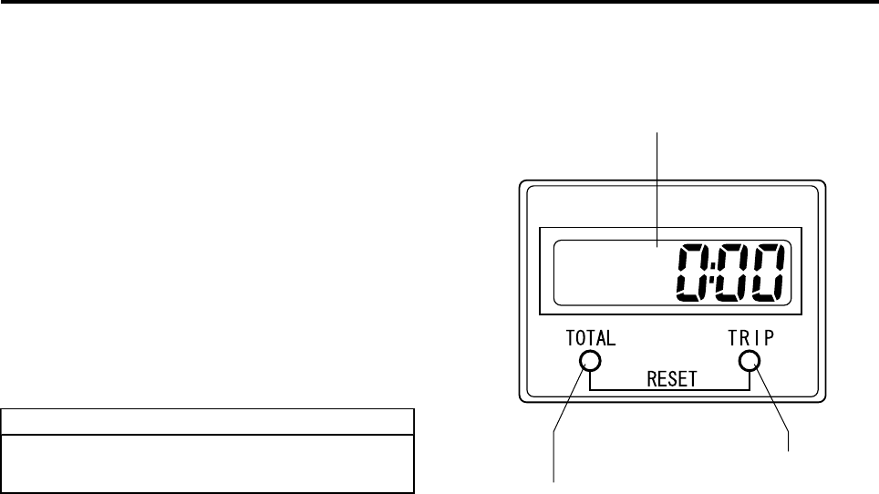
Displaying and Recording Flight Hours
The hour meter on the control panel displays and
records the engine’s flight hours.
1TOTAL: Displaying the total flight hours
Press the TOTAL key to display the helicopter’s
total flight hours, which can serve as guidelines
for changing oil or performing periodic inspec-
tions.
2TRIP: Displaying the day’s flight hours
Press the TRIP key to display the logged flight
hours since the last time it was reset.
3TRIP: Resetting the day’s flight hours
After the number of TRIP hours appears on the
display, simultaneously press the TOTAL and
TRIP keys to reset the number of hours to “0”.
Make sure to enter the flight hours in the
flight inspection log.
TIP
LCD Display
TOTAL Key
(total flight hours)
TRIP Key
(short-term cumula-
tive hours)
RMAX.book Page 14 Tuesday, January 17, 2012 3:06 PM
Pre-Flight Preparation and Inspection
4-15
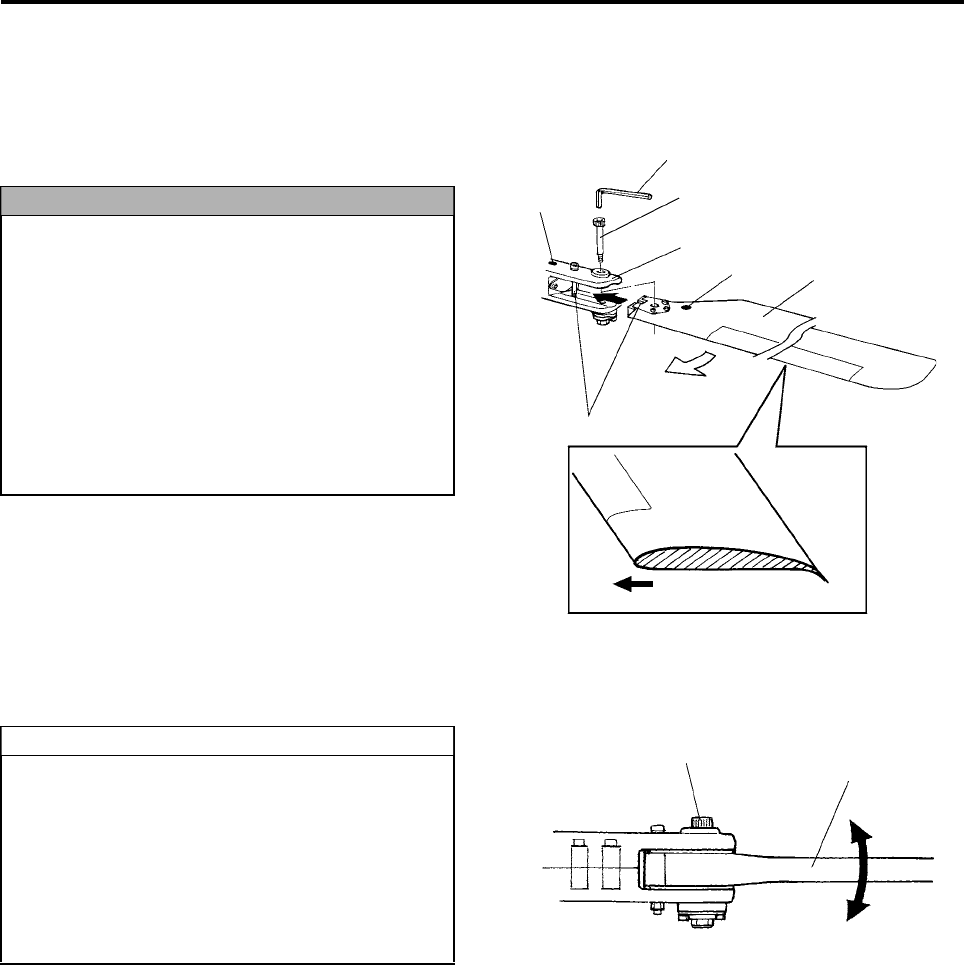
Installing and Removing Main Rotor Blades
How to Install Main Rotor Blades
1Insert the main rotor blades into the main blade
holder.
2Use an 8mm hex wrench to tighten the retaining
bolts.
Check the tightening of the retaining bolts as fol-
lows:
●Tighten each retaining bolt until it comes to a
stop. Then, back it out between 45° to 90°.
Make sure it is not tightened or loosened
excessively, which could cause vibrations.
●Check that the main rotor blades move
smoothly by moving them slightly in the direc-
tion of rotation. They are designed to stop by
coming in contact with rubber stops if they are
moved extensively.
How to Remove Main Rotor Blades
Remove the main rotor blades in reverse order of
installation.
●There are two main rotor blades: right and
left. Install them by matching the color of
the mark of the respective main rotor blade
to the blade holder.
●Each main rotor blade has a top and bot-
tom. Install it so that its leading edge is
oriented in the direction of rotation as
shown in the cross section diagram.
●Check that the main rotor blades are free
of debris such as pollen or bugs before
installing them.
NOTICE
Hex Wrench
Retaining Bolt
Main Rotor Blade
Mark
Align groove to bolt
Mark
Cross Section Diagram
Direction of rotation
Blade Holder
Direction of rotation
●The main rotor blades are properly
installed if their retaining bolts do not
wobble when the blades are moved verti-
cally, and if they move smoothly in the
direction of rotation when a small force is
applied.
●Tighten both rotor blades to approximately
the same amount of torque.
TIP Retaining Bolt Main Rotor Blade
No wobble in this direction
RMAX.book Page 15 Tuesday, January 17, 2012 3:06 PM
Pre-Flight Preparation and Inspection
4-16
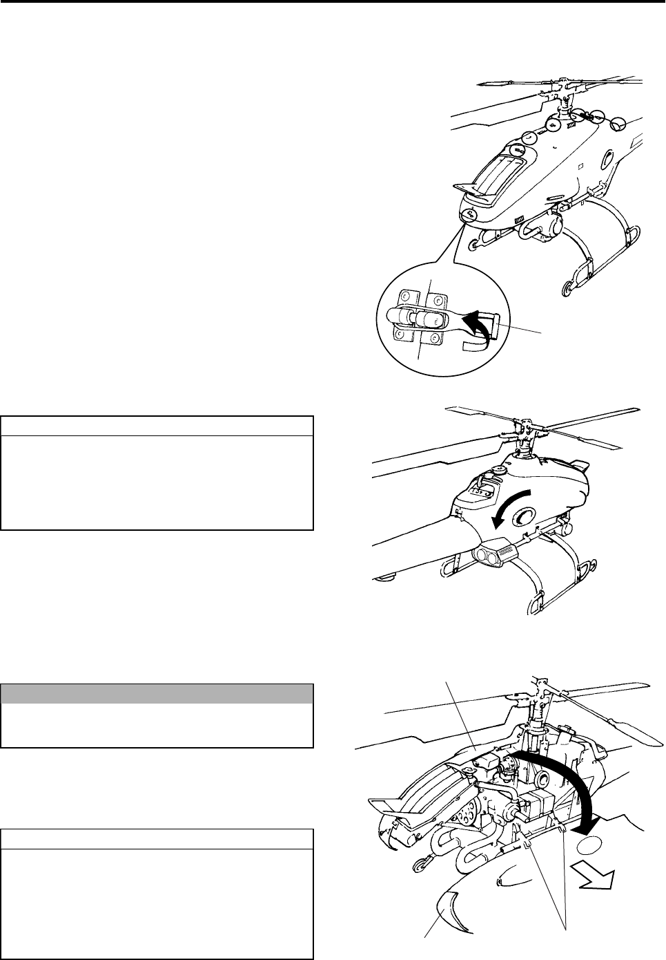
Installing and Removing Side Covers
How to Remove Side Covers
1Undo the 7 rubber hooks that are located along
the top of the helicopter by lifting them towards
the left.
2Open the side covers from side to side.
3To completely remove a side cover after it is
open, hold the retaining hooks to pull the side
cover sideways and remove it from the frame.
How to Reinstall Side Covers
Reinstall the side covers in reverse order of
removal.
Rubber hooks
●Tilt the sprayer antenna towards the rear
before opening the right side cover.
●Make sure the side cover does not get
caught on the starter lever or the fuel tank
cap.
TIP
Do not hold a side cover during removal, as
this could lead to damage.
●Place the right and left side covers and
lock them in place by engaging the 7 rub-
ber hooks.
●After the right side cover is closed, return
the sprayer antenna to its original posi-
tion.
NOTICE
TIP
Side Cover (right)
Side Cover (left) Retaining Hooks
RMAX.book Page 16 Tuesday, January 17, 2012 3:06 PM
Pre-Flight Preparation and Inspection
4-17
To ensure safe and efficient operation of the heli-
copter, make sure the operator performs the pre-
flight inspection. In addition, enter the results in the
flight inspection log.
Pre-flight Inspection
To prevent injury, make sure the engine is
stopped before performing an inspection.
WARNING
Inspection Point Inspection Items Flight
Pre Post
1Transmitter • Battery Level
• Operation
• Antenna installation
2 Fuel • Level
• Leakage
3 Coolant, oil • Level
• Leakage
4 Rotor blades • Dirtiness, damage
• Movement
Air cleaner • Dirtiness
5Servo, linkage
(rudder, throttle) • Operation
• Wobble
6 Self monitor • States of lighting
7Radio signal
distance test • Radio signal reach
8 Tail rotor drive belt
• Tension
• Abnormal noise
• Wear, damage
• Refuel
9 GPS system • States of lighting
Antenna • Installation state
• Rust
RMAX.book Page 17 Tuesday, January 17, 2012 3:06 PM
Pre-Flight Preparation and Inspection
4-18
Transmitter Inspection
Inspect the flight transmitter battery level, opera-
tion, and antenna conditions.
1Battery Level Inspection
With the main switch on the helicopter turned
OFF, turn the power to the transmitter ON to per-
form the following inspections:
●Check that the output light is ON.
●Listen to the buzzer for the number of beeps
that indicates the battery level.
●Check that the battery monitor light is not illu-
minated.
This light operates in unison with the number
of beeps of the buzzer. It flashes when the
battery level is low. Afterwards, it will illumi-
nate to warn the operator. This condition indi-
cates that the battery level is almost empty,
and it should be replaced with a fully charged
battery.
2Transmitter Operation Inspection
When the power of the transmitter is turned ON,
apart from the buzzer sounding to indicate the
battery level, if the buzzer beeps in a 3-3-7 pat-
tern or the output light does not illuminate, the
transmitter may be malfunctioning. If this occurs,
cancel the flight and request a repair by your
dealer.
3Antenna Inspection
Inspect the antenna to make sure it is not loose
in the area where it is mounted to the transmitter.
Extend the antenna and inspect it for looseness
or rust.
If the antenna is loose in the area where it is
mounted, tighten the antenna.
If the antenna is loose or rusted, replace the
antenna.
If the transmitter has a malfunction or the
battery level is low, the transmitter will be
unable to send radio signals during a flight.
Beep beep beep beep (4 times) Fully
charged
Beep beep beep (3 times)
Beep beep (2 times) Requires
charging.
Beep (1 time) Inoperable
unless
charged.
WARNING
Battery Monitor Light
Output Light
Mounted area of antenna
Tighten
RMAX.book Page 18 Tuesday, January 17, 2012 3:06 PM
Pre-Flight Preparation and Inspection
4-19
Fuel Inspection
Inspect the fuel level and check for any leaks.
Before performing this inspection, turn OFF both
the main switch for the helicopter and the power
switch for the transmitter.
1Fuel Level
Visually check the fuel level in the fuel tank. Dur-
ing refueling, do not remove the filter net.
2Fuel Leak
Inspect the following areas to make sure there
are no fuel leaks:
•Fuel Tank
•Fuel Tank Cap
•Fuel Filter
•Fuel Pump
•Fuel Lines
If you discover a fuel leak, immediately cancel the
flight and request a repair by your dealer.
Fuel Tank
Fuel Tank Cap
Filter
Net
Fuel Pump
Fuel Filter
●To prevent fires, stop the engine and keep
the helicopter away from any source of
sparks or fire during refueling.
●Fuel leakage could lead to a fire.
WARNING
Fuel Filter
Fuel Pipe
RMAX.book Page 19 Tuesday, January 17, 2012 3:06 PM
Pre-Flight Preparation and Inspection
4-20
Coolant and Oil Inspections
Inspect the coolant level and check for any coolant
or oil leakage.
Before performing this inspection, turn OFF both
the main switch for the helicopter and the power
switch for the transmitter.
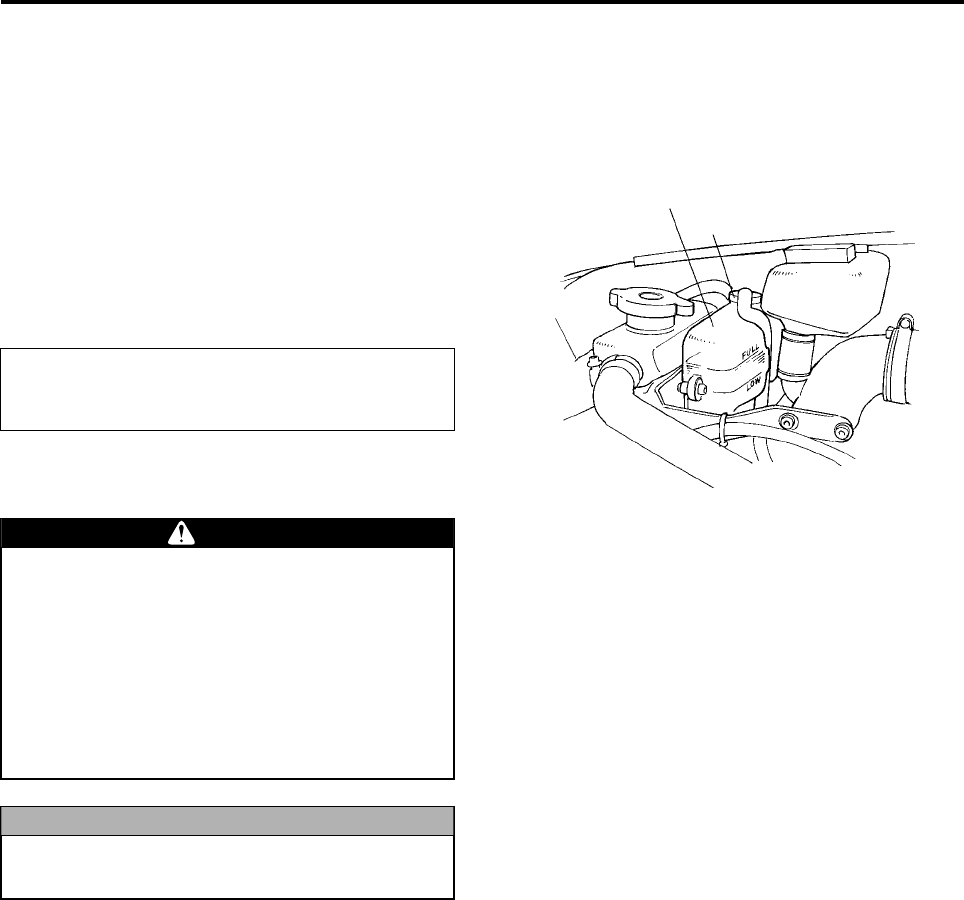
1Recovery Tank
Inspect the tank cap for any coolant leakage.
Also, check the coolant level.
The standard coolant level is between the FULL
and LOW marks indicated on the recovery tank.
Coolant Preparation
Coolant: Dealer-specified coolant
Mixing ratio: Dealer-specified ratio
Recovery Tank
Cap
Coolant is toxic, therefore use caution when
handling it.
●If it enters your eye, flush it thoroughly
with water, and seek medical attention.
●If it contacts your skin or clothing,
promptly rinse with water and wash with
soap water.
●If swallowed, induce vomiting and seek
medical attention.
Use tap water, instead of well water or natural
water that contains sodium.
WARNING
NOTICE
RMAX.book Page 20 Tuesday, January 17, 2012 3:06 PM
Pre-Flight Preparation and Inspection
4-21
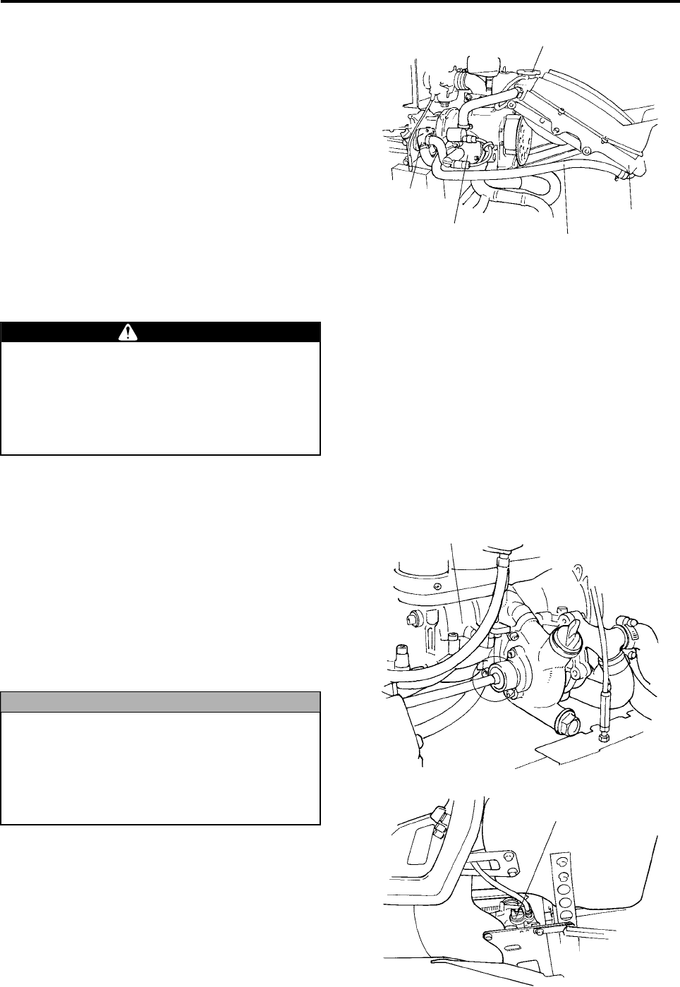
2Water Pump
Inspect the mating surface of the housing cover,
rubber hoses, and rubber hose connections for
any coolant leakage.
During the initial stage of helicopter operation,
the water pump may leak a small amount of
coolant (10 to 20cc could leak from the drain
hole at the bottom of the water pump, onto the
absorbent pad provided on the frame). This nor-
mal condition occurs while the internal seal is
being broken in. It will eventually stop with con-
tinued operation of the helicopter.
3Radiator
Inspect the radiator cap and the rubber hose
connections for any coolant leakage.
4Engine
Inspect the mating surface of the cylinder body
and the oil seal for any oil leakage, and the cylin-
der head for any coolant leakage.
5Transmission and Intermediate Transmission
Inspect the mating surface of the transmission
case and the oil seal for any oil leakage.
A slight stain of coolant or oil does not indicate an
abnormal condition. However, if the coolant or oil is
leaking in a dripping manner, cancel the flight and
request a repair by your dealer.
Radiator Cap
Water Pump
Cylinder Head Hose
Radiator
When necessary, remove the radiator cap
only after the engine has cooled down. If the
radiator cap is removed immediately after the
engine has been stopped, when the coolant
is extremely hot, the scalding liquid could
shoot out and cause burns.
WARNING
●Coolant leakage will adversely affect the
cooling performance of the helicopter and
cause it to overheat.
●Oil leakage will reduce the internal lubrica-
tion of the transmission and damage the
gears and bearings.
NOTICE
Transmission Case
Intermediate Transmission
RMAX.book Page 21 Tuesday, January 17, 2012 3:06 PM
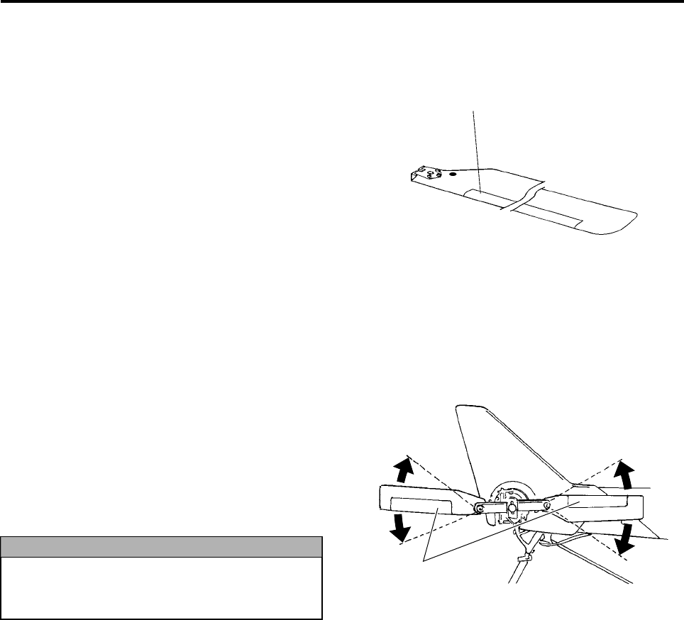
Pre-Flight Preparation and Inspection
4-22
Rotor Blade Inspection
Inspect the rotor blades for damage, dirtiness, and
movement.
Before performing this inspection, turn OFF both
the main switch for the helicopter and the power
switch for the transmitter.
1Main Rotor Blades
●Inspect the main rotor blades’ surfaces for
dirtiness, fissures, cracks, or chips.
●Inspect the cushion tape for peeling or dam-
age.
●After the main rotor blades have been
installed, inspect them to make sure they
rotate smoothly in both directions. (See page
4-15.)
2Tail Rotor Blades
●Inspect the tail rotor blades’ surfaces for dirti-
ness, fissures, cracks, or chips.
●Inspect the cushion tape for peeling or dam-
age.
●Inspect the tail rotor blades to make sure they
rotate smoothly in both directions.
If a rotor blade’s surface is dirty, use household
detergent on a soft cloth, wring the cloth, and use it
to wipe the rotor blade’s surface.
If the rotor blade is damaged, cancel the flight and
request a repair by your dealer.
Cushion Tape
If a main or tail rotor blade does not move
smoothly or is damaged, it could generate
noise or vibration.
NOTICE
Cushion Tape
RMAX.book Page 22 Tuesday, January 17, 2012 3:06 PM
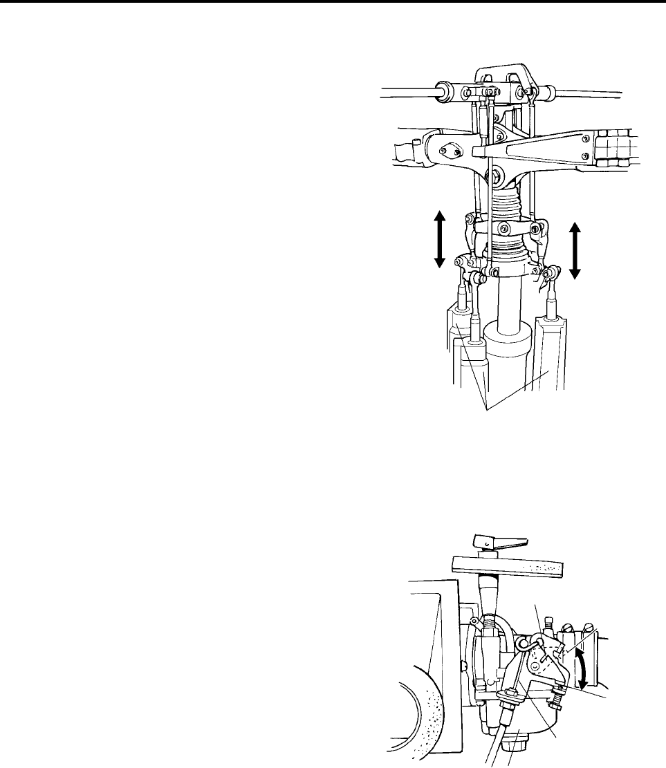
Pre-Flight Preparation and Inspection
4-23
Servo and Linkage Inspection
Inspect the servos and linkages for proper opera-
tion.
Before performing this inspection, turn the power
switch for the transmitter to ON and the main switch
for the helicopter to START.
1Slide Servo and Linkage Inspection
Inspect the servos and linkages to make sure
they smoothly follow the movements of the throt-
tle, elevator, and aileron sticks when the sticks
are moved slowly up-and-down and side-to-side.
Also, make sure the linkages do not wobble.
2Throttle Inspection
●Throttle fully open and fully closed
•Move the throttle stick to its maximum posi-
tion and check that the throttle valve in the
carburetor moves to the fully open position.
•Move the throttle stick to the slowest posi-
tion and check that the throttle valve in the
carburetor moves to the fully closed posi-
tion. Keep the throttle trim lever in the lowest
position.
●Throttle cable movement and play
•Slowly move the throttle stick up and down
and check that the throttle cable moves
smoothly without catching.
•Check that the throttle cable has a slight
play when the throttle valve is in the fully
closed position.
Slide Servo
Throttle Valve Fully Open
(maximum
throttle)
Fully Closed
(slowest
throttle)
Throttle Cable
Carburetor
RMAX.book Page 23 Tuesday, January 17, 2012 3:06 PM
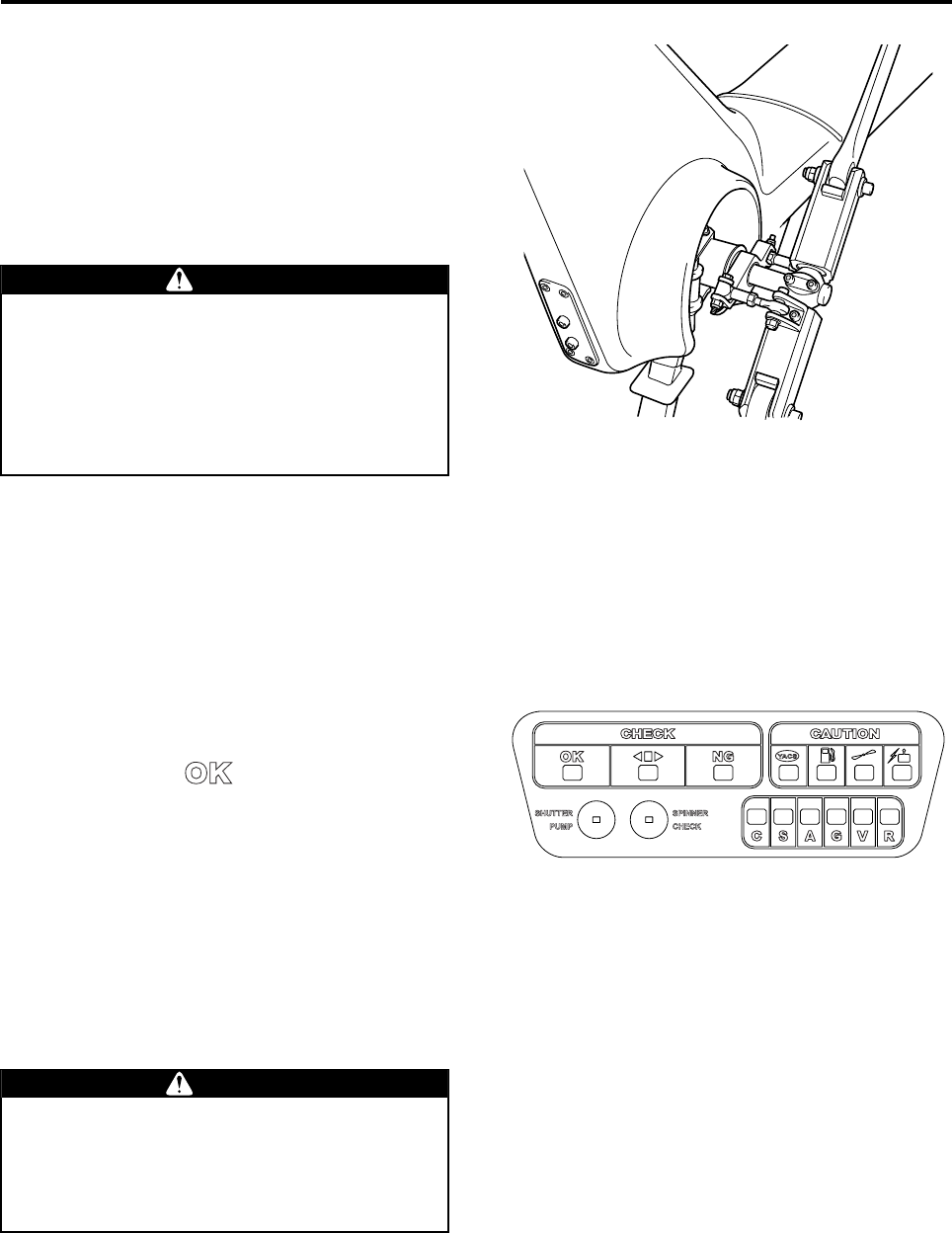
Pre-Flight Preparation and Inspection
4-24
3Rudder Servo and Linkage Inspection
Move the throttle and the rudder sticks up-and-
down and side-to-side and check that the servo
and the linkage smoothly follow the movement of
the sticks. Also, check that the linkage does not
wobble.
If any of the servos operate abnormally or the link-
ages wobble, cancel the flight and request a repair
by your dealer.
Self Monitor Inspection
Inspect the illumination of the indicator lights on the
self monitor for proper operation.
1With the power for the transmitter turned ON,
turn the main switch on the helicopter to START,
and check that all lights illuminate for 2 seconds.
2After the YACS control has completed configura-
tion, check the illumination of the indicator lights.
•Check that the “” flight indicator light illu-
minates.
•Check that the check point indicator lights do
not illuminate.
•Check that the malfunction area indicator lights
do not illuminate.
If there is a problem with the illumination of the
flight indicators or check point indicators, take the
appropriate actions in accordance with the table on
page 3-5.
If a malfunction area indicator light illuminates, can-
cel the flight and request a repair by your dealer.
●If the servos operate abnormally or the
linkages wobble, they could adversely
affect the control of the helicopter.
●If the throttle operates abnormally, it could
adversely affect engine control, which
could cause the helicopter to go out of
control.
WARNING
Take the appropriate actions in accordance
with the indicator lights. By ignoring the
lights and continuing to fly, you will lose con-
trol of the helicopter and cause a serious
accident.
WARNING
RMAX.book Page 24 Tuesday, January 17, 2012 3:06 PM
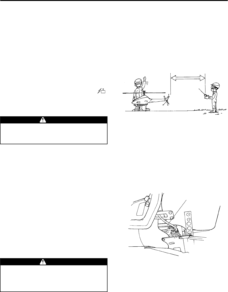
Pre-Flight Preparation and Inspection
4-25
Radio Signal Distance Test
Conduct a radio signal distance test to inspect that
the system is operating normally.
Before performing this inspection, turn the power
switch for the transmitter to ON and the main switch
for the helicopter to START.
1Retract the antenna of the transmitter to its
shortest length.
2Have one person operate the transmitter while
another person checks the helicopter, with an
approximate distance of 50 m between the two.
3Operate the transmitter and check that the ser-
vos operate accordingly. Make sure the “”
light of the check point indicator is not lit.
If the reach of the radio signals is less than 50 m,
cancel the flight and request your dealer for repair.
Tail Rotor Drive Belt Inspection
Inspect the condition of the tail rotor drive belt and
apply lubricant to the belt.
Before performing this inspection, turn OFF both
the main switch for the helicopter and the power
switch for the transmitter.
1Inspect for looseness in the tension of the belt.
2Check that the belt is free of damage, abnormal
wear, and noise during operation.
3Apply a sufficient amount of the dealer-specified
lubricant to the belt.
If there is a problem with the belt, cancel the flight
and request your dealer for repair.
If the reach of the radio signals is too short,
radio signal interference could render the
helicopter out of control during flight.
WARNING
50m
If there is a problem with the tail rotor belt, it
could adversely affect the actuation of the tail
rotor, which could cause the helicopter to go
out of control.
WARNING
Tail Rotor Drive Belt
RMAX.book Page 25 Tuesday, January 17, 2012 3:06 PM

Pre-Flight Preparation and Inspection
4-26
GPS System Inspection
Inspect to make sure the GPS system is operating
normally.
Before performing this inspection, turn the power
switch for the transmitter to ON and the main switch
for the helicopter to START.
Inspect the illumination of the GPS indicator light by
referring to the table on 3-9 - 3-10.
If the light flashes for 3 minutes or more after the
YACS control has completed configuration, this
means the reception of the GPS signals may be
poor. In this case, operate the flight only under
YACS control. If the GPS indicator light does nei-
ther illuminate nor flash, the GPS system may have
failed. In this case, request your dealer for repair.
If the power for the flight transmitter is OFF, the light
will stop illuminating in 1 minute, but this condition
is normal. Turn the power for the flight transmitter
ON.
GPS
Indicator Light
YACS
Warning Light
RMAX.book Page 26 Tuesday, January 17, 2012 3:06 PM

Pre-Flight Preparation and Inspection
4-27
RMAX.book Page 27 Tuesday, January 17, 2012 3:06 PM

Flying Procedure
Flying Precautions ..................................................................... 5-1
Engine Starting .......................................................................... 5-3
Pre-start Checks .................................................................................5-3
Engine Starting ...................................................................................5-5
Takeoff Precautions and Checks ............................................. 5-8
Takeoff Procedure ..............................................................................5-8
Post-Takeoff Checks ..........................................................................5-9
General Aerial Application Pattern .................................................5-10
Landing and Engine Stopping ................................................ 5-11
Landing ..............................................................................................5-11
Engine Stopping ...............................................................................5-11
Precautions for First Flight After Periodic Inspection ......... 5-13
Fuel ....................................................................................................5-13
Onboard Battery ...............................................................................5-13
First Flight Procedure ......................................................................5-13
5
RMAX.book Page 1 Tuesday, January 17, 2012 3:06 PM

5-1
Flying Procedure
This section summarizes the precautions for a series of operations from takeoff to landing, as well as for han-
dling the helicopter. Some of the contents may overlap the instructions given at the Academy.
Preparation - Takeoff
Takeoff - Hovering
Flying Precautions
Never approach (or allow others to approach) within 20 m of the helicopter until the main rotor has
come to a complete stop and the engine has stopped. Entering within 20 m of the helicopter could
cause a serious accident.
DANGER
●Do not take off or land on sloping terrain, as this could cause the helicopter to overturn, or
adversely affect its control. As a rule, the helicopter should take off and land on a level surface.
Make sure to select an appropriate location before commencing a flight.
●Select areas that are appropriate for takeoffs and landings, as described below. Failure to select
an appropriate area could lead to an accident.
• Select flat farm roads or vacant lots with minimal foot or vehicle traffic.
• Check that there are no obstacles in the vicinity.
• Check that there are no objects that could get picked up by the wind (such as mowed grass, plastic
tape, plastic bags, etc.).
WARNING
●Do not operate the throttle stick while the outer YACS warning light is flashing. The engine will
stop if the throttle stick is moved far up.
●Do not operate the rudder excessively right before a takeoff, as this will cause the helicopter to
move abruptly in the direction of the rudder after the takeoff.
●During takeoff, do not turn ON the GPS control switch, as this could cause the helicopter to not
ascend straight up.
TIP
●Do not operate the sticks abruptly as this could cause the helicopter to lose balance and lead to
an accident.
●For the first flight of the day, allow the helicopter to hover for 1 or 2 minutes while the engine
warms up, and check that the helicopter operates normally. Failure to do so will prevent the
engine from attaining the proper power, which could lead to an accident.
WARNING
After takeoff, turn the GPS control switch ON while hovering. If this switch was ON during takeoff,
turn it OFF while hovering, and turn it back ON.
TIP
Chap5.fm Page 1 Wednesday, January 18, 2012 10:17 AM
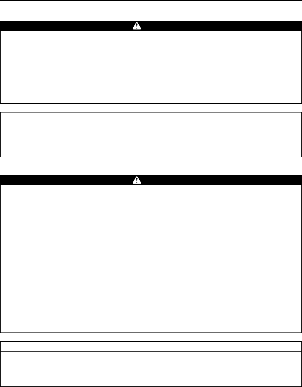
Flying Procedure
5-2
Hovering - Flying
Flying - Landing
●Adjust the load to leave some margin in the payload. A takeoff with the maximum payload
requires maximum horsepower and careful flying technique. An excess payload at this point
could lead to a serious accident. Therefore, hover the helicopter to check that there is an ample
margin in payload before continuing with the flight.
●Keep the distance between the operator and the helicopter within 150 m, and the flight altitude at
3 - 4 m (from the ground or from the crop). If the distance is any greater, it will prevent the opera-
tor from monitoring the posture of the helicopter and adversely affect the signal reception condi-
tions. For safety, further shorten the distance if there are any obstacles in the area. Failure to fly
the helicopter within the maximum distance limit could lead to an accident.
WARNING
●Do not turn continuously while banking in one direction for more than 10 seconds, as this will
cause the helicopter to drift as if the trim has shifted.
●Do not turn in the SG mode. Because the operation method for this mode is different from other
modes, the helicopter could make an unexpected movement.
TIP
●Do not lower the throttle stick to the slowest position during a flight, as this could disrupt the
engine speed control and cause the helicopter to descend abruptly.
●If the YACS warning light or the GPS indicator light shows an abnormal condition, the helicopter
exhibits irregular behavior, or an unusual symptom occurs (such as vibration, sound, coolant
leakage, or foul odor), immediately land the helicopter in a safe area. Continuing with the flight in
this state could lead to an accident.
●Do not press the Engine Stop switch during a flight, as this will stop the engine and cause the
helicopter to descend abruptly. However, to force the helicopter to land in case of an emergency,
press the switch after making sure that it is safe to do so.
●Abort the flight or aerial application if poor weather conditions exist as described below. Failure
to do so could pose operation difficulties, which could lead to an accident. In addition, it could
adversely affect the application and the effectiveness of the sprayed chemicals.
• Wind velocity in excess of 3 m per second at a height of 1.5 m above the ground.
• Rain, fog, or lightning in the close vicinity.
●Observe the following until the engine has come to a complete stop after landing:
• Do not turn OFF the power of the flight transmitter.
• Do not take remove or replace the battery in the transmitter.
Failure to observe these precautions will trip the failsafe device (speed control turns ON auto-
matically), which will cause the engine to accelerate suddenly.
WARNING
During a takeoff or landing, if the engine speed does not decrease even if the throttle stick is low-
ered to the slowest position, calmly turn the YACS control switch OFF. This symptom could occur if
a takeoff operation is aborted or if there are a considerable number of landing shocks when the
helicopter lands.
TIP
Chap5.fm Page 2 Wednesday, January 18, 2012 10:17 AM
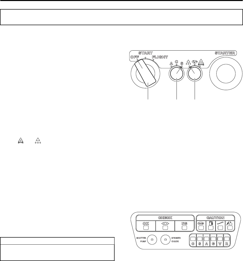
Flying Procedure
5-3
Pre-start Checks
1Check that the flight mode selector switch on the
helicopter is set to the position that you have
selected.
•To use the A or AG mode, turn the switch to
“A”.
•To use the C or CG mode, turn the switch to
“C”.
•To use the S or SG mode, turn the switch to
“S”.
See page 4-13 for a detailed description of the flight
modes.
2Check that the sprayer selector switch is set to
the position of the sprayer that you will be using.
•When using the liquid sprayer, turn the switch
to “” or “”.
3Extend the antenna of the transmitter and turn
the power switch ON.
•Check the battery level (the buzzer should
beep a minimum of 3 times).
•Check that the YACS control switch is ON and
the GPS control switch is OFF.
4Turn the main switch on the helicopter to START.
•Check that all the lights on the self monitor illu-
minate for 2 seconds.
•Check all of the lights of the temperature sen-
sor monitoring LED.
Engine Starting
41
2
Currently, the granular sprayer is not
exported.
TIP
RMAX.book Page 3 Tuesday, January 17, 2012 3:06 PM
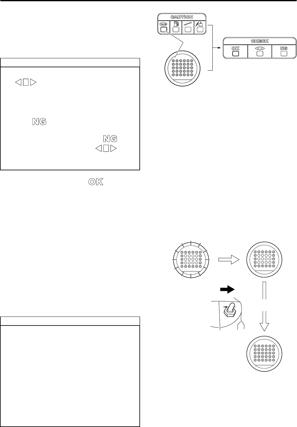
Flying Procedure
5-4
5The SETTING light on the check point indicator
flashes approximately 3 times (for 10 seconds),
and the system performs YACS control configu-
ration and self checks.
Check that all the red YACS warning lights on the
back of the helicopter illuminate during configuration.
If there are no problems, the “” light of the
flight indicator will illuminate, indicating that the
YACS control configuration has completed.
6After the YACS control configuration has com-
pleted and the YACS warning light has turned
OFF, the outer lights of the GPS indicator will
flash and the GPS control configuration will start.
•The outer GPS indicator lights will flash while
GPS control is being configured.
•The outer GPS indicator lights will change from
flashing to constant illumination when the GPS
control configuration has completed (which
take about 3 minutes).
•After the lights illuminate, turn ON the GPS
control switch on the transmitter. Then, check
that all the GPS indicator lights illuminate.
•After checking that all lights illuminate, turn
OFF the GPS control switch.
●Do not move the helicopter while the
“” light is flashing.
●Configuring the YACS control with the heli-
copter tilted could cause errors. Therefore,
it is recommended to select a flat area for
this purpose.
●If the “” light illuminates on the flight
indicator, first turn the main switch OFF;
then, turn it to START. If the “” light
illuminates again or if the “” light
continues to flash, contact your dealer for
repair.
TIP
5
●Step 5 completes the pre-start checks if
you will not be using GPS control or if you
will be using it later during the flight.
●The length of time it takes to complete the
GPS control configuration varies accord-
ing to GPS signal reception. If it takes too
long (the lights do not illuminate after 3
minutes), you will not be able to use GPS
control in the AG, CG, or SG mode. Oper-
ate the helicopter under YACS control until
the signal reception improves, which will
be indicated by the illumination of the
outer lights.
TIP
OFF ON
Outer lights flashing
(configuration in progress)
(After approximately
3 minutes)
Outer lights illuminating
(configuration complete)
GPS Control Switch
ON
All lights illuminating
RMAX.book Page 4 Tuesday, January 17, 2012 3:06 PM
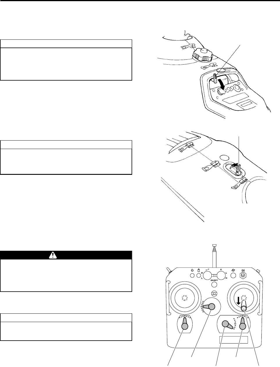
Flying Procedure
5-5
Engine Starting
1Pull and tilt the decompression lever on the con-
trol panel.
2Pull and raise the starter lever on the side cover
as needed.
3Check that the elevator trim lever, rudder trim
lever, and aileron trim lever are in center posi-
tion.
4Make sure the throttle stick on the transmitter is
in its slowest position.
Attempting to start the engine without oper-
ating the decompression lever could cause
the engine not to start or accelerate the wear
of the battery and the starter motor.
TIP Decompression Lever
●Use the starter lever if the engine is cold.
●Do not use the starter lever if the engine is
warm, such as restarting after a flight.
TIP
Starter Lever
If the elevator trim lever, rudder trim lever,
and aileron trim lever are not in center posi-
tion, the helicopter might not ascend straight
up at takeoff.
At this time, keep the throttle trim lever set to
the lowest position.
WARNING
TIP
Throttle Trim
Lever
Aileron Trim
Lever
Elevator Trim
Lever
Rudder Trim
Lever Throttle Stick
RMAX.book Page 5 Tuesday, January 17, 2012 3:06 PM
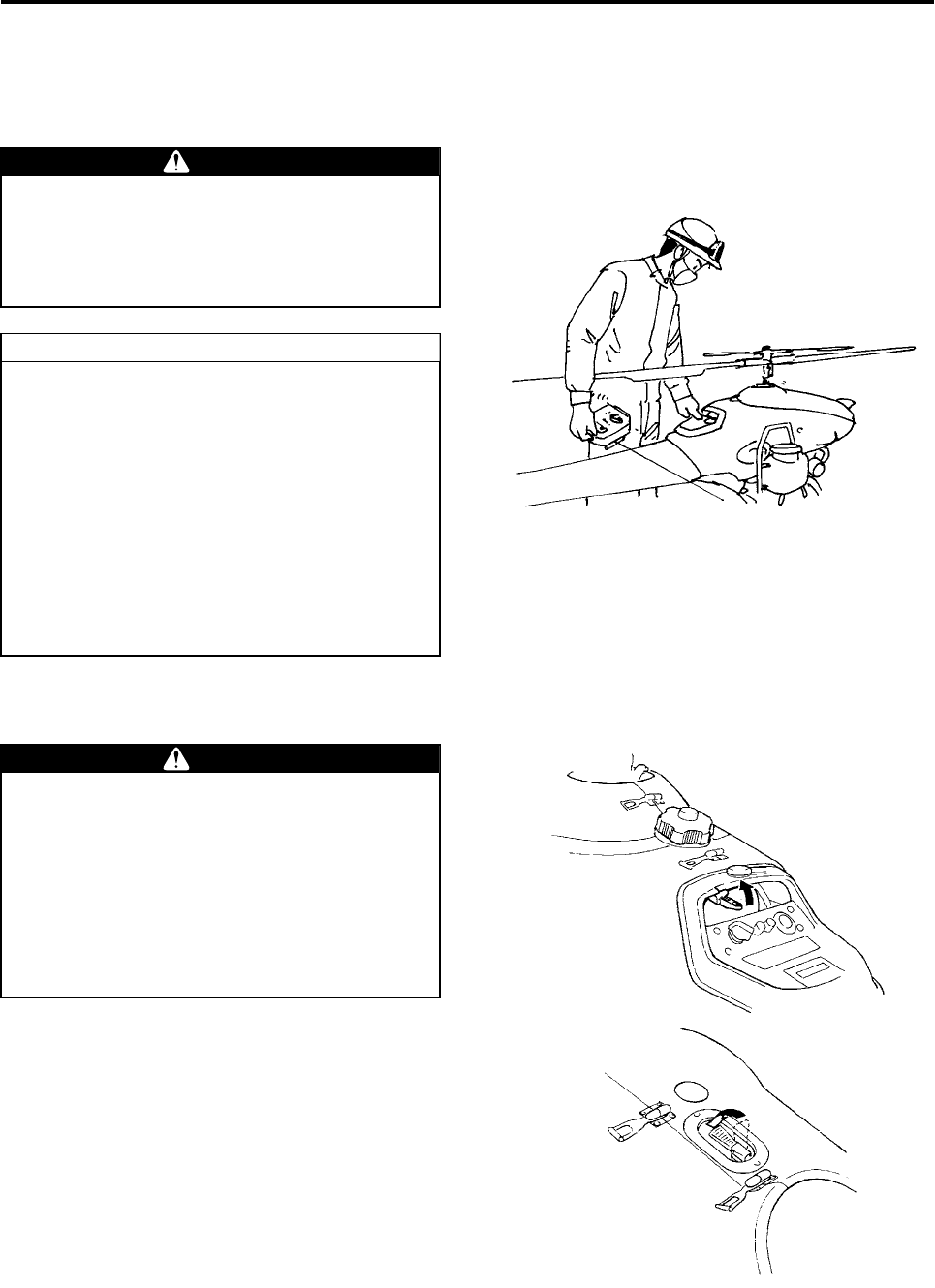
Flying Procedure
5-6
5Stand on the left side of the helicopter, and while
securely supporting the main rotor, keep the
throttle stick at the slowest position with your
right thumb, and press the starter switch with
your left hand.
6After the engine has started, return the decom-
pression lever and the starter lever to their origi-
nal position.
Support the main rotor with your body as
shown in the illustration. Otherwise, the rotor
could strike and injure you if the helicopter is
improperly adjusted (such as the idle speed
being too high or the clutch being engaged).
●If the engine does not start within 5 sec-
onds after pressing the starter switch, wait
about 10 seconds to allow the battery volt-
age to recover. Then, press the starter
switch again.
●The safety device will trip and prevent the
starter motor from operating if any of the
following conditions have not been met:
•Main switch is in the START position.
•The power switch of transmitter is ON.
•The throttle stick of the transmitter is in
the slowest position.
WARNING
TIP
●Failure to return the decompression lever
to its original position will decrease engine
performance, which could lead to an acci-
dent.
●Failure to return the starter lever will pre-
vent the engine speed from increasing,
cause the spark plugs to become fouled,
the engine to stop during flight, and lead
to an accident.
WARNING
RMAX.book Page 6 Tuesday, January 17, 2012 3:06 PM
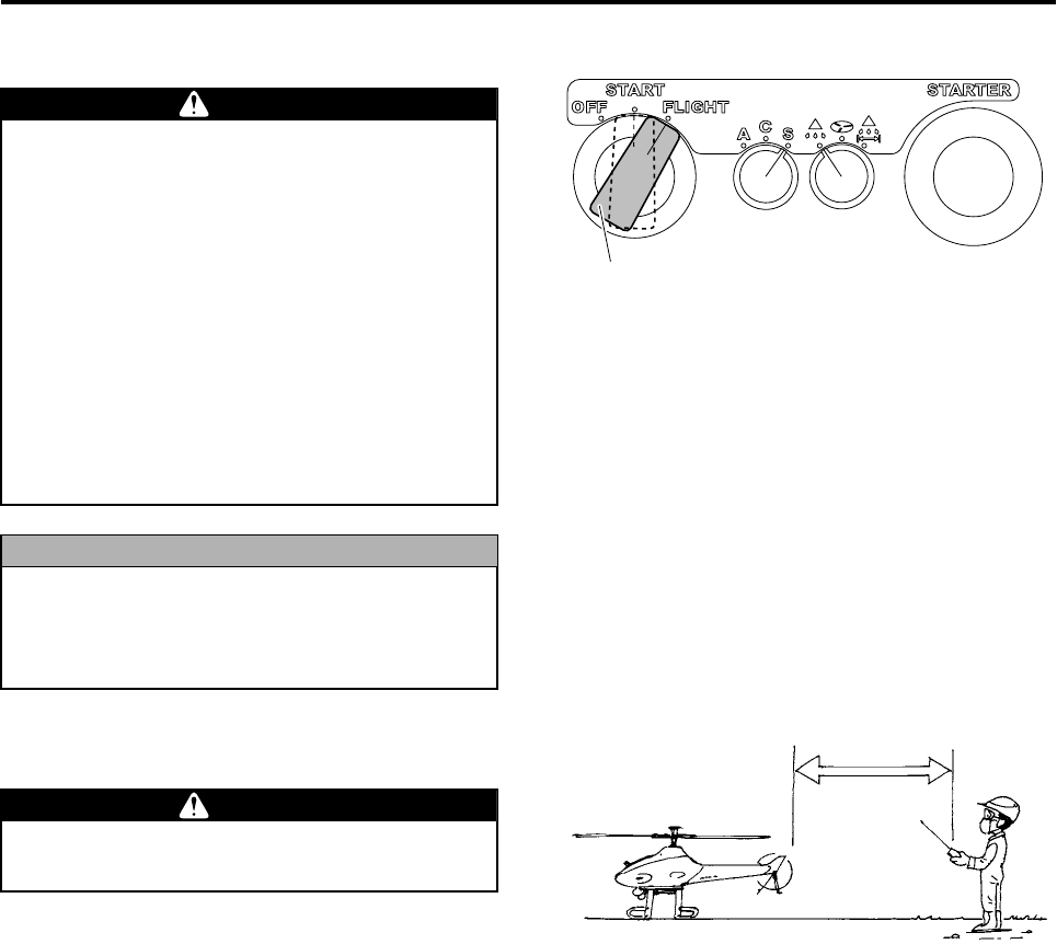
Flying Procedure
5-7
7After the engine speed has stabilized, turn the
main switch to the FLIGHT position.
8While making sure that the throttle stick does not
rise, quickly walk away from the helicopter, to a
minimum distance of 20 m.
●Before turning the main switch to FLIGHT,
check again that the throttle stick on the
transmitter is in its slowest position.
If the throttle stick is raised, the main rotor
or the tail rotor could spin and cause a
serious accident.
●The safety device will trip when the main
switch is in the START position, prevent-
ing the engine speed from increasing
above a predetermined value. If you hear
an abnormal sound from the engine, do
not turn the main switch to the FLIGHT
position. Instead, turn it OFF and check
the areas that are possibly affected.
Leaving the engine idling for more than 1
minute could stain the spark plug, or
decrease the cooling performance of the
engine.
DANGER
NOTICE
Main switch
Never turn your gaze away from the helicop-
ter when walking away from it.
DANGER
20m or more
RMAX.book Page 7 Tuesday, January 17, 2012 3:06 PM
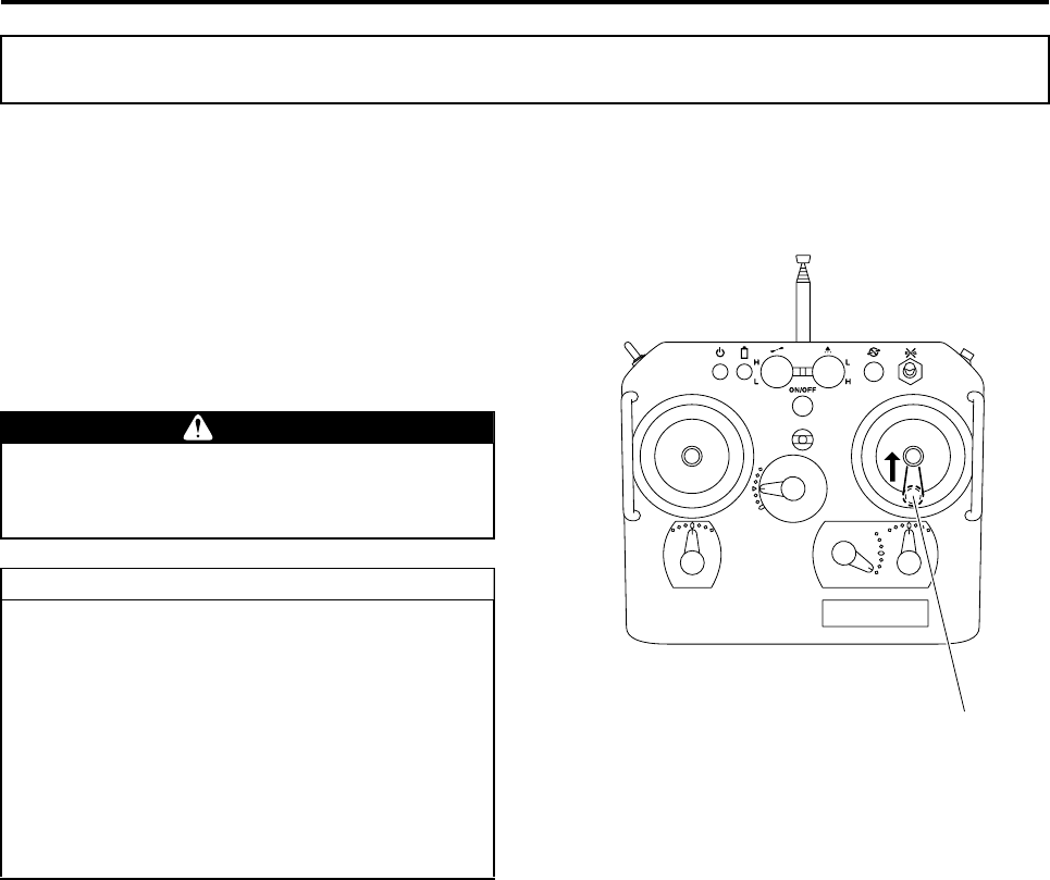
Flying Procedure
5-8
Takeoff Procedure
1Start the takeoff operation after the outer YACS
warning lights have finished flashing, and all
lights are OFF.
2Gradually raise the throttle stick to enable the
control to automatically increase the engine
speed.
3Slowly move the throttle stick up to take off.
Takeoff Precautions and Checks
Do not operate the sticks abruptly as this
could cause the helicopter to lose balance
and lead to an accident.
●If the throttle stick is moved far up while
the outer YACS warning lights are flashing,
the engine will stop.
●Do not operate the rudder excessively
right before a takeoff, as this will cause the
tail to move abruptly in the direction of the
rudder during a takeoff.
●During takeoff, do not turn ON the GPS
control switch, as this could cause the
helicopter to not ascend straight up.
WARNING
TIP
Throttle Stick
RMAX.book Page 8 Tuesday, January 17, 2012 3:06 PM
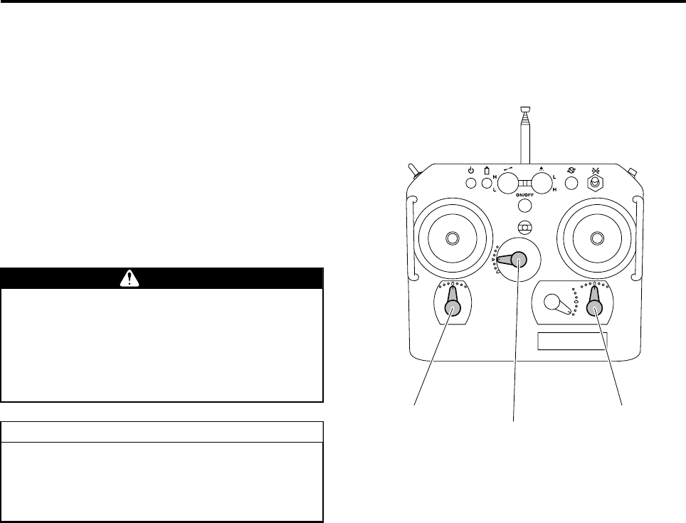
Flying Procedure
5-9
Post-Takeoff Checks
Perform the following checks:
1While the helicopter is hovering, make sure the
helicopter behaves normally in response to the
operations of the sticks.
2When the sticks are kept still in their neutral posi-
tion while the helicopter is hovering, the helicop-
ter will drift front-and-back and side-to-side,
depending on wind conditions. If the helicopter
drifts constantly in one direction, land it in a safe
area to make fine adjustments at the trim lever of
the transmitter.
For the first flight of the day, allow the heli-
copter to hover for 1 or 2 minutes while the
engine warms up, and check that the helicop-
ter operates normally. Failure to do so will
prevent the engine from attaining the proper
power, which could lead to an accident.
After takeoff, turn the GPS control switch ON
while hovering. If this switch was ON during
takeoff, turn it OFF while hovering, and turn it
back ON.
WARNING
TIP
Rudder Trim Lever
Elevator Trim Lever Aileron Trim Lever
RMAX.book Page 9 Tuesday, January 17, 2012 3:06 PM
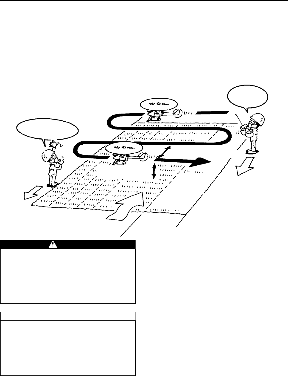
Flying Procedure
5-10
General Aerial Application Pattern
When operating an unmanned helicopter for the purpose of spraying agricultural chemicals, ensure safe oper-
ation, as well as the safety of humans, animals, agricultural products, and the environment during aerial appli-
cation.
Example: Disease and pest control of a rice paddy
•Flight altitude: 3 to 4 m
•Flying speed: 10 to 20 km/h
•Flying interval: 5 or 7.5 m
•Wind velocity: 3 m/s maximum
Affirmative!
Just passed 10 meters,
and 5 meters
Flying speed between
10 and 20 km/h
Flying height between
3 and 4 meters
Flying interval 5 or 7.5 meters
Wind
When performing tasks such as refueling,
never approach (or allow others to approach)
within 20 m of the helicopter until the main
rotor has come to a complete stop and the
engine has stopped. Entering within 20 m of
the helicopter could cause a serious acci-
dent.
If the GPS signal reception is good, the outer
YACS warning lights will illuminate if the fly-
ing velocity exceeds 20 km, regardless of the
state of the GPS control switch on the flight
transmitter (Velocity display function).
Control the flight velocity so that the outer
YACS warning lights do not illuminate.
DANGER
TIP
RMAX.book Page 10 Tuesday, January 17, 2012 3:06 PM
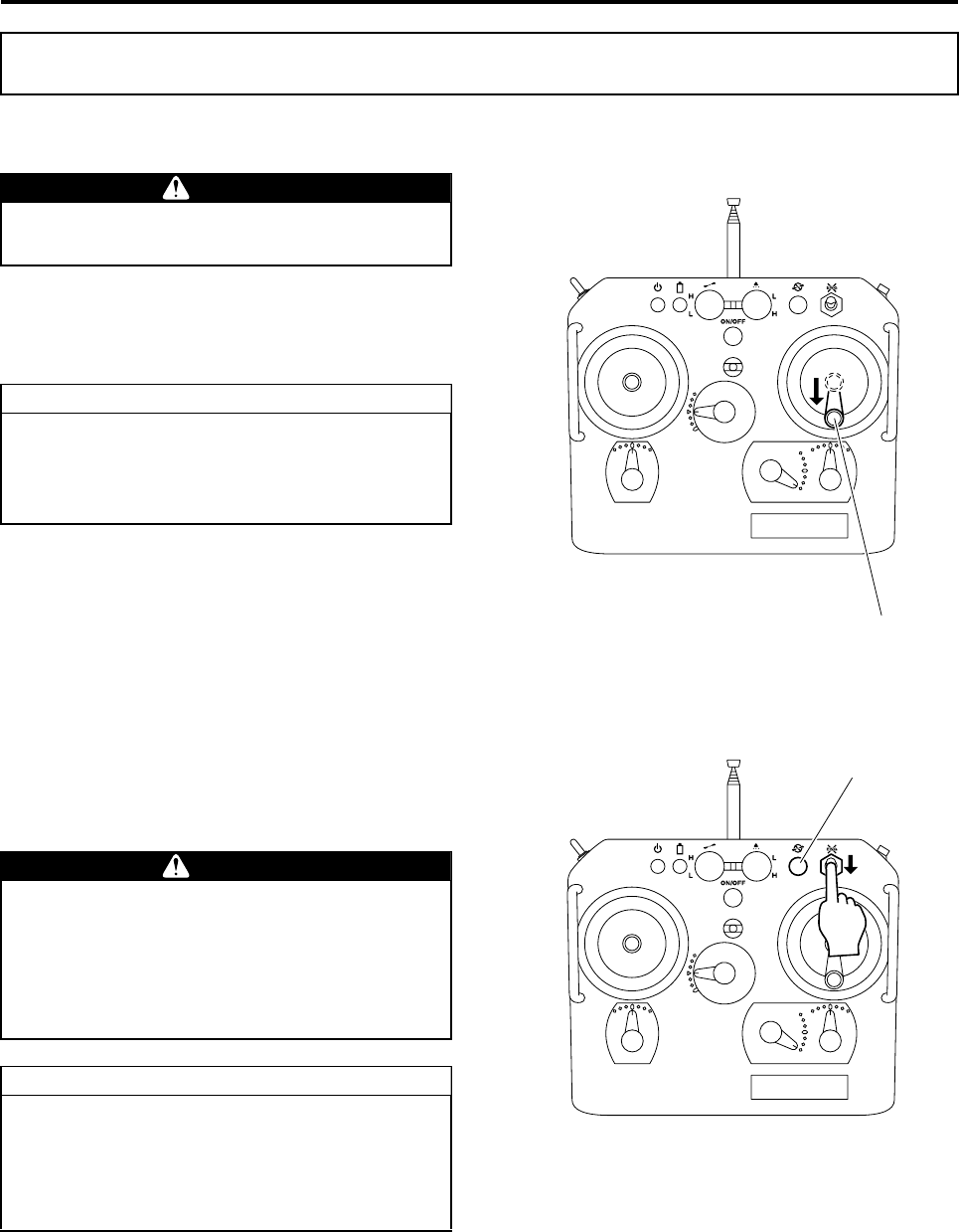
Flying Procedure
5-11
Landing
After hovering the helicopter over the landing point,
gradually lower the throttle stick to land it.
After landing, turns the GPS control switch OFF.
Engine Stopping
1After the engine speed has lowered, press down
the Engine Stop switch on the transmitter until
the engine comes to a complete stop.
2Press the Rotor Brake switch.
3Before turning OFF the main switch of the heli-
copter, check the self monitor’s check point indi-
cator and the malfunction area indicator lights for
any illumination or flashing.
Landing and Engine Stopping
Never allow anyone to approach within 20 m
of the helicopter.
If the engine speed does not lower within 3
seconds after landing, turn the YACS control
switch OFF. This will lower the engine speed
to idle.
DANGER
TIP
Throttle Stick
Never approach (or allow others to approach)
within 20 m of the helicopter until the main
rotor has come to a complete stop and the
engine has stopped. Entering within 20 m of
the helicopter could cause a serious acci-
dent.
●Do not press the Engine Stop switch
before the engine speed has dropped.
●The rotor brake will not apply unless the
throttle stick is placed in the slowest posi-
tion.
DANGER
TIP
1
2
RMAX.book Page 11 Tuesday, January 17, 2012 3:06 PM
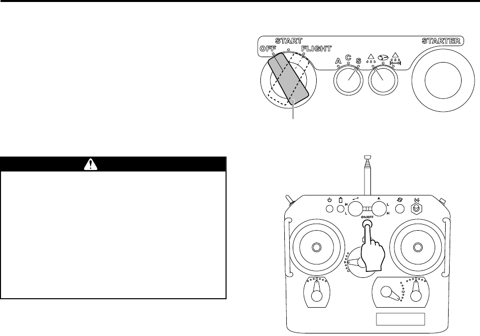
Flying Procedure
5-12
4Turn OFF the main switch of the helicopter.
5Turn OFF the power switch on the transmitter.
Main switch
Observe the following until the engine has
come to a complete stop:
•Do not turn OFF the power of the flight
transmitter.
•Do not take the battery out of the transmit-
ter.
Failure to observe these precautions will trip
the failsafe device (speed control turns ON
automatically), which will cause the engine to
accelerate suddenly.
WARNING
RMAX.book Page 12 Tuesday, January 17, 2012 3:06 PM

Flying Procedure
5-13
Fuel
After your dealer performs the complete inspection flight for the periodic inspection, the fuels are drained from
the fuel tank and the carburetor, to prevent the fuel from becoming old during your storage.
When flying for the first time, create a mixed fuel with fresh gasoline purchased at a gasoline station shortly
before flying (within 1 week), and refuel to maximum capacity.
Onboard Battery
Since the fuel has been drained, it will take a while before the fuel circulates into the carburetor.
If the engine does not start within 5 seconds after pressing the starter switch, wait about 10 seconds to allow
the battery voltage to recover and the starter motor to cool down. Then, press the starter switch again.
If the rotation of the starter motor is weak, replace the onboard battery, or have your dealer recharge it with the
dedicated recharger.
First Flight Procedure
In the periodic inspection, various parts of the helicopter are inspected, and a complete inspection flight is per-
formed. However, when flying for the first time after a periodic inspection, at a practice session, for example,
fly the helicopter gently as a means for the operator to familiarize himself with the various areas of the helicop-
ter as well as its maneuverability.
1Fill up the tank with fresh fuel. Keep the chemical and water load to one half of the normal load.
2Perform pre-flight inspection.
3After the engine starts, take off and hover no higher than 1 m above the ground for 2 minutes or longer.
4Next, while hovering 2 to 3 m above the ground, fly gently with flare angle of 10 degrees or less, at a flight
velocity of 10 km/h or less, for 10 minutes or longer. During this time, make sure that there is no vibration in
the helicopter, abnormal sound, or other abnormal behavior in response to the various stick operations.
5When landing for tasks such as refueling, always wait until the engine has stopped, and the main rotor has
stopped rotating, then open the side cover to visually check the coolant and oil leakage.
6After the flight, perform post-flight inspection, cleaning and servicing tasks.
Precautions for First Flight After Periodic Inspection
Never use leftover fuel as it could cause the engine to stop or operate poorly.
NOTICE
Never charge with a recharger for car batteries, or connect to a car battery using a jumper cable.
The electronics (computers) in the helicopter could malfunction.
NOTICE
RMAX.book Page 13 Tuesday, January 17, 2012 3:06 PM