Konishi Mokei L25-N4580 Transmitter for Radio Remote Control User Manual 2
JAPAN REMOTE CONTROL CO., LTD. Transmitter for Radio Remote Control 2
Contents
- 1. User manual 1
- 2. User manual 2
User manual 2

Post-Flight Inspection and Cleaning
Post-flight Inspection ................................................................ 6-1
Fuel Inspection ...................................................................................6-1
Coolant and Oil Inspections ..............................................................6-2
Rotor Blade Inspection ......................................................................6-2
Air Cleaner Inspection .......................................................................6-3
Servo and Linkage Inspection ...........................................................6-3
Self Monitor Inspection ......................................................................6-4
Tail Rotor Drive Belt Inspection ........................................................6-4
Antenna Inspection ............................................................................6-4
Post-Flight Cleaning and Servicing ......................................... 6-5
Washable Areas ..................................................................................6-6
Non-Washable Areas ..........................................................................6-7
6
RMAX.book Page 1 Tuesday, January 17, 2012 3:06 PM
6-1
Post-Flight Inspection and Cleaning
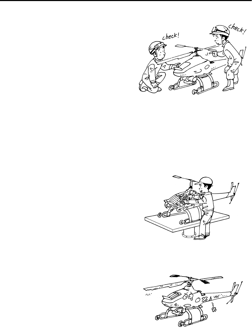
In preparation for the next flight, inspect the heli-
copter and make sure each area is free of prob-
lems. In addition, enter the results in the flight
inspection log.
Fuel Inspection
Inspect for fuel leakage.
Before performing this inspection, turn OFF both
the main switch for the helicopter and the power
switch for the transmitter.
For details, see page 4-19.
If you discover any fuel leakage, request a repair by
your dealer before the next flight.
Post-flight Inspection
●To prevent injury, make sure the engine is
stopped before performing an inspection.
●The helicopter is very hot immediately
after a flight. To prevent burns, allow the
temperature of the helicopter to lower suf-
ficiently before performing an inspection.
WARNING
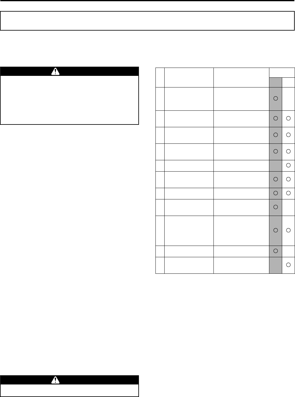
Inspection Point Inspection Items Flight
Pre Post
Transmitter
• Battery Level
• Operation
• Antenna installation
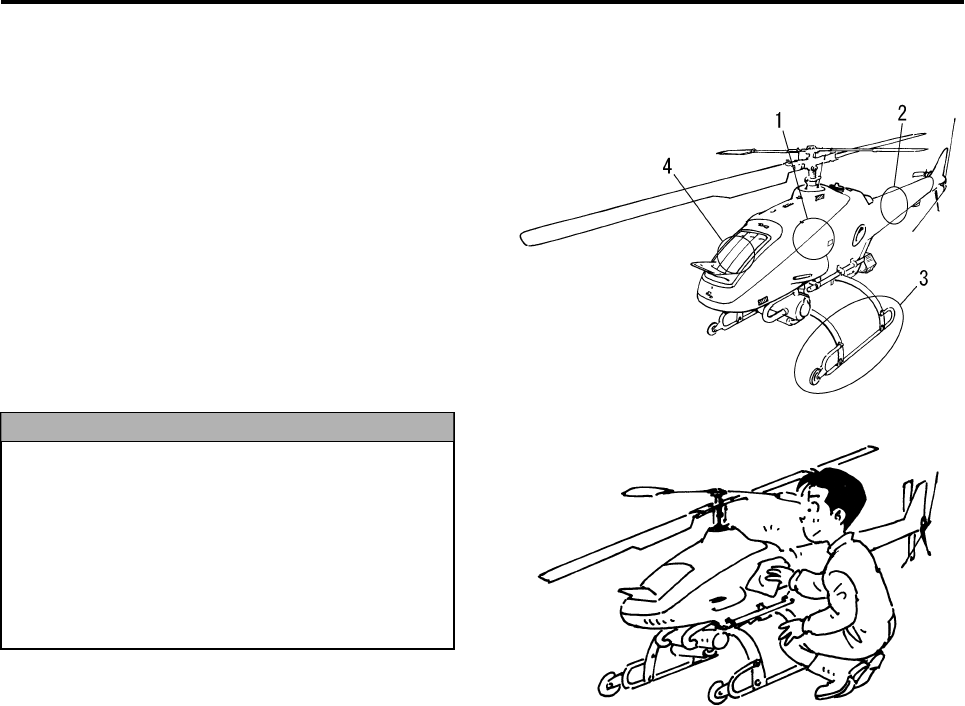
1 Fuel • Level
• Leakage
2 Coolant, oil • Level
• Leakage
3 Rotor blades • Dirtiness, damage
• Movement
4 Air cleaner • Dirtiness
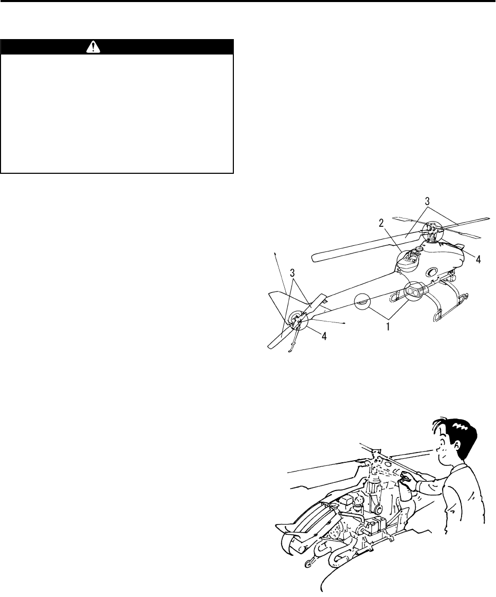
5Servo, linkage
(rudder, throttle)
• Operation
• Wobble
6 Self monitor • States of lighting
Radio signal
distance test
• Radio signal reach
7 Tail rotor drive belt
• Tension
• Abnormal noise
• Wear, damage
• Refuel
GPS system • States of lighting
8 Antenna • Installation state
• Rust
Fuel leakage could lead to a fire.
WARNING
RMAX.book Page 1 Tuesday, January 17, 2012 3:06 PM

Post-Flight Inspection and Cleaning
6-2
Coolant and Oil Inspections
Inspect the coolant level and check for any coolant
or oil leakage.
Before performing this inspection, turn OFF both
the main switch for the helicopter and the power
switch for the transmitter.
For details, see page 4-20.
A slight stain of coolant or oil does not indicate an
abnormal condition. However, if there are any drops
of coolant or oil leaking, request a repair by your
dealer before the next flight.
Rotor Blade Inspection
Inspect the rotor blades for damage, dirtiness, and
movement.
Before performing this inspection, turn OFF both
the main switch for the helicopter and the power
switch for the transmitter.
For details, see page 4-22.
If a rotor blade’s surface is dirty, use household
detergent on a soft cloth, wring out the cloth first,
and use it to wipe the rotor blade’s surface.
If a rotor blade is damaged, request a repair by your
dealer before the next flight.
●Coolant leakage will adversely affect the
cooling performance of the helicopter and
cause it to overheat.
●Transmission oil leakage will reduce the
internal lubrication of the transmission
and damage the gears and bearings.
NOTICE
If a main or tail rotor blade does not move
smoothly or is damaged, it could generate
noise or vibration.
NOTICE
RMAX.book Page 2 Tuesday, January 17, 2012 3:06 PM
Post-Flight Inspection and Cleaning
6-3
Air Cleaner Inspection
Inspect the air cleaner element for dirtiness.
Before performing this inspection, turn OFF both
the main switch for the helicopter and the power
switch for the transmitter.
Make sure the air cleaner element is free of debris,
dust, pollen, etc.
However, if the air cleaner element is dirty, replace
air cleaner with new ones before the next flight.
Servo and Linkage Inspection
Inspect the servos and linkages for proper opera-
tion.
Before performing this inspection, turn the power
switch for the transmitter to ON and the main switch
for the helicopter to START.
For details, see page 4-23.
If the servos operate abnormally or the linkages
wobble, request a repair by your dealer before the
next flight.
A dirty or clogged air cleaner element will
adversely affect the performance of the
engine.
NOTICE
Air cleaner
●If the servos operate abnormally or the
linkages wobble, they could adversely
affect the control of the helicopter.
●If the throttle operates abnormally, it could
adversely affect engine control, which
could cause the helicopter to go out of
control.
WARNING
RMAX.book Page 3 Tuesday, January 17, 2012 3:06 PM
Post-Flight Inspection and Cleaning
6-4
Self Monitor Inspection
Inspect the illumination of the indicator lights on the
self monitor for proper operation.
Before performing this inspection, turn the power
switch for the transmitter to ON and the main switch
for the helicopter to START.
For details, see the table on page 3-5.
If the lights illuminate abnormally, request a repair
by your dealer before the next flight.
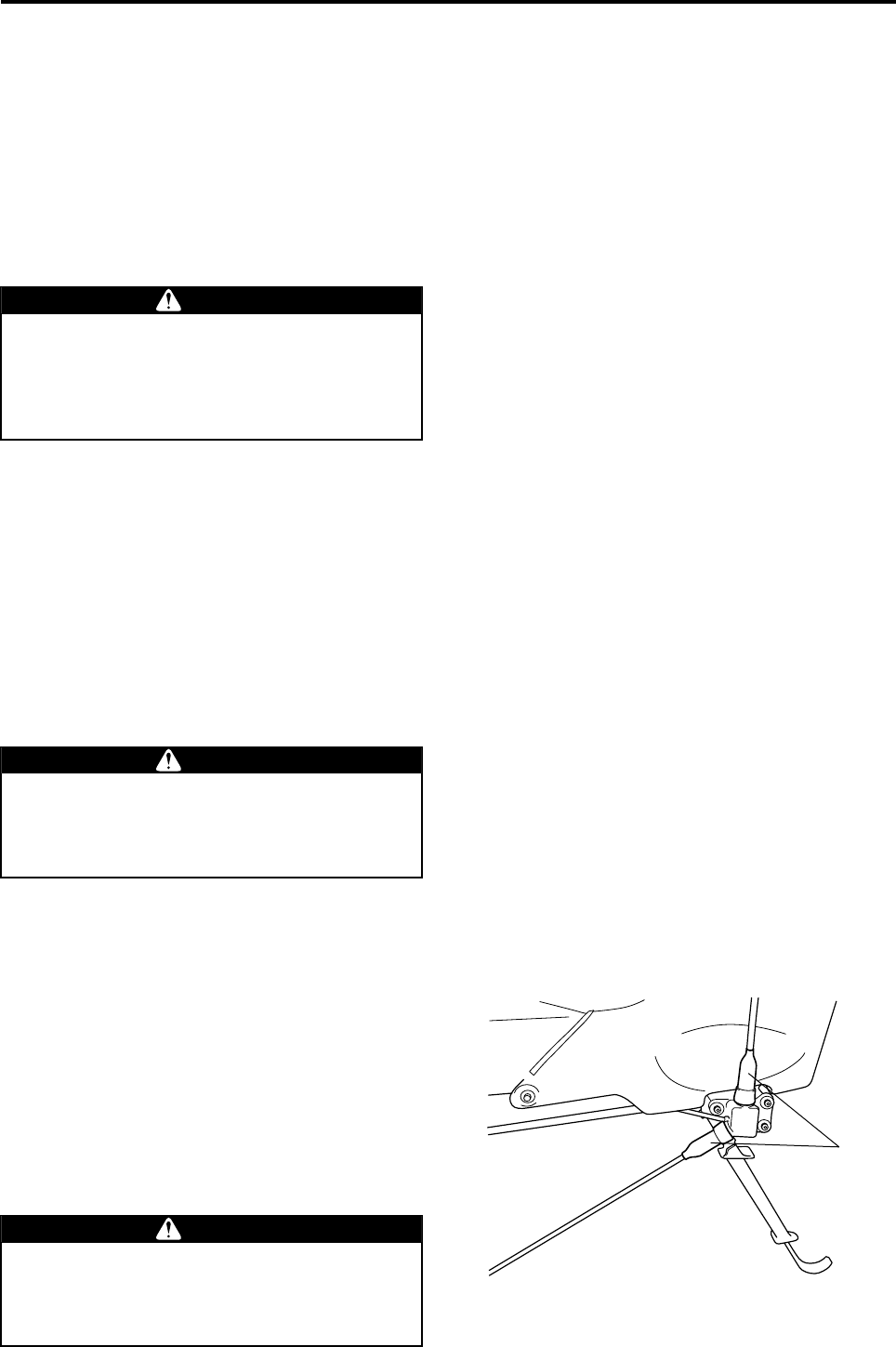
Tail Rotor Drive Belt Inspection
Inspect the condition of the tail rotor drive belt and
apply lubricant to the belt.
Before performing this inspection, turn OFF both
the main switch for the helicopter and the power
switch for the transmitter.
For details, see page 4-25.
If there is a problem with the belt, request a repair
by your dealer before the next flight.
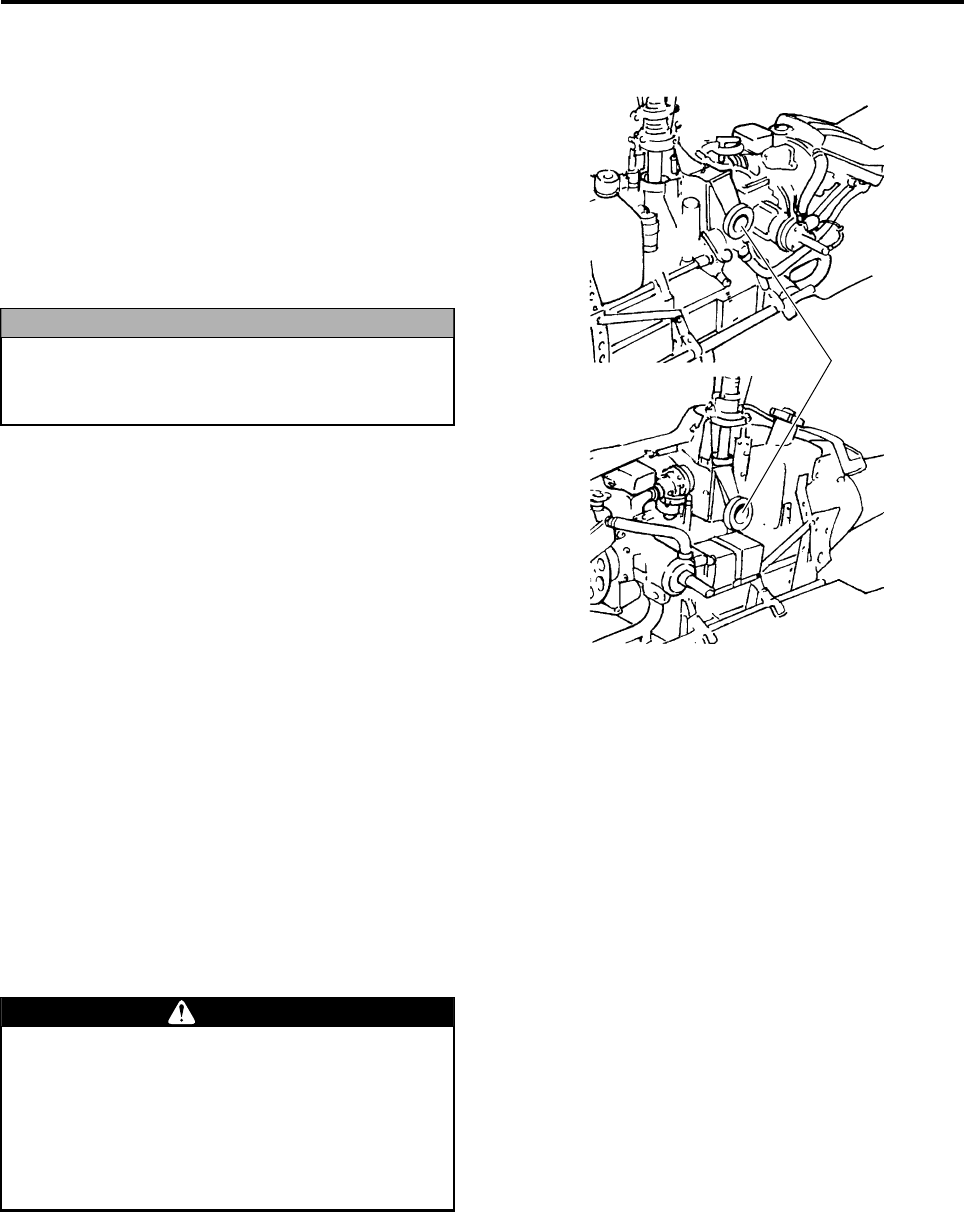
Antenna Inspection
Inspect the antenna to make sure it is not loose or
rusted at the area where it is mounted to the heli-
copter.
Before performing this inspection, turn OFF both
the main switch for the helicopter and the power
switch for the transmitter.
Peel the dust cover from the base of each antenna
pole and make sure the antenna poles are not
loose or rusted.
If they are loose or rusted, request a repair by your
dealer before the next flight.
Take the appropriate actions in accordance
with the indicator lights. By ignoring the
lights and continuing to fly, you will lose con-
trol of the helicopter and cause a serious
accident.
WARNING
If there is a problem with the tail rotor drive
belt, it could adversely affect the actuation of
the tail rotor, which could cause the helicop-
ter to go out of control.
WARNING
If the antenna is loose or rusted, it will affect
the reception of control signals, which could
cause the helicopter to go out of control dur-
ing flight.
WARNING
Dust Covers
RMAX.book Page 4 Tuesday, January 17, 2012 3:06 PM
Post-Flight Inspection and Cleaning
6-5
Agricultural chemicals, dust, dead bugs, and pollen
could adhere to the helicopter after an aerial appli-
cation.
If they remain stuck to the helicopter, they will
cause a chemical reaction, which will lead to rust,
insufficient lubrication, sealant deterioration, and
discoloring.
To prevent these problems, use the methods
described below to clean and service the helicopter
after a flight, in preparation for the next flight. While
cleaning, check all areas of the helicopter for any
damage, abnormal wear, loose fasteners, etc.
Post-Flight Cleaning and Servicing
The helicopter is very hot immediately after a
flight. Therefore, to prevent burns, clean it
only after its temperature has lowered suffi-
ciently.
Washing the helicopter with water will cause
a sudden change in temperature, which
could create problems in electrical parts.
Therefore, clean it only after its temperature
has lowered sufficiently.
WARNING
NOTICE
RMAX.book Page 5 Tuesday, January 17, 2012 3:06 PM
Post-Flight Inspection and Cleaning
6-6
Washable Areas
1 Side covers
They may be washed only after they have been
removed from the helicopter.
Do not wash them in the installed state because
the water could splash on other parts.
2 Tail body
Clean it carefully while making sure to prevent
the GPS system and the gyro sensor from direct
contact with water.
3 Leaves and runners
4Radiator
Clean it by using caution not to damage the fins.
Do not use a high-temperature, high-pres-
sure cleaner to clean areas 1 to 4 above, as it
could damage the film and paint on the sur-
face.
After cleaning the washable areas of the heli-
copter with water, ensure to wring out your
cloth before you wipe the moisture off the
surface.
NOTICE
RMAX.book Page 6 Tuesday, January 17, 2012 3:06 PM
Post-Flight Inspection and Cleaning
6-7
Non-Washable Areas
1 GPS System and Azimuth sensor
Washing these areas with water will cause them
to malfunction as a result of exposure of the
internal components to water.
Therefore, use a soft, moist cloth that has been
wrung out to wipe the dirty areas.
2 Control Panel
Washing these areas with water will cause the
hour meter, GPS antenna, switches, and the
monitor lights to malfunction as a result of expo-
sure of the internal components to water.
Therefore, use a soft, moist cloth that has been
wrung to wipe the dirty areas.
3 Main and Tail Rotor Blades
Washing these areas with water will cause the
rotors to lose their balance and create vibrations
as a result of exposure of the internal compo-
nents to water.
If the rotor surface is dirty, use household deter-
gent on a soft cloth, wring the cloth, and use it to
wipe the rotor surface.
4 Main and Tail Rotor Head Areas
Washing these areas with water will adversely
affect the lubrication of the bearings and slides,
which could damage or wear those parts.
Therefore, use a soft, moist cloth that has been
wrung out to wipe the dirty areas.
Apply a small amount of the dealer-specified
anti-rust lubricant to the bearings, rod ends, and
sliding portions of parts, and then wipe them with
a dry cloth.
The helicopter and the transmitter have a
drip-proof construction and not a water-proof
construction. Therefore, do not use water
directly on areas other than those indicated
in the previous section.
Failure to observe this precaution could
cause the electric parts or the sliding areas
to malfunction, which could lead to a serious
accident.
WARNING
RMAX.book Page 7 Tuesday, January 17, 2012 3:06 PM
Post-Flight Inspection and Cleaning
6-8
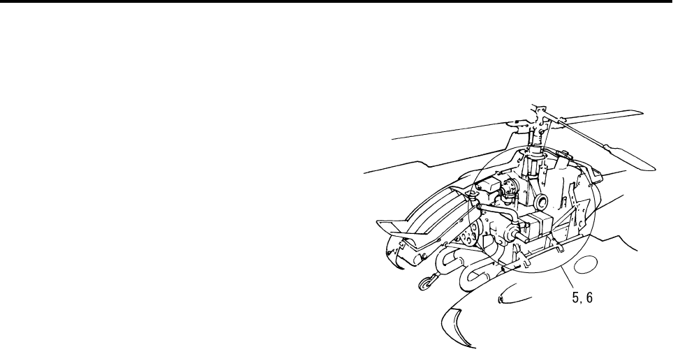
5 Servos and Electrical Parts
Washing these areas with water will cause them
to malfunction as a result of exposure of the
internal components to water.
6 Frame
Washing this area with water will cause the
YACS control to malfunction as a result of expo-
sure of the internal electric components to water.
Therefore, use a soft, moist cloth that has been
wrung out to wipe the dirty areas.
7 Flight Transmitter
Washing this area with water will cause the
transmitter to malfunction as a result of exposure
of the internal switches and electric components
to water. Therefore, use a soft, moist cloth that
has been wrung out to wipe the dirty areas.
RMAX.book Page 8 Tuesday, January 17, 2012 3:06 PM

Post-Flight Inspection and Cleaning
6-9
RMAX.book Page 9 Tuesday, January 17, 2012 3:06 PM

Simple Maintenance
Battery Recharging Procedure ................................................. 7-1
7
RMAX.book Page 1 Tuesday, January 17, 2012 3:06 PM
7-1
Simple Maintenance
This helicopter uses a sealed battery.
It is not necessary to refill or inspect the battery
fluid.
If there is any abnormality in the battery, request a
repair by your dealer.
Battery Recharging Procedure
The battery produces flammable gas (hydro-
gen gas). Mishandling it could lead to an
explosion resulting in injuries. Make sure to
observe the following:
●Fire is strictly prohibited. Do not short a
circuit, cause a spark, or let any fire such
as cigarettes come near. This could cause
an explosion.
●Do not connect to the battery terminals in
the wrong order. Doing so could cause a
fire.
●Recharge in a well ventilated place.
●Keep gasoline, oil, or organic solvent from
getting on the battery, as this could cause
the battery case to crack.
●Do not drop it or apply any other strong
impact.
●The battery fluid is diluted sulfuric acid.
Contact with the skin, eye, or clothing
could lead to a serious injury.
●Keep out of reach of children.
First Aid
●In the unlikely event that the battery fluid
gets on the skin, clothing, etc., immedi-
ately rinse with copious amounts of water.
●If it enters the eye, immediately rinse it
with copious amounts of water, and seek
medical attention.
●This is a sealed 12V battery.
●This battery has been filled with fluid and
charged. No fluid level inspection or refill-
ing is necessary.
●For recharging, use the dedicated sealed
battery recharger. Contact your dealer for
details.
●If the battery is to be left unused for a long
time, remove the battery from the helicop-
ter, and recharge every 3 months.
●When replacing the battery, make sure to
use a genuine battery.
WARNING
NOTICE
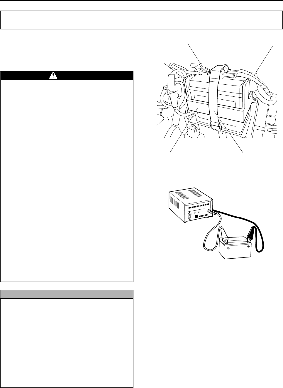
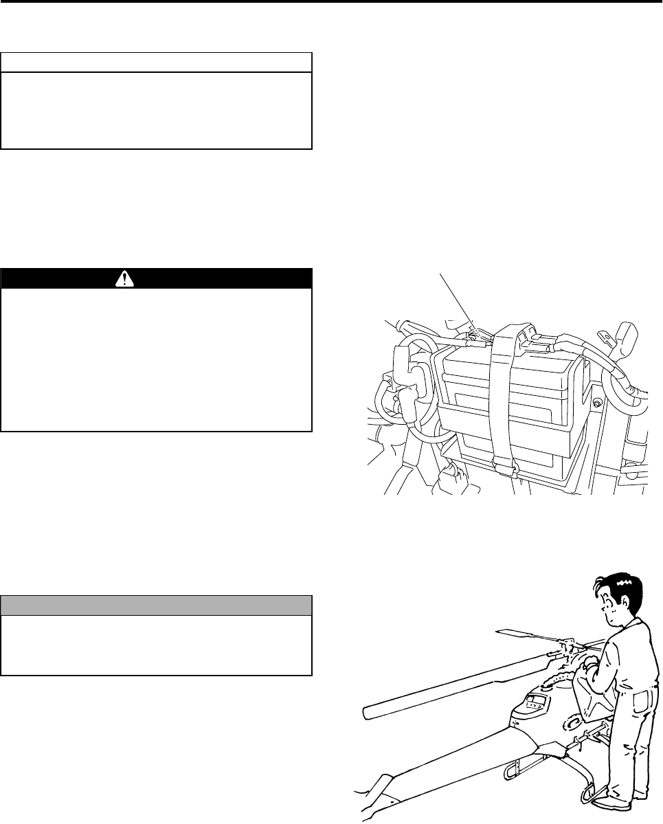
+Terminal (red cap) -Terminal (black cap)
Battery Battery Support Strap
RMAX.book Page 1 Tuesday, January 17, 2012 3:06 PM

Simple Maintenance
7-2
Removing the Battery
1Make sure to turn OFF the main switch on the
control panel.
2Disconnect the negative - and positive + termi-
nals of the battery, in that order.
3Remove the battery support strap and take the
battery out of the helicopter.
Reinstalling the Battery
Reinstall the battery in reverse order of removal.
●Batteries are consumables.
●The battery should be replaced every year.
TIP
RMAX.book Page 2 Tuesday, January 17, 2012 3:06 PM

Simple Maintenance
7-3
RMAX.book Page 3 Tuesday, January 17, 2012 3:06 PM

Proper Management
Storage Precautions .................................................................. 8-1
Daily Storage Procedure ....................................................................8-2
Long-Term Storage Procedure ..........................................................8-2
Operating the Helicopter After Long-Term Storage ........................8-3
Other Types of Management .................................................... 8-5
8
RMAX.book Page 1 Tuesday, January 17, 2012 3:06 PM
8-1
Proper Management
This unmanned helicopter for industrial applications
has been manufactured for the purpose of aerial
application of agricultural chemicals, fertilizers, and
seeds.
Secure a storage location for the helicopter and its
auxiliary devices, to prevent theft and illegal use
outside of its intended purpose, such as criminal
acts.
As a measure to prevent illegal use, this product is
equipped with the following features:
•Areas of use are limited
•Specified operation period
•Specified total operation time
To select a storage site, consider factors such as
sources of fire or spark, temperature, humidity,
dust, theft, and the presence of any stacked loads
in the area.
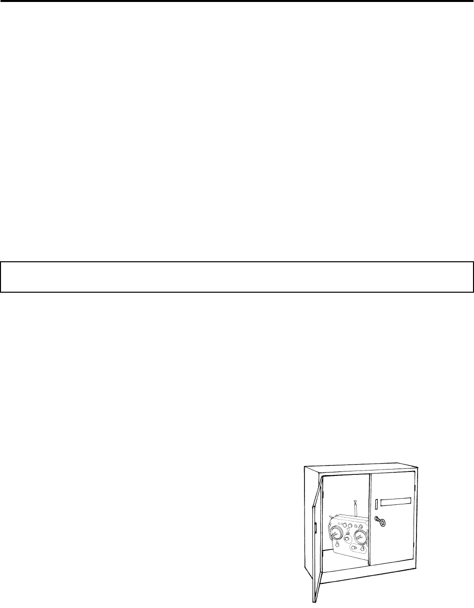
We recommend that you provide a dedicated cabi-
net for storing the auxiliary devices.
In addition to protecting the helicopter from damage
and theft, or the auxiliary devices from loss, these
measures will facilitate the monitoring of their main-
tenance conditions and ensure efficient preparation
for the next flight.
1Store the helicopter, rotors, and transmitters in
separate, lockable locations so that they will not
be stolen or subject to other criminal acts.
2If the helicopter is stolen, immediately report the
theft to your dealer. Then, contact your local
police department.
Storage Precautions
RMAX.book Page 1 Tuesday, January 17, 2012 3:06 PM
Proper Management
8-2
Daily Storage Procedure
1Perform “Post-flight Inspection” (P6-1) and
record the results in the flight log.
2Clean the helicopter. (See page 6-5.)
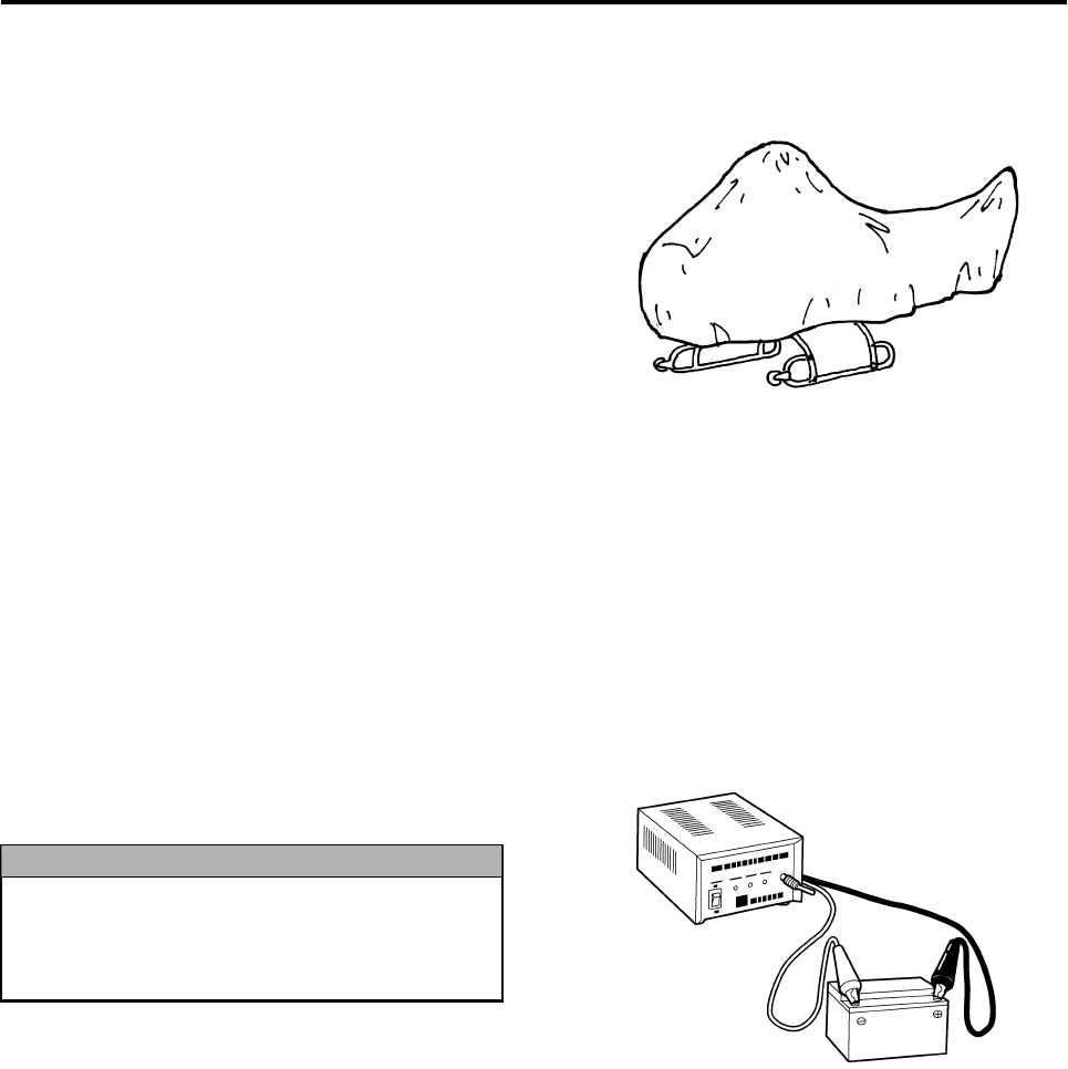
3Place the helicopter cover (sold separately) and
store it indoors, in an area that is not damp.
4Clean the flight transmitter and remove its bat-
tery. (See page 4-2.)
Long-Term Storage Procedure
If the helicopter will not be operated for a few
months, follow the storage procedure given below
in preparation for the subsequent operation.
1Perform “Post-flight Inspection” (P6-1) and
record the results in the flight log.
2Clean the helicopter. (See page 6-5.)
3Remove the onboard battery and recharge it with
a dedicated recharger. (See page 7-1.)
After recharging, store the battery in a cool and
dark location, and recharge it every 3 months.
4Fuel must be drained from the fuel tank and the
carburetor. Request the performance of this
operation by your dealer.
5Place the helicopter cover and store it indoors, in
an area that is not damp.
6Clean the flight transmitter and remove its bat-
tery. Store the battery in a cool and dark loca-
tion.
To disconnect the battery, first disconnect its
negative terminal, followed by the positive
terminal. Reversing this order could cause
the battery to short.
NOTICE
RMAX.book Page 2 Tuesday, January 17, 2012 3:06 PM
Proper Management
8-3
Operating the Helicopter After Long-Term Storage
To operate the helicopter after storing it for a few
months, perform the following preparations:
1Install fully charged batteries in the helicopter
and the flight transmitter, after making sure the
main switch on the helicopter is turned OFF.
2Prepare fresh fuel and pour it in the fuel tank.
(See page 4-4.)
●Have a periodic inspection performed on
the helicopter if you will be operating it
after prolonged storage of 1 year or more.
●Contact your dealer for details.
TIP
●Do not interchange the positive and nega-
tive poles when connecting the battery ter-
minals, as it could cause a fire or
malfunction.
●To connect the battery, first connect its
positive terminal, followed by the negative
terminal. Reversing this order could cause
the battery to short.
WARNING
Connect the positive terminal first
Never use old leftover fuel.
This could cause the engine to stop or oper-
ate poorly
NOTICE
RMAX.book Page 3 Tuesday, January 17, 2012 3:06 PM
Proper Management
8-4
3Perform pre-flight inspections. (See page 4-17.)
4Start the engine. After prolonged storage, the
engine will be hard to start because it will take a
while for the fuel to reach the carburetor.
Repeat the cycle of operating the starter motor for 5
seconds and waiting 10 seconds, 4 or 5 times. This
will allow the fuel to reach the carburetor and the
engine to start.
If the engine does not start within 5 seconds
after you have pressed the starter switch,
wait about 10 seconds to allow the battery
voltage to recover. Then, press the starter
switch again.
TIP
RMAX.book Page 4 Tuesday, January 17, 2012 3:06 PM

Proper Management
8-5
This helicopter and some parts fall under the list-
controlled items of Japan’s “Foreign Exchange and
Foreign Trade Act”. Use sufficient care to ensure
that the list-controlled items are not stolen or lost.
Other Types of Management
RMAX.book Page 5 Tuesday, January 17, 2012 3:06 PM

Troubleshooting
Engine ......................................................................................... 9-1
Helicopter ................................................................................... 9-4
YACS ........................................................................................... 9-6
GPS ............................................................................................. 9-7
Flight Transmitter ...................................................................... 9-8
Sprayer ....................................................................................... 9-9
9
RMAX.book Page 1 Tuesday, January 17, 2012 3:06 PM
9-1
Troubleshooting
The problems listed here can be handled primarily
by the user.
Problems or causes that are not listed here are
handled by your dealer. If such problems occur,
cancel the flight and contact your dealer to have the
helicopter inspected and repaired.
Starter motor does not operate
The starter motor does not operate, and all 3 flight indicator lights,
“”, “”, and “” illuminate simultaneously.
Engine does not start
●Make sure to follow the instructions given
in the “User Action” column, and do not
take any actions that are not called for.
●If you have any questions, be sure to con-
tact your dealer. If an inspection, adjust-
ment, or part replacement is performed by
a person who does not possess the kno-
whow and proficiency to service the heli-
copter, it could lead to a serious accident.
WARNING
Engine
Main Cause User Action Remarks
1Main switch on the helicopter is not turned to
START. Turn the main switch on the helicopter to START. See page 5-3.
2 Power switch of the flight transmitter is not ON. Turn ON the power switch of the flight transmitter. See page 5-3.
3Throttle stick on the flight transmitter is not in the
SLOWEST position.
Move the throttle stick of the flight transmitter to
the SLOWEST position. See page 5-5.
4 Decompression is not operating. Operate the decompression lever. See page 5-5.
5 Helicopter battery terminals are loose. Firmly tighten the battery terminals. See page 7-1.
6 Onboard battery is faulty. Recharge the battery with a dedicated recharger,
or replace it. See page 7-1.
Main Cause User Action Remarks
1 Request your dealer for repair.
Main Cause User Action Remarks
1 There is no fuel. Pour fresh fuel in the tank. See page 4-4.
2 Poor quality fuel (old fuel) Request your dealer for repair.
3 Carburetor starter does not operate. Operate the starter lever. See page 5-5.
4 Spark plugs are faulty. Immediately stop the flight and request a repair
by your dealer.
5 Spark plug caps are improperly installed. Install the spark plug caps properly.
6 Starter motor spins slowly. Recharge the onboard battery with a dedicated
recharger. See page 7-1.
RMAX.book Page 1 Tuesday, January 17, 2012 3:06 PM

Troubleshooting
9-2
Engine speed does not increase
Engine has no power
Engine overheats
Coolant gushed out of recovery tank
Main Cause User Action Remarks
1Main switch on the helicopter is not turned to
FLIGHT. Turn the main switch on the helicopter to FLIGHT. See page 5-7.
2 Starter lever has not been returned. Return the starter lever. See page 5-6.
3 Decompression lever has not been returned. Return the decompression lever. See page 5-6.
4 Air cleaner element is dirty or clogged. Immediately stop the flight and replace air cleaner
with new ones.
5 Spark plugs are faulty. Immediately stop the flight and request a repair
by your dealer.
Main Cause User Action Remarks
1 Engine overheats. Immediately stop the flight, and check the con-
tents in the next section “Engine overheats”.
2 Spark plugs are faulty. Immediately stop the flight and request a repair
by your dealer.
3 Air cleaner element is dirty or clogged. Immediately stop the flight and replace air cleaner
with new ones.
Main Cause User Action Remarks
1 Coolant is leaking or insufficient.
Replenish coolant.
If coolant is leaking, request a repair by your
dealer.
See page 4-20.
2 Specified coolant is not used. Use the dealer-specified coolant and tap water
with the proper mixing ratio. See page 4-20.
3 Radiator is dirty or its fins are clogged. Clean the radiator. See page 6-6.
4 Radiator fan motor is not operating.
If the motor does not operate when the main
switch on the helicopter is turned to FLIGHT,
request a repair by your dealer.
5 Engine load is excessive. Reduce the payload. See page 4-10.
Main Cause User Action Remarks
1 Engine overheats. Immediately stop the flight, and check the con-
tents in the previous section “Engine overheats”.
RMAX.book Page 2 Tuesday, January 17, 2012 3:06 PM

Troubleshooting
9-3
Helicopter emits a burning smell
Engine idle is unstable
Engine idle is too high
Engine speed does not decrease after landing
Exhaust emits excessive smoke
Engine makes noise
Main Cause User Action Remarks
1 Engine overheats. Immediately stop the flight, and check the con-
tents in “Engine overheats” on page 9-2.
2 Oil is leaking. Immediately stop the flight and request a repair
by your dealer.
3 Wires are burned. Immediately stop the flight and request a repair
by your dealer.
Main Cause User Action Remarks
1 Spark plugs are faulty. Immediately stop the flight and request a repair
by your dealer.
2 Spark plug caps are improperly installed. Install the spark plug caps properly.
3 Starter lever has not been returned. Return the starter lever. See page 5-6.
4 Idle speed is too low. Slightly raise the throttle trim lever on the flight
transmitter.
Main Cause User Action Remarks
1 Throttle trim lever is improperly adjusted. Lower the throttle trim lever.
2Carburetor throttle valve is not in contact with stop
screw.
Check the operation of the carburetor.
If it does not close fully, request a repair by your
dealer.
See page 4-23.
Main Cause User Action Remarks
1Sensor operates abnormally due to a large shock
sustained during landing.
Land the helicopter more gently.
Turn OFF the YACS control switch. See page 5-11.
Main Cause User Action Remarks
1 Gasoline and oil mixing ratio is improper. Replace the fuel. See page 4-4.
2 Specified oil is not used. Use the Yamaha-specified oil. See page 4-4.
Main Cause User Action Remarks
1Engine is damaged internally or lubricated insuffi-
ciently.
Immediately stop the flight and request a repair
by your dealer.
RMAX.book Page 3 Tuesday, January 17, 2012 3:06 PM

Troubleshooting
9-4
Helicopter vibrates
Helicopter cannot take off
Helicopter makes noise during takeoff
Helicopter descends after takeoff
Helicopter
Main Cause User Action Remarks
1 Main rotor blades are positioned improperly. Install the rotor blades by matching their color
marks. See page 4-15.
2Main rotor or tail rotor retaining bolts are tightened
improperly.
Follow the specified tightening procedure to
tighten the bolts. See page 4-15.
3 Main rotor or tail rotor is damaged. Immediately stop the flight and request a repair
by your dealer. See page 4-22.
4Cushion tape has peeled from the main rotor or
tail rotor.
Immediately stop the flight and request a repair
by your dealer. See page 4-22.
5 Tracking of the main rotor or tail rotor is faulty. Immediately stop the flight and request a repair
by your dealer.
6 Main rotor or tail rotor is imbalanced. Immediately stop the flight and request a repair
by your dealer.
7 Chemical tank is improperly installed. Securely install the chemical tank.
See the opera-
tion manual for
the sprayer.
Main Cause User Action Remarks
1 Engine speed does not increase.
Immediately stop the flight, and check the con-
tents in “Engine speed does not increase” on
page 9-2.
2 Engine lacks power. Immediately stop the flight, and check the con-
tents in “Engine has no power” on page 9-2.
3 Payload is excessive. Reduce the payload. See page 4-10.
Main Cause User Action Remarks
1 Tail belt is loose. Immediately stop the flight and request a repair
by your dealer. See page 4-25.
2 Bolts of parts are loose. Check all parts for loose bolts.
Main Cause User Action Remarks
1 Engine lacks power. Immediately stop the flight, and check the con-
tents in “Engine has no power” on page 9-2.
2 Payload is excessive. Reduce the payload. See page 4-10.
3 Throttle stick is operated improperly.
Operate the throttle stick by making sure the
amount of its movement does not decrease dras-
tically.
RMAX.book Page 4 Tuesday, January 17, 2012 3:06 PM

Troubleshooting
9-5
Helicopter moves considerably in rudder direction after takeoff
Helicopter drifts in one direction
Helicopter descends when flare (brake) is applied
Helicopter moves considerably in rudder direction when flare
(brake) is applied
Main Cause User Action Remarks
1 Rudder was operated excessively before takeoff. Do not operate the rudder excessively when tak-
ing off with the YACS control ON. See page 5-8.
Main Cause User Action Remarks
1 Trim is adjusted improperly. Adjust the trims on the flight transmitter. See page 5-9.
Main Cause User Action Remarks
1Rotor lift decreased due to an abrupt flare opera-
tion. Do not operate the flare abruptly. See page 5-8.
2 Payload is excessive. Reduce the payload. See page 4-10.
Main Cause User Action Remarks
1Helicopter lost its balance due to an abrupt flare
operation. Do not operate the flare abruptly. See page 5-8.
RMAX.book Page 5 Tuesday, January 17, 2012 3:06 PM
Troubleshooting
9-6
YACS warning light illuminates or flashes
Self monitor light other than “” illuminates
YACS control configuration takes time
“” indicator light remains ON even after refueling
YACS
Main Cause User Action Remarks
1Identifiable through the illumination or flashing
pattern.
Immediately stop the flight and take appropriate
actions accordance to the information on page 3-
7.
See page 3-7.
Main Cause User Action Remarks
1 Identifiable through the illumination location.
Immediately stop the flight and take appropriate
actions accordance to the information on page 3-
5.
See page 3-5.
Main Cause User Action Remarks
1 Helicopter is not still.
Allow the YACS control to configure itself on a flat
surface. (Configuration will not complete if the
helicopter is tilted or moving.)
See page 5-4.
Main Cause User Action Remarks
1 Fuel temperature is too high.
Keep the refueling tank in a shade because the
fuel in it will reach a high temperature if the tank is
left under a scorching sun.
RMAX.book Page 6 Tuesday, January 17, 2012 3:06 PM
Troubleshooting
9-7
GPS control configuration takes time (outer lights flashing)
GPS indicator outer lights do not flash (with engine stopped)
Not all indicators illuminate even when GPS control switch is turned
ON
GPS
Main Cause User Action Remarks
1 GPS radio signal reception is poor.
Wait until reception is restored or move to another
location and redo the configuration.
If the symptom does not improve after waiting or
changing the location, request an inspection of
the system by your dealer.
See page 3-9.
See page 3-10.
Main Cause User Action Remarks
1 Power switch of the flight transmitter is not ON. Turn ON the power switch of the flight transmitter.
2 GPS system failure Request your dealer for repair. (The helicopter
can continue to fly under YACS control only.)
Main Cause User Action Remarks
1GPS radio signal reception is poor (outer lights do
not illuminate).
Wait until reception is restored or move to another
location and redo the configuration.
If the symptom does not improve after waiting or
changing the location, request an inspection of
the system by your dealer.
See page 3-9.
See page 3-10.
2 Transmitter’s GPS control switch is faulty. Request your dealer for repair. (The helicopter
can continue to fly under YACS control only.)
RMAX.book Page 7 Tuesday, January 17, 2012 3:06 PM
Troubleshooting
9-8
Output light does not illuminate
Battery monitor light illuminates
Battery use duration is too short
Battery monitor light illuminates suddenly
Dropped transmitter on ground
Dropped transmitter into water
Buzzer sounds a 3-3-7 pattern
Flight Transmitter
Main Cause User Action Remarks
1 Transmitter has an internal failure. Immediately stop the flight and request a repair
by your dealer. See page 4-18.
Main Cause User Action Remarks
1Battery’s state of charge is low. Replace with a fully charged battery. See page 3-11.
Main Cause User Action Remarks
1 Battery failure Replace the battery. See page 3-11.
2Battery’s memory effect
Use a battery discharger to eliminate the memory
effect. (Contact your dealer on how to eliminate
the memory effect.)
Main Cause User Action Remarks
1 Battery lead wire is damaged.
If the light illuminates when the battery lead wire
is shaken by hand, the battery lead wire is dam-
aged. Immediately stop the flight and request a
repair by your dealer.
See page 4-2.
Main Cause User Action Remarks
1 Transmitter may be damaged internally. Immediately stop the flight and request an inspec-
tion of the transmitter by your dealer.
Main Cause User Action Remarks
1 Transmitter may be damaged internally. Immediately stop the flight and request an inspec-
tion of the transmitter by your dealer.
Main Cause User Action Remarks
1 Transmitter has an internal failure. Immediately stop the flight and request an inspec-
tion of the transmitter by your dealer. See page 3-11.
RMAX.book Page 8 Tuesday, January 17, 2012 3:06 PM

Troubleshooting
9-9
Chemical remains in right chemical tank
Sprayer does not operate
Other problems with liquid sprayer
See the operation manual for the liquid sprayer.
Sprayer
Main Cause User Action Remarks
1 Helicopter is tilting.
This normal condition occurs because the heli-
copter tilts 5 degrees to the right during the flight.
(Ultimately, the sprayer will discharge all the
chemical in the tank.)
Main Cause User Action Remarks
1 Sprayer selector switch was operated improperly. Select the switch position in accordance with the
type of sprayer that is being used. See page 5-3.
RMAX.book Page 9 Tuesday, January 17, 2012 3:06 PM

Specifications
Specifications Data .................................................................. 10-1
Data List ............................................................................................10-1
Dimensions .......................................................................................10-2
10
RMAX.book Page 1 Tuesday, January 17, 2012 3:06 PM
10-1
Specifications
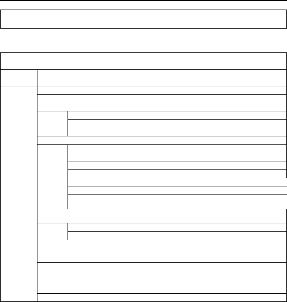
Data List
* The performance may vary with atmospheric temperature, humidity, and altitude.
Specifications Data
Product Name RMAX TypeII G UNIT,
Manufacturer Model L25
Performance Chemical Load Capacity* 16 kg
Practical Range (visual range) 150 m
Engine Type 2-cycle, horizontally opposed 2-cylinder
Cylinder Displacement 246 cc
Maximum Output 15.4 kW
Cooling
System Water-Cooled
Specified Coolant Mixture of dealer-specified coolant and water
Mixing ratio Dealer-specified ratio
Starting System Electric Starter
Fuel
Type Regular gasoline mixed with 2-cycle engine oil
Mixing ratio 50 parts gasoline to 1 part oil
Specified Oil Dealer-specified oil
Tank Capacity 6 liters
Electrical
Control
System
Name YACS-G
Warning Device Self Monitor, YACS Warning Light, GPS Indicator Light
Warnings Low Fuel Level, Excess Load, Radio Signal Interference, Low Voltage, GPS
Control Condition, Velocity Display, etc.
Radiowave Frequencies for
Flying 72.690, 72.730, 72.810, 72.850, 72.910, 72.950 MHz
Battery Onboard 12 V, 6.0 Ah, VRLA, leaded battery
Transmitter 9.6 V, 1.0 Ah, Ni-MH battery
Spark Plug Unmanned helicopter spark plug (Yamaha P/N 94702-00271)
(NGK P/N BR7HS-10)
Helicopter
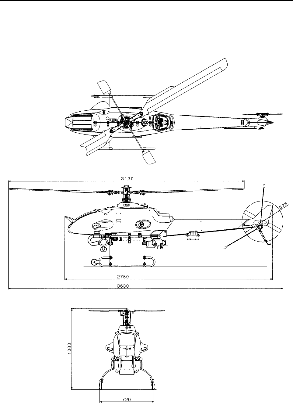
Dimensions
Main Rotor Diameter 3130 mm
Tail Rotor Diameter 535 mm
Overall Length / Overall Length
with Rotor 2750 mm/3630 mm
Overall Width 720 mm
Overall Height 1080 mm
RMAX.book Page 1 Tuesday, January 17, 2012 3:06 PM
Specifications
10-2
Dimensions
Unit: mm
RMAX.book Page 2 Tuesday, January 17, 2012 3:06 PM

Specifications
10-3
RMAX.book Page 3 Tuesday, January 17, 2012 3:06 PM

Inspection
Inspection Types and Descriptions ....................................... 11-1
Pre-Flight Inspection ........................................................................11-1
Post-flight Inspection .......................................................................11-2
30-Hour Inspection ...........................................................................11-2
Periodic Inspection ..........................................................................11-2
General Inspection ...........................................................................11-2
11
RMAX.book Page 1 Tuesday, January 17, 2012 3:06 PM

11-1
Inspection
The prescribed types of inspections are described
below.
•Pre-flight and post-flight inspections are to be
performed by the operator.
•For the 30-hour inspection, periodic inspection,
and general inspection, contact your dealer
(authorized service facility for Yamaha unmanned
helicopters for industrial applications).
What are Yamaha-authorized service facilities for
unmanned helicopters for industrial applications?
It is a service facility staffed by certified service
technicians for Yamaha industrial unmanned heli-
copters and equipped with the prescribed service
equipment.
Pre-Flight Inspection
Ensures that the helicopter and the auxiliary equip-
ment are free of problems before a flight.
See page 4-17 for details on the inspection.
Inspection Types and Descriptions
Have your dealer perform the 30-hour inspec-
tion, periodic inspection, general inspection,
and repairs. The performance of these
inspections by a person who is not a certified
unmanned helicopter service technician
could cause the helicopter to malfunction or
result in an accident.
Do not fly or perform an aerial application
without having a periodic inspection per-
formed every 100 hours of operation.
WARNING
TIP
RMAX.book Page 1 Tuesday, January 17, 2012 3:06 PM
Inspection
11-2
Post-flight Inspection
Ensures that the helicopter and the auxiliary equip-
ment are free of problems after a flight.
See page 6-1 for details on the inspection.
If a problem is detected, cancel the flight and
promptly contact your dealer.
Record the results of the inspection on the flight
log.
30-Hour Inspection
An inspection service performed after the delivery
of a new helicopter, when the hour meter indicates
a total of 30 hours of operation.
Periodic Inspection
An inspection service performed at a Yamaha-
specified dealer once for every 100 hours of opera-
tion indicated by the hour meter. The service
includes testing for durability and performance of
the helicopter and sprayer.
General Inspection
An inspection service to ensure the safety of the
helicopter when the hour meter shows a total of
500 or more hours of operation.
RMAX.book Page 2 Tuesday, January 17, 2012 3:06 PM

Inspection
11-3
RMAX.book Page 3 Tuesday, January 17, 2012 3:06 PM

Index
A
Air cleaner ......................................................... 2-3
Inspection ................................................... 6-3
Antenna ............................................................. 2-1
Inspection ................................................... 6-4
Azimuth Sensor ................................................. 2-1
B
Basic requirements ........................................... 1-2
Battery ............................................................... 2-3
Recharge .................................................... 7-1
Boom .......................................................... 4-1, 4-6
C
Carburetor ......................................................... 2-3
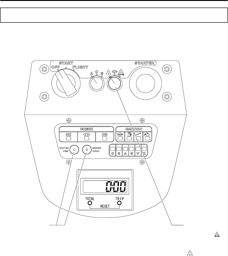
Check point indicator .................................. 2-2, 3-5
Chemical requirements ................................... 1-11
Chemical tank ............................................ 4-1, 4-6
Control panel ..................................................... 2-2
Coolant
Inspection ................................................. 4-20
Cushion tape ................................................... 4-22
D
Data list ........................................................... 10-1
Decompression lever ................................. 2-1, 5-5
E
Engine
Start ............................................................ 5-3
Stopping ................................................... 5-11
F
Failsafe actions ............................................... 3-12
Filter net ............................................................ 4-5
Flight indicator ............................................ 2-2, 3-5
Flight mode
Selecting ................................................... 4-13
Selector switch .................................. 2-2, 4-13
Flight requirements ........................................... 1-7
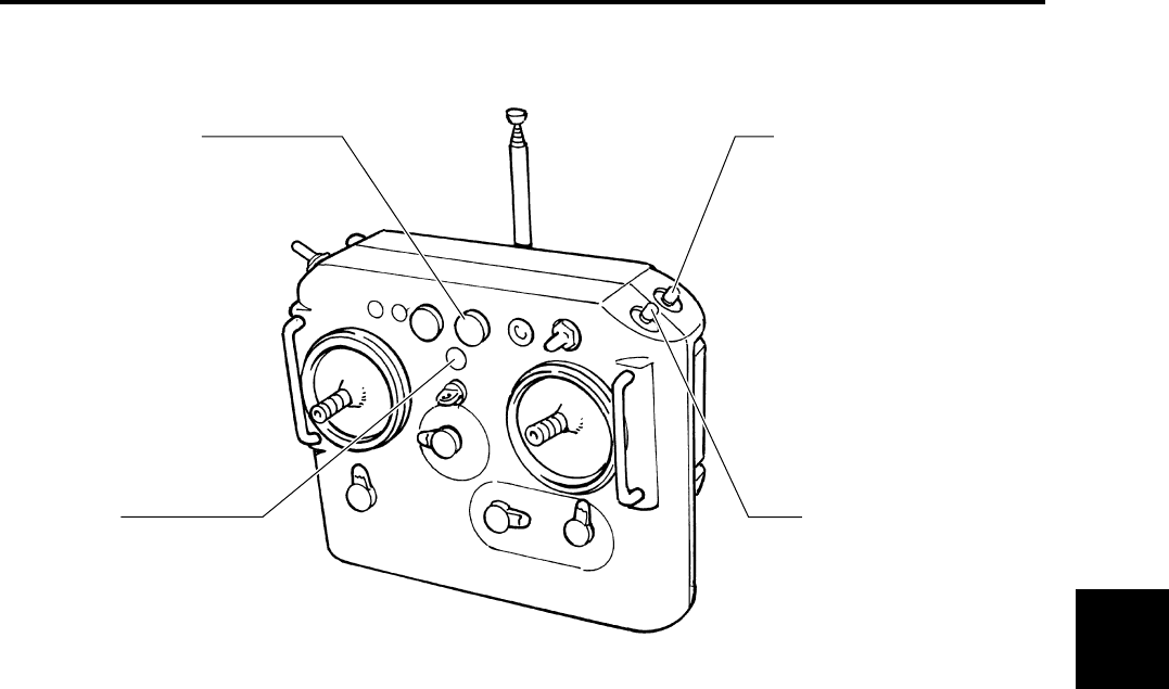
Flight transmitter ............................................... 2-4
Antenna .................................................... 4-18
Basic stick operation and helicopter
movement ............................................. 3-1
Recharging and replacing battery ............... 4-1
Basic trim lever operation and helicopter
movement ............................................. 3-2
Fuel
Inspection ................................................. 4-19
Preparing and refueling .............................. 4-4
Fuel filter ......................................................... 4-19
Fuel line ........................................................... 4-19
Fuel tank ........................................................... 2-3
Fuel tank cap .............................................. 2-1, 4-5
G
GPS
Antenna ...................................................... 2-1
Control switch ............................................. 3-3
Indicator light ....................................... 2-2, 3-9
Inspection ................................................. 4-26
Safety features and actions during
poor signal reception ........................... 3-15
Unit ............................................................. 2-1
Grip handle ........................................................ 4-7
H
Helicopter requirements .................................... 1-5
Hour meter ............................................... 2-2, 4-14
I
Inspection
30-hour inspection .................................... 11-2
General inspection .................................... 11-2
Periodic inspection .................................... 11-2
Post-flight Inspection .........................6-1, 11-2
Pre-flight .......................................... 4-17, 11-1
Intermediate transmission ............................... 4-21
L
Landing ........................................................... 5-11
Leaf ................................................................... 2-1
Linkage
Inspection ................................................. 4-23
M
Main rotor blade ................................................ 2-1
Inspection ................................................. 4-22
Main rotor blades
Installing and removing ............................. 4-15
Main switch ................................................ 2-2, 5-3
Malfunction area indicator .......................... 2-2, 3-6
Muffler ............................................................... 2-1
O
Oil
Inspection ................................................. 4-20
Operator requirements ...................................... 1-3
P
Payload inspection .......................................... 4-10
Plug cap ............................................................ 2-3
Post-Flight Cleaning and Servicing ................... 6-5
Product safety label locations ........................... 1-1
RMAXIX.fm Page 1 Wednesday, January 18, 2012 10:18 AM

R
Radiator ............................................................. 2-1
Radiator cap ............................................. 2-3, 4-21
Radio signal
Distance test ............................................. 4-25
Radio signal monitor ................................... 4-9
Radio signal interference inspection ................. 4-9
Recovery tank .......................................... 2-3, 4-20
Rubber hooks ........................................... 2-1, 4-16
Runner ....................................................... 2-1, 4-7
S
Self monitor ....................................... 2-2, 3-5, 4-24
Shutter pump cleaning switch ........................... 2-2
Side cover ......................................................... 2-1
Installing and removing ............................. 4-16
Slide servo ........................................................ 2-3
Inspection ................................................. 4-23
Slide servo thermo sensor ................................ 3-6
Spinner constant rotation switch ....................... 2-2
Spray
Spray switch ............................................... 3-4
Sprayer
Selector switch .................................... 2-2, 4-3
Spraying
Selecting and setting sprayer ..................... 4-3
Stabilizer blade .................................................. 2-1
Starter lever ................................................ 2-1, 5-5
Starter switch ............................................. 2-2, 5-6
Stone guard ............................................... 2-1, 4-6
Storage ............................................................. 8-1
T
Tail body ............................................................ 2-1
Tail cover ........................................................... 2-1
Tail rotor blade .................................................. 2-1
Inspection ................................................. 4-22
Tail rotor drive belt .......................................... 4-25
Takeoff .............................................................. 5-8
Transmission case .......................................... 4-21
Transmitter
Battery monitor light ......................... 3-11, 4-18
Inspection ................................................. 4-18
Transporting procedure ..................................... 4-6
Trim lever
Aileron ................................................. 2-4, 5-9
Elevator ............................................... 2-4, 5-9
Rudder ................................................. 2-4, 5-9
Throttle ................................................ 2-4, 5-5
Y
YACS
Control switch ............................................. 3-3
Warning light ........................................ 2-2, 3-7
RMAX.book Page 2 Tuesday, January 17, 2012 3:06 PM

Please read this manual before using the product.
UNIT,
LIQUID SPRAYER
OPERATION MANUAL
LIQUID SPRAYER
OPERATION MANUAL
UNMANNED HELICOPTER FOR INDUSTRIAL APPLICATIONS
UNMANNED HELICOPTER FOR INDUSTRIAL APPLICATIONS
R-max.book Page 1 Tuesday, January 17, 2012 3:08 PM
Foreword
Thank you for using the liquid sprayer for the RMAX TypeII G Unit, unmanned helicopter for
industrial applications.
This operation manual describes the proper operating procedures as well as inspection and
servicing methods for the liquid sprayer for the RMAX TypeII G Unit, helicopter. Before using
this product, please be sure to read this operation manual, along with the separate opera-
tion manual for the RMAX TypeII G Unit, helicopter, and thoroughly understand the informa-
tion contained therein.
In this manual, the warning notes, which are necessary for safe and proper operation of this
product, are categorized and shown as follows. Please make sure to observe these instruc-
tions, as they all contain important information.
●After you have read this operation manual, keep it within easy access near the product.
●If you have lost this operation manual, contact your dealer to request another copy.
●Contact your dealer if you have any questions or comments regarding the contents of
this operation manual.
●Some diagrams and contents in this manual may differ from the actual device, due to
specification changes, etc.
This indicates that improper operation will
cause imminent danger, which could lead to
serious injury or death.
This indicates that improper operation could
lead to minor and serious injuries or death.
Indicates that improper operation could
cause property damage.
Indicates proper operating procedure and
tips on inspection and maintenance.
Indicates a prohibited action.
The specific prohibited action is illus-
trated near the symbol.
DANGER
WARNING
NOTICE
TIP
R-max.book Page 2 Tuesday, January 17, 2012 3:08 PM

1
2
3
4
5
6
7
8
Table of Contents
Safety Precautions
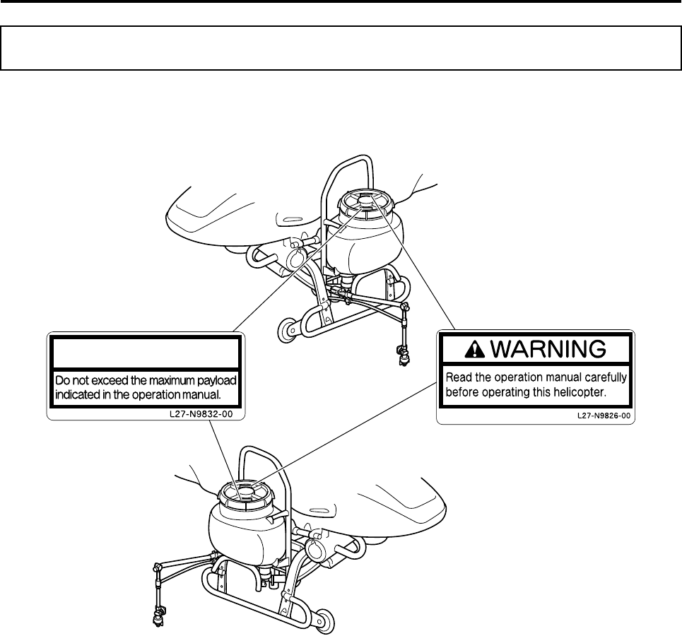
Product Safety Label Locations ............................................................... 1-1
Requirement ............................................................................................... 1-2
Spraying Precautions ................................................................................ 1-5
Usage Precautions..................................................................................... 1-9
Part Names
Part Names ................................................................................................. 2-1
Mounting and Removing the Sprayer
Mounting and Removing the Sprayer ...................................................... 3-1
Spraying Method
Relevant Switches ..................................................................................... 4-1
Using the Sprayer ...................................................................................... 4-3
Spray Specifications Settings .................................................................. 4-7
Cleaning and Inspections
Cleaning the Sprayer ................................................................................. 5-1
Inspecting and Cleaning Various Parts ................................................... 5-3
Troubleshooting
Troubleshooting......................................................................................... 6-1
Specifications
Specifications Data.................................................................................... 7-1
Product Inspection
About Inspections...................................................................................... 8-2
R-max.book Page 1 Tuesday, January 17, 2012 3:08 PM
1-1
Safety Precautions
Before using the device, please read and understand the affixed product safety labels thoroughly.
Product Safety Label Locations
NOTICE
R-max.book Page 1 Tuesday, January 17, 2012 3:08 PM
Safety Precautions
1-2
Basic requirements
Requirement
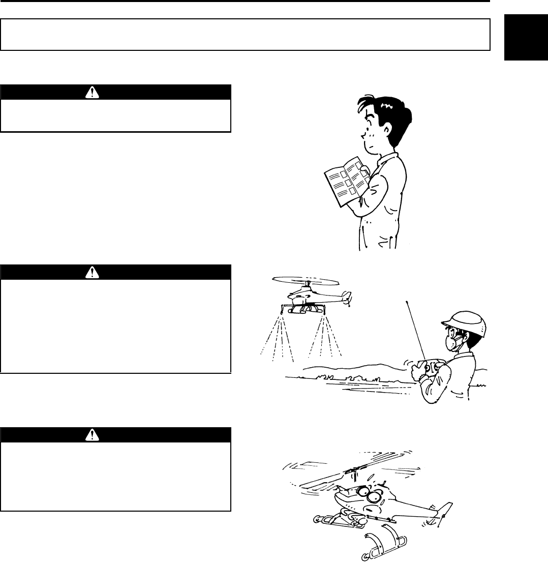
To ensure safe use, please make sure to read
the operation manual thoroughly before use.
WARNING
This liquid sprayer for the unmanned heli-
copter for industrial applications has been
manufactured for the purpose of aerial appli-
cation of agricultural chemicals, fertilizers,
and seeds. Do not use it for other applica-
tions. It could also cause unexpected acci-
dents.
WARNING
Do not modify the helicopter or the auxiliary
devices. Do not use parts other than genuine
parts. Any modification of the helicopter or
use of non-genuine parts may cause unex-
pected accidents.
WARNING
1
2
3
4
5
6
7
8
R-max.book Page 2 Tuesday, January 17, 2012 3:08 PM
Safety Precautions
1-3
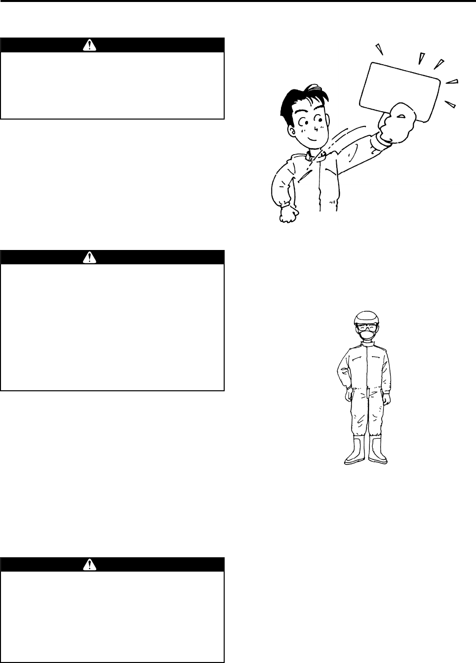
Operator requirements
Observe the following clothing requirements:
●Wear a helmet.
●Wear goggles and a particle mask.
●Wear long-sleeved clothing with secure buttons
and fasteners.
●Wear slip-proof shoes that are easy to walk with.
●Do not wear objects that could obstruct vision
when there is wind, or adversely affect operation
(especially towels and gloves).
Flying this helicopter requires a high level of
skill.
The helicopter should be operated only by a
person who possesses an appropriate
license.
WARNING
Certificate of
Authorization
Make sure to wear a helmet during flight. To
perform an aerial application, make sure to
wear clothing that is appropriate for the oper-
ation. Performing a flight and an aerial appli-
cation in clothing that is not appropriate for
the task could cause loss of visibility, maneu-
vering error, or cause your foot to slip, result-
ing in unexpected accidents. Furthermore, it
could harm your health through exposure to
agricultural chemicals.
WARNING
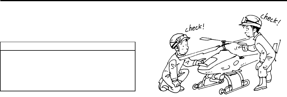
A minimum of 3 people is required for an
aerial application: a navigator who has been
briefed on the aerial application procedure,
an assistant who readies, mixes, and sup-
plies agricultural chemicals, and an operator.
Beware that an understaffed operation could
lead to an accident.
WARNING
R-max.book Page 3 Tuesday, January 17, 2012 3:08 PM
Safety Precautions
1-4
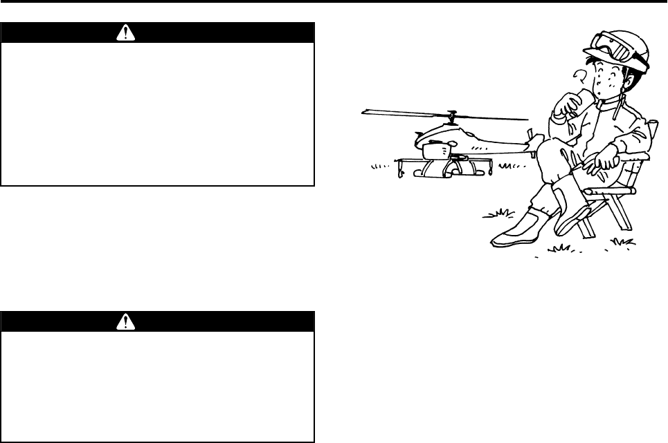
The operation of an unmanned helicopter
involves considerable mental fatigue. The
operator should not fly the helicopter contin-
uously for more than one hour, but should
take a rest every hour. Prolonged continuous
flight operation could cause the operator to
lose concentration and could lead to an acci-
dent.
WARNING
Do not fly the helicopter after drinking alco-
hol or taking a cold medicine, or if you are in
poor physical condition. Flying the helicopter
in poor physical condition could cause loss
of concentration, and could lead to an acci-
dent.
WARNING
R-max.book Page 4 Tuesday, January 17, 2012 3:08 PM
Safety Precautions
1-5
When operating an unmanned helicopter for the purpose of spraying agricultural chemicals, ensure safe oper-
ation, as well as the safety of humans, animals, agricultural products, and the environment during aerial appli-
cation.
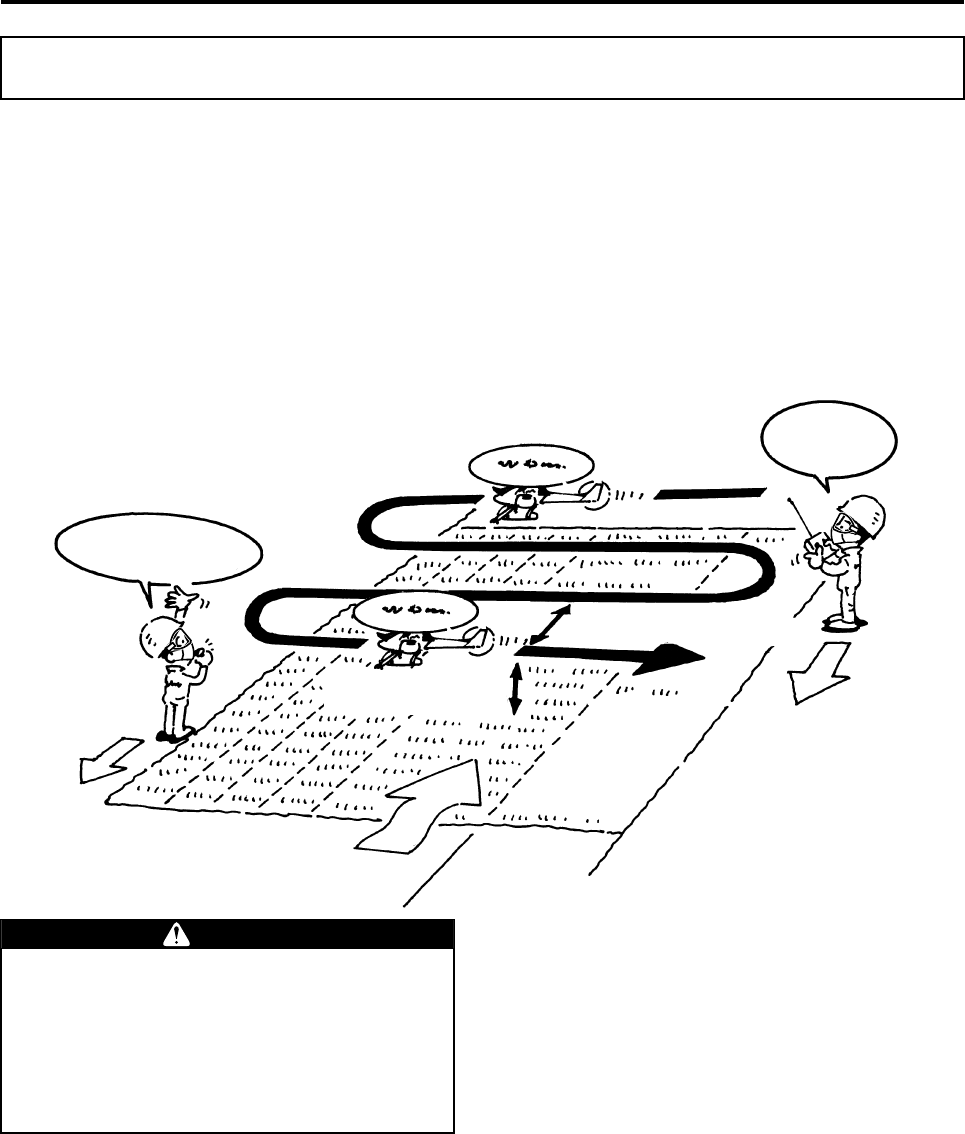
General Flight Pattern for Aerial Application
Example: Disease and pest control of a rice paddy
• Flight altitude: 3 to 4 m
• Flying speed: 10 to 20 km/h
• Flying interval: 5 or 7.5 m
• Wind velocity: 3 m/s maximum
Spraying Precautions
Affirmative!
Just passed 10 meters,
and 5 meters
Flying speed between
10 and 20 km/h
Flying height between
3 and 4 meters
Flying interval 5 or 7.5 meters
Wind
When performing tasks such as refueling,
never approach (or allow others to approach)
within 20 m of the helicopter until the main
rotor has come to a complete stop and the
engine has stopped. Entering within 20 m of
the helicopter could cause a serious acci-
dent.
DANGER
R-max.book Page 5 Tuesday, January 17, 2012 3:08 PM
Safety Precautions
1-6
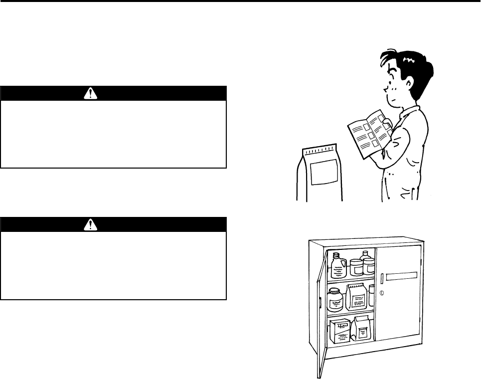
Using Registered Agricultural Chemicals
Use nationally registered agricultural chemicals,
and use them properly by reading the usage
instructions and precautions included in the manual
for each respective chemical.
Do not use agricultural chemicals other than
those registered. Failure to do so could
expose animals, plants, or people to agricul-
tural chemicals for which the operator will be
held socially responsible.
WARNING
Control and handle agricultural chemicals
strictly in accordance with their manuals.
Negligent control and improper handling of
agricultural chemicals could lead to chemical
pollution or health hazards.
WARNING
R-max.book Page 6 Tuesday, January 17, 2012 3:08 PM
Safety Precautions
1-7
Spray Chemical
Since the agricultural chemical is diluted at a low
dilution rate, make sure to observe the following:
(1) Agricultural Chemical
●Use nationally registered agricultural chemicals.
●In low-volume liquid spraying, the characteristics
of the agricultural chemical can easily change
when mixed with other agricultural chemicals,
and may produce solids or turn to a gum-like
state. When mixing, use agricultural chemicals
that have been checked in advance for physio-
chemical change, compatibility with the sprayer,
mixture toxicity, etc.
●Spreading agents (surface active agents) cannot
be added.
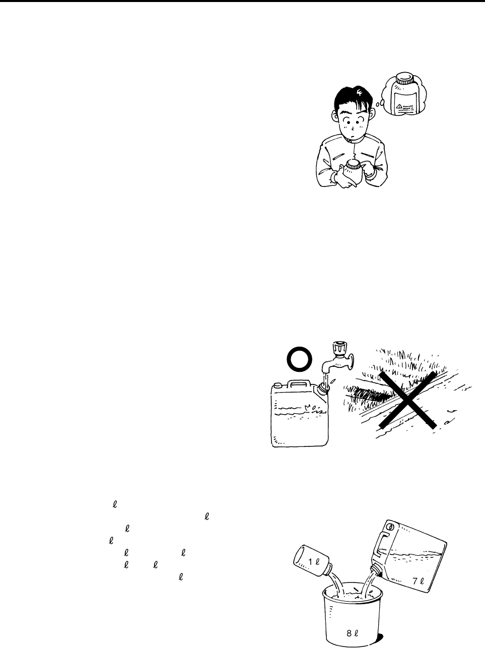
(2) Dilution Water
For dilution water, make sure to use tap water. Do
not use agricultural water, as this could lead to
debris clogging or characteristic change in the agri-
cultural chemical.
(3) Dilution Rate
For example, to make 8 of spray solution of an
agricultural chemical diluted to 8x, dilute 1 of
agricultural chemical with 7 of tap water (dilution
water). This will make 8 of spray solution.
Agricultural chemical: 8 × 1/8 = 1
Tap water: 8 - 1 (agricultural
chemical) = 7
Since flowable and water-dispersible chemicals can
easily precipitate, combine and mix them well just
before aerial application flight.
Label
Agricultural
Water
Tap Water
Chemical
Spray Solution
Tap Water
R-max.book Page 7 Tuesday, January 17, 2012 3:08 PM
Safety Precautions
1-8
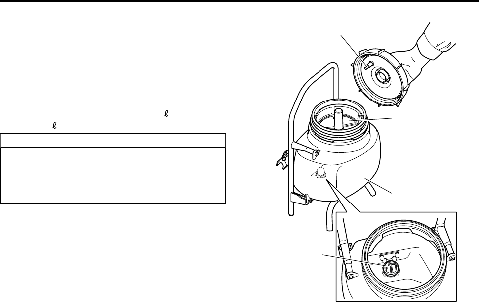
Pouring the Spray Solution
●Check the inside of the chemical tank (into which
the solution will be poured), the check valve, the
strainer section, and the filter for any debris or
sediments. If you find any debris or sediments,
make sure to remove them before pouring the
solution.
●Keep the chemical tank load to 8 or less per
side (16 combined for left and right tanks).
●For higher altitudes and temperatures,
decrease the load.
●For information on load capacity, see the
operation manual for the helicopter.
TIP
Chemical Tank
Strainer
Check Valve
Filter in the
Chemical Tank
R-max.book Page 8 Tuesday, January 17, 2012 3:08 PM
Safety Precautions
1-9
Stop the engine when replenishing the chemical.
When replenishing the chemical, make sure to stop
the engine. If this task takes longer than one
minute, turn OFF the main switch on the helicopter.
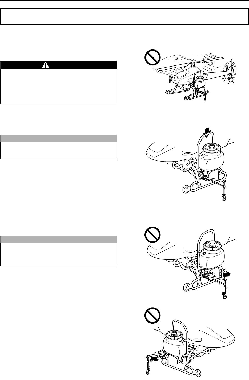
Securely mount the chemical tanks.
Prior to the flight, check that both chemical tanks
are securely mounted.
Do not apply excessive force on the boom.
When performing tasks such as replenishing the
chemical, use caution not to trip on the boom.
Usage Precautions
Never approach (or allow others to approach)
within 20 m of the helicopter until the main
rotor has come to a complete stop and the
engine has stopped. Entering within 20 m of
the helicopter could cause a serious accident.
DANGER
If the chemical tanks are not securely
mounted, they could come off during flight.
NOTICE
If an excessive force is applied against the
folding direction of the boom, it could
become damaged.
NOTICE
R-max.book Page 9 Tuesday, January 17, 2012 3:08 PM
2-1
Part Names
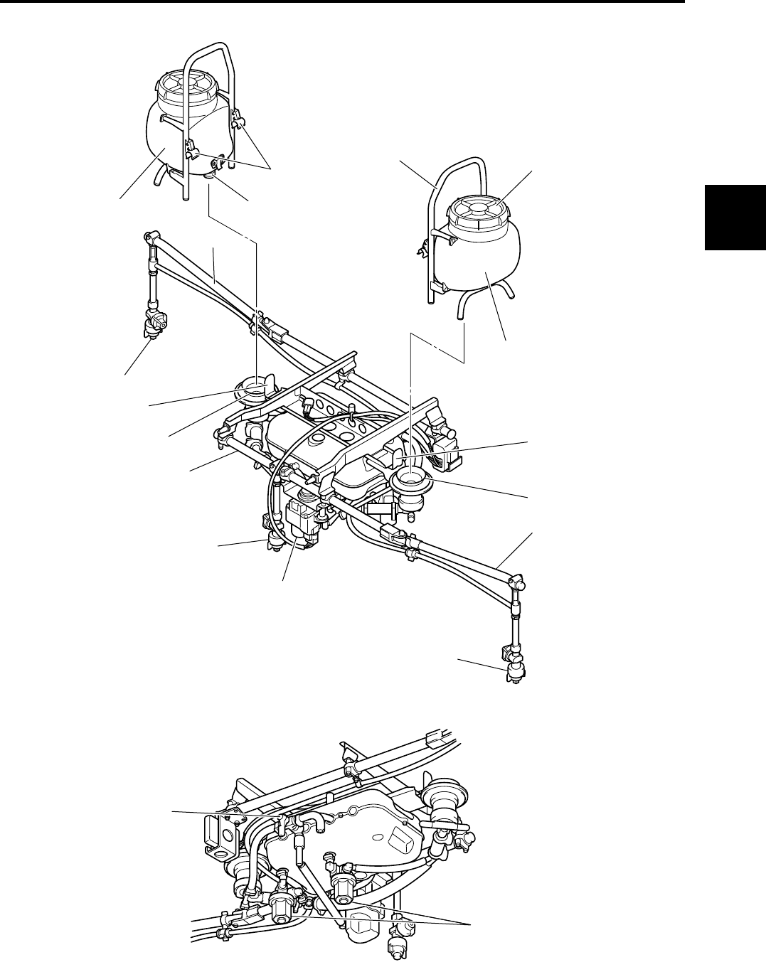
Part Names
Right and Left Nozzles
Boom
Chemical Tank Joint
Boom
Right and Left Nozzles
Nozzle Switching Motor
Chemical Tank Joint
Boom
Center Nozzle
Bracket
Bracket
Tank Cap
Handle
Joint
Bracket
Chemical Tank
Chemical Tank
Filter Cap
Three-way Cock
1
2
3
4
5
6
7
8
R-max.book Page 1 Tuesday, January 17, 2012 3:08 PM
3-1
Mounting and Removing the Sprayer
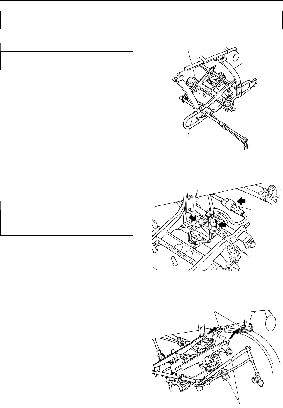
1Position the sprayer under the frame.
2Of the three connectors running from the frame,
connect the 2-pole connectors to the sprayer
pump’s power connectors, and the 3-pole con-
nector to the power connector of the nozzle
switching motor.
3Insert the dampers of the sprayer (2 locations)
into the mounting holes (2 locations) on the
frame.
Mounting and Removing the Sprayer
Extend the sprayer boom, and slide horizon-
tally from between the leaves.
TIP Sprayer
Leaf
Leaf
If necessary, apply the dealer-specified
grease onto the O-rings of the joints on the
bottom of the chemical tanks.
TIP
3-pole connector
2-pole connector
Mounting Holes
Dampers
R-max.book Page 1 Tuesday, January 17, 2012 3:08 PM
Mounting and Removing the Sprayer
3-2
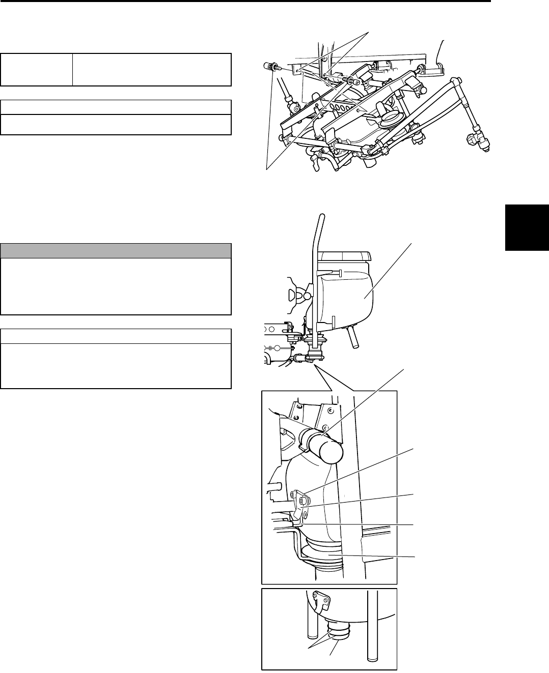
4Lift the rear of the sprayer, and fasten by insert-
ing bolts and washers through the right and left
bracket holes on the frame.
5Securely mount the left and right chemical tanks
by fitting the sprayer’s brackets into the mounting
stays on the chemical tanks.
6To remove the sprayer, follow the mounting pro-
cedure in reverse order.
Tightening
Torque 3 to 4.5 N·m (0.3 to 0.45 kg·m)
Use a 4 mm hex wrench.
TIP
Bracket Holes
Bolts/Washers
If the chemical tanks are not mounted prop-
erly, it could cause the helicopter to shake,
the chemical to leak, or the chemical tank to
fall off the helicopter.
If necessary, apply dedicated grease
(Yamaha Grease B) onto the O-rings on the
bottom of the chemical tanks.
NOTICE
TIP
Chemical Tank
(set in securely)
Guide
Valve Seal
(set in securely)
Mounting Stay
Bracket
O-Rings
Joint
1
2
3
4
5
6
7
8
R-max.book Page 2 Tuesday, January 17, 2012 3:08 PM
4-1
Spraying Method
Helicopter Control Panel
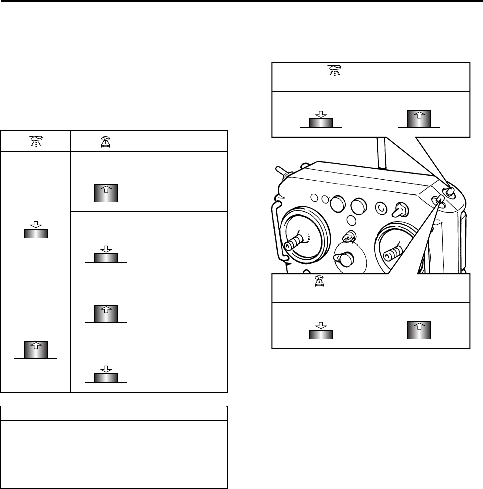
Relevant Switches
Sprayer Selector Switch
To use the speed-dependent
function, switch to “”.
When not using the speed-
dependent function, switch t
o
“”.
Shutter Pump Cleaning Switch
Spinner Constant Rotation Switch
Used for cleaning the pump.
See “Cleaning the Sprayer” on
page 5-1.
R-max.book Page 1 Tuesday, January 17, 2012 3:08 PM
Spraying Method
4-2
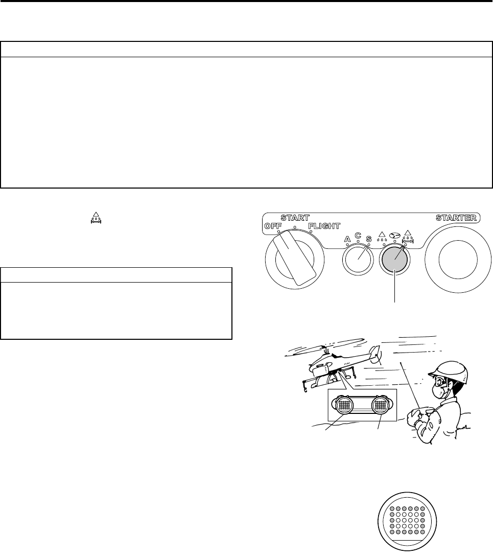
Flight Transmitter
Spray Volume Adjuster
(for Liquid)
This adjusts the amount of liq-
uid discharged.
See “Spray Specifications
Settings” on page 4-7.
Power Switch
This is the power switch
for the transmitter.
Spray Switch
This is an ON/OFF switch for the
spray pump.
See “Using the Sprayer” on page 4-3.
Spray Volume Switch
This switches between the left/
right nozzles and the center
nozzle.
See “Using the Sprayer” on
page 4-5.
1
2
3
4
5
6
7
8
R-max.book Page 2 Tuesday, January 17, 2012 3:08 PM
Spraying Method
4-3
Spraying with Flight Transmitter
1Switch the sprayer selector switch on the flight con-
trol panel to “”.
To use the speed-dependent function, switch to
“”.
2Set the spray volume adjuster and the spray noz-
zle settings according to “Spray Specifications
Settings” on page 4-7.
3Tu r n O N (“in” position) the spray switch (the ON/
OFF switch) on the flight transmitter to actuate
the spray pump. Press again (“out” position) to
stop.
4Check the spraying condition. Check if the spray-
ing condition from each nozzle is good.
Using the Sprayer
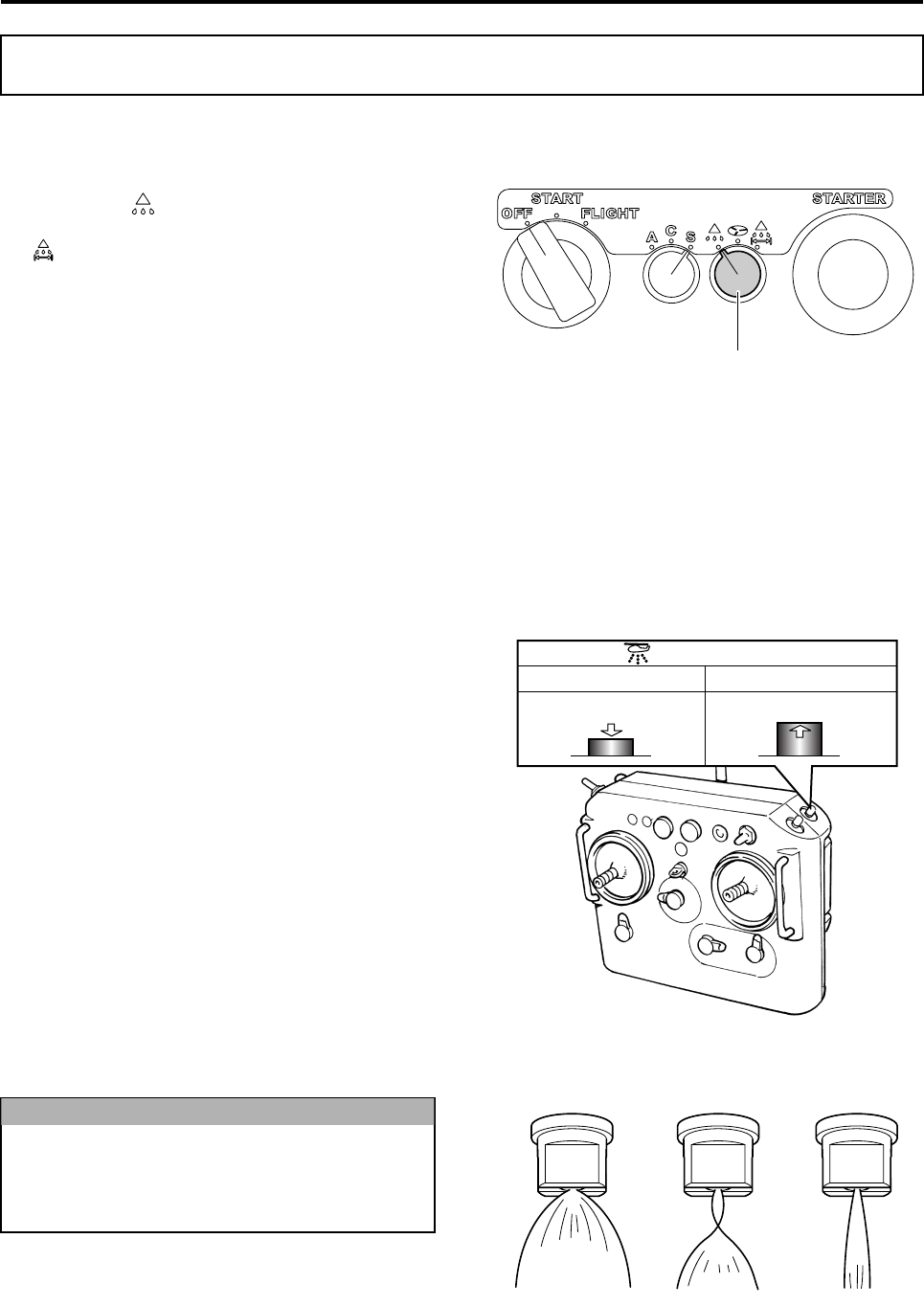
Sprayer Selector Switch
Push
ON (to operate) OFF (to stop)
Release
Spray Switch
Do not keep the pump running for more than
10 seconds with nothing spraying out from
the nozzle, or on an empty tank. The pump
could burn out.
NOTICE
Illustration of Spraying Conditions
Good Poor Poor
R-max.book Page 3 Tuesday, January 17, 2012 3:08 PM
Spraying Method
4-4
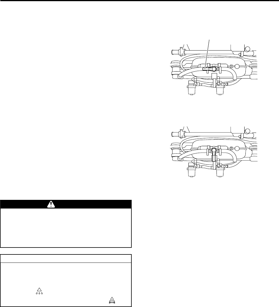
How to Release Air Pockets
When the chemical tanks are plugged/unplugged,
or when the chemical is sprayed until the chemical
tanks are empty, air pockets will get entrained
inside the sprayer piping, causing the spraying con-
dition to deteriorate.
With the chemical tanks set in place, if the air pock-
ets are not completely released by discharging from
the nozzles, turn OFF the sprayer switch, and
release the air pockets as follows:
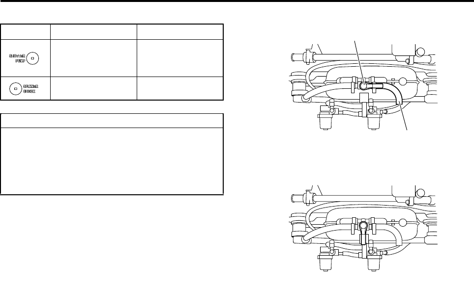
1Facing the rear of the helicopter, turn the three-
way cock handle on the rear of the sprayer so
that it points to your left.
2Turn ON the sprayer switch, and run the spray
pump for 5 to 7 seconds.
3Point down the three-way cock to the spraying
position, and verify that the discharge condition
from the nozzle is good.
Air Releasing Position (pointing left)
Three-way Cock Handle
Spraying Position (pointing down)
When releasing air pockets, do not perform
the task (or allow others to approach the heli-
copter) until the main rotor has stopped
rotating completely and the engine has
stopped.
If you are using the speed-dependent func-
tion and need to release air after receiving
the GPS signal, set the sprayer selector
switch to “”. After releasing air pockets,
return the sprayer selector switch to “”.
DANGER
TIP
R-max.book Page 4 Tuesday, January 17, 2012 3:08 PM
Spraying Method
4-5
Switching Between Nozzles
Set the spray volume switch on the flight transmitter
to “1” (“out” position) to discharge from the right and
left nozzles. Set it to “1/2” (“in” position) to dis-
charge from the center nozzle.
To switch between nozzles, turn OFF the spray
switch, and perform the task after the spray pump
has stopped.
Nozzle
ON
(to operate)
“1”
Sprays from left
and right nozzles
“1/2”
Sprays from cen-
ter nozzle
OFF
(to stop)
“1”
Stops spray pump
“1/2”
If you switch between nozzles with the spray
volume switch while the spray switch is in
the ON state, the spray pump will stop for
approximately one second, during which the
nozzle switching motor runs.
Push
Release
Push
Release
Release
Push
TIP
Push
ON (to operate) OFF (to stop)
Release
Push
“1/2” (Center nozzle) “
1
”
(Left and right nozzles)
Release
Spray Volume Switch
Spray Switch
R-max.book Page 5 Tuesday, January 17, 2012 3:08 PM
Spraying Method
4-6
Using the Speed-Dependent Function
1Switch the sprayer selector switch on the flight
control panel to “ ”.
2Set the spray volume adjuster and the spray noz-
zle settings according to “Spray Specifications
Settings” on page 4-7.
If the GPS signal reception is poor (the outer GPS indicator lights are ON), the speed-dependent function
does not work, and the chemical is discharged at a constant rate set by the spray volume adjuster on the flight
transmitter.
During a GPS-controlled flight, if the GPS signal reception worsens (GPS indicator lights cycles a pattern
“outer lights ON > inner lights ON > OFF”), the speed-dependent function does not work, and the chemical is
discharged at a constant rate set by the spray volume adjuster on the flight transmitter.
In this case, immediately turn OFF the GPS control switch according to the operation manual for the helicop-
ter.
●The speed-dependent function can be used only when all of the following three conditions are
met:
• Low-volume liquid spraying at 7.5m spray width, 8L/ha
• Left and right nozzles are selected
• The GPS signal reception is good (i.e. the outer GPS indicator lights are ON)
The state of the flight mode selector switch on the helicopter and the GPS control switch on
the flight transmitter are irrelevant.
●When the center nozzle is used, the speed-dependent function does not work, and discharging is
done in proportion to a constant volume set by the spray volume adjuster on the flight transmit-
ter.
TIP
If the flight velocity exceeds 20km/h, only the
outer lights of the YACS warning lights illumi-
nate. If this happens, drop the flight velocity
to 20km/h or less.
TIP
Sprayer Selector Switch
GPS
Indicator Light
YACS
Warning Light
Only the outer lights
of the YACS warning
lights illuminate
R-max_4.fm Page 6 Wednesday, January 18, 2012 10:16 AM
Spraying Method
4-7
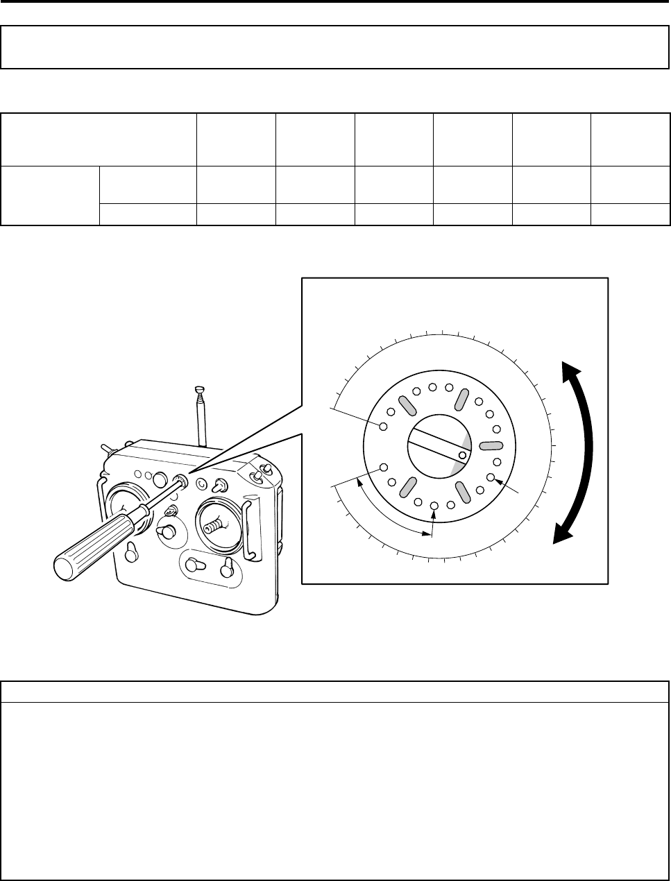
Set the spray volume adjuster and spray nozzles according to the chemical to be used.
Spray Specifications Settings
Spray Specifications
Spray
Volume
(L/ha)
Spray
Width
(m)
Nozzle
Color
Number of
Nozzles
Volume
Position Remarks
Low-Volume
Liquid Spraying
Right and Left
Nozzles 8 7.5 Yellow 2 Level 24 Standard
Center Nozzle 8 3.75 Yellow 1 (has groove) Level 24 Standard
0
(b)
(a)
24
32
40
Spray Volume Adjuster
●The adjuster covers a range of volumes, allowing you adjust the spray volume according to the
chemical used.
●When you turn all the way towards the (b) direction, and start turning back towards the (a) direc-
tion, the first notch you reach is Level 1.
●Turning in the (a) direction increases the spray volume, and turning in the (b) direction decreases
the spray volume.
●Levels between 32 to 40 use maximum current, therefore, do not use continuously.
●After adjusting the volume, make sure to put the rubber cover back on.
●The spray specifications settings above are only to be used as a guideline. Before the actual
spraying task, make sure to check the spray volume for the chemical you are using.
TIP
R-max_4.fm Page 7 Wednesday, January 18, 2012 10:16 AM
5-1
Cleaning and Inspections
Cleaning the Spray Pump
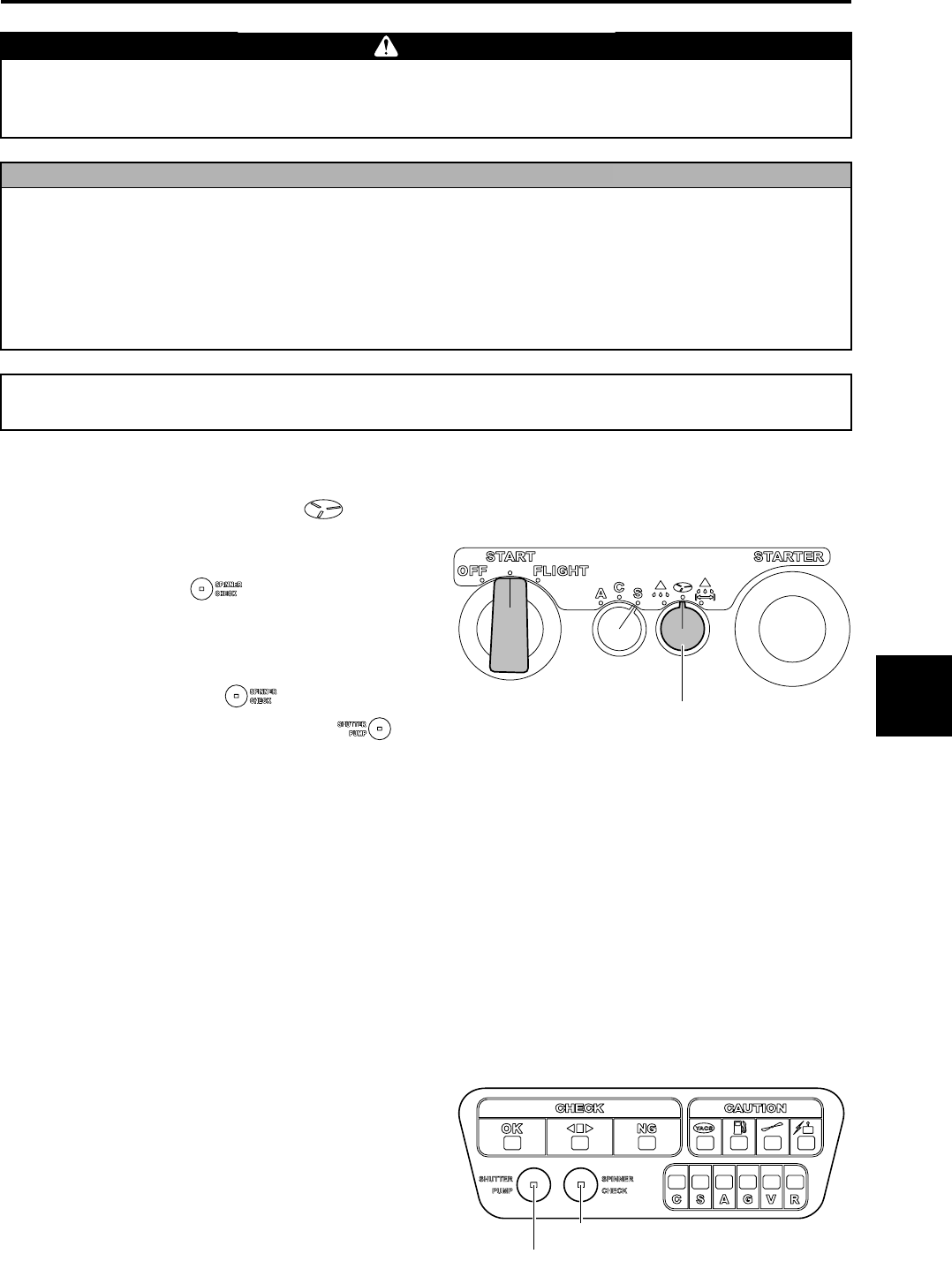
1Turn the sprayer selector switch to “ ”.
2Mount the chemical tank filled with tap water,
and turn the main switch of the helicopter to
“START”. Press the “ ” switch on the con-
trol panel to clean the inside of the sprayer pip-
ing.
3To switch between the right/left nozzles and the
center nozzle, press the “ ” switch to tem-
porarily stop the pump, then use the “ ”
switch.
4Drain the chemical inside the spray piping
through the drain pipe, by pointing the three-way
cock handle to the right, thereby actuating the
spray pump.
5After draining out the chemical, point the three-
way cock handle to the spraying position (down).
6Remove the filter and nozzles, and wash them
with tap water. (See pages 5-3 and 5-4.)
7If you want to wash the sprayer thoroughly,
remove the sprayer and wash with tap water.
When doing this, use caution to keep the 2-pole
and 3-pole connecters from getting wet. (See
page 3-1.)
Control and handle the agricultural chemicals strictly in accordance with their manuals. Negligent
control and improper handling of agricultural chemicals could lead to chemical pollution or health
hazards.
WARNING
●Clean the sprayer after every spraying work, as the spraying performance could deteriorate due
chemicals solidifying onto the sprayer.
●Use a drain pipe to collect the leftover chemical and cleaning solutions from cleaning into a con-
tainer, and dispose it according to the operation manual for the chemical.
●During winter seasons, the pump or the filter cap may become damaged by frozen liquids. There-
fore, for long-term storage during winter seasons, drain the leftover chemical and remove the fil-
ter cap.
NOTICE
Cleaning the Sprayer
Sprayer Selector Switch
Shutter Pump Cleaning Switch
Spinner Constant Rotation Switch
1
2
3
4
5
6
7
8
R-max_5.fm Page 1 Wednesday, January 18, 2012 10:16 AM
Cleaning and Inspections
5-2
Press once Press again
Switches to right
and left nozzles or
center nozzle
Switches to right
and left nozzles or
center nozzle
Operates pump Stops pump
●Operating the pump for more than one
minute could drain the battery.
●During cleaning, do not use the flight
transmitter to switch between right/left
nozzles and center nozzle.
TIP
Drain Pipe
Three-way Cock Handle
Chemical Draining Position (pointing right)
Spraying Position (pointing down)
R-max.book Page 2 Tuesday, January 17, 2012 3:08 PM
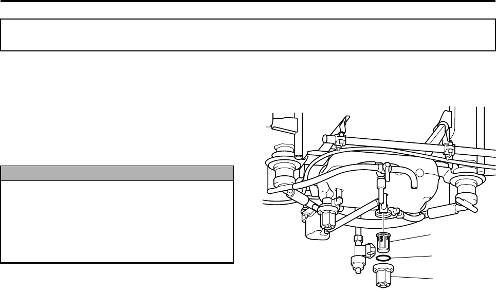
Cleaning and Inspections
5-3
Filter Inspection and Cleaning
1Turn OFF the main switch of the helicopter.
2Remove the left and right chemical tanks.
3Remove the filter cap, and visually inspect if the
filter inside is clogged.
If clogged, wash it with tap water.
Inspecting and Cleaning Various Parts
●If a tear exists in the filter, replace it, as it
could cause the spray pump or the nozzles
to become clogged.
●When putting on the filter cap, securely
fasten the O-ring to prevent air entrain-
ment and liquid leakage.
NOTICE
Filter
O-Ring
Filter Cap
R-max.book Page 3 Tuesday, January 17, 2012 3:08 PM
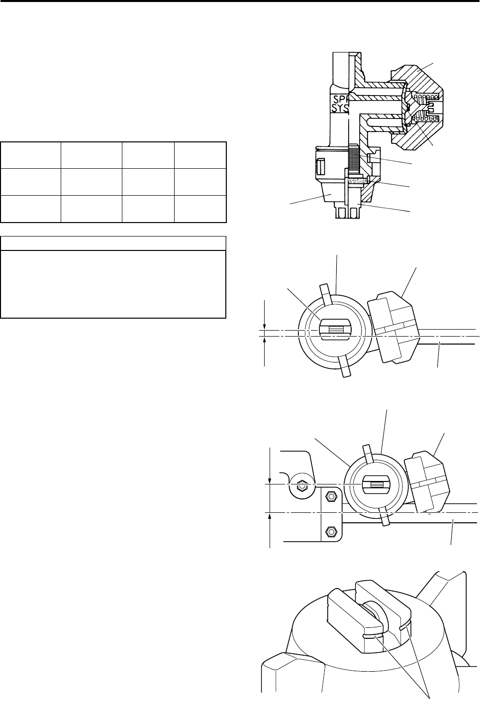
Cleaning and Inspections
5-4
Nozzle Inspection and Cleaning
1Loosen the nozzle caps and end caps for the
left, right and center nozzles. Remove seat 2,
strainer 2, seat 1, and nozzle, and check them
for damage and wear.
If clogged, wash it with tap water.
2Reattach the nozzles so that the nozzle spraying
hole and the boom are parallel.
Nozzle
Number
Nozzle
Cap Color
End Cap
Color
Right and
Left Nozzles
XR TEEJET
11002 VS Yellow Black
Center Noz-
zle
XR TEEJET
8002 VS Red Blue
●When reattaching the nozzles, do not con-
fuse the left/right nozzles and the center
nozzle.
●Only the center nozzle has a groove along
its outer perimeter.
TIP
Nozzle
Cap
Strainer 2
Seat 2
End Cap
Seat 1
Nozzle
Red Nozzle Cap
Black End Cap
Nozzle
Boom
Parallel
Right and Left Nozzles
Nozzle
Red Nozzle Cap
Blue End Cap
Parallel
Boom
Center Nozzle
Only the center nozzle has a groove along its outer perimeter
R-max.book Page 4 Tuesday, January 17, 2012 3:08 PM
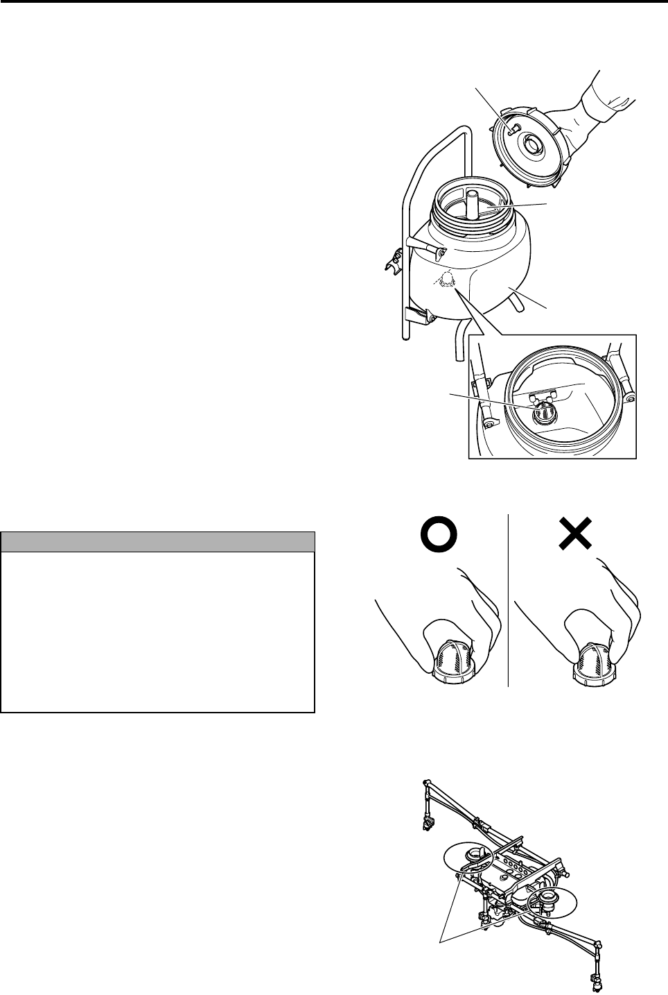
Cleaning and Inspections
5-5
Chemical Tank Inspection and Cleaning
1Inspect the check valve on the chemical tank cap
to check if it is clogged.
2Remove the strainer and visually check if it is
clogged.
If clogged, wash it with tap water.
3Remove the filter by turning it counterclockwise,
and visually check if it is clogged.
If clogged, wash it with tap water.
Chemical Tank Joint Inspection and Cleaning
Visually check if the valve seal part of the chemical
tank joint is clogged.
If clogged, wash it with tap water.
Strainer
Chemical Tank
Check Valve
Filter in the
Chemical Tank
●If a tear exists in the strainer or filter,
replace it, as it could cause the spray
pump or the nozzles to become clogged.
●When using a chemical that precipitates
quickly, frequently remove and clean the
strainer and filter.
●When removing the filter, do not pull it by
the mesh part, as this could damage the
filter.
NOTICE
Chemical Tank Joint
R-max.book Page 5 Tuesday, January 17, 2012 3:08 PM
6-1
Troubleshooting
The problems listed here can be handled primarily
by the user.
Problems or causes that are not listed here are
handled by your dealer. If such problems occur,
cancel the flight and contact your dealer to have the
helicopter inspected and repaired.
The spray pump does not operate
The spray pump operates, but nothing is discharged
●Make sure to follow the instructions given
in the “User Action” column, and do not
take any actions that are not documented.
●If you have any questions, be sure to con-
tact your dealer. If an inspection, adjust-
ment, or part replacement is performed by
a person who does not possess the kno-
whow and proficiency to service the heli-
copter, it could lead to a serious accident.
WARNING
Main Cause User Action Remarks
1Poor connection with the power connector of
the spray pump.
Securely connect the power connector of the
spray pump. See page 3-1.
2 The nozzles are being switched.
If the nozzles are switched while the spray
pump is running, the nozzle switching motor
runs for approximately one second, during
which the spray pump automatically stops. The
spray pump will resume automatically.
See page 4-5.
3 The onboard battery is faulty. Recharge the battery with a dedicated
recharger, or replace it.
See the opera-
tion manual for
the helicopter
4 Deterioration in the spray pump performance. Quickly cancel the flight, and request a repair
by your dealer.
5 A break in the wiring. Quickly cancel the flight, and request a repair
by your dealer.
6 A blown fuse. Quickly cancel the flight, and request a repair
by your dealer.
Main Cause User Action Remarks
1 Air pockets have not been sufficiently released. Release air pockets by opening the three-way
cock. See page 4-4.
2 Clogged chemical tank joint. Clean the chemical tank joint. See page 5-5.
3 Clogged filter. Clean the filter. See page 5-3.
4 Clogged nozzle. Clean the nozzle. See page 5-4.
5 Wrong nozzle attached. Attach the correct parts. See page 5-4.
6 Clogged check valve on the chemical tank cap. Clean the check valve. See page 5-5.
7 Deterioration in the spray pump performance. Quickly cancel the flight, and request a repair
by your dealer.
R-max.book Page 1 Tuesday, January 17, 2012 3:08 PM
Troubleshooting
6-2
The discharge volume is low / The spraying angle is narrow / The
chemical is not getting atomized / The chemical drips in large droplets
The chemical is leaking.
Nozzles do not switch.
The speed-dependent function is non-functional.
Main Cause User Action Remarks
1 Incompatible agricultural chemical.
Choose a different agricultural chemical.
If it is a mixture of two agricultural chemicals,
revise the chemicals that are mixed.
2 Poorly adjusted spray volume. Readjust the spray volume on the flight trans-
mitter. See page 4-7.
3 Clogged nozzle. Clean the nozzle. See page 5-4.
4 Entrained air pockets in the spray pump. Release air pockets by opening the three-way
cock. See page 4-4.
5 Clogged spray pump
Clean the spray pump.
If the problem persists, request a repair by your
dealer.
See page 5-1.
6 Poorly sealed seat 2. Clean seat 2. See page 5-4.
Main Cause User Action Remarks
1 Poorly sealed seat 2. Clean seat 2. See page 5-4.
2 Loose clamp on a piping joint. Tighten the clamp more tightly.
3 Hardened or deformed hose. Quickly cancel the flight, and request a repair
by your dealer.
4 Poor sealing in the spray pump. Quickly cancel the flight, and request a repair
by your dealer.
Main Cause User Action Remarks
1Bad connection with the power connector of the
nozzle switching motor.
Securely connect the power connector of the
nozzle switching motor. See page 3-1.
2 Malfunction in the nozzle switching motor. Quickly cancel the flight, and request a repair
by your dealer.
Main Cause User Action Remarks
1The sprayer selector switch is not set to “”.Select “”.See page 4-6.
2 The GPS radio signal reception is poor. Wait until the reception recovers, or spray with-
out the speed-dependent function.
See the opera-
tion manual of
the helicopter.
See page 4-6.
3 The nozzle switch is set to center nozzle.
The speed-dependent function cannot be used
with center nozzle. Switch to right and left noz-
zles.
See page 4-6.
1
2
3
4
5
6
7
8
R-max.book Page 2 Tuesday, January 17, 2012 3:08 PM
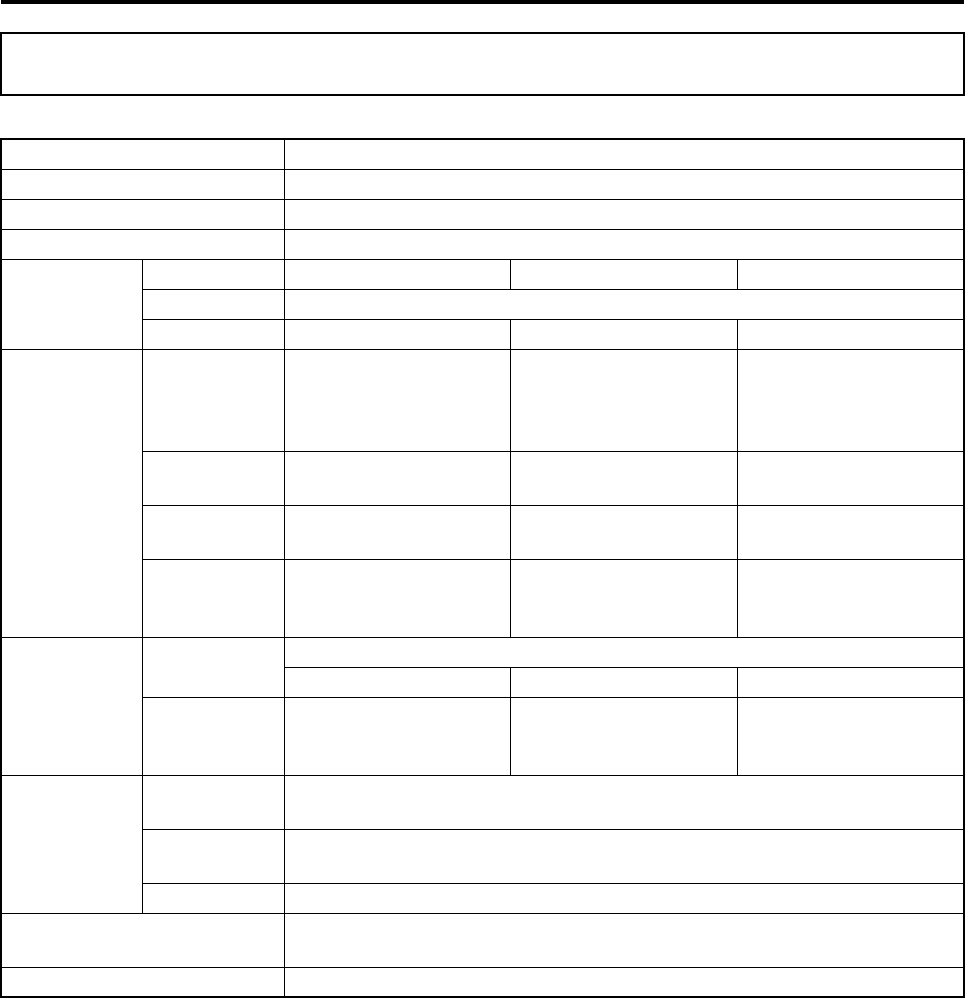
7-1
Specifications
Specifications Data
Item Data
Device Name Liquid sprayer
Spraying Method Category Low-volume liquid spraying
Spray Volume 8L/ha
Spray
Specifications
Flight Velocity 13 to 20 km/h 15 km/h 10 to 20 km/h
Flight Altitude 3 to 4 m
Flight Width 7.5 m 3.75 m 7.5 m
Discharge
Performance
Speed-
Dependent
Discharge
Method
Ye s N o N o
Discharge
Method
Nozzle method
(left/right)
Nozzle method
(center)
Nozzle method
(left/right)
Discharge
Pressure
0.17 to 0.44 Mpa
(at 13 to 20 km/h)
0.25 Mpa
(at 15 km/h)
0.44 Mpa
(at 20 km/h)
Maximum
Discharge
Volume
2.0 L/min 0.75 L/min 2.0 L/min
Nozzle
Nozzle
Method
Flat type
XR11002 XR8002 XR11002
Standard
Number of
Nozzles
212
Pump
Pumping
Method Double-acting piston method
Driving
Method Motor-driven
Power Rating DC12V (supplied by helicopter)
Maximum Chemical Tank
Load Capacity 16 L (8 L per tank)
Device Weight 7.4 kg
R-max.book Page 1 Tuesday, January 17, 2012 3:08 PM
8-1
Product Inspection
The prescribed types of inspections are described below.
•The pre-flight inspection is to be performed by the operator.
•For periodic inspections and replacement of parts, contact your dealer or an authorized service facility for
Yamaha unmanned helicopters for industrial applications.
Pre-Flight Inspection
Before a flight, make sure to inspect the following:
Periodic Inspection
* The inspection items and descriptions may change for various reasons.
About Inspections
Failure to perform pre-flight and regular
inspection could lead to problems. There-
fore, make sure to perform these inspections.
NOTICE
Part Names Description
Battery (9.6V for transmitter) Check fully charged
Filter Check for debris and tear
Chemical Tank Check for leaking valve
Joint Check for leaking valve
Cock Release air pockets
Complete Nozzles Check discharge condition
Section Description
Joints Disassemble, inspect, adjust, clean, replace
Chemical Tank Inspect and replace
Nozzle Clean
Pump Clean and replace
Hoses Inspect and replace
Filter Clean and replace
Other Inspect, correct, tighten
1
2
3
4
5
6
7
8
R-max.book Page 1 Tuesday, January 17, 2012 3:08 PM

Product Inspection
8-2
Replacement Parts
The following parts are consumables. If a deterioration in performance is seen due to wear, damage, deterio-
ration of a part, replace these parts.
The replacement parts may change due to various reasons.
* The frequency of replacement varies with chemicals used.
Part Names Description of Problems
Seat 1, Seat 2 (Nozzle parts) Leakage, dripping
O-ring (joint) Leakage
Seal valve (joint) Leakage
Valves Leakage
Pump unit assembly Leakage, poor discharge
R-max.book Page 2 Tuesday, January 17, 2012 3:08 PM

Customer Support
To pose any questions regarding the product you are using, to
make a comment regarding service, or to file a complaint, please
contact your dealer.
RMAX
OPERATION MANUAL
©2011 by Yamaha Motor Co., Ltd.
1st edition, Dec. 2011
All rights reserved.
Any reprinting or unauthorized use
without the written permission of
Yamaha Motor Co., Ltd.
is expressly prohibited.
Printed in Japan.
R-max.book Page 1 Tuesday, January 17, 2012 3:08 PM

PRINTED ON RECYCLED PAPER 11.12 – 0.3 × 1 CR
R-max.book Page 2 Tuesday, January 17, 2012 3:08 PM