Korea Data Systems Co CT1702 17” LCD TV Monitor User Manual 1 intro1 1904
Korea Data Systems Co Ltd 17” LCD TV Monitor 1 intro1 1904
Contents
- 1. Users manual1
- 2. Users manual 2
Users manual 2
CONFIGURING AND ADJUSTING THE DISPLAY
24
Configuring and Adjusting the Display : ANALOG(PC) Mode
Using the system’s OSD menus, you can adjust and refine your monitor’s image.
The following table describes the initial set-up steps and the other menus available.
Remember, when using the buttons on the front of your monitor:
Press the AUTO button to activate the auto adjustment function.
Press the MENU button to display the main menu.
Use the ◀ ▶ buttons to scroll through the menu items or to
increase/decrease the value/parameter.
Press the SELECT button to choose the desired menu item and to store
the new value/parameter.
★ Select the Input Source Mode
1. After all the connections are made, turn ON both the Computer
and the Monitor.
2. Select the Input Source mode by using either the Remote Control:
Pressing (repeatedly) the SOURCE button
Or
The buttons on the front of the Monitor by:
Pressing the SELECT button (repeatedly) to scroll through the various
Input Source modes
Or
From the Main Menu, choose the SELECT INPUT.
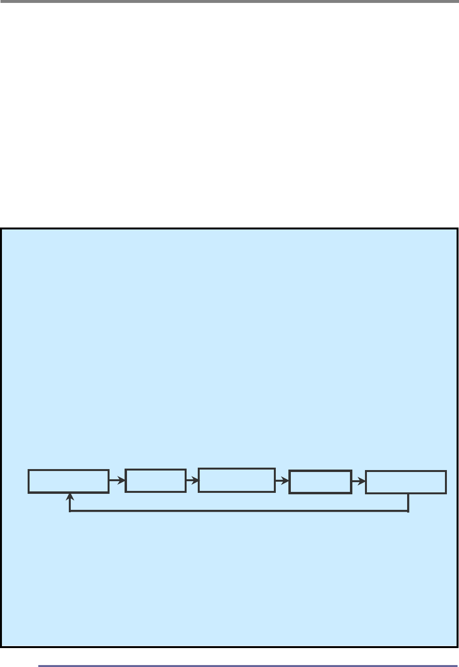
3. Select the ANALOG(PC) mode.
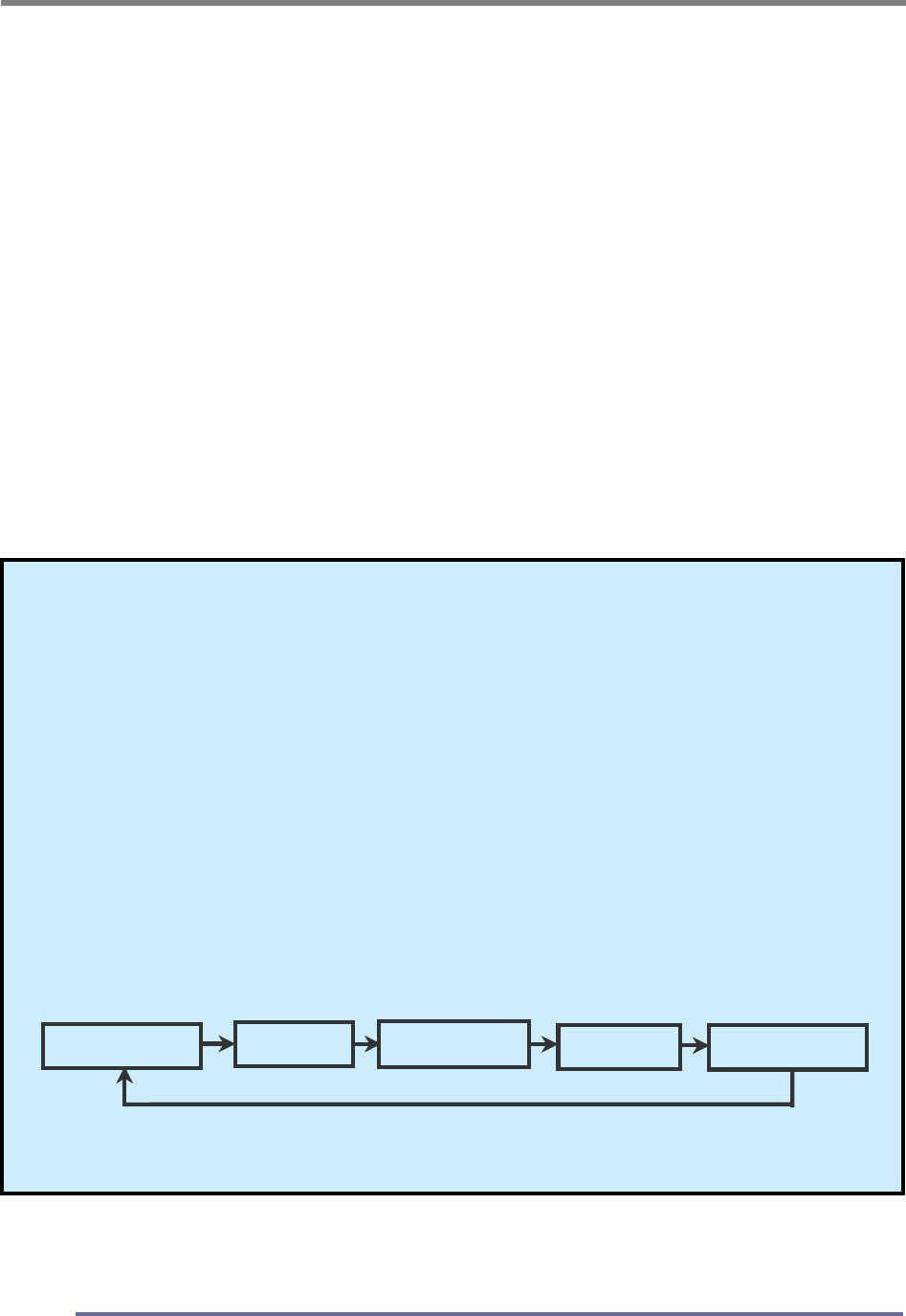
Analog(PC) Digital S-Video Tuner(TV)
Composite
CONFIGURING AND ADJUSTING THE DISPLAY
25
★ Monitor Driver Installation Procedure
1. Turn on the monitor and the computer.
2. Insert the KDS monitor Driver CD into the CD or DVD drive of
your computer.
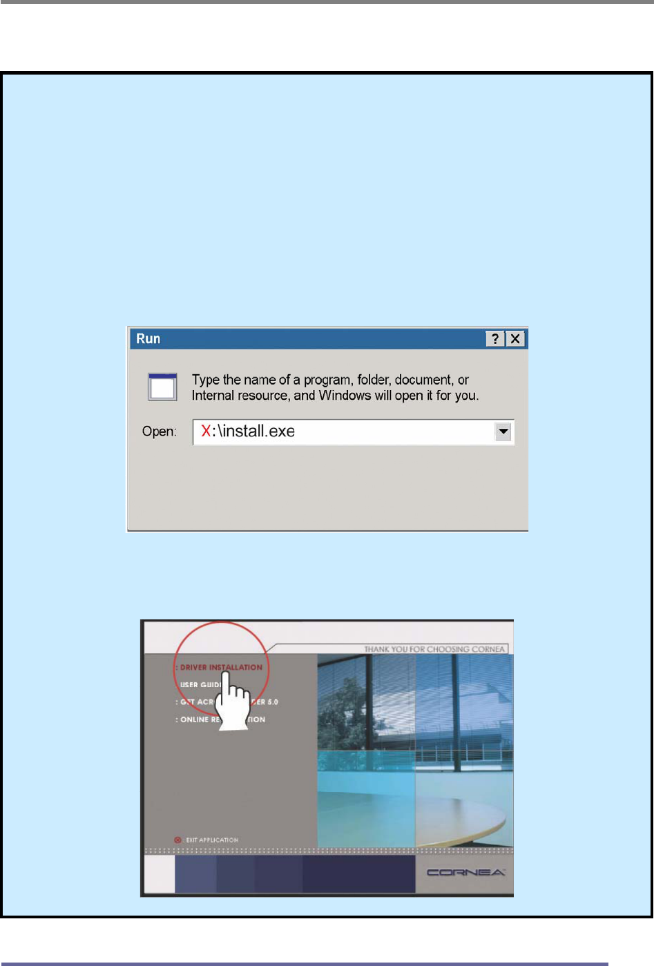
3. If the Main Menu screen dose not appear, click the Start button,
click RUN and go to Step 4. Otherwise, go to Step 5.
4. Type X:\ install.exe (replace the letter “X” with the letter
representing your CD or DVD drive), and click OK.
5. Click Install Driver and follow the instructions to complete the
installation.

CONFIGURING AND ADJUSTING THE DISPLAY
26
6. To Change the Resolution or Refresh Rate:
Right Click on your desktop to open the pop-up menu(for Windows
95/98/2000/XP).
With the left mouse button, click on Properties to open the Display
Properties menu.
Click on the Setting tab and change to resolution desired.
Click Apply or OK button, then click OK to keep the selected resolution.
Go back to the Display Properties menu and click on the Setting tab.
Select Advanced Properties and then click on Adapter.
In Adapter Properties, select Refresh Rate and change to the desired
rate.
Our monitors support a refresh rate up to 75Hz. For the best possible
image quality, we recommend a refresh rate of 60Hz.
If these options do not auto do not automatically pop up on your
screen, try the procedure again after installing the monitor driver.
CONFIGURING AND ADJUSTING THE DISPLAY
27
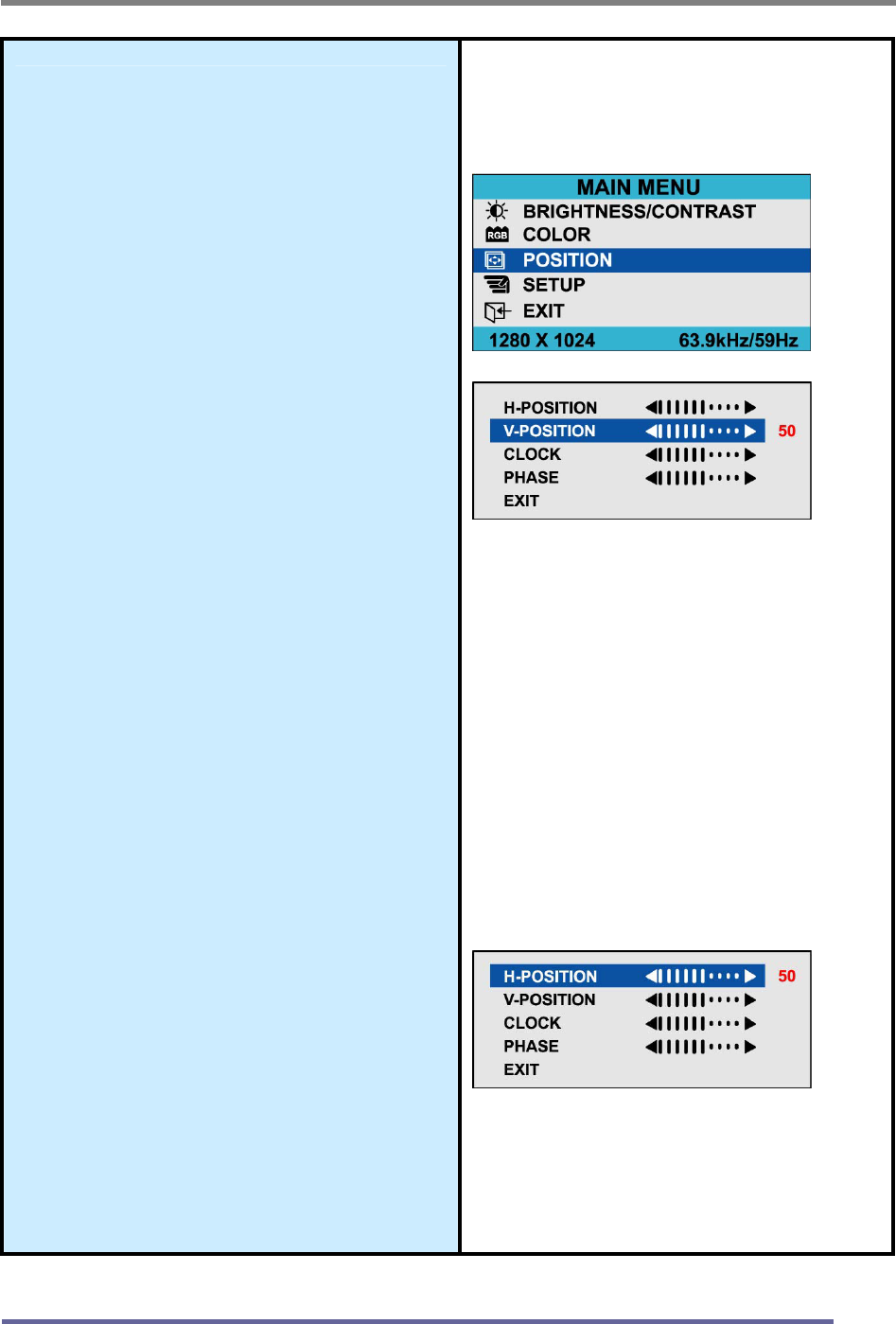
Adjust the Initial Image:
Vertical and Horizontal Alignment
7. If it is necessary to adjust the
vertical position of the initial
display:
Press the MENU button to
display the main menu.
Press the ◀▶buttons
repeatedly to scroll to the
Position icon.
Press the SELECT button to
select this menu item.
Press the ◀▶buttons
(repeatedly) to scroll to the
Vertical Position icon on the
sub-menu.
In the Vertical Position sub-
menu, use the ◀▶buttons to
move the image up or down until
it is centered vertically on the
screen.
Once you have vertically
centered the image, press the
SELECT button.
8. If it is necessary to adjust the
horizontal position of the initial
display:
Repeat the steps listed above
instead selecting Horizontal
Position from the sub-menu.
Remember to press the
SELECT button when the
display is centered horizontally.
Vertical Position:
Horizontal Position:
CONFIGURING AND ADJUSTING THE DISPLAY
28
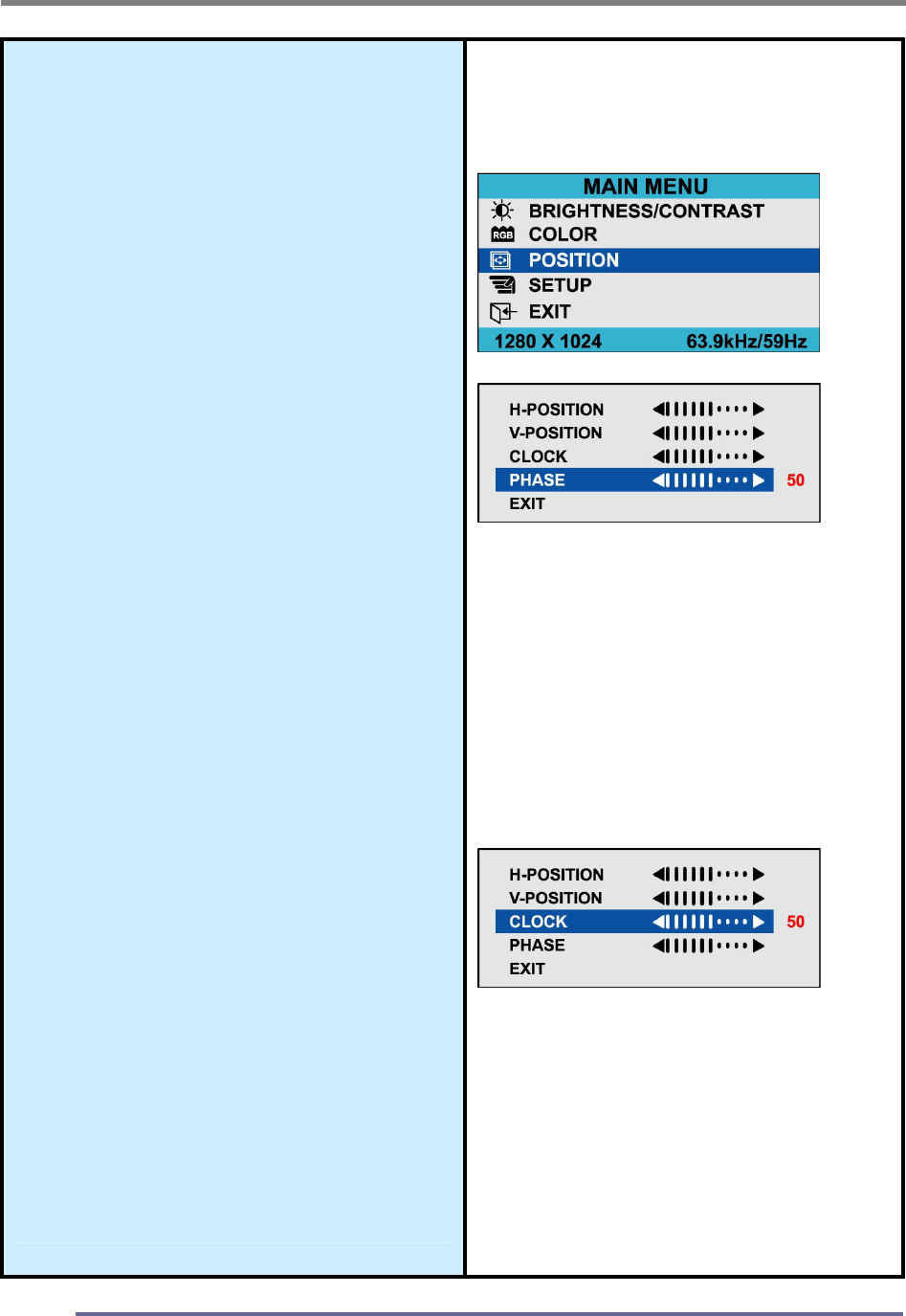
Adjust the Clarity of the lmage:
Phase
9. If it is necessary to adjust the
clarity of the image:
Press the MENU button to
display the main menu.
Press the ◀▶buttons
repeatedly to scroll to the
Image icon.
Press the SELECT button to
select this menu item.
Press the ◀▶buttons
repeatedly to scroll to the
Phase icon on thesub-menu.
In the Phase sub-menu, press
the ◀▶buttons to adjust the
clarity of the image.
Once you have the clarity set
to your liking, press the
SELECT button.
Clock
10. If it is necessary to tune a
rough image:
Repeat the steps listed above
instead chosing Clock on the
sub-menu.
Remember to press the
SELECT button when you
have the image set to your
liking.
Phase:
Clock:
CONFIGURING AND ADJUSTING THE DISPLAY
29
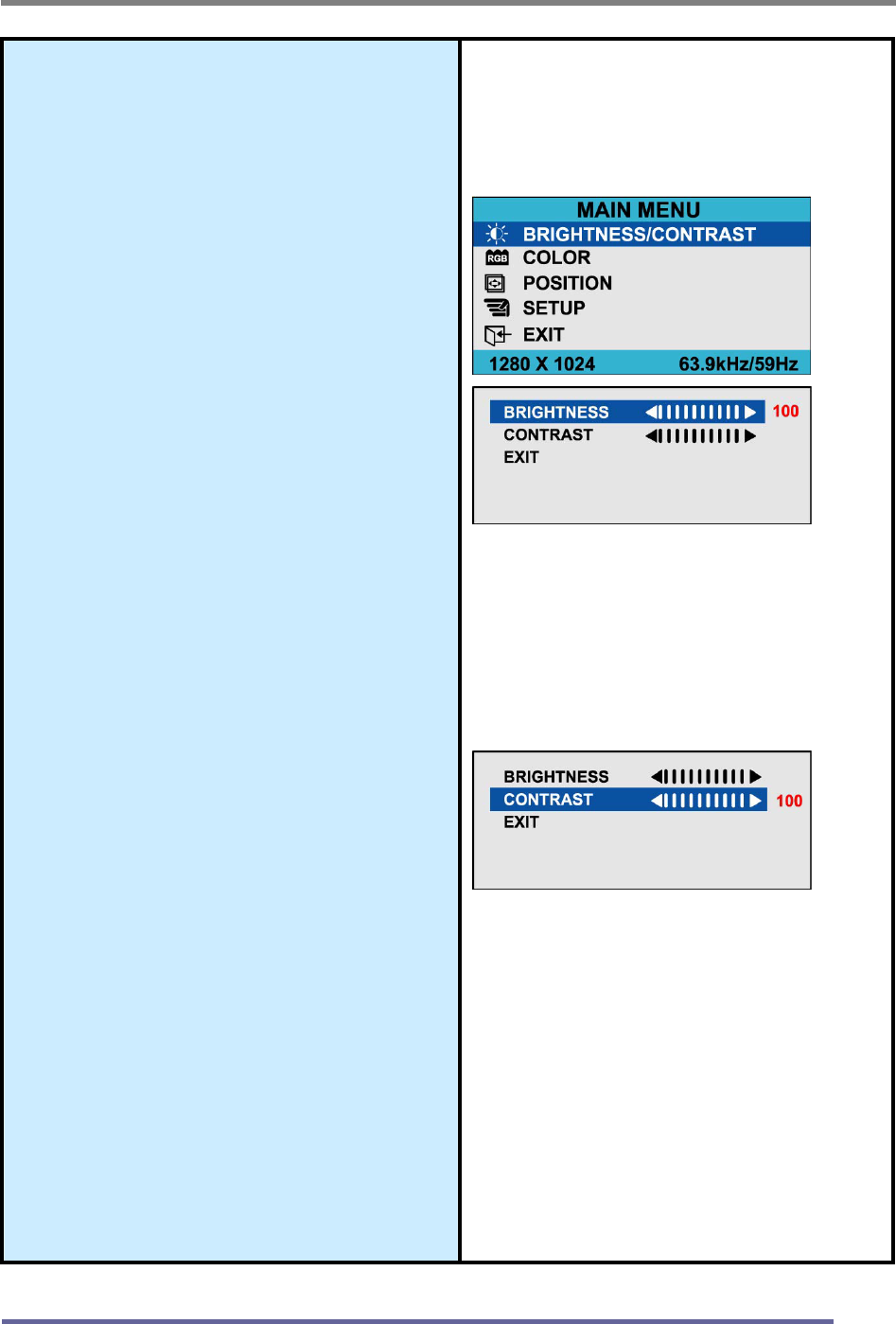
Adjust the Brightness and
Contrast:
11. To change the overall image
and brightness of the
background screen:
Press the MENU button to
display the main menu.
Press the ◀▶buttons
repeatedly to scroll to the
Brightness icon.
Press the SELECT button to
choose this menu item.
Press the ◀▶buttons to adjust
the brightness of the image.
Once you have the brightness
set to your liking, press the
SELECT button.
12. To change image brightness in
relation to the background:
Press the MENU button to
display the main menu.
Press the ◀▶buttons
repeatedly to scroll to the
Contrast icon.
Press the SELECT button to
choose this menu item.
Press the ◀▶buttons to adjust
the contrast of the image.
Once you have the contrast set
to your liking, press the
SELECT button.
Brightness
Contrast
CONFIGURING AND ADJUSTING THE DISPLAY
30
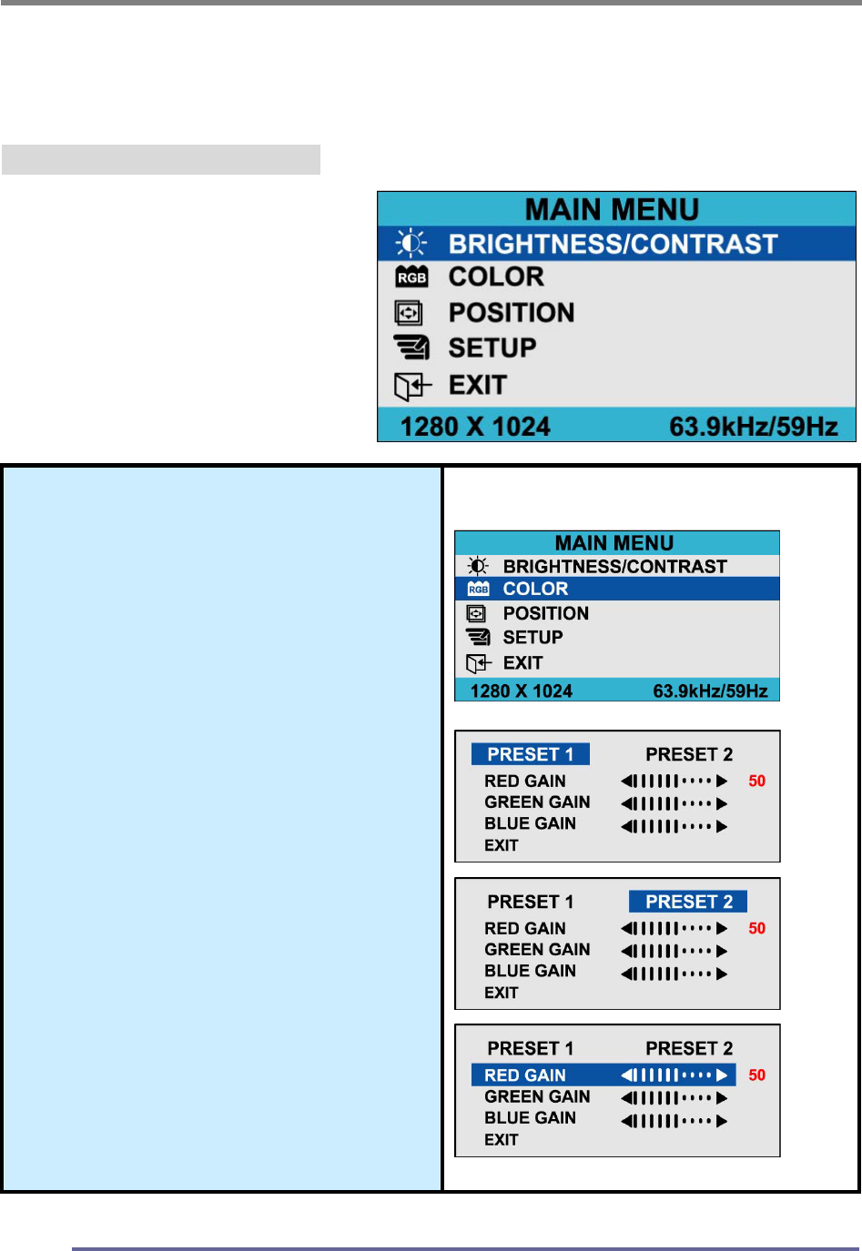
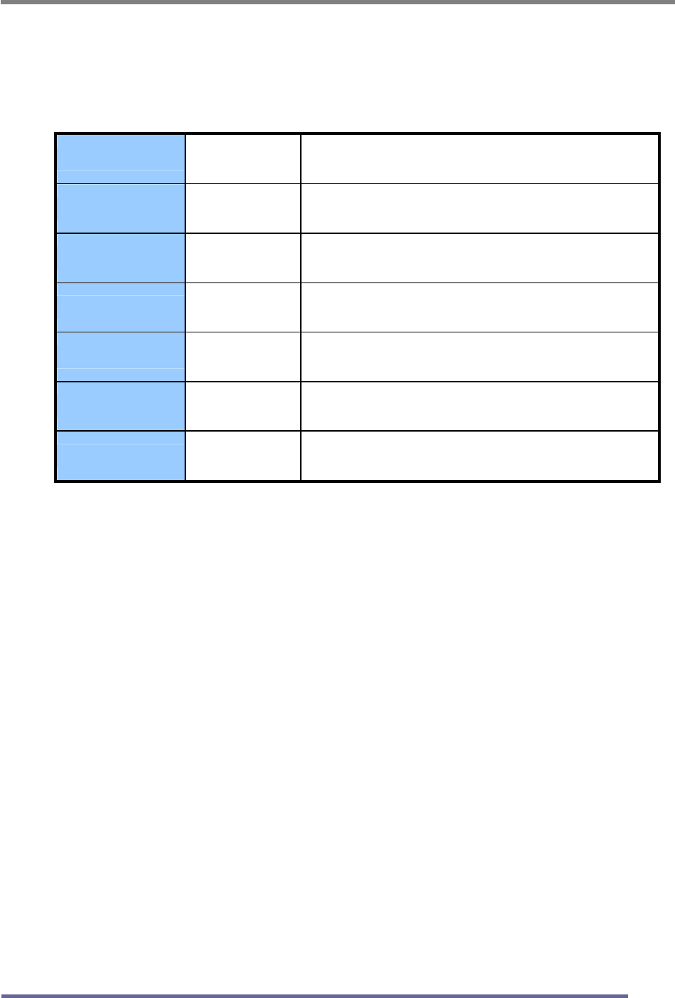
Explanation of Remaining Menu Items : ANALOG(PC) Mode
The following table describes the other menus available.
Figure 9: The Main Menus:
Color
Fine-tunes the viewing of color
images and background
settings.
Preset 1
Sets the background as bluish-
white.
Preset 2
Sets the background as plain
white.
User Color
Controls the individual levels of
red, green and blue.
CONFIGURING AND ADJUSTING THE DISPLAY
31
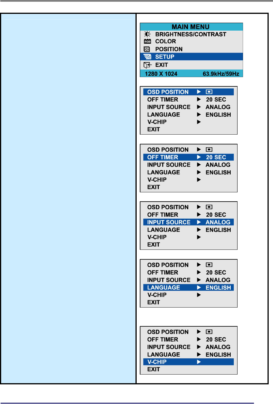
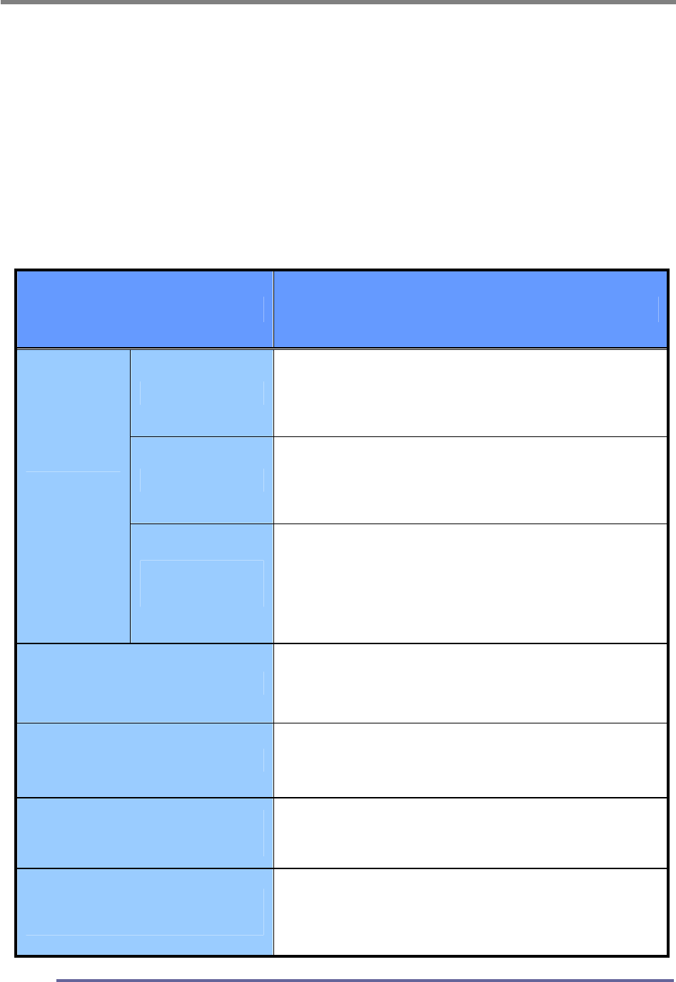
Setup
H Position
Controls the horizontal
position of the OSD.
V Position
Controls the vertical position
of the OSD.
Off Timer
Controls the OSD display
time during the absence of
user control.
Input Source
Change of input signal into
PC(ANALOG), DIGITAL,
COMPOSITE, S-VIDEO,
TUNER(TV)
Language
Controls the language used
by the OSD menu promts.
Available languages are
English, Deutsch, Français,
Español, Italiano.
V-Chip Setting
See page 40.
CONFIGURING AND ADJUSTING THE DISPLAY
32
Configuring and Adjusting the Display : Video(S-Video) Mode
Using the system’s OSD menus, you can adjust and refine your monitor’s image.
The following table describes the initial set-up steps and the other menus available.
Remember, when using the buttons on the front of your monitor:
Press the AUTO button to activate the auto adjustment function.
Press the MENU button to display the main menu.
Use the ◀ ▶ buttons to scroll through the menu items or to
increase/decrease the value/parameter.
Press the SELECT button to choose the desired menu item and to store
the new value/parameter.
★ Select the Input Source Mode
1. After all the connections are made, turn ON both the Computer
and the Monitor.
2. Select the Input Source mode by using either the Remote Control:
Pressing (repeatedly) the SOURCE button
Or The buttons on the front of the Monitor by:
Pressing the SELECT button (repeatedly) to scroll through the various
Input Source modes
Or
From the Main Menu, choose the SELECT INPUT.
3. Select the S-VIDEO mode.
★ Adjust the Image Position & Clarity
4. If necessary,
To adjust the BRIGHTNESS of the image, see page 29.
To adjust the CONTRAST of the image, see page 29.
Analog(PC) Digital S-Video Tuner(TV)
Composite
CONFIGURING AND ADJUSTING THE DISPLAY
33
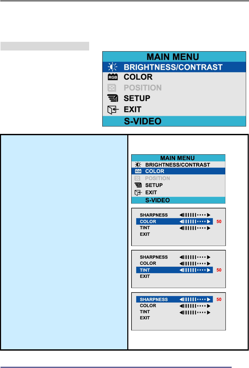
Explanation of Remaining Menu Items : Video(S-Video) Mode
The following table describes the other menus available.
Figure 9: The Main Menus:
Color
Fine-tunes the viewing of color
images and background
settings.
Color
Control of color thickness
signal level.
Tint
Control of color tone signal
level.
Sharpness
Control of sharpness signal
level.
CONFIGURING AND ADJUSTING THE DISPLAY
34
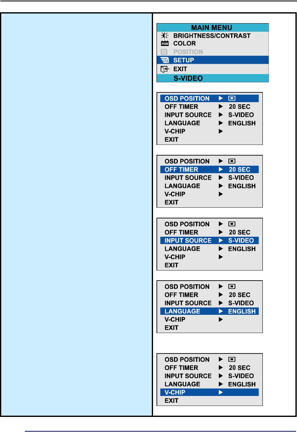
Setup
H Position
Controls the horizontal position
of the OSD.
V Position
Controls the vertical position of
the OSD.
Off Timer
Controls the OSD display time
during the absence of user
control.
Select Input
Change of input signal into
PC(ANALOG), DIGITAL,
COMPOSITE, S-VIDEO,
TUNER(TV)
Language
Controls the language used by
the OSD menu promts.
Available languages are
English, Deutsch, Français,
Español, Italiano.
V-Chip Setting
See page 40.
CONFIGURING AND ADJUSTING THE DISPLAY
35
Configuring and Adjusting the Display : TUNER(TV) Mode
Using the system’s OSD menus, you can adjust and refine your monitor’s image.
The following table describes the initial set-up steps and the other menus available.
Remember, when using the buttons on the front of your monitor:
Press the AUTO button to activate the auto adjustment function.
Press the MENU button to display the main menu.
Use the ◀ ▶ buttons to scroll through the menu items or to
increase/decrease the value/parameter.
Press the SELECT button to choose the desired menu item and to store
the new value/parameter.
★ Select the Input Source Mode
1. After all the connections are made, turn ON both the Computer
and the Monitor.
2. Select the Input Source mode by using either the Remote Control:
Pressing (repeatedly) the SOURCE button
Or The buttons on the front of the Monitor by:
Pressing the SELECT button (repeatedly) to scroll through the various
Input Source modes
Or
From the Main Menu, choose the SELECT INPUT.
3. Select the TUNER(TV) mode.
★ Adjust the Image Position & Clarity
4. If necessary,
To adjust the BRIGHTNESS of the image, see page 29.
To adjust the CONTRAST of the image, see page 29.
Analog(PC) Digital S-Video Tuner(TV)
Composite
CONFIGURING AND ADJUSTING THE DISPLAY
36
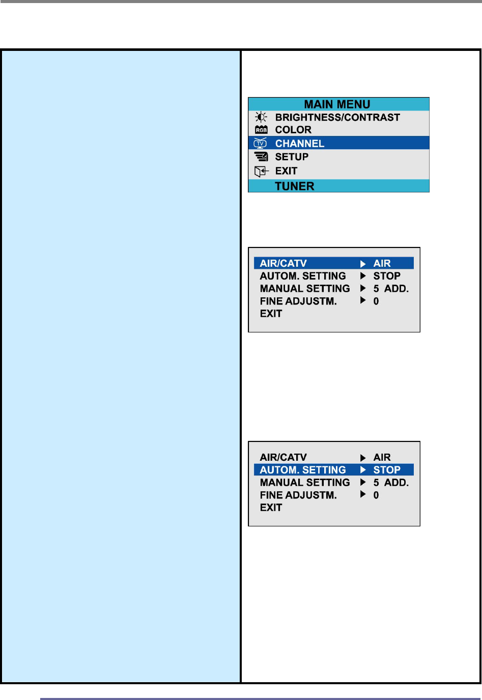
★ Select the Proper Antenna:
AIR/CATV
5. At the initial display, select the antenna
appropriate for your system by:
Pressing the MENU button to
display the Main Menu.
Pressing the CHANNEL
▲▼buttons (repeatedly) to scroll
to the CHANNEL option.
Press the SELECT button to
select the item.
6. At the CHANNEL sub-menu:
If the AIR/CATV item is not
highlighted, use CHANNEL
▲▼buttons to scroll to it.
Press the SELECT button to fully
highlight the AIR/CATV item.
At the CHANNEL sub-menu,
use the VOLUME ◀▶buttons
to scroll through the antenna
options (Air or CATV).
Press the SELECT button to
choose the appropriate option.
Automatically Search for Channels
7. While in this sub-menu, to
automatically search/add channels
from the cable system:
Use the CHANNEL ▲▼ buttons, to
scroll to the AUTO CHANNEL item.
Press the SELECT button to fully
highlight and view the options for
this item.
The system will start automatically
searching and adding channels.
8. If you do not want to automatically
search /add channels: do not
select this option.
CONFIGURING AND ADJUSTING THE DISPLAY
37
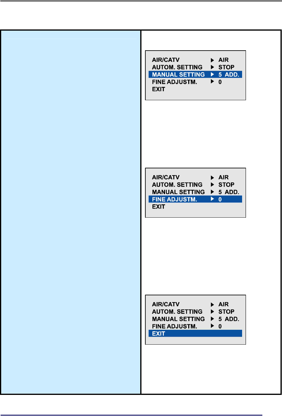
★ Other Sub-Menu Options:
Manually Add/Remove Channels:
9. While in this sub-menu:
Use the CHANNEL
▲▼buttons, to scroll to the
MANUAL CHANNEL item.
Press the SELECT button to
fully highlight and view the
options for this item.
Use the CHANNEL
▲▼❂uttons, to choose the ADD
or DELETE option as desired.
Refining the Video Image:
10. While in this sub-menu:
Use the CHANNEL
▲▼buttons, to scroll to the
FINE item.
Press the SELECT button to
fully highlight and view the
options for this item.•Use the
CHANNEL ▲▼❂uttons, to
increment the adjustment to
make the image as clear as
possible.
EXIT the Sub-Menu
11. Using the CHANNEL
▲▼buttons, to scroll to the EXIT
item.
12. Press the SELECT button.
This action returns you to the
Main Menu.
CONFIGURING AND ADJUSTING THE DISPLAY
38
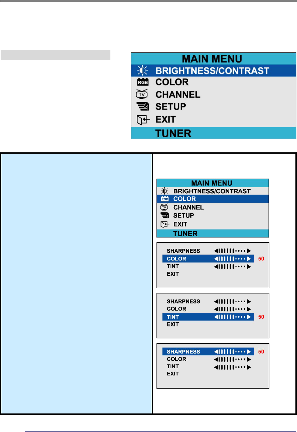
Explanation of Remaining Menu Items : TUNER(TV) Mode
The following table describes the other menus available.
Figure 9: The Main Menus:
Color
Fine-tunes the viewing of color
images and background
settings.
Color
Control of color thickness
signal level.
Tint
Control of color tone signal
level.
Sharpness
Control of sharpness signal
level.
CONFIGURING AND ADJUSTING THE DISPLAY
39
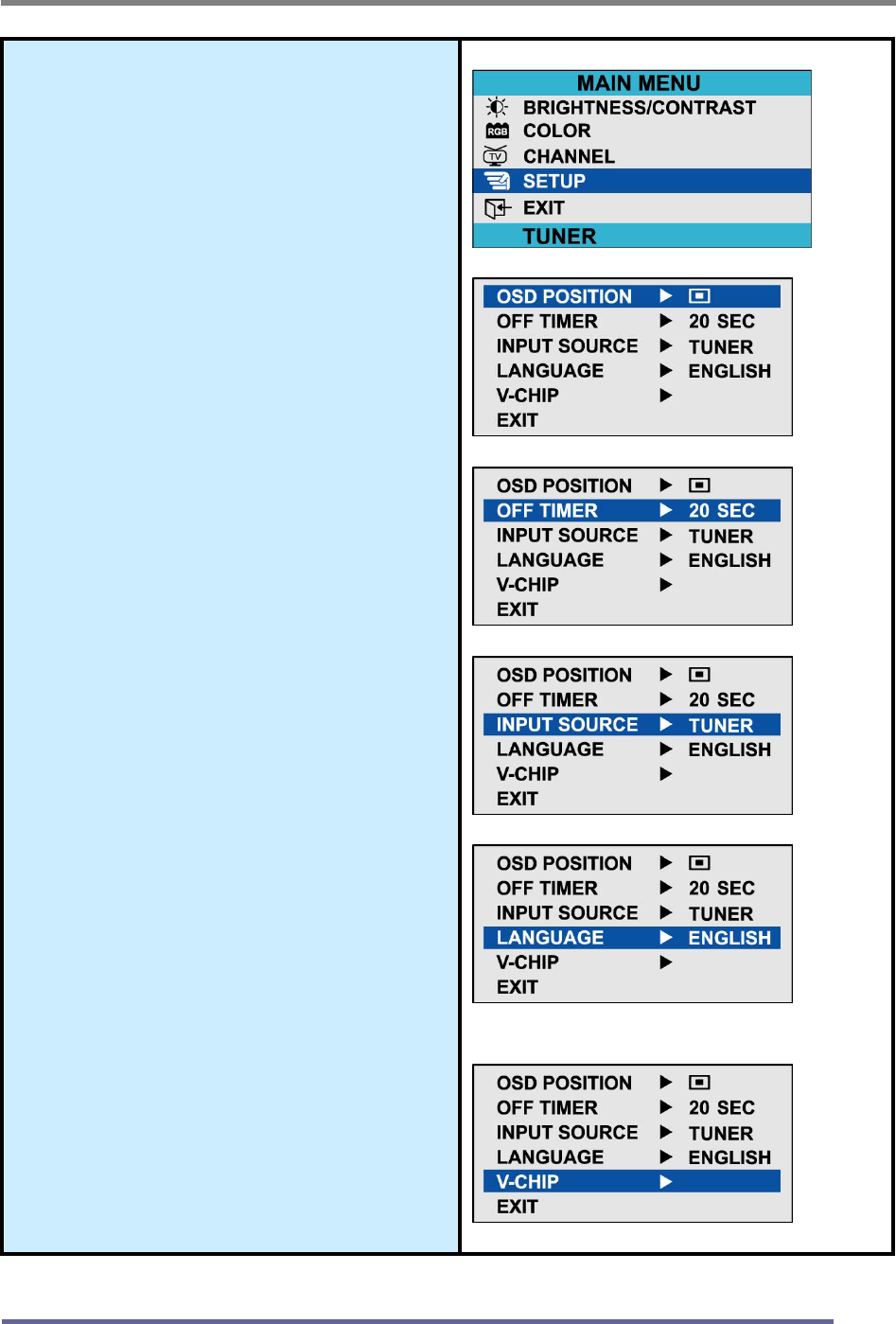
Setup
H Position
Controls the horizontal position
of the OSD.
V Position
Controls the vertical position of
the OSD.
Off Timer
Controls the OSD display time
during the absence of user
control.
Input Source
Change of input signal into
PC(ANALOG), DIGITAL,
COMPOSITE, S-VIDEO,
TUNER(TV)
Language
Controls the language used by
the OSD menu promts.
Available languages are
English, Deutsch, Français,
Español, Italiano.
V-Chip Setting
See page 40.
CONFIGURING AND ADJUSTING THE DISPLAY
40
★ V- Chip Setting
The Telecommunications Act of 1996 in USA requires that every television made, starting
in 1998, must be equipped with the technological device named V - Chip. The V - Chip can
block certain rated television shows off television (if chosen) so children cannot watch
programs that their parents do not approve. With this device, program-rating information
will be transmitted along with the television signal, and be decoded by the chip in each
television. The chip will then compare the rating codes to values preset by the viewer,
which is meant to be the parents. If the rating codes are higher than the preset values, the
television signal will be blocked, and a blank screen will be displayed.
KDS CT1503/1702 have this feature and you can adjust the V - Chip setting via OSD.
Use arrow keys on the remote controller or control buttons on the front cabinet of the
monitor to change the setting.
1. Select V - Chip on OSD, then enter 4 digits of pin number.
A. Initial pin number is “0000”
B. If you enter an incorrect pin number “Incorrect” message will be displayed for 3
seconds.
2. Use arrow keys to change or to activate the highlighted function.
3. Setting up TV Guidelines
C. Use Up/Down/Left/Right arrow buttons to move around the matrix and press
Menu button to change the value from "U" to "B" or "B" to "U"
D. U : Unblock B : Block
AII FV V S L D
TV-Y B
TV-Y7 B B
TV-G U
TV-PG U U U U U
TV-14 U U U U
TV-MA U U U U
TV-Y : Young Children
TV-Y7 : Children 7 and over
TV-G : General Audience
TV-PG : Parent Guidance
TV-14 : Viewers 14 and over
TV-MA : Mature audience
FV : Fantasy Violence
V : Violence
S : Sexual Situation
L : Coarse Language
D : Suggestive Dialog
CONFIGURING AND ADJUSTING THE DISPLAY
41
4. Setting up MPAA rating Mode
E. Use Up/Down/Left/Right arrow buttons to move around the matrix and press
Menu button to change the value from "U" to "B" or "B" to "U"
F. MPAA : Motion Picture Association (of) America [movie rating organization]
G U General Guidance
PG U Parental Guidance Suggested
PG-13 U Parental Strongly Cautioned
R U Restricted Under 17 Requires
NC-17 U No Children Under 17 Admitted
X U Adult Only
NR U Not Rated
5. Entering a new pin number
A. Use numeric keys enter a new pin number. Pin number confirm menu appears.
B. Again, use numeric keys to enter the pin number you entered at the previous
step. If the two pin numbers do not match, "INCORRECT PIN" message will be
displayed for 3 seconds.
6. Blocking Screen
A. If the incoming signal’s rating is higher than the one specified, the screen will be
blanked and "EXCESSIVE RATING" message will be appeared.
NOTE : When the screen is blocked by V-Chip, and if you want to change V-Chip setting,
press Exit button on the remote control or on the front cabinet of the monitor to
bring up OSD Menu
TROUBLESHOOTING
42
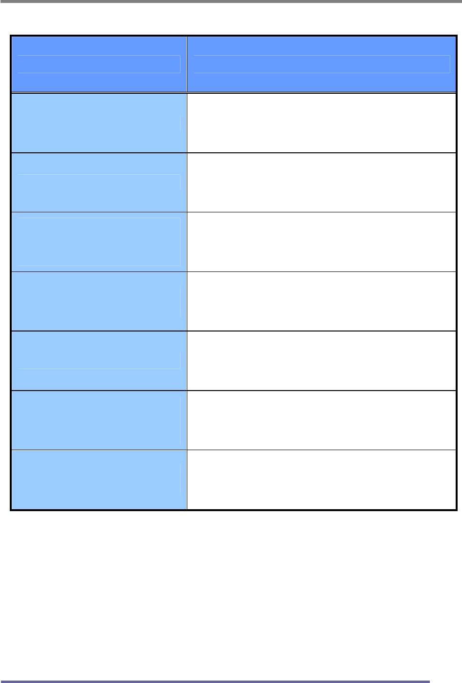
How to Resolve Potential Problems
This section tries to anticipate potential problems that you may encounter in the
day-to-day use of your monitor and aims to provide simple solutions to solve the
problem before it becomes more severe.
If, after trying the suggested solutions, your monitor’s continues to experience the
same problems, contact your authorized service center or call technical support.
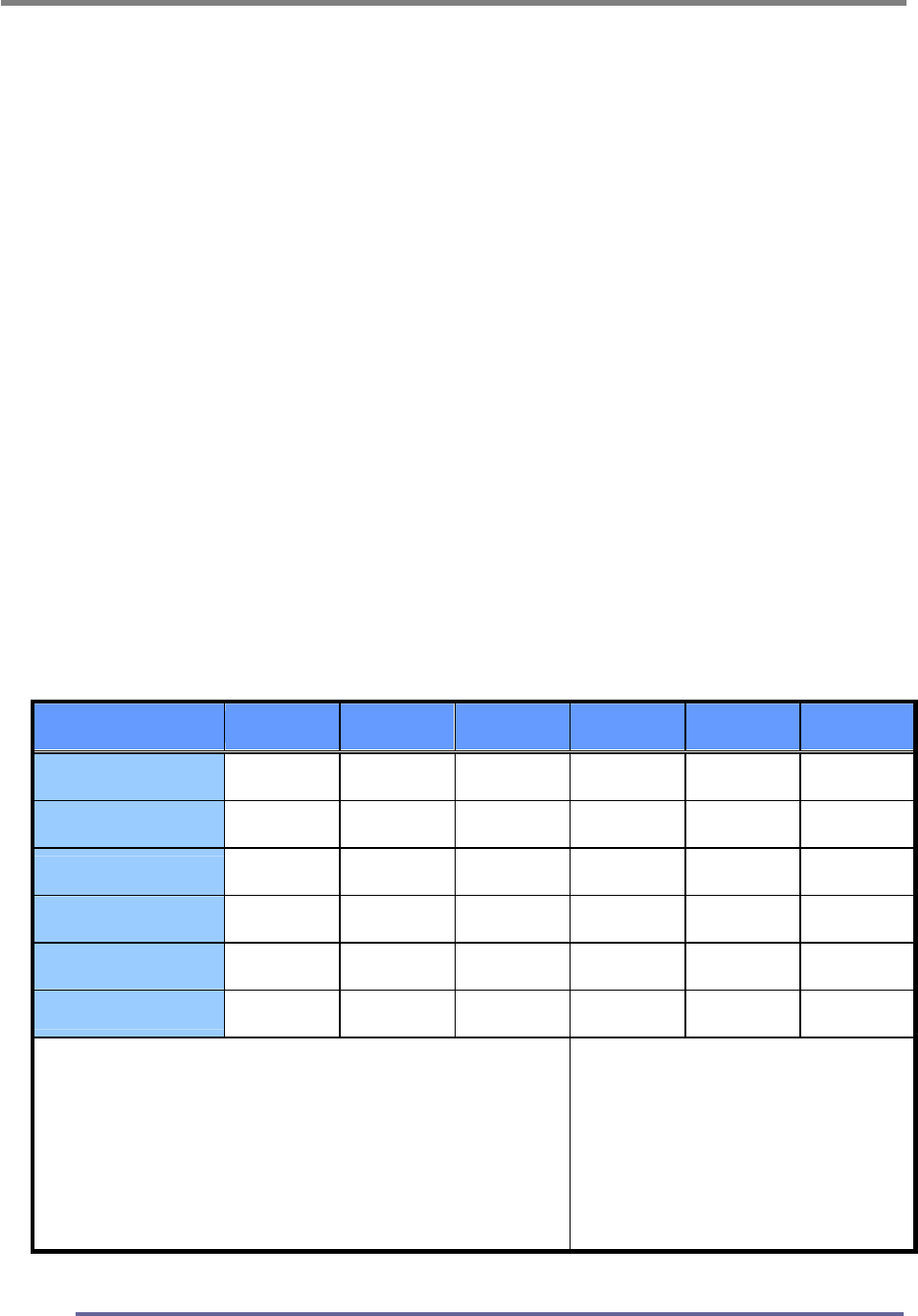
Troubleshooting scenarios
Problems Corrective Actions
LED ON
Using the OSD menu adjust the brightness
and contrast ratios to the maximums or
reset to their default settings.
LED OFF
Check the power switch and make sure the
AC power cord is properly connected to the AC
adapter.
NO
PICTURE
LED AMBER
OR BLINKING
Make sure the video signal cable is
properly connected at the back of monitor
and check to make sure the power to your
computer system is on.
DISPLAY IS NOT CLEAR Adjust the frequency and phase settings
using the OSD menu.
DISPLAY IS DARK Adjust the brightness and contrast settings
using the OSD menu.
IMAGE IS NOT
CENTERED
Adjust the horizontal and vertical position
settings using the OSD menu.
“OUT OF RANGE”
MESSAGE POPS UP
Check to make sure the resolution and the
frequency of the monitor are set within the
range require by your computer’s video port.
TROUBLESHOOTING
43
Problems Corrective Actions
PICTURE IS SCRAMBLED Check the signal cable connection between
your computer and monitor.
PICTURE IS FUZZY Perform auto-adjustment function.
PICTURE BOUNCES OR
HAS WAVY
OSCILLATIONS
Check the signal cable connection between
your computer and monitor.
PICTURE APPEARS TO
BE “GHOSTING”
Check the signal cable connection between
your computer and monitor.
COLOR IS NOT UNIFORM Adjust the color settings using the OSD
color menu.
COLORS ARE
DISTORTED WITH DARK
OR SHADOWED AREAS
Adjust the color settings using the OSD
color menu.
POWER INDICATOR IS
BLINKING AMBER
The monitor is using its power
management system. Check the power
management utility on your computer.
APPENDIX
44
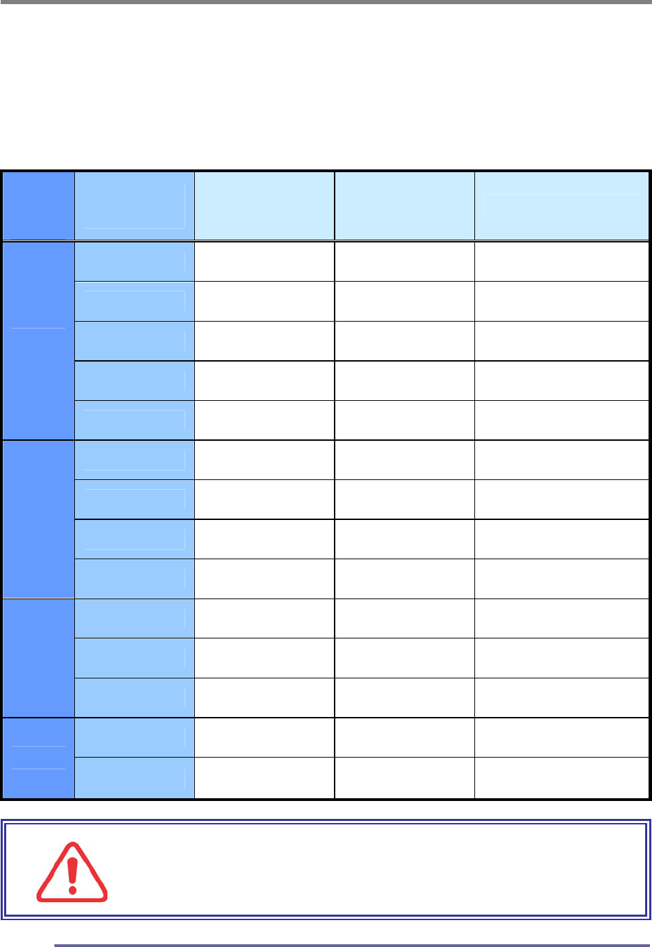
CT1702 Display Modes (Analog)
For the display modes listed below, the screen image has been optimized during
production.
Preset Timing Modes (Analog)
Mode
Display
Mode
Horizontal
Frequency
(KHz)
Vertical
Frequency
(Hz)
Standard Type
640 x 350 31.5KHz 70Hz IBM
720 x 400 31.5KHz 70Hz IBM
640 x 480 31.5KHz 60Hz Industry Standard
640 x 480 37.9KHz 72Hz VESA Standard
VGA
640 x 480 37.5KHz 75Hz VESA Standard
800 x 600 35.2KHz 56Hz VESA Guidelines
800 x 600 37.9KHz 60Hz VESA Guidelines
800 x 600 48.0KHz 72Hz VESA Standard
SVGA
800 x 600 46.9KHz 75Hz VESA Standard
1024 x 768 48.4KHz 60Hz VESA Guidelines
1024 x 768 56.5KHz 70Hz VESA Standard
XGA
1024 x 768 60.0KHz 75Hz VESA Standard
1280 x 1024 64.0KHz 60Hz VESA Standard
SXGA
1280 x 1024 80.0KHz 75Hz VESA Standard
IMPORTANT:
This Monitor is not supported outside of the display
modes listed above.
APPENDIX
45
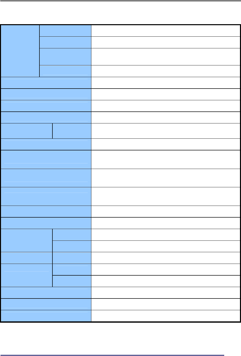
CT1702 Specifications (Type:G0H)
Type 17" (43.18Cm) Viewable Diagonal TFT Type
Pixel Pitch 0.264 mm (H) x 0.264 mm (V)
Viewable Angle
(CR ≥ 5)
Horizontal : ± 80˚ (Left/Right), TN Wide Angle
Vertical : +50˚ / -70˚ (Up/Down)
LCD
Viewable
Size
Glass Surface Anti-Glare, Hard-Coating (3H)
Contrast Ratio 500:1 (Typical)
Response Time 20ms (6ms [Rising] + 14ms [Falling])
Display Mode Normally White
Brightness 270 cd/ m2 (Max)
INPUT VGA RGB Analog, H/V Separate (TTL), Digital Input : DVI-D
Fh : 31 to 82 KHz Fv : 56 to 75 Hz
Input Resolution From VGA up to 1280 x 1024 at 60Hz
I/O Connectors VGA 15-pin D-sub, DC Power-in
Stereo Audio-In/Out
Power AC 110~240V, 50/60Hz Input (Built-in Adapter)
12V, 2.5A Max DC Output
User Controls
Brightness, Contrast, Color, Color Temperature, Auto-
Adjustment, Clock, Phase, H/V Position, 5 OSD Languages
Displayable color 16.7 M (Full Color)
Displayable Area 337.92mm (H) x 270.336mm (V)
Operation 0˚C ~ 40˚C (32˚F ~ 104˚F)
Temperature Storage -20˚C ~ 60˚C (-4˚F ~ 140˚F)
Dimensions Physical 424.0mm (W) x 404.0mm (H) x 165.0mm (D)
Net 4.4Kg (9.70lbs)
Weight Gross 6.6Kg (14.55lbs)
Regulations MIC, UL/cUL, CE, FCC-B, VCCI, CB, EPA Energy Star
Plug and Play VESA DDC 2B
Power Management VESA DPMS Compatible
“Note : Design and Specification are subject to change without notice.
Weight and Dimensions shown are approximate”
APPENDIX
46
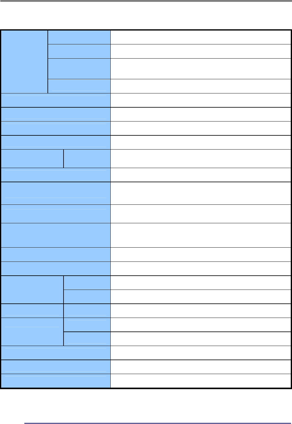
CT1702 Specifications (Type : G0S)
Type 17" (43.18Cm) Viewable Diagonal TFT Type
Pixel Pitch 0.264 mm (H) x 0.264 mm (V)
Viewable Angle
(CR ≥ 5)
Horizontal : ± 85˚ (Left/Right), TN Wide Angle
Vertical : +70˚ / -65˚ (Up/Down)
LCD
Viewable
Size
Glass Surface Anti-Glare, Hard-Coating (3H)
Contrast Ratio 350:1 (Typical)
Response Time 25ms (5ms [Rising] + 20ms [Falling])
Display Mode Normally White
Brightness 260 cd/ m2 (Max)
INPUT VGA RGB Analog, H/V Separate (TTL), Digital Input : DVI-D
Fh : 31 to 82 KHz Fv : 56 to 75 Hz
Input Resolution From VGA up to 1280 x 1024 at 60Hz
I/O Connectors VGA 15-pin D-sub, DC Power-in
Stereo Audio-In/Out
Power AC 110~240V, 50/60Hz Input (Built-in Adapter)
12V, 2.5A Max DC Output
User Controls
Brightness, Contrast, Color, Color Temperature, Auto-
Adjustment, Clock, Phase, H/V Position, 5 OSD Languages
Displayable color 16.2 M (Full Color)
Displayable Area 337.92mm (H) x 270.336mm (V)
Operation 0˚C ~ 40˚C (32˚F ~ 104˚F)
Temperature Storage -20˚C ~ 60˚C (-4˚F ~ 140˚F)
Dimensions Physical 424.0mm (W) x 404.0mm (H) x 165.0mm (D)
Net 4.1Kg (9.04lbs)
Weight Gross 6.3Kg (13.89lbs)
Regulations MIC, UL/cUL, CE, FCC-B, VCCI, CB, EPA Energy Star
Plug and Play VESA DDC 2B
Power Management VESA DPMS Compatible
“ Note : Design and Specification are subject to change without notice.
Weight and Dimensions shown are approximate”
APPENDIX
47
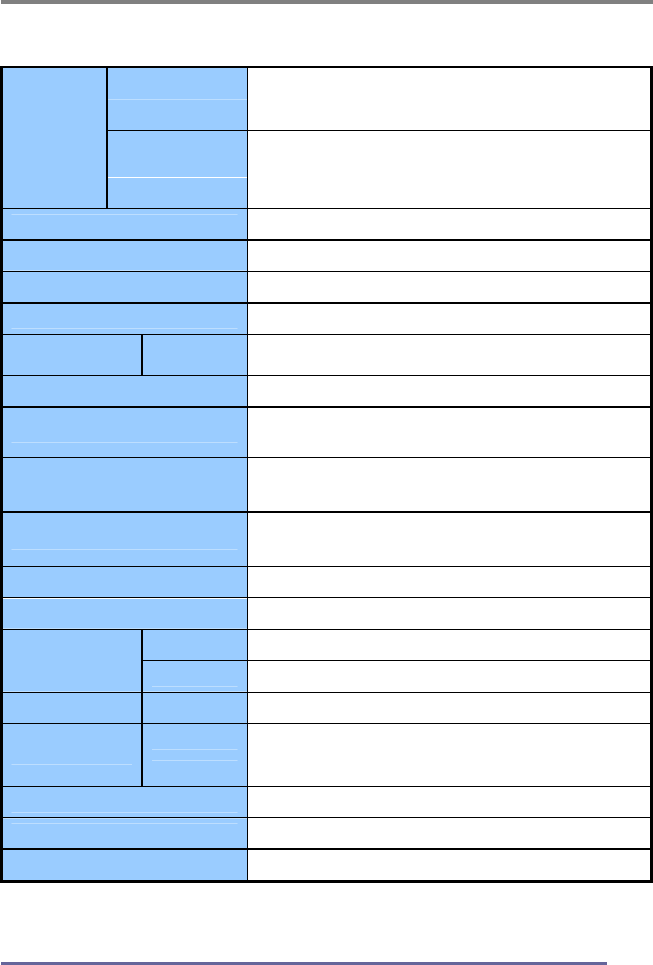
CT1702 Specifications (Type : G1H)
Type 17" (43.18Cm) Viewable Diagonal TFT Type
Pixel Pitch 0.264 mm (H) x 0.264 mm (V)
Viewable Angle
(CR ≥ 5)
Horizontal : ± 85˚ (Left/Right), TN Wide Angle
Vertical : ± 75˚ (Up/Down)
LCD
Viewable
Size
Glass Surface Anti-Glare, Hard-Coating (3H)
Contrast Ratio 430:1 (Typical)
Response Time 20ms (5ms [Rising] + 15ms [Falling])
Display Mode Normally White
Brightness 270 cd/ m2 (Max)
INPUT VGA RGB Analog, H/V Separate (TTL), Digital Input : DVI-D
Fh : 31 to 82 KHz Fv : 56 to 75 Hz
Input Resolution From VGA up to 1280 x 1024 at 60Hz
I/O Connectors VGA 15-pin D-sub, DC Power-in
Stereo Audio-In/Out
Power AC 110~240V, 50/60Hz Input (Built-in Adapter)
12V, 2.5A Max DC Output
User Controls
Brightness, Contrast, Color, Color Temperature, Auto-
Adjustment, Clock, Phase, H/V Position, 5 OSD Languages
Displayable color 16.2 M (Full Color)
Displayable Area 337.92mm (H) x 270.336mm (V)
Operation 0˚C ~ 40˚C (32˚F ~ 104˚F)
Temperature Storage -20˚C ~ 60˚C (-4˚F ~ 140˚F)
Dimensions Physical 424.0mm (W) x 404.0mm (H) x 165.0mm (D)
Net 4.4Kg (9.70lbs)
Weight Gross 6.6Kg (14.55lbs)
Regulations MIC, UL/cUL, CE, FCC-B, VCCI, CB, EPA Energy Star
Plug and Play VESA DDC 2B
Power Management VESA DPMS Compatible
“Note : Design and Specification are subject to change without notice.
Weight and Dimensions shown are approximate”

APPENDIX
48
Regulatory Compliance
Canadian Department of Communications Compliance Statement
DOC: This Class B digital apparatus meets all requirements of the Canadian
Interference-Causing Equipment Regulations.
C-UL: Bears the C-UL Mark and is in compliance with Canadian Safety
Regulations according to C.S.A. C22.2 No. 950.
U.S.A
U.S.FEDERAL COMMUNICATIONS COMMISSION RADIO FREQUENCY
INTERFERENCE STATEMENT INFORMATION TO THE USER
NOTE : This equipment has been tested and found to comply with the limits for a
Class B digital device, pursuant to part 15 of the FCC Rules.
These limits are designed to provide reasonable protection against harmful
interference in a residential installation.
This equipment generates, uses, and can radiate radio frequency energy, and, if
not installed and used in accordance with the instructions, may cause harmful
interference to radio communications.
However, there is no guarantee that interference will not occur in a particular installation.
If this equipment does cause harmful interference to radio or television reception, which
can be determined by turning the equipment off and on, the user is encouraged to try to
correct the interference by one or more of the following measures:
Reorient or relocate the receiving antenna.
Increase the separation between the equipment and receiver.
Connect the equipment into an outlet on a circuit different from that to which
the receiver is connected.
Consult your dealer or an experienced radio/TV technician for help.
Change or modification not expressly approved by the part responsible for
compliance could void the user’s authority to operate the equipment.
Connecting of peripherals requires the use of grounded shielded signal cables.

APPENDIX
49
Notice for Japan
This is a Class B product based on the standard of the Voluntary Control Council
for Interference from Information Technology Equipment (VCCI). If this is used
near a radio or television receiver in a domestic environment, it may cause radio
interference. Install and use the equipment according to the instruction manual.
CE Conformity
The device complies with the requirements of the EEC directive
89/336/EEC as amended by 92/31/EEC and 93/68/EEC Art.5
with regard to “Electromagnetic compatibility,” and 73/23/EEC as
amended by 93/68/EEC Art.13 with regard to “Safety.”