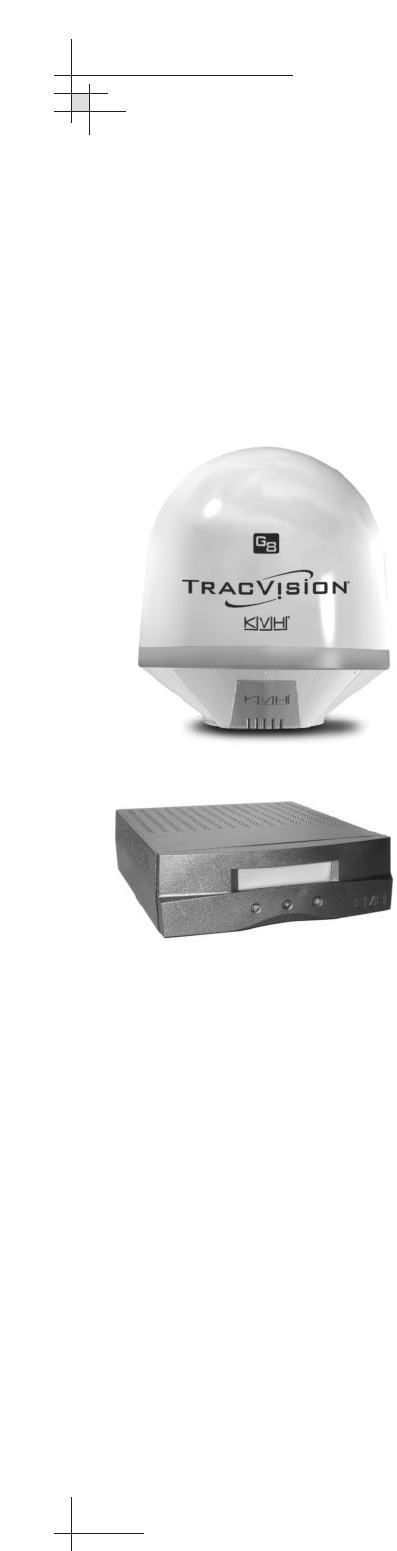
Kvh Industries Tracvision G8 Users Manual Owner's
TracVision G8 to the manual 88db0279-4057-4696-8b10-0027738b0974
2015-02-09
: Kvh-Industries Kvh-Industries-Tracvision-G8-Users-Manual-569258 kvh-industries-tracvision-g8-users-manual-569258 kvh-industries pdf
Open the PDF directly: View PDF ![]() .
.
Page Count: 137 [warning: Documents this large are best viewed by clicking the View PDF Link!]
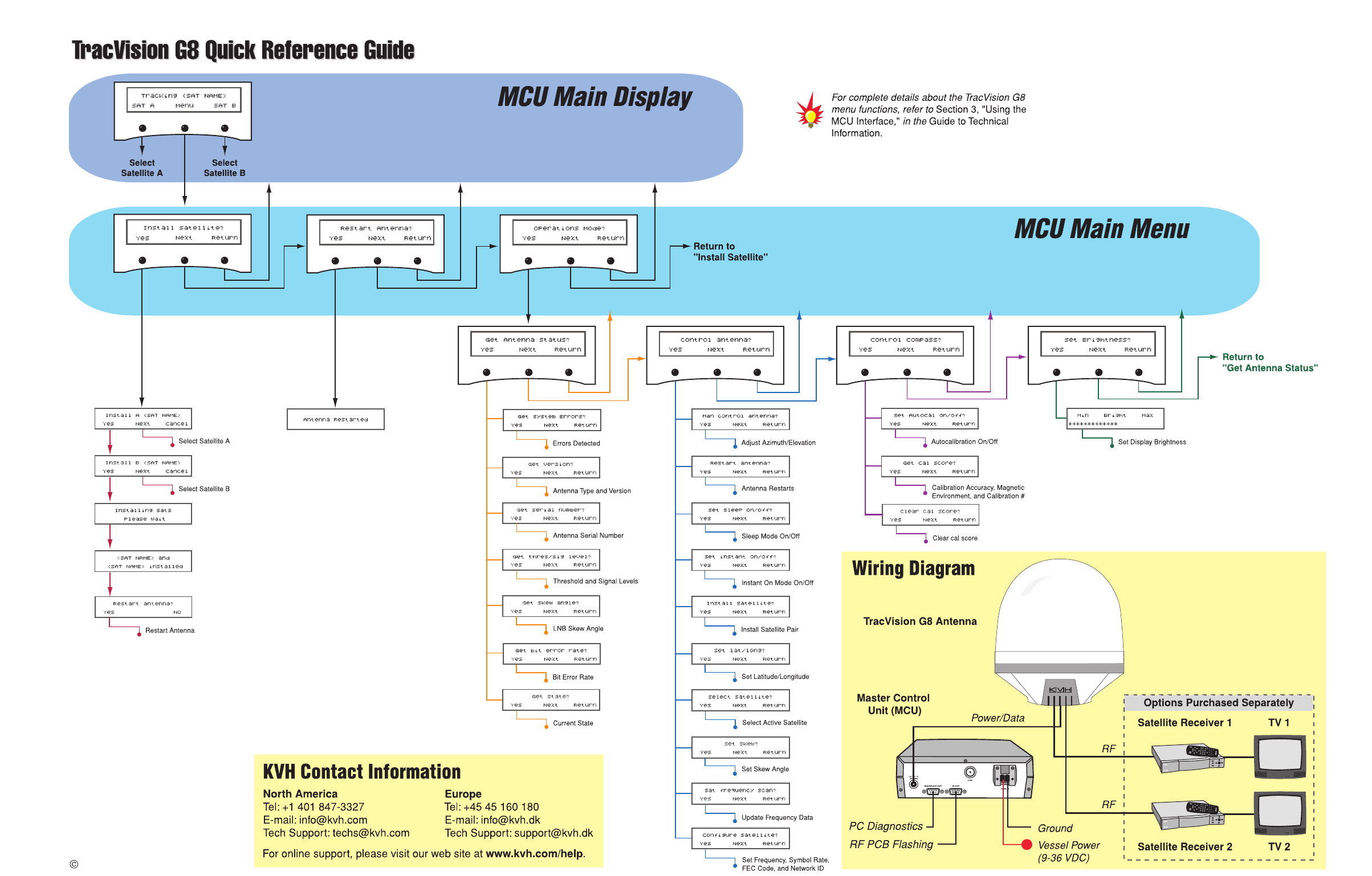
- Quick Reference Guide
- Welcome Page
- Table of Contents
- Guide to Operation
- Guide to Technical Information
- 1 - Introduction
- 2 - Installation
- 3 - Using the MCU Interface
- 4 - Troubleshooting
- 5 - Maintenance
- 5.1 - Warranty/Service Information
- 5.2 - Preventive Maintenance
- 5.3 - TracVision G8 Field Replaceable Units
- 5.4 - Accessing Antenna Components Through the Hatch
- 5.5 - Replacing the PCB Module Fuse
- 5.6 - Replacing the PCB Module
- 5.7 - Replacing the RF PCB
- 5.8 - Replacing the Internal Sensor
- 5.9 - Replacing the Azimuth Gyro
- 5.10 - Replacing the Elevation Gyro
- 5.11 - Replacing the Azimuth Motor
- 5.12 - Replacing the Azimuth Belt
- 5.13 - Replacing the Elevation Motor
- 5.14 - Replacing the Elevation Belt
- 5.15 - Replacing the Skew Motor
- 5.16 - Replacing the Skew Belt
- 5.17 - Replacing the LNB
- 5.18 - Replacing the LNB/Feed Tube Assembly
- 5.19 - Preparing for Shipment
- Appendices
- Index

owner’s
manual
•Guide to Operation
•Guide to Technical Information
A Guide to TracVision
®
G8
TVG8_OM_BinderCover_11.05
*
*
*
*
*
*
*
Notes
* Press any button to return.
** If GPS is providing valid position
data to the antenna, manual entry
of latitude/longitude is not available.
**
2005, KVH Industries, Inc.
TracVision G8
Owner’s Manual
This manual provides detailed instructions on the proper
operation, installation, configuration, troubleshooting, and
maintenance of the KVH TracVision G8 satellite TV system. For
operation instructions, refer to the Guide to Operation. For
installation, configuration, troubleshooting, and maintenance
instructions, refer to the Guide to Technical Information.
Throughout this manual, important information is marked for
your attention by these icons:
Direct questions, comments, or suggestions to:
KVH Industries, Inc. KVH Europe A/S
50 Enterprise Center Kokkedal Industripark 2B
Middletown, RI 02842-5279 USA 2980 Kokkedal, Denmark
Tel: +1 401 847-3327 Tel: +45 45 160 180
Fax: +1 401 849-0045 Fax: +45 45 160 181
E-mail: info@kvh.com E-mail: info@kvh.dk
Internet: www.kvh.com Internet: www.kvh.com
Please e-mail your comments about this manual to
manuals@kvh.com. Your feedback is greatly appreciated!
A helpful tip that either directs you to
a related area within the manual or
offers suggestions on getting the
best performance from your system.
An alert to important information
regarding procedures, product
specifications, or product use.
An electrical safety warning to help
identify electrical issues that can be a
hazard to either this KVH product or
a user.
Information about installation,
maintenance, troubleshooting, or
other mechanical issues.
KVH Part # 54-0198 Rev. D
© 2005 KVH Industries, Inc., All rights reserved.
TracVision G8 Serial Number
This serial number will be required
for all troubleshooting or service
calls made regarding this product.
Welcome to TracVision G8

TracVision®and KVH®are trademarks of KVH Industries, Inc.
DVB®(Digital Video Broadcasting) is a registered trademark of the DVB Project.
DIRECTV®is a registered trademark of DIRECTV, Inc.
DISH Network™is an official trademark of
EchoStar Communications Corporation.
ExpressVu is a property of Bell ExpressVu, a wholly owned
subsidiary of Bell Satellite Services.

54-0198
i
Table of Contents
Table of Contents
Guide to Operation . . . . . . . . . . . . . . . . . . . . . . . . . . . . . . . . . .1
1 System Overview . . . . . . . . . . . . . . . . . . . . . . . . . . . . . . . . . . . . . . . .3
2 Receiving Satellite Signals . . . . . . . . . . . . . . . . . . . . . . . . . . . . . . . .5
3 Turning On the System . . . . . . . . . . . . . . . . . . . . . . . . . . . . . . . . . . .6
4 Changing Channels and Switching to the Second Satellite . . . . .6
5 Watching Television . . . . . . . . . . . . . . . . . . . . . . . . . . . . . . . . . . . . . .8
6 Using the MCU Interface . . . . . . . . . . . . . . . . . . . . . . . . . . . . . . . . . .9
Guide to Technical Information . . . . . . . . . . . . . . . . . . . . . . . .11
1 Introduction . . . . . . . . . . . . . . . . . . . . . . . . . . . . . . . . . . . . . . . . . . .13
1.1 System Overview . . . . . . . . . . . . . . . . . . . . . . . . . . . . . . . . . .15
1.2 System Components . . . . . . . . . . . . . . . . . . . . . . . . . . . . . . .17
1.3 Materials Provided with the TracVision G8 . . . . . . . . . . . . . . .18
2 Installation . . . . . . . . . . . . . . . . . . . . . . . . . . . . . . . . . . . . . . . . . . . .19
2.1 Planning the Installation . . . . . . . . . . . . . . . . . . . . . . . . . . . . .21
2.2 Mounting the TracVision Antenna . . . . . . . . . . . . . . . . . . . . . .26
2.3 Connecting the Receiver(s) . . . . . . . . . . . . . . . . . . . . . . . . . .31
2.4 Wiring the MCU . . . . . . . . . . . . . . . . . . . . . . . . . . . . . . . . . . .35
2.5 Mounting the MCU . . . . . . . . . . . . . . . . . . . . . . . . . . . . . . . . .38
2.6 Activating/Programming the Receiver . . . . . . . . . . . . . . . . . . .40
2.7 Installing Satellites Using the MCU . . . . . . . . . . . . . . . . . . . .42
2.8 Checking Out the System . . . . . . . . . . . . . . . . . . . . . . . . . . . .52
2.9 Changing Geographic Location . . . . . . . . . . . . . . . . . . . . . . .54
3 Using the MCU Interface . . . . . . . . . . . . . . . . . . . . . . . . . . . . . . . . .57
3.1 Startup and Self-test . . . . . . . . . . . . . . . . . . . . . . . . . . . . . . . .59
3.2 Main Display and Accessing the Main Menu . . . . . . . . . . . . .60
3.3 Installing Satellites . . . . . . . . . . . . . . . . . . . . . . . . . . . . . . . . .62
3.4 Restarting the Antenna . . . . . . . . . . . . . . . . . . . . . . . . . . . . . .64
3.5 Operations Mode . . . . . . . . . . . . . . . . . . . . . . . . . . . . . . . . . .64
54-0198
ii
TracVision G8 Owner’s Manual
4 Troubleshooting . . . . . . . . . . . . . . . . . . . . . . . . . . . . . . . . . . . . . . . .83
4.1 Troubleshooting Matrix . . . . . . . . . . . . . . . . . . . . . . . . . . . . . .85
4.2 Causes and Remedies for Common
Operational Issues . . . . . . . . . . . . . . . . . . . . . . . . . . . . . . . . .86
4.3 Receiver Troubleshooting . . . . . . . . . . . . . . . . . . . . . . . . . . . .89
4.4 Antenna Gyro and LNB Faults . . . . . . . . . . . . . . . . . . . . . . . .89
4.5 Computer Diagnostics . . . . . . . . . . . . . . . . . . . . . . . . . . . . . .90
4.6 Maintenance Port Antenna Commands . . . . . . . . . . . . . . . . .91
5 Maintenance . . . . . . . . . . . . . . . . . . . . . . . . . . . . . . . . . . . . . . . . . . .93
5.1 Warranty/Service Information . . . . . . . . . . . . . . . . . . . . . . . . .95
5.2 Preventive Maintenance . . . . . . . . . . . . . . . . . . . . . . . . . . . . .95
5.3 TracVision G8 Field Replaceable Units . . . . . . . . . . . . . . . . .96
5.4 Accessing Antenna Components Through the Hatch . . . . . . .98
5.5 Replacing the PCB Module Fuse . . . . . . . . . . . . . . . . . . . . . .98
5.6 Replacing the PCB Module . . . . . . . . . . . . . . . . . . . . . . . . . .99
5.7 Replacing the RF PCB . . . . . . . . . . . . . . . . . . . . . . . . . . . . .101
5.8 Replacing the Internal Sensor . . . . . . . . . . . . . . . . . . . . . . .103
5.9 Replacing the Azimuth Gyro . . . . . . . . . . . . . . . . . . . . . . . . .104
5.10 Replacing the Elevation Gyro . . . . . . . . . . . . . . . . . . . . . . . .106
5.11 Replacing the Azimuth Motor . . . . . . . . . . . . . . . . . . . . . . . .107
5.12 Replacing the Azimuth Belt . . . . . . . . . . . . . . . . . . . . . . . . .109
5.13 Replacing the Elevation Motor . . . . . . . . . . . . . . . . . . . . . . .110
5.14 Replacing the Elevation Belt . . . . . . . . . . . . . . . . . . . . . . . . .112
5.15 Replacing the Skew Motor . . . . . . . . . . . . . . . . . . . . . . . . . .113
5.16 Replacing the Skew Belt . . . . . . . . . . . . . . . . . . . . . . . . . . . .116
5.17 Replacing the LNB . . . . . . . . . . . . . . . . . . . . . . . . . . . . . . . .117
5.18 Replacing the LNB/Feed Tube Assembly . . . . . . . . . . . . . . .118
5.19 Preparing for Shipment . . . . . . . . . . . . . . . . . . . . . . . . . . . . .120

Appendices . . . . . . . . . . . . . . . . . . . . . . . . . . . . . . . . . . . . . . . . . . . . . . . .121
A System Specifications . . . . . . . . . . . . . . . . . . . . . . . . . . . . . .123
B MCU Flush Mount Panel Template . . . . . . . . . . . . . . . . . . . .125
C Startup Data Sequence . . . . . . . . . . . . . . . . . . . . . . . . . . . .127
D Maintenance Port Antenna Commands . . . . . . . . . . . . . . . .129
Index
54-0198
iii
Table of Contents

Guide to Operation
54-0198 1
Contents
1 System Overview . . . . . . . . . . . . . . . . . . . . . . . . . . . . . . . . . . . . . . . . .3
2 Receiving Satellite Signals . . . . . . . . . . . . . . . . . . . . . . . . . . . . . . . . . .5
3 Turning On the System . . . . . . . . . . . . . . . . . . . . . . . . . . . . . . . . . . . . .6
4 Changing Channels and Switching to the Second Satellite . . . . . . . . . .6
5 Watching Television . . . . . . . . . . . . . . . . . . . . . . . . . . . . . . . . . . . . . . .8
6 Using the MCU Interface . . . . . . . . . . . . . . . . . . . . . . . . . . . . . . . . . . .9
Guide to Operation
This guide explains everything you need to know to operate your
TracVision G8 system. For detailed installation, configuration,
troubleshooting, and maintenance information, please refer to the
Guide
to Technical Information
beginning on page 11.
Guide to Operation
54-0198 3
1 System Overview
A complete satellite TV system, illustrated in Figure 1, includes
the TracVision G8 antenna unit connected to the Master Control
Unit (MCU), a satellite TV receiver (integrated receiver/decoder,
or IRD), and a television set.
Figure 1
TracVision G8 System Diagram
Satellite Compatibility
The TracVision G8 is fully compatible with Digital Video
Broadcasting (DVB®) satellites, as well as DIRECTV®‘s Digital
Satellite Service (DSS) satellites.
In-motion Tracking
The TracVision G8 uses a state-of-the-art actively stabilized
antenna system. The antenna’s built-in global positioning system
(GPS) allows the system to calculate the precise direction to the
satellite from your vessel’s current location, ensuring the shortest
possible satellite acquisition time. Once the satellite is acquired,
the antenna gyros continuously measure the motion of your
vessel and send commands to the antenna motors to keep the
antenna pointed at the satellite at all times.
Receiver 2
Receiver 1
Options Purchased Separately
Master Control
Unit (MCU)
TracVision G8 Antenna
PC Diagnostics
9-36 VDC
90 Watts
RF
TV 1
TV 2
RF
Power/Data
TracVision
TracVision G8 systems equipped
with linear quad LNBs (used in
Mexico and Europe) can be
connected to four receivers using
four RF cables.
54-0198
4
TracVision G8 Owner’s Manual - Guide to Operation
Satellite Library
Your TracVision G8 includes a pre-programmed library of TV
satellites from around the world. If the satellite service you wish
to receive is not already in the satellite library, an authorized
technician can add two additional satellites of your choice to the
library.
System Components
Your TracVision G8 system includes the following components:
Antenna Unit
The antenna unit houses the antenna positioning mechanism, low
noise block converter (LNB), GPS, and three-axis sensor within a
molded ABS radome. Systems equipped with a linear quad LNB
(used in Europe, Australia, and Mexico) include a skew control
mechanism that automatically adjusts the LNB’s skew to account
for regional changes and different satellite services. Power, signal,
and control cabling from belowdecks units are connected to the
antenna at the rear of the baseplate.
Master Control Unit (MCU)
The MCU is the user interface, providing access to the system
and its functions through an LCD and three buttons. The MCU
also serves as the system’s junction box, allowing the system to
use ship’s power and supply and receive data to/from the
TracVision G8. The MCU can accept any power input between
9 and 36 volts DC; its power supply provides power to the
antenna and galvanically isolates the TracVision G8 system.
Satellite TV Receiver (IRD) – Sold Separately
The receiver (purchased separately) receives satellite signals from
the antenna unit for signal processing and channel selection, and
sends the signals to the TV set for viewing. Please refer to the
user’s manual provided with your selected receiver for complete
operating instructions.
Guide to Operation
54-0198 5
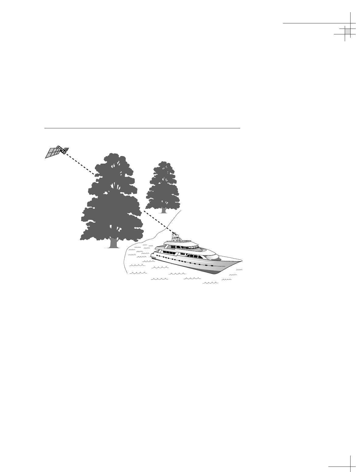
2 Receiving Satellite Signals
For TracVision G8 to receive satellite TV signals, the antenna
must have a clear line of sight to the satellite. If you only receive
intermittent signals or the antenna cannot find the satellite, check
around your vessel for any objects that could be blocking the
signal, such as other vessels, trees, buildings, other onboard
equipment, etc.
Figure 2
Satellite Blockage
You must also be located within the selected satellite’s coverage
area in order to receive its signal. Refer to your satellite television
service manual to check the viable coverage area. For your
convenience, KVH provides links to several web sites that offer satellite
coverage information. Simply go to our web site at: www.kvh.com/
footprint.
TracVision
54-0198
6
TracVision G8 Owner’s Manual - Guide to Operation
The satellite configuration on
your receiver must match the
satellite setting on the
TracVision G8 system.
Satellite A on the TracVision G8
must be the same satellite as
receiver Alternative 1 (or A, based
on your receiver) and must be
assigned the receiver DiSEqC 1
setting.*
Satellite B on the TracVision G8
must be the same satellite as
receiver Alternative 2 (or B, based
on your receiver) and must be
assigned the receiver DiSEqC 2
setting.*
Refer to your receiver user manual
for complete instructions for your
receiver.
*DiSEqC settings only apply to
European systems and DIRECTV
DSS Plus™receivers.
3 Turning On the System
To use the TracVision G8 system, follow the steps below. To
minimize the time it takes the antenna to acquire the satellite, do not
change the channel during this process.
1. Turn on the receiver and the television. (Refer to your
receiver user’s manual for complete operating
instructions for the receiver.)
2. Apply power to the TracVision G8 antenna.
3. Minimize turning the vessel for two minutes after turning
on the antenna to allow the antenna gyros to initialize
properly.
4 Changing Channels and
Switching to the Second Satellite
TracVision G8 can have a pair of satellites installed, either one of
which can be the active satellite selection. There are several
methods of selecting whether your TracVision G8 will track
Satellite A or Satellite B based upon your location, type of install,
receiver, and selected satellite service.
Europe and Australia
If you are not using a multiswitch, switching from one satellite to
the other is as easy as changing the channel using the receiver’s
remote control. TracVision G8 will automatically switch between
the two satellites as necessary to receive your selected channel. If
you are using a multiswitch, however, you will need to use the
MCU switching option described in “Switching Satellites Using the
MCU” on page 7.
North America
DIRECTV Subscribers
DIRECTV subscribers in certain regions of the United States will
require a DSS Plus™receiver to receive broadcasts from multiple
satellites. If connected to the antenna’s RF1 connector, the DSS
Plus receiver allows you to switch channels using the receiver’s
remote control. If you are a DIRECTV subscriber, but do not have
a DSS Plus receiver, or you are using a multiswitch, use the MCU
switching option described in “Switching Satellites Using the
MCU” on page 7.
Guide to Operation
54-0198 7
DISH Network
™
(EchoStar) and ExpressVu Satellite Subscribers
DISH Network and ExpressVu subscribers will need to use the
MCU switching option, as described in “Switching Satellites Using
the MCU.”
Latin America
In Latin America, including Mexico, satellite switching is
unnecessary because programming is broadcast from a single
satellite.
Switching Satellites Using the MCU
If you’re unable to switch between satellites using the receiver’s
remote control, use the MCU front panel buttons to select
between Satellite A and Satellite B. Press the left button to select
Satellite A and the right button to select Satellite B.
Figure 3
Switching Satellites Using the MCU
Tracking <SAT NAME>
Sat A Menu Sat B
Track Installed
Satellite A
Track Installed
Satellite B
Europe only:
Using the MCU to switch between
satellites disables the system’s
DiSEqC monitoring. You will not be
able to use the receiver/remote to
switch between satellites unless the
system is restarted.
54-0198
8
TracVision G8 Owner’s Manual - Guide to Operation
5 Watching Television
TracVision G8 will receive satellite TV signals whether your
vessel is in motion or at rest.
Cable Unwrap
If your vessel makes several consecutive circles in the same
direction, the antenna will rotate 720° before reaching the end of
its internal cable. If it does so, the system automatically unwraps
the cable by quickly rotating the dish in the opposite direction.
During this time, your TV picture will freeze momentarily.
Fine-Tuning
You might hear slight mechanical sounds from the antenna, as
the antenna moves continually in a circular motion to sweep
across the satellite’s peak signal. The signal strength is then fed
back to the control circuits to keep pointed in the direction of the
strongest signal.
Sleep Mode
When the vessel has come to a stop and holds its position for one
minute (e.g., at a dock), the antenna enters Sleep Mode, which
locks the antenna in place to conserve power. As soon as the
vessel moves beyond a 1° - 2° window, or the RF level changes
significantly, Sleep Mode automatically turns off and the system
begins tracking the satellite again (or enters Search mode to find
the satellite).
If you prefer, you may disable the
Sleep Mode function. Refer to
“Turning Sleep Mode On/Off” on
page 69
for details.
Guide to Operation
54-0198 9
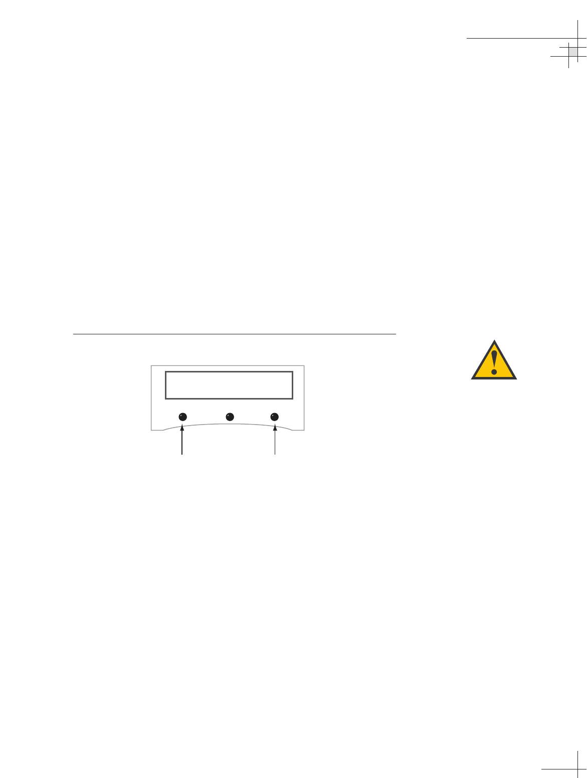
6 Using the MCU Interface
All TracVision G8 operations are controlled and monitored using
the MCU. An LCD display shows configuration data and three
buttons enable you to perform menu-driven tasks.
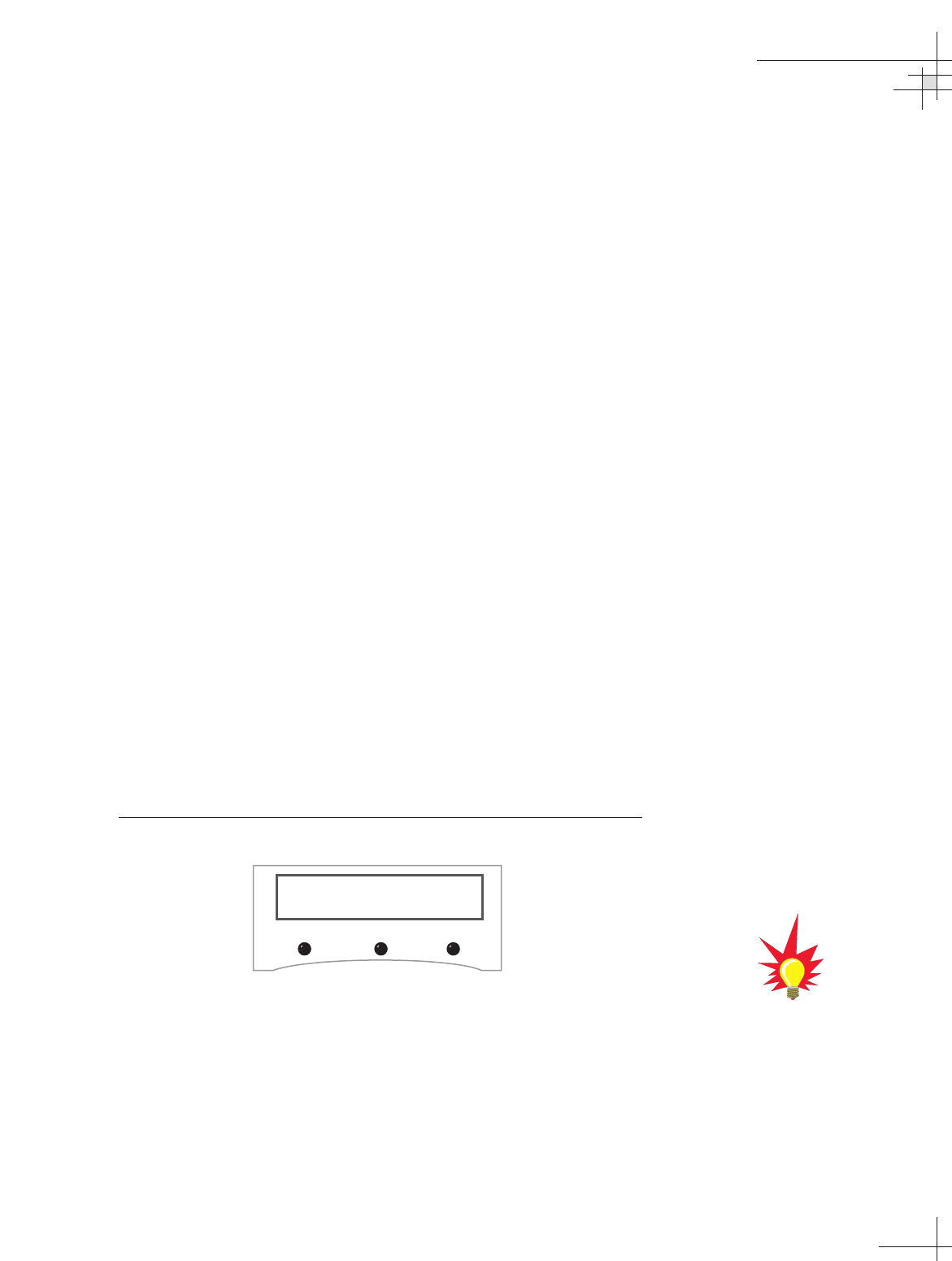
Figure 4
MCU Front Panel
During the TracVision G8 installation process, the satellite
selections should have been configured to your specifications as
detailed in the Guide to Technical Information. Once the system is
installed and functioning properly, the system will function
automatically.
However, there may be instances in which you need to access
certain settings or diagnostic tools via the MCU interface. To
assist you, KVH has provided the following information
resources:
Quick Reference Guide:
The quick reference guide on the inside front cover of this
manual illustrates the main display and the overall menu
structure, allowing you to easily and quickly navigate
among the MCU menus.
Section 3 in the Guide to Technical Information:
Section 3, “Using the MCU Interface,” on page 57 of the
Guide to Technical Information provides a detailed
explanation of every menu option and system
configuration setting. These menus should, for the most
part, be accessed by authorized technicians. The following
are the most commonly used menu functions:
Menu Function PurposeSee Page:
Install Satellite Install a satellite to track 62
Set Sleep On/Off Turn Sleep Mode on or off 69
Set Brightness Adjust the MCU display’s brightness 81
LCD Display
Buttons
Tracking <SAT NAME>
Sat A Menu Sat B

Guide to Technical Information
54-0198
11
Contents
1 Introduction . . . . . . . . . . . . . . . . . . . . . . . . . . . . . . . . . . . . . . . . . . . .13
2 Installation . . . . . . . . . . . . . . . . . . . . . . . . . . . . . . . . . . . . . . . . . . . . .19
3 Using the MCU Interface . . . . . . . . . . . . . . . . . . . . . . . . . . . . . . . . . .57
4 Troubleshooting . . . . . . . . . . . . . . . . . . . . . . . . . . . . . . . . . . . . . . . . .83
5 Maintenance . . . . . . . . . . . . . . . . . . . . . . . . . . . . . . . . . . . . . . . . . . . .93
Appendices . . . . . . . . . . . . . . . . . . . . . . . . . . . . . . . . . . . . . . . . . . . . . . . . . .121
Guide to Technical
Information
This guide explains how to install, troubleshoot, and maintain the
TracVision G8 system. For complete operating instructions, please refer
to the
Guide to Operation
at the front of this manual.

Introduction
54-0198
13
1 – Introduction
This section provides a basic overview of the TracVision G8 system. It
explains how the system works and describes the function of each
component.
Contents
1.1 System Overview . . . . . . . . . . . . . . . . . . . . . . . . . . . . . . . . . . . . . .15
1.2 System Components . . . . . . . . . . . . . . . . . . . . . . . . . . . . . . . . . . .17
1.3 Materials Provided with the TracVision G8 . . . . . . . . . . . . . . . . . .18
Introduction
54-0198
15
1.1 System Overview
A complete satellite TV system, illustrated in Figure 1-1, includes
the TracVision G8 antenna unit connected to the Master Control
Unit (MCU), a satellite TV receiver (integrated receiver/decoder,
or IRD), and a television set. While all basic programming and
first-level diagnostic functions are available through the MCU, a
laptop computer can be used to conduct advanced diagnostics.
System specifications are provided in Appendix A on page 123.
Figure 1-1
TracVision G8 System Diagram
Satellite Compatibility
The TracVision G8 satellite antenna is fully compatible with
Digital Video Broadcasting (DVB) satellites, as well as
DIRECTV‘s Digital Satellite Service (DSS) satellites.
In-motion Tracking
The TracVision G8 uses a state-of-the-art actively stabilized
antenna system. The antenna’s built-in global positioning system
(GPS) allows the system to calculate the precise azimuth and
elevation to the satellite from your vessel’s current location,
ensuring the shortest possible satellite acquisition time. Once the
satellite is acquired, the antenna gyros continuously measure the
heading, pitch, and roll of your vessel and send commands to the
antenna motors to keep the antenna pointed at the satellite at all
times.
TracVision
TracVision G8 systems equipped
with linear quad LNBs (used in
Mexico and Europe) can be
connected to four receivers using
four RF cables.
Receiver 2
Receiver 1
Options Purchased Separately
Master Control
Unit (MCU)
TracVision G8 Antenna
PC Diagnostics
9-36 VDC
90 Watts
RF
TV 1
TV 2
RF
Power/Data

Satellite Library
Your TracVision G8 includes a pre-programmed library of TV
satellites from around the world. When configuring the
TracVision G8, you may choose a pair of satellites from the
library to be active in the system and with your receiver. If the
satellite service you wish to receive is not listed in the satellite library,
you may add two additional satellites of your choice to the library.
North America
Any two of the North American satellites listed below can be
paired together, as long as the satellites are within range of the
antenna (standard circular dual LNB required):
Europe
Any two of the European satellites listed below can be paired
together, as long as the satellites are within range of the antenna
(linear quad LNB/feed tube assembly required):
Mexico
In Mexico, select the satellite listed below for Sky Mexico service
(linear quad LNB/feed tube assembly required).
• PAS_9
54-0198
16
TracVision G8 Owner’s Manual - Guide to Technical Information
TracVision G8’s default satellite
pairs are:
N. America (US DIRECTV):
DSS_101 & DSS_119
Europe:
ASTRA1 & HOTBIRDWB
Mexico (Sky Mexico):
PAS_9 & NONE
L. America (DIRECTV LA):
GALAXY3CN & NONE
• Astra1 • Sirius
• Astra2N •Thor
• Astra2S • Arabsat
• Hispasat • Nilesat
• HotbirdWB • Turksat
• Hotbird • Eutel_W3A
• DSS_72 • Echo_110
• DSS_101 • Echo_119
• DSS_110 • Echo_148
• DSS_119 • Expressvu
• Echo_61 • ExpressTV
Introduction
54-0198
17
Latin America
In Latin America, choose one of the satellites listed below for
DIRECTV Latin America (DLA) service (DLA circular dual LNB
required).
Australia
In Australia, you can pair together the two satellites listed below
(Linear quad LNB/feed tube assembly required).
1.2 System Components
Your TracVision G8 system includes the following components:
Antenna Unit
The antenna unit houses the antenna positioning mechanism, low
noise block converter (LNB), GPS, and three-axis sensor within a
molded ABS radome. Systems equipped with the linear quad
LNB include a skew control mechanism that automatically
adjusts the LNB’s skew to account for regional changes and
different satellite services. Power, signal, and control cabling from
belowdecks units are connected to the antenna at the rear of the
baseplate.
Master Control Unit (MCU)
The MCU is the user interface, providing access to the system
and its functions through an LCD and three buttons. The MCU
also serves as the system’s junction box, allowing the system to
use ship’s power, and supply and receive data to/from the
TracVision G8. The MCU can accept any power input between
9 and 36 volts DC; its power supply provides power to the
antenna and galvanically isolates the TracVision G8 system.
Satellite TV Receiver (IRD)
– Sold Separately
The receiver (purchased separately) receives satellite signals from
the antenna unit for signal processing and channel selection, and
sends the signals to the TV set for viewing. Please refer to the
user’s manual provided with your selected receiver for complete
operating instructions.
Before you can start watching
satellite TV using your TracVision
antenna, you will need to activate
your receiver. Refer to
Section 2.6,
“Activating/Programming the
Receiver,” on page 40
for details.
• Galaxy3CN • Galaxy3CS
• Optus_B1 • Optus_B3
54-0198
18
TracVision G8 Owner’s Manual - Guide to Technical Information
1.3 Materials Provided with the
TracVision G8
Table 1-2 lists the components and materials in the TracVision G8
shipping carton.
Table 1-2
TracVision G8 Packing List
Component KVH Part No.
Antenna unit 02-1262-01†
02-1262-03††
02-1262-04†††
02-1262-05††††
Master control unit (MCU) 02-1265
Installation kitpack 72-0127
Data/power cable, 100 ft. (30 m) 32-0744-0100
TracVision G8 Owner’s Manual
54-0198
†Standard circular dual LNB (configured for North America)
†† DLA circular dual LNB (configured for DIRECTV Latin America)
††† Linear quad LNB (configured for Europe)
†††† Linear quad LNB (configured for Sky Mexico)
For a list of items supplied in the
kitpack, see Table 2-3 on page 22.

Installation
54-0198
19
2 – Installation
This section explains how to install, configure, and test the
TracVision G8 system. Follow the simple procedures in this section
sequentially to ensure a safe and effective installation.
Contents
2.1 Planning the Installation . . . . . . . . . . . . . . . . . . . . . . . . . . . . . . . .21
2.2 Mounting the TracVision Antenna . . . . . . . . . . . . . . . . . . . . . . . . .26
2.3 Connecting the Receiver(s) . . . . . . . . . . . . . . . . . . . . . . . . . . . . . .31
2.4 Wiring the MCU . . . . . . . . . . . . . . . . . . . . . . . . . . . . . . . . . . . . . . .35
2.5 Mounting the MCU . . . . . . . . . . . . . . . . . . . . . . . . . . . . . . . . . . . .38
2.6 Activating/Programming the Receiver . . . . . . . . . . . . . . . . . . . . . .40
2.7 Installing Satellites Using the MCU . . . . . . . . . . . . . . . . . . . . . . . .42
2.8 Checking Out the System . . . . . . . . . . . . . . . . . . . . . . . . . . . . . . .52
2.9 Changing Geographic Location . . . . . . . . . . . . . . . . . . . . . . . . . . .54
Installation
54-0198
21
2.1 Planning the Installation
Who Should Install the TracVision G8?
KVH recommends that a KVH-authorized technician install the
TracVision G8 system. Installers should have experience
installing electronic equipment on a vessel.
Materials and Equipment Required for Installation
Before you begin installing the TracVision G8 system, you need to
verify that you have all of the following tools and materials:
• Electric drill and 1⁄2" (13 mm) drill bit
• 17 mm socket wrench and 9⁄16" open-end wrench
• Flat head and Phillips screwdrivers
• Light hammer; center punch; tape; scriber/pencil
• Wire strippers
•A PC with KVH Flash Update Wizard or Windows
HyperTerminal installed
• Quick-tripping circuit breaker or fuse rated for 15 amps
•RG-11 or RG-6 cable(s) with F-type connectors (refer to
Table 2-1 to determine the number of RF cables needed)
Table 2-1
Number of RF Cables to Connect to the Antenna
Connecting to: # RF Cables
System with Circular Dual LNB
One receiver 1
Two receivers 2
Two or more receivers 2*
System with Linear Quad LNB
One receiver 1
Two receivers 2
Three receivers 3
Four receivers 4
More than four receivers 4*
* Multiswitch required. Follow manufacturer’s guidelines.
RG-11 or RG-6 cable with F-type
connectors is required for all RF
wiring. Use of any other cable will
result in degraded performance.
Use RG-6 cable for distances up to
75 ft (23 m); use RG-11 cable for
distances greater than 75 ft (23 m).
The KVH warranty does not cover
degraded performance due to
improper wiring.
You may want to connect four RF
cables to the antenna in all cases.
That way, if a receiver is added (or
the system is converted from North
American to European use) in the
future, no additional RF cables will
need to be run.
Plan the entire installation before
proceeding! Take into account
antenna unit placement, cable
running distances between units,
and accessibility to the equipment
after installation.
If you are prewiring the system,
be sure to route the N-type
connector end of the data/power
cable to the antenna location and
the F-type connector end to the
belowdecks MCU (see Figure 2-7
on page 28).
• Power cable to connect the MCU to ship’s power
(Table 2-2 provides proper gauge and length specifications
for a 12V supply. The system will not work if the MCU
receives less than 9V).
Table 2-2
Recommended Power Cable Specifications
Cable Length Cable Gauge
to 40 ft (12 m) 12 AWG (1.5 mm2)
up to 70 ft (21 m) 10 AWG (2.5 mm2)
Kitpack Contents
The kitpack packaged with your system contains hardware and
other materials that will be needed to complete the installation.
Ensure that the kitpack contains all of the items listed below.
Table 2-3
Kitpack Contents
Part Part # Qty.
M10 x 1.5 x 50 mm hex head bolts 14-0342-50 4
M10 flat washers 14-0344-10 4
M10 lock washers 14-0343-10 4
M4 x 0.7 x 8 mm pan-head Phillips screws 14-0075-08 6
Plastic screw covers 19-0088 8
Rear logo plate 20-0885-02 1
Power connector plug 23-0497-02 1
Receiver ground cable 32-0583-50 1
PC cable
(for diagnostics)
32-0628-06 1
PC cable gender changer 23-0517-09 1
Flush mount MCU bracket 20-0667 1
Velcro self-adhesive backings 19-0146 4
Velcro washers 19-0147 4
#4-24 thread-forming screws 14-0150-06 4
Tie-wraps 22-0006 5
#8 type A screws 14-0047-08 4
#8 lock washers 14-0038 4
#6-32 x 1⁄2" pan head screws 14-0029-08 2
54-0198
22
TracVision G8 Owner’s Manual - Guide to Technical Information
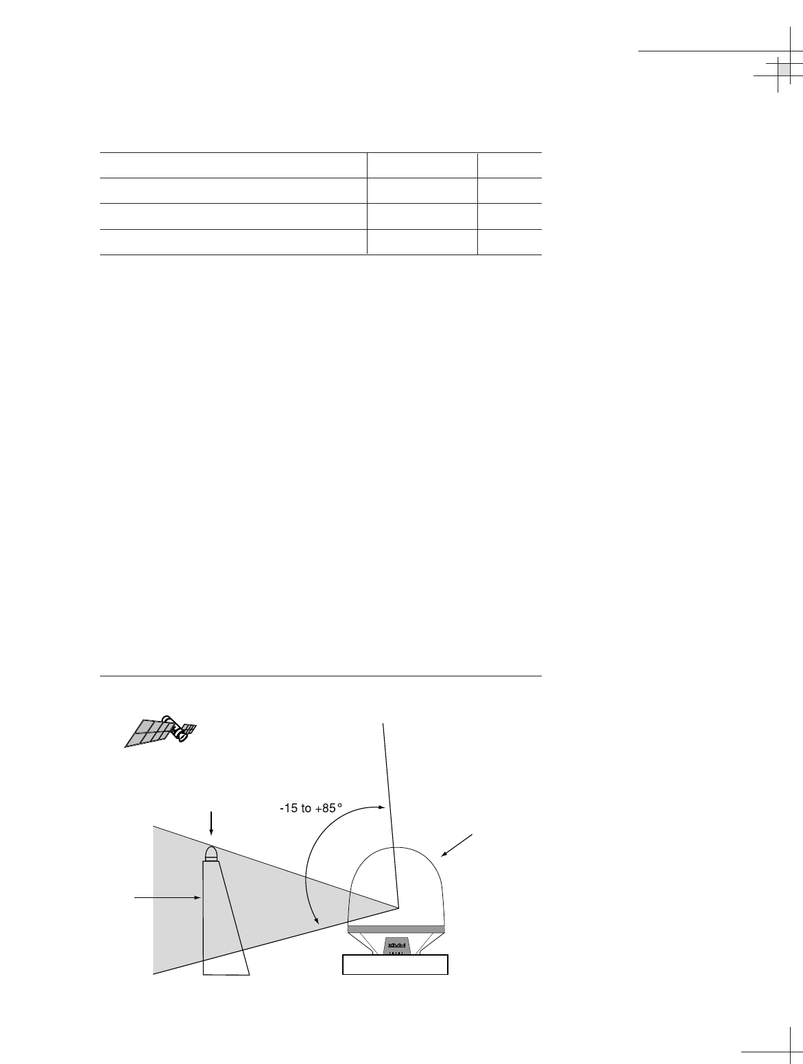
Table 2-3
Kitpack Contents (continued)
Part Part # Qty.
#6 flat washers 14-0024 2
Small Ferrite Coil 29-0088 1
Large Ferrite Coil 29-0090 1
F-type connector 23-0213 1
Choosing Component Locations
When choosing component locations, first keep in mind
accessibility and cable lengths between units. For example, since
the data/power cable is 100 ft (30 m) long, the MCU must be
located within 100 ft (30 m) of the antenna. The major
considerations in locating system components are noted below.
Choosing the Best Location for the TracVision Antenna
There are several factors to consider when choosing the location
for the TracVision antenna.
• Since the TracVision antenna requires a clear view of the
sky to receive satellite signals, the ideal antenna site has
an unobstructed view of the horizon/satellite all around.
The less blockage, the better the system performs.
• Keep the antenna clear of any obstructions above decks.
The antenna requires a -15º to +85º look angle to receive
satellite signals.
Figure 2-1
Antenna Blockage
Installation
54-0198
23
Blocked!
TracVision Antenna
Vessel Platform
Mast

• To minimize tracking errors, place the antenna unit as
close as possible to the intersection of the vessel’s fore-
and-aft centerline and midships. In addition, do not
mount the antenna too high off the water (limit height
above the waterline to less than half the vessel length).
•The mounting surface should be flat and strong enough to
carry the complete assembly (85 lbs/ 38.6 kg). To prevent
warpage to the antenna baseplate, make sure that the
mounting surface is rigid so that it cannot flex when the
vessel vibrates. If necessary, add a strength member to the
mounting site to stiffen it.
• Be sure to account for the height and base dimensions (see
Figure 2-2 on the following page). Also be sure to leave
enough space outside the access hatch to allow a
technician to remove the hatch screws and perform
maintenance through the hatch.
•Maintain at least four feet (1.3 m) separation between the
antenna and any magnetized materials, large ferrous
masses, cranes, engines, derricks, other antennas, cables
carrying high amperage direct current, or battery banks.
Take extra care when mounting the antenna on a steel
vessel; use an aluminum, brass, plastic, or wood (NOT
steel or iron) platform to position the antenna at least four
feet (1.2 m) above and six feet (1.8 m) away from the steel
surface.
•Be alert for devices that change their magnetic
characteristics when in use, such as CRTs (computer and
TV screens), radar magnetrons, electric winches,
loudspeakers, windshield wipers, and other devices with
DC motors. The antenna’s internal sensor cannot
compensate for changing magnetic fields created by these
devices.
Radar Concerns
The TracVision antenna must be kept out of line with nearby
radars, as their energy levels (from both the main beam and its
side lobes) may overload the antenna’s front-end circuits. In an
ideal installation, the antenna is mounted four feet (1.2 m) above
and four feet (1.2 m) away from the radar (measured from the
center of the antenna dome to the center of the radar).
The best placement for the TracVision antenna is above the radar.
However, if there will be a significant horizontal separation
between the radar and TracVision dome (i.e., at least 8 to 10 feet
(2.4 to 3 meters)), the TracVision antenna can be placed below the
radar as there will be little chance of signal blockage.
54-0198
24
TracVision G8 Owner’s Manual - Guide to Technical Information
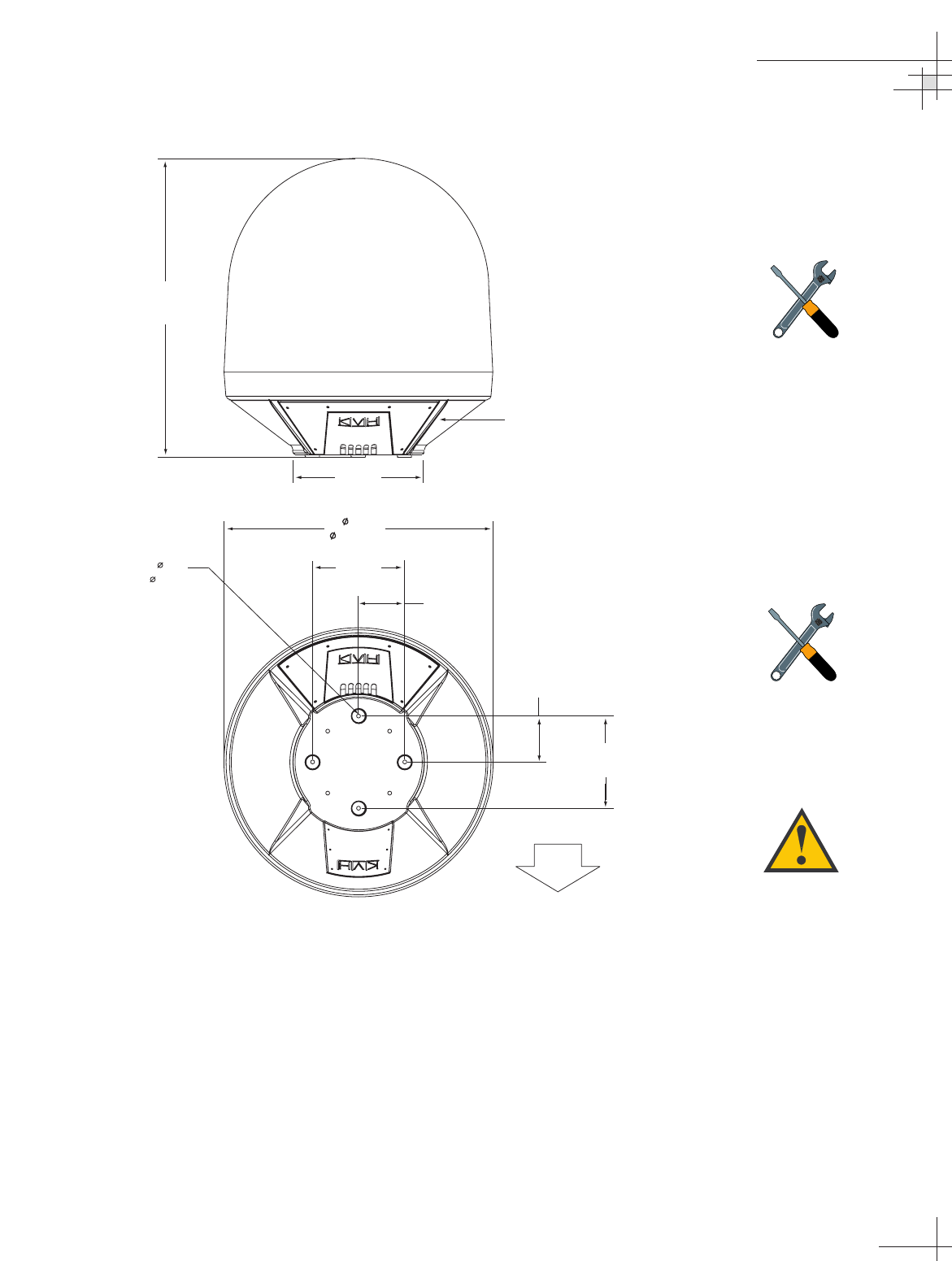
Figure 2-2
Antenna Unit Dimensions
Choosing the Best Location for the MCU
• The MCU should be mounted in a dry location, allowing
enough room at the back for connecting system cables.
Also be sure to mount the MCU in a well-ventilated area
to prevent overheating, which will damage the system.
• The MCU should be placed so that the LCD display is
visible and the buttons are accessible to the user.
• The MCU is not susceptible to magnetic interference and
does not need to be mounted on a level surface.
Installation
54-0198
25
FWD
38.86"
(987 mm)
4x .50"
(4x 13 mm)
35"
( 889 mm)
12"
(305 mm)
6"
(152 mm)
6"
(152 mm)
12"
(305 mm)
Access Hatch
17"
(432 mm)
The radome exterior is treated
with a special finish selected for
compatibility with the dome material
and transparency to the satellite
signals. Application of additional
paints or finishes WILL degrade
performance, potentially beyond
acceptable limits.
A full-size template of the baseplate
mounting holes has been provided
at the back of this manual.
Four small holes have been drilled
into the bottom of the baseplate to
ensure that any moisture that
enters the antenna unit is able to
drain. Be sure these drain holes do
not become blocked.
2.2 Mounting the TracVision
Antenna
To mount the antenna to the vessel, follow the steps below.
1. Make sure that you have chosen a suitable mounting
location based upon the guidelines in “Choosing the Best
Location for the TracVision Antenna” on page 23.
2. Using the template provided at the back of this manual or
the dimensions shown in Figure 2-3, lay out the four
mounting bolt holes. Make certain that the “Forward”
arrow is parallel with the vessel’s centerline and pointed
toward the bow.
Figure 2-3
Antenna Mounting Holes Layout
3. Drill the four 1⁄2" (13 mm) bolt holes following the layout
in Step 2.
4. If mounting the antenna on a deck:
Mark a location aft of the antenna for the cable access
hole. The hole must be large enough to accommodate the
data/power cable and all required RF cables (see Table 2-1
on page 21 to determine the number of RF cables required). Cut
out the access hole and smooth the edges of the hole to
protect the cables.
5. Remove the antenna unit from its shipping carton.
54-0198
26
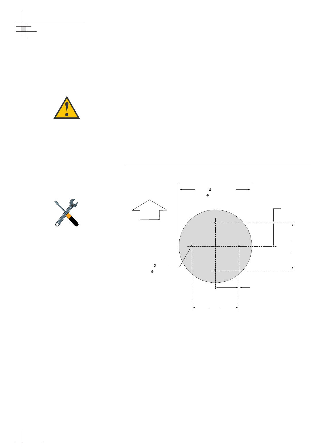
TracVision G8 Owner’s Manual - Guide to Technical Information
FWD
4 x 0.5"
(4 x 13 mm)
12"
(305 mm)
6"
(152 mm)
12"
(305 mm)
6"
(152 mm)
Baseplate Footprint
17"
( 432 mm)
A full-size template of the baseplate
mounting holes has been provided
at the back of this manual.
For the antenna to work properly,
the “Forward” arrow MUST be
parallel with the vessel’s centerline
and pointed toward the bow.
6. Remove the eight screws securing the radome to the
baseplate. Carefully lift the radome straight up until clear
of the antenna assembly and set it aside in a safe place. If
you bring the radome topside, secure it with a lanyard to
prevent it from falling overboard.
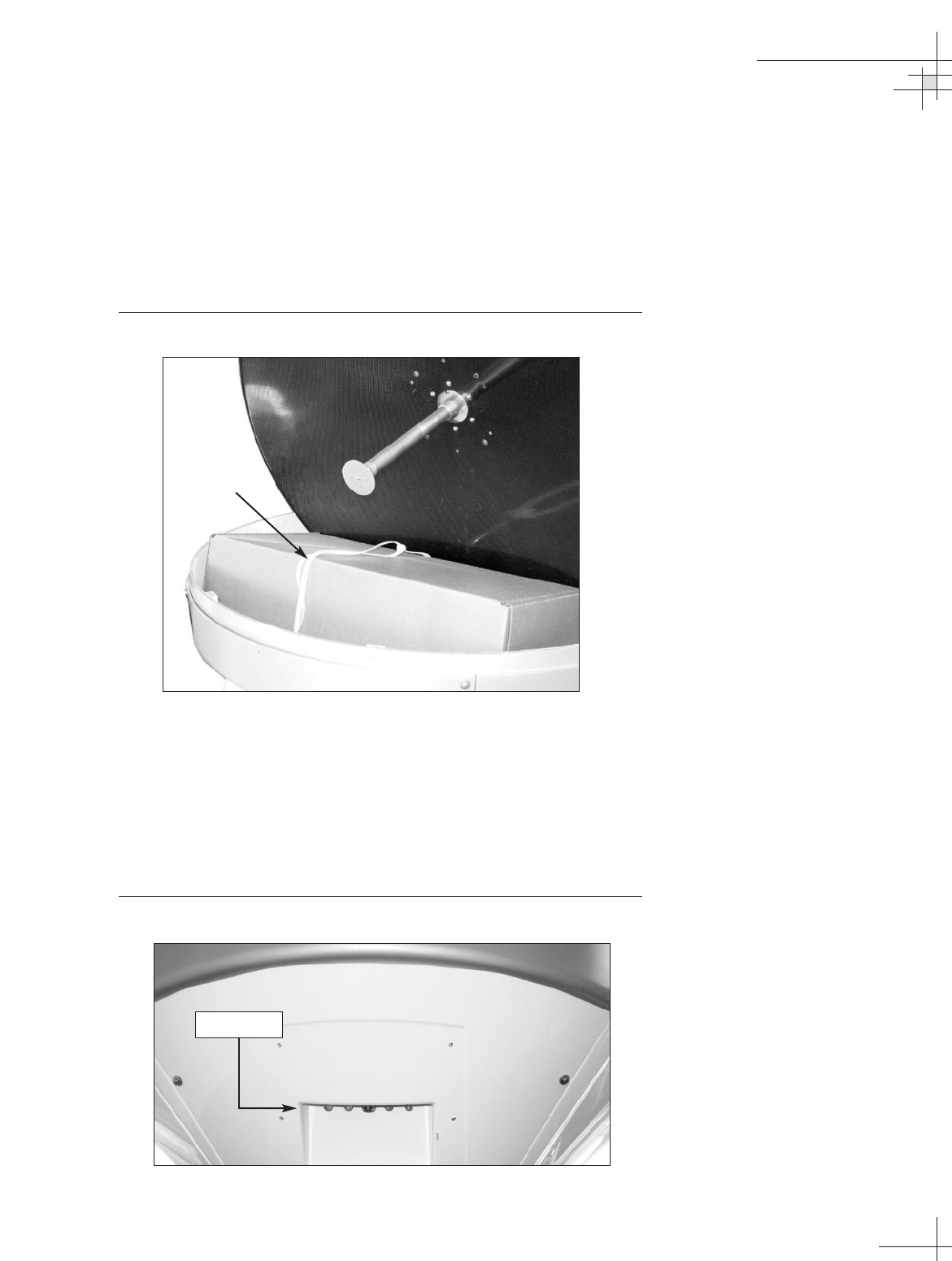
7. Remove the tie-wrap securing the MCU/kitpack box to
the antenna baseplate. Remove the box.
Figure 2-4
MCU/Kitpack Box
8. Inspect the antenna unit for any signs of shipping
damage.
9. Position the baseplate assembly in place over the
mounting holes, with the baseplate’s connectors (shown
in Figure 2-5) facing the stern. Ensure that all mounting
holes line up and make any necessary adjustments.
Figure 2-5
Location of Baseplate Connectors
Installation
54-0198
27
Tie-wrap
Connectors
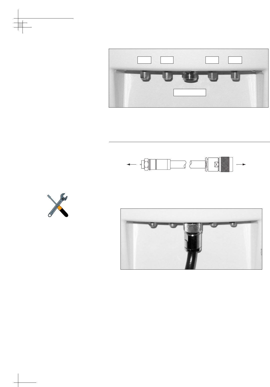
Figure 2-6
Baseplate Connectors
10. Connect the N-type connector end of the data/power
cable to the baseplate, as shown in Figures 2-7 and 2-8.
Figure 2-7
Data/power Cable Connectors
Figure 2-8
Connecting the Data/Power Cable
54-0198
28
TracVision G8 Owner’s Manual - Guide to Technical Information
RF3 RF1 RF2 RF4
Data/Power
F-type Connector N-type Connector
To MCU To Antenna
Be sure to properly align the
data/power cable with the
baseplate connector before
tightening. Connecting the cable at
an angle may damage the cable’s
center tines.
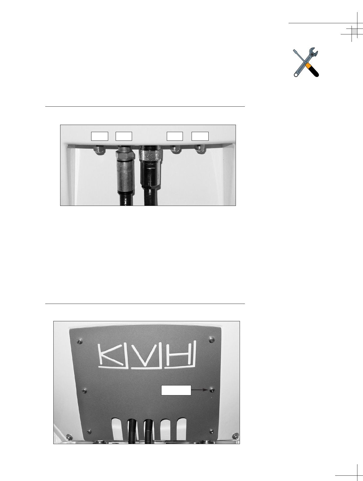
11. Using a 9⁄16" wrench, connect the RF cable(s) from
belowdecks to the baseplate. If you connect more than
one RF cable, label both ends of each RF cable to match its
antenna baseplate connector (RF1, RF2, RF3, or RF4).
Figure 2-9 shows an RF cable connected to the RF1
connector.
Figure 2-9
Connecting the RF1 Cable
12. Route the other ends of the data/power and RF cables
belowdecks (if mounting the antenna to the deck, route
the cables into the cable access hole that you cut out in
Step 4).
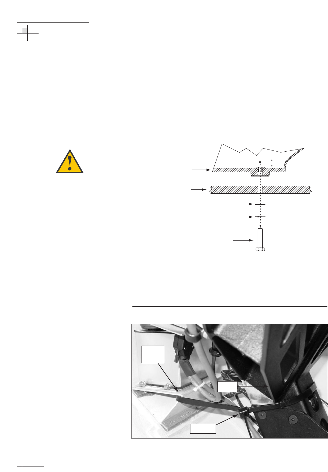
13. Place the rear logo plate over the cables, so that each cable
exits the proper opening (see Figure 2-10). Using the six
M4 screws supplied in the kitpack, attach the logo plate to
the baseplate as shown in Figure 2-10.
Figure 2-10
Attaching the Logo Plate
Installation
54-0198
29
Do NOT use teflon gel on the cable
fittings as it reduces signal strength
at higher frequencies.
RF3 RF1 RF2 RF4
M4 Screw
14. Place the antenna baseplate over the mounting holes
drilled in the foundation, ensuring the connectors face the
stern.
15. At each of the four baseplate mounting holes, place an
M10 lock washer and flat washer on an M10 bolt and
insert the bolt into the hole from below, as shown in
Figure 2-11. Tighten all four bolts securely until the four
feet are bottomed against the mounting surface.
Figure 2-11
Bolting the Antenna Unit to the Deck (Side View)
16. Unfasten the tie-wrap securing the antenna frame to the
sensor bracket (release the tab using a flat-head screwdriver).
Save the tie-wrap in case the antenna needs to be
reshipped someday.
Figure 2-12
Antenna Frame Shipping Restraint
54-0198
30
TracVision G8 Owner’s Manual - Guide to Technical Information
M10 x 50 mm Bolt
Antenna Unit Base
Deck
M10 Flat Washer
M10 Lock Washer
10 mm max.
Tie-wrap
Sensor
Bracket
Frame
Ensure the mounting screws do not
extend further than 0.4" (10 mm)
into the antenna baseplate.
Inserting the screws any further will
damage the antenna.
17. Reinstall the radome. Secure in place with the eight
screws you removed in Step 6. Install a protective plastic
screw cap from the kitpack over each screw.
2.3 Connecting the Receiver(s)
Connecting the RF Cable(s)
Each RF cable must be an RG-11 (75 ohms) or RG-6 (75 ohms)
cable fitted with F-type connectors. The RF cables should already
be connected to the antenna baseplate (see Step 11 of Section 2.2,
“Mounting the TracVision Antenna,” on page 29). The following
sections explain how to connect the RF cable(s) to your satellite
TV receiver(s).
To connect the TracVision antenna to your receiver(s), choose one
of the following configurations (based on the number of receivers
you will connect to the antenna):
Option 1 - Connecting One Receiver
Option 2 - Connecting Two Receivers
Option 3 - Connecting Three or More Receivers
Option 1 - Connecting One Receiver
One end of the RF cable should already be connected to the RF1
plug on the TracVision antenna. Connect the other end of the RF1
cable to the receiver plug labeled “LNB,” “ANT/SAT,” or
“SATELLITE IN.”
Option 2 - Connecting Two Receivers
Two RF cables should already be connected to the RF1 and RF2
plugs on the TracVision antenna. Connect the other ends of these
RF cables to the plug labeled “LNB,” “ANT/SAT,” or
“SATELLITE IN” on both receivers.
The receiver that is connected to the RF1 cable controls which
satellite the antenna is tracking. This is the master receiver. The
receiver connected to RF2 can select different channels on that
satellite but not change the satellite selection itself.
Installation
54-0198
31
Before you connect an RF cable to
a receiver, turn on the receiver and
TV and verify that there is no AC
voltage present on the receiver’s
input connector, measured between
center conductor and shield. If AC
voltage is present on the connector,
DO NOT connect the RF cable until
you have corrected the problem.
This is a potentially dangerous
condition that will damage the
antenna’s electronics.
Option 3 - Connecting Three or More Receivers
(System Equipped with Circular Dual LNB)
To connect three or four receivers to the TracVision antenna, you
will need to install an active multiswitch (Channel Master model
6214IFD or equivalent) between the antenna and the receivers.
Two RF cables should already be connected to the RF1 and RF2
plugs on the TracVision antenna. Figure 2-13 shows a typical
wiring arrangement for three or four receivers. Mount the
multiswitch unit in accordance with the manufacturer’s
instruction sheet.
Figure 2-13
Single Multiswitch Installation (Circular Dual LNB
System)
1. Connect the RF cable labeled "RF1" to the multiswitch
input labeled "LNB RHCP +13V.”
2. Connect the RF cable labeled “RF2” to the multiswitch
input labeled "LNB LHCP +18V.”
3. Connect the multiswitch outputs to individual receiver
inputs. Use RG-11 or RG-6 cable with F-type connectors
for all RF connections. Terminate all unused output
connectors with 75 ohm DC blocks (Channel Master
#7184, Radio Shack #15-1259 or equivalent).
54-0198
32
TracVision G8 Owner’s Manual - Guide to Technical Information
Multiswitch
DC In RHCP
+13v
VHF/UHF LHCP
+18v
Out 1 Out 2 Out 3 Out 4
DC Power
RF1 RF2
Receiver #2 Receiver #3 Receiver #4
Receiver #1
The use of an active multiswitch will
interfere with the 22 KHz tone sent
by DIRECTV DSS Plus
™
receivers
to the antenna. As a result, the
antenna will not receive the signal
to change satellites when you
change channels using your
DIRECTV DSS Plus remote.
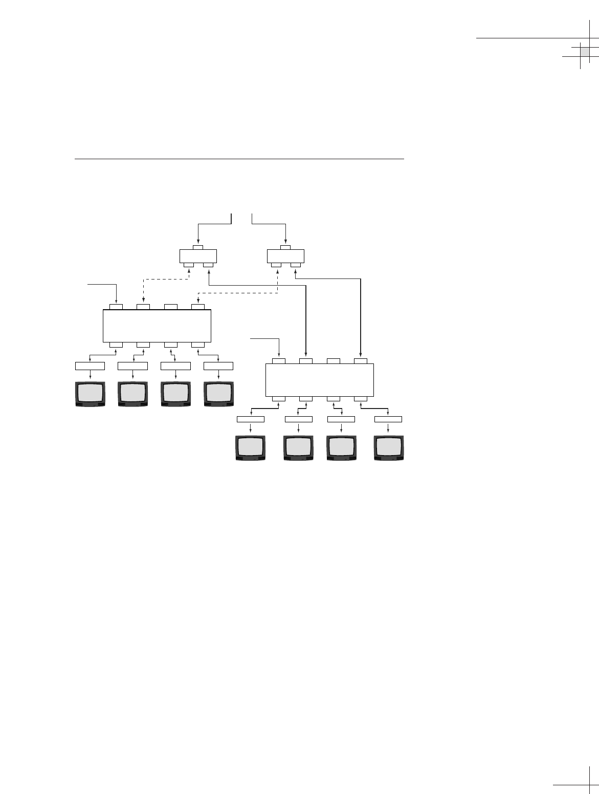
Multiple Multiswitch Installation
If you need to connect more than four receivers to the TracVision
antenna, you may carry out a multiple multiswitch installation,
as shown in Figure 2-14.
Figure 2-14
Multiple Multiswitch Installation (Circular Dual
LNB System)
Installation
54-0198
33
Multiswitch
DC In RHCP
+13v
VHF/UHF LHCP
+18v
Out 1 Out 2 Out 3 Out 4
DC Power
Multiswitch
DC In RHCP
+13v
VHF/UHF LHCP
+18v
Out 1 Out 2 Out 3 Out 4
DC Power
Receiver #5 Receiver #6 Receiver #8Receiver #7
RF Splitters/
Power Dividers
Receiver #2 Receiver #3 Receiver #4
RF1 RF2
Receiver #1
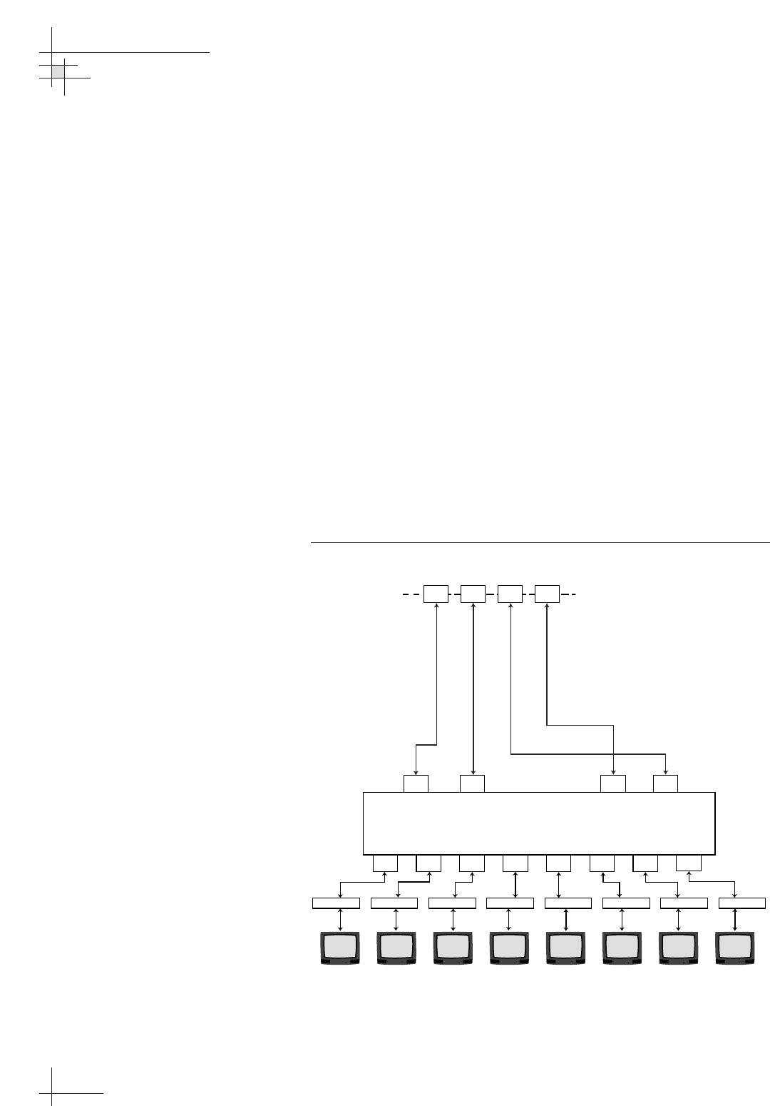
Option 3 - Connecting Three or More Receivers
(System Equipped with a Linear Quad LNB)
Systems equipped with a linear quad LNB have four RF outputs
that can be connected to individual receivers.
Connecting Three or Four Receivers
To connect a third receiver, a third RF cable should already be
connected to the RF3 plug on the TracVision antenna. Connect
the other end of the RF3 cable to the plug labeled “LNB,”
“ANT/SAT,” or “SATELLITE IN” on the third receiver. To
connect a fourth receiver, use the fourth RF cable, which should
already be connected to the RF4 plug on the antenna.
Connecting More than Four Receivers
To connect more than four receivers, you will need to install an
active multiswitch that generates a 22 KHz tone (for example,
Spaun models 5602NF or 5802NF). Connect the multiswitch unit
in accordance with the manufacturer’s instructions. Figure 2-15
shows an example of a European multiswitch configuration.
Figure 2-15
Multiswitch Installation (Linear Quad LNB System)
54-0198
34
TracVision G8 Owner’s Manual - Guide to Technical Information
Active Multiswitch
Vert. Hor. Vert./mod. Hor./mod.
Out 1 Out 2 Out 3 Out 4 Out 5 Out 6 Out 7 Out 8
Receiver #2Receiver #1 Receiver #3 Receiver #6 Receiver #7 Receiver #8Receiver #4 Receiver #5
5-50 kHz
RF4 RF3 RF2 RF1
RF cables
supplied by customer
RF4 RF3 RF2 RF1
2.4 Wiring the MCU
All other wiring for the TracVision system connects at the rear
panel of the MCU.
For the TracVision system to work properly, you must connect
the following cables to the MCU:
• Antenna data/power cable
• Vessel power cable
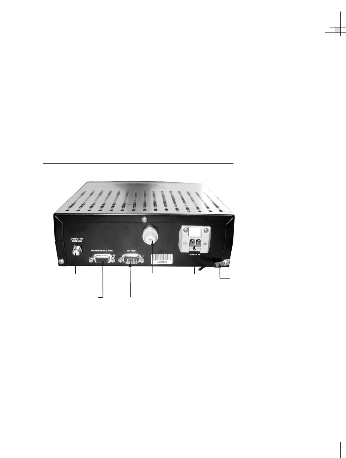
Figure 2-16 shows the MCU’s rear panel connectors. Refer to this
figure when wiring components to the MCU.
Figure 2-16
MCU Rear Panel
Connecting the Antenna Data/Power Cable
Connect the antenna data/power cable to the data/power
connector on the MCU’s rear panel (see Figure 2-16). Do not
overtighten; finger-tight is sufficient.
Installation
54-0198
35
Antenna
Data/Power
Vessel Power
+ -
Maintenance Port
(for PC diagnostics)
RF PCB Software Flashing Port
(technician’s use only)
Fuse MCU Ground Wire
Connecting Vessel Power and the MCU Ground Wire
Short circuits may result in severe electrical shock or burns. Turn
off vessel power and test the circuit to ensure that no power is
present before connecting any power cables. Do NOT reapply
power until all system wiring is completed.
The TracVision G8 system requires a 9-36 VDC power input.
Since it does not have a dedicated power control (ON/OFF
switch), a quick-tripping circuit breaker or fuse should be
installed between vessel power and the MCU. Circuit overload
protection should be rated for 15 amperes. For recommended
power cable specifications, refer to Table 2-2 on page 22.
A power connector plug has been supplied in the kitpack to
make connecting power to the MCU a snap. To connect vessel
power and the ground wires, follow the steps below.
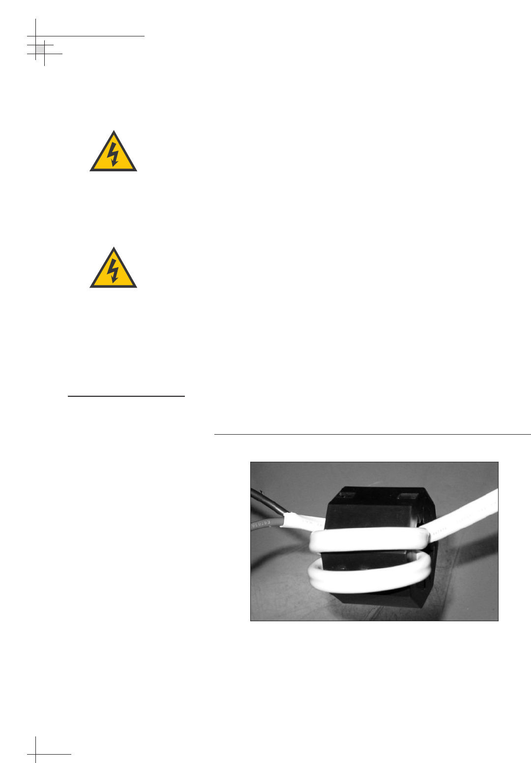
1. A large ferrite coil is supplied in the kitpack to help
reduce conducted emissions from the vessel power cable.
This ferrite coil needs to be installed for the system to
comply with CE standards. To install the ferrite coil, make
two loops in the vessel power cable and clamp the ferrite
coil around the loops (see Figure 2-17). The cable, with
both positive and negative wires, must pass through the
ferrite coil three times to be effective.
Figure 2-17
Large Ferrite Coil Clamped onto Vessel Power Cable
54-0198
36
TracVision G8 Owner’s Manual - Guide to Technical Information
KVH recommends a 12 VDC
(5 amps) or a 24 VDC (2.5 amps)
power input to the TracVision G8
(supplying not less than 9 VDC at
the MCU). Power supplied to the
TracVision G8 MUST NOT exceed
36 VDC or the TracVision power
supply will suffer serious damage!
Before connecting the power cable,
turn off vessel power and test the
circuit to ensure that no power is
present.
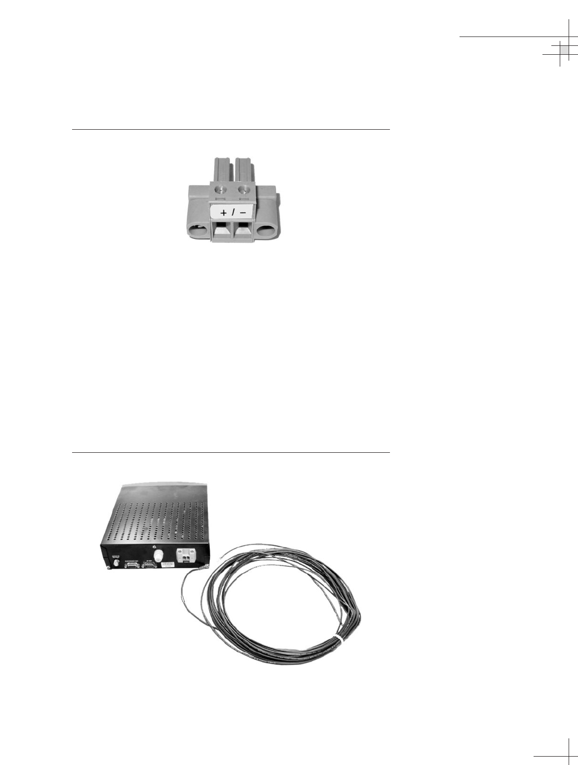
2. Find the power plug provided in the kitpack and insert
your vessel power wires into the plug’s (+) and (-)
terminals (see Figure 2-18).
Figure 2-18
Power Plug
3. Secure the wires in place by tightening the plug’s terminal
screws.
4. After inserting and securing the wires, tug gently to
ensure that the connections are solid. Also make certain
that the wire insulation is not pinched in the connector.
5. Plug the power connector plug into the power jack on the
MCU’s rear panel (see Figure 2-16 on page 35).
6. Secure the plug in place with the two retaining screws.
7. The MCU has a ground wire preattached to one of its
retaining screws (see Figure 2-19). Be sure to connect this
wire to a suitable ground.
Figure 2-19
MCU Ground Wire
Installation
54-0198
37
2.5 Mounting the MCU
Mount the MCU using either of the following options:
Option 1 - Velcro Fastening on a Horizontal Surface
Option 2 - Flush-mounting
The following sections describe how to mount the MCU for both
of these options.
Option 1 - Velcro Fastening on a Horizontal Surface
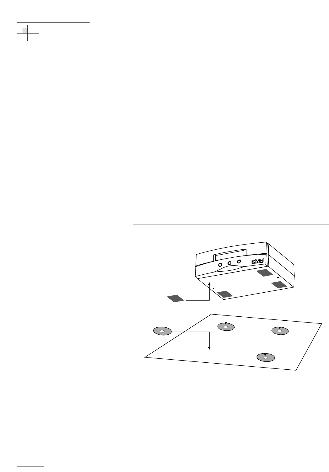
1. Choose a location based upon the guidelines in “Choosing
the Best Location for the MCU” on page 25.
2. Remove the four squares of Velcro fabric from the kitpack.
Clean the bottom of the housing with a mild detergent
and water to remove oils, etc. Peel the protective backing
from the squares and apply them to the bottom of the
housing at each of the four corners (see Figure 2-20).
Figure 2-20
Mounting the MCU with Velcro Attachments
3. Position the four Velcro hook disks where the MCU will
be mounted. Drill screw holes for the disks and secure in
place with the #4-24 screws supplied in the kitpack.
4. Press the MCU firmly into place so that the loop material
engages the hook disks.
54-0198
38
TracVision G8 Owner’s Manual - Guide to Technical Information
Fabric Strips
Hook Disks
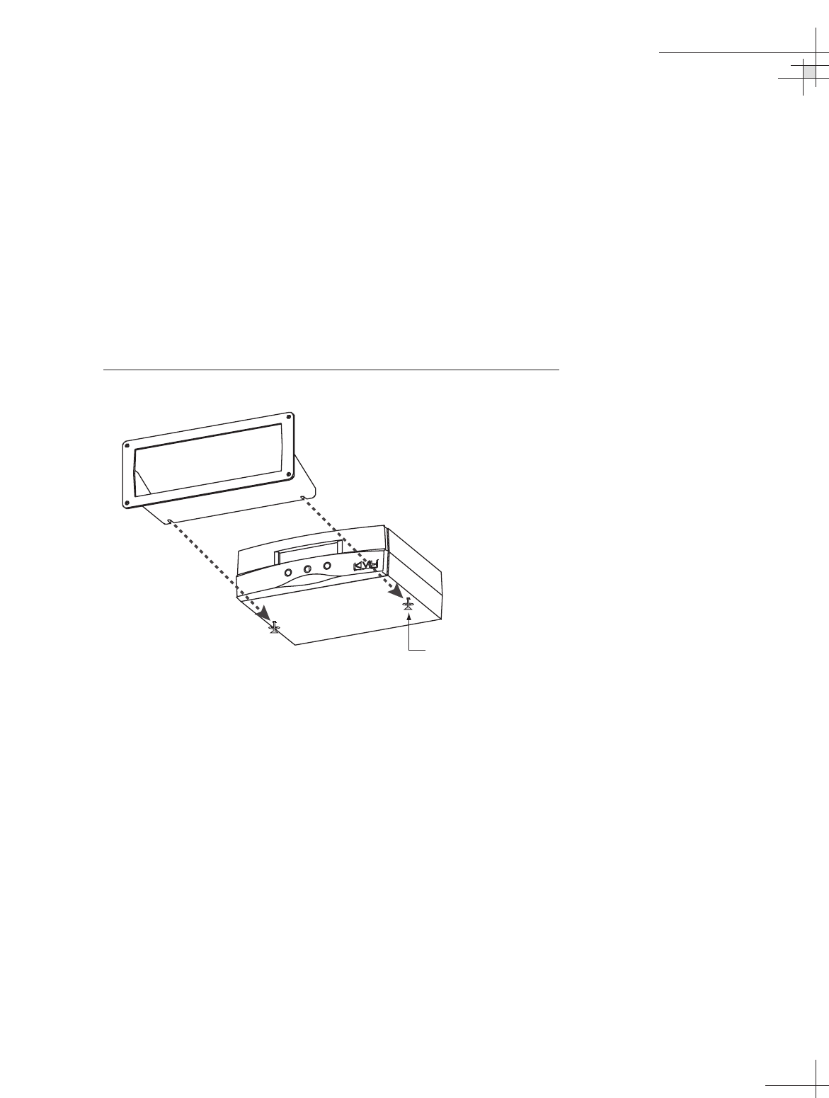
Option 2 - Flush-mounting
1. Choose a location based upon the guidelines in “Choosing
the Best Location for the MCU” on page 25.
2. A template has been provided in Appendix B on page 125 as
a guide to mark and cut the proper hole for the flush
mount bracket. Cut the hole and make certain the bracket
and MCU will fit easily.
3. At the two holes in the bottom of the MCU, place a #6 flat
washer on a #6-32 screw and insert the screw into the hole
from below, as shown in Figure 2-21. Do not tighten the
screws yet; just a few turns is sufficient.
Figure 2-21
Securing the MCU to the Flush Mount Bracket
4. Slide the flush mount bracket backward onto the MCU
until the two notches meet the screws as shown in
Figure 2-21.
5. Tighten the screws to secure the MCU to the bracket.
6. Insert the MCU and bracket into the mounting hole and
secure the unit to the mounting surface with the #8 (black)
screws and #8 washers supplied in the kitpack.
Installation
54-0198
39
#6-32 x 1/2"
Pan-head Screw
and Flat Washer (x2)

54-0198
40
TracVision G8 Owner’s Manual - Guide to Technical Information
2.6 Activating/Programming the
Receiver
Before it can be used, your satellite TV receiver must be activated
and/or programmed, as described below.
DIRECTV Activation
KVH makes it easy to activate a DIRECTV receiver. Just call KVH
at 1-888-584-4163 and select the TracVision Product Activation
Department (Monday - Friday, 8:30 a.m. - 5:00 p.m. EST).
DISH Network Activation
To activate a DISH Network receiver, please call DISH Network
directly at 1-800-333-DISH (3474).
Other Receiver Activations
Please refer to the user manual that accompanied your receiver
for activation instructions.
Programming European or Australian Receivers
Before the TracVision G8 system can be used in Europe or
Australia, the receiver must be programmed to receive signals
from the selected DVB satellite services. Programming is
conducted using menu selections displayed on the TV screen.
Please refer to your receiver owner’s manual for specific
instructions.
Table 2-4 provides some key data for use when programming
the receiver.
Table 2-4
Key Receiver Settings
Configuration Item Setting
Antenna Alternative 1 DiSEqC 1
Antenna Alternative 2 DiSEqC 2
LNB Frequency Universal
Installation
54-0198
41
It is also important that the receiver’s settings for Antenna
Alternatives 1 and 2 match the MCU’s installed satellite settings
as follows:
• Antenna Alternative 1 = Satellite A
• Antenna Alternative 2 = Satellite B
Section 2.7, “Installing Satellites Using the MCU,” on page 42
provides details on the satellite installation process.
Programming DSS Plus receivers
If you are using multiple DSS Plus receivers and intend to shift
from one satellite to another, only one of the receivers can be
configured as a two-satellite receiver. All other receivers must be
configured as one-satellite receivers. The two-satellite receiver
will determine which satellite the antenna is tracking while the
other receivers can watch any channels available via that satellite.
Refer to your receiver owner’s manual for complete details on
this process.
If you use an active multiswitch to
connect three or more receivers,
the multiswitch will interfere with the
22 KHz tone sent by DIRECTV
DSS Plus
™
receivers to the
antenna. As a result, the antenna
will not receive the signal to change
satellites when you change
channels using your DIRECTV DSS
Plus remote. You will need to use
the MCU buttons to change
satellites.

54-0198
42
TracVision G8 Owner’s Manual - Guide to Technical Information
2.7 Installing Satellites Using
the MCU
The TracVision G8 can track a variety of DVB-compatible and
DSS (DIRECTV) satellites. The system contains a preprogrammed
library of various satellites. It also has two open slots that you
may use to program two additional satellites of your choice.
North America
Any two of the North American satellites listed below can be
paired together, as long as the satellites are within range of the
antenna (standard circular dual LNB required):
Europe
Any two of the European satellites listed below can be paired
together, as long as the satellites are within range of the antenna
(linear quad LNB/feed tube assembly required):
Mexico
In Mexico, select the satellite listed below for Sky Mexico service
(linear quad LNB/feed tube assembly required).
• PAS_9
TracVision G8’s default satellite
pairs are:
N. America (US DIRECTV):
DSS_101 & DSS_119
Europe:
ASTRA1 & HOTBIRDWB
Mexico (Sky Mexico):
PAS_9 & NONE
L. America (DIRECTV LA):
GALAXY3CN & NONE
• Astra 1 • Sirius
• Astra 2N •Thor
• Astra 2S • Arabsat
• Hispasat • Nilesat
• Hotbird WB • Turksat
• Hotbird • Eutel_W3A
• DSS_72 • Echo_110
• DSS_101 • Echo_119
• DSS_110 • Echo_148
• DSS_119 • Expressvu
• Echo_61 • ExpressTV
Installation
54-0198
43
Latin America
In Latin America, choose one of the satellites listed below for
DIRECTV Latin America (DLA) service (DLA circular dual LNB
required).
Australia
In Australia, you can pair together the two satellites listed below
(Linear quad LNB/feed tube assembly required).
The satellites listed in TracVision G8’s preprogrammed satellite
library will be sufficient for most users. However, if you wish to
install one or two satellites that are not in the library, skip to
“Programming User-defined Satellites” on page 45. After configuring
these user-defined satellites, return to the satellite installation
process in “Installing Your Selected Satellites” below.
Installing Your Selected Satellites
To install your selected satellites as Satellite A and Satellite B,
follow the steps below.
1. Apply power to the MCU.
2. Following the startup sequence, press the center button to
bring up the “Install Satellite?” screen.
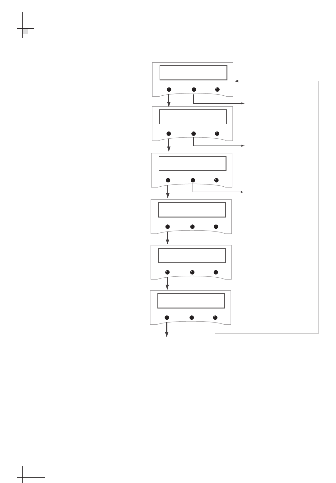
Figure 2-22
Install Satellite Screen
3. Follow the process shown in Figure 2-23 on the following
page to install your selected satellites. At the end of the
process, be sure to press the YES button to restart the
antenna.
Install Satellite?
Enter Next Return
Section 3, “Using the MCU
Interface,”
provides complete details
on the use of the MCU menus,
including complete antenna control
details in
“Control Antenna Mode”
on page 67.
• Galaxy3CN • Galaxy3CS
• Optus_B1 • Optus_B3
54-0198
44
TracVision G8 Owner’s Manual - Guide to Technical Information
Figure 2-23
Install Satellite Pair Process
Proceed to "Restarting
the Antenna"
Install Satellite?
Enter Next Return
Install A <SAT NAME>
Yes Next Cancel
Install B <SAT NAME>
Yes Next Cancel
Installing sats
Please wait
<SAT Name> and
<SAT NAME> installed
Selecting NEXT will cycle
the display through all
available satellites.
Selecting NEXT will cycle
the display through all
satellites that can be paired
with the selection for
Satellite A. If no satellite is
available for a pair or you
wish a single satellite
configuration, select NONE.
Refer to Tables 2-5 and
2-6 for available North
American and European
satellite pairs.
Restart antenna?
Yes No
Restart
Antenna
System
Installation
54-0198
45
Programming User-defined Satellites
The TracVision G8 satellite library has the capacity for two user-
defined satellites in case you want to track a satellite that is not
currently preprogrammed in the library. User-defined satellites
can only be configured via the MCU’s maintenance port. To
configure a user satellite, information about the satellite must be
provided, including:
• Satellite name
• Satellite position (longitude)
• Transponder information for each of the following
polarizations/frequencies:
- vertical high
- vertical low
- horizontal high
- horizontal low
OR
- right
- left
• Transponder information includes:
- frequency
- symbol rate
- FEC code
- network ID (in hexadecimal format)
This information can be obtained from your satellite service
provider or from a number of sites on the Internet, such as
www.satcodx.com.
How to tell the difference between
High and Low bands:
High: 11.700 - 12.750 GHz
Low: 10.700 - 11.700 GHz
For your reference, the satellite
configuration information for the
predefined satellites is available on
our web site at
www.kvh.com/
footprint
.
54-0198
46
TracVision G8 Owner’s Manual - Guide to Technical Information
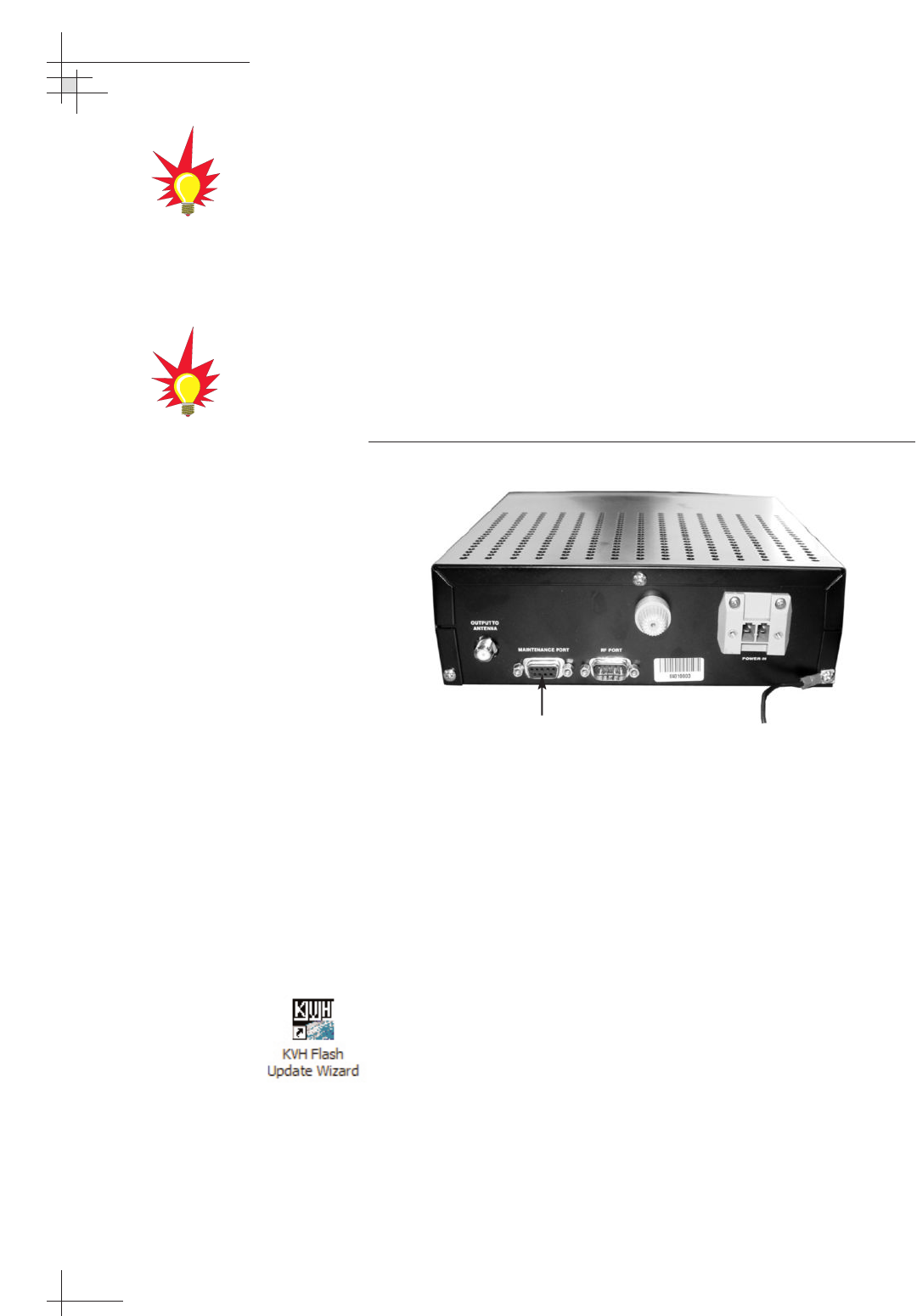
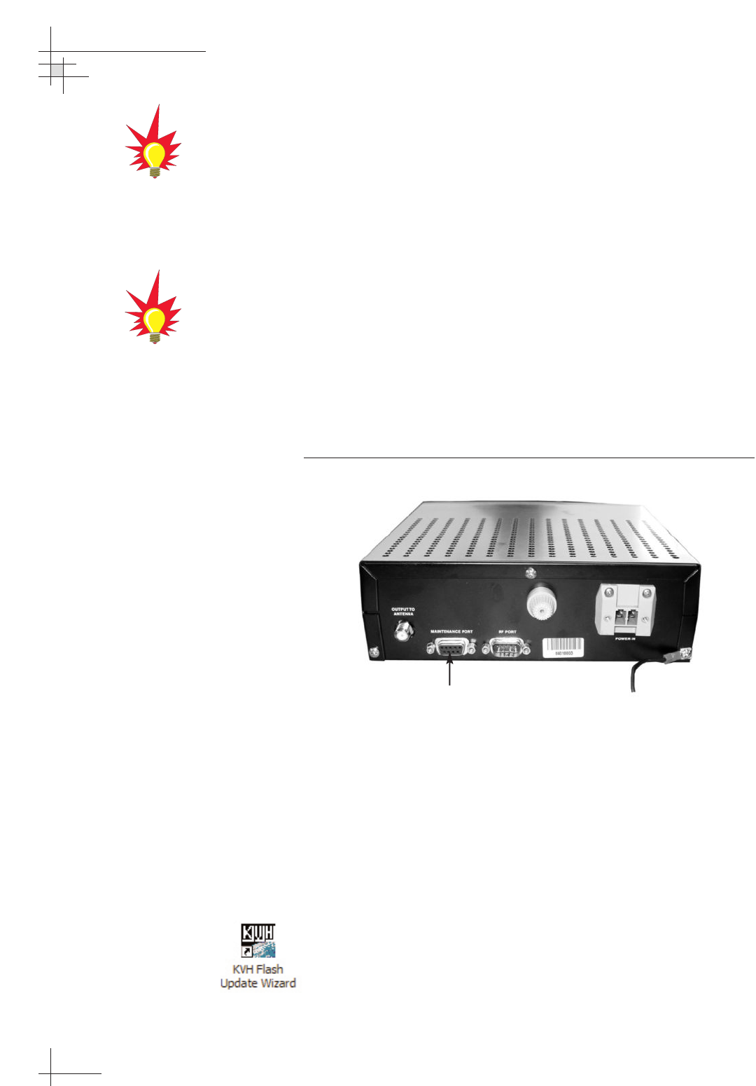
Connecting a PC to the MCU Maintenance Port
To program your user-defined satellites into the TracVision G8
satellite library, you need to connect a PC to the MCU’s
maintenance port. This procedure requires either the KVH Flash
Update Wizard or Windows HyperTerminal. Use the settings
appropriate to your application and follow the steps below.
1. Connect one end of the PC data cable to
the DB9 maintenance port connector on the rear of the
MCU. Connect the other end to the serial port on your PC
(a 9-pin/25-pin connector adapter may be needed for
some PCs).
Figure 2-24
MCU Maintenance Port
2. If you are using HyperTerminal, open HyperTerminal
and establish the following settings:
• Bits per second: 9600
• Data bits: 8
• Parity: None
• Stop bits: 1
• Flow control: None
If you are using the KVH Flash Update Wizard, double-
click the “KVH Flash Update Wizard” shortcut on your
computer’s desktop to start the wizard. Then go to the
“Select board to flash” screen.
3. Apply power to the TracVision G8 system and allow the
system to complete full initialization. Data should be
scrolling on the PC display to identify any system
problems detected. If no data appears, recheck your
connections and setup.
Maintenance Port
You can download the latest KVH
Flash Update Wizard at
www.kvh.com/wizard.
If your computer does not have a
DB9 serial COM port, you can use
the following USB-to-RS232
adapter:
IOGear part number GUC232A
(visit www.iogear.com)
Installation
54-0198
47
Entering User-defined Satellite Data
Enter the following antenna commands to configure your user-
defined satellites. If you’re using HyperTerminal, type the command
in the HyperTerminal window then press Enter. If you’re using the
KVH Flash Update Wizard, type the command in the “Command” box,
then press Enter.
1. Enter the SATCONFIG parser command as follows:
Command: SATCONFIG,USERX,YYY,Z,D,L<Enter>
(<Enter> indicates press the Enter key)
Where: X = 1 (USER1 satellite) or 2 (USER2 satellite)
YYY = longitude (0-180)
Z = E (East) or W (West)
D = decoding type (0 = test, 1 = DSS-A,
2 = DSS-B, 3 = DVB)
L = LNB polarization (C = circular, L = linear)
Function: configures one of the user-configurable satellites
with the longitude provided
Response: if valid entry, echoes the input data
if invalid entry, returns error message
2. Type @DEBUGON<Enter> to enter DEBUG mode.
3. Enter the satellite’s transponder information as follows:
Command: @SATCONFIG,X,N,F,S,C,ID,P,B,D<Enter>
Where: @SATCONFIG = directs data to the RF Board
X = satellite location (A = USER1, B = USER2)
N = satellite table # (98 = USER1, 99 = USER2)
F = frequency in MHz (either 00000 or within the
range 10700 - 12700)
S = the satellite transponder symbol rate in
Mbit/second (01000 - 29999)
C = the FEC code (e.g., 12, 23, 34, 56, 67, 78)
ID = the satellite network ID in hexidecimal format
(0x####)
P = the LNB polarization (v = vertical,
h = horizontal, r = right, l = left)
B = the LNB down conversion frequency (l = low,
h = high, G = Latin America, U = USA)
D = decoding type (1 = DSS-A, 2 = DSS-B,
3 = DVB)
54-0198
48
TracVision G8 Owner’s Manual - Guide to Technical Information
4. Repeat Step 3 for each of the following transponder
categories:
• vertical high • vertical low
• horizontal high • horizontal low
OR
• right • left
TracVision G8 requires that the data fields for all
transponder categories be provided. If the selected
satellite does not have information for one or more of the
transponder categories, default information should be
entered in the fields as follows:
Transponder Data Default Value
Frequency 00000
Symbol Rate 27500
FEC Code the same value as provided for those
transponders with data
Network ID 0x0000
Polarity and Band whichever combinations are not
already provided
5. Type ZAP<Enter> to restart the antenna.
6. If you need to configure a second user-defined satellite,
repeat this procedure starting with Step 1 to enter data for
the USER2 satellite.
You have now added your user-defined satellite(s) to the
system’s satellite library.
If you want the antenna to track one or both of these user-defined
satellites, you need to install it. To install a satellite, you can use
either the MCU, as described in “Installing Your Selected Satellites”
on page 43, or you can use the SATINSTALL command, as
described on the following page.
Installation
54-0198
49
1. Type HALT<Enter> to put the antenna in Idle mode.
2. Enter the SATINSTALL parser command as follows:
Command: SATINSTALL,<satA_name>,<satB_name><Enter>
Where: <satA_name> = the name of your choice for
Satellite A (for example: USER1)
<satB_name> = the name of your choice for
Satellite B (for example: USER2)
If you only want to install and track one satellite, enter
NONE as the name of Satellite B.
3. Once you’ve assigned satellites as Satellite A and Satellite
B, you need to tell the antenna which of the two satellites
it should initially acquire and track. This step should be
performed the first time a satellite is selected, allowing
the system to download the channel guide. To do so, enter
the following parser command:
Command: @L,A or B<Enter>
Where: A = track Satellite A
B = track Satellite B
4. Type ZAP<Enter> to restart the antenna.
Examples of the user-defined satellite configuration process are
provided for reference in the next two sections.
European systems only:
If DiSEqC is active on your
receiver, once the antenna restarts,
the antenna starts tracking the
satellite currently selected by the
receiver, overriding the @L
command.
54-0198
50
TracVision G8 Owner’s Manual - Guide to Technical Information
An Example of Configuring a User-defined Satellite (N. America)
The following is an example of configuring the fictional
YOURSAT 123 as the USER1 configured satellite. Prior to
configuring this satellite or any others, be certain to get the most
up-to-date information from one of the sources previously
discussed.
YOURSAT 123 at 122 West, DVB Decoder, Circular Polarization LNB
Right
Frequency 12.225 GHz
Symbol Rate 20000
FEC Code 5/6
Network ID 4100(dec) = 0x1004
Left
Frequency 12.456 GHz
Symbol Rate 20000
FEC Code 5/6
Network ID 4100(dec) = 0x1004
Based on this information, the data entered via the PC would
look like this:
SATCONFIG,USER1,122,W,3,C
@DEBUGON
@SATCONFIG,A,98,12225,20000,56,0x1004,R,U,3
@SATCONFIG,A,98,12456,20000,56,0x1004,L,U,3
@SAVE,A
ZAP
To install and start tracking the USER1 satellite, the following
additional data would be entered:
HALT
SATINSTALL USER1,NONE
@L,A
ZAP

Installation
54-0198
51
An Example of Configuring a User-defined Satellite (Europe)
The following is an example of configuring the fictional
YOURSAT 123 as the USER1 configured satellite. Prior to
configuring this satellite or any others, be certain to get the most
up-to-date information from one of the sources previously
discussed.
Yoursat 123 at 7 West, DVB Decoder, Linear Polarization LNB
Horizontal High
Frequency 11.966 GHz
Symbol Rate 27500
FEC Code 3/4
Network ID 2048 (dec) = 0x0800
Vertical High
Frequency 11.823 GHz
Symbol Rate 27500
FEC Code 3/4
Network ID 2048(dec) = 0x0800
Vertical Low
No Data Listed
Horizontal Low
No Data Listed
Based on this information, the data entered via the PC would
look like this:
SATCONFIG,USER1,7,W,3,L
@DEBUGON
@SATCONFIG,A,98,11966,27500,34,0x0800,H,H,3
@SATCONFIG,A,98,11823,27500,34,0x0800,V,H,3
@SATCONFIG,A,98,00000,27500,34,0x0000,V,L,3
@SATCONFIG,A,98,00000,27500,34,0x0000,H,L,3
@SAVE,A
ZAP
To install and start tracking the USER1 satellite, the following
additional data would be entered:
HALT
SATINSTALL USER1,NONE
@L,A
ZAP
54-0198
52
TracVision G8 Owner’s Manual - Guide to Technical Information
2.8 Checking Out the System
Now that you’ve installed the TracVision G8, you need to verify
that the system functions properly. Check the system startup
sequence to ensure that the system is operating within normal
parameters.
To view the startup sequence, connect a PC to the MCU’s
maintenance port. This procedure requires either the KVH Flash
Update Wizard or Windows HyperTerminal. Use the settings
appropriate to your application.
1. Connect one end of the PC data cable to the DB9
maintenance port connector on the rear of the MCU.
Connect the other end to the serial port on the PC
(a 9-pin/25-pin connector adapter may be needed for
some PCs).
Figure 2-25
MCU Maintenance Port
2. If you are using HyperTerminal, open HyperTerminal
and establish the following settings:
• Bits per second: 9600
• Data bits: 8
• Parity: None
• Stop bits: 1
• Flow control: None
If you are using the KVH Flash Update Wizard, double-
click the “KVH Flash Update Wizard” shortcut on your
computer’s desktop to start the wizard. Then go to the
“Select board to flash” screen.
Maintenance Port
You can download the latest KVH
Flash Update Wizard at
www.kvh.com/wizard.
If your computer does not have a
DB9 serial COM port, you can use
the following USB-to-RS232
adapter:
IOGear part number GUC232A
(visit www.iogear.com)
Installation
54-0198
53
3. Apply power to the TracVision G8 system and allow the
system to complete full initialization. Data should be
scrolling on the PC display to identify any system
problems detected. If no data appears, recheck your
connections and setup.
4. After completing the review of the startup and operational
routines, turn on the receiver and television and check the
channels on the selected satellites. For linear quad LNB
systems, check both horizontally and vertically polarized
channels, if possible.
5. When all checks are completed, shut down the system.
Checking the Calibration Score
Once the vessel is moving, the TracVision G8’s internal sensor
calibrates itself automatically to compensate for minor magnetic
distortions. Since a well-calibrated sensor is important to
maintain system performance, the “calibration score” should be
checked the first time the vessel is underway. See “Viewing the
Calibration Score” on page 79 for details.
A sample startup sequence has
been provided in
Appendix C on
page 127
with the typical ranges
and responses for the
TracVision G8 during startup and
operation.
Be sure to register the system for
product warranty validation. When
you register, you’ll also be added to
our customer contact list, which will
be used only to notify you of any
product updates. Please refer to the
Product Registration Form or visit
www.kvh.com/register.
54-0198
54
TracVision G8 Owner’s Manual - Guide to Technical Information
2.9 Changing Geographic Location
If you move to a different geographic area, you will need to
modify your TracVision G8 system to receive satellite TV signals
in the new location. To begin receiving satellite signals in the new
area, perform the following steps.
Swap LNB/Feed Tube Assembly
To receive the proper satellite signals in the new geographic
location, your TracVision antenna must be equipped with the
appropriate LNB/feed tube assembly for that location:
Table 2-6
Required LNB or LNB/Feed Tube Assembly for New
Geographic Location
Moving from: Moving to: Order from KVH:
North America Latin America DLA circular dual LNB
North America Europe Linear quad LNB/feed tube
Latin America Mexico
Australia
Latin America North America Standard circular dual LNB
Europe North America Standard circular dual
Mexico LNB/feed tube
Australia
Europe Latin America DLA circular dual
Mexico LNB/feed tube
Australia
Table 2-7 lists the part numbers for ordering these various
options.
Table 2-7
LNB and LNB/Feed Tube Assembly Part Numbers
Part Name Part Number
Standard circular dual LNB 02-0870
Standard circular dual LNB/feed tube assembly 02-1282-01
DLA circular dual LNB 02-0870-01
DLA circular dual LNB/feed tube assembly 02-1282-03
Linear quad LNB/feed tube assembly* 02-1282-04
* The linear quad LNB/feed tube assembly includes a skew control mechanism
that allows the antenna to automatically adjust skew for changes in region and
satellite service.
Installation
54-0198
55
Install New Satellites
When you move to a new area, the list of available satellites
changes. For details on available satellites by region and
installing these new satellites, refer to Section 2.7, “Installing
Satellites Using the MCU,” on page 42.
Replace the Receiver
In order to receive satellite TV service in your new geographic
location, you will need to purchase a receiver designed for that
location. You will also need to activate the receiver for a satellite
TV service that is available in that region. Refer to your selected
satellite TV service provider for more information.
You may also need to replace your
television when changing
geographic location. In North
America, your TV must support the
NTSC video standard. In Europe,
your TV must support the PAL
video standard.

Using the MCU Interface
54-0198
57
3 – Using the MCU
Interface
This section explains how to use all of the MCU functions. You will use
the MCU to operate, control, and monitor the TracVision G8.
Contents
3.1 Startup and Self-test . . . . . . . . . . . . . . . . . . . . . . . . . . . . . . . . . . .59
3.2 Main Display and Accessing the Main Menu . . . . . . . . . . . . . . . . .60
3.3 Installing Satellites . . . . . . . . . . . . . . . . . . . . . . . . . . . . . . . . . . . .62
3.4 Restarting the Antenna . . . . . . . . . . . . . . . . . . . . . . . . . . . . . . . . .64
3.5 Operations Mode . . . . . . . . . . . . . . . . . . . . . . . . . . . . . . . . . . . . . .64
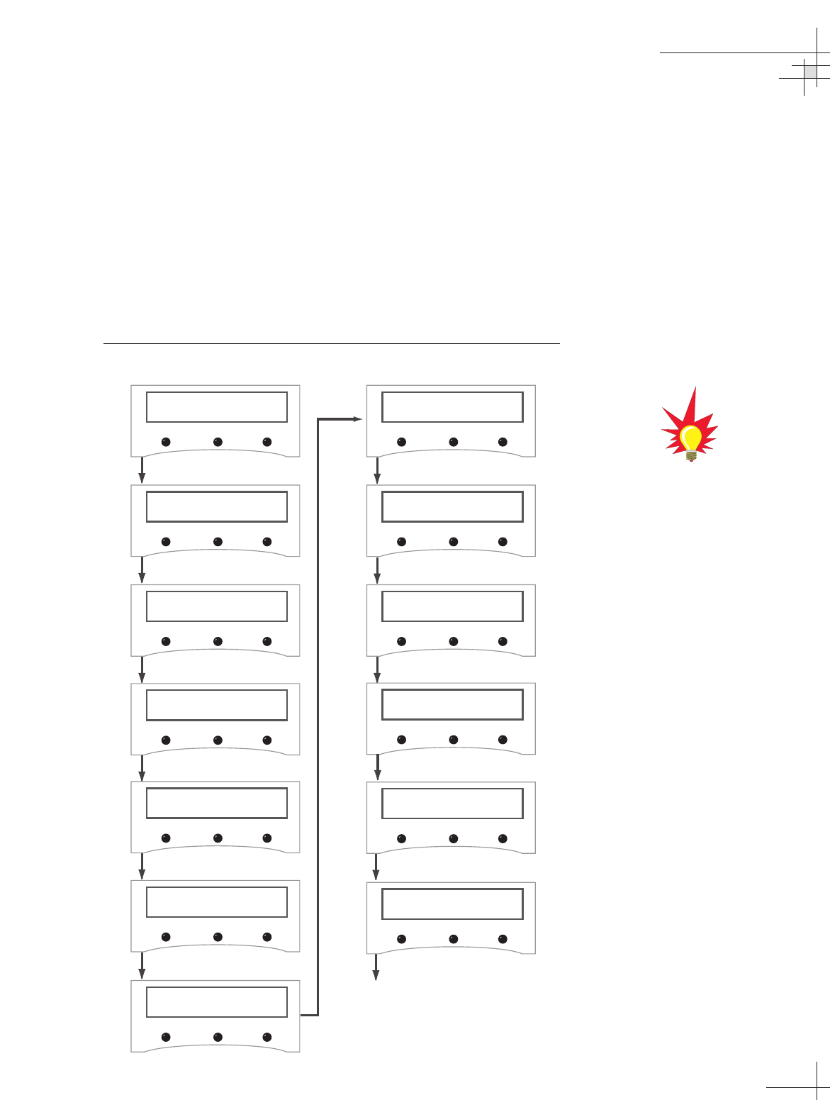
Using the MCU Interface
54-0198
59
3.1 Startup and Self-test
To turn on the TracVision G8, follow the steps below.
1. Turn on the satellite TV receiver and the television.
2. Apply operating power to the MCU.
3. Wait while the system initializes and searches for the
satellite.
The MCU displays the following screens during system startup:
Figure 3-1
TracVision G8 Startup Screens
KVH Industries, Inc.
TracVision G8
Init RF Board
Sat A Menu Sat B
Init Sensor
Sat A Menu Sat B
Init Antenna
Sat A Menu Sat B
Search mode 1
Sat A Menu Sat B
Search mode 2
Sat A Menu Sat B
Search mode 3
Sat A Menu Sat B
Network ID Check
Sat A Menu Sat B
Init Rate Bias
Sat A Menu Sat B
To Main Display
Tracking <SAT NAME>
Sat A Menu Sat B
Entering Tracking
Sat A Menu Sat B
Antenna initializing
Sat A Menu Sat B
Limit Switch Test
Sat A Menu Sat B
“Search Mode” screens may not
appear during every startup.
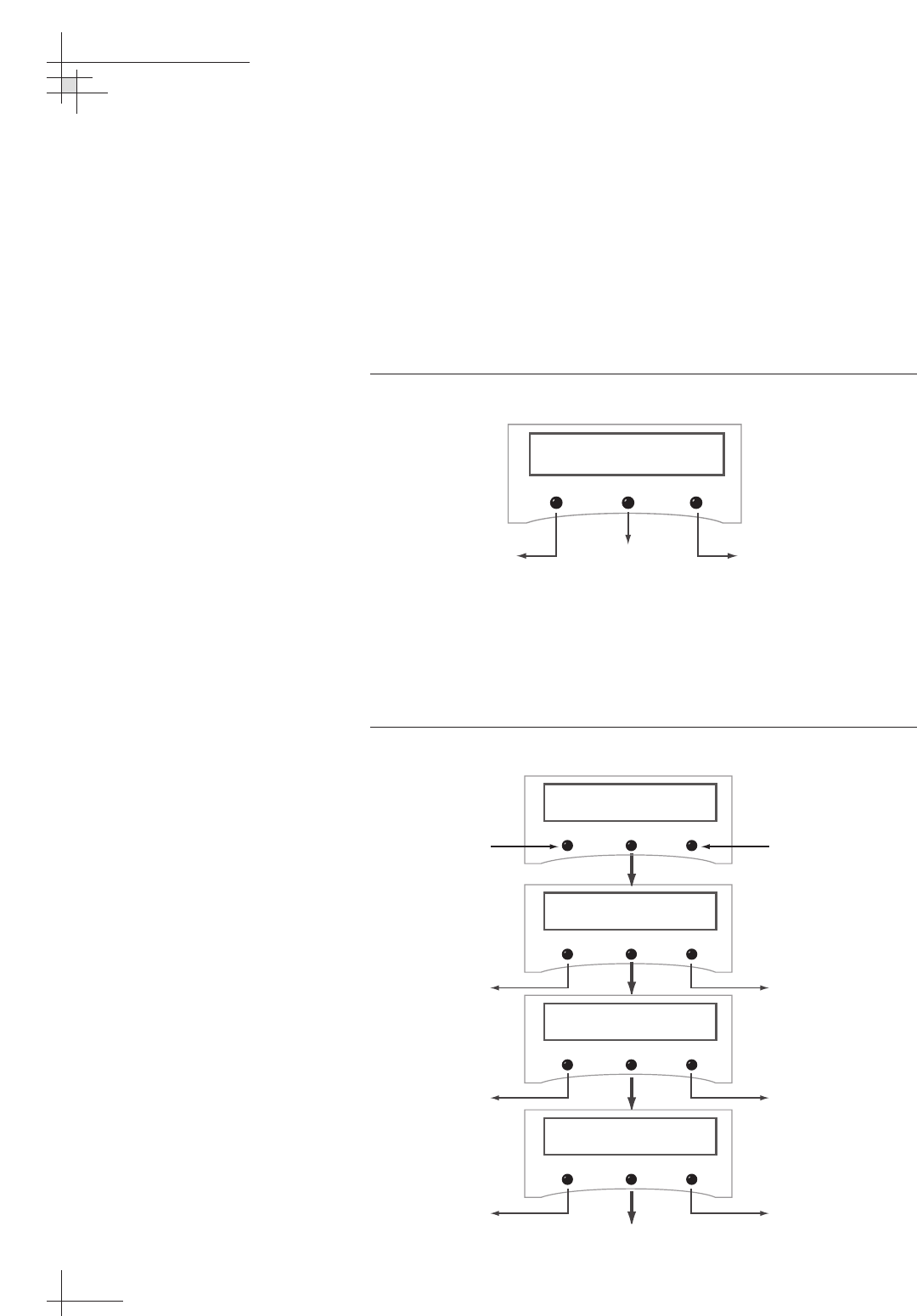
3.2 Main Display and Accessing
the Main Menu
As soon as the startup routine is completed, the LCD panel shows
the main display, which shows which satellite the antenna is
currently tracking. The buttons allow you to switch between the
two installed satellites as well as enter the main menu. The button
functions are as follows:
Figure 3-2
Main Display and Button Functions
Main Menu
Pressing the center button will cycle the main menu through the
available functions as follows:
Figure 3-3
Main Menu Functions
54-0198
60
TracVision G8 Owner’s Manual - Guide to Technical Information
Tracking <SAT NAME>
Sat A Menu Sat B
Track Installed
Satellite A
Track Installed
Satellite B
Enter
Main Menu
Install Satellite?
Yes Next Return
Tracking <SAT NAME>
Sat A Menu Sat B
Proceed to Section 3.3,
"Installing Satellites"
Restart Antenna?
Yes Next Return
Operations Mode?
Yes Next Return
Select Installed Satellite A Select Installed Satellite B
Proceed to Section 3.4,
"Restarting the Antenna"
Proceed to Section 3.5,
"Operations Mode"
Return to Main Display
Return to Main Display
Return to Main Display
Return to "Install
Satellite"
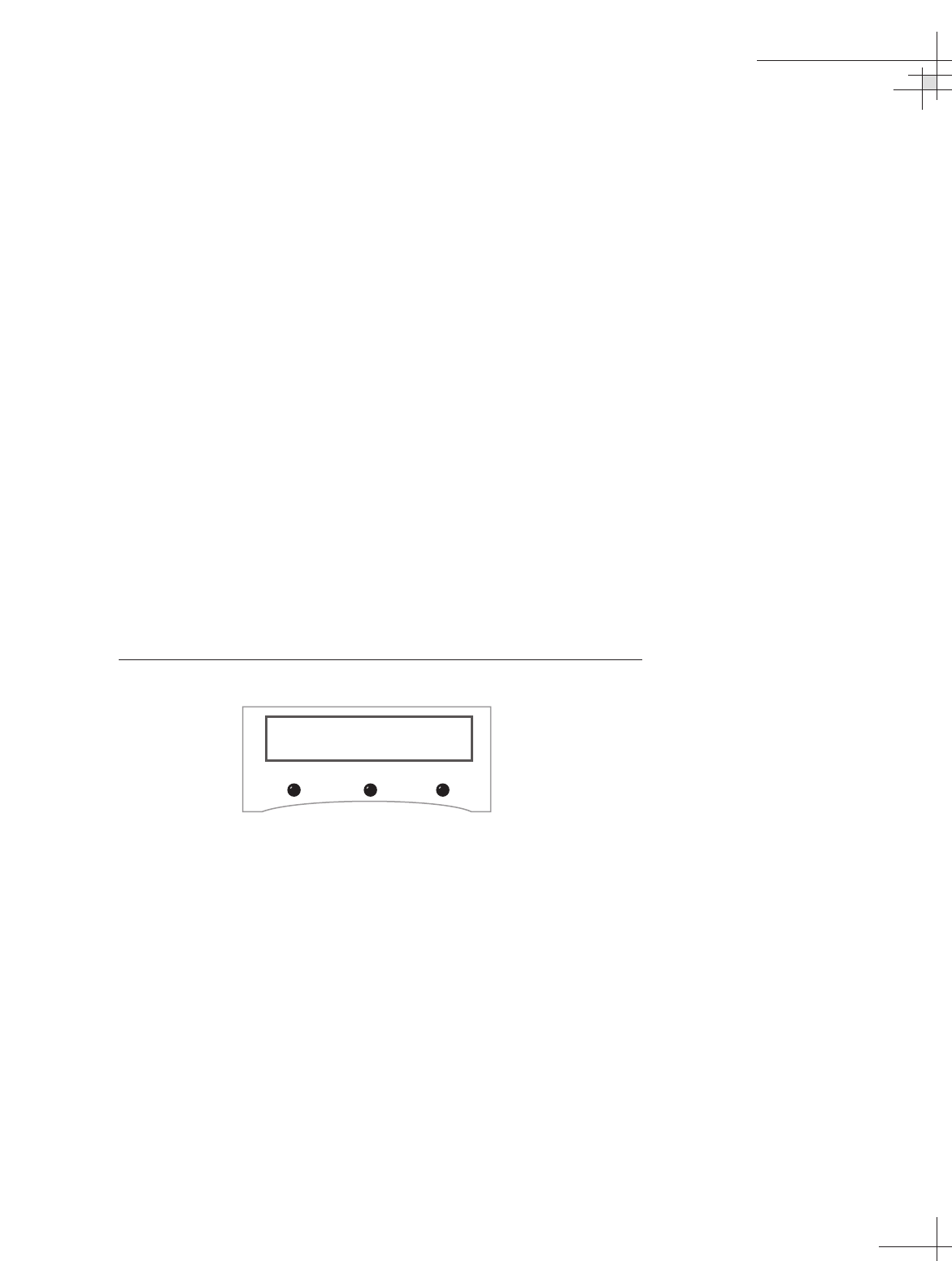
The RETURN and CANCEL Buttons
Throughout the menus, the right-hand button will often be
designated as either RETURN or CANCEL. These options have
the following functions:
•RETURN – Returns to the main menu or display. If no
buttons are pressed within 10 seconds, the menu will
automatically default to the main display.
•CANCEL – Cancels the current action and returns to the
start of the action without making any changes.
Antenna Error Messages
At times, the MCU might display error messages alerting you to
a specific problem (e.g., you have selected an invalid satellite
pair).
“Antenna not responding” (shown in Figure 3-4) indicates that
no messages are being received from the antenna. This is usually
the result of the antenna not being powered up or the antenna
being disconnected from the MCU. This error message might also
appear if the antenna hasn’t completed its limit switch test.
Figure 3-4
Non-responsive Antenna Error Message
Using the MCU Interface
54-0198
61
ERROR: Antenna
not responding
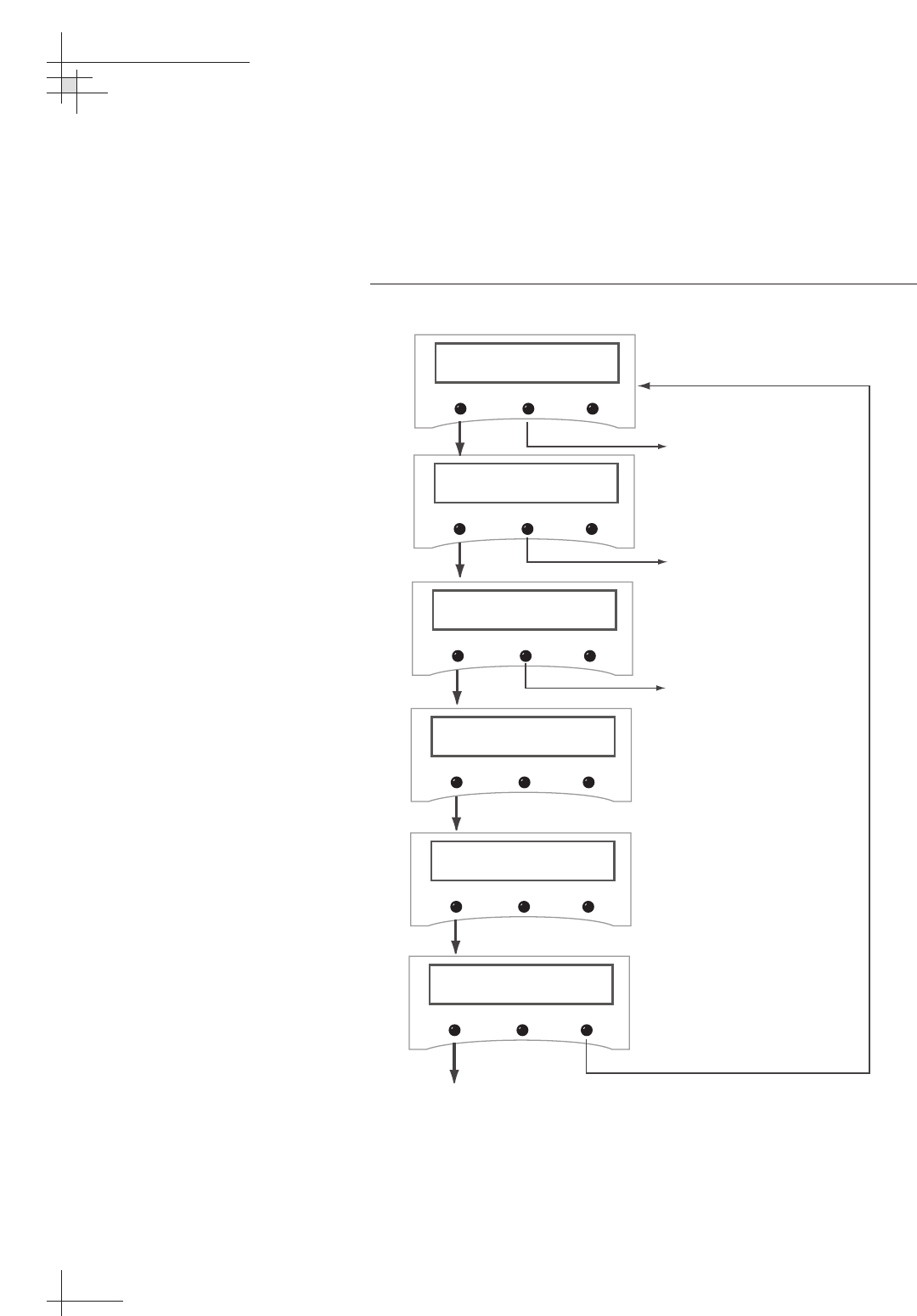
3.3 Installing Satellites
TracVision G8 permits two satellite services (Satellites A and B) to
be installed simultaneously. There is also an option for NONE on
Satellite B, permitting single satellite operation.
Figure 3-5
Install Satellite Pair Process
54-0198
62
TracVision G8 Owner’s Manual - Guide to Technical Information
Proceed to Section 3.4,
"Restarting the Antenna"
Install Satellite?
Yes Next Return
Install A <SAT NAME>
Yes Next Cancel
Install B <SAT NAME>
Yes Next Cancel
Installing sats
Please wait
<SAT Name> and
<SAT NAME> installed
Selecting NEXT will cycle
the display through all
available satellites.
Selecting NEXT will cycle
the display through all
satellites that can be paired
with the selection for
Satellite A. If no satellite is
available for a pair or you
wish a single satellite
configuration, select NONE.
Restart antenna?
Yes No
Restart
Antenna
System

Available Satellite Pairs
North America
Any two of the North American satellites listed below can be
paired together, as long as the satellites are within range of the
antenna (standard circular dual LNB required):
Europe
Any two of the European satellites listed below can be paired
together, as long as the satellites are within range of the antenna
(linear quad LNB/feed tube assembly required):
Mexico
In Mexico, select the satellite listed below for Sky Mexico service
(linear quad LNB/feed tube assembly required).
• PAS_9
Latin America
In Latin America, choose one of the satellites listed below for
DIRECTV Latin America (DLA) service (DLA circular dual LNB
required).
Australia
In Australia, you can pair together the two satellites listed below
(Linear quad LNB/feed tube assembly required).
Using the MCU Interface
54-0198
63
• Astra1 • Sirius
• Astra2N • Thor
• Astra2S • Arabsat
• Hispasat • Nilesat
• HotbirdWB • Turksat
• Hotbird • Eutel_W3A
• DSS_72 • Echo_110
• DSS_101 • Echo_119
• DSS_110 • Echo_148
• DSS_119 • Expressvu
• Echo_61 • ExpressTV
• Galaxy3CN • Galaxy3CS
• Optus_B1 • Optus_B3
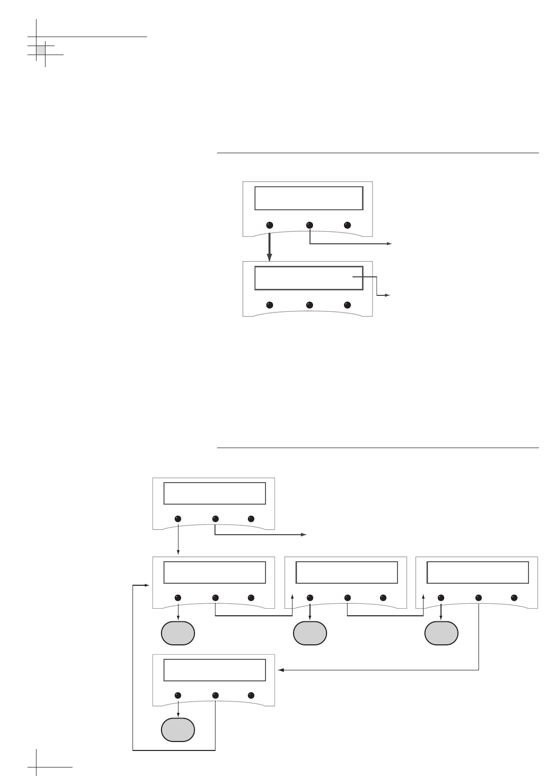
3.4 Restarting the Antenna
To restart the antenna, use the Restart Antenna menu. The
antenna will re-initialize and reacquire the satellite.
Figure 3-6
Restart Antenna Menu
3.5 Operations Mode
This sequence of menus allows a user to view system
information, perform various antenna functions, access internal
sensor functions, and set the display brightness.
Figure 3-7
Operational Mode Sequence
64
TracVision G8 Owner’s Manual - Guide to Technical Information
Restart antenna?
Yes Next Return
Antenna Restarted
Proceed to Section 3.5,
"Operations Mode"
This screen is displayed for 3 seconds
before returning to startup sequence
and main display
Get Antenna Status?
Yes Next Return
Control Antenna?
Yes Next Return
Operations Mode?
Yes Next Return
Control COMPASS?
Yes Next Return
Return to Section 3.3,
"Installing Satellites"
Set Brightness?
Yes Next Return
A B C
D
54-0198
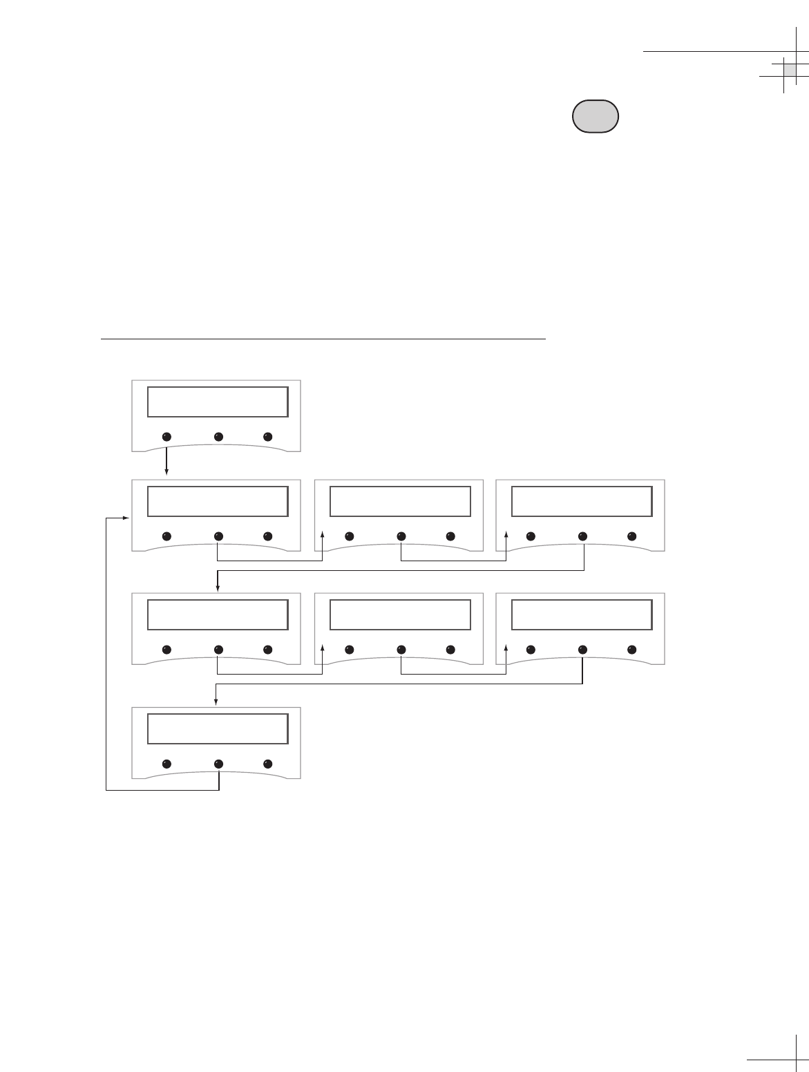
Antenna Status Mode
This sequence of menus allows a user to do the following:
Figure 3-8
Antenna Status Mode Menu Sequence
Figure 3-9 on the next page details each of these functions.
Using the MCU Interface
54-0198
65
Get Antenna status?
Yes Next Return
Get system errors?
Yes Next Return
Get version?
Yes Next Return
Get serial number?
Yes Next Return
Get thres/sig level?
Yes Next Return
Get skew angle?
Yes Next Return
Get bit error rate?
Yes Next Return
Get State?
Yes Next Return
A
• Scan for system errors
• Access antenna type,
version, and serial
number information
• Check signal/noise levels
• View the skew angle
• Display the bit error rate
• Display the antenna’s
current state
Antenna Status Data Screens
Figure 3-9 shows the information available through the Get
Antenna Status mode. This information is valuable for basic
troubleshooting and diagnostics.
Figure 3-9
Antenna Status Data Screens
54-0198
66
TracVision G8 Owner’s Manual - Guide to Technical Information
Get bit error rate?
Yes Next Return
Bit error rate
#####
Push any Button to Proceed
Get thres/sig level?
Yes Next Return
Proceed to "Control Antenna Mode"
Get Antenna status?
Yes Next Return
Get system errors?
Yes Next Return
Get Version?
Yes Next Return
MCU Antenna RF
#.## #.## #.#
Get skew angle?
Yes Next Return
Skew angle
##.#
(If errors detected)
Signal level = ####
Threshold = ####
OR
No errors detected
Testing OK
Test <Test Type>
Testing Failure
Push any Button to Proceed
Push any Button to Proceed
Push any Button to Proceed
Get serial number?
Yes Next Return
Antenna serial #
########
Push any Button to Proceed
Push any Button to Proceed
Test Types
Azimuth Motor
Elevation Motor
Skew Motor
Antenna Gyro
Internal Sensor
RF Comms
RF Signal
RF Config
Antenna Not
Responding
Get state?
Yes Next Return
State
<Current State>
Push any Button to Proceed
Current State
Initializing
Searching
Tracking
Idle
Error
Control Antenna Mode
This sequence of menus allows a user to do the following:
Figure 3-10
Control Antenna Mode Menu Sequence
Figures 3-11 through 3-20 on the following pages detail each of these functions.
Using the MCU Interface
54-0198
67
Set sleep on/off?
Yes Next Return
Control antenna?
Yes Next Return
Man control antenna?
Yes Next Return
Restart antenna?
Yes Next Return
Set instant on/off?
Yes Next Return
Install satellite?
Yes Next Return
Set Lat/Long?
Yes Next Return
select satellite?
Yes Next Return
Sat frequency Scan?
Yes Next Return
Set skew?
Yes Next Return
Configure satellite?
Yes Next Return
B
• Adjust the antenna’s
azimuth and elevation
• Restart the antenna
• Turn Sleep mode on/off
• Turn Instant On Mode
on/off
• Install a new satellite pair
• Set latitude/longitude
• Select the active satellite
• Adjust the skew angle
• Update satellite frequency
data
• Change satellite
configuration settings
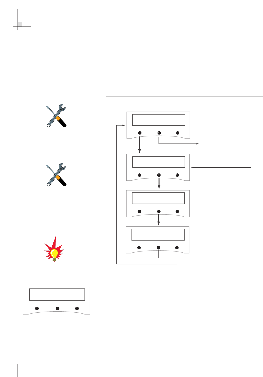
Manually Controlling the Antenna
In certain circumstances, you may need to control the azimuth,
elevation, and tracking of the TracVision G8 antenna manually,
using the process shown in Figure 3-11. Wait until the antenna
has fully initialized, then use the + and - buttons to manually
move the dish. Azimuth measurements are reported as relative to
the bearing of the vessel’s bow.
Figure 3-11
Manual Antenna Control Procedure
54-0198
68
TracVision G8 Owner’s Manual - Guide to Technical Information
Proceed to "Restarting the
Antenna"
Man control antenna?
Yes Next Return
AZ = XXX.X° EL = XX.X°
- Azimuth +
AZ = XXX.X° EL = XX.X°
- Elevation +
Make antenna track?
Yes No Cancel
YES tells the antenna to begin
actively tracking the set azimuth
and elevation. NO leaves the
antenna halted in its current
position.
If the manual adjustment of the
antenna reached the maximum
rotation (720°), the antenna will
rotate 360° and return to the
Manual Control Antenna screens.
InstantOn Reboot
Please wait
If the system started up in Instant
On mode, the following message
may be displayed:
Wait until the antenna has fully
initialized before making manual
adjustments.
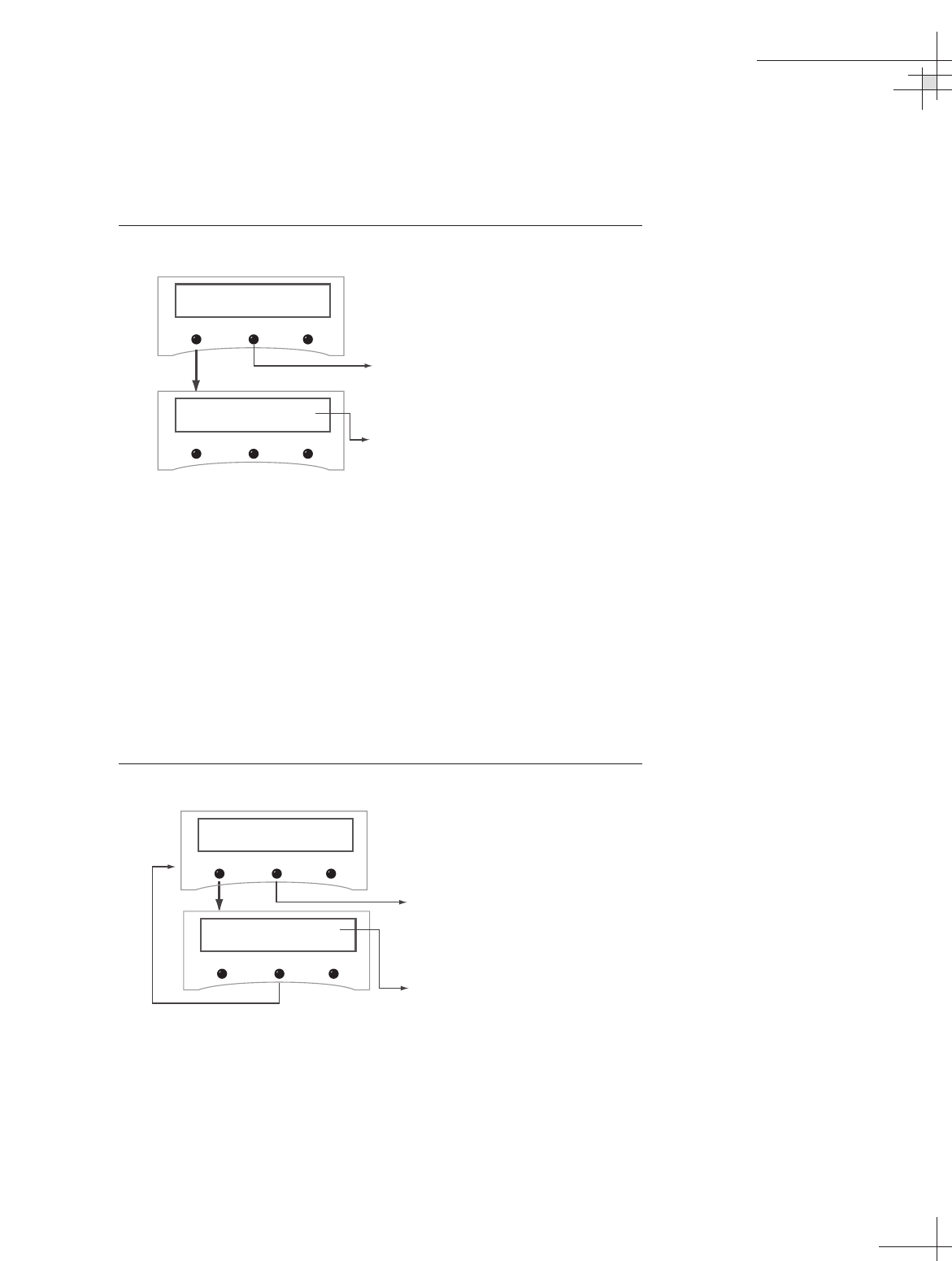
Restarting the Antenna
After resetting satellite parameters, it is necessary to restart the
antenna before the new settings take effect.
Figure 3-12
Restart Antenna Menu
Turning Sleep Mode On/Off
Sleep Mode, if activated, turns off conical scan tracking if the
antenna holds the same position for one minute. As soon as the
vessel moves, the system will automatically begin tracking the
satellite again.
The factory default setting for Sleep Mode is ON for North
American and Latin American systems and OFF for European
systems.
Figure 3-13
Sleep Mode Menu
Using the MCU Interface
54-0198
69
Restart antenna?
Yes Next Return
Antenna Restarted
Proceed to "Turning Sleep Mode
On/Off"
This screen is displayed for 3 seconds
before returning to startup sequence
and main data display
Set sleep On/Off?
Yes Next Return
sLEEP mode: ON
On Return Off The antenna communication setting will
be displayed based on current
selection. ON activates Sleep Mode.
Pushing the ON and OFF buttons will
change the selected setting.
Proceed to "Turning Instant On
Mode On/Off"
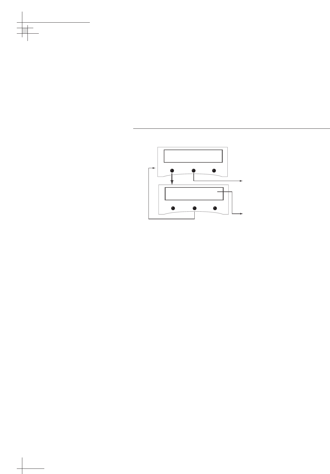
Turning Instant On Mode On/Off
Instant On allows the antenna to immediately receive a TV signal
if the vessel has not moved since the antenna was last shut off. If
the vessel moves after acquiring the satellite via Instant On, the
antenna will undergo its standard initialization process, resulting
in a brief interruption of the TV signal.
The factory default setting for Instant On Mode is OFF.
Figure 3-14
Instant On Mode Menu
54-0198
70
TracVision G8 Owner’s Manual - Guide to Technical Information
Set instant On/Off?
Yes Next Return
INSTANT mode: ON
On Return Off The antenna communication setting will
be displayed based on current selection.
ON activates Instant On Mode. Pushing
the ON and OFF buttons will change the
selected setting.
Proceed to "Installing a New
Satellite Pair"
Installing a New Satellite Pair
TracVision G8 permits two satellite services (Satellites A and B) to
be installed simultaneously. There is also an option for NONE on
Satellite B, permitting single satellite operation.
Figure 3-15
Install Satellite Pair Process
Using the MCU Interface
54-0198
71
Proceed to "Setting Latitude
and Longitude
Install Satellite?
Yes Next Return
Install A <SAT NAME>
Yes Next Cancel
Install B <SAT NAME>
Yes Next Cancel
Installing sats
Please wait
<SAT Name> and
<SAT NAME> installed
Selecting NEXT will cycle
the display through all
available satellites.
Selecting NEXT will cycle
the display through all
satellites that can be paired
with the selection for
Satellite A. If no satellite is
available for a pair or you
wish a single satellite
configuration, select NONE.
Refer to Tables 3-1 and
3-2 for available North
American and European
satellite pairs.
Restart antenna?
Yes No
Restart
Antenna
System
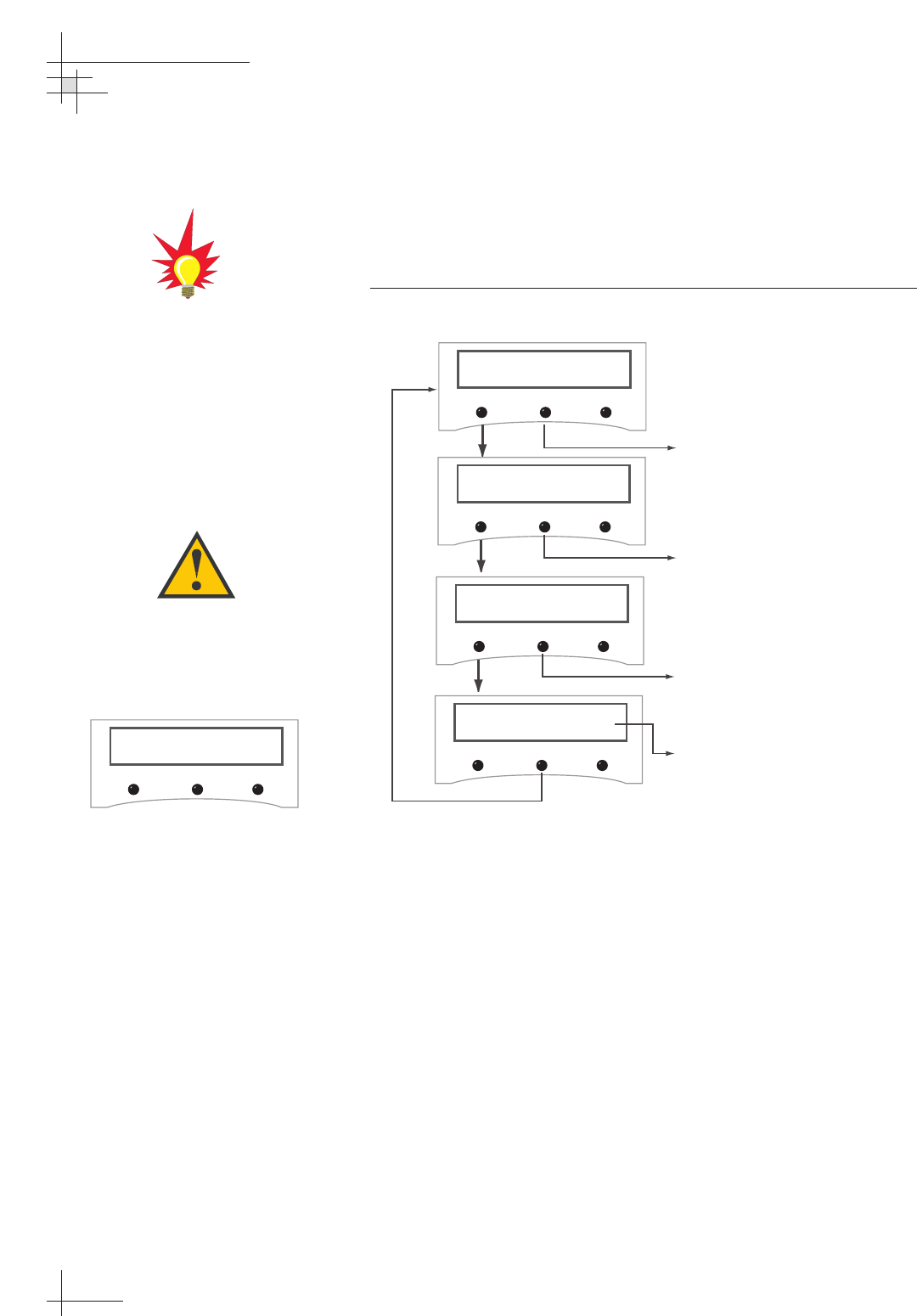
Setting Latitude and Longitude
If the GPS is blocked, faulty, or unavailable, you can enter the
vessel’s latitude and longitude to ensure that the installed
satellites are viewable, as well as to permit the system to set
several internal parameters.
Figure 3-16
Set Latitude/Longitude
54-0198
72
TracVision G8 Owner’s Manual - Guide to Technical Information
Proceed to "Selecting Active
Satellite"
Set Lat/Long?
Yes Next Return
Latitude: ##N
- Enter +
Longitude: ###E
- Enter +
Latitude: ##N
Longitude: ###E
Use the -/+ keys to select each
number and choose between NORTH
and SOUTH. Selecting ENTER will
cycle the display through each digit
and the direction option and then
launch the LONGITUDE screen.
Use the -/+ keys to select each number
and choose between EAST and WEST.
Selecting ENTER will cycle the display
through each digit and the direction
option and then display the selected
latitude and longitude.
This screen is displayed for
3 seconds before returning to
"Set Lat/Long?"
If the latitude and/or longitude
entered is not valid for the installed
satellite pair, the following screen
will appear:
Lat/Long not valid
for sat pair
Recheck and re-enter your latitude
and longitude and verify your
installed satellite pair to resolve this
issue.
If GPS is providing valid position
data to the antenna, manual entry
of latitude/longitude is not available.
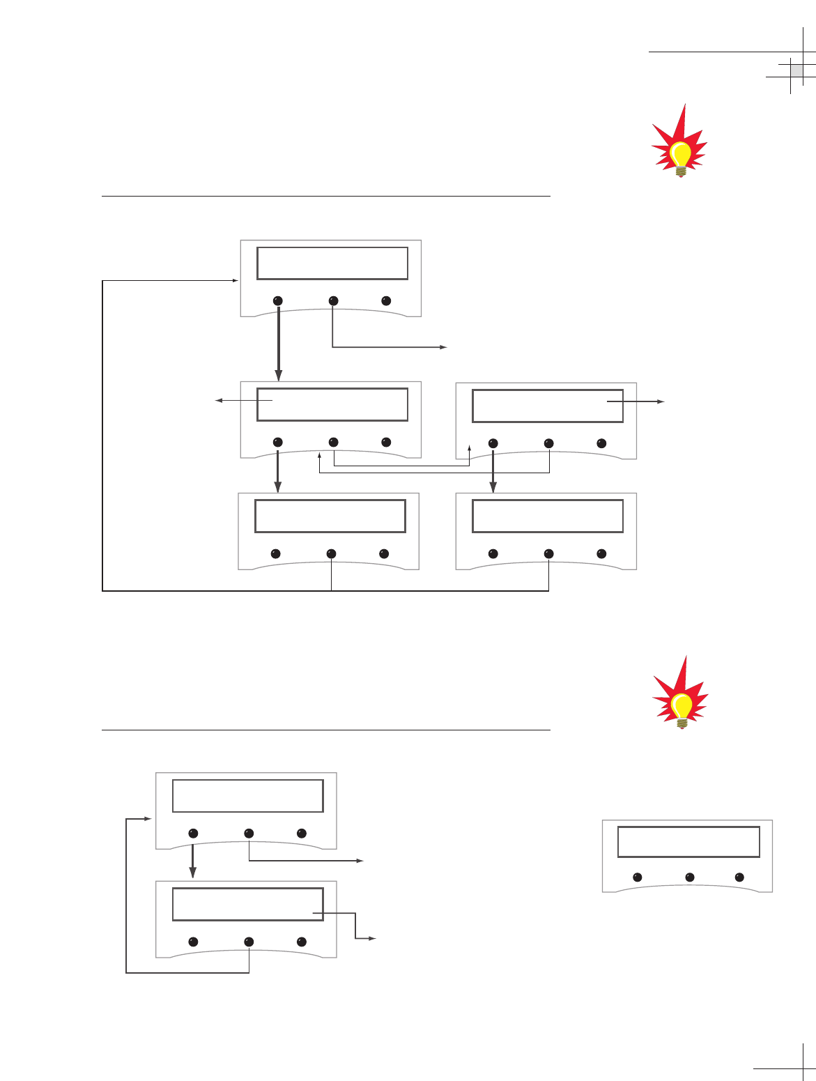
Selecting Active Satellite
After installing the active pair of satellites, use the Select Satellite
menu to choose which of the installed satellites will be active.
Figure 3-17
Select Active Satellite
Setting the Skew
The Set Skew menu allows you to manually adjust the skew of
the antenna’s LNB.
Figure 3-18
Set Skew Menu
Using the MCU Interface
54-0198
73
Proceed to "Setting the Skew"
Select Satellite?
Yes Next Return
Select <SAT NAME A>
Yes Next Cancel
Select <SAT NAME B>
Yes Next cancel
Sat Name A
corresponds to the
first satellite selected
during the Install
Satellite process.
Sat Name B
corresponds to the
second satellite
selected during the
Install Satellite
process.
<SAT NAME A> selected <SAT NAME B> selected
Proceed to "Updating Satellite
Frequency Data"
Set Skew?
Yes Next Return
Skew: +##.#
- Enter +
Enter the desired skew.
Use the -/+ keys to set the sign
("-" or "+") and each number.
Selecting ENTER will cycle the
display through each digit, then
return to "Set Skew."
European systems only:
If DiSEqC is active on your
receiver, once the antenna restarts,
the antenna starts tracking the
satellite currently selected by the
receiver, overriding the Select
Satellite command.
The skew can only be set on a
system equipped with a linear quad
LNB/feed tube assembly. Otherwise
the following screen will appear:
No skew adjustment
with installed sats
Updating Satellite Frequency Data
If the antenna is unable to find a satellite, the satellite’s frequency
data may have changed. The Satellite Frequency Scan feature
allows you to update the frequency data of any satellite stored in
the system’s library.
This function should not be used unless directed by KVH
Technical Support or a KVH-authorized technician.
With the desired satellite, band, and polarization selected, the
system will automatically search for the frequency with the
strongest signal. The system will then update that satellite’s
programmed data with the new frequency (and associated
network ID) and store it in the satellite library.
To update the satellite frequency data, follow the steps below:
1. Place your receiver in the satellite signal meter mode.
2. Select the desired satellite on the MCU. Ensure the TV
signal meter indicates that you have a strong signal.
If the antenna is unable to find the selected satellite
automatically, you can manually point the antenna (see
“Manually Controlling the Antenna” on page 68).
3. Select the desired polarization and band on the receiver.
4. Do not move the vessel. Your boat must remain
motionless during the entire Satellite Frequency Scan
process.
5. Follow the MCU menus on the next page. The scan itself
will take a couple of minutes. Once complete, restart the
antenna and ensure the antenna will track the new
frequency.
54-0198
74
TracVision G8 Owner’s Manual - Guide to Technical Information
Do NOT use this function unless
directed by KVH Technical Support
or a KVH-authorized technician.
Improper data selection may affect
the system’s operation.
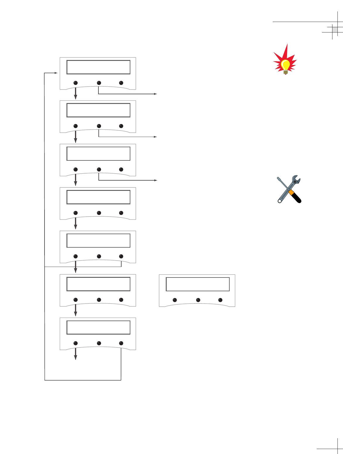
Figure 3-19
Satellite Frequency Scan
Using the MCU Interface
54-0198
75
Proceed to "Configuring Satellite
Settings"
Sat frequency Scan?
Yes Next Return
Sym Rate: XXXXXm/s
- Enter +
Set FEC code: X/X
- Enter +
Scan frequencies
Please Wait
Update frequency?
YES NO
Updating frequency
Please wait
Restart antenna?
YES NO
Use the -/+ keys to select each
number. Selecting ENTER will cycle
through each digit and then launch
the FEC code screen.
(Valid settings are 01000-39999.)
Use the -/+ keys to scroll through
the available FEC codes:
1/2 - 2/3 - 3/4 - 5/6 - 6/7 - 7/8.
Use the ENTER key to accept your
selection.
Restart
Antenna
System
No strong frequency
Exit
If no strong satellite signal is found
at the selected frequency, the
screen will display:
Exit returns you to the "Sat
Frequency Scan" screen.
Try the
process again, but using a different
symbol rate or FEC code.
This scan may take up to
10 minutes to complete.
The vessel must remain stationary
during this process.
To find a valid symbol rate and FEC
code, refer to an up-to-date satellite
information table. Data for satellites
stored in the antenna’s library is
available for download at
www.kvh.com/footprint. For other
satellites, you might refer to an
Internet resource such as
www.lyngsat.com or
www.satcodx.com (these sites are
not managed by KVH).
Configuring Satellite Settings
The Configure Satellite menu allows you to change the
configuration settings for your installed satellites. For each
polarization, you can change the following settings:
•Frequency
(either 00000 or a number between 10700 - 12700 MHz)
•Symbol Rate
(01000 - 45000 Mbit/sec)
•FEC Code
(1/2, 2/3, 3/4, 5/6, 6/7, or 7/8)
•Satellite Network ID
(0x0000 - 0xffff hex)
54-0198
76
TracVision G8 Owner’s Manual - Guide to Technical Information
North American satellites have two
polarizations:
• Left-hand Circular (LHC)
• Right-hand Circular (RHC)
European satellites have four
polarizations:
• Horizontal High (HH)
• Horizontal Low (HL)
• Vertical High (VH)
• Vertical Low (VL)
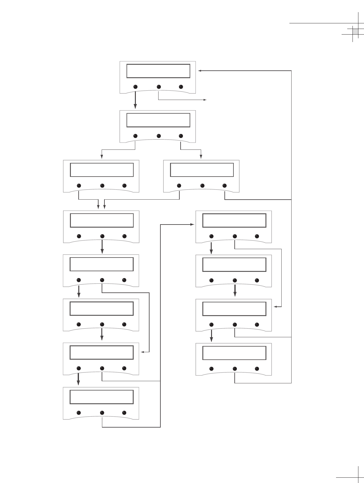
Figure 3-20
Configure Satellite
Using the MCU Interface
54-0198
77
Return to "Manually Controlling
the Antenna
Configure satellite?
Yes Next Return
Configure satellite
Sat A Sat B
Sym Rate: XXXXXM/S
- Enter +
Configure Symbol rate?
Yes Next Cancel
Set Freq: XXXXXMHz
- Enter +
Configure frequency?
Yes Next Cancel
Configure A <SAT NAME>?
Yes No
Configure B <SAT NAME>?
Yes No
Set ID: XXXXXXHEX
- Enter +
Configure FEC code?
Yes Next Cancel
Set FEC Code: X/X
- Enter +
Configure network ID?
Yes Next Cancel
Use the -/+ keys to set each digit of the number. Selecting
ENTER will cycle the display through each digit and then
display the next configuration screen.
Note 2:
Use the -/+ keys to scroll through the available FEC codes:
1/2 - 2/3 - 3/4 - 5/6 - 6/7 - 7/8.
Use the ENTER ke
y
to acce
p
t
y
our selection.
Note 3:
Note 2
Note 2
Note 3
Note 2
Polarization: XXX
- Enter +
Note 1
Use the -/+ keys to scroll through the available polarizations:
LHC - RHC - HH - HL - VH - VL.
Use the ENTER key to accept your selection.
Note 1:
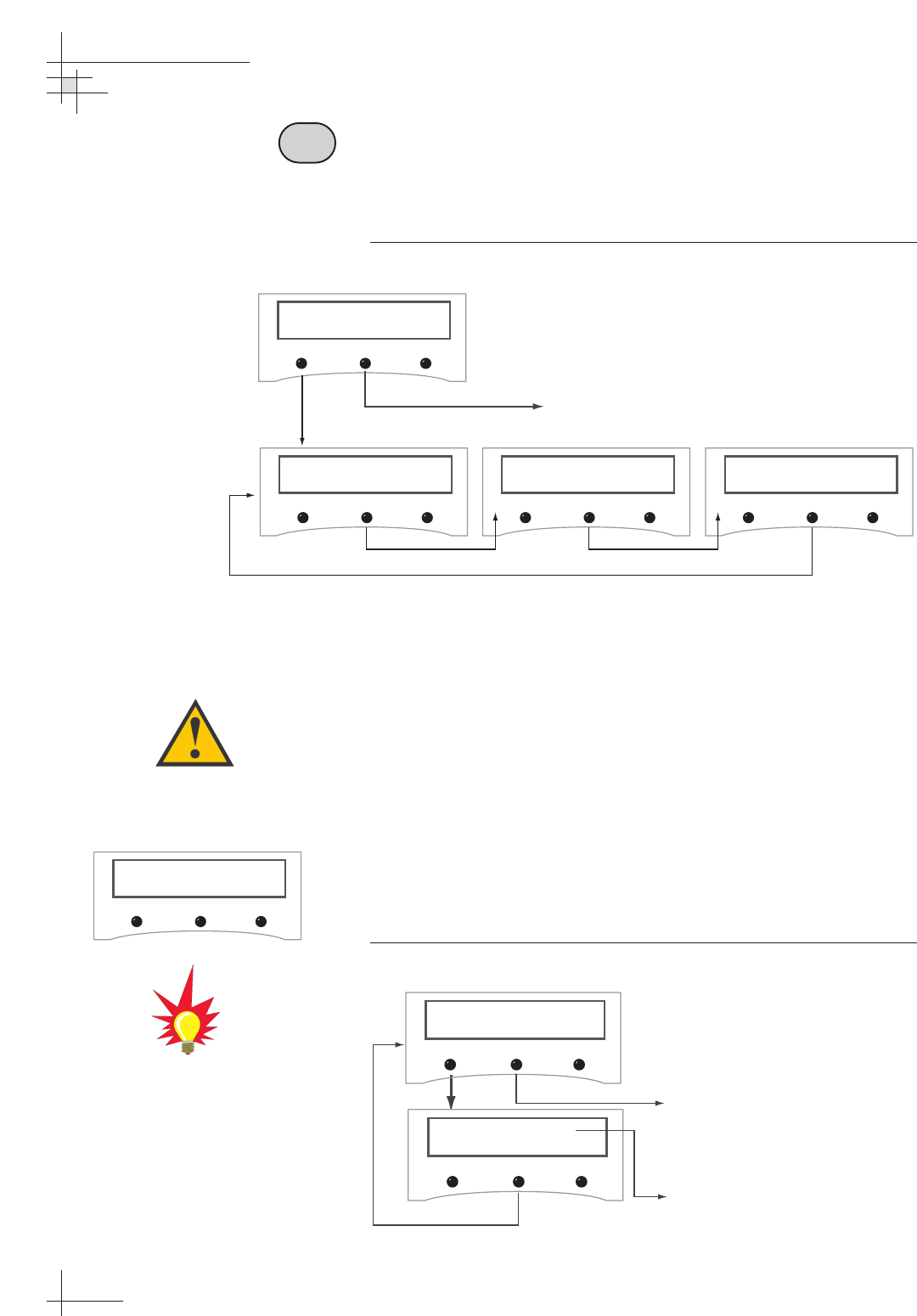
Control Compass Mode
The Control Compass function allows you to turn autocalibration
on/off, read the calibration score, and clear the calibration.
Figure 3-21
Control Compass Mode Menu Sequence
Selecting Autocalibration
Every antenna’s internal sensor module is calibrated at the
factory in a perfect-world environment. However, hard and soft
iron effects on your vessel can distort the local magnetic field,
causing errors in the reported heading. These errors are
minimized by mounting the antenna in a suitable location and
are further removed by the system’s autocalibration feature,
which compensates for minor magnetic distortions while your
vessel is moving. The more the vessel moves with autocalibration
turned on, the more accurate the sensor will become.
The factory default setting for Autocalibration is ON.
Figure 3-22
Setting Autocalibration
54-0198
78
TracVision G8 Owner’s Manual - Guide to Technical Information
Set autocal on/off?
Yes Next Return
Get cal score?
Yes Next Return
Control Compass?
Yes Next Return
Clear Cal Score?
Yes Next Return
Proceed to "Setting Display
Brightness"
Set autoCal On/Off?
Yes Next Return
AutoCal is: ON
ON Return OFF
Proceed to "Viewing the
Calibration Score"
Autocalibration setting will be displayed
based on current selection. Pushing
the ON or OFF buttons will change the
selected setting.
A well-calibrated sensor is crucial
to system performance. If you shift,
remove, or add equipment near the
antenna, KVH suggests keeping
autocalibration ON so that the
sensor will automatically recalibrate
itself.
If the antenna’s internal sensor is
not working, the following screen
will appear:
Operation not avail
No internal sensor
C
Viewing the Calibration Score
The calibration score should be checked the first time you are
underway after installing the TracVision G8 and whenever
adjustments are made to vessel equipment that can affect the
sensor’s accuracy.
Figure 3-23
Viewing Calibration Score
Figure 3-24
Sample Calibration Score Screen
Accuracy (ACC)
The ACC data indicates the sensor’s degree of accuracy. Table 3-2
lists the five possible accuracy levels.
Table 3-2
Possible Compass Accuracy Levels
ACC Score Accuracy
<1ºBetter than 1º
<2ºBetter than 2º
<4ºBetter than 4º
<8ºBetter than 8º
BAD CAL Poor cal
Using the MCU Interface
54-0198
79
ACC MagEnv Cal#
CAL<1° GOOD 3
Accuracy
Magnetic Environment
Calibration Update
Number
Proceed to "Clearing the
Calibration"
Get Cal Score?
Yes Next Return
ACC MagEnv Cal#
CAL<#° XXXX #
If the system has never been
calibrated in the field, the following
screen will appear:
Factory Cal OK
No Field Cal
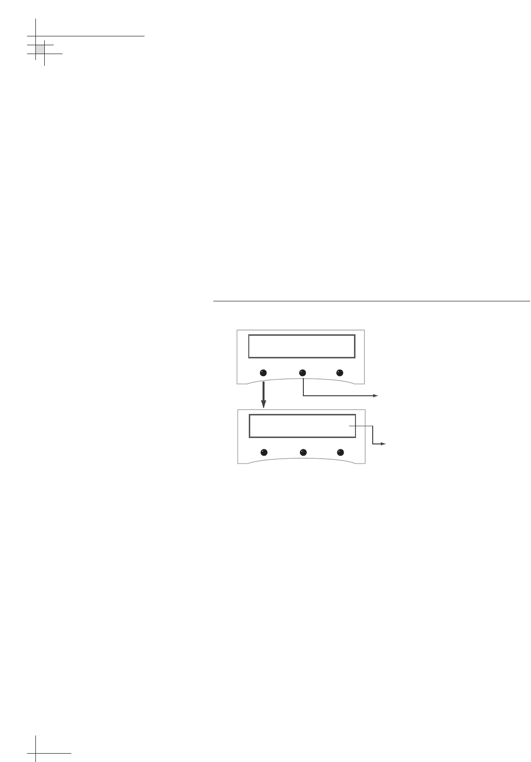
Magnetic Environment (MAGENV)
The MAGENV score (GOOD, OK, POOR, BAD) indicates the
quality of the installation location. If the quality is POOR or BAD,
the antenna may need to be moved to a more favorable magnetic
environment, or the source of magnetic interference needs to be
relocated.
Calibration Update Number (CAL #)
The CAL # indicates the number of times the sensor has
calibrated itself. It is used primarily to verify whether a new
calibration has been accepted by the system.
Clearing the Calibration
Clearing the calibration resets the system to the factory defaults.
Figure 3-25
Clearing the Calibration
54-0198
80
TracVision G8 Owner’s Manual - Guide to Technical Information
Return to "Selecting
Autocalibration"
Clear Cal Score?
Yes Next Return
Cal score Cleared
Press any button to return to
"Clear Cal Score?"
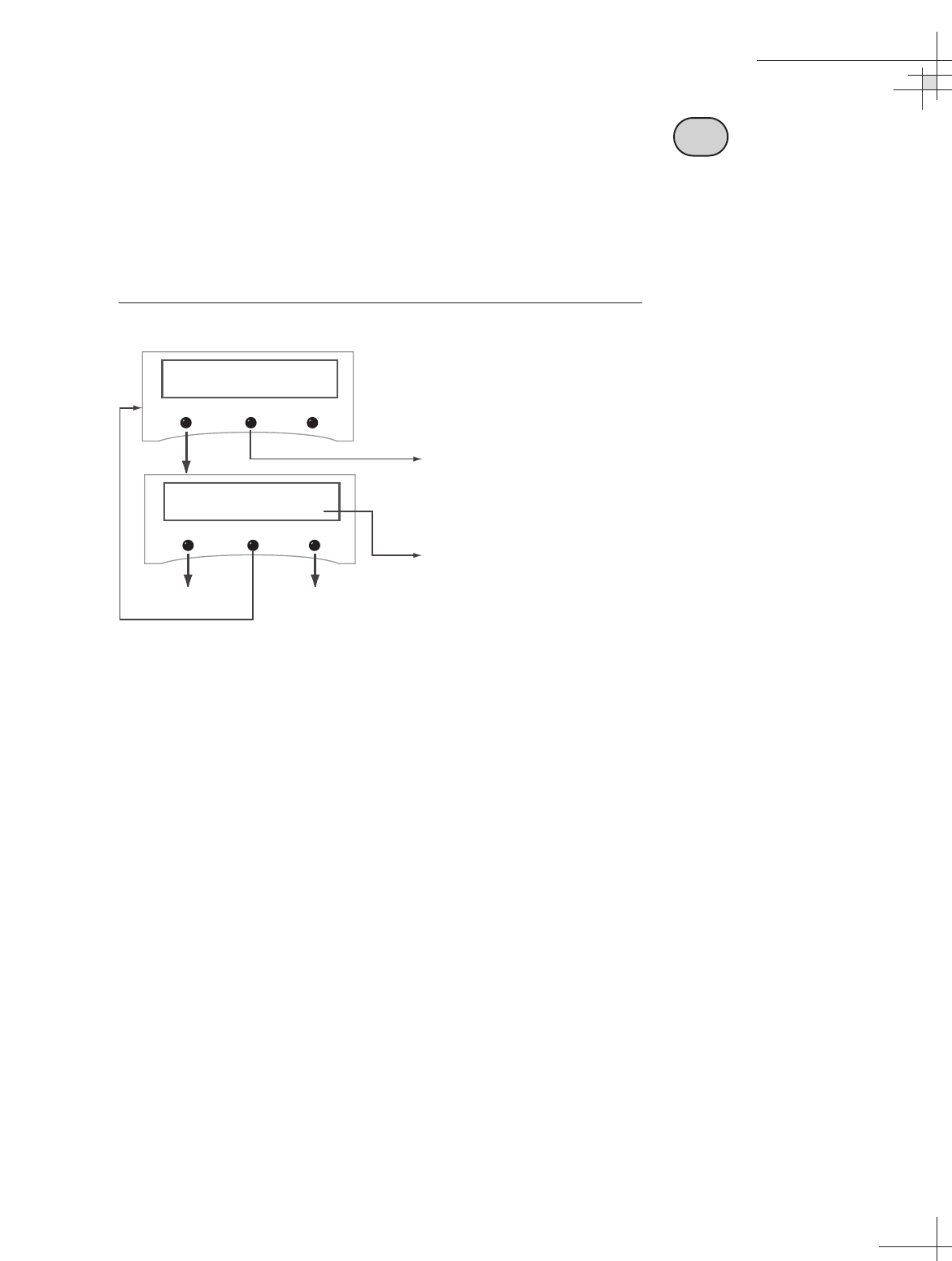
Setting Display Brightness
The MCU display’s brightness may be adjusted to suit your
preferences. Press the right-hand button to make the display
brighter; press the left-hand button to make it dimmer. When you
are satisfied with the setting, press the center button to accept the
setting.
Figure 3-26
Setting Display Brightness
Using the MCU Interface
54-0198
81
Return to "Antenna
Status Mode"
Set brightness?
Yes Next Return
Min Bright Max
*****************
Dim Display Brighten Display
The MCU display offers
20 levels of brightness,
indicated by the number of
asterisks.
Accept Setting
and Return
D

Troubleshooting
54-0198
83
4 – Troubleshooting
This section identifies basic trouble symptoms and lists their possible
causes and solutions.
Contents
4.1 Troubleshooting Matrix . . . . . . . . . . . . . . . . . . . . . . . . . . . . . . . . .85
4.2 Causes and Remedies for Common Operational Issues . . . . . . . .86
4.3 Receiver Troubleshooting . . . . . . . . . . . . . . . . . . . . . . . . . . . . . . .89
4.4 Antenna Gyro and LNB Faults . . . . . . . . . . . . . . . . . . . . . . . . . . . .89
4.5 Computer Diagnostics . . . . . . . . . . . . . . . . . . . . . . . . . . . . . . . . . .90
4.6 Maintenance Port Parser Commands . . . . . . . . . . . . . . . . . . . . . .91
Troubleshooting
54-0198
85
4.1 Troubleshooting Matrix
The troubleshooting matrix shown in Table 4-1 identifies some
trouble symptoms, their possible causes, and references to
troubleshooting solutions.
Table 4-1
Troubleshooting Matrix
Antenna non-functional 1 2
Antenna not switching satellites via remote 2 1 1 1 3 2 2 2 2
Antenna not switching satellites via MCU 2 1 1 1 3 2
No picture on TV set 1 1 2 2 2 2 2
Certain channels do not work 2 1 1 1 3 2 2 2
Intermittent picture for short intervals 1 1 1 2 2 2 3 2
System works at dock but not on the move 1 3
System will not find satellite 2 1 1 1 1 2 3 2 2 2 3 2
Snowy television picture 2 1 2 2
Pixelating television picture 2 1 2 2 2 3 2
Satellite coverage issue
Antenna gyro faulty (Section 4.4)
LNB assembly faulty (Section 4.4)
Satellite signal blocked
Incorrect or loose RF connectors
Radar interference
POSSIBLE CAUSE (AND SOLUTION)
SYMPTOM
Power disturbance, blown fuse, or low power
Vessel turning during startup
Type of multiswitch used
Incorrect satellite configuration
Receiver faulty/improperly configured (Section 4.3)
Satellite frequency data changed
Section 4.2
Key
1 = Anyone can do
2 = Electronics know-how recommended
3 = Dealer service recommended
Improper wiring
Data/power cable interference
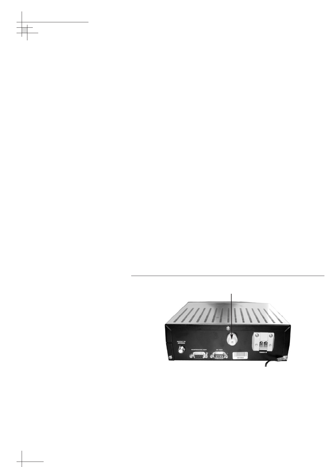
54-0198
86
TracVision G8 Owner’s Manual - Guide to Technical Information
4.2 Causes and Remedies for
Common Operational Issues
There are a number of common issues that can affect the
performance of the TracVision G8. The following sections address
these issues and potential solutions.
Power Disturbance, Blown Fuse, or Low Power
Power Disturbance
If the MCU detects a short in the output to the antenna,
the MCU’s resettable fuse trips. If this occurs, remove the
short then wait one minute for the fuse to reset. If the
MCU detects any other power disturbance, such as a
voltage spike, the system shuts itself down. If this occurs,
simply disconnect power from the MCU, wait 20 seconds,
then restore power.
Blown Fuse
The antenna unit is equipped with a 5-amp, 125-volt fast-
blow fuse on the PCB module. The MCU is equipped
with a 15-amp, 125-volt fast-blow fuse on its rear panel. If
either of these fuses has blown or been broken, the system
will not work. To access the MCU fuse, simply unscrew
the fuse holder cap on the rear panel. For details on
accessing the antenna’s PCB module fuse, refer to
Section 5.5, “Replacing the PCB Module Fuse,” on page 98.
Figure 4-1
MCU Fuse
Low Power
If the power cable from vessel power to the MCU is more
than 50 ft (15 m) in length, the power level can decrease
over the course of the cable, resulting in a voltage level at
the antenna unit that is too low to power the system.
Refer to “Connecting Vessel Power and the MCU Ground
Wire” on page 36 for details on supplying adequate power
to the antenna unit.
Fuse
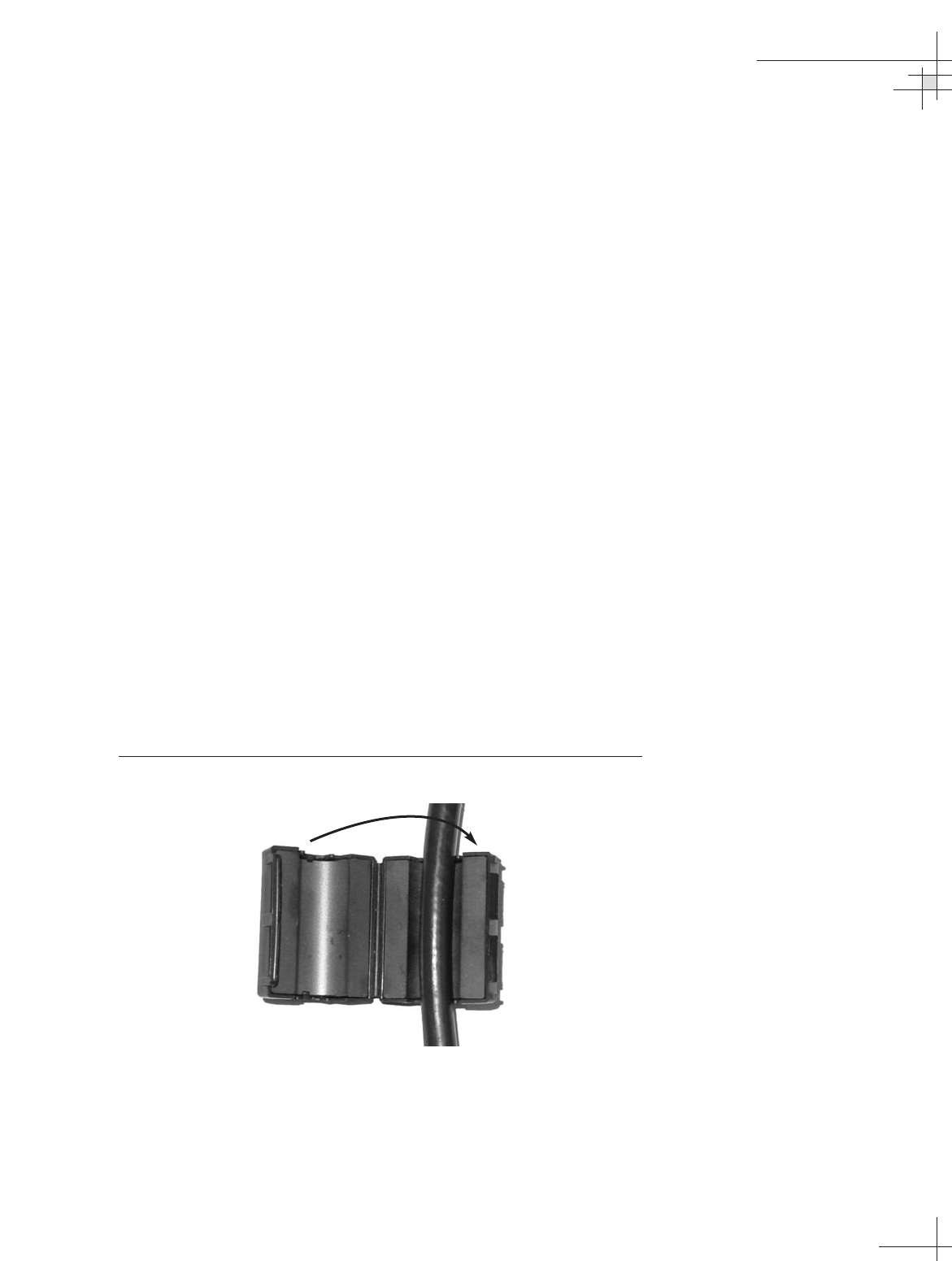
Improper Wiring
If the system has been improperly wired, the antenna unit will
not operate correctly. Refer to Section 2.4, “Wiring the MCU,” on
page 35 for complete system wiring information.
Vessel Turning During Startup
If the vessel turns during the two-minute startup sequence that
occurs immediately after turning on the power to the
TracVision G8, the antenna will record that variable motion as
“standing still.” This may cause the antenna to track
improperly. To solve this problem, turn the TracVision G8 off
for at least 10 seconds. Then turn the system back on, ensuring
that the vessel is either motionless or traveling in a straight line
for the two minutes immediately following power-up.
Data/Power Cable Interference
Depending on how cables are routed, conducted emissions from
the system’s data/power cable may cause reduced picture
quality on your TV screen. If the picture quality degrades only
when the TracVision G8 is operating, try installing the small
ferrite coil supplied in the kitpack. Simply clamp it onto the
data/power cable to reduce its conducted emissions (see
Figure 4-2). You might also try grounding the receiver to a
suitable earth ground.
Figure 4-2
Small Ferrite Coil
Troubleshooting
54-0198
87
Incorrect Satellite Configuration
(European Systems Only)
The satellite configuration on European receivers must match the
satellite settings on the TracVision G8 system.
• Satellite A on the TracVision G8 must be the same satellite
as receiver Alternative 1 (or A, based on your receiver)
and must be assigned the receiver DiSEqC 1 setting.
• Satellite B on the TracVision G8 must be the same satellite
as receiver Alternative 2 (or B, based on your receiver)
and must be assigned the receiver DiSEqC 2 setting.
Refer to your receiver’s user manual for complete instructions on
configuring your receiver.
Satellite Signal Blocked
Satellite signals can be blocked or degraded by buildings, other
vessels, or equipment on the vessel itself. Refer to “Choosing the
Best Location for the TracVision Antenna” on page 23 to make certain
that the TracVision G8 antenna unit is in the optimal location.
Simply moving the vessel to clear an external obstruction will
also restore signal quality.
Satellite Coverage Issue
TracVision G8 will provide outstanding reception within the
32" (82 cm) antenna coverage area for your satellite television
service of choice. However, signal quality can be degraded as you
approach the fringe coverage areas. Refer to your satellite
television service manual to check the viable coverage area for a
32" (82 cm) antenna.
Radar Interference
The energy levels radiated by radar units can overload the
antenna’s front-end circuits. Refer to “Choosing the Best Location
for the TracVision Antenna” on page 23 to make certain that the
TracVision G8 antenna unit is in the optimal location with regard
to your radar unit.
54-0198
88
TracVision G8 Owner’s Manual - Guide to Technical Information
For your convenience, KVH
provides links to several web sites
that offer satellite coverage
information. Simply go to our web
site at
www.kvh.com/footprint
.

Satellite Frequency Data Changed
If some channels work, while one or more other channels do not,
or the antenna cannot find the satellite, the selected satellite’s
frequency data may have changed. To update this frequency
data, refer to “Updating Satellite Frequency Data” on page 74.
Incorrect or Loose RF Connectors
As part of preventive maintenance (described in Section 5.2,
“Preventive Maintenance,” on page 95) KVH recommends checking
the antenna unit’s cable connections. A loose RF connector can
reduce the signal quality. In addition, if you are unable to switch
satellites using your receiver’s remote, make sure that your
receiver’s RF cable is connected to the antenna’s RF1 connector
(see Section 2.3, “Connecting the Receiver(s),” on page 31).
Type of Multiswitch Used
An active (not passive) multiswitch must always be used to
connect the TracVision G8 system to multiple receivers. Refer to
Section 2.3, “Connecting the Receiver(s),” on page 31 for directions
on proper multiswitch/multiple receiver cabling.
4.3 Receiver Troubleshooting
The receiver that was provided with your satellite television
service may also be the cause of less-than-ideal operation. First
check the receiver’s configuration to ensure it is set up for the
desired programming. In the case of a faulty receiver, refer to
your receiver’s user manual for service and warranty
information. If the receiver is both configured properly and fully
functional, contact your local KVH dealer or service center for
assistance.
4.4 Antenna Gyro and LNB Faults
Section 5, “Maintenance,” provides detailed instructions for
authorized service personnel who may be required to replace one
of the antenna gyros or the LNB.
Troubleshooting
54-0198
89
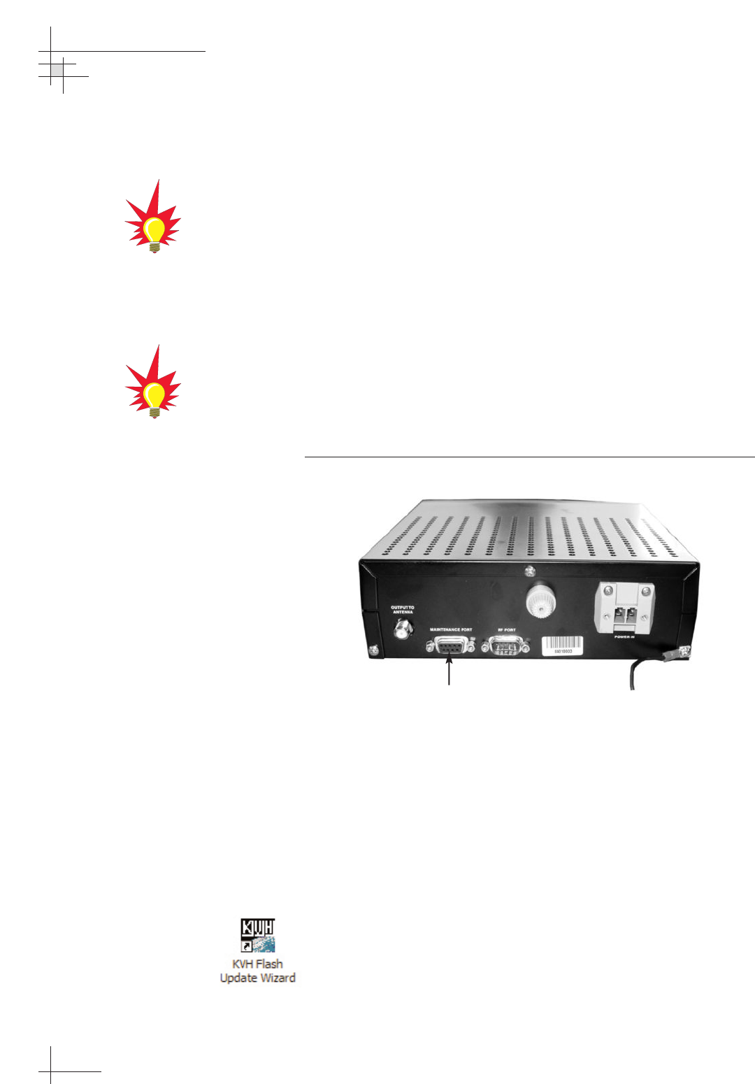
4.5 Computer Diagnostics
TracVision G8 provides advanced diagnostic readouts viewed on
a PC with an RS-232 serial communication port. If you are unable
to isolate a system problem, set up for computer diagnostics as
described below. System problems will most likely be found
through the diagnostic readouts.
The diagnostics procedure requires either the KVH Flash Update
Wizard or Windows HyperTerminal. Use the settings appropriate
to your application.
1. Connect one end of the PC data cable to the DB9
maintenance port connector on the rear of the MCU.
Connect the other end to the serial port on your PC
(a 9-pin/25-pin connector adapter may be needed for
some PCs).
Figure 4-3
MCU Maintenance Port
2. If you are using HyperTerminal, open HyperTerminal
and establish the following settings:
• Bits per second: 9600
• Data bits: 8
• Parity: None
• Stop bits: 1
• Flow control: None
If you are using the KVH Flash Update Wizard, double-
click the “KVH Flash Update Wizard” shortcut on your
computer’s desktop to start the wizard. Then go to the
“Select board to flash” screen.
54-0198
90
TracVision G8 Owner’s Manual - Guide to Technical Information
Maintenance Port
You can download the latest KVH
Flash Update Wizard at
www.kvh.com/wizard.
If your computer does not have a
DB9 serial COM port, you can use
the following USB-to-RS232
adapter:
IOGear part number GUC232A
(visit www.iogear.com)

3. Apply power to the TracVision G8 system and allow the
system to complete full initialization. Data should be
scrolling on the PC display to identify any system
problems detected. If no data appears, recheck your
connections and setup.
4.6 Maintenance Port Antenna
Commands
TracVision G8 system antenna commands are detailed in
Appendix D on page 129.
Troubleshooting
54-0198
91

Maintenance
54-0198
93
5 – Maintenance
This section identifies system components that may be replaced in the
field, details how to replace those components, and lists preventive
maintenance routines.
Contents
5.1 Warranty/Service Information . . . . . . . . . . . . . . . . . . . . . . . . . . . . . . .95
5.2 Preventive Maintenance . . . . . . . . . . . . . . . . . . . . . . . . . . . . . . . . . . .95
5.3 TracVision G8 Field Replaceable Units . . . . . . . . . . . . . . . . . . . . . . . .96
5.4 Accessing Antenna Components Through the Hatch . . . . . . . . . . . . .98
5.5 Replacing the PCB Module Fuse . . . . . . . . . . . . . . . . . . . . . . . . . . . . .98
5.6 Replacing the PCB Module . . . . . . . . . . . . . . . . . . . . . . . . . . . . . . . . .99
5.7 Replacing the RF PCB . . . . . . . . . . . . . . . . . . . . . . . . . . . . . . . . . . . .101
5.8 Replacing the Internal Sensor . . . . . . . . . . . . . . . . . . . . . . . . . . . . .103
5.9 Replacing the Azimuth Gyro . . . . . . . . . . . . . . . . . . . . . . . . . . . . . . .104
5.10 Replacing the Elevation Gyro . . . . . . . . . . . . . . . . . . . . . . . . . . . . . .106
5.11 Replacing the Azimuth Motor . . . . . . . . . . . . . . . . . . . . . . . . . . . . . .107
5.12 Replacing the Azimuth Belt . . . . . . . . . . . . . . . . . . . . . . . . . . . . . . . .109
5.13 Replacing the Elevation Motor . . . . . . . . . . . . . . . . . . . . . . . . . . . . .110
5.14 Replacing the Elevation Belt . . . . . . . . . . . . . . . . . . . . . . . . . . . . . . .112
5.15 Replacing the Skew Motor . . . . . . . . . . . . . . . . . . . . . . . . . . . . . . . .113
5.16 Replacing the Skew Belt . . . . . . . . . . . . . . . . . . . . . . . . . . . . . . . . . .116
5.17 Replacing the LNB . . . . . . . . . . . . . . . . . . . . . . . . . . . . . . . . . . . . . .117
5.18 Replacing the LNB/Feed Tube Assembly . . . . . . . . . . . . . . . . . . . . .118
5.19 Preparing for Shipment . . . . . . . . . . . . . . . . . . . . . . . . . . . . . . . . . .120
Maintenance
54-0198
95
5.1 Warranty/Service Information
For information on KVH warranty, repair, and liability policies,
please refer to the complete warranty statement provided with
the product. If you have any questions, please call your local
authorized dealer/installer or distributor, or contact KVH or
KVH Europe directly.
IMPORTANT! Before returning the product, be sure to obtain
an RMA number from KVH’s Technical Support Department
and write the number on the outside of the box. Shipments
received without an RMA number will be returned to you at
your expense.
5.2 Preventive Maintenance
TracVision G8 requires minimal preventive maintenance. The
following tasks are sufficient to maintain peak performance.
Monthly
• Wash the exterior of the radome and baseplate assembly
with fresh water; a mild detergent may be added to
remove grime. Use caution when spraying the radome
directly with high-pressure water.
•Do not apply abrasive cleaners or volatile solvents such as
acetone to the ABS radome.
•Check all connectors at the MCU and receiver. Remove
connectors and examine for signs of corrosion; clean as
needed.
Semi-Annually
•Remove the radome and examine the interior of the
antenna unit for signs of corrosion, loose connections, or
frayed or broken wires.
• Check the connectors at the antenna baseplate. Remove
connectors and examine for signs of corrosion; clean as
needed.
When cleaning the radome, avoid
any compounds that react with
plastic.
Detailed information on KVH’s
global support program and how to
contact KVH or a dealer near you is
available at www.kvh.com/
global_support.
54-0198
96
TracVision G8 Owner’s Manual - Guide to Technical Information
5.3 TracVision G8 Field
Replaceable Units
If you experience an operating problem or need technical
assistance, please contact your local authorized TracVision G8
dealer/installer or distributor. If one is not located nearby,
contact KVH or KVH Europe directly at the phone, fax, or e-mail
listings on the first page of this manual. Field replaceable units
that can be serviced in the field are listed in Table 5-1.
Table 5-1
TracVision G8 Field Replaceable Units
FRU Part Number
Radome 02-1255
PCB Module 02-1264
RF PCB 02-1342
Master Control Unit (MCU) 02-1265
Azimuth or Elevation Gyro 19-0222
Internal Sensor (with GPS) 02-1266
Azimuth Motor 02-1351
Azimuth Belt 24-0187-0161
Elevation Motor 02-1350
Elevation Belt 24-0105-0137
Skew Motor 19-0110
Skew Belt 24-0124-0144
Standard Circular Dual LNB 02-0870
Standard Circular Dual LNB/Feed Tube Assembly 02-1282-01
DLA Circular Dual LNB Assembly 02-0870-01
DLA Circular Dual LNB/Feed Tube Assembly 02-1282-03
Linear Quad LNB Assembly 02-1323
Linear Quad LNB/Feed Tube Assembly 02-1282-04
Data/power Cable 32-0744-0100
PC Cable 32-0628-06
Receiver Ground Wire 32-0583-50
MCU Fuse 16-0029-15
PCB Module Fuse 16-0029-05
The serial number for your
TracVision G8 will be required
during any troubleshooting or
service calls. You will find the serial
number on the first page of this
manual. (You can also find the
serial number by using the MCU’s
Get Antenna Status mode; see
“Antenna Status Data Screens” on
page 66
for details.)
To help us continually improve the
quality and reliability of our
systems, please return any failed
component to KVH or KVH Europe
(in care of the mailing address
listed on the first page of this
manual) after you receive your
replacement part.
All field replaceable units may be removed and replaced on site
using common hand tools. Other service must be done by your
authorized dealer/installer, distributor, or by KVH. Evidence of
tampering or unauthorized repairs will void the warranty.
The following sections provide step-by-step procedures for
replacing field replaceable units. Figures 5-1 and 5-2 show the
locations of a number of components within the antenna unit.
Figure 5-1
TracVision G8 Antenna Unit (Front View)
Figure 5-2
TracVision G8 Antenna Unit (Rear View)
Maintenance
54-0198
97
TracVision G8 components
receive power from multiple
sources. Do not open any
electrical assemblies or attempt
servicing until receiver power
and vessel input power are
disconnected.
PCB Module
Feed Tube
Reflector
LNB
Baseplate
Internal
Sensor
(w/ GPS)
Skew Motor
(Linear Quad only)
Azimuth
Motor
Frame
Elevation
Motor
5.4 Accessing Antenna Components
Through the Hatch
You can access all field replaceable units through the large hatch
on the antenna baseplate. You do not need to remove the
radome. To remove the hatch cover, simply remove the eleven
M4 screws securing the hatch cover to the baseplate.
Figure 5-3
Baseplate Access Hatch
5.5 Replacing the PCB Module Fuse
The PCB module is equipped with a 5-amp, 125-volt fast-blow
fuse. If this fuse has blown or been broken, simply unscrew the
fuse holder cap on the PCB module and replace the fuse.
Figure 5-4
PCB Module Fuse Location
54-0198
98
TracVision G8 Owner’s Manual - Guide to Technical Information
M4 Screws
(x 11)
Fuse Holder Cap
5.6 Replacing the PCB Module
1. Follow the steps in Section 4.5, “Computer Diagnostics,” on
page 90 to connect a PC to the MCU’s maintenance port
and apply power to the antenna unit.
2. Record the serial number for later re-entry.
3. Disconnect power from the antenna unit and the receiver.
4. Disconnect all cables from the PCB module. Use a 7⁄16"
wrench to carefully disconnect the two RF cables.
Figure 5-5
PCB Module Connections
5. Loosen the four captive screws securing the PCB module
to the antenna frame. Remove the PCB module.
6. Attach the new PCB module to the antenna frame using
the module’s four captive screws.
Maintenance
54-0198
99
RF Cable
Connectors Captive
Screws
Captive
Screws
Other Cable
Connectors
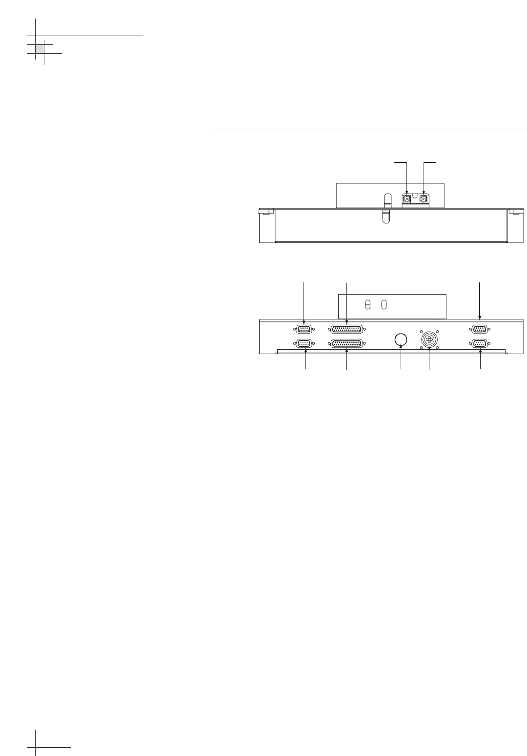
7. Reconnect the cables that you removed in Step 4. Be
sure to reconnect all cables in their proper positions.
Figure 5-6 shows the proper connector assignments.
Figure 5-6
PCB Module Connectors
8. Apply power to the antenna unit.
9. Using the PC connected to the maintenance port, type
HALT then press Enter.
10. Type DEBUGON then press Enter.
11. Type =TVG8SS then press Enter.
12. Type =SERNUM,<serial number>, where <serial
number> = the serial number you recorded in Step 2.
Then press Enter.
13. Type ZAP then press Enter to restart/reinitialize the
system.
14. Calibrate the antenna gyros as explained in “Calibrating
the Gyros” on page 105.
15. Reinstall your selected satellites as explained in Section 2.7,
“Installing Satellites Using the MCU,” on page 42.
54-0198
100
TracVision G8 Owner’s Manual - Guide to Technical Information
POWER
ELEVATI ON GYROINTERNAL SENSOR SKEW MOTOR
ELEVATION & AZ IMUTH MOTORS
AZIMUTH/ROLL GYROLIMIT SWITCHES
FUSE
Limit
Switches
Internal
Sensor
Azimuth
Gyro
Elevation
Gyro
Power
Elevation & Azimuth
Motors
Skew MotorFuse
To LNB
BOTTOM
TOP
RF1 From IRD
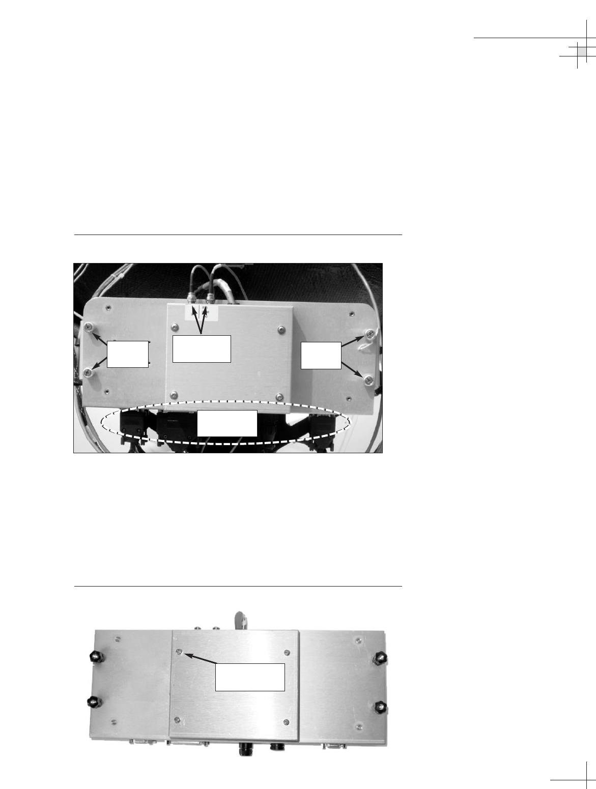
5.7 Replacing the RF PCB
1. Disconnect power from the antenna unit and the receiver.
The RF PCB is protected within a metal enclosure that is
fastened to the antenna frame. This PCB module, which
contains the main and RF PCBs, must be removed to gain
access to the RF PCB.
2. Disconnect all cables from the PCB module. Use a 7⁄16"
wrench to carefully disconnect the two RF cables.
Figure 5-7
PCB Module Connetions
3. Loosen the four captive screws securing the PCB module
to the antenna frame. Remove the PCB module and bring
it belowdecks for bench work.
4. Remove the four #6-32 screws and flat washers
securing the RF PCB cover to the PCB module. Set
aside the RF PCB cover.
Figure 5-8
RF PCB Cover
Maintenance
54-0198
101
#6-32 Screws
(x 4)
RF Cable
Connectors Captive
Screws
Captive
Screws
Other Cable
Connectors
5. Disconnect the Molex connector from the RF PCB.
Figure 5-9
RF PCB
6. Using a 1⁄4" nut driver/socket, remove the four #6-32
standoffs securing the RF PCB to the PCB module (see
Figure 5-9). Remove the old RF PCB.
7. Apply a drop of Loctite threadlocker to the screw ends
of the four standoffs and secure the new RF PCB to the
PCB module with the standoffs.
8. Reconnect the Molex connector that you removed in
Step 5, and reinstall the PCB cover that you removed in
Step 4.
9. Reattach the PCB module to the antenna frame using
the module’s four captive screws.
10. Reconnect the cables that you removed in Step 2. Be
sure to reconnect all cables in their proper positions.
Figure 5-6 on page 100 shows the proper connector
assignments.
54-0198
102
TracVision G8 Owner’s Manual - Guide to Technical Information
Molex
Connector
Standoffs
(x 4)
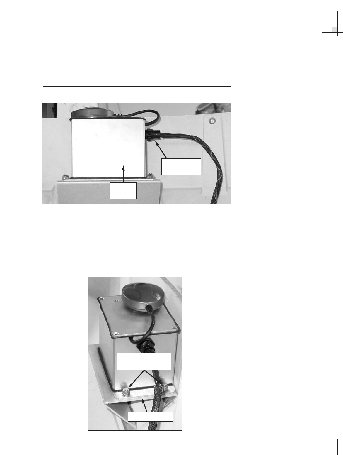
5.8 Replacing the Internal Sensor
1. Disconnect the sensor cable from the internal sensor
assembly.
Figure 5-10
Internal Sensor Assembly (Side View)
2. Using a 3⁄8" nut driver/socket, remove the four
#10-32 self-locking nuts and flat washers securing the
internal sensor assembly to the sensor bracket. Remove
the old internal sensor.
Figure 5-11
Internal Sensor Assembly (Top View)
Maintenance
54-0198
103
Sensor Cable
Connector
#10-32 Self-locking
Nuts (x 4)
Sensor Bracket
Internal
Sensor
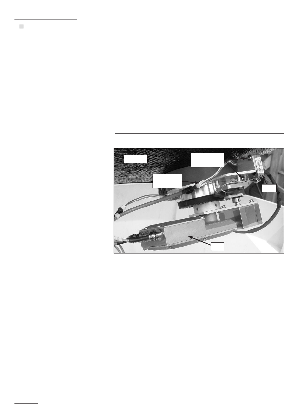
3. Install the new internal sensor. Secure in place with the
nuts/washers that you removed in Step 2 and reconnect
the sensor cable.
4. With Autocalibration set to “ON,” the sensor will calibrate
itself when you power up the antenna and maneuver the
vessel. The factory default setting for Autocalibration is
“ON” (see “Selecting Autocalibration” on page 78).
5.9 Replacing the Azimuth Gyro
1. Disconnect the gyro cable from the in-line connector.
Figure 5-12
Azimuth Gyro
2. Remove the two M2.5 screws securing the gyro to the
LNB/feed tube assembly. Remove the old gyro.
3. Apply a drop of Loctite threadlocker to the threads of the
screws that you removed in Step 2. Install the new
azimuth gyro and secure in place with the two screws.
4. Connect the new gyro cable to the in-line connector that
you disconnected in Step 1.
5. Calibrate the gyro as described in “Calibrating the Gyros”
on page 105.
54-0198
104
TracVision G8 Owner’s Manual - Guide to Technical Information
Gyro Cable
Connector
M2.5 Screws
(x 2)
Gyro
LNB
Reflector
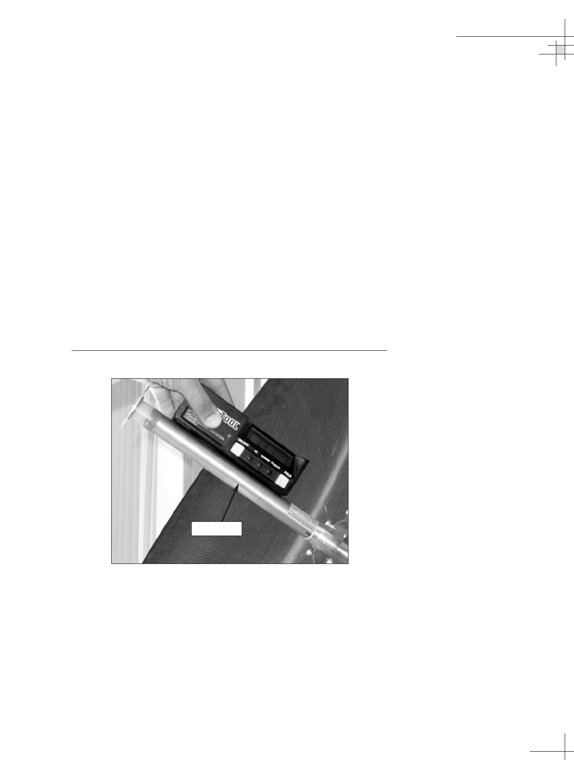
Calibrating the Gyros
To calibrate the azimuth and elevation gyros, follow the steps
below.
1. Follow the steps in Section 4.5, “Computer Diagnostics,” on
page 90 to connect a PC to the MCU’s maintenance port
and apply power to the antenna unit.
2. Type HALT then press Enter while the system is
performing the limit switch initialization routine. The
system will complete the initialization function by finding
the azimuth and elevation switch limits and then go to the
home position.
3. Type DEBUGON then press Enter to enter the Debug
Mode.
4. Type EL,300 then press Enter.
5. Using a digital level (or equivalent), measure and record
the angle of the feed tube, as shown in Figure 5-13.
Figure 5-13
Measuring Feed Tube Angle
6. Type =CALUP,XX.X, where XX.X is the number you
recorded in Step 5. Then press Enter.
7. Type =CALGYRO then press Enter. Verify that the
Antenna Gyro Azimuth scale factor is between -0.00090
and -0.00110 and the Antenna Gyro Elevation scale factor
is between 0.00090 and 0.00110.
8. Type ZAP then press Enter to restart/reinitialize the
system.
Maintenance
54-0198
105
Feed Tube
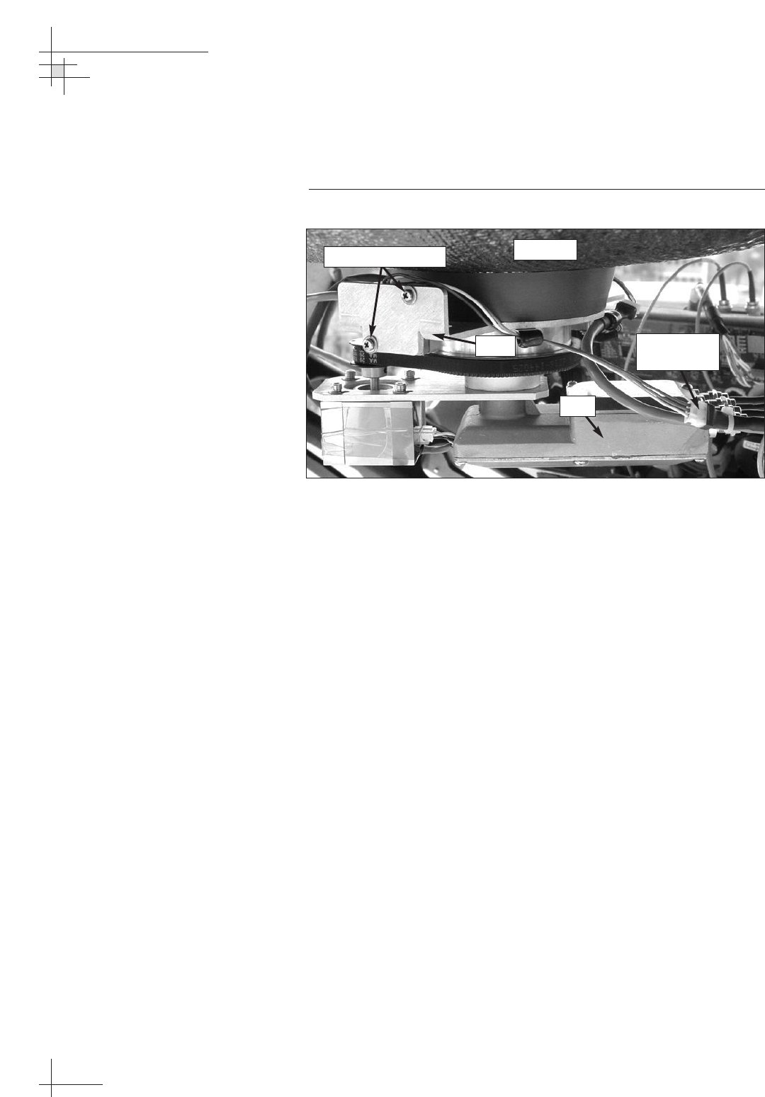
5.10 Replacing the Elevation Gyro
1. Disconnect the gyro cable from the in-line connector.
Figure 5-14
Elevation Gyro
2. Remove the two M2.5 screws securing the gyro to the
LNB/feed tube assembly. Remove the old gyro.
3. Apply a drop of Loctite threadlocker to the threads of the
screws that you removed in Step 2. Install the new
elevation gyro and secure in place with the two screws.
4. Connect the new gyro cable to the in-line connector that
you disconnected in Step 1.
5. Calibrate the gyro as described in “Calibrating the Gyros”
on page 105.
54-0198
106
TracVision G8 Owner’s Manual - Guide to Technical Information
Gyro Cable
Connector
M2.5 Screws (x 2)
Gyro
LNB
Reflector
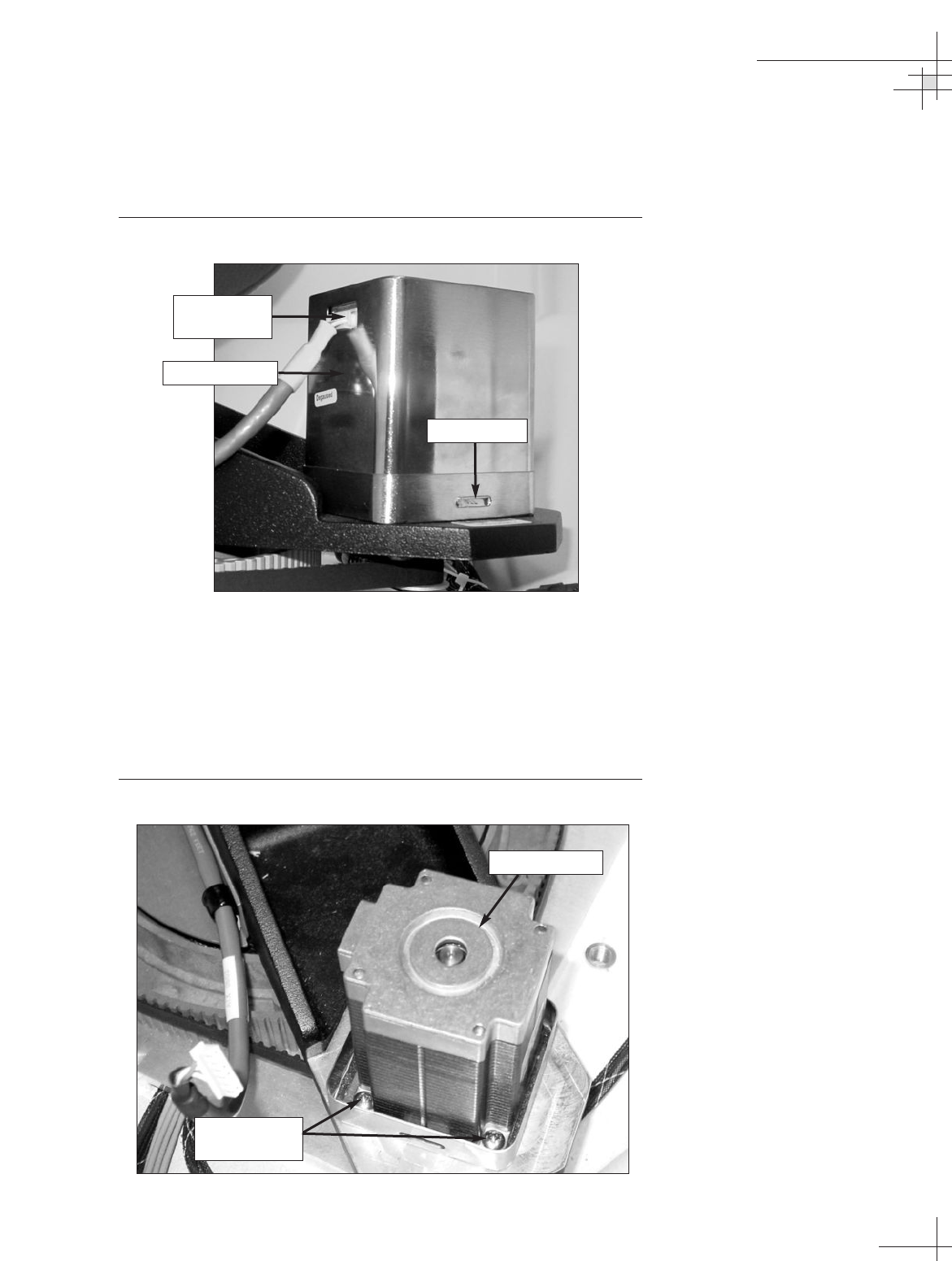
5.11 Replacing the Azimuth Motor
1. Disconnect the motor cable from the azimuth motor.
Figure 5-15
Azimuth Motor Cable
2. Remove the motor shield by pressing on the two sides of
the shield above the release tabs.
3. Remove the four #8-32 screws and locking nuts securing
the motor to the antenna frame. Remove the old azimuth
motor.
Figure 5-16
Azimuth Motor (Shield Removed)
Maintenance
54-0198
107
#8-32 Screws
(x 4)
Azimuth Motor
Motor Cable
Connector
Azimuth Motor
Release Tab
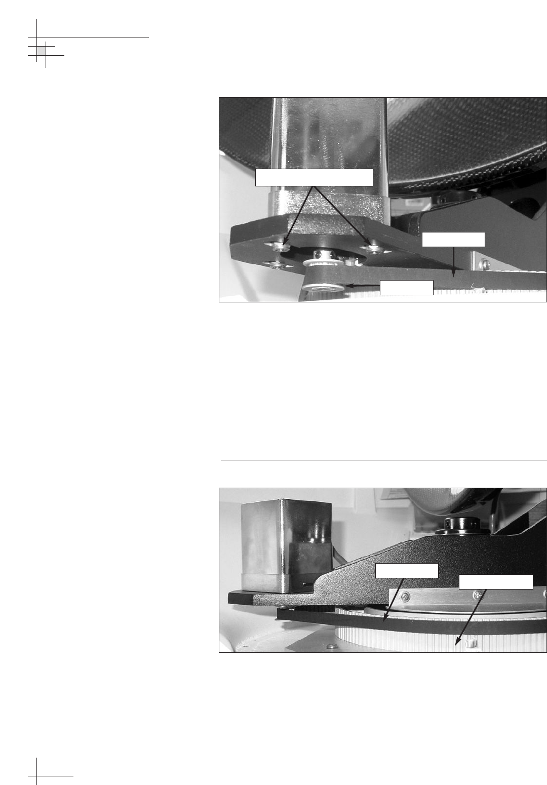
Figure 5-17
Azimuth Motor and Belt
4. Install the new azimuth motor with the belt positioned
around the outer lip of the motor hub (see Figure 5-17).
Reinstall the screws and locking nuts that you removed in
Step 3, but do not tighten them yet.
5. Slide the motor until the belt is tight around the motor
hub and azimuth pulley. Then tighten the screws and
locking nuts. Some readjustment may be necessary if the belt
tension results in excessive vibration.
Figure 5-18
Azimuth Belt
6. Reinstall the shield that you removed in Step 2.
7. Reconnect the motor cable that you removed in Step 1.
54-0198
108
TracVision G8 Owner’s Manual - Guide to Technical Information
#8-32 Locking Nuts (x 4)
Motor Hub
Azimuth Belt
Azimuth Belt
Azimuth Pulley
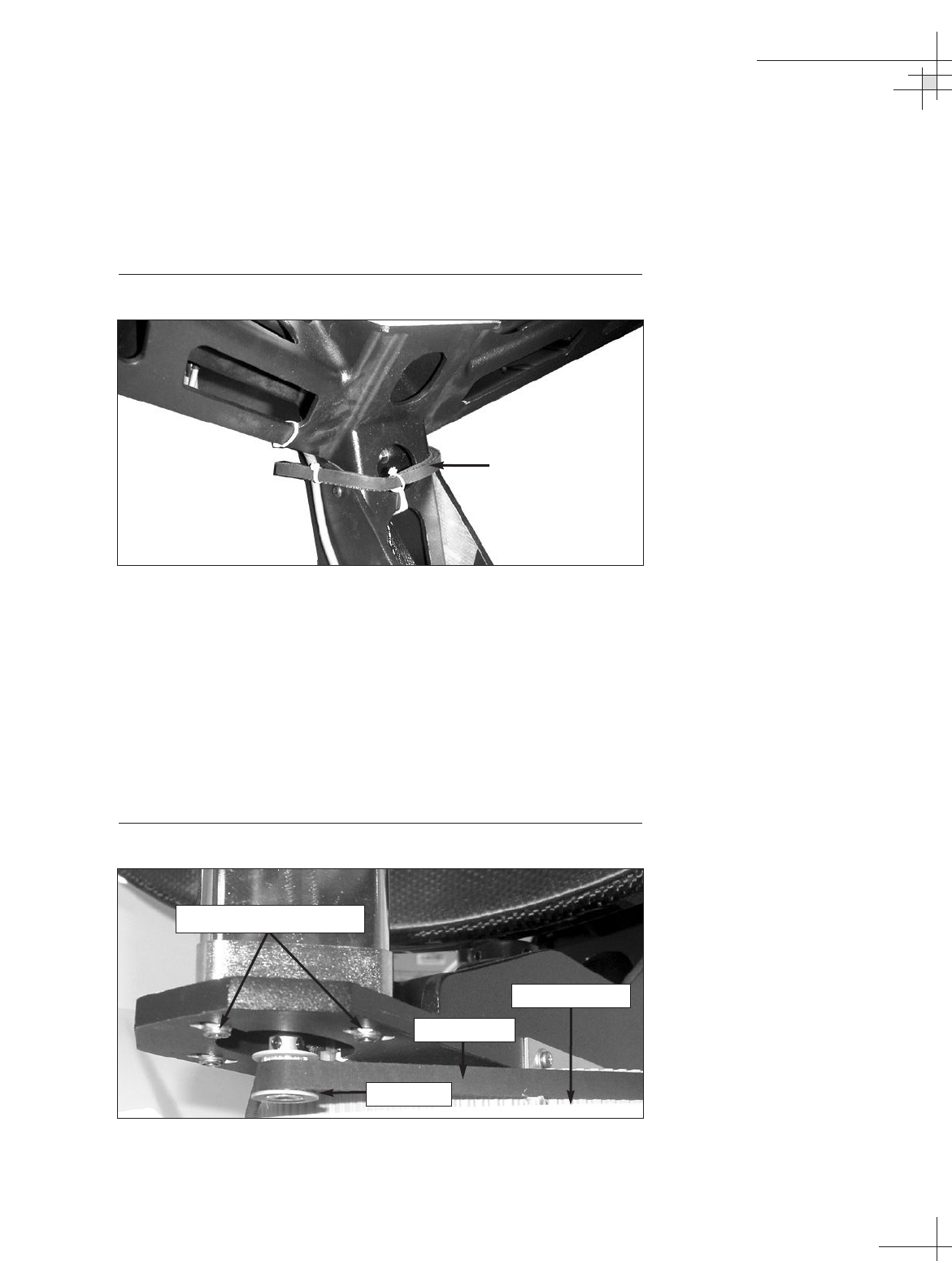
5.12 Replacing the Azimuth Belt
1. Cut and discard the old belt.
2. Cut the tie-wraps securing the spare belt to the antenna
frame.
Figure 5-19
Spare Azimuth Belt Attached to Frame
3. Carefully work the spare belt around the azimuth motor
hub and around the azimuth pulley. Ensure that the teeth
are on the inside of the belt. Once the belt is in place,
work it back and forth to ensure that the belt is aligned
and the teeth are engaged with the pulley and motor hub.
Ensure that the belt fits tightly around the pulley and hub.
(To tighten the belt, loosen the azimuth motor’s #8-32
locking nuts, slide the motor until the belt is tight, then
retighten the locking nuts.)
Figure 5-20
Azimuth Belt
Maintenance
54-0198
109
Spare Belt
#8-32 Locking Nuts (x 4)
Motor Hub
Azimuth Belt
Azimuth Pulley
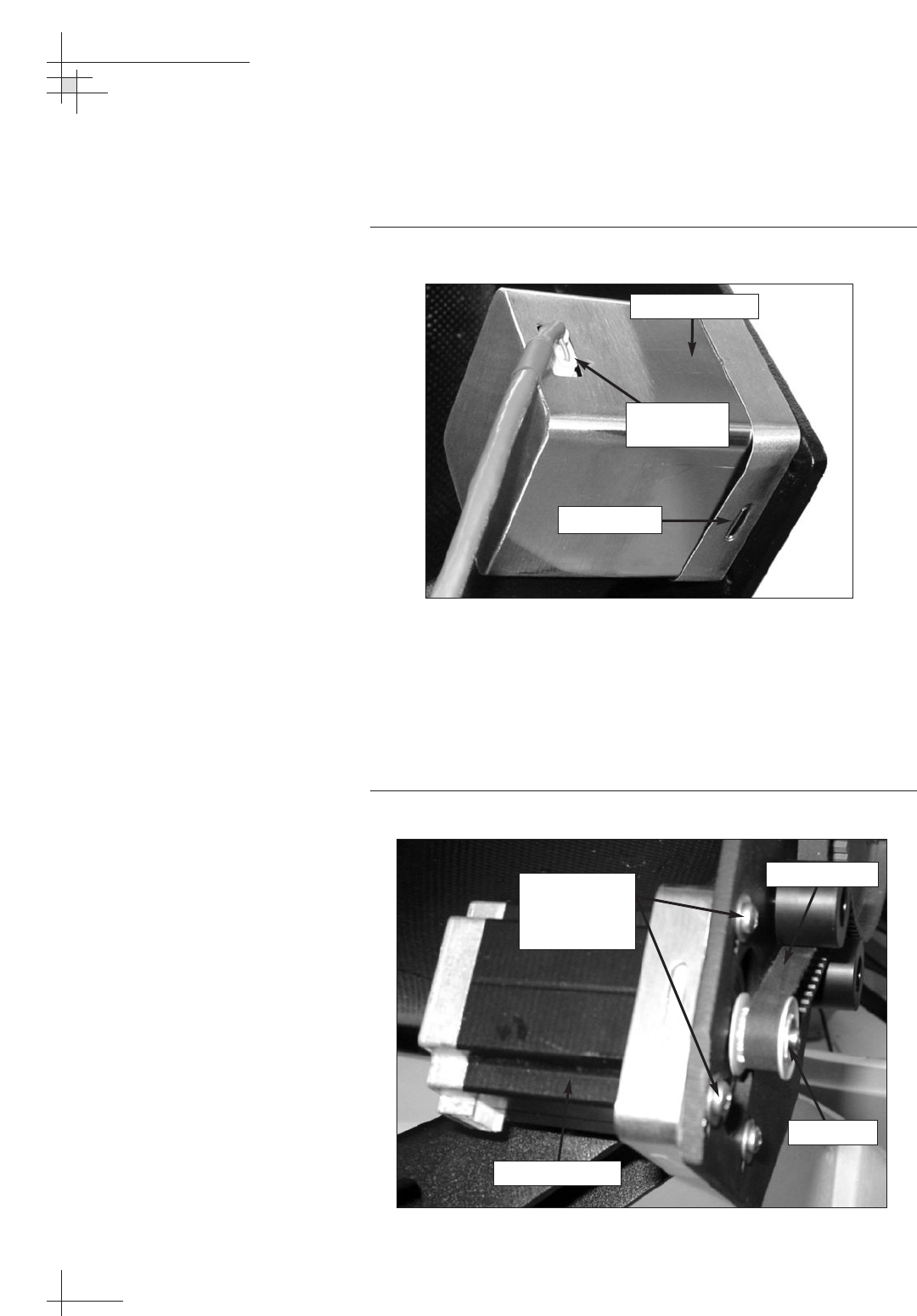
5.13 Replacing the Elevation Motor
1. Disconnect the motor cable from the elevation motor.
Figure 5-21
Elevation Motor Cable
2. Remove the motor shield by pressing on the two sides of
the shield above the release tabs.
3. Remove the four #8-32 screws and washers securing the
motor to the antenna frame. Remove the old elevation
motor.
Figure 5-22
Elevation Motor (Shield Removed)
54-0198
110
TracVision G8 Owner’s Manual - Guide to Technical Information
Elevation Motor
Release Tab
#8-32 Screws
and Washers
(x 4)
Elevation Motor
Motor Hub
Elevation Belt
Motor Cable
Connector
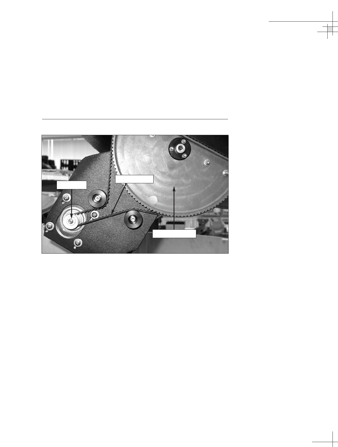
4. Install the new elevation motor with the belt positioned
around the outer lip of the motor hub. Reinstall the
screws and washers that you removed in Step 3, but do
not tighten them yet.
5. Slide the motor until the belt is tight around the motor
hub and elevation pulley. Tighten the screws. Some
readjustment may be necessary if the belt tension results in
excessive vibration.
Figure 5-23
Elevation Belt
6. Reinstall the shield that you removed in Step 2.
7. Reconnect the motor cable that you removed in Step 1.
Maintenance
54-0198
111
Elevation Pulley
Elevation Belt
Motor Hub
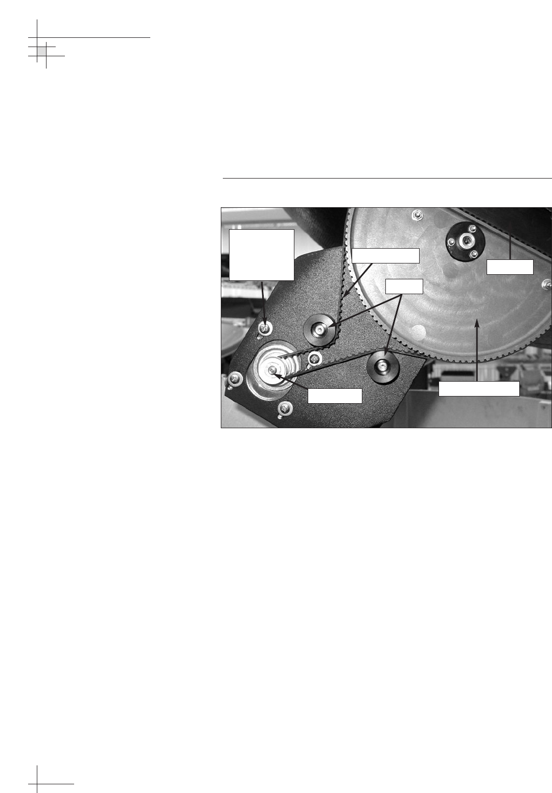
5.14 Replacing the Elevation Belt
1. Loosen (do not remove) the four #8-32 screws securing
the motor to the antenna frame until the motor is free to
slide upward. Raise the motor to the top of the slots and
retighten the screws to hold it in place.
Figure 5-24
Elevation Belt
2. Roll the belt over the motor hub, then over the elevation
pulley. Discard the old belt.
3. Carefully work the new belt around the elevation pulley,
between the rollers, and around the motor hub. Ensure
that the teeth are on the inside of the belt. Once the belt is
in place, work it back and forth to ensure that the belt is
aligned and the teeth are engaged with the pulley.
4. Loosen the #8-32 screws and slide the motor downward
until the belt is tight around the motor hub and the
elevation pulley. Some readjustment may be necessary if the
belt tension results in excessive vibration.
5. Tighten the motor screws.
54-0198
112
TracVision G8 Owner’s Manual - Guide to Technical Information
Elevation Belt
Elevation Pulley
Reflector
Rollers
Motor Hub
#8-32
Screws and
Washers
(x 4)
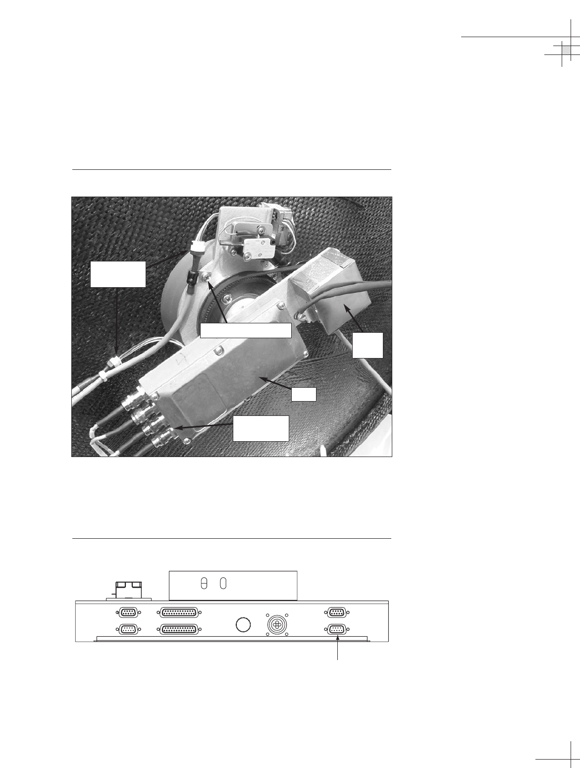
5.15 Replacing the Skew Motor
(Linear Quad LNB Systems Only)
1. Using a 7⁄16" wrench, carefully disconnect the four RF
cables from the LNB.
Figure 5-25
Linear Quad LNB/Feed Tube Assembly
2. Disconnect the elevation and azimuth gyro cables from
the in-line connectors.
3. Disconnect the skew motor cable from the PCB module.
Figure 5-26
Skew Motor Cable Connector on PCB Module
Maintenance
54-0198
113
RF Cable
Connectors
LNB
Skew
Motor
#8-32 Screws (x 4)
POWER
ELEVATION GYROINTERNAL SENSOR SKEW MOTOR
ELEVATION & AZI MUTH MOTORS
AZIMUTH/ROLL GYROLIMIT SWITCHES
FUSE
Skew Motor
Cable Connector
Gyro Cable
Connectors
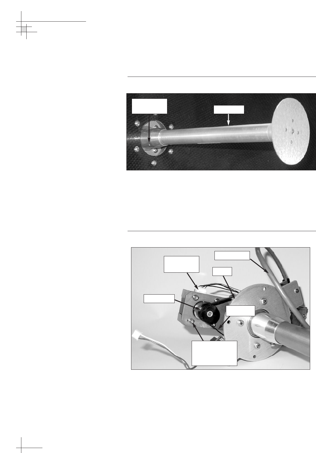
4. Using a 5⁄64" allen key, loosen the two #8-32 set screws
securing the feed tube in the LNB/feed tube assembly
collar. Remove the feed tube.
Figure 5-27
Removing the Feed Tube
5. Remove the four #8-32 screws securing the LNB/feed
tube assembly to the reflector base (see Figure 5-25).
Remove the LNB/feed tube assembly.
6. Disconnect the motor cable from the skew motor.
Figure 5-28
Skew Motor and Belt
7. Using a 2.5 mm allen wrench, remove the four M3 cap
screws and #4 washers securing the motor to the
LNB/feed tube assembly (see Figure 5-28). Remove the
old skew motor.
54-0198
114
TracVision G8 Owner’s Manual - Guide to Technical Information
Pulley
Motor Hub
M3 Cap Screws
and #4 Washers
(x 4)
Motor Cable
Connector
Motor Cable
Skew Belt
Feed Tube
#8-32 Set
Screws (x 2)
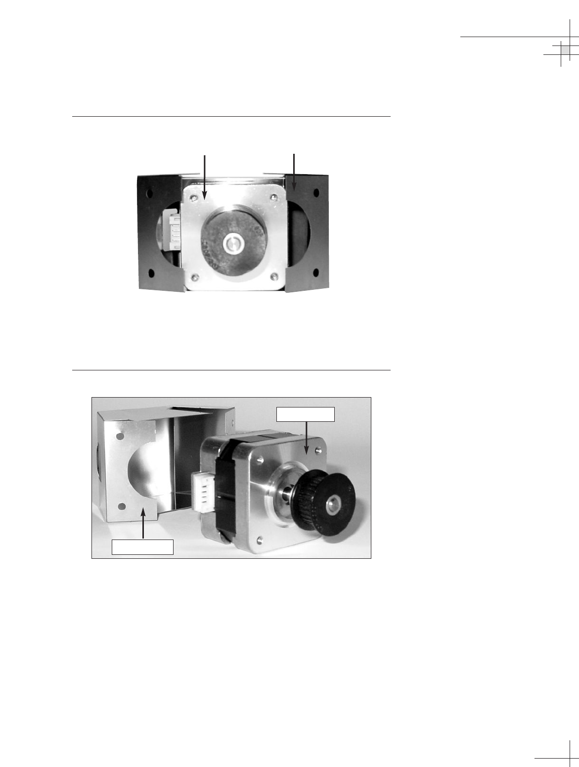
8. Gently extend the two sides of the motor shield and
remove the shield from the old skew motor.
Figure 5-29
Removing the Skew Motor Shield
9. Place the new skew motor inside the motor shield. The
motor’s connector should pass through the small opening
in the shield.
Figure 5-30
Installing the Skew Motor Shield
10. Attach the new skew motor to the LNB/feed tube
assembly with the belt positioned around the outer lip of
the motor hub. Ensure that the motor’s connector is facing
the motor cable, as shown in Figure 5-28. Reinstall the
washers and screws that you removed in Step 7, but do
not tighten them yet.
11. Slide the motor to adjust the belt tension until the belt
teeth fully engage the motor hub and the pulley. Tighten
the motor cap screws. Some readjustment may be necessary if
the belt tension results in excessive vibration.
Maintenance
54-0198
115
Skew Motor Motor Shield
Skew Motor
Motor Shield

12. Reconnect the motor cable that you removed in Step 6.
13. Apply a small amount of Loctite threadlocker to the
threads of the four #8-32 screws that you removed in
Step 5.
14. Carefully reattach the LNB/feed tube assembly to the
antenna reflector and secure in place with the four #8-32
screws.
15. Apply a small amount of Loctite threadlocker to the
threads of the two #8-32 set screws that you loosened in
Step 4.
16. Carefully insert the feed tube into the feed tube assembly
collar and secure in place with the #8-32 set screws.
17. Reconnect the cables you removed in Steps 1, 2, and 3.
5.16 Replacing the Skew Belt
(Linear Quad LNB Systems Only)
1. Follow Steps 1 through 5 of the previous section.
2. Using a 2.5 mm allen wrench, loosen (do not remove) the
four M3 cap screws securing the motor to the bracket
until the motor is free to slide back and forth. Slide the
motor toward the pulley to loosen the belt.
Figure 5-31
Skew Motor and Belt
54-0198
116
TracVision G8 Owner’s Manual - Guide to Technical Information
Pulley
Motor Hub
M3 Cap Screws
and #4 Washers
(x 4)
Motor Cable
Connector
Motor Cable
Skew Belt
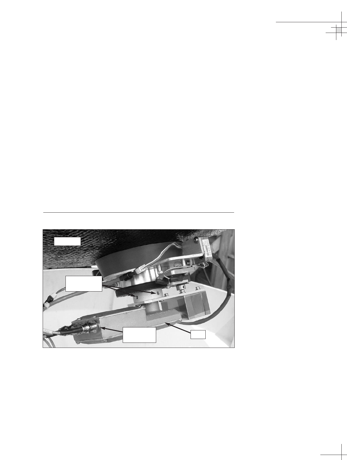
3. Roll the belt over the motor hub, then over the pulley.
Remove and discard the old belt.
4. Place the new belt around the pulley and around the motor
hub. Ensure that the teeth are on the inside of the belt.
5. Slide the motor back until the belt is set at the proper
tension. Adjust the belt tension until the belt teeth fully
engage the motor hub and the pulley. Some readjustment
may be necessary if the belt tension results in excessive
vibration.
6. Once the belt is at the proper tension, tighten the motor’s
four M3 cap screws.
7. Follow Steps 13 through 17 of the previous section.
5.17 Replacing the LNB
1. Using a 7⁄16" wrench, carefully disconnect the RF cables
from the LNB.
Figure 5-32
LNB (Linear Quad Version Shown)
2. Using a 5⁄64" allen key, loosen the two #8-32 set screws
securing the LNB in place. Remove the old LNB.
3. Install the new LNB and secure in place with the #8-32 set
screws.
4. Using a 7⁄16" wrench, carefully reattach the RF cables that
you removed in Step 1.
Maintenance
54-0198
117
LNB
Reflector
RF Cable
Connectors
#8-32 Set
Screws (x 2)
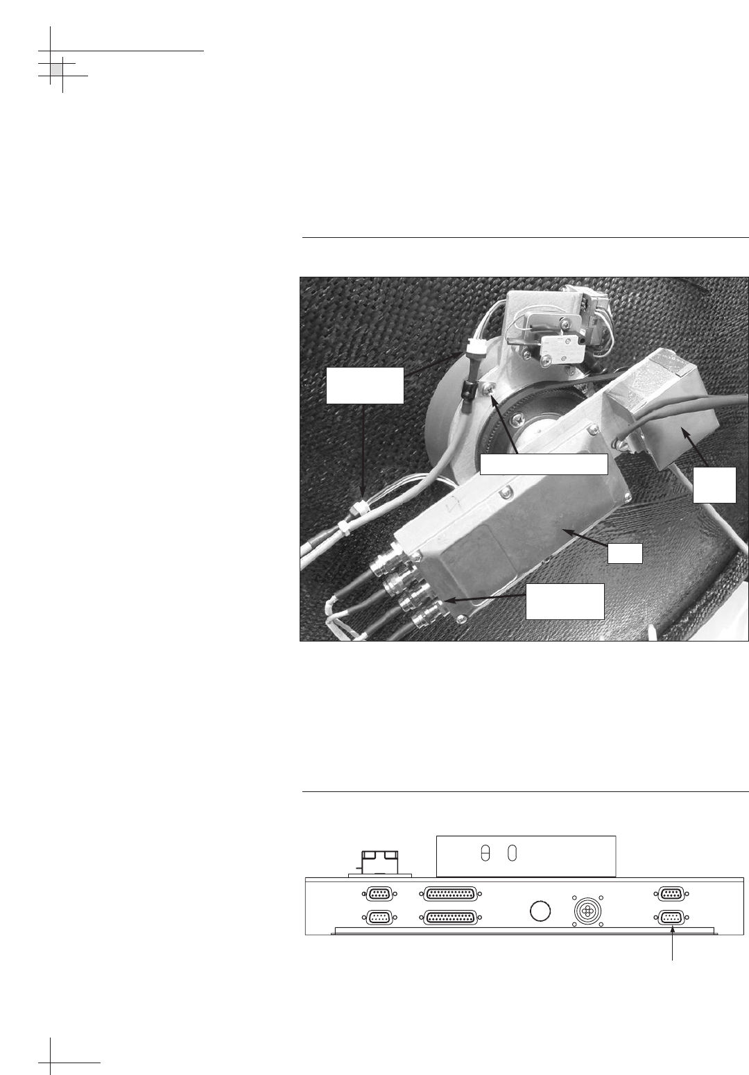
5.18 Replacing the LNB/Feed Tube
Assembly
1. Using a 7⁄16" wrench, carefully disconnect the RF cables
from the LNB.
Figure 5-33
LNB (Linear Quad version Shown)
2. Disconnect the azimuth and elevation gyro cables from
the in-line connectors.
3. Linear quad LNB systems only:
Disconnect the skew motor cable from the PCB module
(see Figure 5-34).
Figure 5-34
Skew Motor Cable Connector on PCB Module
54-0198
118
TracVision G8 Owner’s Manual - Guide to Technical Information
POWER
ELEVATION GYROINTERNAL SENSOR SKEW MOTOR
ELEVATION & AZI MUTH MOTORS
AZIMUTH/ROLL GYROLIMIT SWITCHES
FUSE
Skew Motor
Cable Connector
RF Cable
Connectors
LNB
Skew
Motor
#8-32 Screws (x 4)
Gyro Cable
Connectors
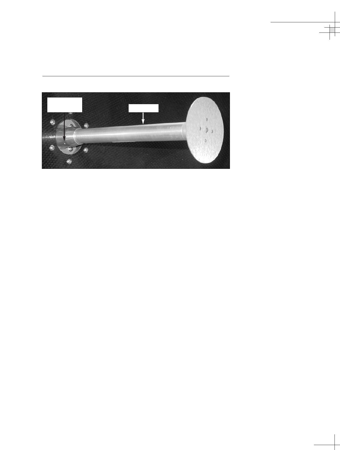
4. Using a 5⁄64" allen key, loosen the two #8-32 set screws
securing the feed tube in the LNB/feed tube assembly
collar. Remove the feed tube.
Figure 5-35
Removing the Feed Tube
5. Remove the four #8-32 screws securing the LNB/feed
tube assembly to the reflector base (see Figure 5-33).
Remove the LNB/feed tube assembly.
6. Apply a small amount of Loctite threadlocker to the threads
of the four #8-32 screws that you removed in Step 5.
7. Install the new LNB/feed tube assembly and secure in
place with the #8-32 screws.
8. Apply a small amount of Loctite threadlocker to the
threads of the two #8-32 set screws that you loosened in
Step 4.
9. Carefully insert the new feed tube into the feed tube
assembly collar and secure in place with the #8-32 set
screws.
10. Reconnect the cables you removed in Steps 1, 2, and 3.
Maintenance
54-0198
119
Feed Tube
#8-32 Set
Screws (x 2)
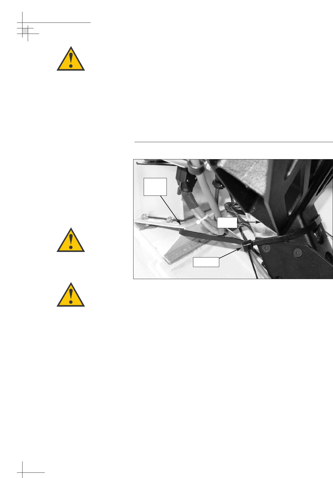
5.19 Preparing for Shipment
If you need to repack the antenna unit for shipment, the shipping
restraint that was removed during installation must be
reattached. Follow the steps below to reinstall the restraint and
get the antenna unit ready for shipping.
1. Using a heavy-duty tie-wrap (which was detached at the
time of installation), secure the antenna frame to the
internal sensor’s mounting bracket.
Figure 5-36
Azimuth Shipping Restraint
2. Place some foam between the reflector and the baseplate
to keep the reflector from moving.
3. Pack the TracVision G8 antenna unit in its original
package. Secure the box to a pallet to ensure upright
transport.
4. As detailed in the warranty accompanying this product, a
Return Material Authorization (RMA) number is required
prior to the return of the TracVision G8 system to KVH.
Contact the KVH Technical Support Department at
+1 401 847-3327 or via e-mail at techs@kvh.com to obtain
the RMA number. Please review your warranty to
familiarize yourself with all requirements, liabilities, and
policies.
54-0198
120
TracVision G8 Owner’s Manual - Guide to Technical Information
Tie-wrap
Sensor
Bracket
Frame
When rotating the azimuth
mechanism by hand, go slowly!
Hitting the mechanical stops with
excessive force will damage the
azimuth limit switch.
KVH is not liable for damage
caused by improper shipping.
Before returning the product, be
sure to obtain an RMA number
from KVH’s Technical Support
Department and write the
number on the outside of the
box. Shipments received without
an RMA number will be returned
to you at your expense.

Appendices
54-0198
121
Appendices
This section contains several appendices of supplemental information,
including a mounting template, startup data, and antenna commands.
Contents
A System Specifications . . . . . . . . . . . . . . . . . . . . . . . . . . . . . . . . . . .123
B MCU Flush Mount Panel Template . . . . . . . . . . . . . . . . . . . . . . . . . .125
C Startup Data Sequence . . . . . . . . . . . . . . . . . . . . . . . . . . . . . . . . . . .127
D Maintenance Port Antenna Commands . . . . . . . . . . . . . . . . . . . . . .129

System Specifications
54-0198
123
Appendix A
System Specifications
Physical Characteristics
Antenna Unit 39" (99 cm) h x 35" (89 cm) dia;
85 lbs (38.6 kg)
MCU 7.3" (18.5 cm) d x 8.2" (20.8 cm) w
x 2.6" (6.6 cm) h
Operating temperature -13°F to +130°F (-25°C to +55°C)
Storage temperature -40°F to +185°F (-40°C to +85°C)
Input Power
Input 9-36 VDC, 120 W max. (90 W typical)
Power to the antenna is galvanically
isolated from input power
Antenna System Performance
Minimum EIRP 44 dBW
Elevation range -15° to +85°
Azimuth range 720°
Tracking rate 30°/second
Position repeatability 0.1°
Skew control Automatic
GPS Internal
Antenna dish 32" (82 cm) dia
LNB Three variations:
• Standard circular dual LNB
• DLA circular dual LNB
• Linear quad LNB
Surge/sway/heave ±0.2 G
Shock 20 G, 11 msec
Vibration 0.9 G rms over 5-33 Hz
8.87"
(225 mm)
7.62"
(194 mm)
.63"
(16 mm)
3.08"
(78 mm)
1.83"
(46 mm)
.63"
(16 mm)
4x .19" (5 mm) Thru
4x R .63" (16 mm)
Appendix B
ADCU Flush Mount
Panel Template
(Scale 1:1)
Appendix B
MCU Flush
Mount Panel
Template
(Scale 1:1)
125

Startup Data Sequence
54-0198
127
Appendix C
Startup Data Sequence
The data on the following pages presents a sample startup
data sequence registered by the TracVision G8. This sequence
may vary based on the software version loaded onto the
TracVision G8 system. This data can be recorded using the
maintenance port and a PC.
TracVision G8 Controller Rev X - Ver X.XX - Serial number XXXXXXXX - HW Rev XX
*** Init RF Board ***
RF: S,A,H,U,V
RF: SATINSTALL,55,C,57,C
RF: L,A ------------------------------------------
Identifies Satellite A or B as currently
RF: SATCONFIG
loaded for acquisition
RF: F,A,12368,20000,67,0xFFFE,R,U,2 --------------
Satellite Configuration Data, Satellite A
RF: F,A,12368,20000,67,0xFFFE,R,U,2
RF: F,A,12238,20000,67,0xFFFE,L,U,2
RF: F,A,12238,20000,67,0xFFFE,L,U,2
RF: F,B,12370,20000,56,0x1004,R,U,3 --------------
Satellite Configuration Data, Satellite B
RF: F,B,12370,20000,56,0x1004,R,U,3
RF: F,B,12326,20000,56,0x1004,L,U,3
RF: F,B,12326,20000,56,0x1004,L,U,3
RF: RF PCB Version X.X---------------------------
Current RF software revision
RF COMM: PASS ------------------------------------
PASS is expected
RF: DVB/DSS 5
*** Init Antenna ***
*** NO GPS-Default Used ***----------------------
GPS has no lock upon power-up
GPS(DEFAULT),41,N, 71,W,083000.00
GPS: DSS_101 AZ = 220.8, EL = 33.4
GPS: DSS_119 AZ = 238.9, EL = 22.1
Saved Position: DSS_101 AZ = 232.2, EL = 37.7
Saved Position: DSS_119 AZ = 250.3, EL = 26.4
*** Limit Switch Test ***
Limit Switch Status: PASS------------------------
PASS is expected
*** Init Sensor ***
Sensor Status = @@
CAL SCORE = 100----------------------------------
Internal sensor data (100 = no field cal)
SENSOR: PASS -------------------------------------
PASS is expected
*** Init Rate Bias ***
RF: First lock -----------------------------------
Indicates satellite found that has the
RF: S,A,H,U,V
frequency, symbol rate, and FEC code
BIAS/RF: 2056 2134 2577
of the selected satellite
BIAS/RF: 2082 2053 2584
BIAS/RF: 2092 1990 2564
BIAS/RF: 2086 2029 2573
BIAS/RF: 2065 2082 2543

54-0198
128
TracVision G8 Owner’s Manual - Guide to Technical Information
BIAS/RF: 2057 2185 2583
BIAS/RF: 2032 2146 2572
Check cal gyro to rate bias
BiasLimit = 8.00 BiasFOGLimit = 0.0003 BiasCorrection = 5.00
Gyro Bias: Az = 2069.15, Cal Az = 2067.98 -------
Expected range is 1700-2300
Gyro Bias: El = 2050.04, Cal El = 2049.54
Gyro Bias: Az = 2069.15, El = 2050.04, Az FOG = 0.000300
Gyro Uncertainty: Az = 3.00, El = 3.00
GPS(ACTIVE),41.52,N, 71.28,W, 083000.00 ----------GPS position data (latitude, longitude, UTC)
GPS: DSS_101 AZ = 259.4, EL = 34.1 --------------Calculated satellite position based on GPS
*** Entering Tracking ***
+POS: 351.2 37.2 2531
%PRY: 1.2 -2.1 242.4 -------------------------
Internal sensor data (pitch, roll, and yaw)
*** Network ID Check ***-------------------------
Comparing the tracked satellite’s network ID to
+POS: 351.2 36.8 2554
the selected satellite’s network ID
%PRY: 1.4 -2.2 242.3
RF: Y,0xFFFE -------------------------------------
Indicates positive satellite identification
*** Tracking DSS_101 ***-------------------------
Identifies satellite currently tracked
Avg: 37.6 0.0 0.0 0.0 0.0
(TV broadcast image should be available)
Set con radius to 0.250 and 0.250
RF: IGNORE ID,0x0000
+POS: 352.0 35.8 2634
%PRY: 1.2 -2.2 242.2
Avg: 37.6 37.1 36.9 36.5 37.0
Saved Sat Pos: AZ = 233.0, EL = 37.0
+POS: 351.9 36.2 2606
%PRY: 1.2 -1.8 242.2
Rate Bias (Before): Az = 2.0692e+03 EL = 2.0500e+03
Rate Bias (After): Az = 2.0692e+03 EL = 2.0500e+03
Gyro Bias Residue: Az = -1.7217e-01 EL = 2.8887e-01
+POS: 352.0 36.1 2600
%PRY: 1.6 -2.3 242.3
+POS: 351.5 35.8 2576
%PRY: 1.2 -2.2 242.2
Conscan=>sleep: sat in 1.75 deg window.
+POS: 351.8 35.9 2611
%PRY: 1.2 -1.9 242.2
Sleeping
Old Gyro Bias: Az = 2069.20 EL = 2049.97
New Gyro Bias: Az = 2069.37 EL = 2049.68
RF: AGC=58792
Avg: 36.7 37.1 36.9 36.5 37.0
Saved Sat Pos: AZ = 232.6, EL = 36.9
+POS: 351.8 35.9 2610
%PRY: 1.2 -2.0 242.4

Maintenance Port Antenna Commands
54-0198
129
Appendix D
Maintenance Port
Antenna Commands
The TracVision G8 system commands are parsed when the
system receives an ASCII carriage return (Hex 0D). An ASCII line
feed (Hex 0A) is permitted but is ignored in any transmitted
command. All system responses are terminated with an ASCII
carriage return followed by a line feed and ending with either an
acknowledge character (ASCII > (Hex 3E)) or a not-acknowledge
character (ASCII ? (Hex 3F)). The parser commands are shown
below in boldface capital letters but they are not case-sensitive. In
most cases, the command is responded to with an echo; that is, if
you type ZAP, for example, and press “ENTER” the response
will be the command you have entered. For other commands, the
response is specific for each command, such as VERSION,
STATUS or HELP.
D.1 System Commands
Software Version
Function: reports software revision, version, and system type
Command: VERSION
Argument: none
Response: KVH TVG8 Rev X - Version X.XX
System State
Function: reports antenna operational state
Command: STATE
Argument: none
Response: system state: Initializing, Searching, Tracking, Idle,
or Error
Initialize/Restart the System
Function: initializes the system (perform a soft reset)
Command: ZAP
Argument: none
Response: echoes the command, then reinitializes the system
54-0198
130
TracVision G8 Owner’s Manual - Guide to Technical Information
Help on Parser Commands
Function: lists parser commands
Command: HELP
Argument: none
Response: print a list of all parser commands
Calculate Skew Angle
Function: report skew angle of the current satellite
Command: SKEWANGLE
Argument: none
Response: SKEW ANGLE = XXXX.X
D.2 Manual Positioning Commands
To execute the following commands, first put the antenna unit in
idle mode by typing HALT and pressing “ENTER.” Positioning
commands may be entered after the antenna comes to rest.
Azimuth Angle
Function: commands a manual azimuth angle
Command: AZ,xxxx (range is 0000-3599)
Argument: desired azimuth angle of the mechanism relative to
baseplate fwd, 000°-359.9°
Response: echoes the command; mechanism moves at a
fixed velocity
Elevation Angle
Function: commands a manual elevation angle
Command: EL,xxx (range is 100-850)
Argument: desired elevation angle of the mechanism relative to
up, 10.0°-85.0°
Response: echoes the command; mechanism moves at a
fixed velocity
Skew Angle
Function: commands a manual LNB skew angle
Command: SKEW,xxx (range is -1450 to 1450)
Argument: desired skew angle of the LNB relative to up,
-145.0° to 145.0°
Response: echoes the command; LNB moves at a fixed
velocity
If you enter the AZ, EL, or SKEW
command without any parameters,
the system reports the current
position for azimuth, elevation, or
skew.
The SKEW command is only
available if the antenna is equipped
with a linear quad LNB/feed tube
assembly.

Maintenance Port Antenna Commands
54-0198
131
Azimuth CW Step
Function: commands a 0.1 deg CW manual step in azimuth
angle
Command: 6
Argument: none
Response: echoes the command
Azimuth CCW Step
Function: commands a 0.1 deg CCW manual step in azimuth
angle
Command: 4
Argument: none
Response: echoes the command
Elevation UP Step
Function: commands a 0.1 deg UP manual step in elevation
angle
Command: 8
Argument: none
Response: echoes the command
Elevation DOWN Step
Function: commands a 0.1 deg DOWN manual step in
elevation angle
Command: 2
Argument: none
Response: echoes the command
D.3 Operational Commands
Tracking Mode
Function: starts active tracking of the satellite
Command: TRACK
Argument: none
Response: echoes the command
54-0198
132
TracVision G8 Owner’s Manual - Guide to Technical Information
Idle Mode
Function: halts active tracking and conical scan, then enters
idle mode
Command: HALT
Argument: none
Response: echoes the command
Current Cable Wrap Angle
Function: sets or reports current cable wrap angle, defined as
0° (CCW limit) to 700° (CW limit); the value is
expressed as 0000-7000 with an implied decimal
Command: WRAPANGLE,xxxx
Argument: the desired cable wrap angle setting
Response: Wrap Angle = xxxx
D.4 Tracking and Conical
Scan Commands
Target Location
Function: reports the target location in antenna frame. Data
format is E### for elevation in degrees 000-900 and
A#### for azimuth in degrees 0000-3599 with
implied decimals
Command: TGTLOCATION
Argument: none
Response: Target Location = A = E###, A####
B = E###, A####
Analog Signal Strength Report
Function: reports signal strength from RF detector circuit in
A/D counts (000-FFF Hex)
Command: SIGLEVEL
Argument: none
Response: Signal Strength = xxxx

Maintenance Port Antenna Commands
54-0198
133
D.5 Sensor Module Commands
Report Platform Attitude
Function: reports vessel attitude indicated by sensor module
Command: ATTITUDE
Argument: none
Response: Pitch +/-pp.p, Roll +/-rr.r, Yaw yyy.y
Compass Calibration Score
Function: reports compass calibration score
Command: CALSCORE
Argument: none
Response: Cal Score = xxx
Compass Calibration Enable
Function: enables the sensor module compass calibration
Command: CALON
Argument: none
Response: echoes the command
Compass Calibration Disable
Function: disables the sensor module compass calibration
Command: CALOFF
Argument: none
Response: echoes the command
54-0198
134
TracVision G8 Owner’s Manual - Guide to Technical Information
D.6 RF Board Commands
Serial Communications, Status/Polarization Report, Tone Changes
Function: start serial communications, reports status &
polarization/tone changes
Command: @S
Response: S,s,p,b,m <cr> every 5 seconds until ><cr>is
returned from system software
Where: s = Satellite (A = Satellite A, B = Satellite B)
p = Polarization (V = Vertical, H = Horizontal,
R = Right, L = Left, X = No LNB Power)
b = Band (H = High Band, L = Low band,
G = Latin America, U = USA)
m = Mode (V = Valid, I = Invalid)*
* The Mode bit is used to evaluate the Satellite, Polarization & Band
combination vs. the Frequency/Symbol Rate/FEC currently in RAM. This
bit will be set to invalid if the Frequency for the selected combination is
set to 0x0000; otherwise it will be set to valid. For example the Mode bit
will be set to invalid when the frequency is set to 00000 to indicate that
there is not a frequency to track for the LNB tone and voltage setting.
Report RF Tracking Parameters
Function: reports all RF tracking parameters for primary &
secondary satellites*
Command: @SATCONFIG
Response: F,x,fffff,S,C,ID,P,B,D<cr>
Where: x = Satellite (A = Satellite A, B = Satellite B)
fffff = Frequency in MHz (00000 and 10700 to
12700)
S = Symbol rate in Mbit/Sec (1000 to 29999)
C = FEC code rate (valid rates = 12, 23, 34, 56,
67, 78)
ID = Satellite Network ID in hexidecimal format
(valid range = 0X0000 to 0XFFFF hex)
P = LNB Polarization (V = Vertical, H = Horizontal,
R = Right, L = Left)
B = the LNB down conversion frequency (L = low,
H = high, G = Latin America, U = USA)
D = decoding type (1 = DSS-A, 2 = DSS-B,
3 = DVB)
* This command reports all eight combinations of the Satellite/Freq/Sym/
FEC/ID/POL/Band/Decode currently stored in RAM.

Maintenance Port Antenna Commands
54-0198
135
Set RF Tracking Parameters
Function: sets RF tracking parameter
Command: @SATCONFIG,X,N,F,S,C,ID,P,B,D<cr>
Response: Echoes the input data
Where: @SATCONFIG = directs data to the RF Board
X = satellite A or B
N = satellite table # (98 & 99 are slots for user-
configured satellites)
F = frequency in MHz (either 00000 or a range from
10700 - 12700)
S = the satellite transponder symbol rate in
Mbit/second (01000 - 29999)
C = the FEC code (e.g., 12, 23, 34, 56, 67, 78)
ID = the satellite network ID in hexidecimal format
(0x####)
P = the LNB polarization (V = vertical,
H = horizontal, R = right, L = left)
B = the LNB down conversion frequency (L = low,
H = high, G = Latin America, U = USA)
D = decoding type (1 = DSS-A, 2 = DSS-B,
3 = DVB)
ID Match/Decoded Network ID
Function: report ID match and decoded network ID
Command: @CHECKID
Response: one of the following:
Y,0X####
N,0X####
Y,NoID
N,NoID
N,NoLock
Where: Y = yes
N = no
0X#### = network ID
NoID = satellite unidentified
NoLock = satellite not found
54-0198
136
TracVision G8 Owner’s Manual - Guide to Technical Information
D.7 Installation Commands
Set/Report GPS Position
Function: reports or sets default GPS position
Command: GPS<cr>
GPS,XX,D,YYY,E
Response: GPS(Default or Active),XX.XX,D,YYY.YY,E,
ZZZZZZ.ZZ
GPS: XXD YYYE
Where: XX.XX = latitude (0-90)
D = S (South) or N (North)
YYY.YY = longitude (0-180)
E = E (East) or W (West)
ZZZZZZ.ZZ = UTC (universal time coordinated) of
position
Report Satellite Names
Function: report names for satellites A and B
Command: SATINSTALL
Response: SATINSTALL,<sat_a_name>,<sat_b_name>
Report Configured Satellite Names
Function: report names for all configured satellites
Command: SATLISTA
Response: SATLISTA,<sat_name1>,...,<sat_nameX>
Report Valid Satellite B Selections
Function: report names for all valid satellite B selections for a
given satellite A selection
Command: SATLISTB,<sat_a_name>
Response: SATLISTB,<sat_a_name>,<sat_b_name1>
...,<sat_b_nameX>
Install Satellite Pair
Function: installs satellites A and B as the satellite pair
Command: SATINSTALL,<sat_a_name>,<sat_b_name>
Response: if valid pair, echoes the input data
if invalid pair, returns error message
Maintenance Port Antenna Commands
54-0198
137
Configure Longitude of a User-configurable Satellite
Function: configures one of the user-configurable satellites
with the longitude provided
Command: SATCONFIG,USERX,YYY,Z,D,L
Response: if valid pair, echoes the input data
if invalid pair, returns error message
Where: X = 1 or 2
YYY = longitude (0-180)
Z = E (East) or W (West)
D = decoding type (0 = test, 1 = DSS-A,
2 = DSS-B, 3 = DVB)
L = LNB polarization (C = circular, L = linear)
D.8 Debug Commands
Report Offset Angles
Function: reports system offset angles
Command: OFFSETS
OFFSETS,XXXXX,YYYY
Response: Offsets = XXXXX.X XXXXX.X
Where: X = new azimuth offset (-1800 - 1800)
Y = new elevation angle (-450 - 450)
Install Default Satellites
Function: Installs predefined satellite pairs
Command: SATPAIR,X
Response: displays numerous frequency commands and
reports “Satellite Installation Complete”
Where: X = 0 (satellites default to Astra1 & Hotbird)
or
X = 1 (satellites default to Echo_119 & Expressvu)
or
X = 2 (satellites default to DSS_101 & DSS_119)
or
X = 3 (satellites default to Galaxy3CN & None)
or
X = 4 (satellites default to PAS_9 & None)
54-0198
138
TracVision G8 Owner’s Manual - Guide to Technical Information
Report Last Satellite Tracked/Update Value
Function: reports the last satellite tracked or updates the last
tracked satellite to the value input if it is different
from the current value
Command: LASTSAT
LASTSAT,X
Response: Last = <sat_name>
Where: X = A (updates to Satellite A)
or
X = B (updates to Satellite B)

Index
54-0198
139
Index
A
accessing components, 98
AC ripple, 31
accuracy levels, compass, 79
activating the receiver(s), 40
activation department, KVH, 40
“Antenna Not Responding” message, 61
antenna unit
cleaning, 95
components, 97
connectors, 28
description, 4
dimensions, 25
drain holes, 25
hatch access, 98
locating, 23-24
mounting, 26-31
noise, 8
painting, 25
specifications, 123
Australian satellites, 17
autocalibration, 78
azimuth gyro, replacing, 104
azimuth motor, replacing, 107-108
azimuth belt, replacing, 109
B
bands, frequency, 45
block diagram, 3
blockage, satellite, 5, 23, 88
brightness, MCU display, 81
buttons, MCU, 60
C
cable unwrap, 8
cables, connecting.
See wiring
cal score, 53, 79
calibration, 78-80, 105
CANCEL key, 61
caution, 31, 36, 97
changing channels, 6-7
changing geographic location, 54-55
checking out the system, 52-53
choosing locations, 23-25
circuit breaker, 36
cleaning the antenna, 95
clearing the calibration, 80
commands, maintenance port, 129-138
commissioning the receiver(s), 40
components, 4, 97
computer diagnostics, 90
configuring satellite data, 76-77
connecting a PC, 46
connecting cables.
See wiring
connectors
antenna unit, 28
MCU, 35
PCB module, 100
contacting a dealer, 95
controlling the antenna, 67-77
coverage area, satellite, 5
D
data/power cable, 28, 35
DC blocks, 32
DC power, 36
dealer, contacting, 95
default satellite pairs, 16
diagram, system block, 3

54-0198
140
TracVision G8 Owner’s Manual
D
(continued)
dimensions
antenna unit, 25, 123
MCU, 123
DIRECTV, 6
DiSEqC, 6, 7, 49, 73
DISH Network, 7, 40
drain holes, antenna, 25
DSS (Digital Satellite Service), 3
DVB (Digital Video Broadcasting), 3
E
EchoStar, 7
elevation belt, replacing, 112
elevation gyro, replacing, 106
elevation motor, replacing, 110-111
error messages, 61
European satellites, 16
ExpressVu, 7
F
FEC code, 76
feed tube, removing, 114
ferrite coil, large, 36
ferrite coil, small, 87
field replaceable units, 96
flash update wizard, 90
flush mount bracket, MCU, 39
flush mount template, 125
“Forward” arrow, 26
frequency, 76
F-type connector, 21, 29
fuse, 36, 86, 98
G
geographic location, changing, 54
global support program, 95
GPS, 3, 72
grounding, 35, 37
H
hatch, 98
HyperTerminal settings, 46
I
installer qualifications, 21
installing satellites, 42-51
Instant On mode, 70
interface, user, 10
interference, 87
internal sensor, replacing, 103-104
K
kitpack box, location, 27
kitpack contents, 22
L
Latin American satellites, 17
latitude/longitude, setting, 72
library, satellite, 16
line of sight, 5
LNB, defined, 4
LNB/feed tube assembly, ordering, 54
LNB/feed tube assembly, replacing, 118-119
LNB, replacing, 117
LNB type, 123
locations, mounting, 23-25
logo plate, 29

Index
54-0198
141
M
magnetic concerns, 24, 80
main menu, 60
maintenance port, MCU, 46
maintenance, corrective, 96-119
maintenance, preventive, 95
manual control of antenna, 68
master receiver, 31
materials needed for install, 21-22
materials provided, 18, 22
MCU (master control unit)
adjusting display brightness, 81
connectors, 35
description, 4
dimensions, 123
flush mount bracket, 39
flush mount template, 125
front panel, 9, 60
location, mounting, 25
maintenance port, 46
mounting, 38-39
satellite switching, 7
wiring, 35-37
menus
Control Antenna, 67
Control Compass, 78
Get Antenna Status, 66
Install Satellite, 62
main menu, 60
Operations Mode, 64
Restart Antenna, 64
Set Brightness, 81
Mexican satellite, 16
mounting holes, antenna, 26
mounting template, antenna, 26
mounting the antenna, 26-31
mounting the MCU, 38-39
moving to another region, 54
multiswitch, 32-34, 89
N
noise, antenna, 8
North American satellites, 16
N-type connector, 28
O
overload protection, 36
P
packing list, 18
painting the antena, 25
parser commands, 129-138
part numbers, 18, 22-23, 54, 96
parts, replacement, 96
PCB module connectors, 100
PCB module, replacing, 99-100
PCB module fuse, replacing, 98
planning the installation, 21-25
polarizations, satellite, 76
power cable specifications, 22
power problem, 86
power plug, 37
power requirements, 36
power, connecting, 36-37
powering on the system, 6
prerequisites, installation, 21
preventive maintenance, 95
prewiring, 21
programming satellites, 42-51
programming the receiver(s), 40-41
Q
qualifications, installer, 21

54-0198
142
TracVision G8 Owner’s Manual
R
radar concerns, 24
radome
cleaning, 95
description, 4
painting, 25
receiver
activating, 40
description, 4
master, 31
programming, 40-41
troubleshooting, 89
receiving satellite TV signals, 5
repacking the antenna, 120
replacement parts, 96
replacing
azimuth belt, 109
azimuth gyro, 104
azimuth motor, 107-108
elevation belt, 112
elevation gyro, 106
elevation motor, 110-111
fuse, MCU, 86
fuse, PCB module , 98
internal sensor, 103-104
LNB, 117
LNB/feed tube assembly, 118-119
PCB module, 99-100
PCB module fuse, 98
RF PCB, 101-102
skew belt, 116-117
skew motor, 113-116
restarting the antenna, 64, 69
restraint, shipping, 27, 120
RETURN key, 61
returning components, 96
returning the antenna, 120
RF cables, 21, 29, 31-34
RF flash port, 35
RF PCB, replacing, 101-102
RMA number, 95, 120
S
safety warning, 31, 36, 97
satellite
Australia, 17
coverage area, 5, 88
Europe, 16
Latin America, 17
library, 16
Mexico, 16
North America (U.S.), 16
polarizations, 76
programming, 42-51
switching, 6-7
satellite frequency data changes, 89
Satellite Frequency Scan, 74-75
satellite network ID, 76
selecting active satellite, 73
serial number, antenna, 66, 96
setting display brightness, 81
setting latitude/longitude, 72
settings, HyperTerminal, 46
shield
azimuth motor, 107
elevation motor, 110
skew motor, 115
shipping restraint, 27, 120
shipping the antenna, 120
skew setting, 73
skew belt, replacing, 116-117
skew motor, replacing, 113-116
Sleep mode, 8, 69
software versions, 66
specifications, 123

Index
54-0198
143
S
(continued)
startup screens, 59
startup sequence, 127-128
state, antenna, 66
steel vessel, mounting considerations, 24
switching satellites, 6-7
symbol rate, 76
T
technical support, 95, 96
teflon gel, 29
testing, 52-53
tools needed for install, 21
tracking, 3
transponder information, 45
troubleshooting, 83-91
troubleshooting matrix, 85
turning during startup, 87
turning Instant On on/off, 70
turning on the system, 6
turning Sleep Mode on/off, 69
U
updating satellite frequency data, 74
U.S. satellites, 16
V
Velcro fastening, MCU, 38
vibration, minimizing, 24
video standards, 55
voltage level, 36, 86, 123
W
warning, safety, 31, 36, 97
watching TV, 8
wiring
data/power cable, 28, 35
receiver(s), 31-34
MCU, 35-37
power, 36-37
RF cables, 29, 31-34

KVH Industries, Inc.
50 Enterprise Center • Middletown, RI 02842-5279 • U.S.A.
Phone: +1 401 847-3327 • Fax: +1 401 849-0045
E-mail: info@kvh.com • Internet: www.kvh.com
KVH Europe A/S
Kokkedal Industripark 2B • 2980 Kokkedal • Denmark
Phone: +45 45 160 180 • Fax: +45 45 160 181
E-mail: info@kvh.dk • Internet: www.kvh.com
TVG8_OM_Binder Back.Cvr_11.05
®
