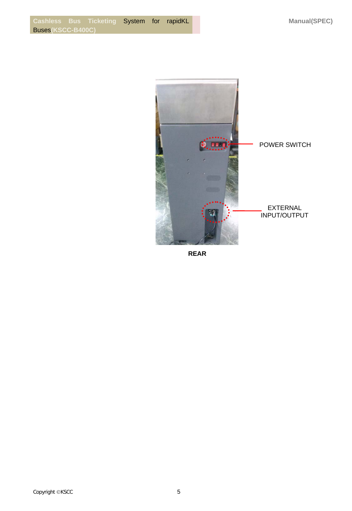
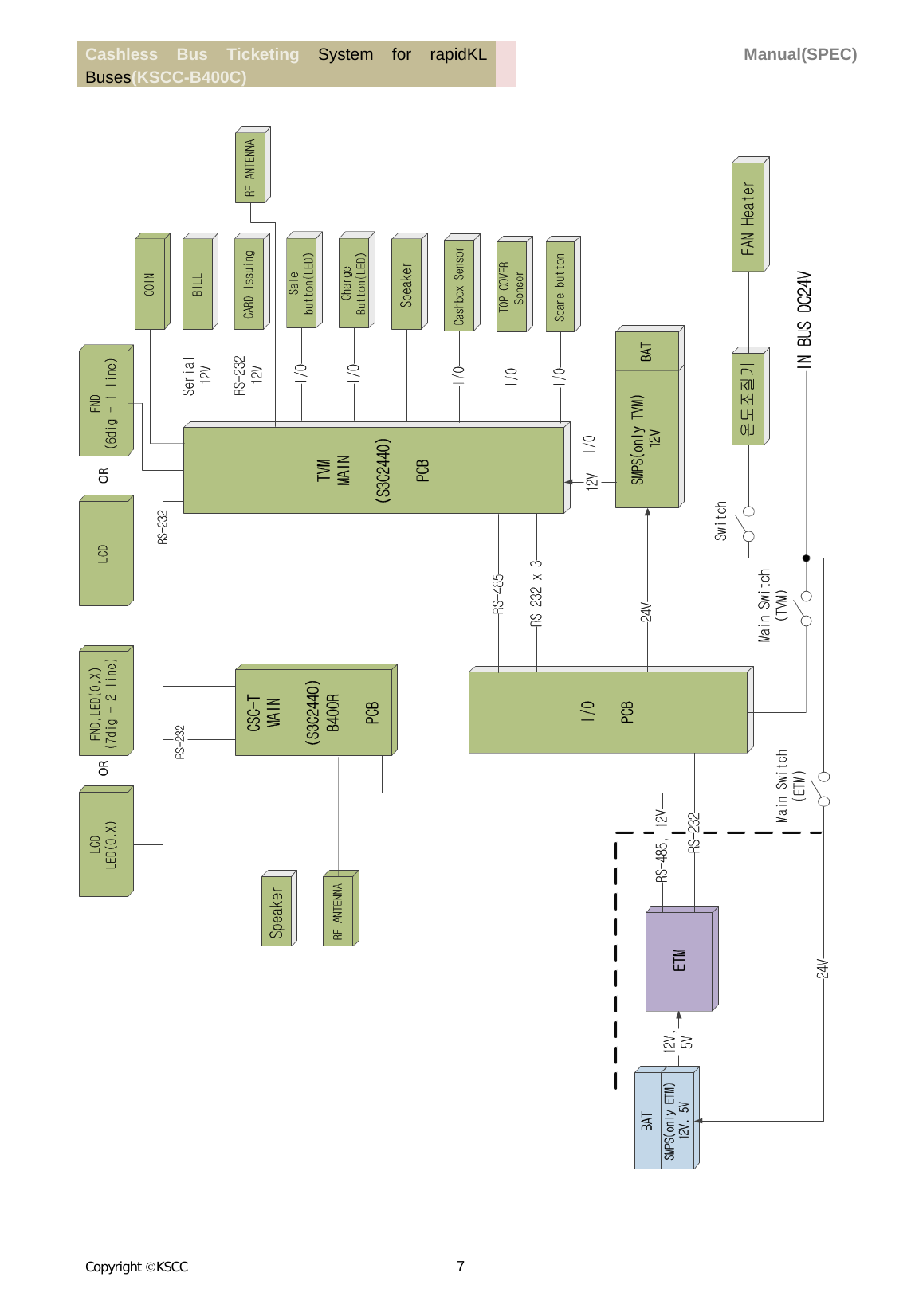
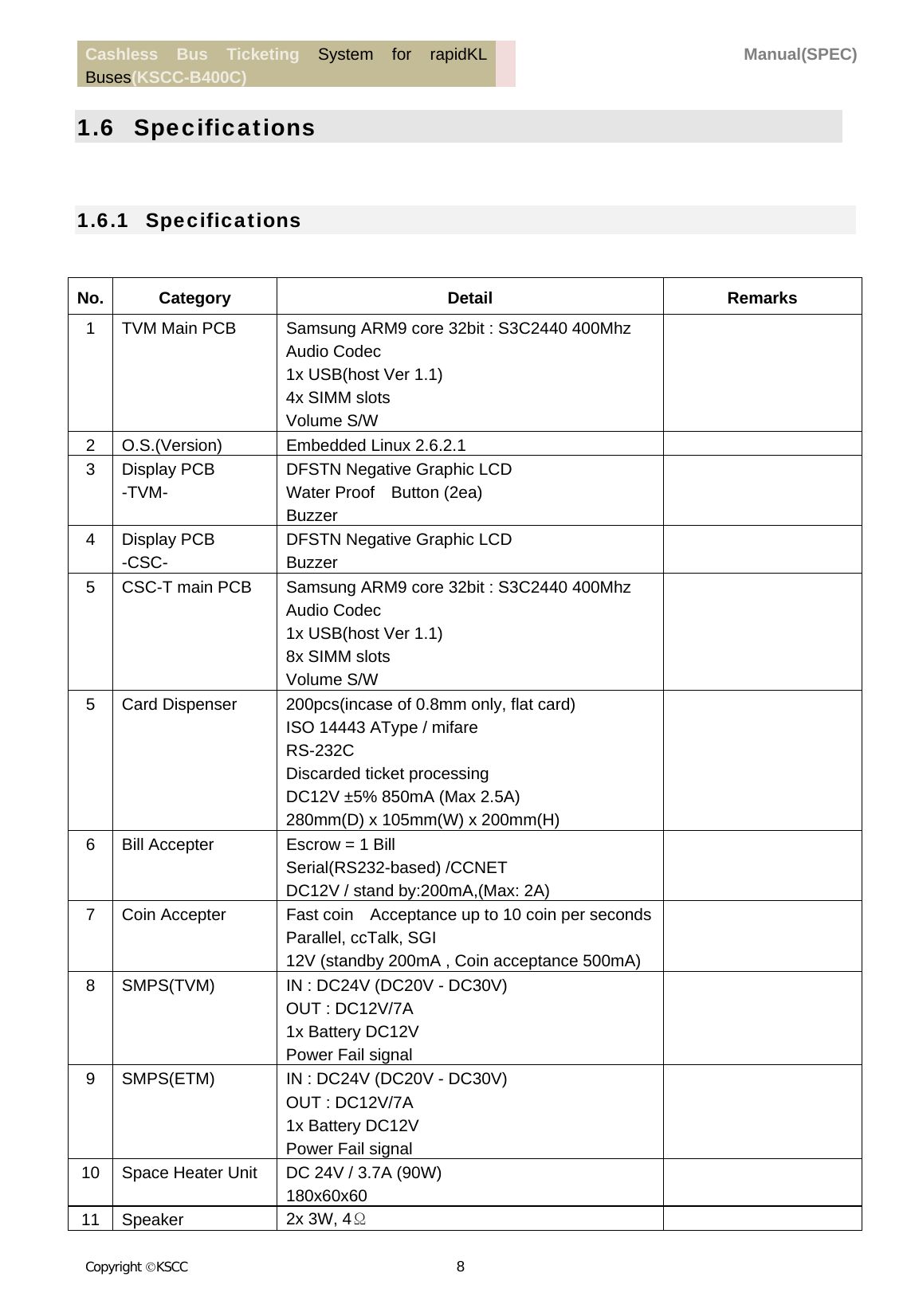
LG CNS KSCCB400C BUS TICKETING SYSTEM(RFID) User Manual

LG CNS CO., LTD. BUS TICKETING SYSTEM(RFID) Users Manual

Users Manual

Cashless Bus Ticketing System for rapidKL Buses(KSCC-B400C)  Manual(SPEC) Copyright KSCC 1    Bus Ticketing System(B400C)    Manual (TVM)  Ver 1.0                    Korea Smart Card Co., Ltd           This document is the property of Korea Smart Card Co., Ltd. and no part of this document   shall be copied or duplicated or given to other parties without written authorization
Cashless Bus Ticketing System for rapidKL Buses(KSCC-B400C)  Manual(SPEC) Copyright KSCC 2    Table of Contents  1. TVM ............................................................................................................................................. 3 1.1 Introduction ........................................................................................................................................ 3 1.2 Caution ................................................................................................................................................ 3 1.3 Tool & Equipment .............................................................................................................................. 3 1.4 Descriptions ......................................................................................................................................... 4 1.5 Block Diagram .................................................................................................................................... 6 1.6 Specifications ...................................................................................................................................... 7 1.7 Main Modules ................................................................................................................................. 111 1.7.1 Cash Box .................................................................................................................................................... 111 1.7.2 Switching Mode Power Supply (SMPS) .................................................................................................... 122 1.7.3 CARD DISPENSER .................................................................................................................................. 133 1.7.4 BILL Module ............................................................................................................................................... 14 1.7.5 COIN Module .............................................................................................................................................. 16 1.7.6 Space Heater ................................................................................................................................................ 17 1.7.7 Other ............................................................................................................................................................ 17
Cashless Bus Ticketing System for rapidKL Buses(KSCC-B400C)  Manual(SPEC) Copyright KSCC 3    1. TVM  1.1   Introduction This manual provides information on the use and the spec of the machine for the users.   1.2   Caution  1.  Please read the manual carefully for safe use.  2.  The machine must be kept in a cool area.  3.  Use the proper devices or tools to dissemble the machine to prevent damage.  4.  Be sure the power is off before dissembling the machine.  5.  BEWARE: electric shock or other safety related accidents.   1.3   Tool &Equipment    1. Screwdriver, WrenchDriver(M8), Hexagon Wrench Driver(M5), L-Wrench Driver(M6) , Torx WrenchDriver(M3)    2. USB (TVM version / CSC version)    3. SAM (TVM / CSC)
Cashless Bus Ticketing System for rapidKL Buses(KSCC-B400C)  Manual(SPEC) Copyright KSCC 4    1.4   Descriptions                                                                                DISPLAY BUTTON (BUY&CHARGE) CARD DISPENSER COIN SLOT BILL SLOT REFUND COIN DISPLAY CARD DISPENSER RFID ANTTENA CARD STACKER DISCARDED TICKET BOX SMPS (TVM/CSC) SMPS (TVM/CSC) CASH BOX COIN MODULE FRONT
Cashless Bus Ticketing System for rapidKL Buses(KSCC-B400C)  Manual(SPEC) Copyright KSCC 5                                                             POWER SWITCHEXTERNAL INPUT/OUTPUT REAR
Cashless Bus Ticketing System for rapidKL Buses(KSCC-B400C)  Manual(SPEC) Copyright KSCC 6      1.5   Block Diagram
Cashless Bus Ticketing System for rapidKL Buses(KSCC-B400C)  Manual(SPEC) Copyright KSCC 7
Cashless Bus Ticketing System for rapidKL Buses(KSCC-B400C)  Manual(SPEC) Copyright KSCC 8    1.6   Specifications  1.6.1   Specifications  No. Category  Detail  Remarks 1  TVM Main PCB  Samsung ARM9 core 32bit : S3C2440 400Mhz Audio Codec 1x USB(host Ver 1.1) 4x SIMM slots Volume S/W  2  O.S.(Version)  Embedded Linux 2.6.2.1   3 Display PCB -TVM- DFSTN Negative Graphic LCD Water Proof    Button (2ea) Buzzer  4 Display PCB  -CSC- DFSTN Negative Graphic LCD Buzzer  5  CSC-T main PCB  Samsung ARM9 core 32bit : S3C2440 400Mhz Audio Codec 1x USB(host Ver 1.1) 8x SIMM slots Volume S/W  5  Card Dispenser  200pcs(incase of 0.8mm only, flat card) ISO 14443 AType / mifare RS-232C Discarded ticket processing DC12V ±5% 850mA (Max 2.5A) 280mm(D) x 105mm(W) x 200mm(H)  6  Bill Accepter  Escrow = 1 Bill Serial(RS232-based) /CCNET DC12V / stand by:200mA,(Max: 2A)  7  Coin Accepter  Fast coin    Acceptance up to 10 coin per secondsParallel, ccTalk, SGI 12V (standby 200mA , Coin acceptance 500mA)  8  SMPS(TVM)  IN : DC24V (DC20V - DC30V) OUT : DC12V/7A 1x Battery DC12V Power Fail signal  9  SMPS(ETM)  IN : DC24V (DC20V - DC30V) OUT : DC12V/7A 1x Battery DC12V Power Fail signal  10  Space Heater Unit  DC 24V / 3.7A (90W) 180x60x60   11 Speaker  2x 3W, 4Ω
Cashless Bus Ticketing System for rapidKL Buses(KSCC-B400C)  Manual(SPEC) Copyright KSCC 9     1.6.2   Temperature Operating: 0℃ - +55℃ Humidity: 45% - 70%  1.6.3   Power Supply Requirements Supply Voltage: DC24V (DC20V - DC30V) Current Consumption Stand-by: 1.1A Operational: 1.7A (Max : 7A / Full load & Heater Unit)  1.6.4   Weight Base Unit: 50Kg
Cashless Bus Ticketing System for rapidKL Buses(KSCC-B400C)  Manual(SPEC) Copyright KSCC 10    1.6.5   Mating Connector 1. RS232-1          2. RS232-2          3. RS-485         4. ETM                         5. DC24V          Pin No.  Signal Description 1 DC12V(OUT) 2 UART_TX 3 UART_RX 4 GND 5 NC Pin No.  Signal Description 1 DC12V(OUT) 2 UART_TX 3 UART_RX 4 GND 5 NC Pin No.  Signal Description 1 DC12V(OUT) 2 TVM 485+ 3 TVM 485- 4 GND Pin No.  Signal Description 1 DC12V(OUT) 2 DC5V(OUT) 3 UART_TX 4 UART_RX 5 ETM_12V 6 CSC 485+ 7 CSC 485- 8 GND Pin No.  Signal Description 1 DC24V(OUT) 2 GND 3 EARTH
Cashless Bus Ticketing System for rapidKL Buses(KSCC-B400C)  Manual(SPEC) Copyright KSCC 11     1.6.6   TVM, CSC-T main PCB Names                    LED Indicator                     TVM LEDTVM DIP SwitchTVM Volume Switch(UP, DOWN)TVM USBTVM DebugCSC-T Debug CSC-T LEDCSC-T DIP Switch TVM  CSC-T
Cashless Bus Ticketing System for rapidKL Buses(KSCC-B400C)  Manual(SPEC) Copyright KSCC 12     1.7   Main Modules  1.7.1   Cash Box  Specifications  Size: 183mm(w) x 201mm(h) x 230mm(d)  Capacity: 400 (Free fall type)  Material: Stainless Steel  Key lock  3Keys  Caution: Be sure not to lose or misplace your cashbox key. The cashbox may be damaged at shock or drop. Be sure to understand the manual before installing   or removing the cashbox (refer to Cashbox Installation and Removal).
Cashless Bus Ticketing System for rapidKL Buses(KSCC-B400C)  Manual(SPEC) Copyright KSCC 13     1.7.2   Switching Mode Power Supply (SMPS)  Specifications  No. Function  TVM  ETM 1  Power IN  DC24V (DC20V - DC30V)  DC24V (DC20V - DC30V) 2 Power OUT  DC12V/7A  DC12V/7A 3 Battery #2  1x DC12V  1x DC12V 4 LED(Green)  O  O 5 FUSE  10A  10A 6  Power Fail signal  O  O 7 Protection  Over Current Over Voltage Over Current Over Voltage  #1.Do not share the power for TVM and ETM; make sure they are plugged in separately. #2.When the input power is shut off, UPS kicks in by the backup battery.With the fully charged battery, the system will be powered for about 5 minutes (However, it may be shorter depending on the battery life or obsolete battery). To prevent any damage or significantly lowered battery life from over-discharge, the battery output power is automatically cut off when the power is not supplied within a certain period of time after the input power is shut off. #3.Be sure that the battery case is not worn off to facilitate the battery installation and removal.                TVM  ETMPower out LED FUSEIN/OUT Connector
Cashless Bus Ticketing System for rapidKL Buses(KSCC-B400C)  Manual(SPEC) Copyright KSCC 14     1.7.3   CARD DISPENSER  Specifications 1.  Card Type  ISO 14443    A Type / Mifare 2  Card Stack Capability  200pcs (incase of 0.8mm only, flat card) 3  Function  Discarded ticket processing 4 Interface RS-232C 5  Power  DC12V ±5% 850mA (Max 2.5A) 6  Size  280mm (D) x 105mm (W) x 200mm (H)   Pin Connections  Pin Number  Signal Description  Note 1 DC12V   2 RS232 TX   3 RS232 RX   4 GND   5 GND   6 NC   7 NC   8 NC   9 NC             1  2  3  4  56  7  8  9PC SUB-9pin (male)
Cashless Bus Ticketing System for rapidKL Buses(KSCC-B400C)  Manual(SPEC) Copyright KSCC 15     1.7.4   BILLMODULE               Specifications 1  Acceptable CashCode Length: 92.5 mm   Width: 132 mm HeIght : 100.6 mm 2  Insertion Direction 4-way 3  Validation Method Optical/Transparency/Reflection/MAG 4  Interface Serial 5 Escrow  1 banknote 6 LED  LED lamp (upper position of faceplate) Full-color lightning (gradation/solid) 7  Power Supply Voltage 12V DC ±5 % 8  Rated Power Consumption Standby: Approx. 0.1 A Operation: Approx. 0.8 A Max: Approx. 1.4 A (Max. 300 ms)  Connector  The following diagram is the interface connector as viewed from the acceptor side or from a relay board.   1) Power Connector
Cashless Bus Ticketing System for rapidKL Buses(KSCC-B400C)  Manual(SPEC) Copyright KSCC 16                2) Data Connector                        DIP Switch Settings
Cashless Bus Ticketing System for rapidKL Buses(KSCC-B400C)  Manual(SPEC) Copyright KSCC 17      The switches are located at the CPU board.   The VU(MVU) bill Validator operates in two basic modes: Validation Mode and Service Mode.   Validation Mode: This is the mode for normal operation.   Service Mode: This is the mode for programming and testing.   A set of 8 DIP switches (SW1) defines the settings and programs the Bill Validator to recognize and validate different denominations or define other parameters.      A set of 4 DIP switches (SW1) defines the settings of interface type.   For a complete explanation of switch description, please see the software User’s Guide (enclosed to each bill validator and available at www.cashcode.com).
Cashless Bus Ticketing System for rapidKL Buses(KSCC-B400C)  Manual(SPEC) Copyright KSCC 18         1.7.5   COIN MODULE Specifications 1  Function  Fast coin    Acceptance up to 10 coin per seconds 2  Interface  Parallel, ccTalk, SGI 3  Power  12V (standby 200mA , Coin acceptance 500mA) 4  Operating range  0°C to 60°C ,   5  Coin acceptance  32 coin types max. in 2 x 16 or 1 x 32 channels Coin diameter:15–32.5mm Coin thickness:1.5–3.3mm Speed:10 coins/sec. 6  Mounting position  Vertical, max. deviation: ± 2° 7  Size  102mm (D) x 89mm (W) x 52mm (H) 8  Mark of conformity  CE
Cashless Bus Ticketing System for rapidKL Buses(KSCC-B400C)  Manual(SPEC) Copyright KSCC 19     Connector
Cashless Bus Ticketing System for rapidKL Buses(KSCC-B400C)  Manual(SPEC) Copyright KSCC 20         1.7.6   Space heater Specifications 1 Function Space Heating 3  Power  24V / 3.7A (90W) 4  Operating range  Analog SW : -20°C to 50°C , 5  Serface Temp  Arround : 23°C , End of    heater 50°C ,
Cashless Bus Ticketing System for rapidKL Buses(KSCC-B400C)  Manual(SPEC) Copyright KSCC 21    1.7.7   Others  Power S/W    GENERAL (Subpart A) Any changes or modifications to the equipment not expressly approved by the party responsible for compliance could void the user's authority to operate the equipment.    UNINTENTIONAL RADIATORS (Part15, Subpart B, 15.105) Note: This equipment has been tested and found to comply with the limits for a Class B digital device, pursuant to part 15 of the FCC Rules. These limits are designed to provide reasonable protection against harmful interference in a residential installation.   This equipment generates, uses and can radiate radio frequency energy and, if not installed and used in accordance with the instructions, may cause harmful interference to radio communications. However, there is no guarantee that interference will not occur in a particular installation. If this equipment does cause harmful interference to radio or television reception, which can be determined by turning the equipment off and on, the user is encouraged to try to correct the interference by one or more of the following measures: ①  Reorient or relocate the receiving antenna. ②  Increase the separation between the equipment and receiver. ③  Connect the equipment into an outlet on a circuit different from that to which the receiver is connected. ④  Consult the dealer or an experienced radio/TV technician for help.  FCC Statement
Cashless Bus Ticketing System for rapidKL Buses(KSCC-B400C)  Manual(SPEC) Copyright KSCC 22     This device complies with Part 15 of the FCC Rules. Operation is subject to the following two conditions: (1) This device may not cause harmful interference. and   (2) This device must accept any interference received, including interference that may cause undesired operation.  Any changes or modifications (including the antenna) made to this device that are not expressly approved by the manufacturer may void the user’s authority to operate the equipment.   This equipment has been tested and found to comply with the limits for a Class B digital device, pursuant to part 15 of the FCC Rules. These limits are designed to provide reasonable protection against harmful interference in a residential installation.   This equipment generates uses and can radiate radio frequency energy and, if not installed and used in accordance with the instructions, may cause harmful interference to radio communications. However, there is no guarantee that interference will not occur in a particular installation. If this equipment does cause harmful interference to radio or television reception, which can be determined by turning the equipment off and on, the user is encouraged to try to correct the interference by one or more of the following measures:   - Reorient or relocate the receiving antenna.   - Increase the separation between the equipment and receiver.   - Connect the equipment into an outlet on a circuit different from that to which the receiver is connected.  - Consult the dealer or an experienced radio/TV technician for help.

Navigation menu