LG CNS KSCCCBB450R VALIDATOR User Manual KSCC CB B450R
LG CNS CO., LTD. VALIDATOR KSCC CB B450R
LG CNS >
Users Manual
Sistema de Recaudo Control e Información y
Servicio al Usuario Proyect
Maintenance and Repair Manual
(Heavy)
Equipment Name
CB-EVA-HM-00-V1.0
Copyright LG CNSⓒ
It is forbidden to copy and distribute on certain or whole part of this content without precedent approval of LG CNS

Bogota SIRCI Project
Maintenance and Repair Manual (Heavy)
CB-EVA-HM-00-V1.0 Zonal Validator Page i of All
Document Prepared by: Reviewed by: Approved by:
Maintenance and
Repair Manual (Heavy)

Bogota SIRCI Project
Maintenance and Repair Manual (Heavy)
CB-EVA-HM-00-V1.0 Zonal Validator Page ii of All
Document History
Previous
Version
Present
Document
Date Numeral Changes Type

Bogota SIRCI Project
Maintenance and Repair Manual (Heavy)
CB-EVA-HM-00-V1.0 Zonal Validator Page iii of All
Table Of Contents
1. VALIDATOR STRUCTURE
................................
................................................................
...............................................
..............................
...............
1
11
1
1.1 Outline
................................
................................................................
..............................................................
............................................................
..............................
1
11
1
1.2 External/Internal structure and main module
............................
........................................................
............................
1
11
1
1.2.1 External structure ................................................... 1
1.2.2 Main module structure I .............................................. 2
1.2.3 Internal structure .................................................... 3
1.2.4 Main module structure ............................................... 4
2. ERROR HANDLING
2. ERROR HANDLING2. ERROR HANDLING
2. ERROR HANDLING
................................
................................................................
.........................................................
..................................................
.........................
5
55
5
2.1.1 Supply the power (1/2) ............................................ 5
2.1.2 Supply the power (2/2) ............................................ 6
2.1.3 USB Trouble (1/2) ................................................. 7
2.1.4 USB Trouble (2/2) ................................................. 8
2.1.5 RTC Trouble (1/2) ................................................. 9
2.1.6 RTC Trouble (2/2) ............................................... 10
3. DEVICE MAINTENANC
3. DEVICE MAINTENANC3. DEVICE MAINTENANC
3. DEVICE MAINTENANCE
EE
E
................................
................................................................
...................................................
......................................
...................
11
1111
11
3.1 Main Board
3.1 Main Board3.1 Main Board
3.1 Main Board
................................
................................................................
.........................................................
..................................................
.........................
11
1111
11
3.1.1 Outline ......................................................... 11
3.1.2 Structure ....................................................... 11
3.1.3 Spec ............................................................ 12
3.1.4 Replacement method .............................................. 14
3.2 Maintenance Flow chart
3.2 Maintenance Flow chart3.2 Maintenance Flow chart
3.2 Maintenance Flow chart
................................
................................................................
.............................................
..........................
.............
17
1717
17
4. VALIDATOR INSTALL
4. VALIDATOR INSTALL4. VALIDATOR INSTALL
4. VALIDATOR INSTALLATION AND UPDATE
ATION AND UPDATEATION AND UPDATE
ATION AND UPDATE
................................
................................................................
....................................
........
....
18
1818
18
4.1 Validator installation
4.1 Validator installation4.1 Validator installation
4.1 Validator installation
................................
................................................................
.............................................
..........................
.............
18
1818
18
4.1.1 Process ......................................................... 18
4.1.2 Device registration ............................................. 18
Bogota SIRCI Project
User Requirement Definition
CB-EVA-HM-00-V1.0 Zonal Validator Page
1
11
1
of All
1. Validator structure
1.1 Outline
Validator is the device that recognize bus passenger’s card.
1.2 External/Internal structure and main module
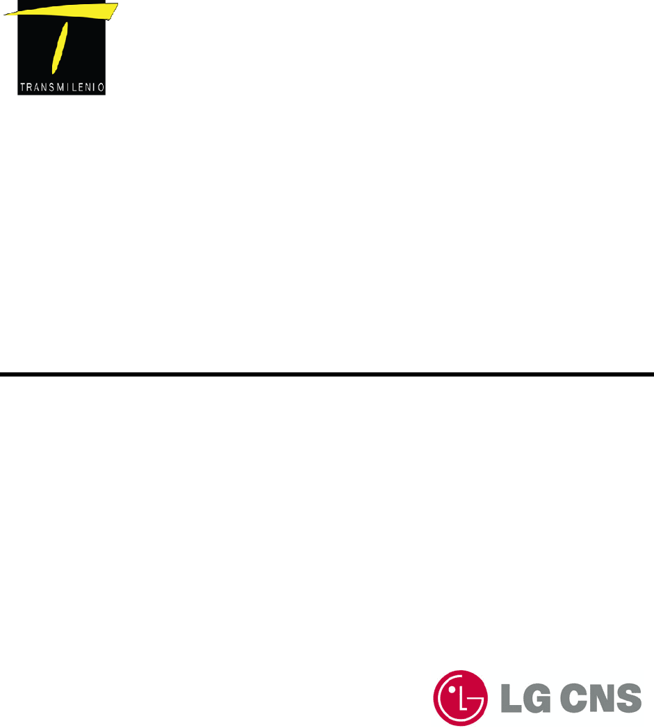
1.2.1 External structure
Division Contents
Size 210mm(W) x 210m(H) x 65mm(D)
Material Aluminum + SPCC
210
210210
210mm
mmmm
mm(W)
(W)(W)
(W)
210
210210
210mm
mmmm
mm(W)
(W)(W)
(W)
Bogota SIRCI Project
User Requirement Definition
CB-EVA-HM-00-V1.0 Zonal Validator Page
2
22
2
of All
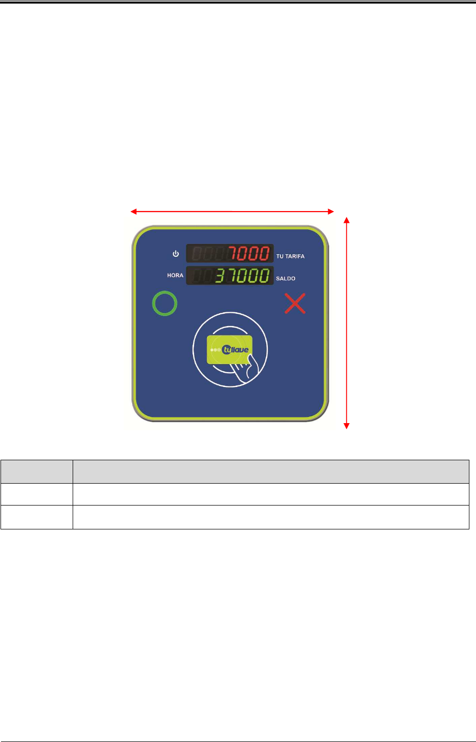
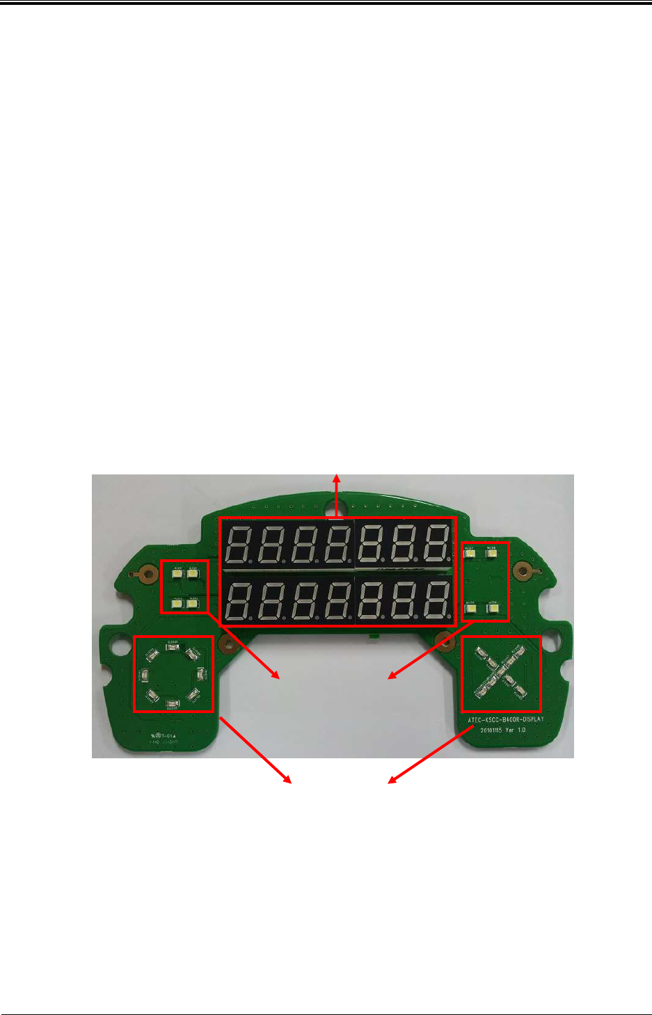
1.2.2 Main module structure I
Validator
Name Explanation
1) 7 Segment FND
(3DIGIT + 4DIGIT) Display the deducted amount of card
2)7 Segment FND
(3DIGIT + 4DIGIT) Display the after deducted amount of card
3) O, X LED Determine whether the card is recognized
4) RFID Antenna ISO14443 Type A/B, 13.56MHz recognize the Card and
recharge.
210
210210
210m
mm
mm
mm
m(H)
(H)(H)
(H)
210
210210
210mm
mmmm
mm(W)
(W)(W)
(W)
1
)
3
)
3
)
4
)
2
)
Bogota SIRCI Project
User Requirement Definition
CB-EVA-HM-00-V1.0 Zonal Validator Page
3
33
3
of All
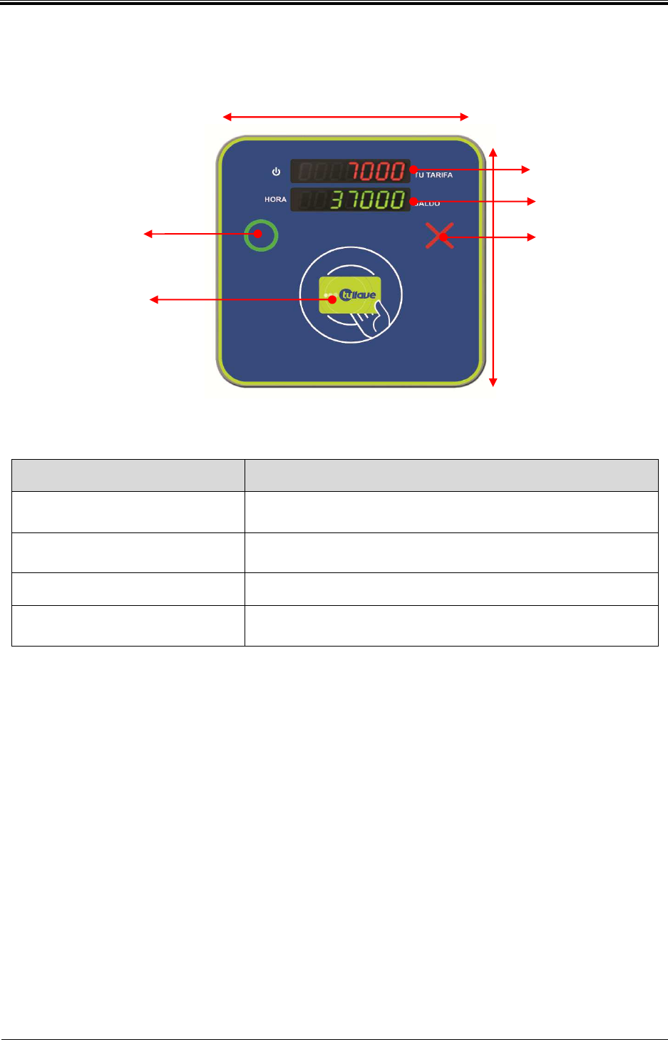
1.2.3 Internal structure
M
ain Board
Main Board
Display
Board
Antenna Board

Bogota SIRCI Project
User Requirement Definition
CB-EVA-HM-00-V1.0 Zonal Validator Page
4
44
4
of All
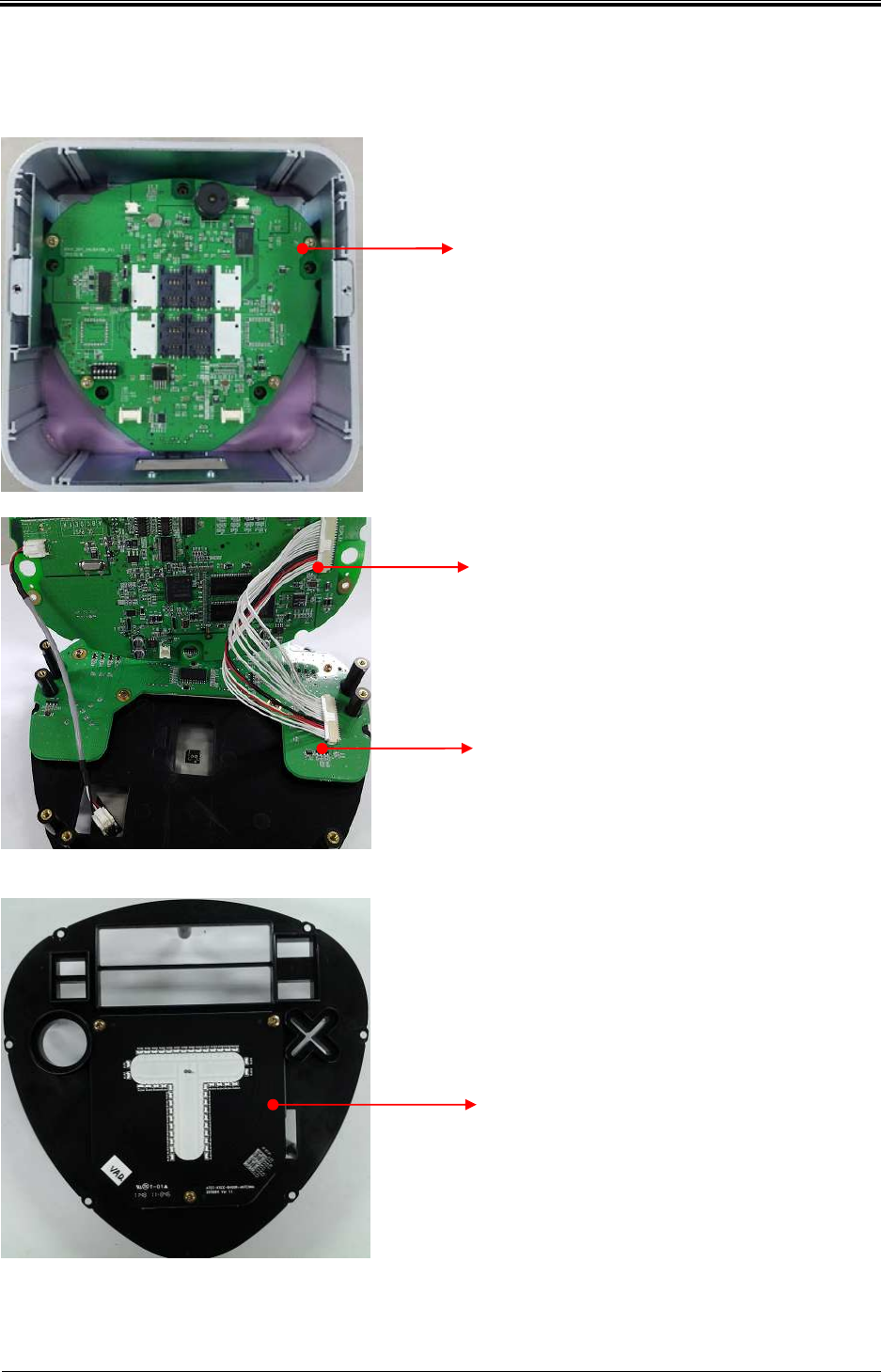
1.2.4 Main module structure
1) 7 Segment FND(3DIGIT + 4DIGIT)
Display deducted amount of card and after deducted amount of card.
2) O, X LED
Check card recognition
3) RFID Antenna
RF interface for reading 13.56MHz RF Card
4) Main Board
Control all parts of Validator, transfer processed information of each accessory to Main ser
ver.
CPU
- S3C2440(ARM9 Core) : 400MHz
Memory
- SDRAM : 128MByte
- Nor : 8MByte
- Nand : 512Myte
RF Module
- RC531( Type A,B)
External PORT
- Ethernet : 1EA
- USB1.1 : 1EA
- RS -232 : 1EA
SAM
- Socket 4EA(SIM Type)
5) Display Board
Communicate with Main Board and control Display(7 Segment FND + Backlight LED).
Bogota SIRCI Project
User Requirement Definition
CB-EVA-HM-00-V1.0 Zonal Validator Page
5
55
5
of All
2. Error handling
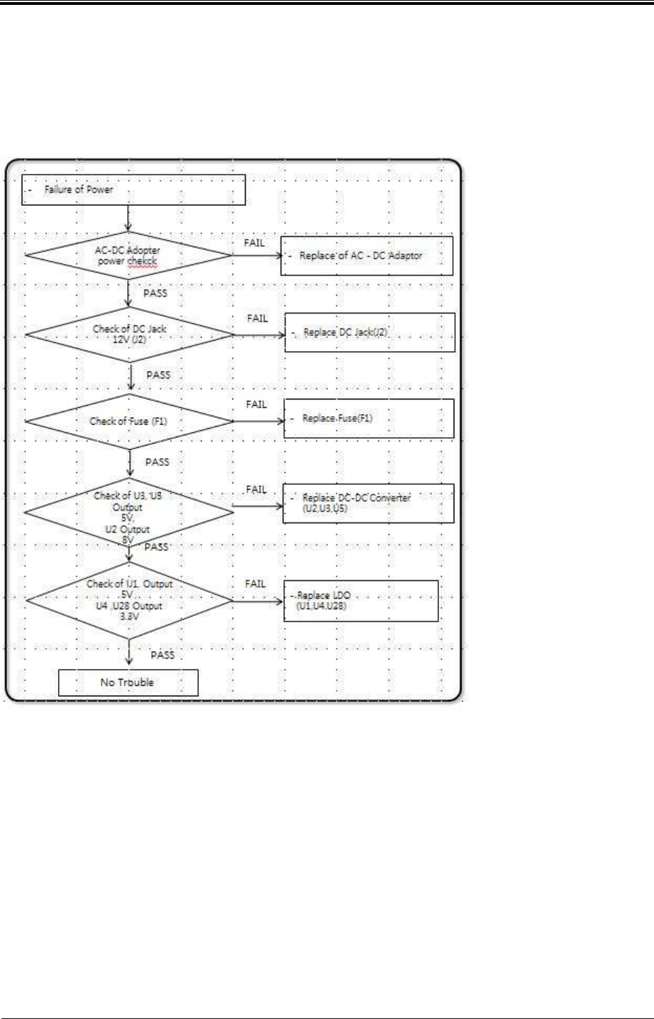
2.1.1 Supply the power (1/2)
Bogota SIRCI Project
User Requirement Definition
CB-EVA-HM-00-V1.0 Zonal Validator Page
6
66
6
of All
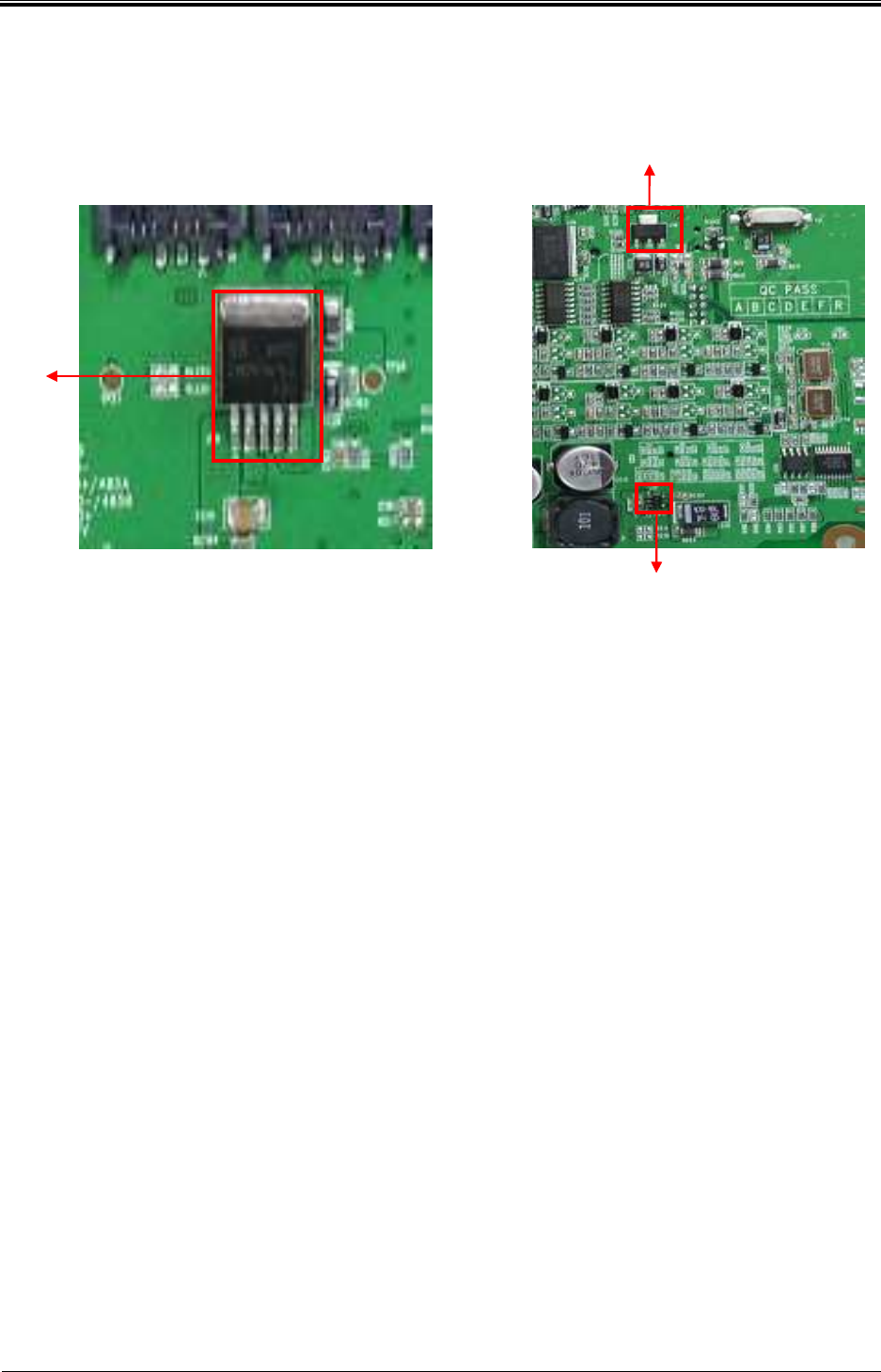
2.1.2 Supply the power (2/2)
Check U18 Output
5V
Check U14 Output
1.3V
Check U17 Output
3.3V
Bogota SIRCI Project
User Requirement Definition
CB-EVA-HM-00-V1.0 Zonal Validator Page
7
77
7
of All
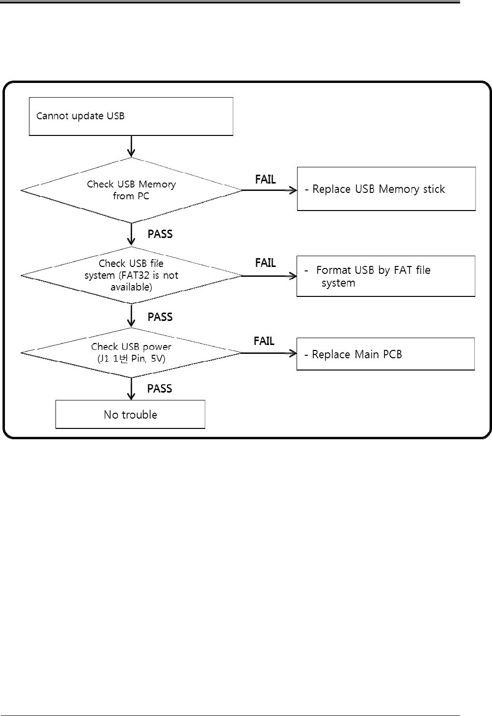
2.1.3 USB Trouble (1/2)
Bogota SIRCI Project
User Requirement Definition
CB-EVA-HM-00-V1.0 Zonal Validator Page
8
88
8
of All
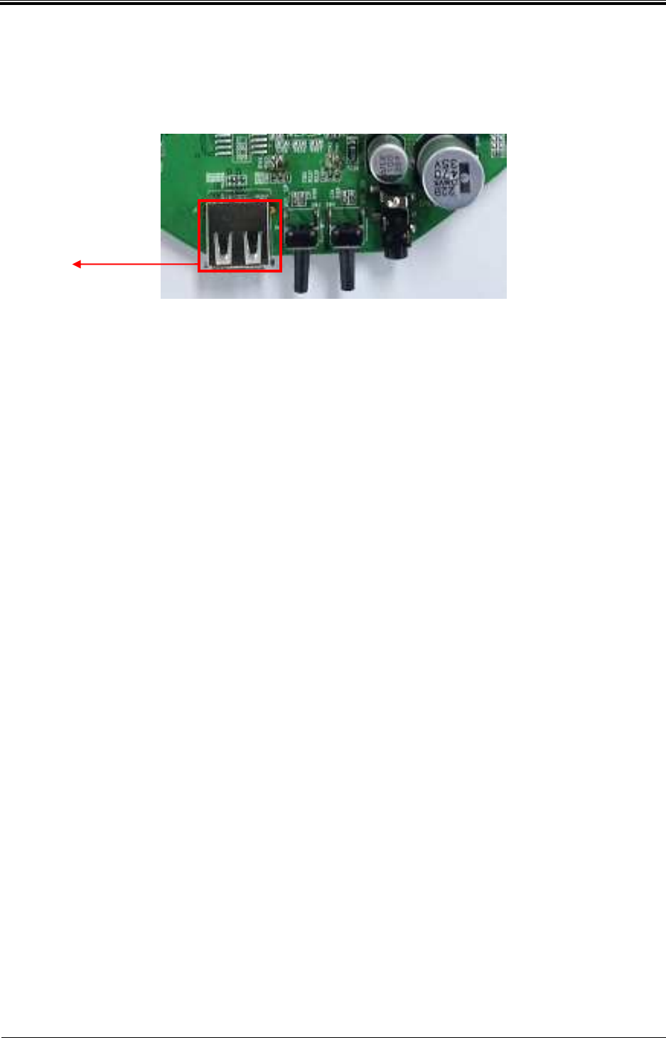
2.1.4 USB Trouble (2/2)
Check U1 Output
Pin No. 1 5Votage
Bogota SIRCI Project
User Requirement Definition
CB-EVA-HM-00-V1.0 Zonal Validator Page
9
99
9
of All
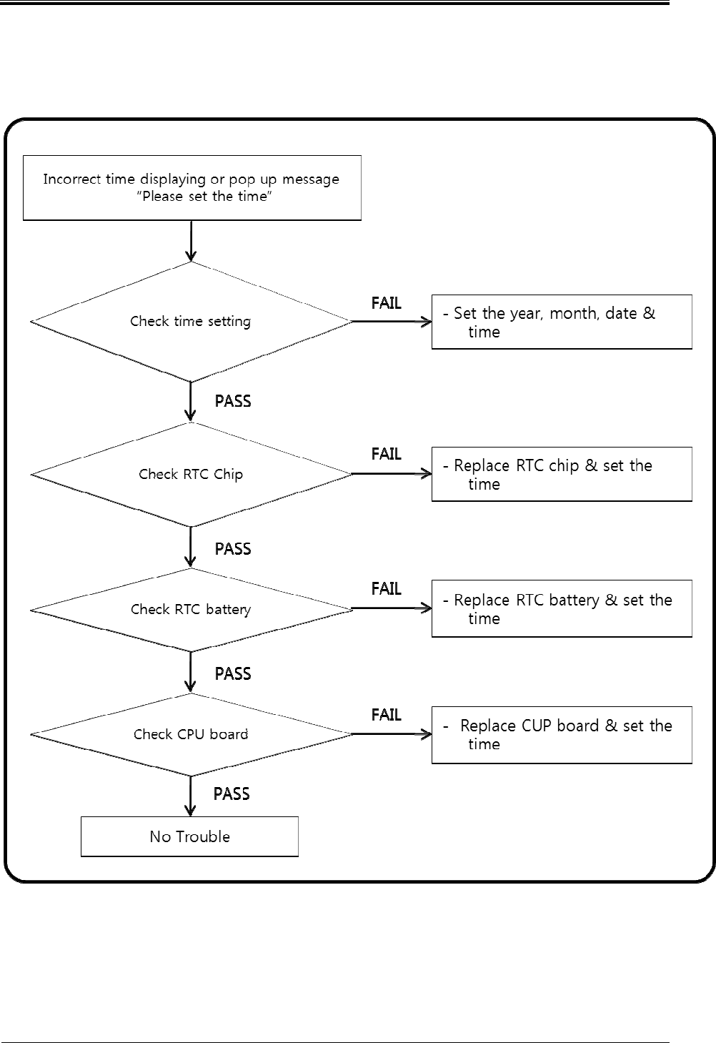
2.1.5 RTC Trouble (1/2)
Bogota SIRCI Project
User Requirement Definition
CB-EVA-HM-00-V1.0 Zonal Validator Page
10
1010
10
of All
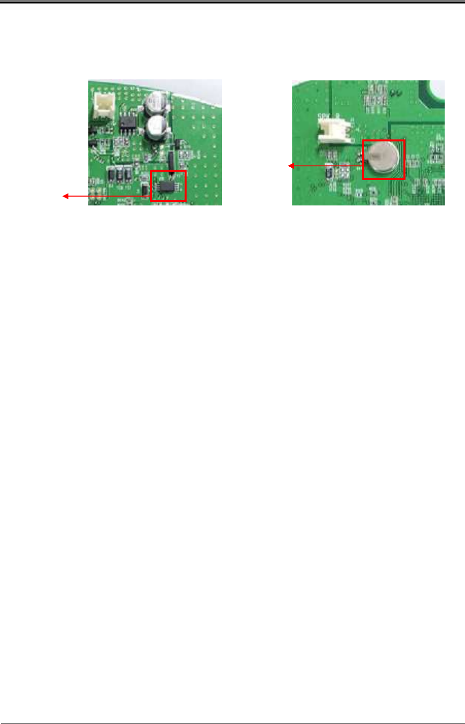
2.1.6 RTC Trouble (2/2)
Check U15 Reset
IC
Check
BAT1 Reset
battery
Bogota SIRCI Project
User Requirement Definition
CB-EVA-HM-00-V1.0 Zonal Validator Page
11
1111
11
of All
3. Device maintenance
3.1 Main Board
3.1.1 Outline
Control all parts of Validator, transfer processed information of each accessory to Main server.
3.1.2 Structure
M
ain Boa
rd
Main Board
Display
Board
Antenna Board
Bogota SIRCI Project
User Requirement Definition
CB-EVA-HM-00-V1.0 Zonal Validator Page
12
1212
12
of All
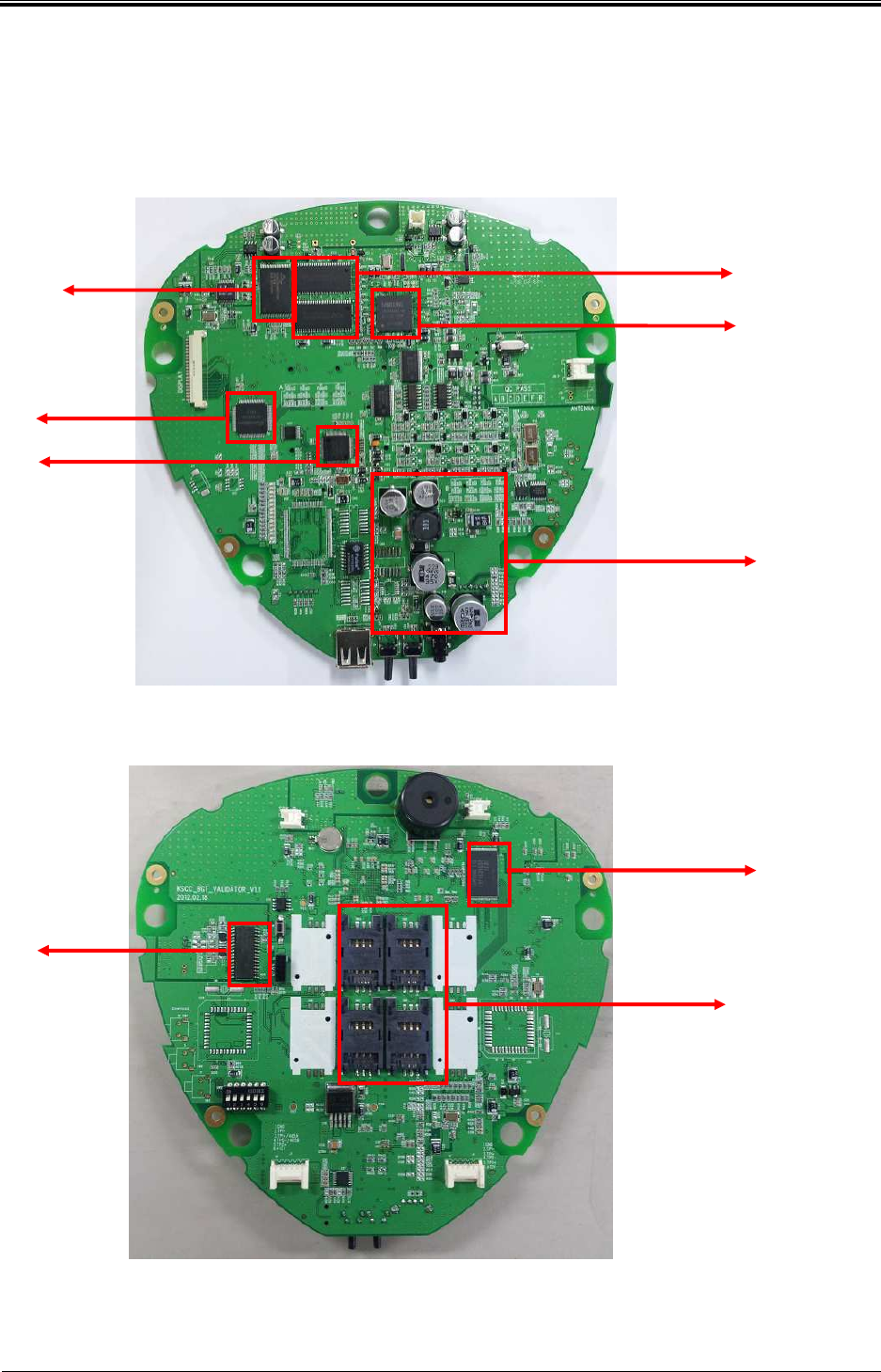
3.1.3 Spec
1) Main Board Spec
S3C2440
RC531
POWER Part
NOR FLASH
EXT UART
ETHERNET
NAND FLASH
RC531
SIM SLOT
Bogota SIRCI Project
User Requirement Definition
CB-EVA-HM-00-V1.0 Zonal Validator Page
13
1313
13
of All
Control all parts of Validator, transfer processed information of each accessory to Main ser
ver.
CPU
- S3C2440(ARM9 Core) : 400MHz
Memory
- SDRAM : 128MByte
- Nor : 8MByte
- Nand : 512Myte
RF Module
- RC531( Type A,B)
External PORT
- Ethernet : 1EA
- USB1.1 : 1EA
- RS -232 : 1EA
SAM
- Socket 4EA(SIM Type)
2) Display Board Spec
7 Segment FND
O, X LED
Backlight LED
Bogota SIRCI Project
User Requirement Definition
CB-EVA-HM-00-V1.0 Zonal Validator Page
14
1414
14
of All
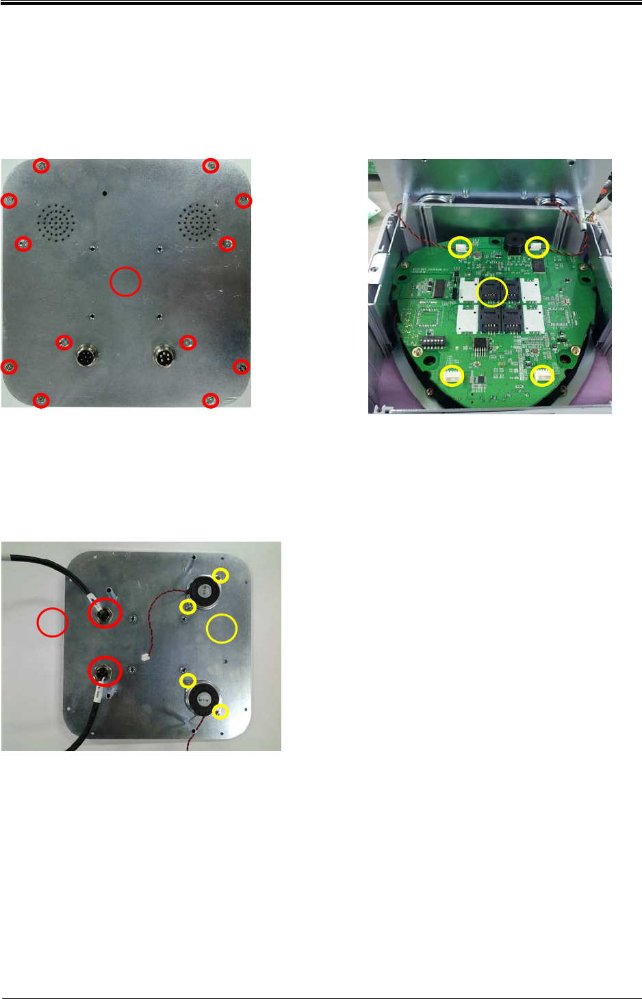
3.1.4 Replacement method
3.1.4.1 Separation back cover
① Loosen fixed 12 bolts and separate cover.
② Remove the cover and 4 inside connector and separate back cover completely.
3.1.4.2 Cable separation
① Loosen the hex nut to separate circular
connector
② Loosen the 4 hex nuts to separate
speaker.
1
11
1
2
22
2
1
11
1
2
22
2
Bogota SIRCI Project
User Requirement Definition
CB-EVA-HM-00-V1.0 Zonal Validator Page
15
1515
15
of All
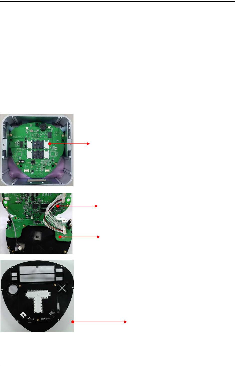
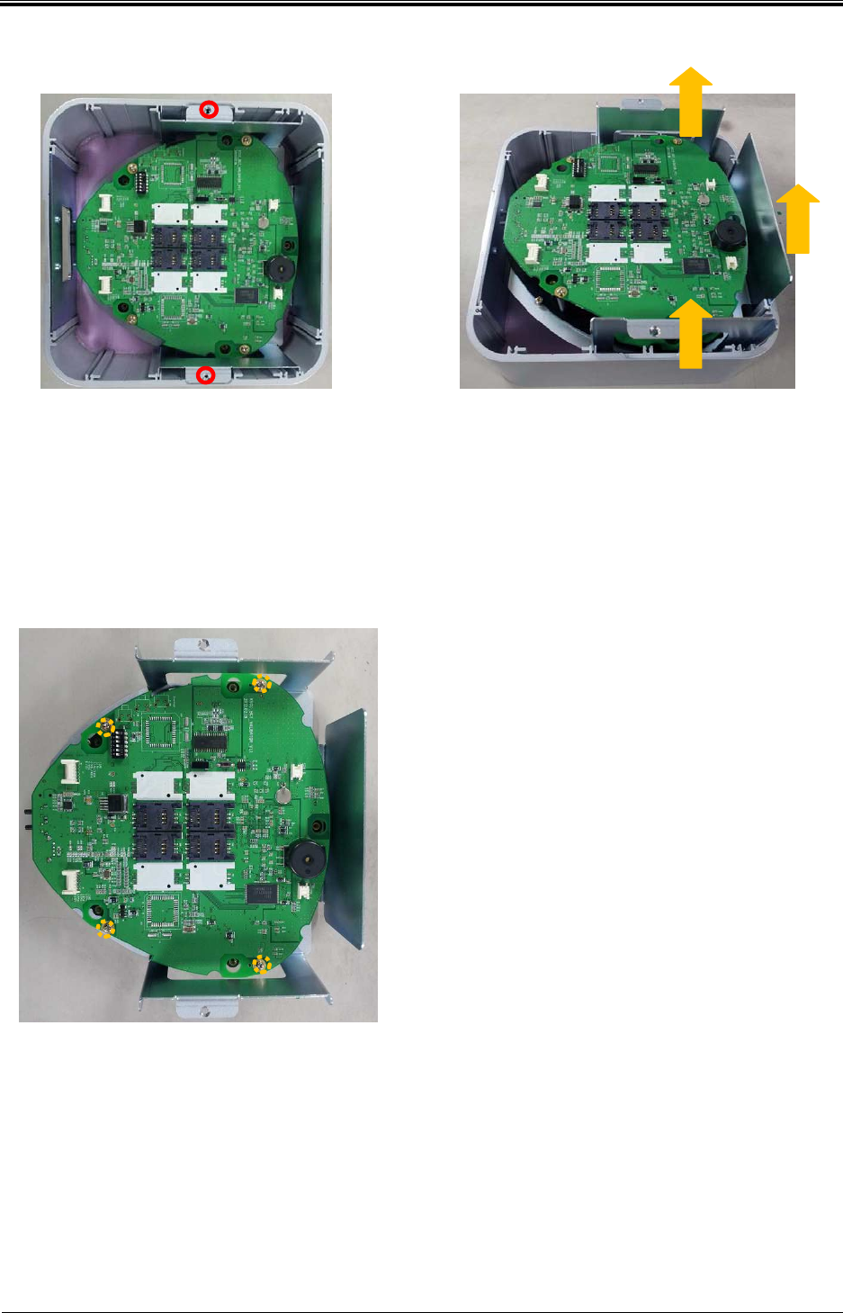
3.1.4.3 Separate external enclosure and internal Bracket.
① Loosen 2 fixed bolts of each sides and lift PCB fixed Bracket in the
direction of the arrow in the picture.
3.1.4.4 Separate inside Bracket and PCB Bracket
① Loosen fixed 4 bolts and push Bracket
slightly and separate board.
Bogota SIRCI Project
User Requirement Definition
CB-EVA-HM-00-V1.0 Zonal Validator Page
16
1616
16
of All
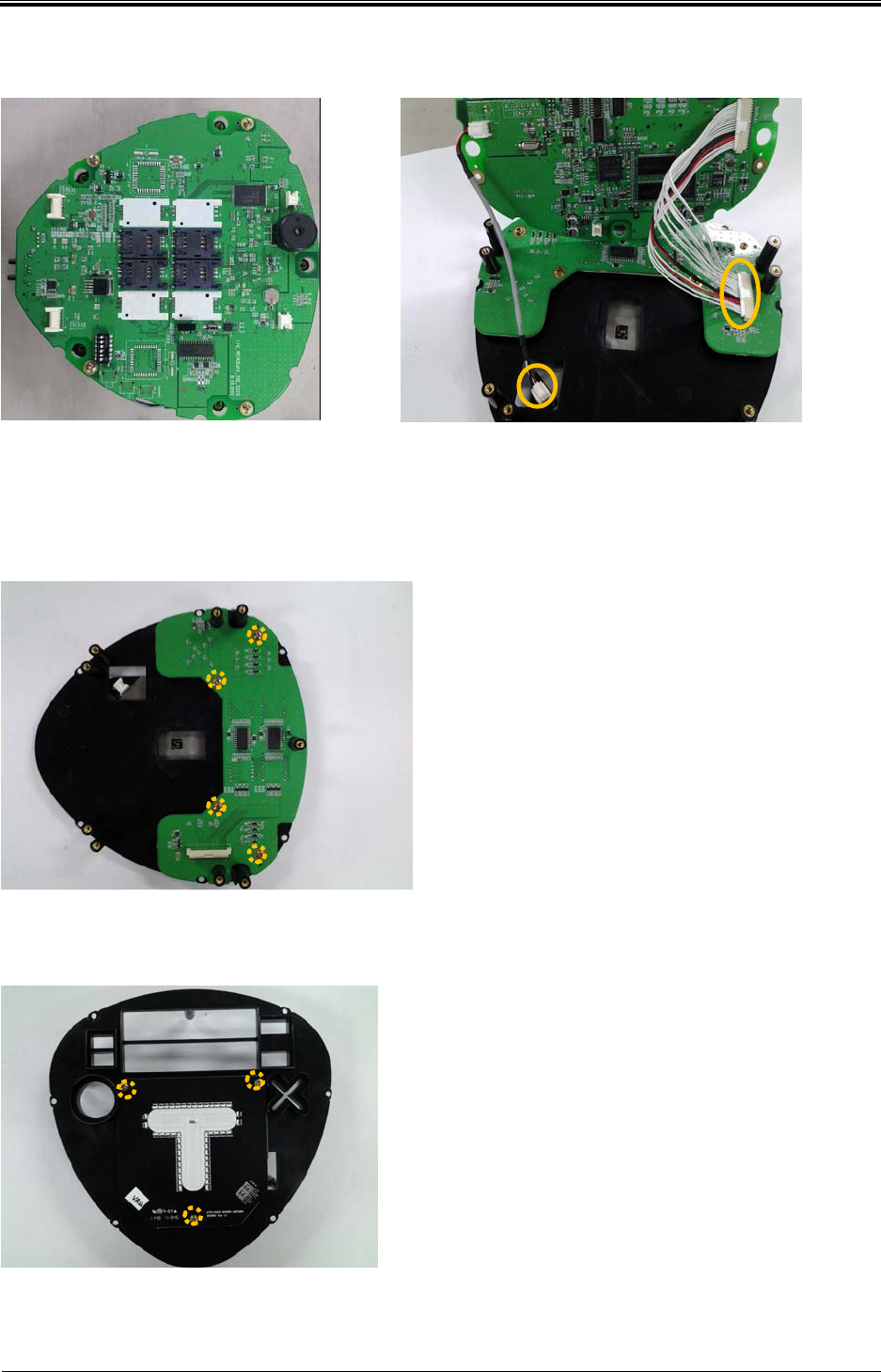
3.1.4.5 Separate PCB Bracket and Main PCB
① Loosen 4 fixed bolts and pick up the board, separate connectors as
shown to the right picture and separate the board completely.
3.1.4.6 Separate PCB Bracket and Display
① Loosen 4 fixed bolts and
separate display board.
3.1.4.7 Separate Antenna board
① Loosen 3 fixed bolts and
separate antenna board.
Bogota SIRCI Project
User Requirement Definition
CB-EVA-HM-00-V1.0 Zonal Validator Page
17
1717
17
of All
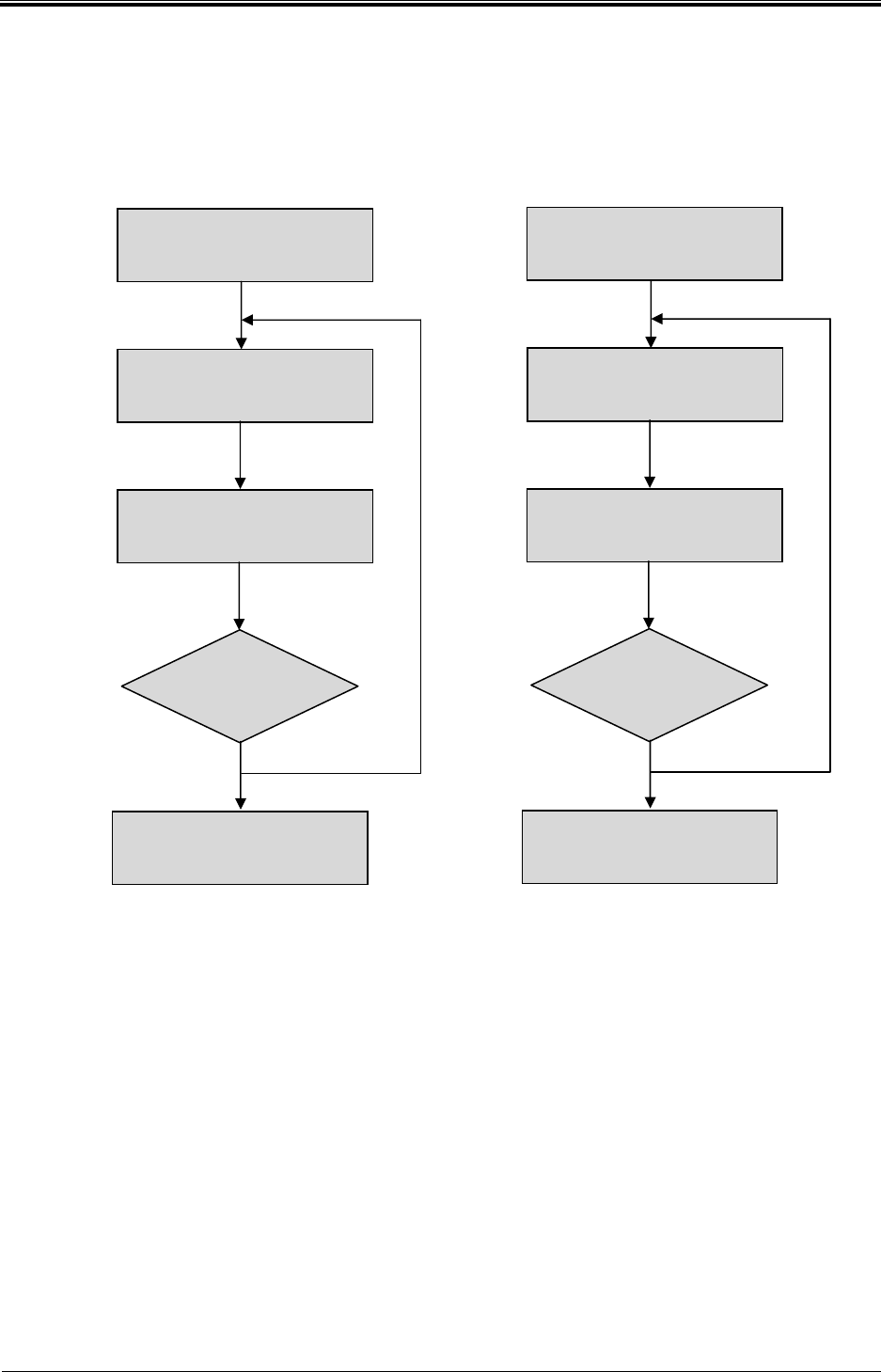
3.2 Maintenance Flow chart
1) Required tool: Driver, tester, etc.
2) Precautions
- Check each part of the adjustment value for every 12months or in a timely
manner.
Conduct
TEST
Error
Check ERROR CODE
Dev
ice maintenance
and replacement due to
MANUAL
Repair complete
OK
NO
Conduct
TEST
Receive replacement
parts
Check maintenance
referral and ERROR CODE
Device repair due to
MANUAL
Repair complete
OK
NO
Bogota SIRCI Project
User Requirement Definition
CB-EVA-HM-00-V1.0 Zonal Validator Page
18
1818
18
of All
3) Detail check items
No Items
Inspection cycle
Note
1 month
3months
6months
12months
1
Power/Voltage Check
2 Check LCD operation
3 Check O,XLED operation
4. Validator installation and update
4.1 Validator installation
4.1.1 Process
No
Division
C
ontents
N
ote
1
Device
registration
1) USB
mounting method
2) SAM mounting
3)
Power
ON
… … … …
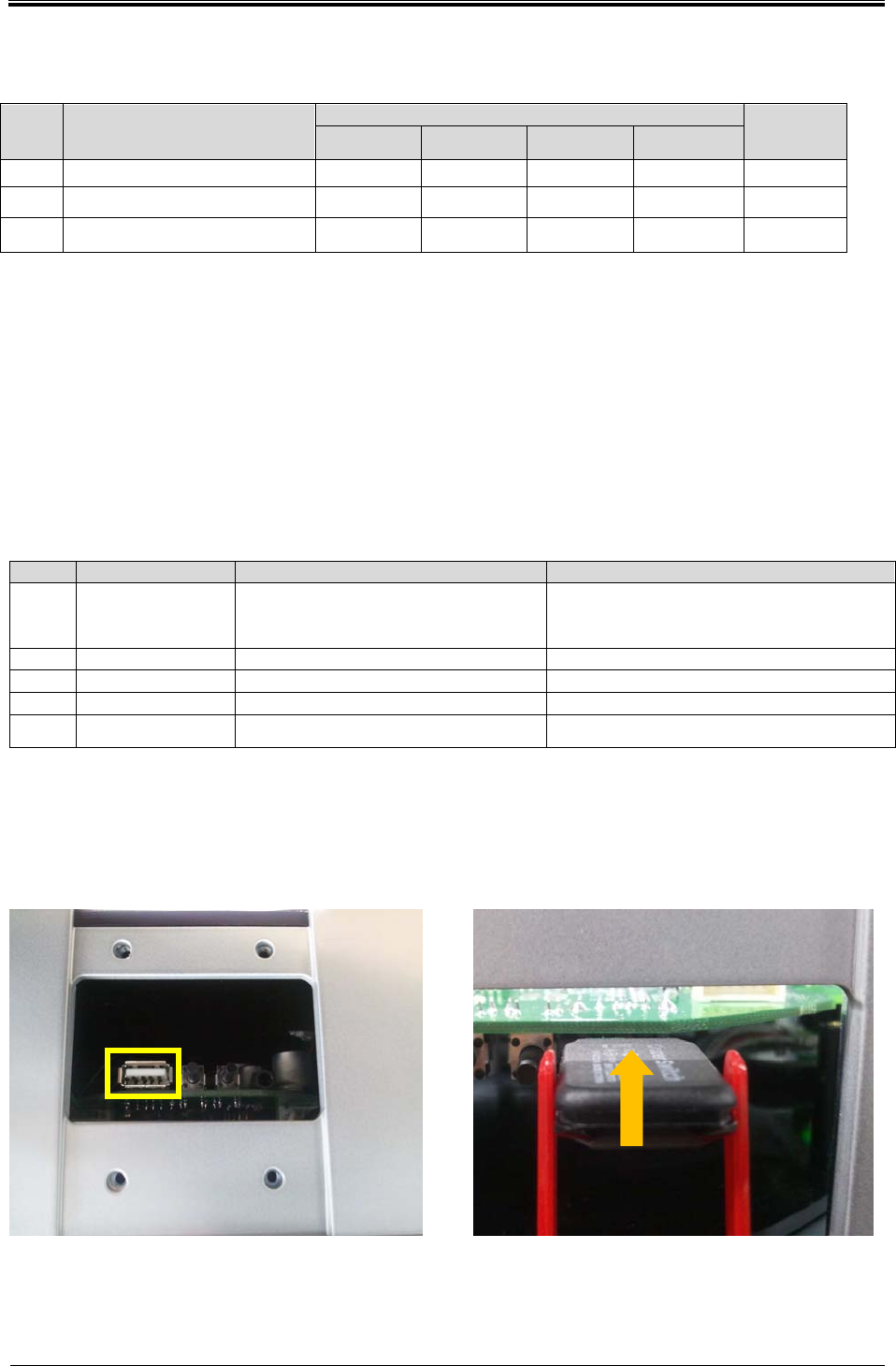
4.1.2 Device registration
4.1.2.1 USB mounting method
① Turn OFF terminal.
② Insert USB to at the bottom of the USB PORT and turn ON.
③ After update, disconnect USB from terminal and reboot.
Bogota SIRCI Project
User Requirement Definition
CB-EVA-HM-00-V1.0 Zonal Validator Page
19
1919
19
of All
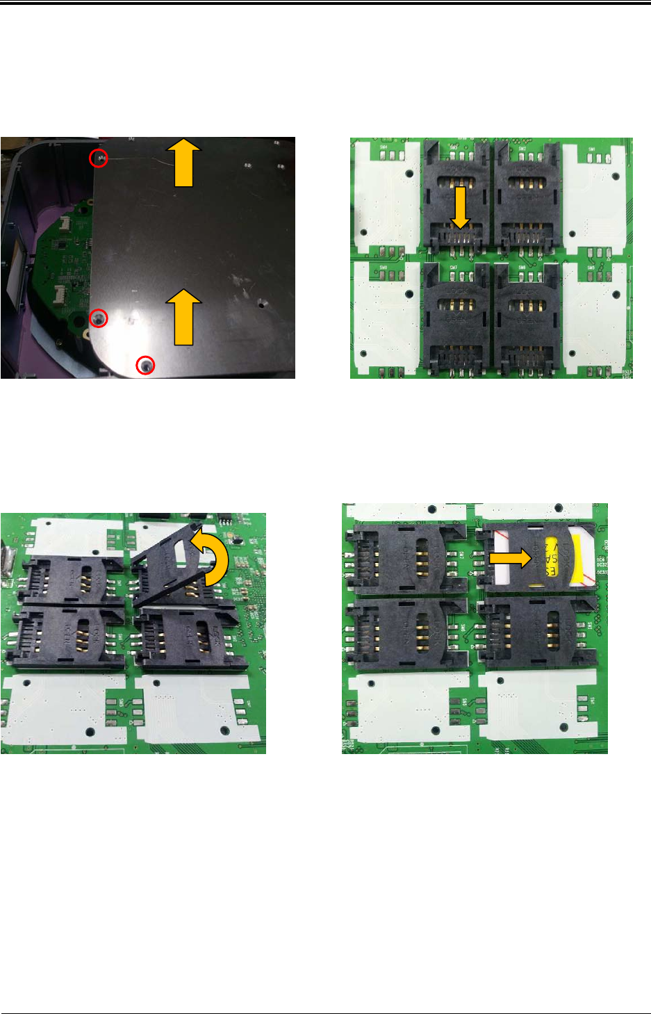
4.1.2.2 SAM mounting
<Picture 1> <Picture 2>
① Picture 1: Loosen fixed nut and separate back case.
② Push SAM socket in the direction of the arrow shown in picture 2, and lift like picture 3.
<Picture 3> <Picture 4>
③ After combined SAM, push and combine completely.
④ Combine all of SAM and assemble back case.
4.1.2.3 Power ON
① Connect adopter to outlet.
② When hear BUZZER, normal booting complete
< SIM CARD >

Bogota SIRCI Project
User Requirement Definition
CB-EVA-HM-00-V1.0 Zonal Validator Page
20
2020
20
of All
FCC Statement
This device complies with Part 15 of the FCC Rules. Operation is subject to the following two conditions:
(1) This device may not cause harmful interference. and
(2) This device must accept any interference received, including interference that may cause undesired
operation.
Any changes or modifications to the equipment not expressly approved by the party responsible for
compliance could void the user's authority to operate the equipment.
UNINTENTIONAL RADIATORS (Part15, Subpart B, 15.105)
Note: This equipment has been tested and found to comply with the limits for a Class B digital device,
pursuant to part 15 of the FCC Rules. These limits are designed to provide reasonable protection against
harmful interference in a residential installation.
This equipment generates, uses and can radiate radio frequency energy and, if not installed and used in
accordance with the instructions, may cause harmful interference to radio communications. However,
there is no guarantee that interference will not occur in a particular installation. If this equipment does
cause harmful interference to radio or television reception, which can be determined by turning the
equipment off and on, the user is encouraged to try to correct the interference by one or more of the
following measures:
- Reorient or relocate the receiving antenna.
- Increase the separation between the equipment and receiver.
- Connect the equipment into an outlet on a circuit different from that to which the receiver is connected.
- Consult the dealer or an experienced radio/TV technician for help.