LG CNS KSCCCBR310 ATTENDED RECHARGER User Manual WIDTHBMYMPHY
LG CNS CO., LTD. ATTENDED RECHARGER WIDTHBMYMPHY
UserManual.wiki
>
LG CNS
>
KSCCCBR310 User Manual
Users Manual
Navigation menu
Upload a User Manual
Namespaces
Wiki Guide
HTML
PDF
Info
Views
User Manual
Discussion / Help
Navigation
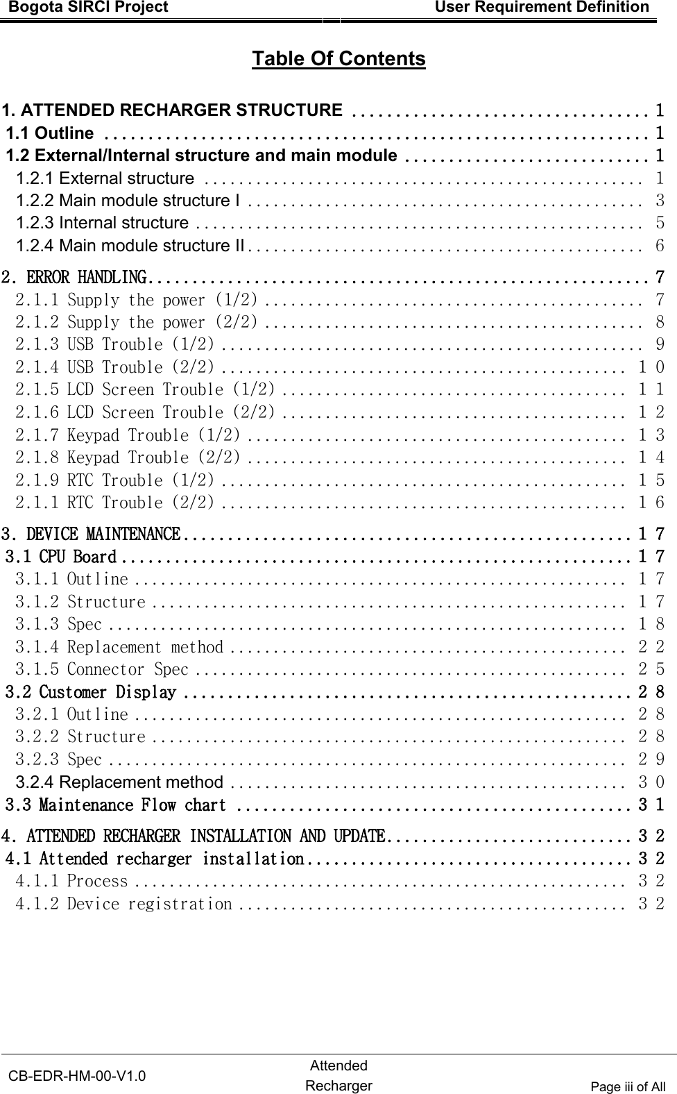
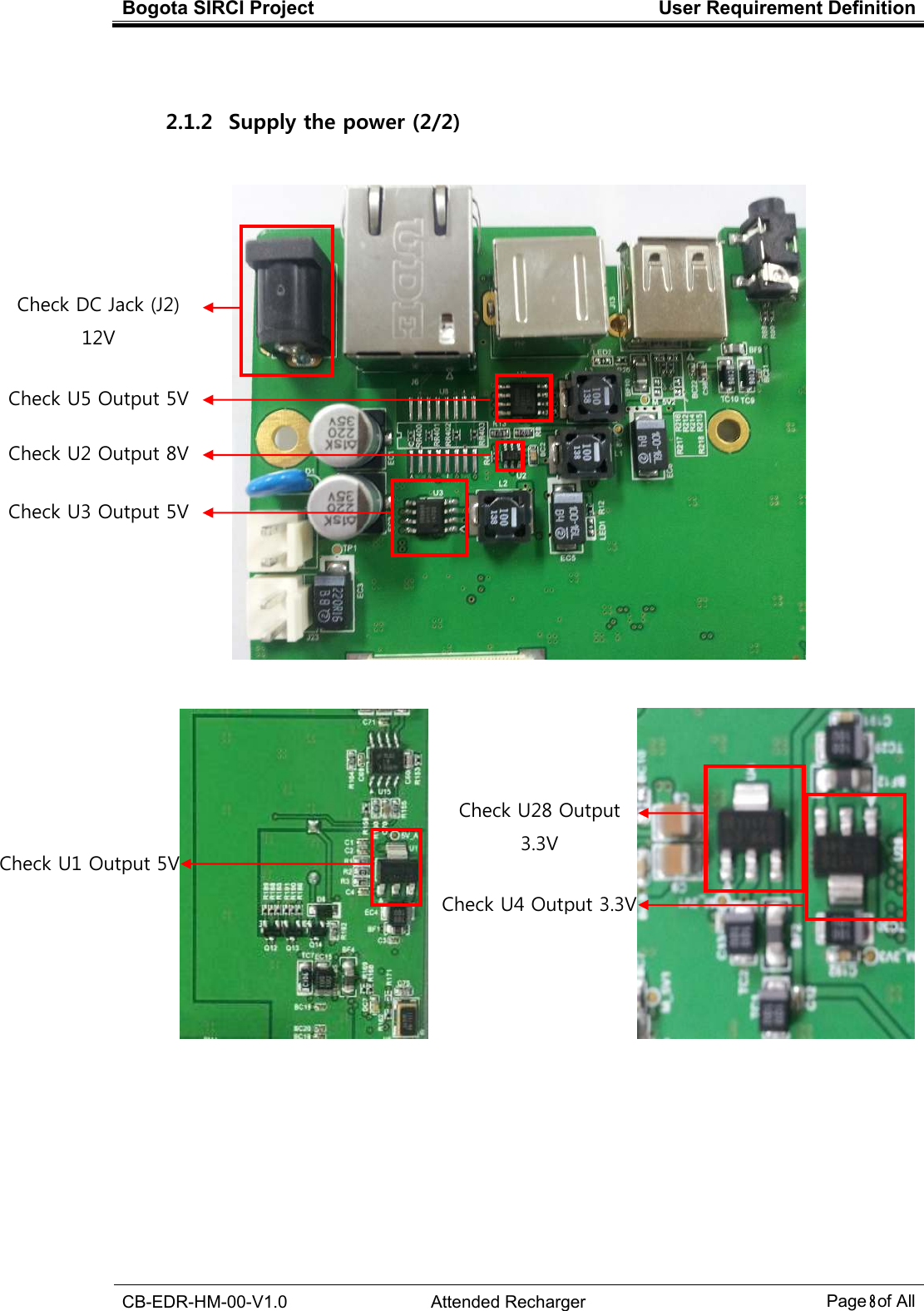
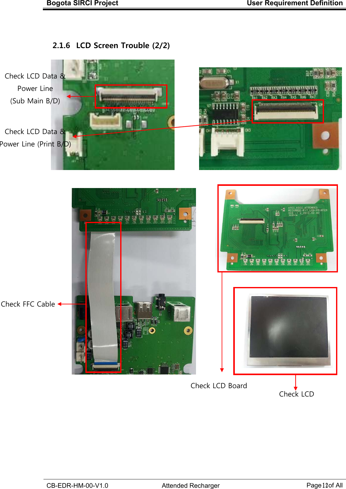
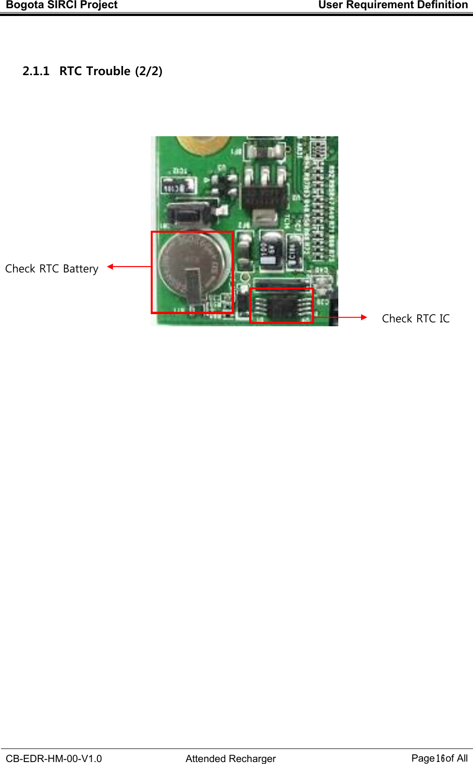
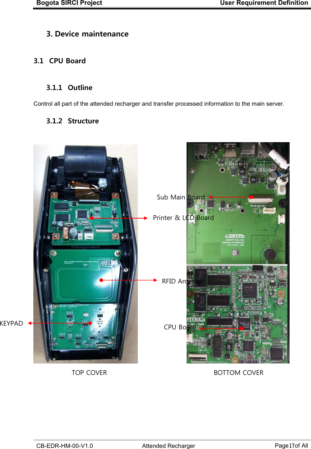
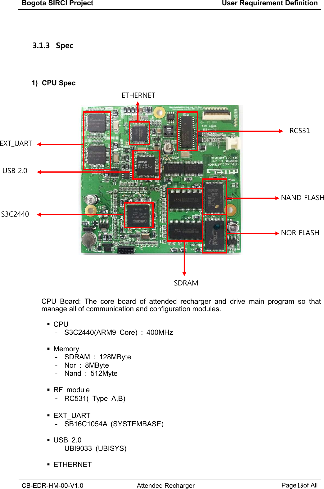
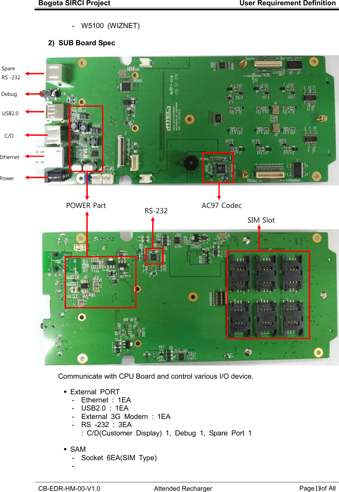
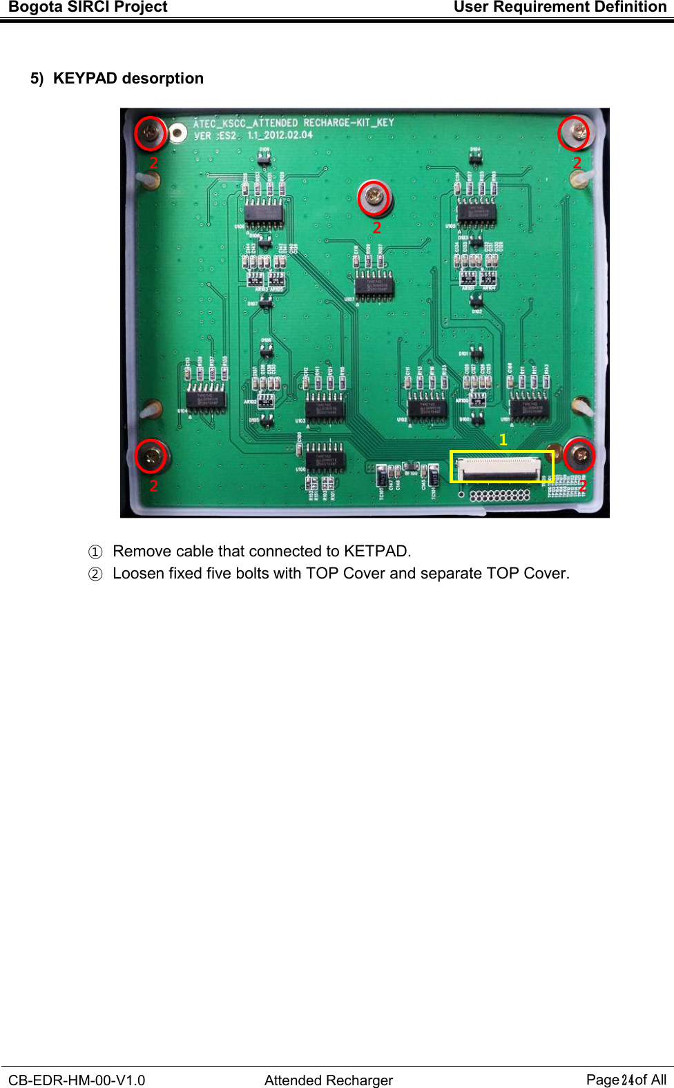
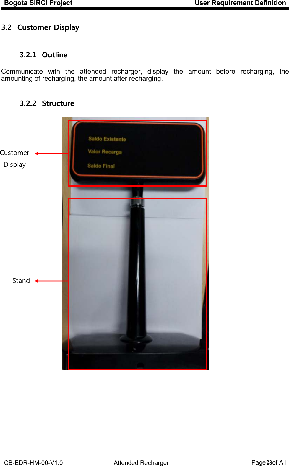
![Bogota SIRCI Project User Requirement Definition CB-EDR-HM-00-V1.0 Attended Recharger Page1 of All 1. Attended recharger structure 1.1 Outline Attended recharger is the device that recharges passenger’s card and managed by the crews. 1.2 External/Internal structure and main module 1.2.1 External structure [Attended Recharger] 132mm (W) 320mm (D) 185mm (H)](https://usermanual.wiki/LG-CNS/KSCCCBR310/User-Guide-1668227-Page-5.png)
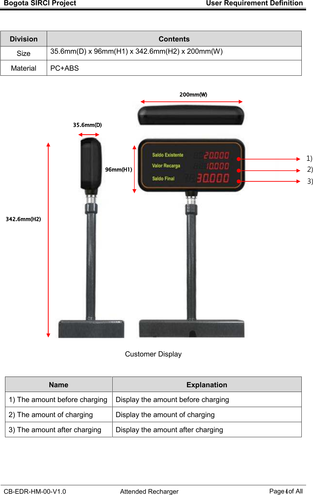
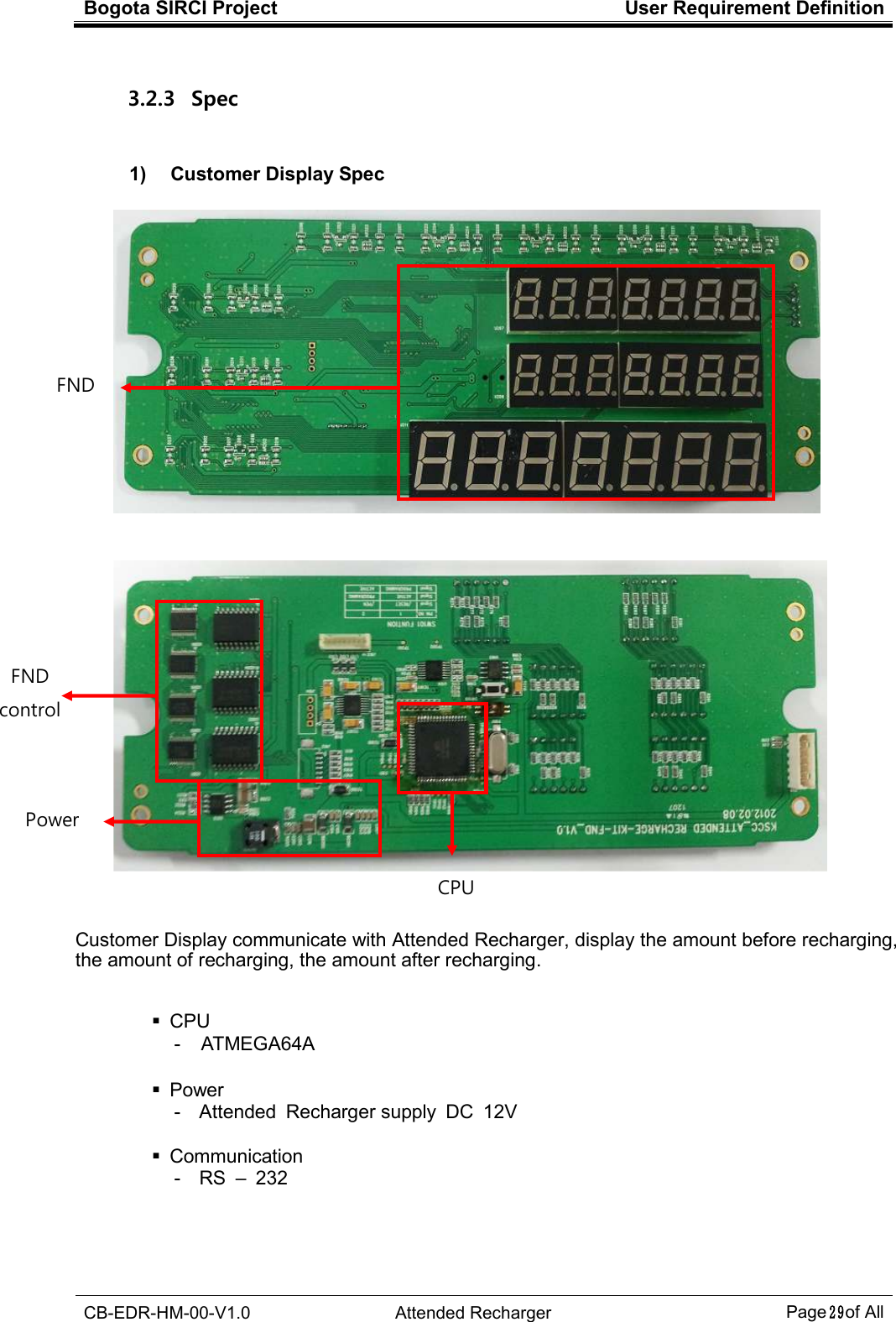
![Bogota SIRCI Project User Requirement Definition CB-EDR-HM-00-V1.0 Attended Recharger Page2 of All [Customer Display] 200mm (W) 35.6mm (D) 96mm (H) 342.6mm (H)](https://usermanual.wiki/LG-CNS/KSCCCBR310/User-Guide-1668227-Page-6.png)
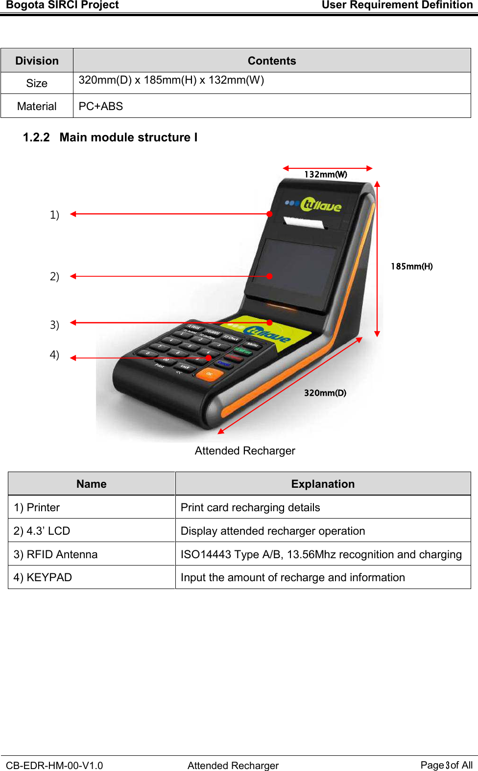
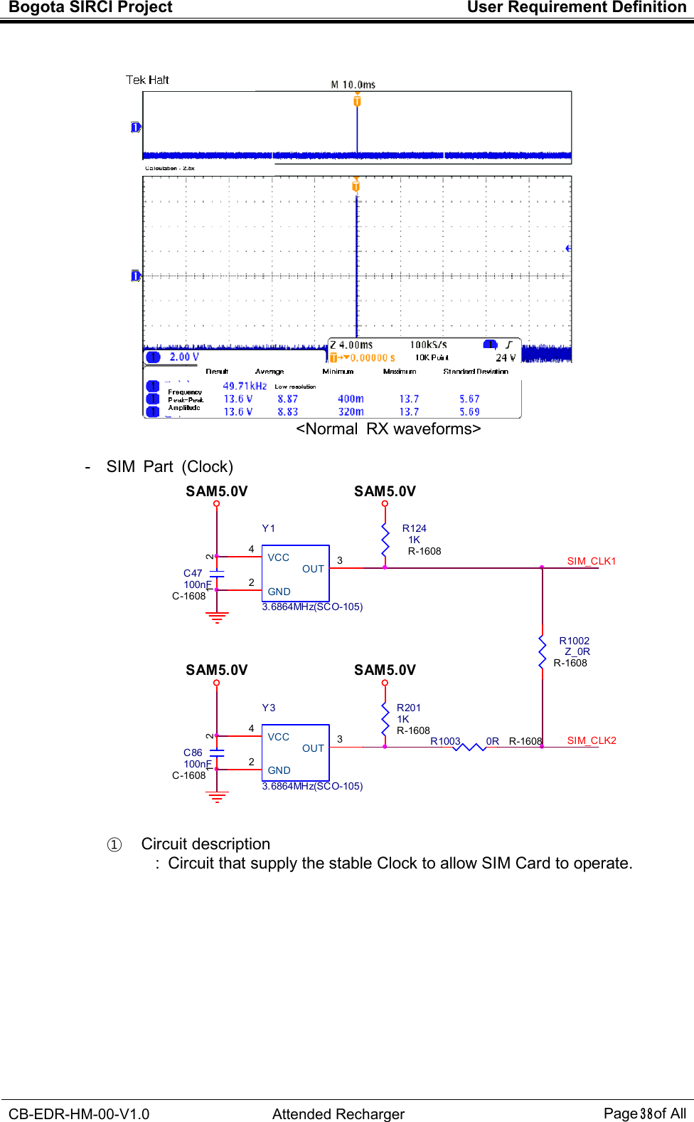
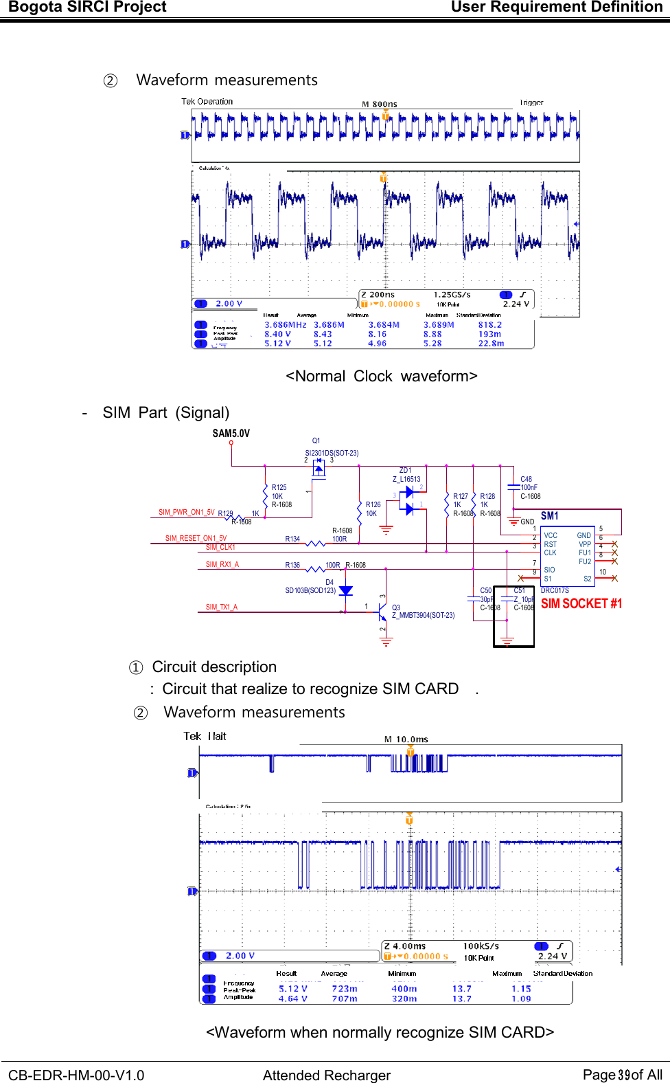
![Bogota SIRCI Project User Requirement Definition CB-EDR-HM-00-V1.0 Attended Recharger Page37 of All 4.1.3.3 Sub Main I/O - RS-232 PRIN T_DTR[3]123J145749181-1(DIN_CON)TX_DI SP1RX_DISP2GND3GND456<J8 Pin Assign>4<2011.12.9 >- NET (CUSTOM_232_TX/CUSTOM_232_RX)Spare RS-232C / PRINTER MODULE* SELECTION Of PRINT 232-LEVEL 213<J14 Pin Assign>4J85749267-1(DIN_CON)12V_DISP112V_DISP212V_DISP3TX_DI SP4RX_DISP5GND6GND7GND8CUSTOM_RX[3]VDD_3.3VTC310uF/16VTC-3216-A12CUSTOM_TX[3]VDD_3.3VR91 1K R -1005R88 100R R-1005R95 1K R-1005R90 100R R-1005C39 100nFC-1005CPU DEBUGERDBG_TX[3] DBG_TXDBG_RX[3] DBG_RXJ7TSH-3813STEREO-JACK-SH381D -PA9T-A231C37 100nFC-1005R316 100RC38 100nFC-1005R86 100R R-1005R92 100R R-1005R87 1K R -1005C36 100nFC-1005R93 1K R-1005U9SP3232EYTSSOP16C1+1C1-3C2+4C2-5T1IN11T2IN10R1OUT12R2OUT9GND15T1OUT 14T2OUT 7R1IN 13R2IN 8VCC 16V- 6V+ 2R89 100R R-1005R94 100R R-1005CUSTOM_232_RXC40 100nFC-1005CUSTOM_232_TXCustomer Display RS-232C12V_DISPJ9SMW200-5PSMW200-0512345RR500 100R R-1005C44 100nFC-1005R97 33R R -1005C42 100nFC-1005R98 100R R-1005PRIN T_232_RXR102 100R R-1005PRI NT_RXPRI NT_TXR96 100R R-1005U10SP3232EYTSSOP16C1+1C1-3C2+4C2-5T1IN11T2IN10R1OUT12R2OUT9GND15T1OUT 14T2OUT 7R1IN 13R2IN 8VCC 16V- 6V+ 2R103 33R R-1005R101 33R R-1005C45 100nFC-1005C43 100nFC-1005+EC710uF/16VTC-3216-AR100 100R R-1005R99 33R R -1005C41 100nFC-1005VDD_3.3VPRIN T_232_TXVDD_3.3VPRI NT_TX[3]EXT-UAR T_TXEXT-UAR T_RXPRI NT_RX[3]R106 Z_100RR107 Z_100RPRIN T_TXDECO_LED #1[3]PRIN T_RXPRI NT_232_TX R104 100RPRI NT_232_RX R105 100R<2011.12.9 >- J9 (3P->5P)- RR500(1005) , NET 78<2011.12.10 >Spare RS-232C ① Circuit desctiprion : Circuis that change UART signal into RS -232 signal ② Waveform measurements <Normal TX waveforms>](https://usermanual.wiki/LG-CNS/KSCCCBR310/User-Guide-1668227-Page-41.png)