LG CNS KSCCCBR310 ATTENDED RECHARGER User Manual WIDTHBMYMPHY
LG CNS CO., LTD. ATTENDED RECHARGER WIDTHBMYMPHY
LG CNS >
Users Manual
Sistema de Recaudo Control e Información y
Servicio al Usuario Proyect
Maintenance and Repair Manual
(Heavy)
Equipment Name
CB-EDR-HM-00-V1.0
Copyright LG CNSⓒ
It is forbidden to copy and distribute on certain or whole part of this content without precedent approval of LG CNS
Bogota SIRCI Project
User Requirement Definition
CB-EDR-HM-00-V1.0 Attended
Recharger Page i of All
Document Prepared by: Reviewed by: Approved by:
Maintenance and
Repair Manual (Heavy)
Bogota SIRCI Project
User Requirement Definition
CB-EDR-HM-00-V1.0 Attended
Recharger Page ii of All
Document History
Previous
Version
Present
Document
Date Numeral Changes Type

Bogota SIRCI Project
User Requirement Definition
CB-EDR-HM-00-V1.0 Attended
Recharger Page iii of All
Table Of Contents
1. ATTENDED RECHARGER STRUCTURE .................................. 1
1.1 Outline .............................................................. 1
1.2 External/Internal structure and main module ............................ 1
1.2.1 External structure ................................................... 1
1.2.2 Main module structure I .............................................. 3
1.2.3 Internal structure .................................................... 5
1.2.4 Main module structure II .............................................. 6
2. ERROR HANDLING ......................................................... 7
2.1.1 Supply the power (1/2) ............................................ 7
2.1.2 Supply the power (2/2) ............................................ 8
2.1.3 USB Trouble (1/2) ................................................. 9
2.1.4 USB Trouble (2/2) ............................................... 10
2.1.5 LCD Screen Trouble (1/2) ........................................ 11
2.1.6 LCD Screen Trouble (2/2) ........................................ 12
2.1.7 Keypad Trouble (1/2) ............................................ 13
2.1.8 Keypad Trouble (2/2) ............................................ 14
2.1.9 RTC Trouble (1/2) ............................................... 15
2.1.1 RTC Trouble (2/2) ............................................... 16
3. DEVICE MAINTENANCE ................................................... 17
3.1 CPU Board .......................................................... 17
3.1.1 Outline ......................................................... 17
3.1.2 Structure ....................................................... 17
3.1.3 Spec ............................................................ 18
3.1.4 Replacement method .............................................. 22
3.1.5 Connector Spec .................................................. 25
3.2 Customer Display ................................................... 28
3.2.1 Outline ......................................................... 28
3.2.2 Structure ....................................................... 28
3.2.3 Spec ............................................................ 29
3.2.4 Replacement method .............................................. 30
3.3 Maintenance Flow chart ............................................. 31
4. ATTENDED RECHARGER INSTALLATION AND UPDATE............................ 32
4.1 Attended recharger installation ..................................... 32
4.1.1 Process ......................................................... 32
4.1.2 Device registration ............................................. 32
Bogota SIRCI Project
User Requirement Definition
CB-EDR-HM-00-V1.0 Attended Recharger Page
1
of All
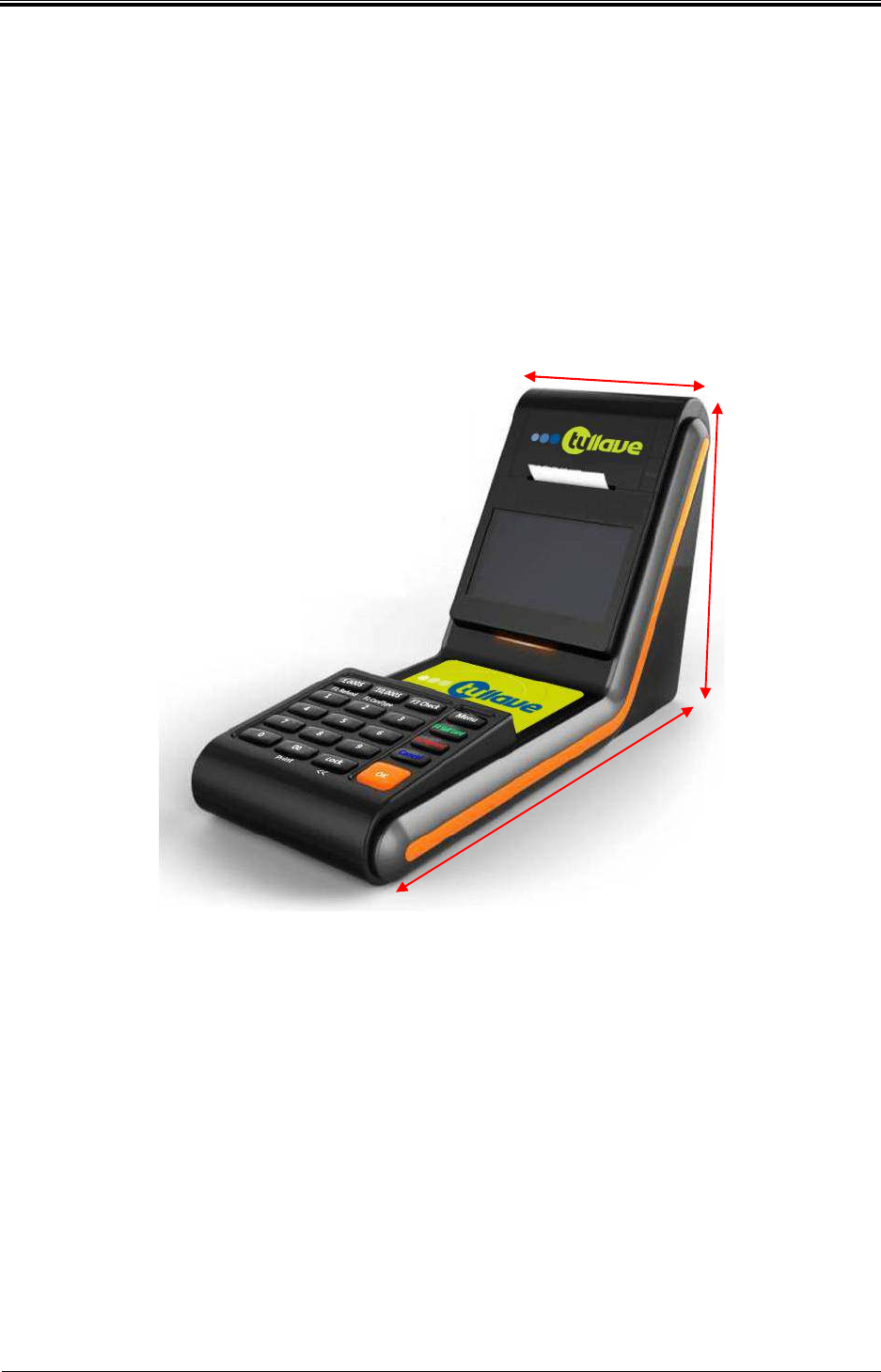
1. Attended recharger structure
1.1 Outline
Attended recharger is the device that recharges passenger’s card and managed by the crews.
1.2 External/Internal structure and main module
1.2.1 External structure
[Attended Recharger]
132mm (W)
320mm (D)
185mm (H)
Bogota SIRCI Project
User Requirement Definition
CB-EDR-HM-00-V1.0 Attended Recharger Page
2
of All
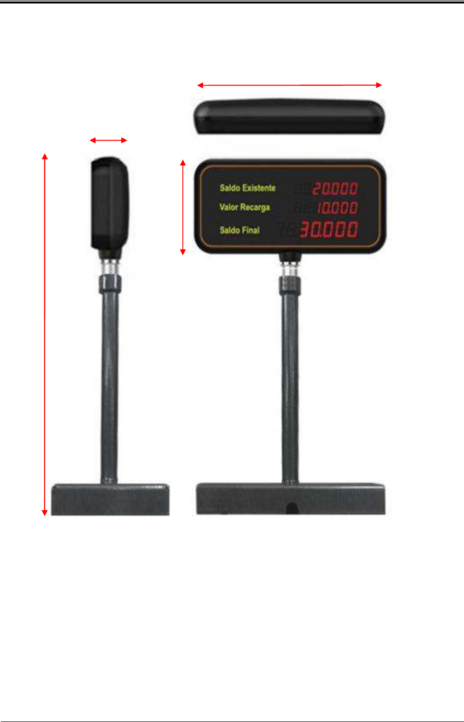
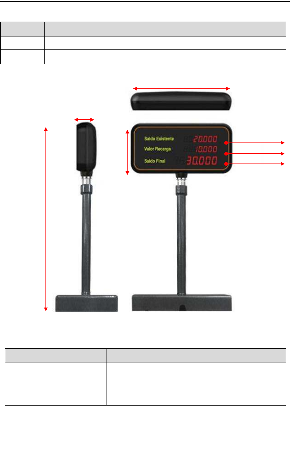
[Customer Display]
200mm (W)
35.6mm (D)
96mm (H)
342.6mm (H)
Bogota SIRCI Project
User Requirement Definition
CB-EDR-HM-00-V1.0 Attended Recharger Page
3
of All
Division Contents
Size 320mm(D) x 185mm(H) x 132mm(W)
Material PC+ABS
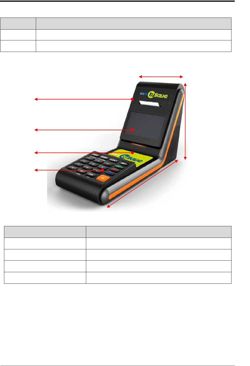
1.2.2 Main module structure I
Attended Recharger
Name Explanation
1) Printer Print card recharging details
2) 4.3’ LCD Display attended recharger operation
3) RFID Antenna ISO14443 Type A/B, 13.56Mhz recognition and charging
4) KEYPAD Input the amount of recharge and information
132mm(W)
1)
320mm(D)
2)
3)
4)
185mm(H)
Bogota SIRCI Project
User Requirement Definition
CB-EDR-HM-00-V1.0 Attended Recharger Page
4
of All
Division Contents
Size 35.6mm(D) x 96mm(H1) x 342.6mm(H2) x 200mm(W)
Material PC+ABS
Customer Display
Name Explanation
1) The amount before charging
Display the amount before charging
2) The amount of charging Display the amount of charging
3) The amount after charging Display the amount after charging
200mm(W)
35.6mm(D)
96mm(H1)
342.6mm(H2)
1)
2
)
3
)
Bogota SIRCI Project
User Requirement Definition
CB-EDR-HM-00-V1.0 Attended Recharger Page
5
of All
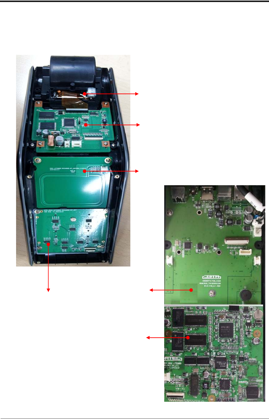
1.2.3 Internal structure
Printer Module
Printer & L
CD Board
RFID Antenna
KEYPAD Board
Sub Main Board
CPU Board

Bogota SIRCI Project
User Requirement Definition
CB-EDR-HM-00-V1.0 Attended Recharger Page
6
of All
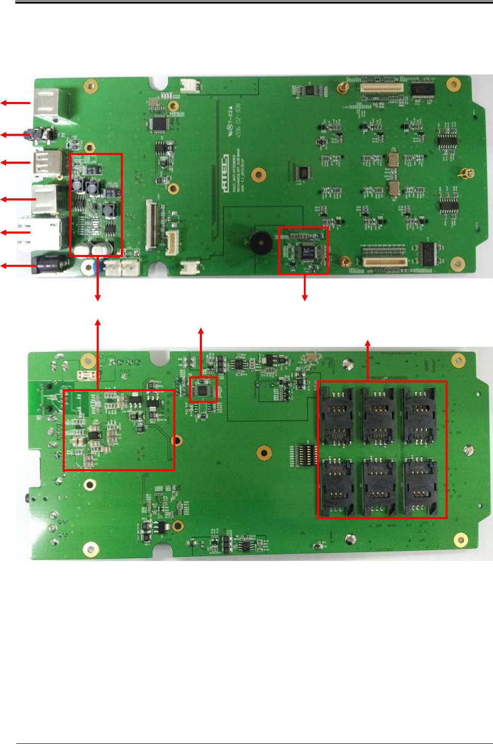
1.2.4 Main module structure II
1) 4.3’ LCD
Display attended recharger operation
2) Printer
Print various finishes, accounting journals and data etc.
3) RFID Antenna
RF interface that be able to read 13.56MHz RF Card
Available card : ISO 14443 Type A, B
4) CPU Board
Control all part of the attended recharger and transfer processed information to the main server.
CPU
- S3C2440(ARM9 Core) : 400MHz
Memory
- SDRAM : 128MByte
- Nor : 8MByte
- Nand : 512Myte
RF module
- RC531( Type A,B)
5) Sub Board
Communicate with CPU Board and control I/O devices.
External PORT
- Ethernet : 1EA
- USB 2.0 : 1EA
- External 3G Modem : 1EA
- RS -232 : 3EA
SAM
- Socket 6EA(SIM Type)
Sound
- SW Codec control
- Speaker : 1W * 2 EA
Bogota SIRCI Project
User Requirement Definition
CB-EDR-HM-00-V1.0 Attended Recharger Page
7
of All
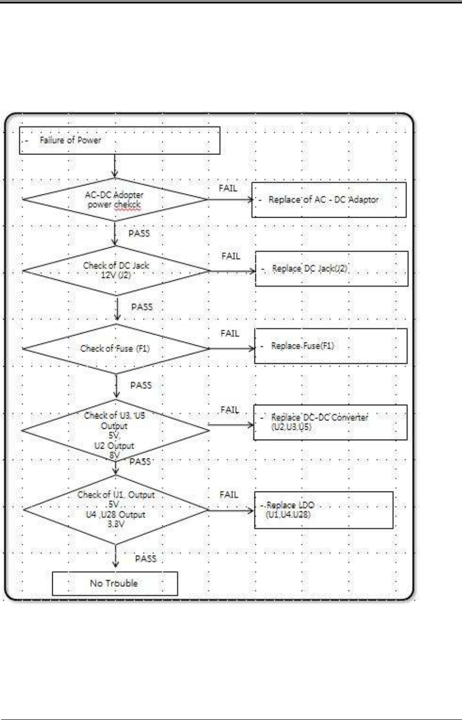
2. Error handling
2.1.1 Supply the power (1/2)
Bogota SIRCI Project
User Requirement Definition
CB-EDR-HM-00-V1.0 Attended Recharger Page
8
of All
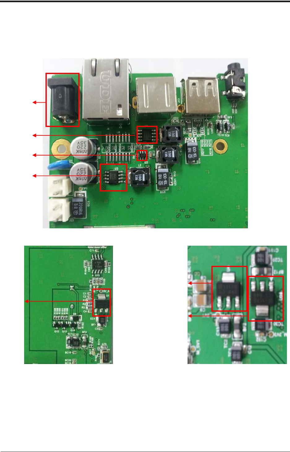
2.1.2 Supply the power (2/2)
Check U5 Output 5V
Check U2 Output 8V
Check U3 Output 5V
Check U28 Output
3.3V
Check
U
1 Output
5V
Check
U
4
Out
p
ut
3.3
V
Check DC Jack (J2)
12V
Bogota SIRCI Project
User Requirement Definition
CB-EDR-HM-00-V1.0 Attended Recharger Page
9
of All
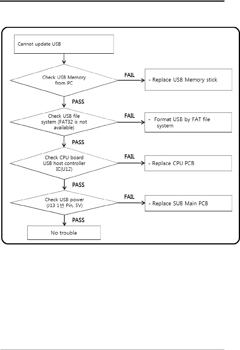
2.1.3 USB Trouble (1/2)
Bogota SIRCI Project
User Requirement Definition
CB-EDR-HM-00-V1.0 Attended Recharger Page
10
of All
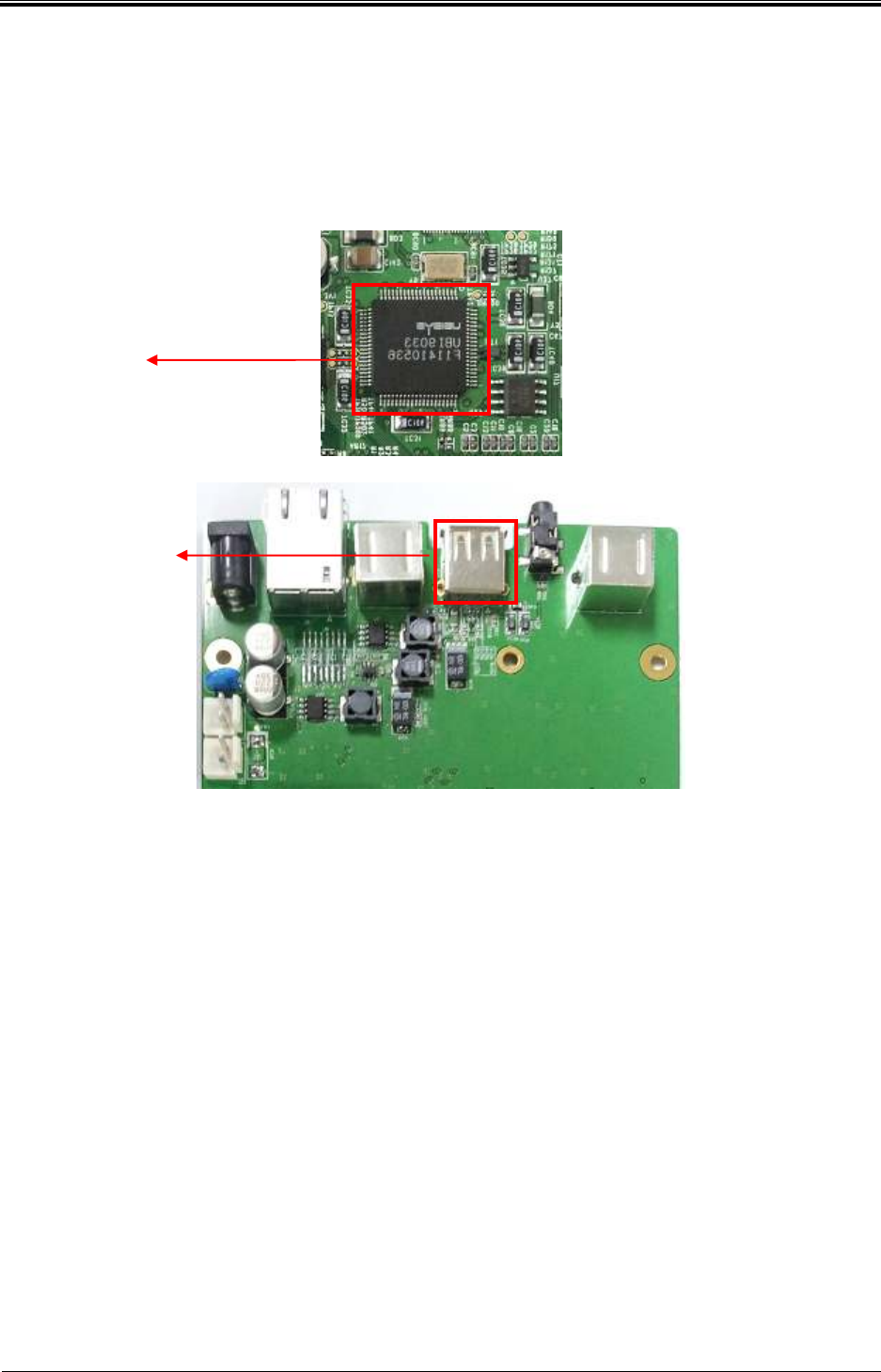
2.1.4 USB Trouble (2/2)
Check U21 USB HOST
Controller
Check USB Power
Pin No.1 and 5V
Bogota SIRCI Project
User Requirement Definition
CB-EDR-HM-00-V1.0 Attended Recharger Page
11
of All
2.1.5 LCD Screen Trouble (1/2)
Bogota SIRCI Project
User Requirement Definition
CB-EDR-HM-00-V1.0 Attended Recharger Page
12
of All
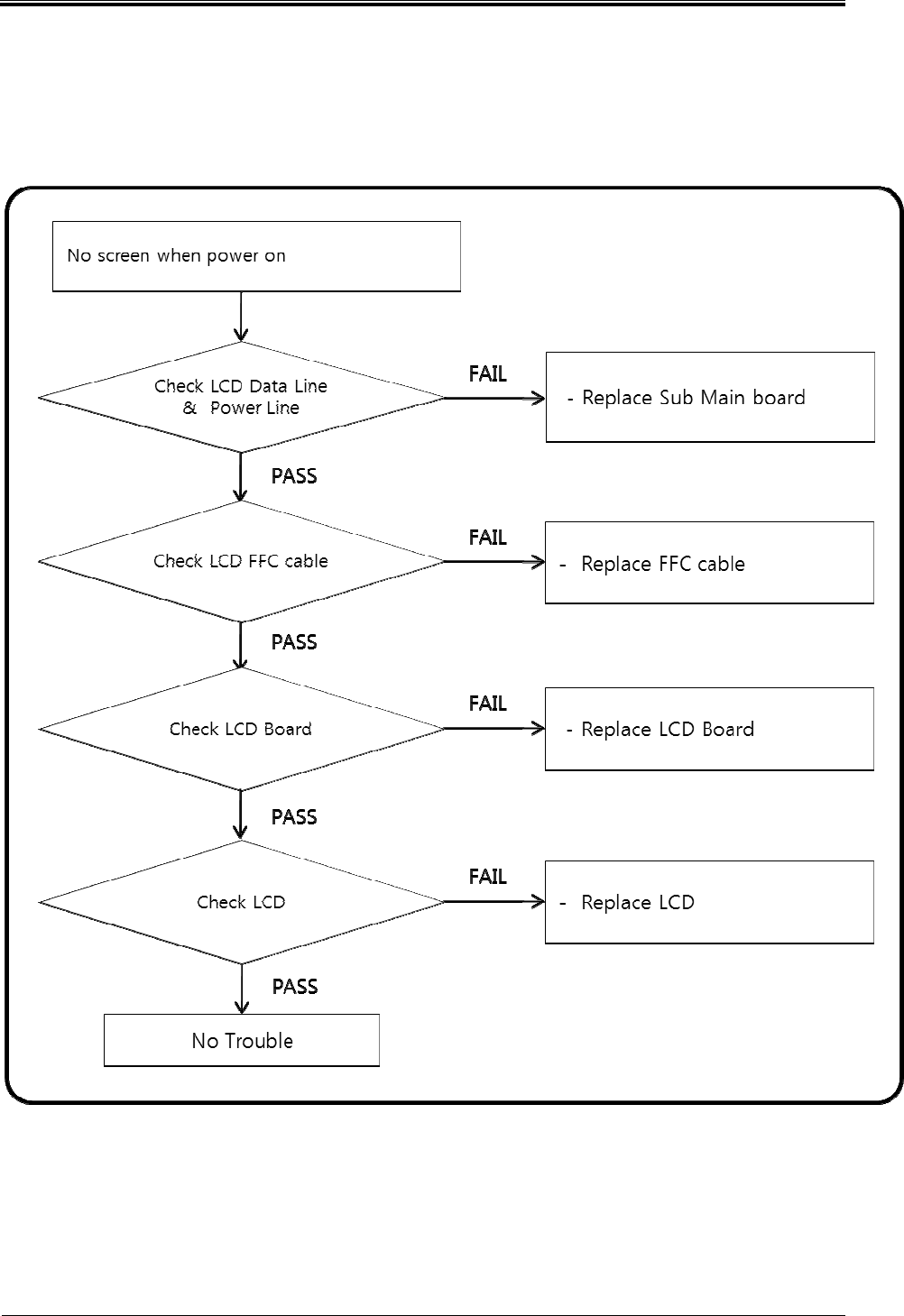
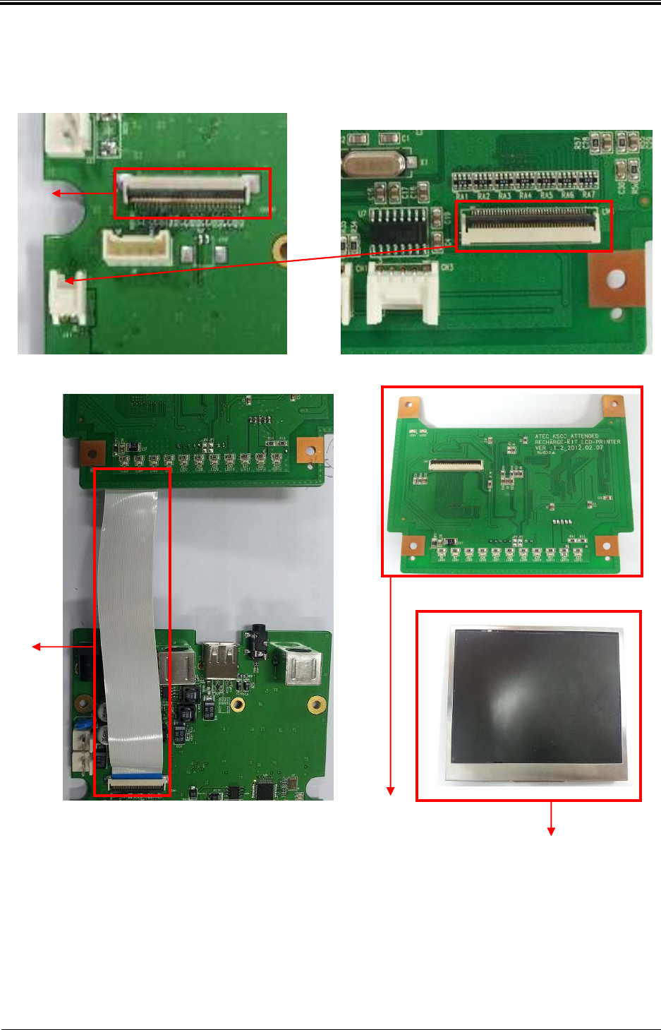
2.1.6 LCD Screen Trouble (2/2)
Check LCD Data &
Power Line
(Sub Main B/D)
Check LCD Data &
Power Line (Print B/D)
Check FFC Cable
Check LCD
Check LCD Board
Bogota SIRCI Project
User Requirement Definition
CB-EDR-HM-00-V1.0 Attended Recharger Page
13
of All
2.1.7 Keypad Trouble (1/2)
Bogota SIRCI Project
User Requirement Definition
CB-EDR-HM-00-V1.0 Attended Recharger Page
14
of All
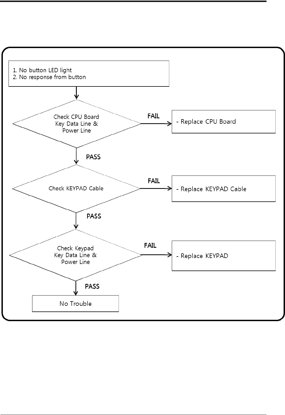
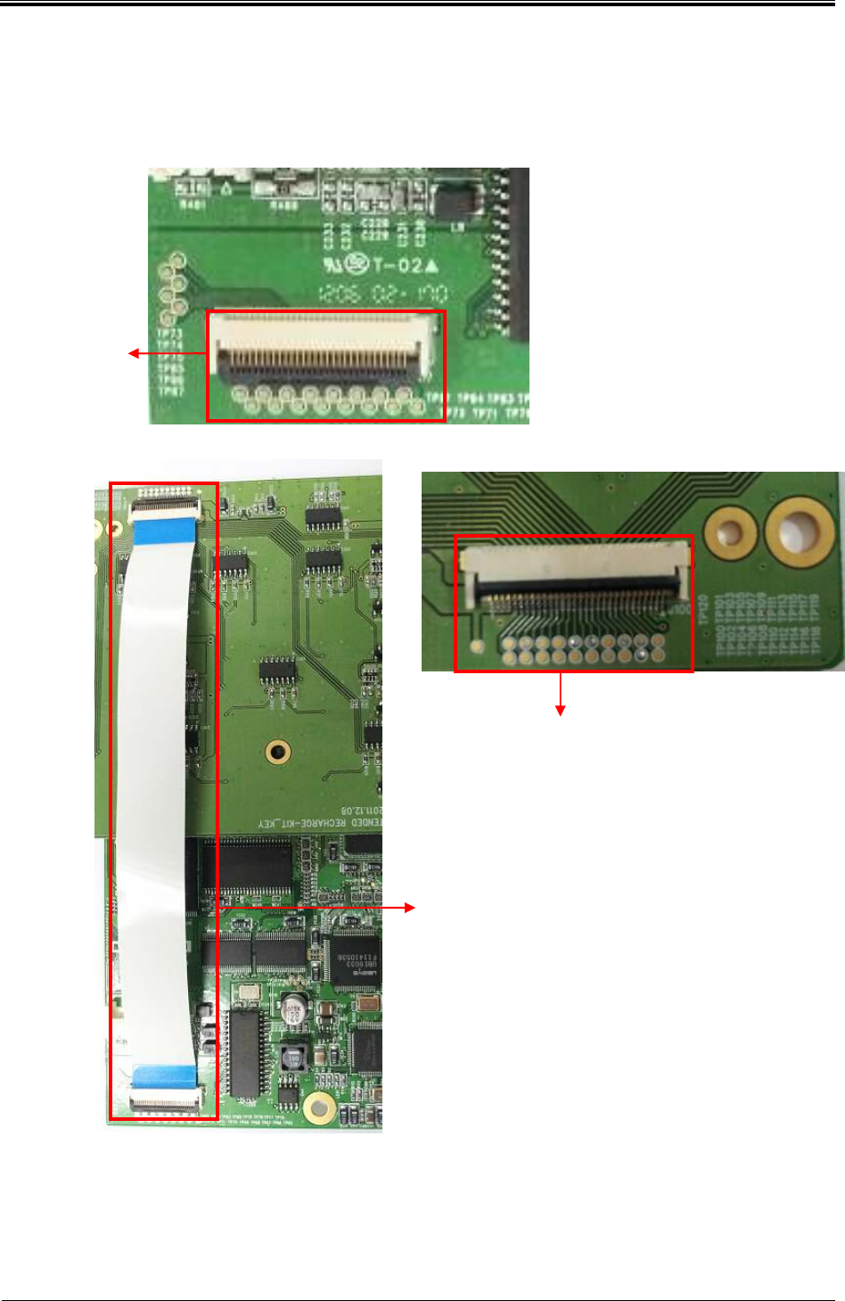
2.1.8 Keypad Trouble (2/2)
Check CPU Board
Key Data Line
& Power Line
Check KEYPAD
Cable
Check Key Board
Key Data Line
& Power Line
Bogota SIRCI Project
User Requirement Definition
CB-EDR-HM-00-V1.0 Attended Recharger Page
15
of All
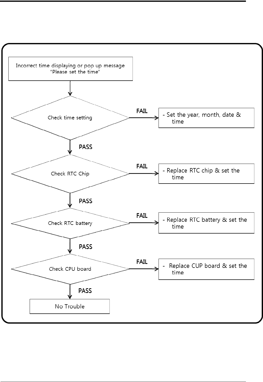
2.1.9 RTC Trouble (1/2)
Bogota SIRCI Project
User Requirement Definition
CB-EDR-HM-00-V1.0 Attended Recharger Page
16
of All
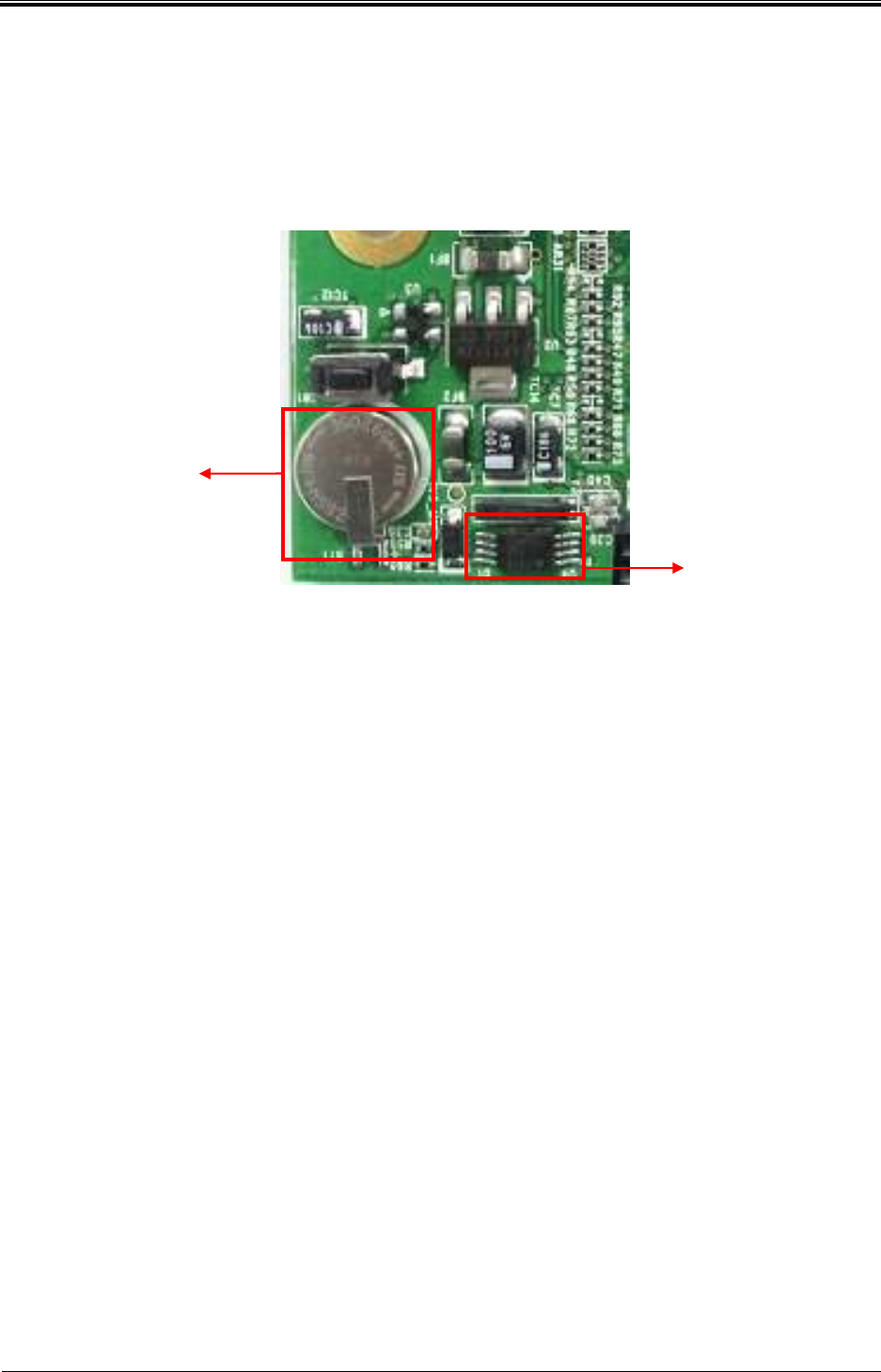
2.1.1 RTC Trouble (2/2)
Check RTC Battery
Check RTC IC
Bogota SIRCI Project
User Requirement Definition
CB-EDR-HM-00-V1.0 Attended Recharger Page
17
of All
3. Device maintenance
3.1 CPU Board
3.1.1 Outline
Control all part of the attended recharger and transfer processed information to the main server.
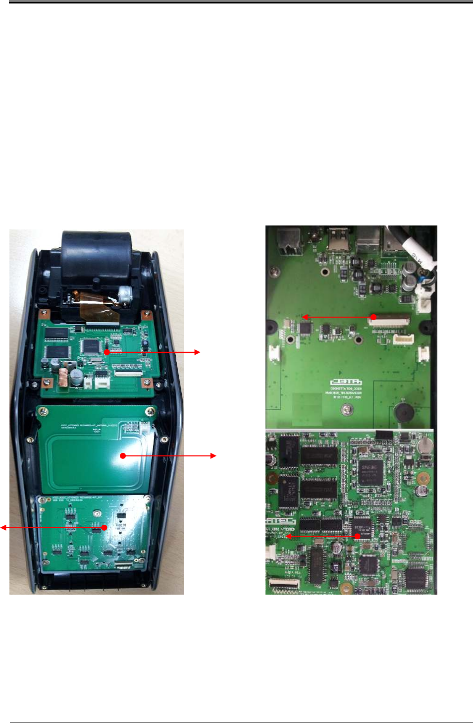
3.1.2 Structure
TOP COVER
BOTTOM COVER
Printer & LCD Board
RFID Antenna
KEYPAD
Sub Main Board
CPU Board
Bogota SIRCI Project
User Requirement Definition
CB-EDR-HM-00-V1.0 Attended Recharger Page
18
of All
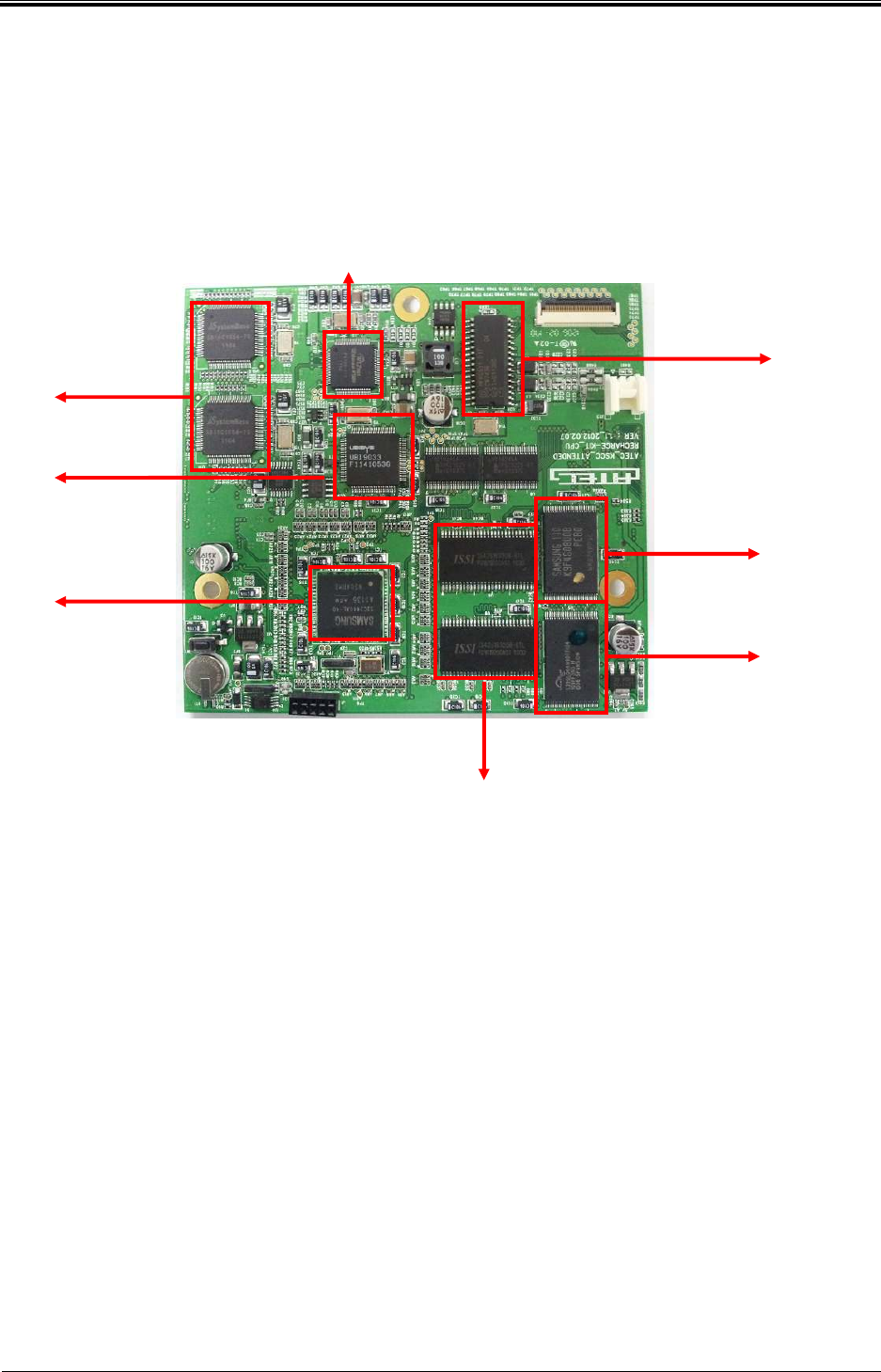
3.1.3 Spec
1) CPU Spec
CPU Board: The core board of attended recharger and drive main program so that
manage all of communication and configuration modules.
CPU
- S3C2440(ARM9 Core) : 400MHz
Memory
- SDRAM : 128MByte
- Nor : 8MByte
- Nand : 512Myte
RF module
- RC531( Type A,B)
EXT_UART
- SB16C1054A (SYSTEMBASE)
USB 2.0
- UBI9033 (UBISYS)
ETHERNET
EXT_UART
USB 2.0
S3C2440
RC531
ETHERNET
NAND FLASH
NOR FLASH
SDRAM
Bogota SIRCI Project
User Requirement Definition
CB-EDR-HM-00-V1.0 Attended Recharger Page
19
of All
- W5100 (WIZNET)
2) SUB Board Spec
Communicate with CPU Board and control various I/O device.
External PORT
- Ethernet : 1EA
- USB2.0 : 1EA
- External 3G Modem : 1EA
- RS -232 : 3EA
: C/D(Customer Display) 1, Debug 1, Spare Port 1
SAM
- Socket 6EA(SIM Type)
-
POW
ER Part
AC97 Codec
RS
-
232
SIM Slot
Spare
RS -232
Debug
USB2.0
C/D
Ethernet
Power
Bogota SIRCI Project
User Requirement Definition
CB-EDR-HM-00-V1.0 Attended Recharger Page
20
of All
Sound
- SW Codec control
- Speaker : 1W * 2ea
Input power
- DC 12V/5A, use adopter
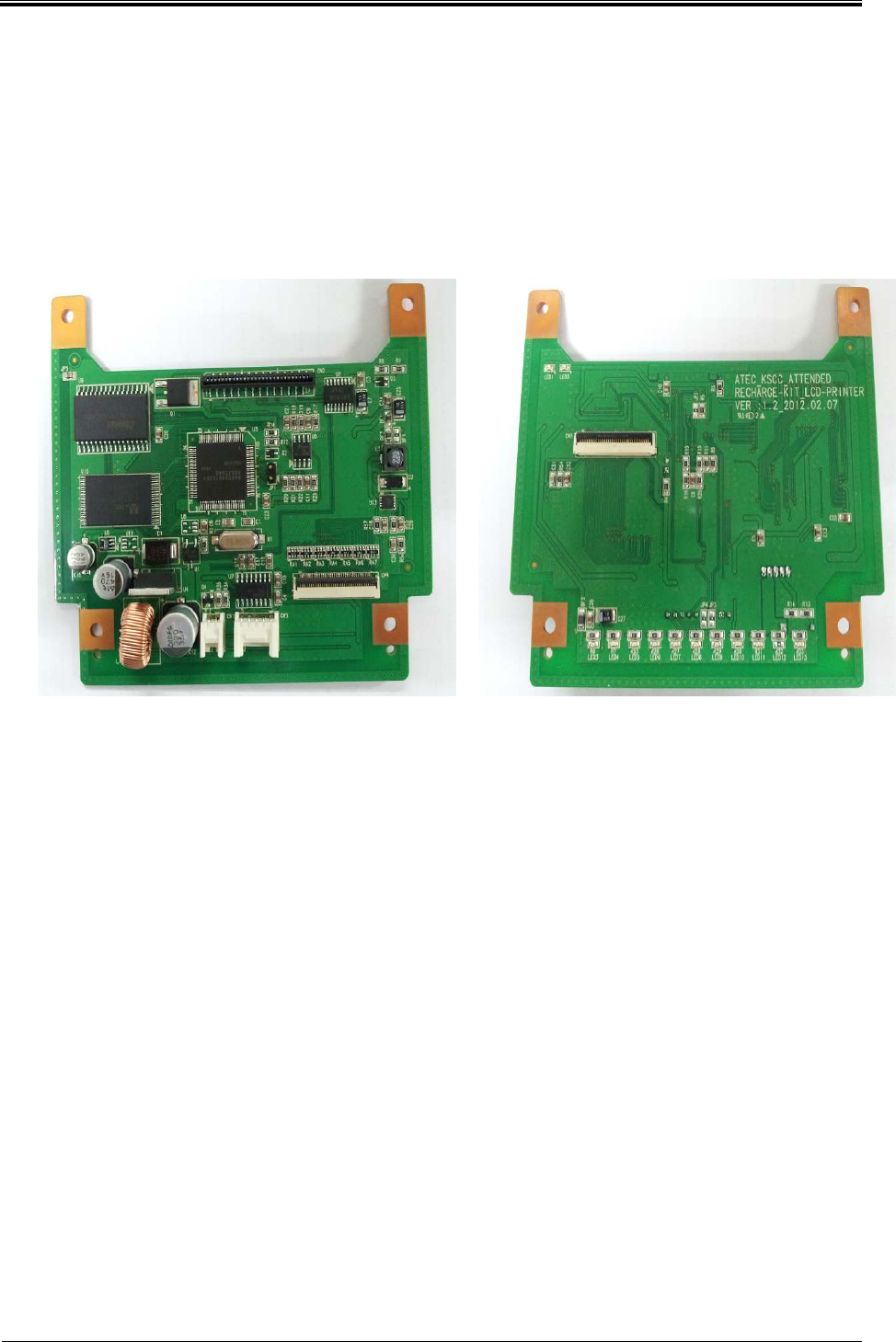
3) Printer & LCD Board Spec
Communicate with Sub Main Board and control Printer & LCD.
LCD
- DC 3.3V input, GPIO communication
Printer
- DC 12V input, RS-232 communication
Bogota SIRCI Project
User Requirement Definition
CB-EDR-HM-00-V1.0 Attended Recharger Page
21
of All
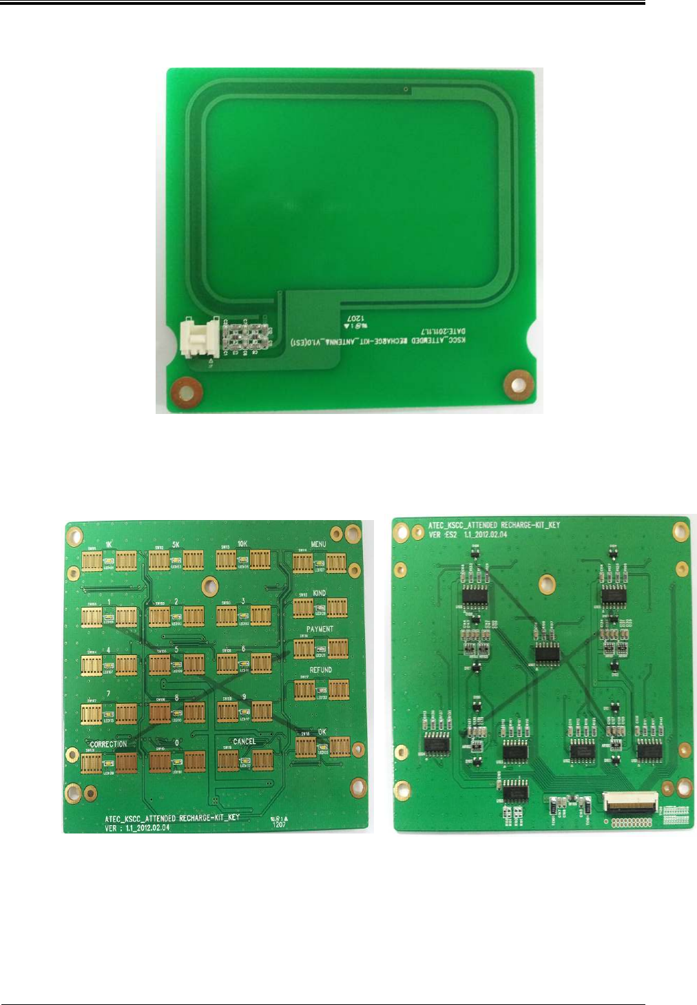
4) Antenna Board Spec
Connected at CPU Board RC531, recognize the card.
5) Keypad Spec
Transfer input key information to CPU Board.
Bogota SIRCI Project
User Requirement Definition
CB-EDR-HM-00-V1.0 Attended Recharger Page
22
of All
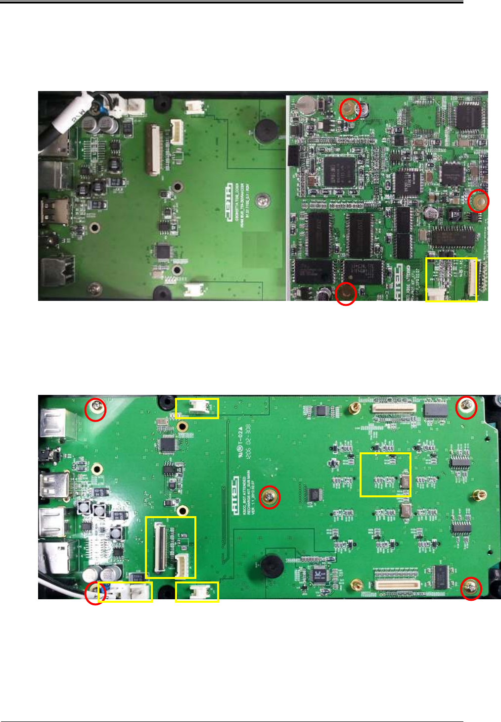
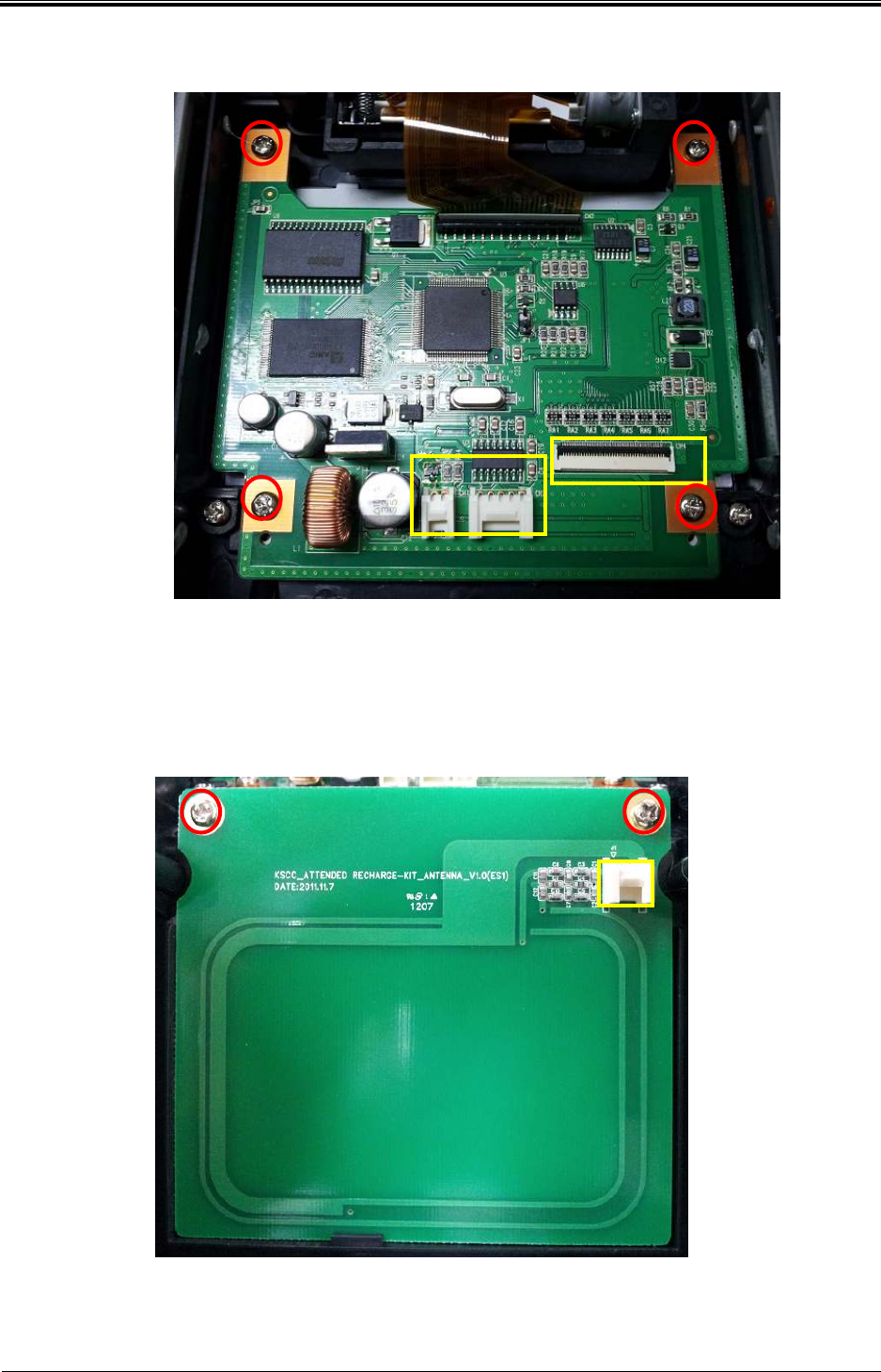
3.1.4 Replacement method
1) CPU board desorption
①Separate FFC Cable that associated with Keypad and 3Pin Connector the associated
with antenna board.
②Loosen the fixed bolts with Sub Board and separate Sub Board.
2) Sub Board desorption
①Remove the cable the connected to Sub Board.
②Loosen fixed five bolts with Bottom Cover and separate Bottom Cover.
1
2
2
2
2
2
1
1
1
1
1
2
2
2
Bogota SIRCI Project
User Requirement Definition
CB-EDR-HM-00-V1.0 Attended Recharger Page
23
of All
3) Printer & LCD Board desorption
① Remove cable that connected to Printer & LCD Board.
② Loosen fixed four bolts with TOP Cover and separate TOP Cover.
4) Antenna Board desorption
① Remove cable that connected to Antenna Board.
② Loosen fixed two bolts TOP Cover and separate TOP Cover.
2
1
1
2
2 2
1
2 2
Bogota SIRCI Project
User Requirement Definition
CB-EDR-HM-00-V1.0 Attended Recharger Page
24
of All
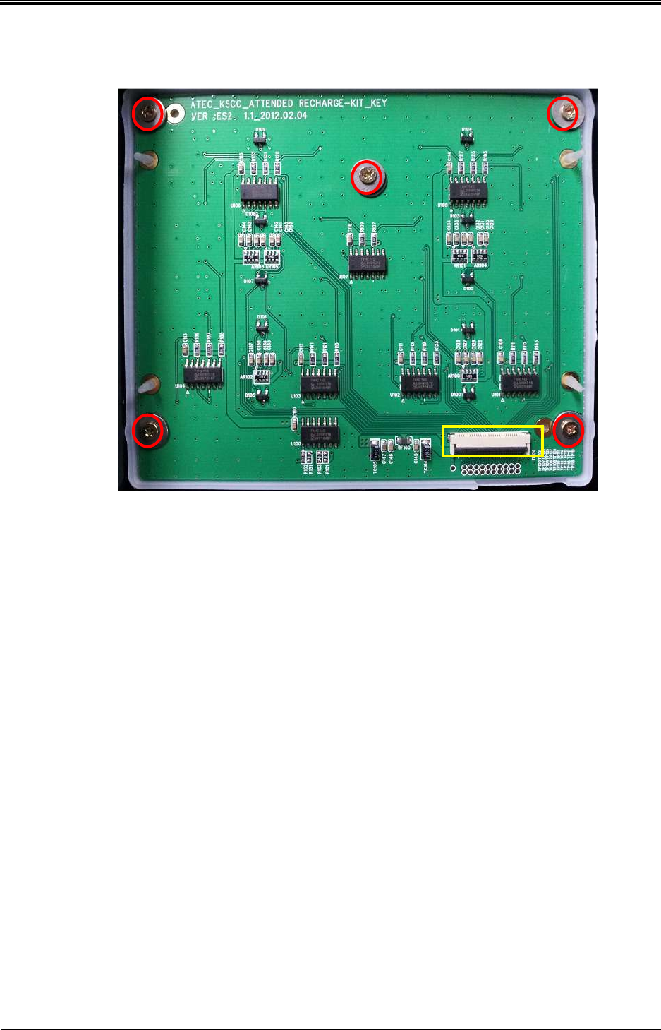
5) KEYPAD desorption
① Remove cable that connected to KETPAD.
② Loosen fixed five bolts with TOP Cover and separate TOP Cover.
1
2
2
2
2
2
Bogota SIRCI Project
User Requirement Definition
CB-EDR-HM-00-V1.0 Attended Recharger Page
25
of All
3.1.5 Connector Spec
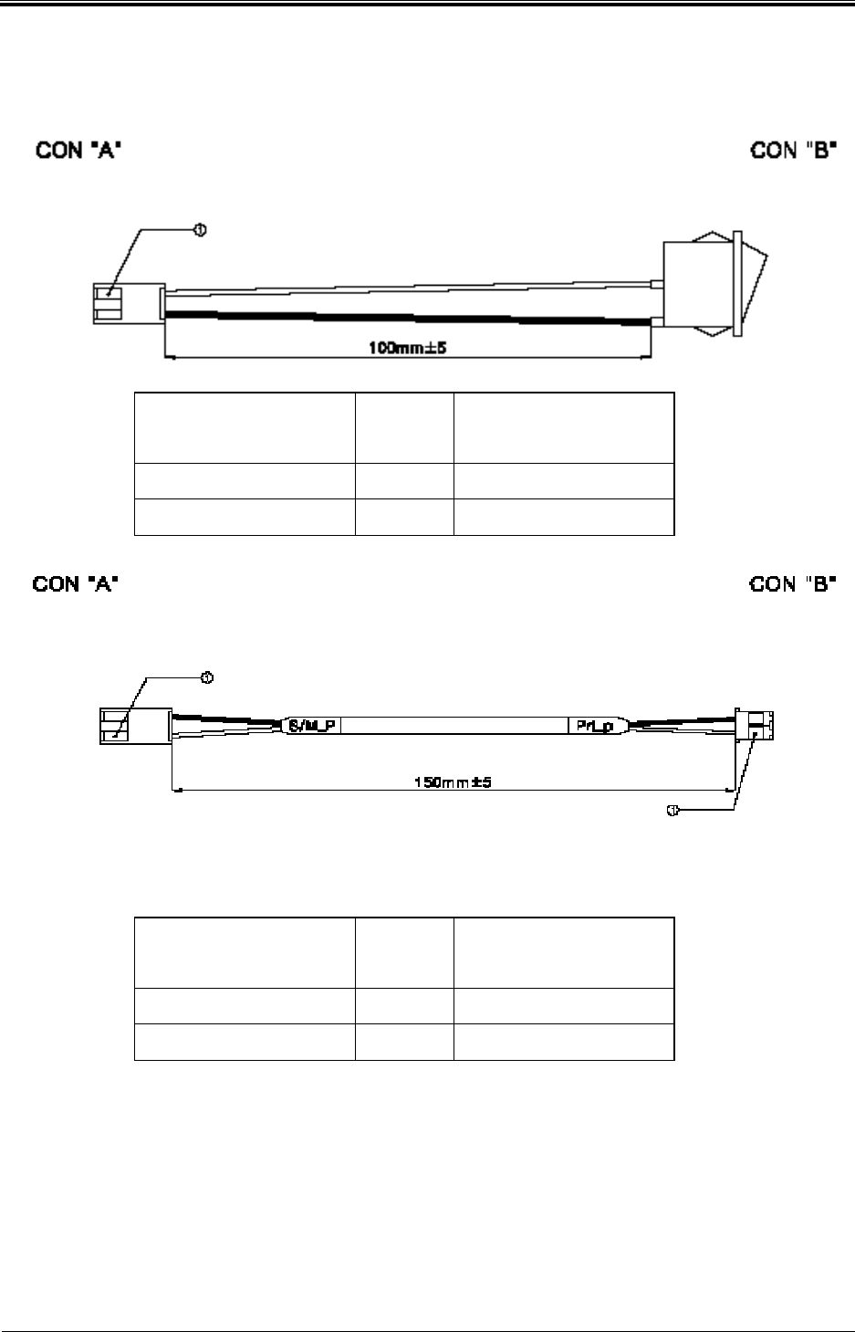
A. POWER Cable
CON 'A
'(SUB B/D J1)
CON 'B
'(SWITCH)
1 WHITE 1
1 BLACK 1A
B. PRINTER POWER Cable
CON 'A
'(SUB B/D J23)
CON 'B'
(PRINTER B/D CN1)
1 WHITE 1
2 BLACK 2
Bogota SIRCI Project
User Requirement Definition
CB-EDR-HM-00-V1.0 Attended Recharger Page
26
of All
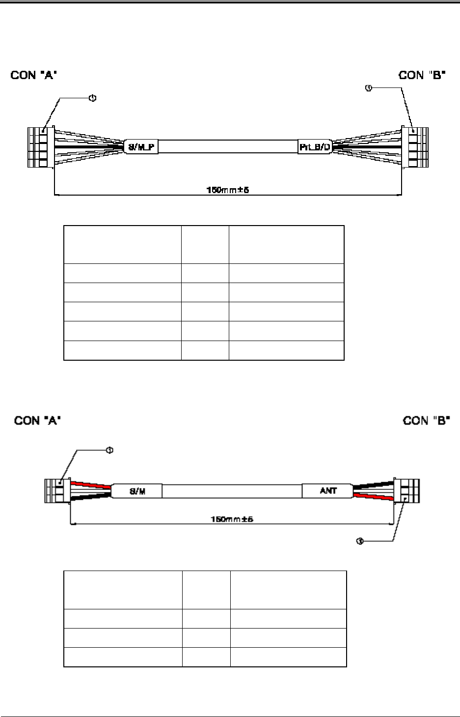
C. PRINTER DATA Cable
CON 'A'
(SUB B/D J9) CON 'B'
(PRINTER B/D CN3)
1 TX 2
2 RX 1
3 GND 3
4 DTR 4
5 DECO 5
D. Antenna Cable
CON 'A'
(CPU B/D J23) MATCH
CON 'B'
(ANTENNA B/D CN1)
1 RED 1
2 WHITE
2
3 GND 3
Bogota SIRCI Project
User Requirement Definition
CB-EDR-HM-00-V1.0 Attended Recharger Page
27
of All
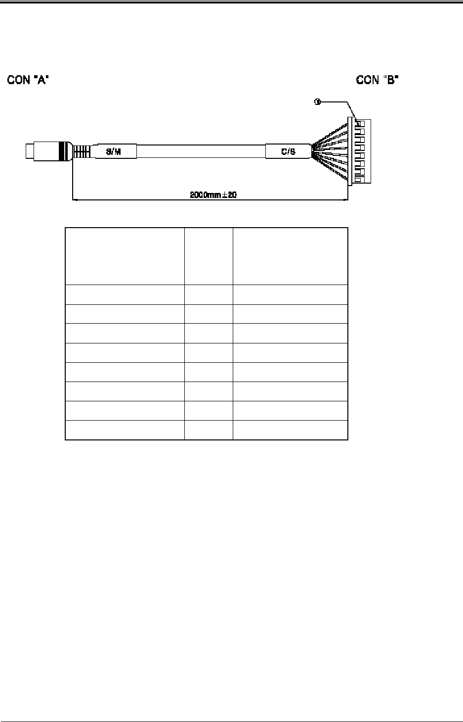
E. Customer Display
CON 'A'
(SUB B/D J8)
CON 'B'
(CUSTOM DISPALY
B/D J103)
1 VCC 1
2 VCC 2
3 TX 5
4 GND 6
5 VCC 3
6 GND 7
7 RX 4
8 GND 8
Bogota SIRCI Project
User Requirement Definition
CB-EDR-HM-00-V1.0 Attended Recharger Page
28
of All
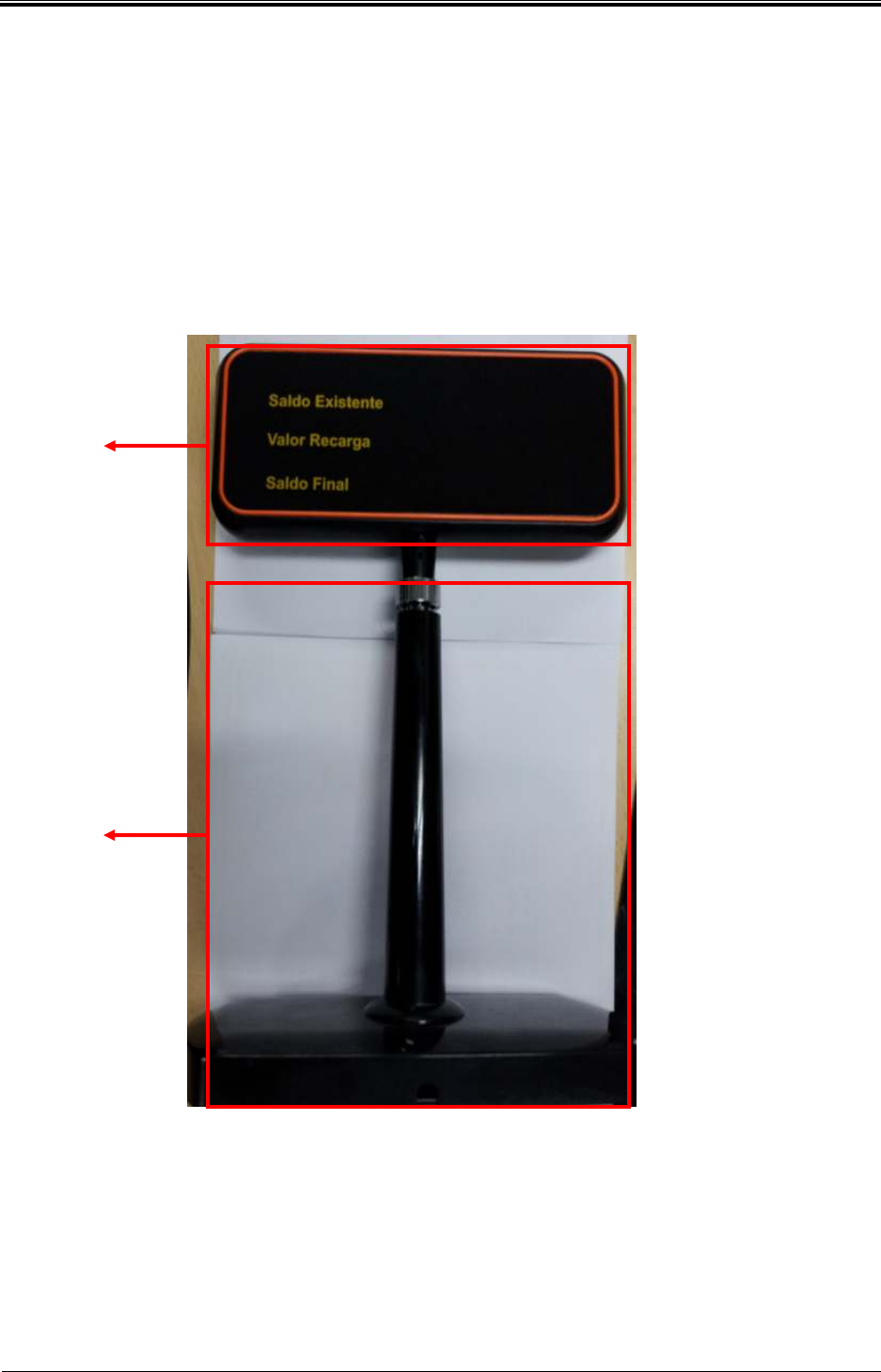
3.2 Customer Display
3.2.1 Outline
Communicate with the attended recharger, display the amount before recharging, the
amounting of recharging, the amount after recharging.
3.2.2 Structure
Customer
Display
Stand
Bogota SIRCI Project
User Requirement Definition
CB-EDR-HM-00-V1.0 Attended Recharger Page
29
of All
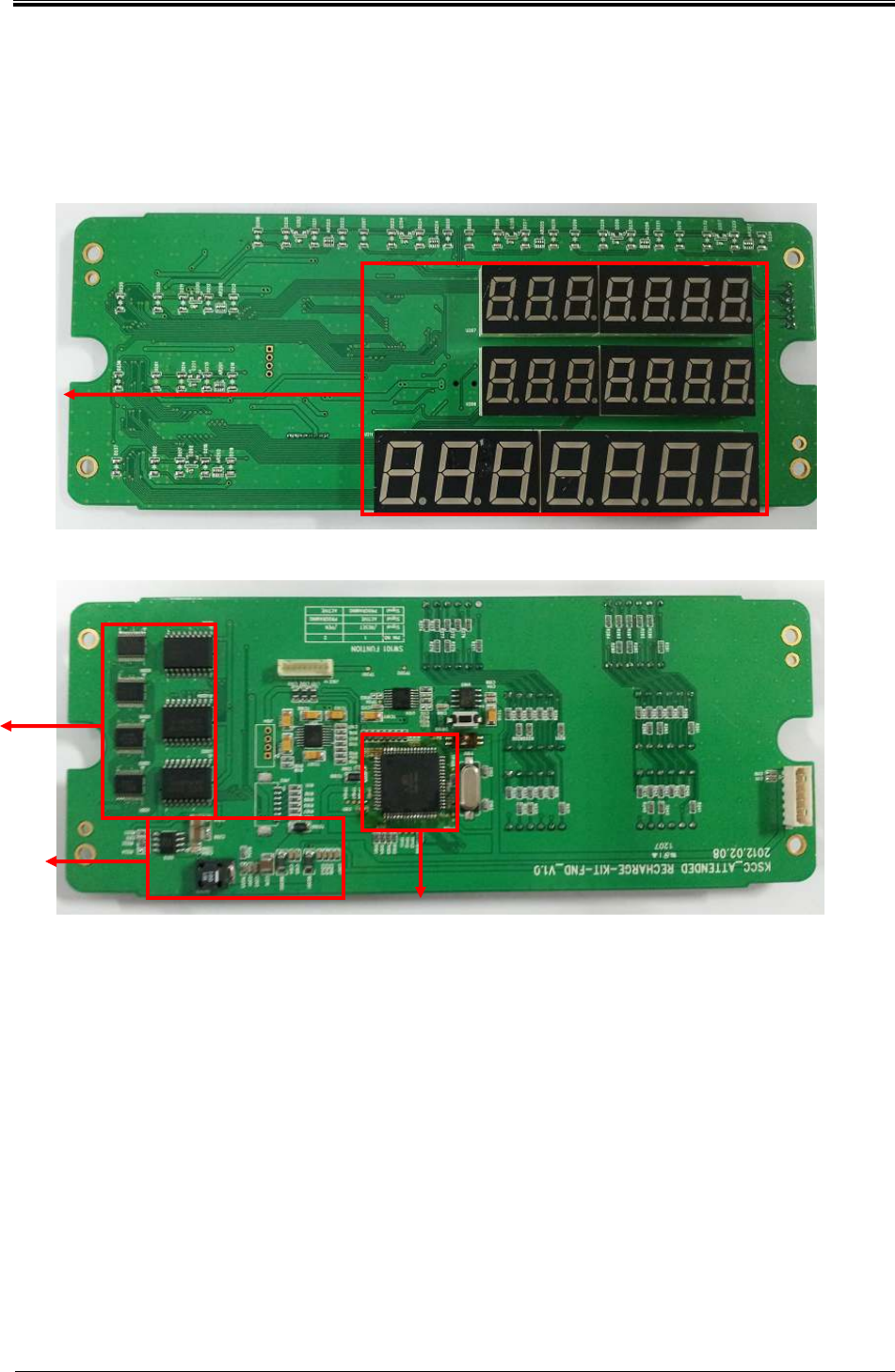
3.2.3 Spec
1) Customer Display Spec
Customer Display communicate with Attended Recharger, display the amount before recharging,
the amount of recharging, the amount after recharging.
CPU
- ATMEGA64A
Power
- Attended Recharger supply DC 12V
Communication
- RS – 232
FND
FND
control
Power
CPU
Bogota SIRCI Project
User Requirement Definition
CB-EDR-HM-00-V1.0 Attended Recharger Page
30
of All
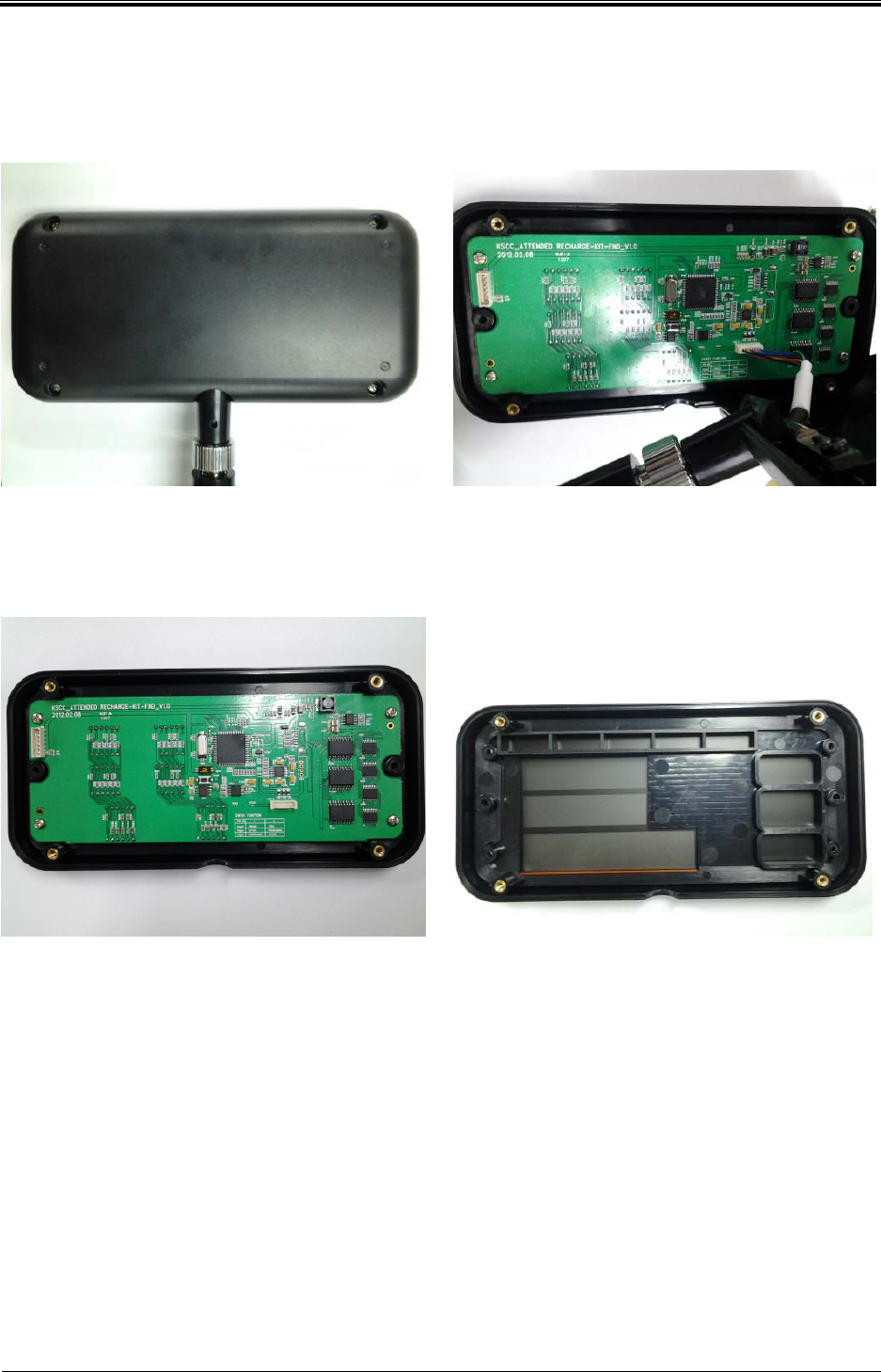
3.2.4 Replacement method
1) Customer Display
<Picture 1> <Picture 2>
A. Picture 1: Loosen 4 fixed bolts, separate back cover.
B. Picture 2: The process of separating back cover, disconnect cable that connected to
connector and separate back cover completely.
<Picture 3> <Picture 4>
A. Picture 3: Loosen 4 fixed bolts and separate PCB completely.
B. Picture 4: When separate completely, PCB and front cover of balance inquiry are
separated completely as shown in the Picture 4 .
C. Assemble is in reverse order.
Bogota SIRCI Project
User Requirement Definition
CB-EDR-HM-00-V1.0 Attended Recharger Page
31
of All
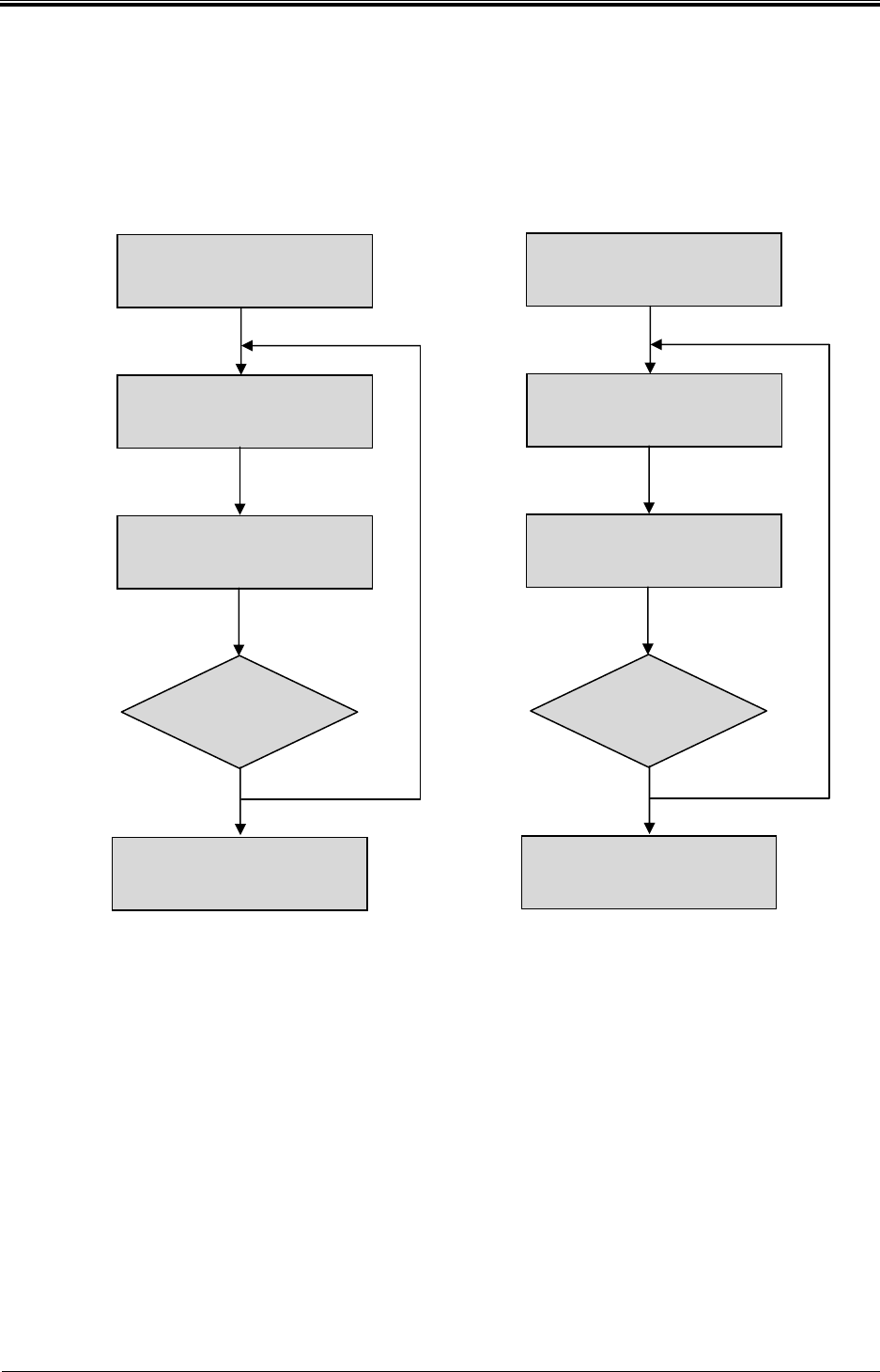
3.3 Maintenance Flow chart
2) Required tool: Driver, tester, etc.
2) Precautions
- Check each part of the adjustment value for every 12months or in a timely
manner.
Conduct
TEST
Error
Check
ERROR CODE
Device maintenance
and replacement due to
MANUAL
Repair complete
OK
NO
Conduct
TEST
Receive replacement
parts
Check maintenance
referral and
ERROR CODE
Device repair due to
MANUAL
Repair com
plete
OK
NO
Bogota SIRCI Project
User Requirement Definition
CB-EDR-HM-00-V1.0 Attended Recharger Page
32
of All
3) Detail check items
No Items
Inspection cycle
Note
1
month
3
months
6
months
1
2months
1 Power/ Voltage check
2 Printer operation check
3 Keypad operation check
4 LCD operation check
5
Customer display
operation check
4. Attended recharger installation and update
4.1 Attended recharger installation
4.1.1 Process
No
Division
C
ontents
N
ote
1
Device
registration
1)
USB mounting method
2) SAM mounting
3
)
P
ower on
… … … …
4.1.2 Device registration
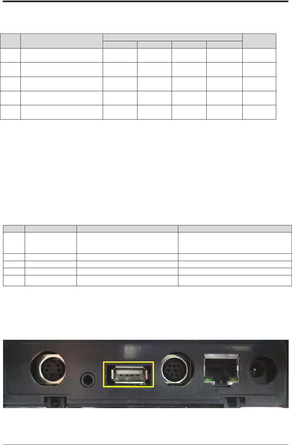
4.1.2.1 USB mounting method
① Turn OFF the terminal.
Bogota SIRCI Project
User Requirement Definition
CB-EDR-HM-00-V1.0 Attended Recharger Page
33
of All
② Insert USB TO USB PORT and turn on.
③ After update, reboot the theminal.
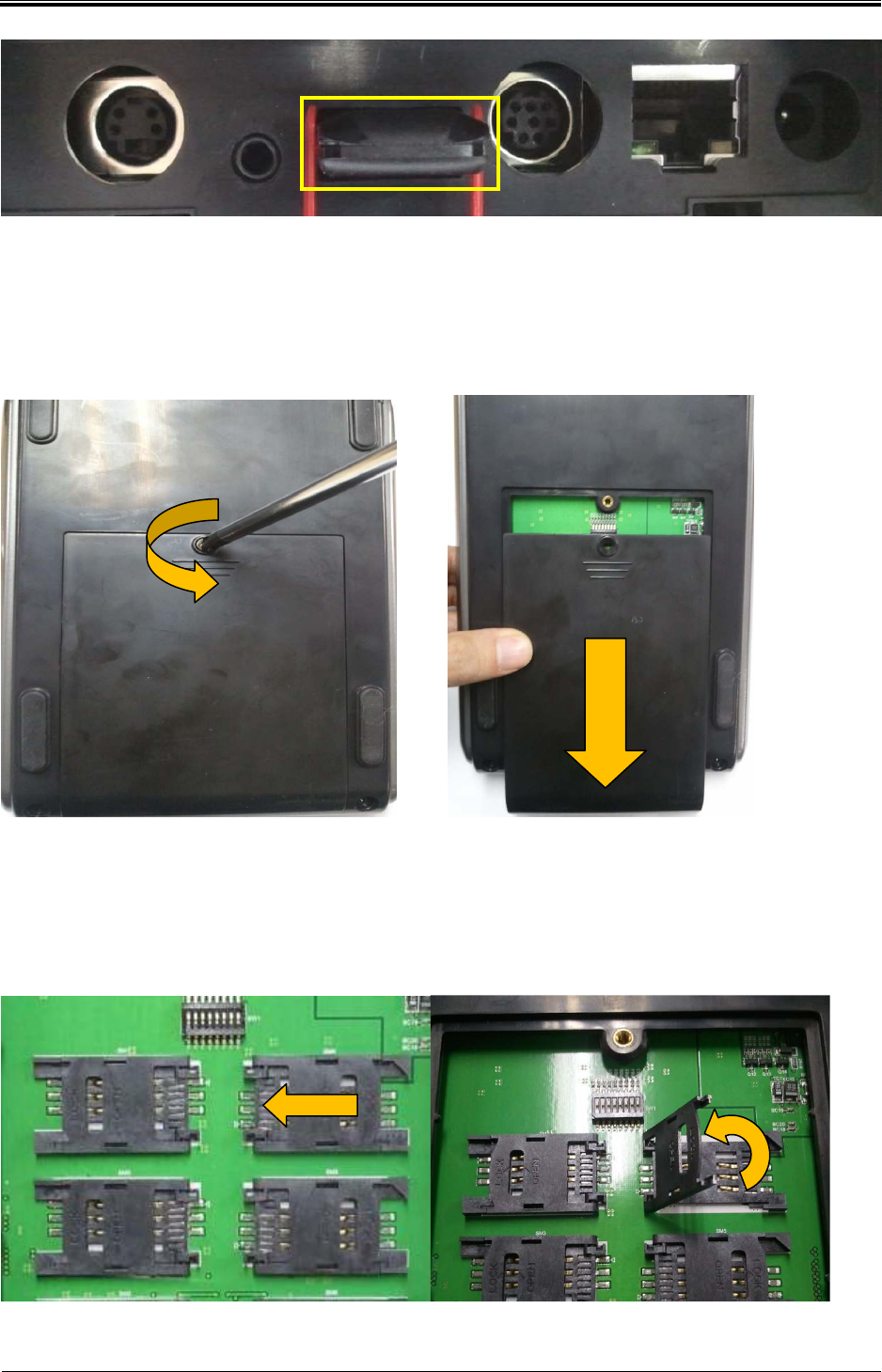
4.1.2.2 SAM Card mounting
< Picture 1 > < Picture 2 >
① Picture 1: Loosen fixed bolts.
② Picture 2: Push in the direction of the arrow and separate completely.
< Picture 3 > < Picture 4 >
Bogota SIRCI Project
User Requirement Definition
CB-EDR-HM-00-V1.0 Attended Recharger Page
34
of All
③ As shown in the Picture 3, push SAM slot in the direction of the arrow and lift SAM
slot like as shown in the Picture 4l
④ After combine the SAM Card, push SAM slot in the direction of the arrow and
secure
⑤ After SAM Card combined, assemble the back case.
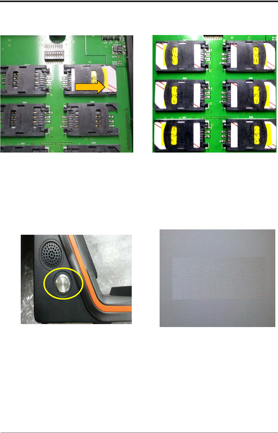
4.1.2.3 Power ON
① Turn on power switch.
② Check T money logo on the screen after booting.
Bogota SIRCI Project
User Requirement Definition
CB-EDR-HM-00-V1.0 Attended Recharger Page
35
of All
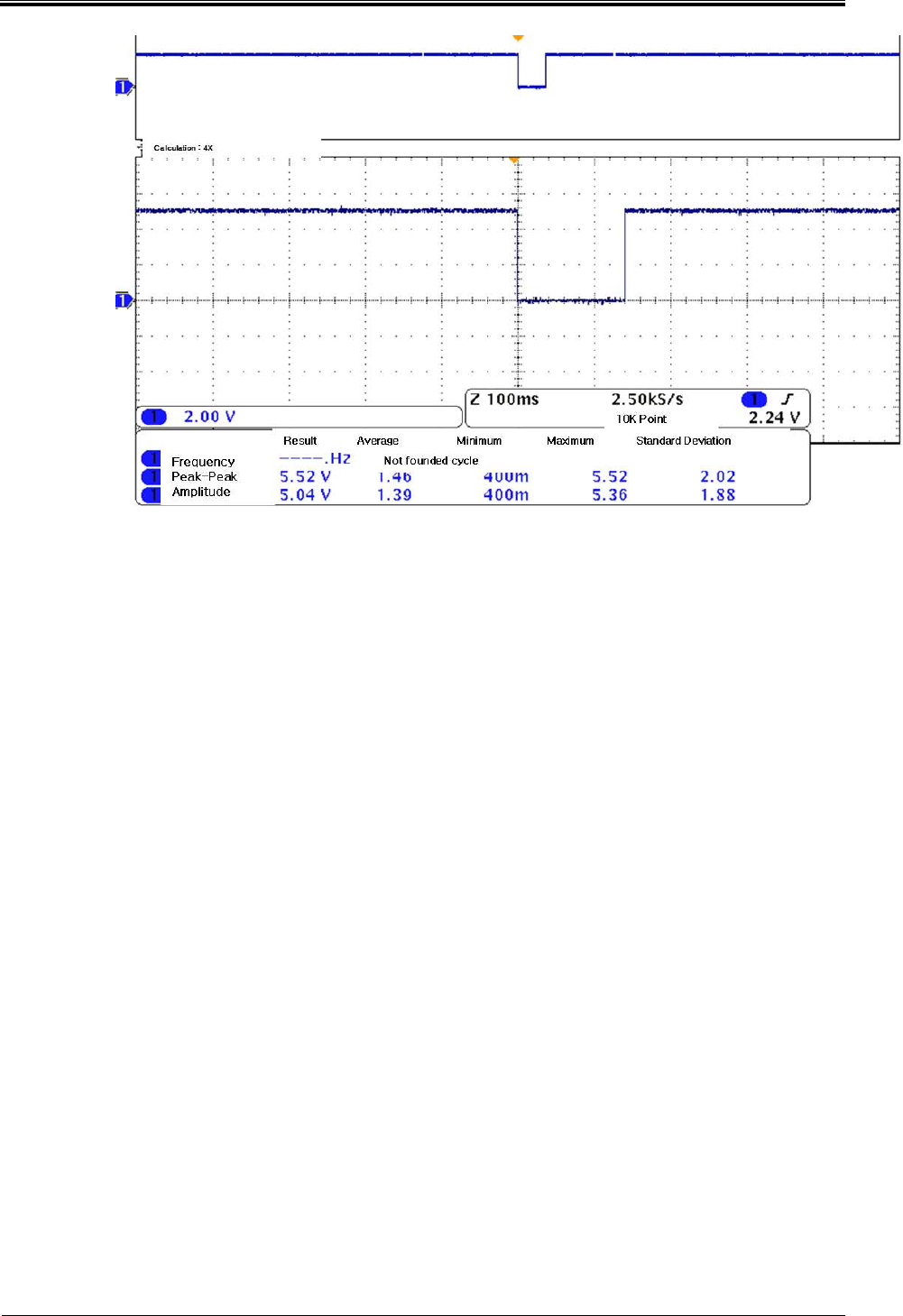
< Normal key input waveform>
Bogota SIRCI Project
User Requirement Definition
CB-EDR-HM-00-V1.0 Attended Recharger Page
36
of All
4.1.3 Sub BOARD spec
4.1.3.1 Sub Main Board spec
Communicate with CPU Board and control I/O device.
Division
Standard
Note
CPU S3C24440
Memory
SDRAM : 128MByte
Nor Flash : 8MByte
N
and Flash : 512 MByte
RF Module ISO 14443 Type A,B
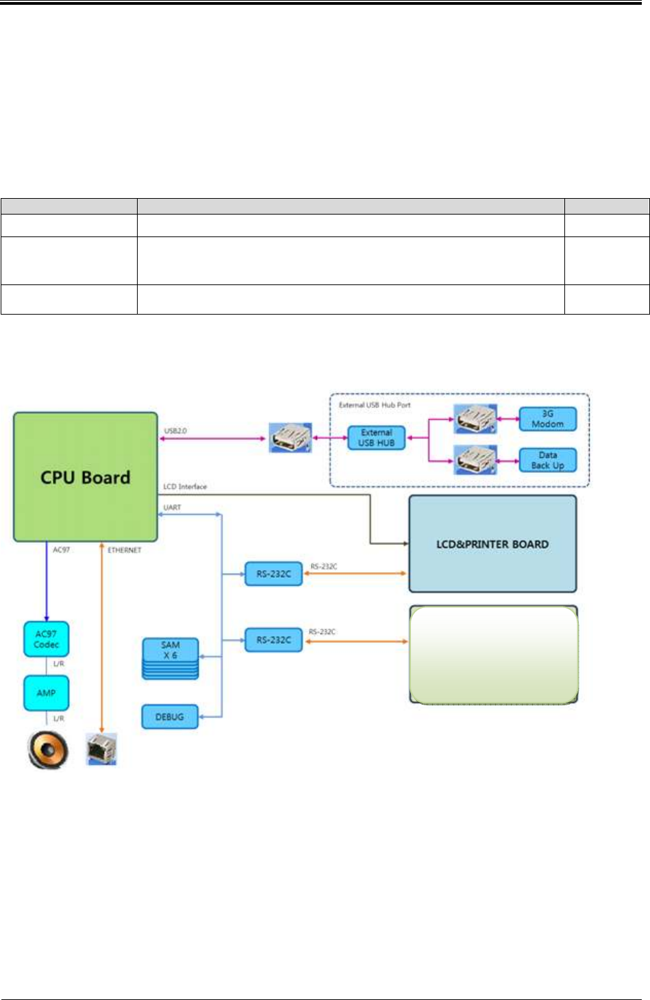
4.1.3.2 Sub Main Board block diagram
Customer
Display board
Bogota SIRCI Project
User Requirement Definition
CB-EDR-HM-00-V1.0 Attended Recharger Page
37
of All
4.1.3.3 Sub Main I/O
- RS-232
PRIN T_DTR[3]
12
3
J14
5749181-1(DIN_CON)
TX_DI SP
1
RX_DISP
2
GND
3
GND
4
5
6
<J8 Pin Assign>
4
<2011.12.9
>
- NET
(CUSTOM_232_TX/CUSTOM_232_RX)
Spare RS-232C / PRINTER MODULE
* SELECTION Of PRINT 232-LEVEL
21
3
<J14 Pin Assign>
4
J8
5749267-1(DIN_CON)
12V_DISP
1
12V_DISP
2
12V_DISP
3
TX_DI SP
4
RX_DISP
5
GND
6
GND
7
GND
8
CUSTOM_RX[3]
VDD_3.3V
TC3
10uF/16V
TC-3216-A
12
CUSTOM_TX[3]
VDD_3.3V
R91 1K R -1005
R88 100R R-1005
R95 1K R-1005
R90 100R R-1005
C39 100nF
C-1005
CPU DEBUGER
DBG_TX[3] DBG_TX
DBG_RX[3] DBG_RX
J7
TSH-3813
STEREO-JACK-SH381D -PA9T-A
2
3
1
C37 100nF
C-1005
R316 100R
C38 100nF
C-1005
R86 100R R-1005
R92 100R R-1005
R87 1K R -1005
C36 100nF
C-1005
R93 1K R-1005
U9
SP3232EY
TSSOP16
C1+
1
C1-
3
C2+
4
C2-
5
T1IN
11
T2IN
10
R1OUT
12
R2OUT
9
GND
15
T1OUT 14
T2OUT 7
R1IN 13
R2IN 8
VCC 16
V- 6
V+ 2
R89 100R R-1005
R94 100R R-1005
CUSTOM_232_RX
C40 100nF
C-1005
CUSTOM_232_TX
Customer Display RS-232C
12V_DISP
J9
SMW200-5P
SMW200-05
1
2
3
4
5
RR500 100R R-1005
C44 100nF
C-1005
R97 33R R -1005
C42 100nF
C-1005
R98 100R R-1005
PRIN T_232_RX
R102 100R R-1005
PRI NT_RX
PRI NT_TX
R96 100R R-1005
U10
SP3232EY
TSSOP16
C1+
1
C1-
3
C2+
4
C2-
5
T1IN
11
T2IN
10
R1OUT
12
R2OUT
9
GND
15
T1OUT 14
T2OUT 7
R1IN 13
R2IN 8
VCC 16
V- 6
V+ 2
R103 33R R-1005
R101 33R R-1005
C45 100nF
C-1005
C43 100nF
C-1005
+
EC7
10uF/16V
TC-3216-A
R100 100R R-1005
R99 33R R -1005
C41 100nF
C-1005
VDD_3.3V
PRIN T_232_TX
VDD_3.3V
PRI NT_TX[3]
EXT-UAR T_TX
EXT-UAR T_RX
PRI NT_RX[3]
R106 Z_100R
R107 Z_100R
PRIN T_TX
DECO_LED #1[3]
PRIN T_RX
PRI NT_232_TX R104 100R
PRI NT_232_RX R105 100R
<2011.12.9
>
- J9
(3P->5P)
- RR500(1005)
, NET
78
<2011.12.10
>
Spare RS-232C
① Circuit desctiprion
: Circuis that change UART signal into RS -232 signal
② Waveform measurements
<Normal TX waveforms>
Bogota SIRCI Project
User Requirement Definition
CB-EDR-HM-00-V1.0 Attended Recharger Page
38
of All
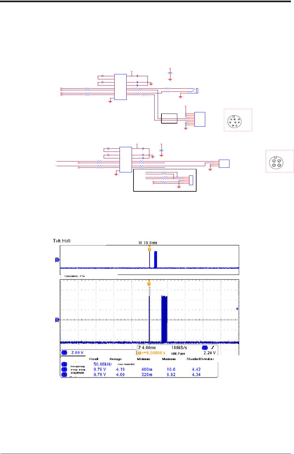
<Normal RX waveforms>
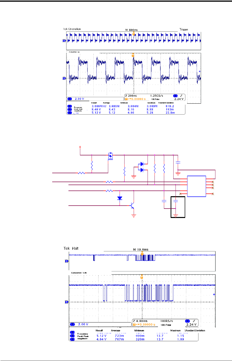
- SIM Part (Clock)
SAM5.0VSAM5.0V
SIM_CLK2
R201
1K
R-1608
C86
100nF
C-1608
1 2
Y3
3.6864MHz(SCO-105)
VCC
4
OUT 3
GND
2
SAM5.0VSAM5.0V
C47
100nF
C-1608
1 2
SIM_CLK1
Y1
3.6864MHz(SCO-105)
VCC
4
OUT 3
GND
2
R124
1K
R-1608
R1002
Z_0R
R-1608
R1003 0R R-1608
① Circuit description
: Circuit that supply the stable Clock to allow SIM Card to operate.
Bogota SIRCI Project
User Requirement Definition
CB-EDR-HM-00-V1.0 Attended Recharger Page
39
of All
② Waveform measurements
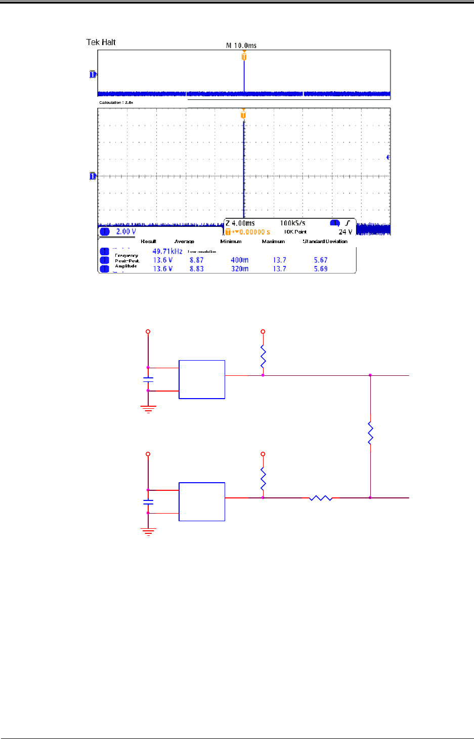
<Normal Clock waveform>
- SIM Part (Signal)
GND
R125
10K
R-1608
C50
30pF
C-1608
R136 100R R-1608
Q3
Z_MMBT3904(SOT-23)
1
2 3
C48
100nF
C-1608
R129 1K
R-1608
R126
10K
D4
SD103B(SOD123)
12
R127
1K
R-1608
Q1
SI2301DS(SOT-23)
1
32
R128
1K
R-1608
3
1
2
ZD1
Z_L16513
SIM_PWR_ON1_5V
SAM5.0V
SIM_RX1_A
SIM SOCKET #1
SIM_RESET_ON1_5V
SIM_TX1_A
R134 100R
R-1608
SIM_CLK1
SM1
DRC017S
VCC
1
RST
2
CLK
3FU1 4
GND 5
VPP 6
SIO
7FU2 8
S1
9S2 10
C51
Z_10pF
C-1608
① Circuit description
: Circuit that realize to recognize SIM CARD .
② Waveform measurements
<Waveform when normally recognize SIM CARD>

Bogota SIRCI Project
User Requirement Definition
CB-EDR-HM-00-V1.0 Attended Recharger Page
40
of All
FCC Statement
This device complies with Part 15 of the FCC Rules. Operation is subject to the following two
conditions:
(1) This device may not cause harmful interference. and
(2) This device must accept any interference received, including interference that may cause
undesired operation.
Any changes or modifications to the equipment not expressly approved by the party responsible for
compliance could void the user's authority to operate the equipment.
Note: This equipment has been tested and found to comply with the limits for a Class B digital device,
pursuant to part 15 of the FCC Rules. These limits are designed to provide reasonable protection against
harmful interference in a residential installation.
This equipment generates, uses and can radiate radio frequency energy and, if not installed and used in
accordance with the instructions, may cause harmful interference to radio communications. However,
there is no guarantee that interference will not occur in a particular installation. If this equipment does
cause harmful interference to radio or television reception, which can be determined by turning the
equipment off and on, the user is encouraged to try to correct the interference by one or more of the
following measures:
—Reorient or relocate the receiving antenna.
—Increase the separation between the equipment and receiver.
—Connect the equipment into an outlet on a circuit different from that to which the receiver is connected.
—Consult the dealer or an experienced radio/TV technician for help.
.