LG CNS KSCCCBR400A AUTOMATIC RECHARGER User Manual Manual
LG CNS CO., LTD. AUTOMATIC RECHARGER Manual
UserManual.wiki
>
LG CNS
>
KSCCCBR400A User Manual
Users Manual
Navigation menu
Upload a User Manual
Namespaces
Wiki Guide
HTML
PDF
Info
Views
User Manual
Discussion / Help
Navigation
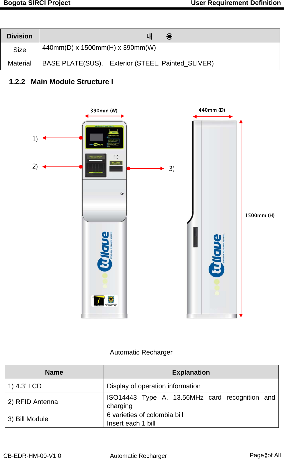
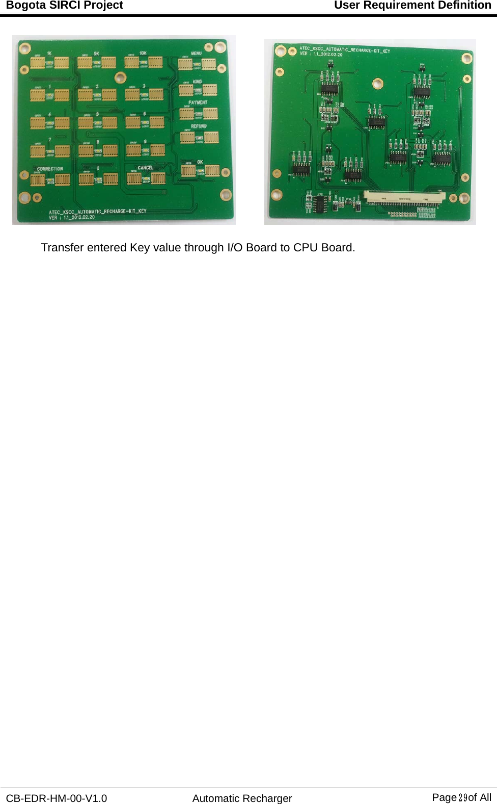
![Bogota SIRCI Project User Requirement Definition CB-EDR-HM-00-V1.0 Automatic Recharger Page1 of All 1. Automatic Recharger Equipment Structure 1.1 Overview The Automatic Recharger is recharged the transit card. 1.2 External / Internal Structure and Main Module 1.2.1 External Structure [Automatic Recharger] 390mm (W) 440mm (D) 1500mm (H)](https://usermanual.wiki/LG-CNS/KSCCCBR400A/User-Guide-1705167-Page-6.png)
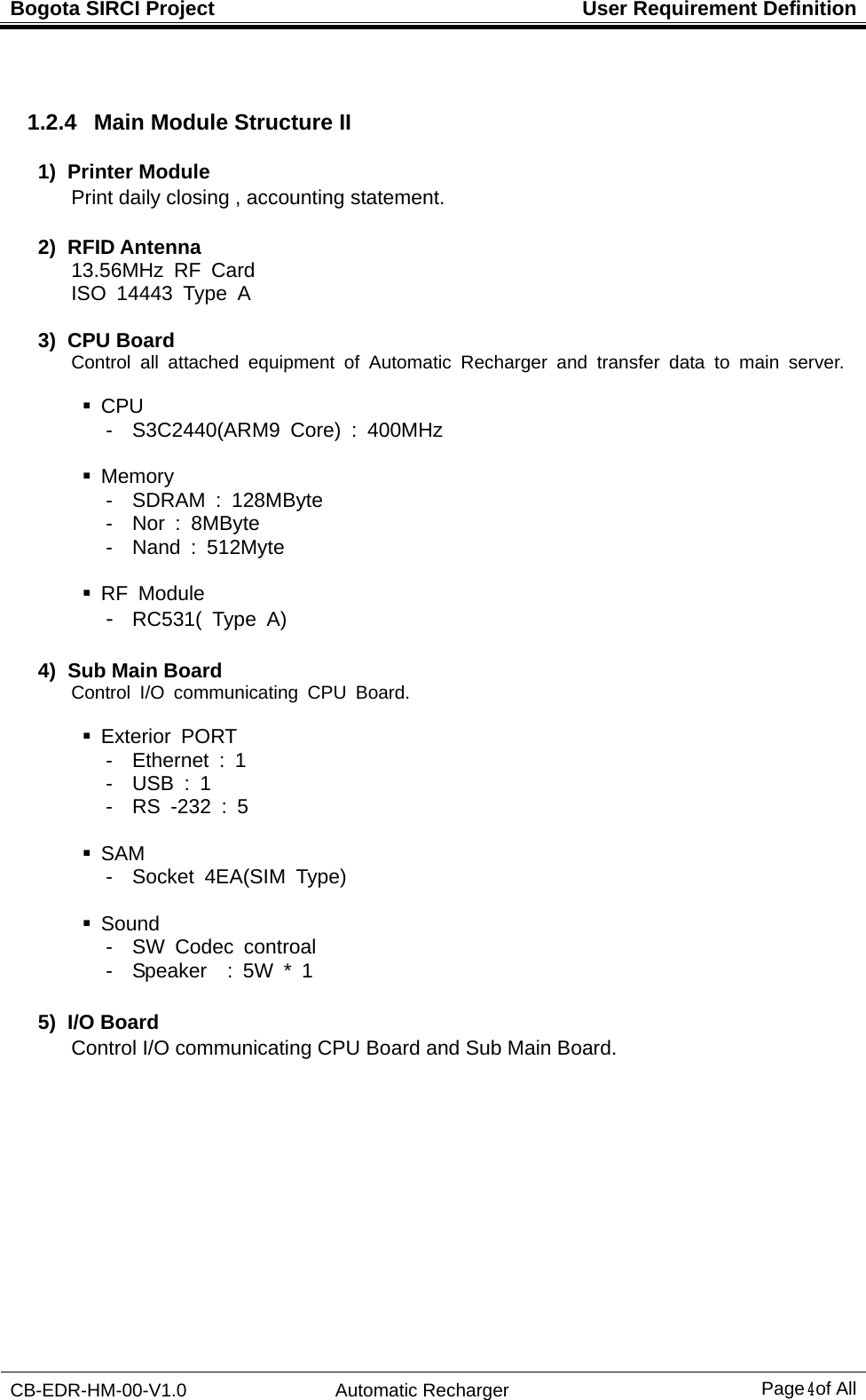

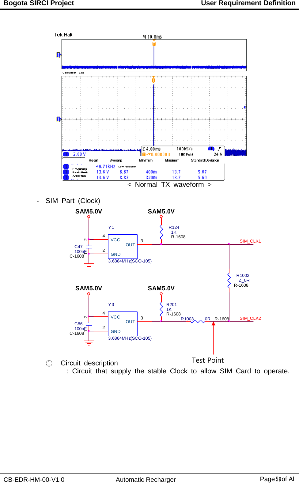
![Bogota SIRCI Project User Requirement Definition CB-EDR-HM-00-V1.0 Automatic Recharger Page58 of All 5.1.2.3 Sub Main Check point - RS-232 ③ Circuit description : Change UART signal into RS -232 signal ④ Waveform measurements < Normal TX waveform > CUSTOM_RX[3]VDD_3.3VTC310uF/16VTC-3216-A12CUSTOM_TX[3]VDD_3.3VR91 1K R-1005 R88 100R R-1005R95 1K R-1005R90 100R R-1005C39 100nFC-1005CPU DEBUGERDBG_TX[3] DBG_TXDBG_RX[3] DBG_RXJ7TSH-3813STEREO-JACK-SH381D-PA9T-A231C37 100nFC-1005C38 100nFC-1005R86 100R R-1005R92 100R R-1005R87 1K R-1005C36 100nFC-1005R93 1K R-1005U9SP3232EYTSSOP16C1+1C1-3C2+4C2-5T1IN11T2IN10R1OUT12R2OUT9GND15T1OUT 14T2OUT 7R1IN 13R2IN 8VCC 16V- 6V+ 2R89 100R R-1005R94 100R R-1005C40 100nFC-1005TX Test Point RX Test Point](https://usermanual.wiki/LG-CNS/KSCCCBR400A/User-Guide-1705167-Page-63.png)