LG CNS XID500 RFID Card Reader User Manual
LG CNS CO., LTD. RFID Card Reader Users Manual
UserManual.wiki
>
LG CNS
>
XID500 User Manual
Users Manual
Navigation menu
Upload a User Manual
Namespaces
Wiki Guide
HTML
PDF
Info
Views
User Manual
Discussion / Help
Navigation


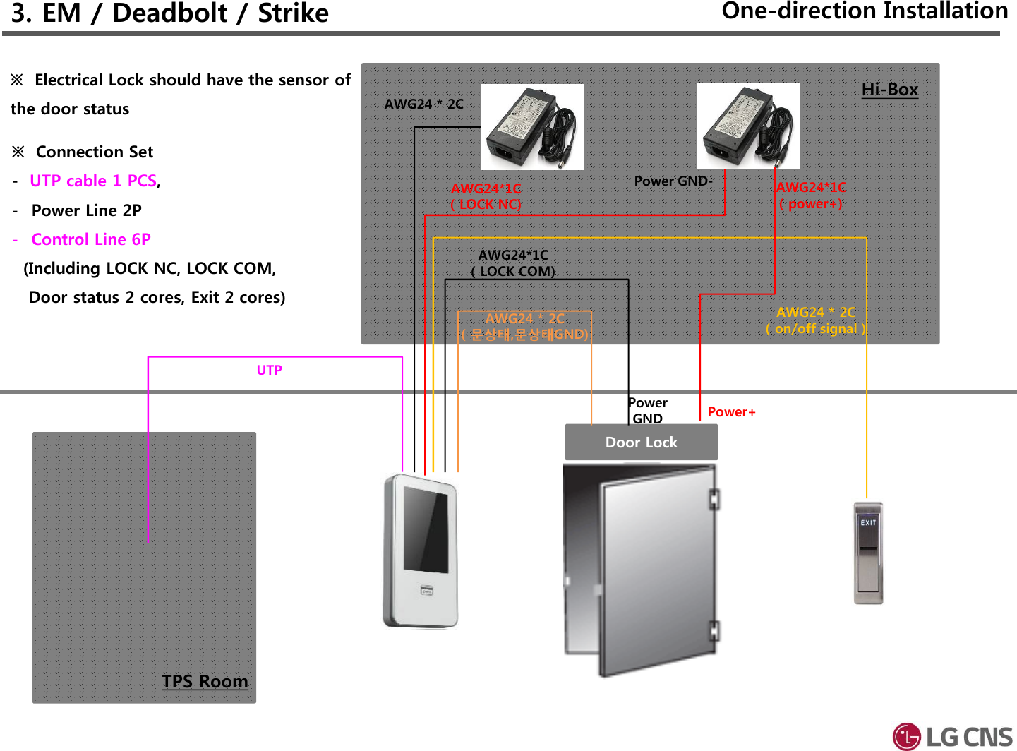
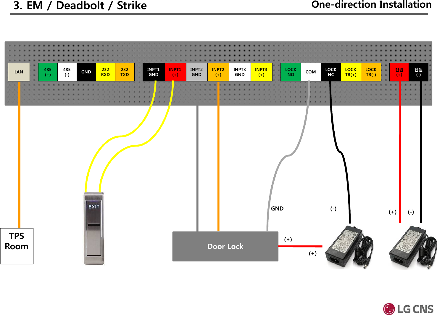
![3. EM / Deadbolt / Strike[Manager] > [Controller]Set to “단말기 해체 경보음”In/Out : Set on the specific purpose [Manager] > [LCM]LCM유형 : NoneDoorLock 설정 : Set on purpose of Lock typeInput#1(InsideOpen) : NOInput#2(Door Status) : Set on purpose of the status door typeInput#3(Lock Status) : None[Operation Mode]Set to “출입”One-direction Installation](https://usermanual.wiki/LG-CNS/XID500/User-Guide-3656602-Page-11.png)

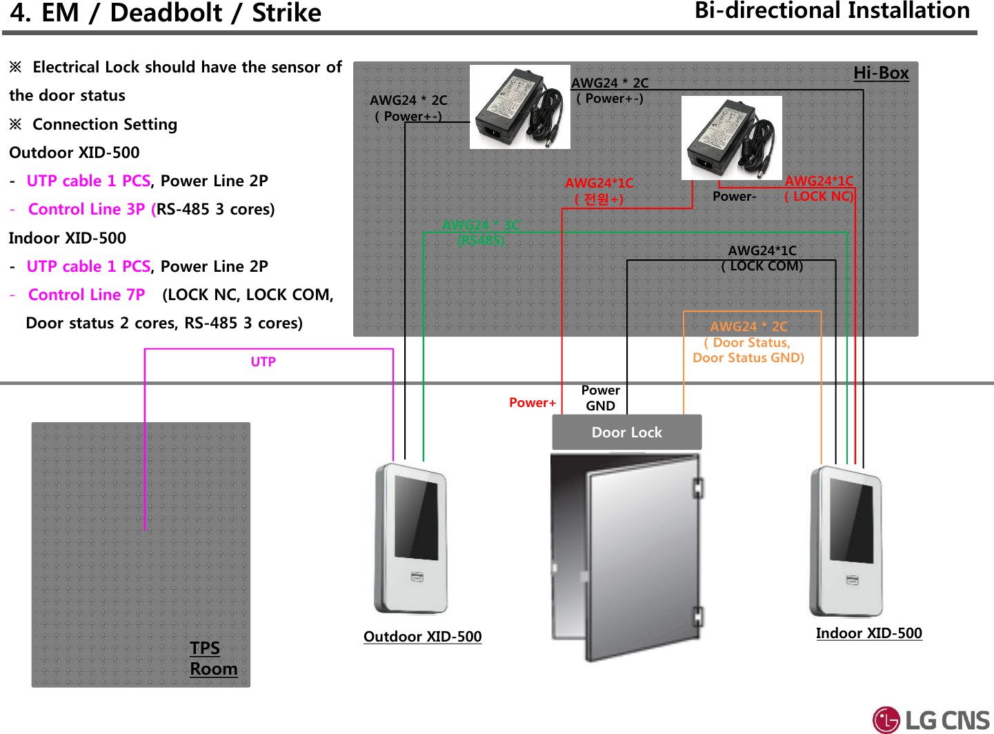
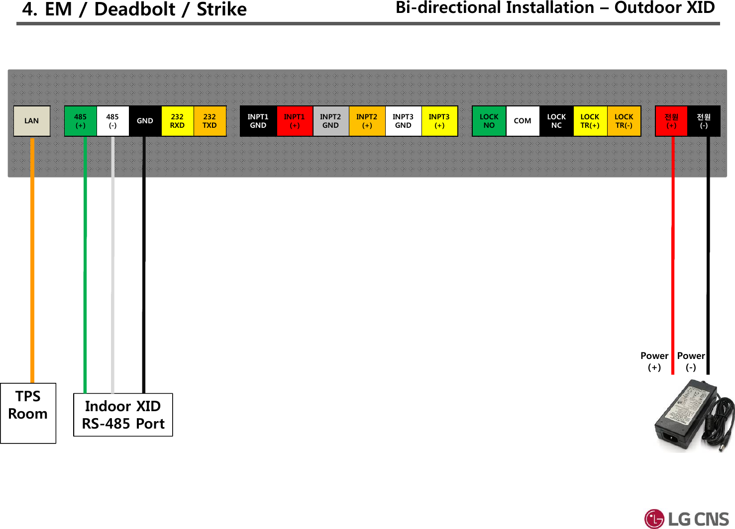
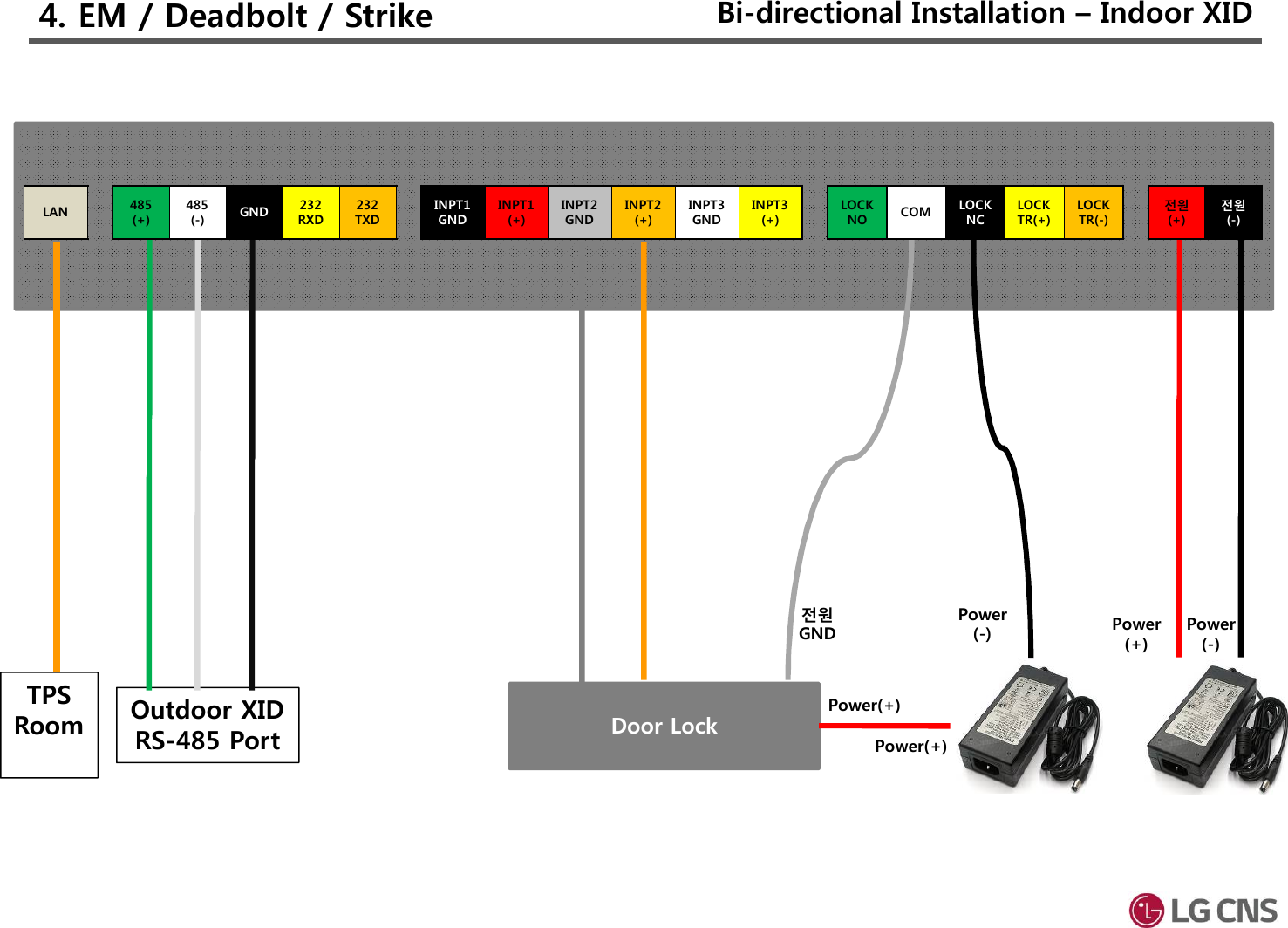
![4. EM / Deadbolt / Strike[기기관리] > [기기제어] [기기관리] > [LCM][운용]Set to “출입” Set to “단말기 해체 경보음”In/Out : Set on the direction purposeSet to “RS485 In/Out” Make a role “Master/Slave” LCM Type : NoneDoorLock 설정 : Set on purpose of Lock typeInput#1(InsideOpen) : NoneInput#2(Door Status) : Set on purpose of the status door typeInput#3(Lock Status) : NoneBi-direction Installation](https://usermanual.wiki/LG-CNS/XID500/User-Guide-3656602-Page-18.png)

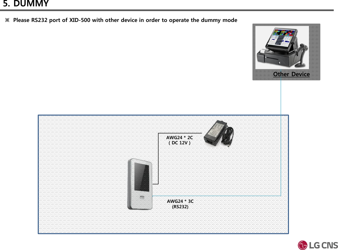
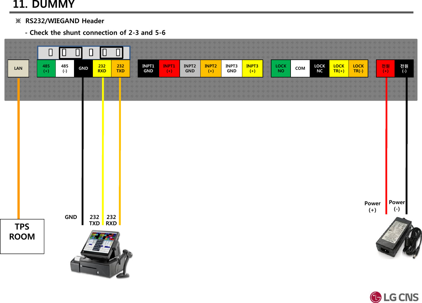
![[운용] [운용] > [Customize] > [Dummy설정]11. DUMMY Dummy InstallationSet to “Dummy” Dummy Type : RS232Select the type of message(Message, Card number) Confirm output mode](https://usermanual.wiki/LG-CNS/XID500/User-Guide-3656602-Page-23.png)
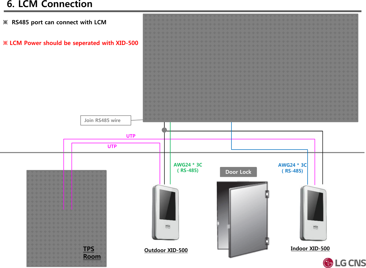
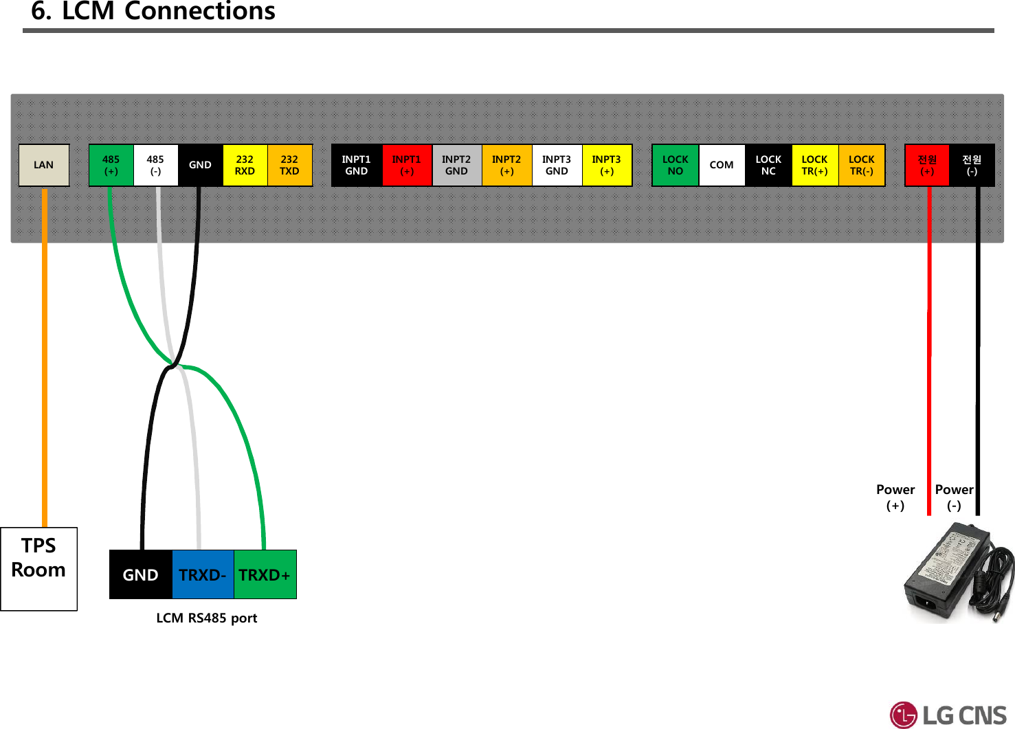
![[기기관리] > [기기제어] [기기관리] > [LCM][운용]InstallationSet “운용모드” to “출입” Set to “단말기 해체 경보음”In/Out : Set on the direction purposeLCM Type : XID3.0DoorLock 설정 : NoneInput#1(InsideOpen) : NoneInput#2(Door Status) : NO or NCInput#3(Lock Status) : None6. LCM Connections](https://usermanual.wiki/LG-CNS/XID500/User-Guide-3656602-Page-27.png)