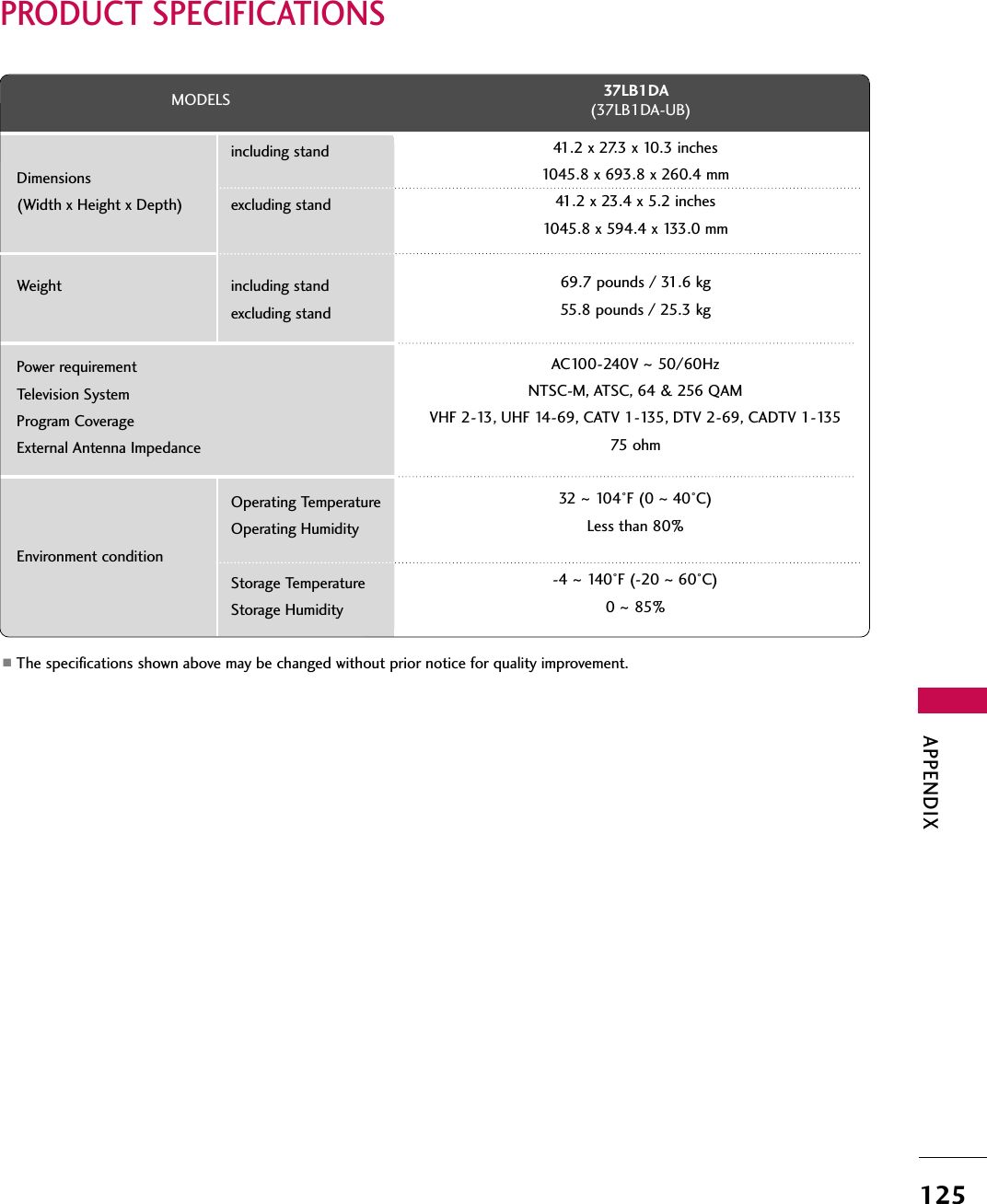
LG Electronics USA 37LDB 37" LCD TV MONITOR User Manual User s Manual H ok

LG Electronics USA 37" LCD TV MONITOR User s Manual H ok

USERS MANUAL

   EUT Type: 37” LCD TV/Monitor FCC ID: BEJ37LDB Test Report No.: GETEC-E3-06-004 FCC Class B Certification   APPENDIX H : USER’S MANUAL
37LB1DAP/NO : 38289U0512F (0601-REV00)
WARNING  / CAUTION1WARNING  / CAUTIONWARNING / CAUTIONTo prevent fire or shock hazards, do not exposethis product to rain or moisture.FCC NOTICEClass B digital deviceThis equipment has been tested and found to com-ply with the limits for a Class B digital device, pur-suant to Part 15 of the FCC Rules. These limits aredesigned to provide reasonable protection againstharmful interference in a residential installation. Thisequipment generates, uses and can radiate radio fre-quency energy and, if not installed and used inaccordance with the instructions, may cause harmfulinterference to radio communications. However,there is no guarantee that interference will notoccur in a particular installation. If this equipmentdoes cause harmful interference to radio or televi-sion reception, which can be determined by turningthe equipment off and on, the user is encouraged totry to correct the interference by one or more ofthe following measures:- Reorient or relocate the receiving antenna.- Increase the separation between the equipmentand receiver.- Connect the equipment to an outlet on a circuitdifferent from that to which the receiver is con-nected.- Consult the dealer or an experienced radio/TVtechnician for help.Any changes or modifications not expresslyapproved by the party responsible for compliancecould void the user’s authority to operate theequipment. CAUTIONDo not attempt to modify this product in any waywithout written authorization from LG Electronics.Unauthorized modification could void the user’sauthority to operate this product The lightning flash with arrowhead sym-bol, within an equilateral triangle, isintended to alert the user to the pres-ence of uninsulated “dangerous voltage” withinthe product’s enclosure that may be of sufficientmagnitude to constitute a risk of electric shockto persons.The exclamation point within an equi-lateral triangle is intended to alert theuser to the presence of importantoperating and maintenance (servicing) instruc-tions in the literature accompanying the appli-ance.TO REDUCE THE RISK OF ELECTRIC SHOCKDO NOT REMOVE COVER (OR BACK). NOUSER SERVICEABLE PARTS INSIDE. REFER TOQUALIFIED SERVICE PERSONNEL.WARNING/CAUTIONTO REDUCE THE RISK OF FIRE AND ELECTRICSHOCK, DO NOT EXPOSE THIS PRODUCT TORAIN OR MOISTURE.
SAFETY INSTRUCTION2IMPORTANT SAFETY INSTRUCTIONSSAFETY INSTRUCTIONRead these instructions.Keep these instructions.Heed all warnings.Follow all instructions.Do not use this apparatus near waterClean only with dry cloth.Do not block any ventilation openings. Install inaccordance with the manufacturer’s instructions.Do not install near any heat sources such asradiators, heat registers, stoves, or other appa-ratus (including amplifiers)that produce heat.Do not defeat the safety purpose of thepolarized or grounding-type plug. A polarizedplug has two blades with one wider than theother. A grounding type plug has two bladesand a third grounding prong, The wide bladeor the third prong are provided for your safe-ty. If the provided plug does not fit into youroutlet, consult an electrician for replacementof the obsolete outlet.Protect the power cord from being walked onor pinched particularly at plugs, conveniencereceptacles, and the point where they exitfrom the apparatus.Only use attachments/accessories specifiedby the manufacturer.Important safety instructions shall be provided with each apparatus. This information shall be given in a separatebooklet or sheet, or be located before any operating instructions in an instruction for installation for use andsupplied with the apparatus. This information shall be given in a language acceptable to the country where the apparatus is intended tobe used. The important safety instructions shall be entitled “Important Safety Instructions”. The following safetyinstructions shall be included where applicable, and, when used, shall be verbatim as follows. Additional safetyinformation may be included by adding statements after the end of the following safety instruction list. Atthe manufacturer’s option, a picture or drawing that illustrates the intent of a specific safety instruction maybe placed immediately adjacent to that safety instruction :Owner's Manual1234567
SAFETY INSTRUCTION3Use only with the cart, stand, tripod, bracket,or table specified by the manufacturer, or soldwith the apparatus. When a cart is used, usecaution when moving the cart/apparatuscombination to avoid injury from tip-over.Unplug this apparatus during lightning stormsor when unused for long periods of time.Refer all servicing to qualified service person-nel. Servicing is required when the apparatushas been damaged in any way, such as power-supply cord or plug is damaged, liquid hasbeen spilled or objects have fallen into theapparatus, the apparatus has exposed to rainor moisture, does not operate normally, orhas been dropped.CAUTION concerning the Power Cord :Most appliances recommend they be placedupon a dedicated circuit; that is, a single out-let circuit which powers only that applianceand has no additional outlets or branch cir-cuits. Check the specification page of thisowner's manual to be certain.Do not overload wall outlets. Overloaded walloutlets, loose or damaged wall outlets, exten-sion cords, frayed power cords, or damagedor cracked wire insulation are dangerous. Anyof these conditions could result in electricshock or fire. Periodically examine the cord ofyour appliance, and if its appearance indicatesdamage or deterioration, unplug it, discontinueuse of the appliance, and have the cordreplaced with an exact replacement part by anauthorized servicer. Protect the power cordfrom physical or mechanical abuse, such asbeing twisted, kinked, pinched, closed in adoor, or walked upon. Pay particular attentionto plugs, wall outlets, and the point where thecord exits the appliance.Outdoor Use Marking :WARNING - To Reduce The Risk Of Fire OrElectric Shock, Do Not Expose This ApplianceTo Rain Or MoistureWet Location Marking : Apparatus shall notbe exposed to dripping or splashing and noobjects filled with liquids, such as vases, shallbe placed on or over apparatus.8910111213
INTRODUCTION9ACCESSORIESEnsure that the following accessories are included with your plasma display. If an accessory is missing, pleasecontact the dealer where you purchased the product.Owner's ManualOwner’s Manual BatteriesMENUINFO   iTV GUIDEENTEREXITSAPCCRATIOPOWERDAY -DAY+VCRTVDVDAUDIOCABLESTBMODETV INPUTINPUTRemote Control Power CordD-sub 15 pin Cable 75ohm Round CableCable Management(Refer to p.15)Twister HolderArrange the wires with the twister holder.2-TV Brackets, 2-Wall Brackets2-TV Bracket Bolts
INTRODUCTION10INTRODUCTIONCONTROLSThis is a representation of the front panel of models 37LB1DA TVs.■Here shown may be somewhat different from your TV.Front Panel ControlsCHVOLMENUINPUTTV GUIDEPOWERButtonTVGUIDEButtonINPUTButtonMENUButtonVOLUME(FF,GG)ButtonsCHANNEL(EE,DD)ButtonsCHVOLMENUINPUTTV GUIDERemote Control SensorPower Standby IndicatorIlluminates red in standby mode.When the TV is turned on, the indicatorblinks white and then illuminates whitebefore the picture is displayed.INDEXInserting the CableCARDs.HDTV modeAV modeComponent modeRGB-PC modeHDMI1/DVI or HDMI2 mode
INTRODUCTION11CONNECTION OPTIONBack Connection PanelS-VIDEOVIDEO AUDIOAV IN 2Cable CARDCable CARDL/MONO RHDMI INDIGITAL AUDIO OUTOPTICALRS-232C IN(CONTROL & SERVICE)AUDIO IN(RGB/DVI)COMPONENT INVIDEOAUDIOVIDEOAUDIO(            )S-VIDEOAV IN 1AV OUTANTENNAINCABLEINREMOTECONTROL RGB IN (PC/DTV)HDMI INHDMI INDIGITAL AUDIO DIGITAL AUDIO OUTOUTOPTICALPTICALRS-232C INRS-232C IN(CONTROL(CONTROL & SERVICE)SERVICE)AUDIO INAUDIO IN(RGB/DVI)(RGB/DVI)COMPONENT INCOMPONENT INVIDEOVIDEOAUDIOAUDIOVIDEOVIDEOAUDIOAUDIOMONO(                        )S-VIDEOS-VIDEOAV IN 1AV IN 1AV OUTAV OUTANTENNAANTENNAININCABLECABLEININREMOTEREMOTECONTROL CONTROL RGB INRGB IN (PC (PC/DTV)DTV)S-VIDEO InputProvides better picture quality than thevideo input.AUDIO InputConnections are available for listening tostereo sound from an external device.VIDEO InputConnects the video signal from a videodevice.CableCARD™Used for CableCARD™Cable Service Provider.This is a back panel of 37LB1DA.AV OUTConnect a second TV or monitor.AV (Audio/Video) IN 1  Connect  audio/video  output  from  an  externaldevice to these jacks.S-VIDEO Connect S-Video out from an S-VIDEO device.COMPONENT INConnect a component video/audio device to thesejacks.HDMI INConnect a HDMI signal to 1(DVI) or 2.Or DVI(VIDEO)signal to the 1(DVI) port with a DVIto HDMI cable.DIGITAL AUDIO OUTConnect digital audio from various types of equipment. Note: In standby mode, these ports do not work.RS-232C IN (CONTROL & SERVICE) PORTConnect to the RS-232C port on a PC.ANTENNA INConnect over-the air signals to this jack.CABLE INConnect cable signals to this jack.RGB/AUDIO INConnect  the  monitor  output  from  a  PC  to  theappropriate input port.Remote Control PortConnect your wired remote control.Power Cord SocketFor operation with AC power. Caution: Never attempt to operate the TV on DC power.101241 67891023455 67839
INSTALLATION 14TO ATTACH THE TV TO A WALLINSTALLATION We recommend that you set up the TV close to a wall so it cannot fall over if pushed backwards. Additionally, we recommend that the TV be attached to a wall so it cannot be pulled in a forward direction, poten-tially causing injury or damaging the product. Caution: Please make sure that children don’t climb on or hang from the TV. ■Insert the eye-bolts (or TV brackets and  bolts) to tighten the product to the wall as shown in the picture. *If your TV have bolts in the upper holes, loosen the bolts.Insert the eye-bolts and tighten them securely in the upper holes.Secure the wall brackets with the bolts (not provided as parts of the product, must purchase separately ) onthe wall. Match the height of the bracket that is mounted on the wall to the holes in the product.Ensure the eye-bolts or brackets are tightened securely.■Use a sturdy rope (not provided as parts of the product, must purchase sep-arately) to tie the product. It is safer to tie the rope so it becomes horizon-tal between the wall and the product.
INSTALLATION 15WIRE ARRANGEMENTThis function explains the features available on the 37LB1DA.Connect the cables as necessary.After connecting the cables neatly, arrange the cables to the Cable Holder.To connect an additional equipment, see the External equipment Connections section.Install the CABLE MANAGEMENT as shown.How to remove the CABLEMANAGEMENTGGHold the CABLE MANAGEMENTwith both hands and pull it backward.CABLE MANAGEMENTGGDo not hold the CABLE MANAGEMENTwhen moving the product.- If the product is dropped, you may beinjured or the product may be broken.NOTE!CABLE HOLDER12Bundle the cables using the supplied twister holder.3TWISTER HOLDER
INSTALLATION 16INSTALLATION DESKTOP PEDESTAL INSTALLATIONFor proper ventilation, allow a clearance of 4inches on each side from the wall.4 inches4 inches4 inchesGGEnsure adequate ventilation by following the clearance recommendations.CAUTION4 inches 4 inches
INSTALLATION 17AUTO LINK■You can also select MMaaiinn IInnppuuttin the SSeettuuppmenu.■AAnntteennnnaa: Select it when watching the TV/DTV.■CCaabbllee: Select it when watching the CATV/CADTV.■AAVV 11--22: Select it when watching the VCR or external equipment.■CCoommppoonneenntt 11--22: Select it when using the DVD or the Digital set-top box depend on connector.■RRGGBB--PPCC//RRGGBB--DDTTVV: Select it when using PC or Digital set-top box depend on connector.■HHDDMMII11//DDVVII,, HHDDMMII22: Select it when using DVD, PC or Digital set-top box depend on connector.Press the IINNPPUUTT button and then displays the connectedexternal equipment list on the screen.Press the EENNTTEERRbutton to change the main input to the activeexternal equipment. Use the DDor EE button to select the maininput source.EZ ScanManual ScanChannel EditDTV SignalMain Input GSub InputInput LabelSet IDAntennaCableAV 1AV 2Component1Component2RGB-PCHDMI1/DVIHDMI2AntennaCableAV 1AV 2Component1Auto LinkAV 2AAnntteennnnaaCCaabblleeWhen every external equipment is connected:1When any external equipment is not connected:2When some External Equipment is connected:(ex: When connected to AV 2)3AAnntteennnnaaCCaabblleeAAVV11AAnntteennnnaaCCaabblleeAAVV22AAVV22CCoommppoonneenntt11HHDDMMII22HHDDMMII11//DDVVIIRRGGBB--DDTTVV ((oorr RRGGBB--PPCC))CCoommppoonneenntt22
INSTALLATION 18ANTENNA OR CABLE CONNECTIONCONNECTIONS & SETUP1. Antenna (analog or digital)Wall Antenna Socket or Outdoor Antenna without a Cable Box Connections.For optimum picture quality, adjust antenna direction if needed.ANTENNAINCABLEINCABLEINCABLEINCABLEINANTENNAINCABLEINCABLEINCABLEINANTENNAINCABLEIN2. Cable box3. Using both cable and antennaMulti-family Dwellings/Apartments(Connect to wall antenna socket)Single-family Dwellings /Houses(Connect to wall jack for outdoor antenna)OutdoorAntenna(VHF, UHF)Wall Antenna SocketRF Coaxial Wire (75 ohm)Bronze WireBe careful not to bend the bronzewire when connecting the antenna.Cable TVWall JackCable TVWall JackAntennaRF Coaxial Wire (75 ohm)RF Coaxial Wire (75 ohm)RF Coaxial Wire (75 ohm)HDMI INDIGITAL AUDIO OUTOPTICALRS-232C IN(CONTROL & SERVICE)AUDIO IN(RGB/DVI)COMPONENT INVIDEOAUDIOVIDEOAUDIO(            )S-VIDEOAV IN 1AV OUTANTENNAINCABLEINREMOTECONTROL RGB IN (PC/DTV)
CONNECTIONS & SETUP19The TV will let you know when the analog, cable, and digital channel scans are complete.NOTE!CABLEINANTENNAINCABLEIN■To improve the picture quality in a poor signal area, please purchase a signal amplifier and install properly.   ■If the antenna needs to be split for two TV’s, install a 2-Way Signal Splitter.■If the antenna is not installed properly, contact your dealer for assistance.AntennaUHFSignalAmplifierVHF
CONNECTIONS & SETUP20CONNECTIONS & SETUPCABLECARDTM SETUP1. How to useInsert the CableCARDTM from your cable service providerinto the CableCARDTM slot on the back of your TV.If pairing information about this TV and the CableCARD isdisplayed on the screen, contact your cable serviceprovider.GGThis TV supports CableCARDTM technology fromMotorola, Scientific Atlanta, and SCM.NOTE!GGWhen removing,  do not drop it as this may causedamage to the CableCARDTM.CAUTIONANTENNAINCABLEINCable CARDCable CARD
CONNECTIONS & SETUP21HDSTB SETUPThis TV can receive Digital Over-the-air/Cable signals without an external digital set-top box. However, if youdo receive digital signals from a digital set-top box or other digital external device, refer to the figure asshown below.This TV supports HDCP (High-bandwidth Digital Contents Protection)protocol for Digital Contents(480p,720p,1080i).Y L RPBPRS-VIDEOANTENNAINCABLEINVIDEOAUDIOUDIOCOMPONENT INANTENNAINCABLEINHDMI IN21(DVI)ANTENNAINCABLEINHDMI IN21(DVI)ANTENNAINCABLEINRGB INAUDIO (RGB/DVI)RGB INAUDIO (RGB/DVI)RGB (PC/DTV)When connecting Component cable1. How to connectConnect the video outputs (Y,  PB, PR)of the digital set top box to the CCOOMMPPOONNEENNTT IINN VVIIDDEEOO 11jacksonthe set. Match the jack colors (Y = green, PB= blue, and PR= red).Connect the audio output of the digital set-top box to the CCOOMMPPOONNEENNTT IINN VVIIDDEEOO 11jacks on the set.212. How to use■Turn on the digital set-top box. (Refer to the owner’s manual for the digital set-top box.)■Select CCOOMMPPOONNEENNTT 11input source with using theIINNPPUUTTbutton on the remote control.■If connected to CCOOMMPPOONNEENNTT 22input, select  CCOOMMPPOO--NNEENNTT 22input source.Signal480i480p720p1080 iComponent 1/2YesYesYesYesRGB-DTV, HDMI/DVI, HDMI2NoYesYesYes1 2
CONNECTIONS & SETUP22CONNECTIONS & SETUPWhen connecting D-sub 15pin cableConnect the RGB output of the digital set-top box to the RRGGBB ((PPCC//DDTTVV))jack on the set.Connect the audio outputs of the set-top box to the AAUUDDIIOO ((RRGGBB//DDVVII))jack on the set.1. How to connect2. How to use■Turn on the digital set-top box. (Refer to the owner’s manual for the digital set-top box.)■Select RRGGBB--DDTTVVinput source with using the IINNPPUUTTbutton on the remote control.When connecting HDMI cableConnect the digital set-top box to HHDDMMII IINN 11((DDVVII))or 22 jack on the set.No separated audio connection is necessary.1. How to connect2. How to use■Turn on the digital set-top box. (Refer to the owner’s manual for the digital set-top box.)■Select HHDDMMII11//DDVVIIor HHDDMMII22input source with usingthe IINNPPUUTTbutton on the remote control.■If the digital set-top box supports Auto HDMI function, theoutput resolution of the source device will be automaticallyset to 1280x720p.■If  the  digital  set-top  box  player  does  not  support  AutoHDMI, you need to set the  output  resolution appropriately.To get the best picture quality, adjust the output resolutionof the source device to 1280x720p.2121ANTENNAINCABLEINVIDEOAUDIOCOMPONENT INANTENNAINCABLEINHDMI IN21(DVI)ANTENNAINCABLEINHDMI IN21(DVI)ANTENNAINCABLEINL RRGB INPUTRGB INAUDIO (RGB/DVI)REMOTECONTROL INRGB INAUDIO (RGB/DVI)RGB (PC/DTV)1 2ANTENNAINCABLEINVIDEOAUDIOCOMPONENT INDIGITAL AUDIO OUTOPTICALRS-2(CONTROANTENNAINCABLEINHDMI INHDMI IN21(DVI)HDMI-DTV OUTPUTANTENNAINCABLEINHDMI IN21(DVI)ANTENNAINCABLEINRGB INAUDIO (RGB/DVI)RGB INAUDIO (RGB/DVI)RGB (PC/DTV)1
CONNECTIONS & SETUP23When connecting HDMI to DVI cableANTENNAINCABLEINVIDEOAUDIOCOMPONENT INANTENNAINCABLEINHDMI IN21(DVI)L RDIGITAL AUDIO OUTOPTICALRS-232C IN(CONTROL & SERVICE)ANTENNAINCABLEINHDMI IN21(DVI)DVI-DTV OUTPUTANTENNAINCABLEINREMOTECONTROL INRGB INAUDIO (RGB/DVI)AUDIO (RGB/DVI)RGB (PC/DTV)RGB INAUDIO (RGB/DVI)RGB (PC/DTV)Connect the DVI output of the digital set-top box to the HHDDMMIIIINN 11((DDVVII)) jack on the set.Connect the audio output of the digital set-top box to the AAUUDDIIOO((RRGGBB//DDVVII))jack on the set.1. How to connect■Turn on the digital set-top box. (Refer to the owner’s manual for the digital set-top box.)■Select HHDDMMII11//DDVVIIinput source with using the IINNPPUUTTbutton on the remote control.2. How to use211 2
CONNECTIONS & SETUP31PC SETUPThis TV provides Plug and Play capability, meaning that the PC adjusts automatically to the TV's settings. The TV perceives 640x480, 60Hz as DTV 480p based on the PC graphic card. If necessary, change thescreen scanning rate for the graphic card accordingly.When connecting D-sub 15pin cableGGCheck the image on your TV. There may be noise associ-ated with the resolution, vertical pattern, contrast orbrightness in PC mode. If noise is present, change the PCoutput to another resolution, change the refresh rate toanother rate or adjust the brightness and contrast on theVIDEO menu until the picture is clear. If the refresh rateof the PC graphic card can not be changed, change thePC graphic card or consult the manufacturer of the PCgraphic card.NOTE!ANTENNAINBLECABLENINREMOTECONTROL INRGB OUTPUTAUDIOANTENNAINCABLEINHDMI IN21(DVI)RGB (PC/DTV)AUDIO (RGB/DVI)RGB INRGB INAUDIO (RGB/DVI)Connect the RGB output of the PC to the RRGGBB ((PPCC//DDTTVV)) jack on the set.Connect the PC audio output to the  AAUUDDIIOO ((RRGGBB//DDVVII))jack on the set.1. How to connect2. How to use■Turn on the PC and the set.■Select RRGGBB--PPCCinput source in main input option ofSETUP menu. (GG pp..6677)  ■Once you select RRGGBB--PPCCin main input option of SSEETTUUPPmenu, IINNPPUUTTbutton is also available for this purpose.  2112
CONNECTIONS & SETUP32CONNECTIONS & SETUPWhen connecting HDMI to DVI cableGGHDMI2 source does not support DVI source.GGIf the PC has a DVI output and no HDMI output, a separated audio connection is necessary.GGIf the PC does not support Auto DVI, you need to set the output resolution appropriately. To get thebest picture quality, adjust the output resolution of PC graphics card's output resolution to 1024x768,60Hz.NOTE!ANTENNAINCABLEINDIGITAL AUDIO OUTOPTICALRS-232C IN(CONTROL & SERVICE)ANTENNAINCABLECABLEINHDMI INHDMI IN21(DVI)VI)REMOTECONTROL INDVI-PC OUTPUT AUDIORGB (PC/DTV)AUDIO (RGB/DVI)RGB INRGB INRGB INAUDIO (RGB/DVI)AUDIO (RGB/DVI)RGB (PC/DTV)Connect the DVI output of the PC to the HHDDMMII IINN 11((DDVVII)) jack on the set.Connect the PC audio output to the AAUUDDIIOO((RRGGBB//DDVVII))jack on the set.1. How to connect■Turn on the PC and the set■Select HHDDMMII11//DDVVIIinput source with using the IINNPPUUTTbutton on the remote control.2. How to use211 2
CONNECTIONS & SETUP33GGTo get the the best picture quality, adjust the PCgraphics card to 1024x768, 60Hz.GGDepending on the graphics card, DOS mode maynot work if a HDMI to DVI Cable is in use.GGWhen Source Devices are connected withHDMI/DVI Input, the output PC Resolution(VGA,SVGA, XGA), Position and Size may not fit on theScreen. As shown in the picture, press theADJUST button to adjust the screen Position ofthe TV SET and contact a PC graphics card ser-vice center.GGWhen Source Devices connected with HDMI/DVIInput, output TV SET Resolution (480p, 720p,1080i) and TV SET Display fit EIA/CEA-861-BSpecification to Screen. If not, refer to the Manualof HDMI/DVI Source Devices or contact your ser-vice center.GGIf the HDMI/DVI Source Device is not connectedto the Cable or if there is a poor cable connec-tion,  "No signal" is displayed in the HDMI/DVIInput. In this case, that Video Resolution is notsupported. If "Invalid Format" is displayed, refer tothe Source Device manual or contact your servicecenter.GGAvoid keeping a fixed image on the screen for along period of time. The fixed image may becomepermanently imprinted on the screen.GGThe synchronization input form for Horizontaland Vertical frequencies is separate.NOTES!Surpported Display Specifications (RGB/HDMI-PC)Horizontal  Vertical Frequency(KHz)Frequency(Hz)31.468  70.0931.469 70.0831.469 59.9437.861 72.8037.500 75.0035.156 56.2537.879 60.3148.077 72.1846.875 75.0048.363 60.0056.476 70.0660.023 75.0247.776 59.87047.720 59.799Resolution 720x4001360x768640x350* RGB-PC mode only: 640x350, 720X400* HDMI-PC mode only: 1280x768640x480800x6001024x768Surpported Display Specifications (RGB/HDMI-DTV)Horizontal  Vertical Frequency(KHz)Frequency(Hz)31.47 6031.47 59.9445.00 60.0044.96 59.9433.75 60.0033.72 59.94Resolution 720x4801280x7201920x10801280x768
BASIC OPERATION34Screen Setup for PC modeOverviewWhen  RGB  connect  to  PC  output  and  select  the  RGB-PC  in  MainInput, this function is used.When HDMI/DVI connect to PC output and select HDMI/DVI input,this function is used.In RGB-DTV mode, SIZE and PHASE is not available.Adjustment for screen Position, Size, Phase, ResetPress the AADDJJUUSSTTbutton and then use DDor EEbutton toselect PPoossiittiioonn, SSiizzee, or PPhhaassee.Press the EENNTTEERRbutton and then use DDEE FFGG button tomake appropriate adjustments.■The PPhhaasseeadjustment range is --1166 ~++1166.■The SSiizzeeadjustment range is --3300 ~++3300.Press the EENNTTEERRbutton.Position GGSizePhaseResetAdjust    CloseInitializing (Reset to original factory values)Press the AADDJJUUSSTTbutton and then use DDor EEbutton toselect RReesseett.Press the EENNTTEERR button and then use FFor GGbutton toselect YYeess.Press the EENNTTEERRbutton.PositionSizePhaseReset  GGTo initialize the adjusted valuesAPMTIMERADJUSTADJUSTSWAPPIP CH +PIP CH -PIPPIP INPUT1 2 3     4 5 6    7809   FLASHBKEZ SOUNDEZ PICInitialize SettingsYes NoAdjust    Previous Move Select123123PPoossiittiioonnThis function is to adjust pictureto left/right and up/down as youprefer. SSiizzeeThis function is to minimize anyvertical bars or stripes visible onthe screen background. And thehorizontal  screen  size  will  alsochange. PPhhaasseeThis  function  allows  you  toremove any  horizontal  noise  andclear or sharpen the image of char-acters. In HDMI/DVI-PC mode, PHASE is not  available.
APPENDIX108EXTERNAL CONTROL DEVICE SETUPAPPENDIXRS-232C SetupConnect the RS-232C (serial port) input jack to an external control device (such as a computer or an A/Vcontrol system) to control the product’s functions externally.Connect the serial port of the control device to the RS-232C jack on the product back panel.Note: RS-232C connection cables are not supplied with the product.HDMI/DVI IN21(DVI)DIGITAL AUDIO OUTOPTICALRS-232C INRS-232C IN(CONTROL(CONTROL & SERVICE)SERVICE)Type of Connector; D-Sub 9-Pin MaleNo.  Pin Name1  No connection2 RXD (Receive data)3 TXD (Transmit data)4 DTR (DTE side ready)5 GND6 DSR (DCE side ready)7RTS  (Ready to send)8 CTS (Clear to send)9 No Connection
APPENDIX117Programming a code into a remote modeTo find out whether your remote control can operate each device without programming, turn on the device(such as a VCR) and press the corresponding mode button on the remote. After that, press the PPOOWWEERRbutton. If the device is turned off and it responds properly the remote controlneed not be programmed. If not, the remote should be programmed to operate the device. The program-ming procedures are explained below.Press the MMEENNUUand MMUUTTEEbutton continuously at the same time for two seconds; the currently selecteddevice button is illuminated.  If you don't press any button for 20 seconds, the light on the mode button will be turned off. In that case,you have to repeat from step 2.Enter the appropriate code from the code table on the following pages. When pressing the button, the lightblinks at a time.  If the device turned off, the programming is successful.Press the MMEENNUUbutton to store the code. After blinking twice, this code is stored.Test the remote control functions to see if the device responds properly. If not, steps 2-5.The provided universal remote control can be programmed to operate most remote-controllable devices.Note that the remote may not control all models of other brands.23451PROGRAMMING THE REMOTE CONTROL
APPENDIX125PRODUCT SPECIFICATIONS■The specifications shown above may be changed without prior notice for quality improvement.37LB1DA(37LB1DA-UB)MODELS41.2 x 27.3 x 10.3 inches1045.8 x 693.8 x 260.4 mm41.2 x 23.4 x 5.2 inches1045.8 x 594.4 x 133.0 mm69.7 pounds / 31.6 kg55.8 pounds / 25.3 kgAC100-240V ~ 50/60HzNTSC-M, ATSC, 64 & 256 QAMVHF 2-13, UHF 14-69, CATV 1-135, DTV 2-69, CADTV 1-13575 ohm32  ~ 104°F (0 ~40°C)Less than 80%-4 ~ 140°F (-20 ~60°C)0 ~ 85%Dimensions(Width x Height x Depth)WeightPower requirementTelevision SystemProgram CoverageExternal Antenna ImpedanceEnvironment conditionincluding standexcluding standincluding standexcluding standOperating TemperatureOperating HumidityStorage TemperatureStorage Humidity

Navigation menu