LG Electronics USA 37LDB 37" LCD TV MONITOR User Manual User s Manual H ok
LG Electronics USA 37" LCD TV MONITOR User s Manual H ok
USERS MANUAL

EUT Type: 37” LCD TV/Monitor
FCC ID: BEJ37LDB
Test Report No.: GETEC-E3-06-004
FCC Class B Certification
APPENDIX H
: USER’S MANUAL

37LB1DA
P/NO : 38289U0512F (0601-REV00)
WARNING / CAUTION
1
WARNING / CAUTION
WARNING / CAUTION
To prevent fire or shock hazards, do not expose
this product to rain or moisture.
FCC NOTICE
Class B digital device
This equipment has been tested and found to com-
ply with the limits for a Class B digital device, pur-
suant to Part 15 of the FCC Rules. These limits are
designed to provide reasonable protection against
harmful interference in a residential installation. This
equipment generates, uses and can radiate radio fre-
quency energy and, if not installed and used in
accordance with the instructions, may cause harmful
interference to radio communications. However,
there is no guarantee that interference will not
occur in a particular installation. If this equipment
does cause harmful interference to radio or televi-
sion reception, which can be determined by turning
the equipment off and on, the user is encouraged to
try to correct the interference by one or more of
the following measures:
- Reorient or relocate the receiving antenna.
- Increase the separation between the equipment
and receiver.
- Connect the equipment to an outlet on a circuit
different from that to which the receiver is con-
nected.
- Consult the dealer or an experienced radio/TV
technician for help.
Any changes or modifications not expressly
approved by the party responsible for compliance
could void the user’s authority to operate the
equipment.
CAUTION
Do not attempt to modify this product in any way
without written authorization from LG Electronics.
Unauthorized modification could void the user’s
authority to operate this product
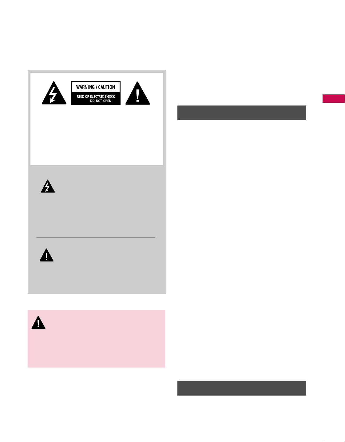
The lightning flash with arrowhead sym-
bol, within an equilateral triangle, is
intended to alert the user to the pres-
ence of uninsulated “dangerous voltage” within
the product’s enclosure that may be of sufficient
magnitude to constitute a risk of electric shock
to persons.
The exclamation point within an equi-
lateral triangle is intended to alert the
user to the presence of important
operating and maintenance (servicing) instruc-
tions in the literature accompanying the appli-
ance.
TO REDUCE THE RISK OF ELECTRIC SHOCK
DO NOT REMOVE COVER (OR BACK). NO
USER SERVICEABLE PARTS INSIDE. REFER TO
QUALIFIED SERVICE PERSONNEL.
WARNING/CAUTION
TO REDUCE THE RISK OF FIRE AND ELECTRIC
SHOCK, DO NOT EXPOSE THIS PRODUCT TO
RAIN OR MOISTURE.
SAFETY INSTRUCTION
2
IMPORTANT SAFETY INSTRUCTIONS
SAFETY INSTRUCTION
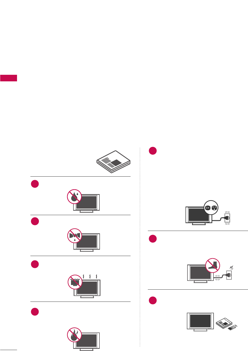
Read these instructions.
Keep these instructions.
Heed all warnings.
Follow all instructions.
Do not use this apparatus near water
Clean only with dry cloth.
Do not block any ventilation openings. Install in
accordance with the manufacturer’s instructions.
Do not install near any heat sources such as
radiators, heat registers, stoves, or other appa-
ratus (including amplifiers)that produce heat.
Do not defeat the safety purpose of the
polarized or grounding-type plug. A polarized
plug has two blades with one wider than the
other. A grounding type plug has two blades
and a third grounding prong, The wide blade
or the third prong are provided for your safe-
ty. If the provided plug does not fit into your
outlet, consult an electrician for replacement
of the obsolete outlet.
Protect the power cord from being walked on
or pinched particularly at plugs, convenience
receptacles, and the point where they exit
from the apparatus.
Only use attachments/accessories specified
by the manufacturer.
Important safety instructions shall be provided with each apparatus. This information shall be given in a separate
booklet or sheet, or be located before any operating instructions in an instruction for installation for use and
supplied with the apparatus.
This information shall be given in a language acceptable to the country where the apparatus is intended to
be used.
The important safety instructions shall be entitled “Important Safety Instructions”. The following safety
instructions shall be included where applicable, and, when used, shall be verbatim as follows. Additional safety
information may be included by adding statements after the end of the following safety instruction list. At
the manufacturer’s option, a picture or drawing that illustrates the intent of a specific safety instruction may
be placed immediately adjacent to that safety instruction :
Owner's Manual
1
2
3
4
5
6
7
SAFETY INSTRUCTION
3
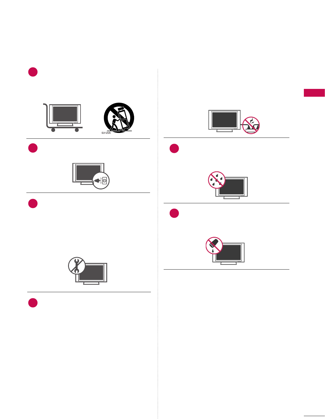
Use only with the cart, stand, tripod, bracket,
or table specified by the manufacturer, or sold
with the apparatus. When a cart is used, use
caution when moving the cart/apparatus
combination to avoid injury from tip-over.
Unplug this apparatus during lightning storms
or when unused for long periods of time.
Refer all servicing to qualified service person-
nel. Servicing is required when the apparatus
has been damaged in any way, such as power-
supply cord or plug is damaged, liquid has
been spilled or objects have fallen into the
apparatus, the apparatus has exposed to rain
or moisture, does not operate normally, or
has been dropped.
CAUTION concerning the Power Cord :
Most appliances recommend they be placed
upon a dedicated circuit; that is, a single out-
let circuit which powers only that appliance
and has no additional outlets or branch cir-
cuits. Check the specification page of this
owner's manual to be certain.
Do not overload wall outlets. Overloaded wall
outlets, loose or damaged wall outlets, exten-
sion cords, frayed power cords, or damaged
or cracked wire insulation are dangerous. Any
of these conditions could result in electric
shock or fire. Periodically examine the cord of
your appliance, and if its appearance indicates
damage or deterioration, unplug it, discontinue
use of the appliance, and have the cord
replaced with an exact replacement part by an
authorized servicer. Protect the power cord
from physical or mechanical abuse, such as
being twisted, kinked, pinched, closed in a
door, or walked upon. Pay particular attention
to plugs, wall outlets, and the point where the
cord exits the appliance.
Outdoor Use Marking :
WARNING - To Reduce The Risk Of Fire Or
Electric Shock, Do Not Expose This Appliance
To Rain Or Moisture
Wet Location Marking : Apparatus shall not
be exposed to dripping or splashing and no
objects filled with liquids, such as vases, shall
be placed on or over apparatus.
8
9
10
11
12
13
INTRODUCTION
9
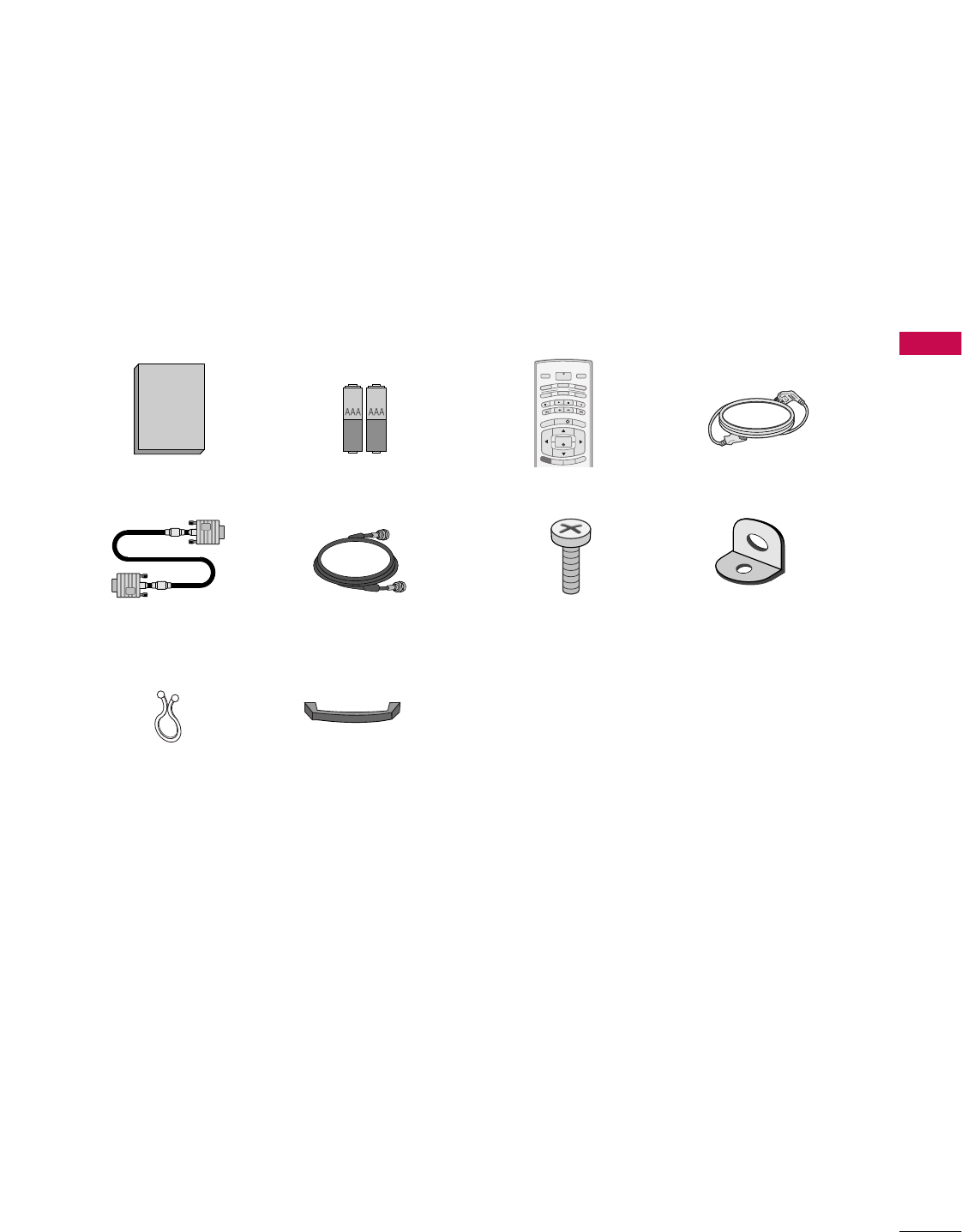
ACCESSORIES
Ensure that the following accessories are included with your plasma display. If an accessory is missing, please
contact the dealer where you purchased the product.
Owner's Manual
Owner’s Manual Batteries
MENU
INFO i
TV GUIDE
ENTER
EXIT
SAP
CC
RATIO
POWER
DAY -
DAY+
VCR
TV
DVD
AUDIO
CABLE
STB
MODE
TV INPUT
INPUT
Remote Control Power Cord
D-sub 15 pin Cable 75ohm Round Cable
Cable Management
(Refer to p.15)
Twister Holder
Arrange the wires
with the twister holder.
2-TV Brackets,
2-Wall Brackets
2-TV Bracket Bolts
INTRODUCTION
10
INTRODUCTION
CONTROLS
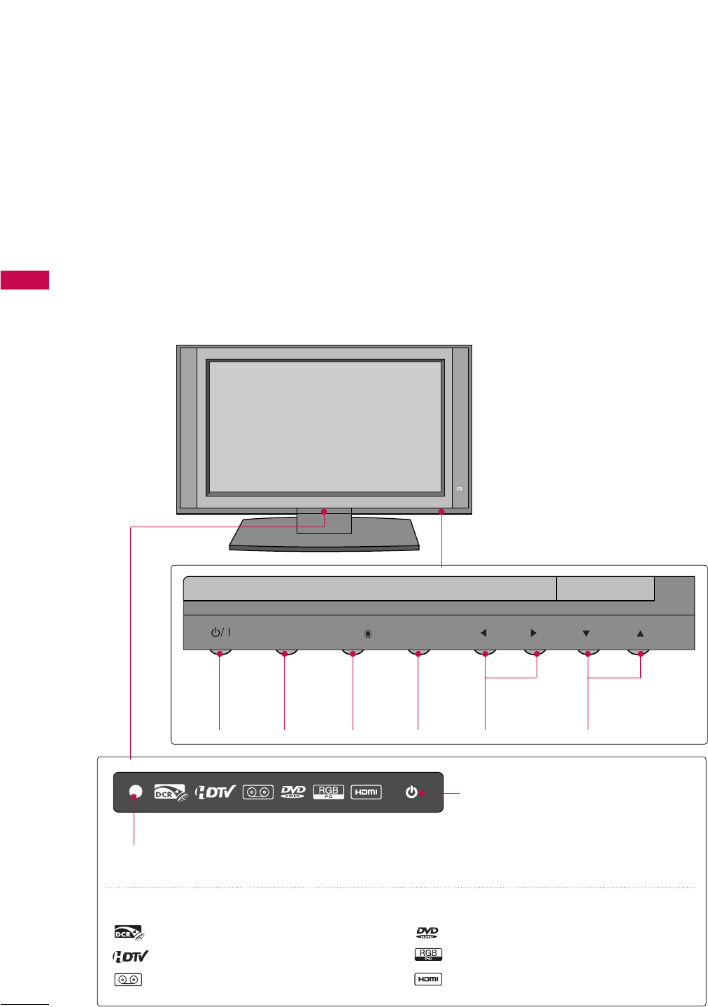
This is a representation of the front panel of models 37LB1DA TVs.
■
Here shown may be somewhat different from your TV.
Front Panel Controls
CH
VOL
MENU
INPUT
TV GUIDE
POWER
Button
TV
GUIDE
Button
INPUT
Button
MENU
Button
VOLUME
(FF,GG)Buttons
CHANNEL
(EE,DD)Buttons
CH
VOL
MENU
INPUT
TV GUIDE
Remote Control Sensor
Power Standby Indicator
Illuminates red in standby mode.
When the TV is turned on, the indicator
blinks white and then illuminates white
before the picture is displayed.
INDEX
Inserting the CableCARDs.
HDTV mode
AV mode
Component mode
RGB-PC mode
HDMI1/DVI or HDMI2 mode
INTRODUCTION
11
CONNECTION OPTION
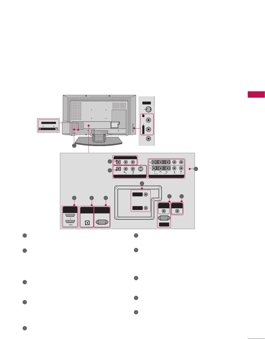
Back Connection Panel
S-VIDEOVIDEO AUDIO
AV IN 2
Cable CARD
Cable CARD
L/MONO R
HDMI IN
DIGITAL AUDIO
OUT
OPTICAL
RS-232C IN
(CONTROL & SERVICE)
AUDIO IN
(RGB/DVI)
COMPONENT IN
VIDEO
AUDIO
VIDEO
AUDIO
( )
S-VIDEO
AV IN 1
AV OUT
ANTENNA
IN
CABLE
IN
REMOTE
CONTROL
RGB IN
(PC/DTV)
HDMI INHDMI IN
DIGITAL AUDIO DIGITAL AUDIO
OUTOUT
OPTICALPTICAL
RS-232C INRS-232C IN
(CONTROL(CONTROL
&
SERVICE)SERVICE)
AUDIO INAUDIO IN
(RGB/DVI)(RGB/DVI)
COMPONENT INCOMPONENT IN
VIDEOVIDEO
AUDIOAUDIO
VIDEOVIDEO
AUDIOAUDIO
MONO
( )
S-VIDEOS-VIDEO
AV IN 1AV IN 1
AV OUTAV OUT
ANTENNAANTENNA
ININ
CABLECABLE
ININ
REMOTEREMOTE
CONTROL CONTROL
RGB INRGB IN
(PC (PC/DTV)DTV)
S-VIDEO Input
Provides better picture quality than the
video input.
AUDIO Input
Connections are available for listening to
stereo sound from an external device.
VIDEO Input
Connects the video signal from a video
device.
CableCARD™
Used for
CableCARD™
Cable Service
Provider.
This is a back panel of 37LB1DA.
AV OUT
Connect a second TV or monitor.
AV (Audio/Video) IN 1
Connect audio/video output from an external
device to these jacks.
S-VIDEO
Connect S-Video out from an S-VIDEO device.
COMPONENT IN
Connect a component video/audio device to these
jacks.
HDMI IN
Connect a HDMI signal to 1(DVI) or 2.
Or DVI(VIDEO)signal to the 1(DVI) port with a DVI
to HDMI cable.
DIGITAL AUDIO OUT
Connect digital audio from various types of equipment.
Note: In standby mode, these ports do not work.
RS-232C IN (CONTROL & SERVICE) PORT
Connect to the RS-232C port on a PC.
ANTENNA IN
Connect over-the air signals to this jack.
CABLE IN
Connect cable signals to this jack.
RGB/AUDIO IN
Connect the monitor output from a PC to the
appropriate input port.
Remote Control Port
Connect your wired remote control.
Power Cord Socket
For operation with AC power.
Caution:
Never attempt to operate the TV on DC power.
10
1
2
4
1 6
7
8
9
10
2
3
4
5
5 6
7
8
3
9
INSTALLATION
14
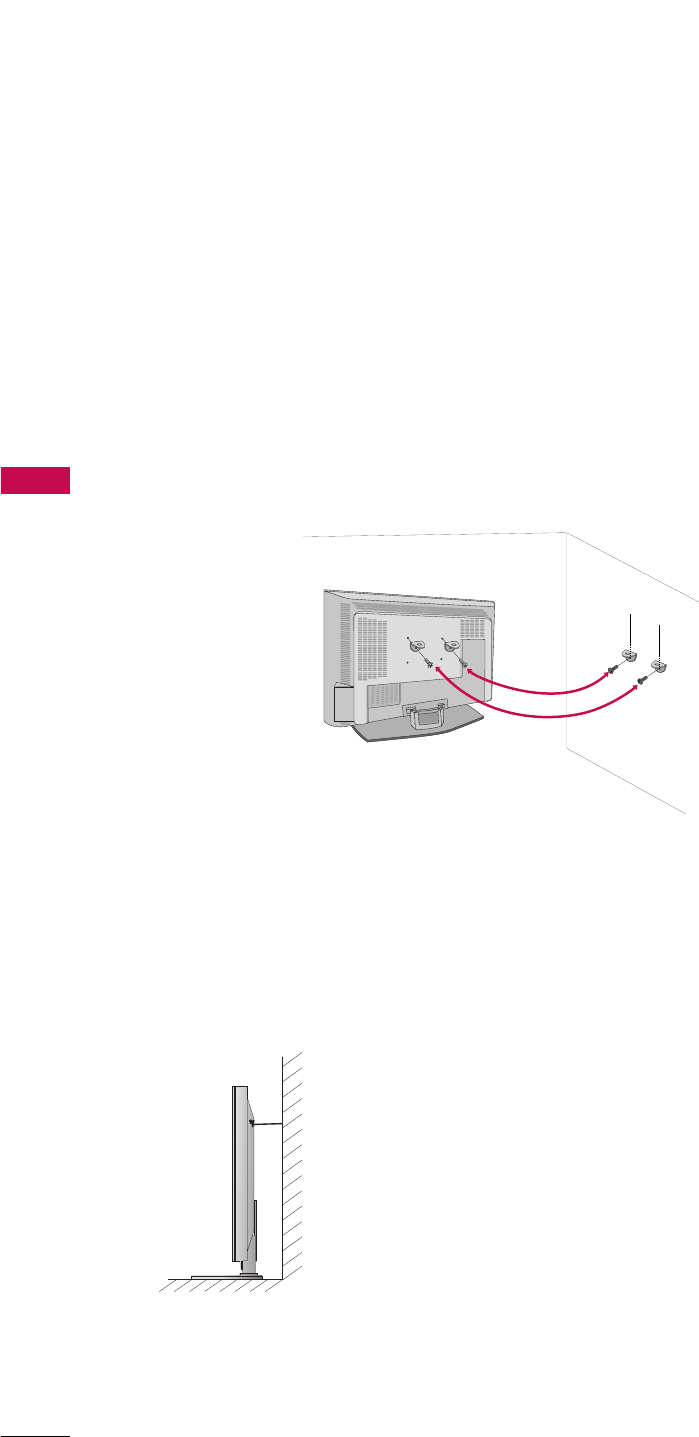
TO ATTACH THE TV TO A WALL
INSTALLATION
We recommend that you set up the TV close to a wall so it cannot fall over if pushed backwards.
Additionally, we recommend that the TV be attached to a wall so it cannot be pulled in a forward direction, poten-
tially causing injury or damaging the product.
Caution: Please make sure that children don’t climb on or hang from the TV.
■Insert the eye-bolts (or TV brackets and bolts) to tighten the product to the wall as shown in the picture.
*If your TV have bolts in the upper holes, loosen the bolts.
Insert the eye-bolts and tighten them securely in the upper holes.
Secure the wall brackets with the bolts (not provided as parts of the product, must purchase separately ) on
the wall. Match the height of the bracket that is mounted on the wall to the holes in the product.
Ensure the eye-bolts or brackets are tightened securely.
■Use a sturdy rope (not provided as parts of the product, must purchase sep-
arately) to tie the product. It is safer to tie the rope so it becomes horizon-
tal between the wall and the product.
INSTALLATION
15
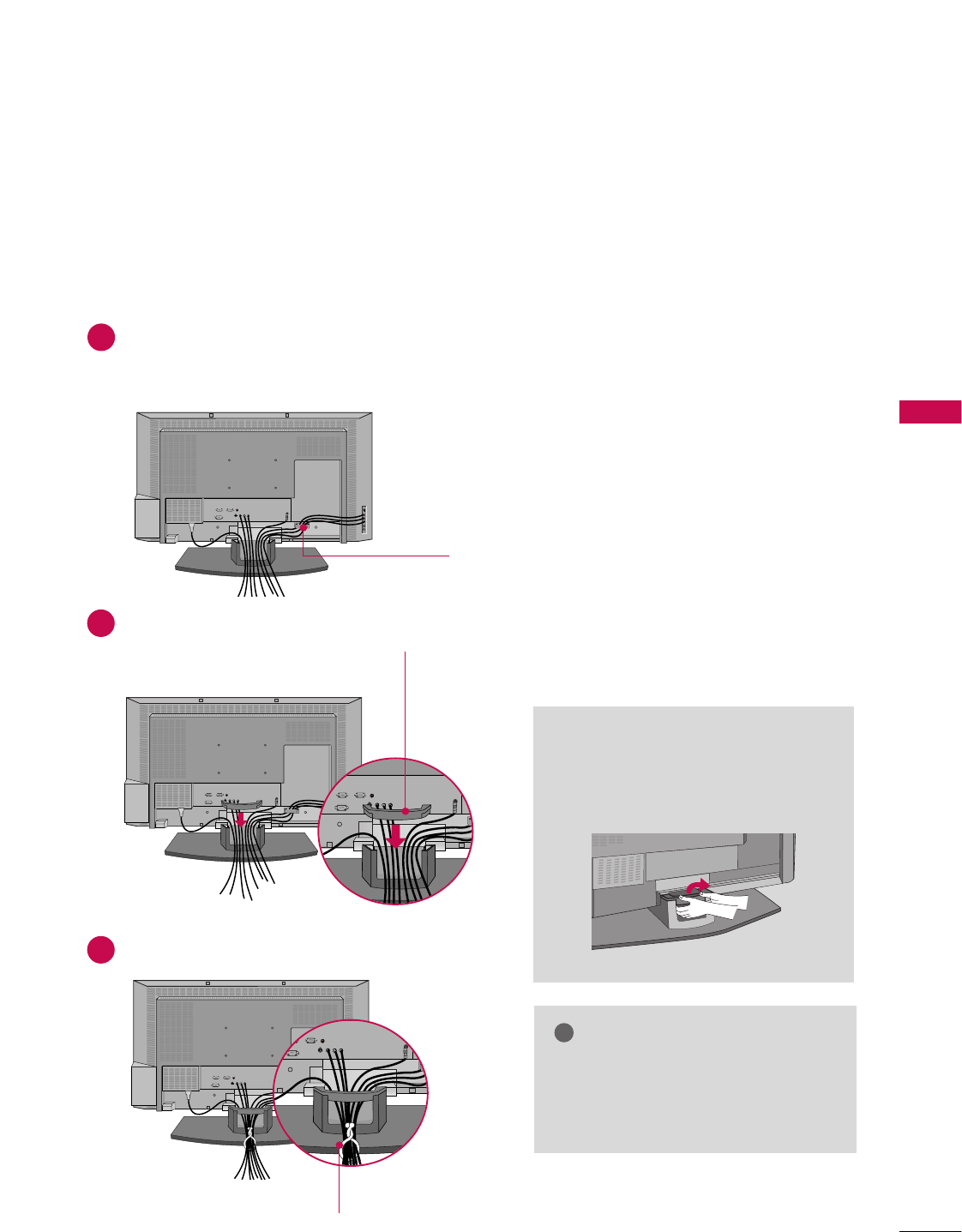
WIRE ARRANGEMENT
This function explains the features available on the 37LB1DA.
Connect the cables as necessary.
After connecting the cables neatly, arrange the cables to the Cable Holder.
To connect an additional equipment, see the External equipment Connections section.
Install the CABLE MANAGEMENT as shown.
How to remove the CABLE
MANAGEMENT
GGHold the CABLE MANAGEMENT
with both hands and pull it backward.
CABLE MANAGEMENT
GGDo not hold the CABLE MANAGEMENT
when moving the product.
- If the product is dropped, you may be
injured or the product may be broken.
NOTE
!
CABLE HOLDER
1
2
Bundle the cables using the supplied twister holder.
3
TWISTER HOLDER
INSTALLATION
16
INSTALLATION
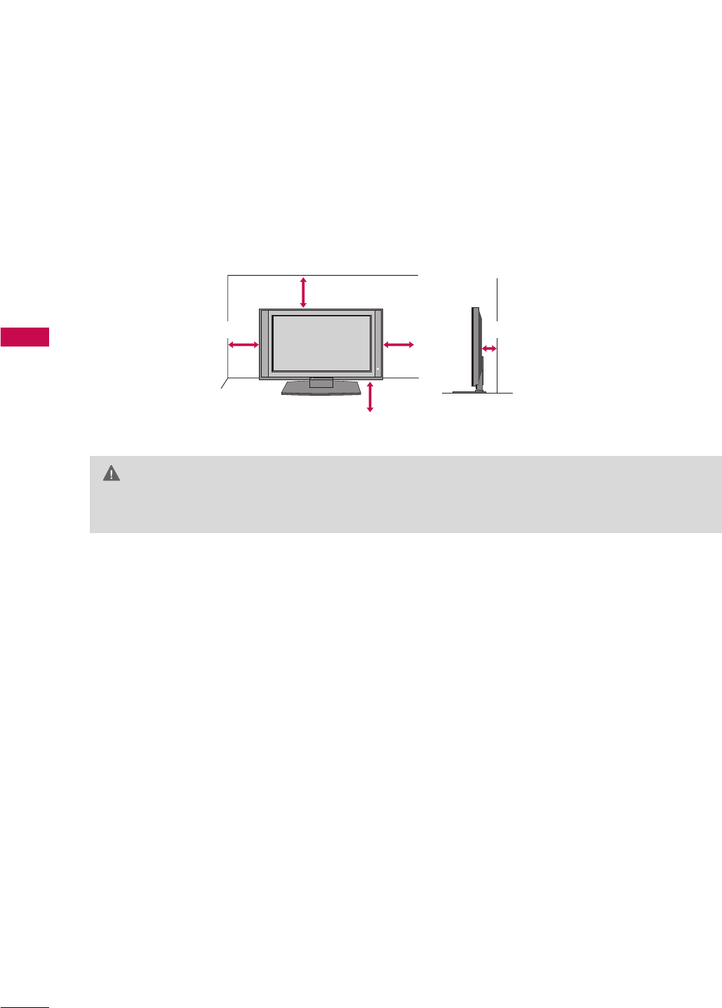
DESKTOP PEDESTAL INSTALLATION
For proper ventilation, allow a clearance of 4inches on each side from the wall.
4 inches
4 inches
4 inches
GGEnsure adequate ventilation by following the clearance recommendations.
CAUTION
4 inches 4 inches
INSTALLATION
17
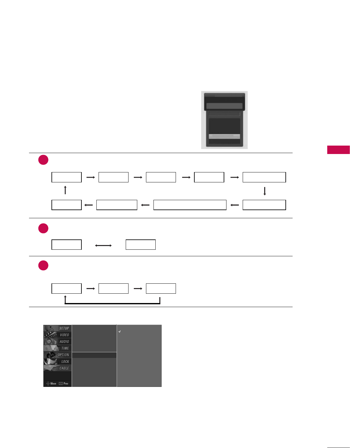
AUTO LINK
■You can also select MMaaiinn IInnppuuttin the SSeettuuppmenu.
■AAnntteennnnaa: Select it when watching the TV/DTV.
■CCaabbllee: Select it when watching the CATV/CADTV.
■AAVV 11--22: Select it when watching the VCR or external equipment.
■CCoommppoonneenntt 11--22: Select it when using the DVD or the Digital set-top box depend on connector.
■RRGGBB--PPCC//RRGGBB--DDTTVV: Select it when using PC or Digital set-top box depend on connector.
■HHDDMMII11//DDVVII,, HHDDMMII22: Select it when using DVD, PC or Digital set-top box depend on connector.
Press the IINNPPUUTT button and then displays the connected
external equipment list on the screen.
Press the EENNTTEERRbutton to change the main input to the active
external equipment. Use the DDor EE button to select the main
input source.
EZ Scan
Manual Scan
Channel Edit
DTV Signal
Main Input G
Sub Input
Input Label
Set ID
Antenna
Cable
AV 1
AV 2
Component1
Component2
RGB-PC
HDMI1/DVI
HDMI2
Antenna
Cable
AV 1
AV 2
Component1
Auto Link
AV 2
AAnntteennnnaaCCaabbllee
When every external equipment is connected:
1
When any external equipment is not connected:
2
When some External Equipment is connected:
(ex: When connected to AV 2)
3
AAnntteennnnaaCCaabbllee
AAVV11
AAnntteennnnaaCCaabblleeAAVV22
AAVV22CCoommppoonneenntt11
HHDDMMII22HHDDMMII11//DDVVIIRRGGBB--DDTTVV ((oorr RRGGBB--PPCC))CCoommppoonneenntt22
INSTALLATION
18
ANTENNA OR CABLE CONNECTION
CONNECTIONS & SETUP
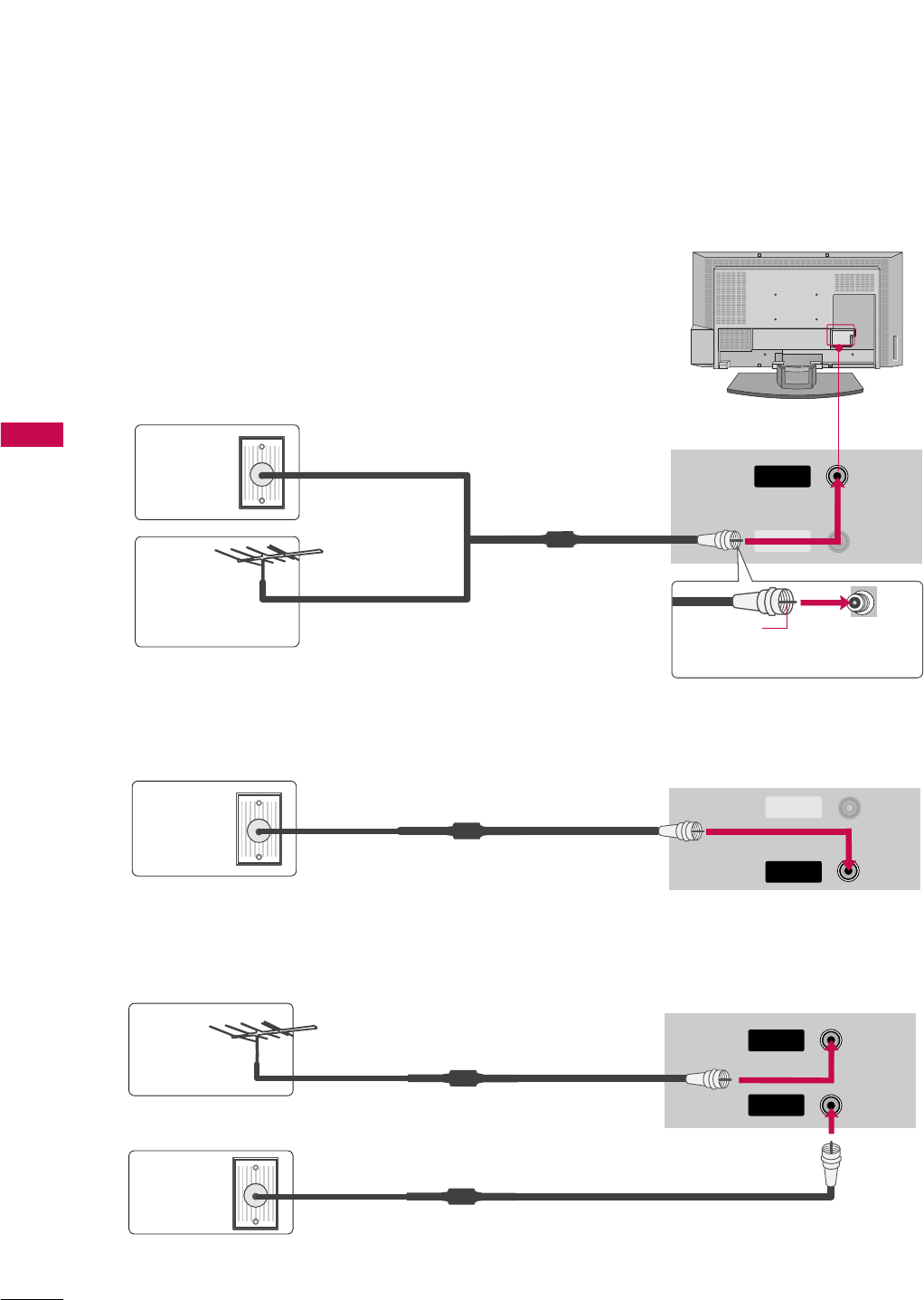
1. Antenna (analog or digital)
Wall Antenna Socket or Outdoor Antenna without a Cable Box Connections.
For optimum picture quality, adjust antenna direction if needed.
ANTENNA
IN
CABLE
IN
CABLE
IN
CABLE
IN
CABLE
IN
ANTENNA
IN
CABLE
IN
CABLE
IN
CABLE
IN
ANTENNA
IN
CABLE
IN
2. Cable box
3. Using both cable and antenna
Multi-family Dwellings/Apartments
(Connect to wall antenna socket)
Single-family Dwellings /Houses
(Connect to wall jack for outdoor antenna)
Outdoor
Antenna
(VHF, UHF)
Wall
Antenna
Socket
RF Coaxial Wire (75 ohm)
Bronze Wire
Be careful not to bend the bronze
wire when connecting the antenna.
Cable TV
Wall Jack
Cable TV
Wall Jack
Antenna
RF Coaxial Wire (75 ohm)
RF Coaxial Wire (75 ohm)
RF Coaxial Wire (75 ohm)
HDMI IN
DIGITAL AUDIO
OUT
OPTICAL
RS-232C IN
(CONTROL
&
SERVICE)
AUDIO IN
(RGB/DVI)
COMPONENT IN
VIDEO
AUDIO
VIDEO
AUDIO
( )
S-VIDEO
AV IN 1
AV OUT
ANTENNA
IN
CABLE
IN
REMOTE
CONTROL
RGB IN
(PC/DTV)
CONNECTIONS & SETUP
19
The TV will let you know when the analog, cable, and digital channel scans are complete.
NOTE
!
CABLE
IN
ANTENNA
IN
CABLE
IN
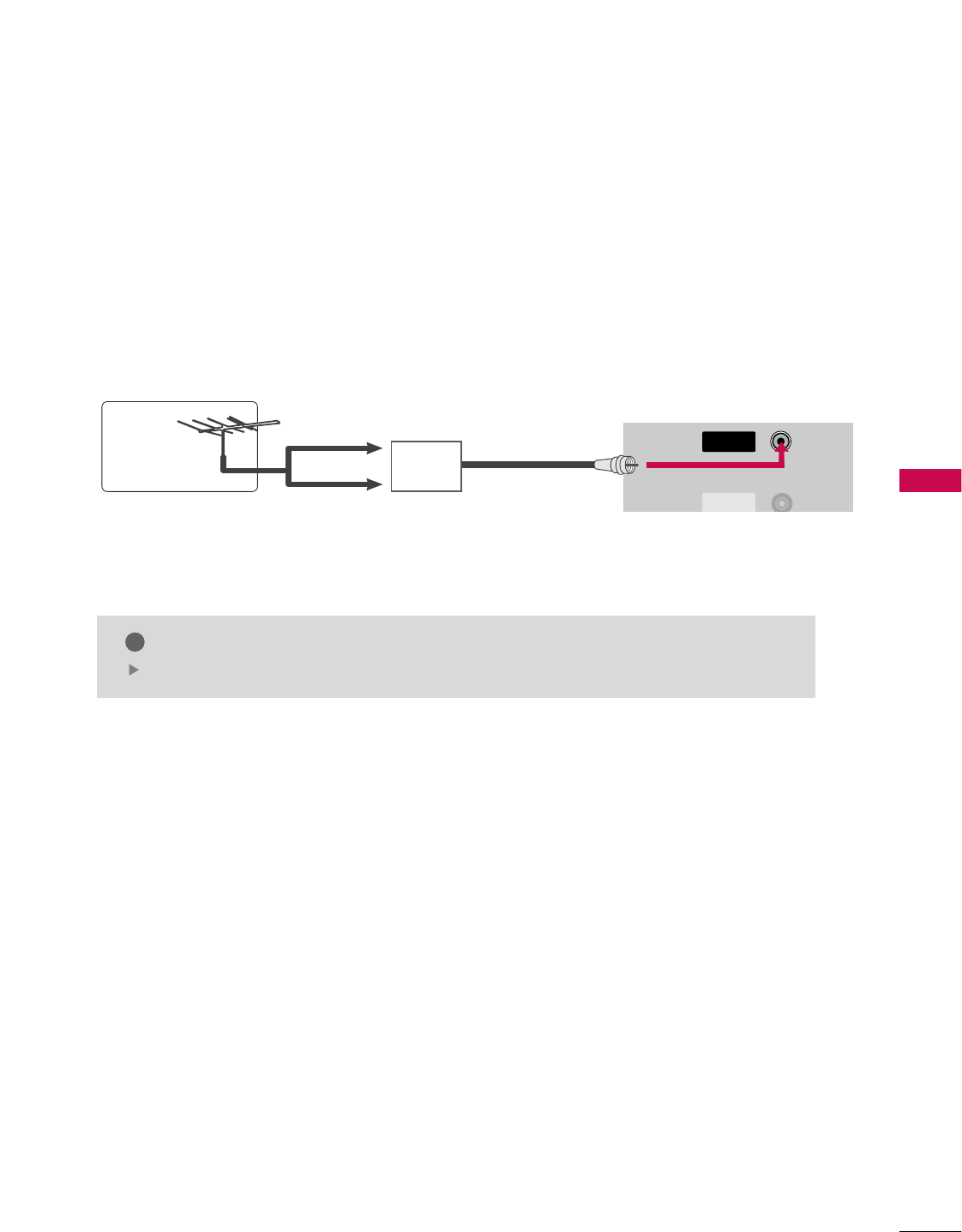
■To improve the picture quality in a poor signal area, please purchase a signal amplifier and install properly.
■If the antenna needs to be split for two TV’s, install a 2-Way Signal Splitter.
■If the antenna is not installed properly, contact your dealer for assistance.
Antenna
UHF
Signal
Amplifier
VHF
CONNECTIONS & SETUP
20
CONNECTIONS & SETUP
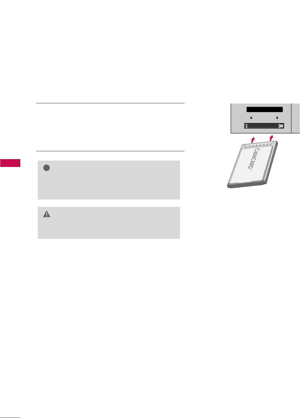
CABLECARDTM SETUP
1. How to use
Insert the CableCARDTM from your cable service provider
into the CableCARDTM slot on the back of your TV.
If pairing information about this TV and the CableCARD is
displayed on the screen, contact your cable service
provider.
GGThis TV supports CableCARDTM technology from
Motorola, Scientific Atlanta, and SCM.
NOTE
!
GGWhen removing, do not drop it as this may cause
damage to the CableCARDTM.
CAUTION
ANTENNA
IN
CABLE
IN
Cable CARD
Cable CARD
CONNECTIONS & SETUP
21
HDSTB SETUP
This TV can receive Digital Over-the-air/Cable signals without an external digital set-top box. However, if you
do receive digital signals from a digital set-top box or other digital external device, refer to the figure as
shown below.
This TV supports HDCP (High-bandwidth Digital Contents Protection)protocol for Digital Contents
(480p,720p,1080i).
Y L RP
B
P
R
S-VIDEO
ANTENNA
IN
CABLE
IN
VIDEO
AUDIOUDIO
COMPONENT IN
ANTENNA
IN
CABLE
IN
HDMI IN
2
1(DVI)
ANTENNA
IN
CABLE
IN
HDMI IN
2
1(DVI)
ANTENNA
IN
CABLE
IN
RGB IN
AUDIO (RGB/DVI)
RGB IN
AUDIO (RGB/DVI)
RGB (PC
/
DTV)
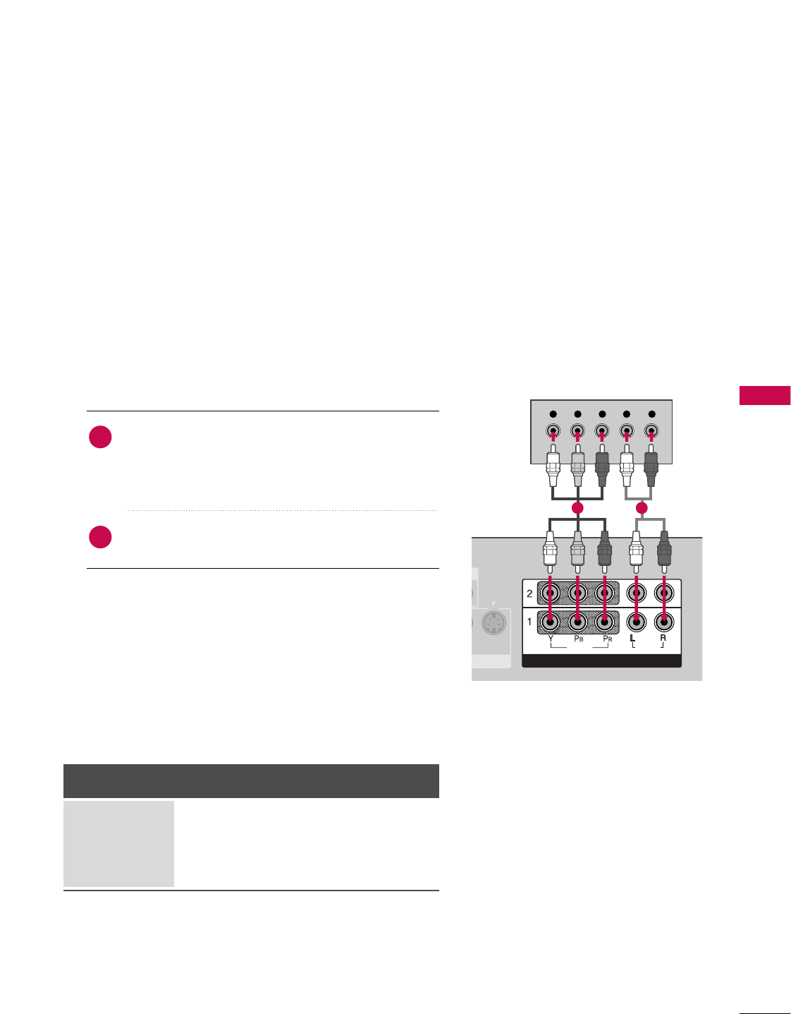
When connecting Component cable
1. How to connect
Connect the video outputs (Y, PB, PR)of the digital set
top box to the CCOOMMPPOONNEENNTT IINN VVIIDDEEOO 11jacks
onthe set. Match the jack colors
(Y = green, PB= blue, and PR= red).
Connect the audio output of the digital set-top box to
the CCOOMMPPOONNEENNTT IINN VVIIDDEEOO 11jacks on the set.
2
1
2. How to use
■Turn on the digital set-top box.
(Refer to the owner’s manual for the digital set-top box.)
■Select CCOOMMPPOONNEENNTT 11input source with using the
IINNPPUUTTbutton on the remote control.
■If connected to CCOOMMPPOONNEENNTT 22input, select CCOOMMPPOO--
NNEENNTT 22input source.
Signal
480i
480p
720p
1080 i
Component 1/2
Yes
Yes
Yes
Yes
RGB-DTV, HDMI
/DVI, HDMI2
No
Yes
Yes
Yes
1 2
CONNECTIONS & SETUP
22
CONNECTIONS & SETUP
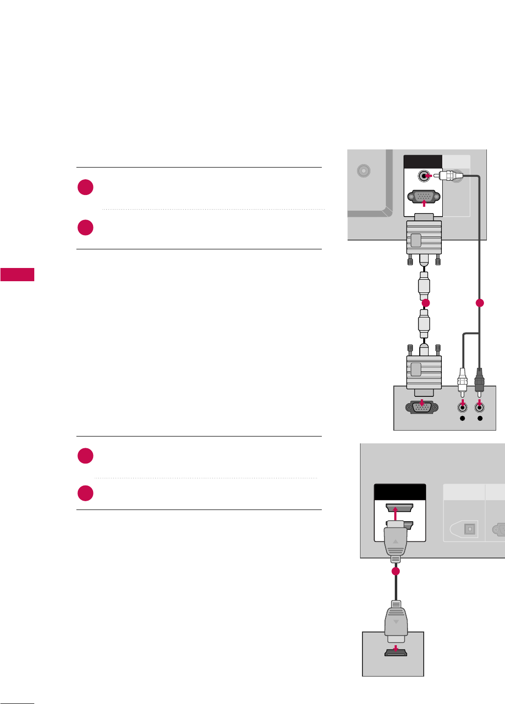
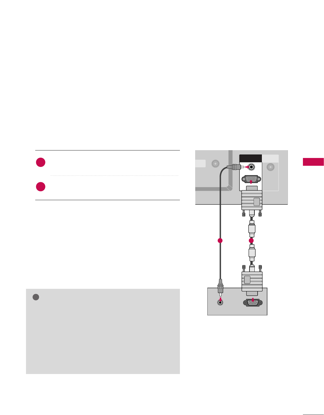
When connecting D-sub 15pin cable
Connect the RGB output of the digital set-top box to
the RRGGBB ((PPCC//DDTTVV))jack on the set.
Connect the audio outputs of the set-top box to the
AAUUDDIIOO ((RRGGBB//DDVVII))jack on the set.
1. How to connect
2. How to use
■Turn on the digital set-top box.
(Refer to the owner’s manual for the digital set-top box.)
■Select RRGGBB--DDTTVVinput source with using the IINNPPUUTT
button on the remote control.
When connecting HDMI cable
Connect the digital set-top box to HHDDMMII IINN 11((DDVVII))
or 22 jack on the set.
No separated audio connection is necessary.
1. How to connect
2. How to use
■Turn on the digital set-top box.
(Refer to the owner’s manual for the digital set-top box.)
■Select HHDDMMII11//DDVVIIor HHDDMMII22input source with using
the IINNPPUUTTbutton on the remote control.
■If the digital set-top box supports Auto HDMI function, the
output resolution of the source device will be automatically
set to 1280x720p.
■If the digital set-top box player does not support Auto
HDMI, you need to set the output resolution appropriate
ly.
To get the best picture quality, adjust the output resolution
of the source device to 1280x720p.
2
1
2
1
ANTENNA
IN
CABLE
IN
VIDEO
AUDIO
COMPONENT IN
ANTENNA
IN
CABLE
IN
HDMI IN
2
1(DVI)
ANTENNA
IN
CABLE
IN
HDMI IN
2
1(DVI)
ANTENNA
IN
CABLE
IN
L R
RGB INPUT
RGB IN
AUDIO (RGB/DVI)
REMOTE
CONTROL IN
RGB IN
AUDIO (RGB/DVI)
RGB (PC
/
DTV)
1 2
ANTENNA
IN
CABLE
IN
VIDEO
AUDIO
COMPONENT IN
DIGITAL AUDIO
OUT
OPTICAL
RS-2
(CONTRO
ANTENNA
IN
CABLE
IN
HDMI INHDMI IN
2
1(DVI)
HDMI-DTV OUTPUT
ANTENNA
IN
CABLE
IN
HDMI IN
2
1(DVI)
ANTENNA
IN
CABLE
IN
RGB IN
AUDIO (RGB/DVI)
RGB IN
AUDIO (RGB/DVI)
RGB (PC
/
DTV)
1
CONNECTIONS & SETUP
23
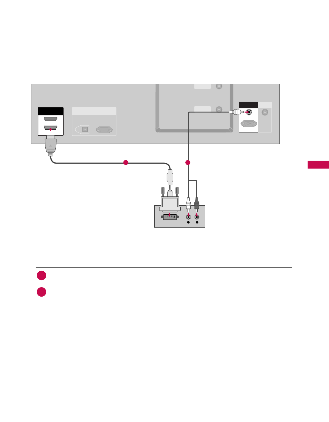
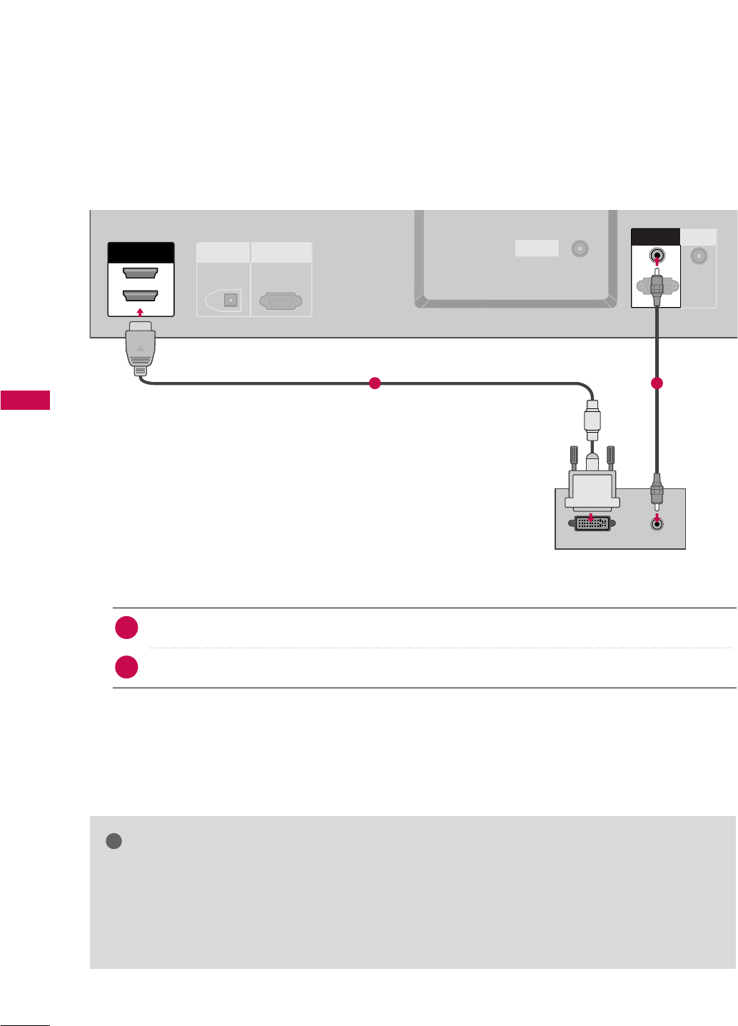
When connecting HDMI to DVI cable
ANTENNA
IN
CABLE
IN
VIDEO
AUDIO
COMPONENT IN
ANTENNA
IN
CABLE
IN
HDMI IN
2
1(DVI)
L R
DIGITAL AUDIO
OUT
OPTICAL
RS-232C IN
(CONTROL
&
SERVICE)
ANTENNA
IN
CABLE
IN
HDMI IN
2
1(DVI)
DVI-DTV OUTPUT
ANTENNA
IN
CABLE
IN
REMOTE
CONTROL IN
RGB IN
AUDIO (RGB/DVI)AUDIO (RGB/DVI)
RGB (PC
/
DTV)
RGB IN
AUDIO (RGB/DVI)
RGB (PC
/
DTV)
Connect the DVI output of the digital set-top box to the HHDDMMIIIINN 11((DDVVII)) jack on the set.
Connect the audio output of the digital set-top box to the AAUUDDIIOO((RRGGBB//DDVVII))jack on the set.
1. How to connect
■Turn on the digital set-top box. (Refer to the owner’s manual for the digital set-top box.)
■Select HHDDMMII11//DDVVIIinput source with using the IINNPPUUTTbutton on the remote control.
2. How to use
2
1
1 2
CONNECTIONS & SETUP
31
PC SETUP
This TV provides Plug and Play capability, meaning that the PC adjusts automatically to the TV's settings.
The TV perceives 640x480, 60Hz as DTV 480p based on the PC graphic card. If necessary, change the
screen scanning rate for the graphic card accordingly.
When connecting D-sub 15pin cable
GGCheck the image on your TV. There may be noise associ-
ated with the resolution, vertical pattern, contrast or
brightness in PC mode. If noise is present, change the PC
output to another resolution, change the refresh rate to
another rate or adjust the brightness and contrast on the
VIDEO menu until the picture is clear. If the refresh rate
of the PC graphic card can not be changed, change the
PC graphic card or consult the manufacturer of the PC
graphic card.
NOTE
!
ANTENNA
IN
BLECABLE
NIN
REMOTE
CONTROL IN
RGB OUTPUTAUDIO
ANTENNA
IN
CABLE
IN
HDMI IN
2
1(DVI)
RGB (PC
/
DTV)
AUDIO (RGB/DVI)
RGB IN
RGB IN
AUDIO (RGB/DVI)
Connect the RGB output of the PC to the RRGGBB
((PPCC//DDTTVV)) jack on the set.
Connect the PC audio output to the AAUUDDIIOO
((RRGGBB//DDVVII))jack on the set.
1. How to connect
2. How to use
■Turn on the PC and the set.
■Select RRGGBB--PPCCinput source in main input option of
SETUP menu. (GG pp..6677)
■Once you select RRGGBB--PPCCin main input option of SSEETTUUPP
menu, IINNPPUUTTbutton is also available for this purpose.
2
1
12
CONNECTIONS & SETUP
32
CONNECTIONS & SETUP
When connecting HDMI to DVI cable
GGHDMI2 source does not support DVI source.
GGIf the PC has a DVI output and no HDMI output, a separated audio connection is necessary.
GGIf the PC does not support Auto DVI, you need to set the output resolution appropriately. To get the
best picture quality, adjust the output resolution of PC graphics card's output resolution to 1024x768,
60Hz.
NOTE
!
ANTENNA
IN
CABLE
IN
DIGITAL AUDIO
OUT
OPTICAL
RS-232C IN
(CONTROL
&
SERVICE)
ANTENNA
IN
CABLECABLE
IN
HDMI INHDMI IN
2
1(DVI)VI)
REMOTE
CONTROL IN
DVI-PC OUTPUT AUDIO
RGB (PC
/
DTV)
AUDIO (RGB/DVI)
RGB IN
RGB INRGB IN
AUDIO (RGB/DVI)AUDIO (RGB/DVI)
RGB (PC
/
DTV)
Connect the DVI output of the PC to the HHDDMMII IINN 11((DDVVII)) jack on the set.
Connect the PC audio output to the AAUUDDIIOO((RRGGBB//DDVVII))jack on the set.
1. How to connect
■Turn on the PC and the set
■Select HHDDMMII11//DDVVIIinput source with using the IINNPPUUTTbutton on the remote control.
2. How to use
2
1
1 2

CONNECTIONS & SETUP
33
GGTo get the the best picture quality, adjust the PC
graphics card to 1024x768, 60Hz.
GGDepending on the graphics card, DOS mode may
not work if a HDMI to DVI Cable is in use.
GGWhen Source Devices are connected with
HDMI/DVI Input, the output PC Resolution(VGA,
SVGA, XGA), Position and Size may not fit on the
Screen. As shown in the picture, press the
ADJUST button to adjust the screen Position of
the TV SET and contact a PC graphics card ser-
vice center.
GGWhen Source Devices connected with HDMI/DVI
Input, output TV SET Resolution (480p, 720p,
1080i) and TV SET Display fit EIA/CEA-861-B
Specification to Screen. If not, refer to the Manual
of HDMI/DVI Source Devices or contact your ser-
vice center.
GGIf the HDMI/DVI Source Device is not connected
to the Cable or if there is a poor cable connec-
tion, "No signal" is displayed in the HDMI/DVI
Input. In this case, that Video Resolution is not
supported. If "Invalid Format" is displayed, refer to
the Source Device manual or contact your service
center.
GGAvoid keeping a fixed image on the screen for a
long period of time. The fixed image may become
permanently imprinted on the screen.
GGThe synchronization input form for Horizontal
and Vertical frequencies is separate.
NOTES
!
Surpported Display Specifications (RGB/HDMI-PC)
Horizontal Vertical
Frequency(KHz)Frequency(Hz)
31.468 70.09
31.469 70.08
31.469 59.94
37.861 72.80
37.500 75.00
35.156 56.25
37.879 60.31
48.077 72.18
46.875 75.00
48.363 60.00
56.476 70.06
60.023 75.02
47.776 59.870
47.720 59.799
Resolution
720x400
1360x768
640x350
* RGB-PC mode only: 640x350, 720X400
* HDMI-PC mode only: 1280x768
640x480
800x600
1024x768
Surpported Display Specifications (RGB/HDMI-DTV)
Horizontal Vertical
Frequency(KHz)Frequency(Hz)
31.47 60
31.47 59.94
45.00 60.00
44.96 59.94
33.75 60.00
33.72 59.94
Resolution
720x480
1280x720
1920x1080
1280x768
BASIC OPERATION
34
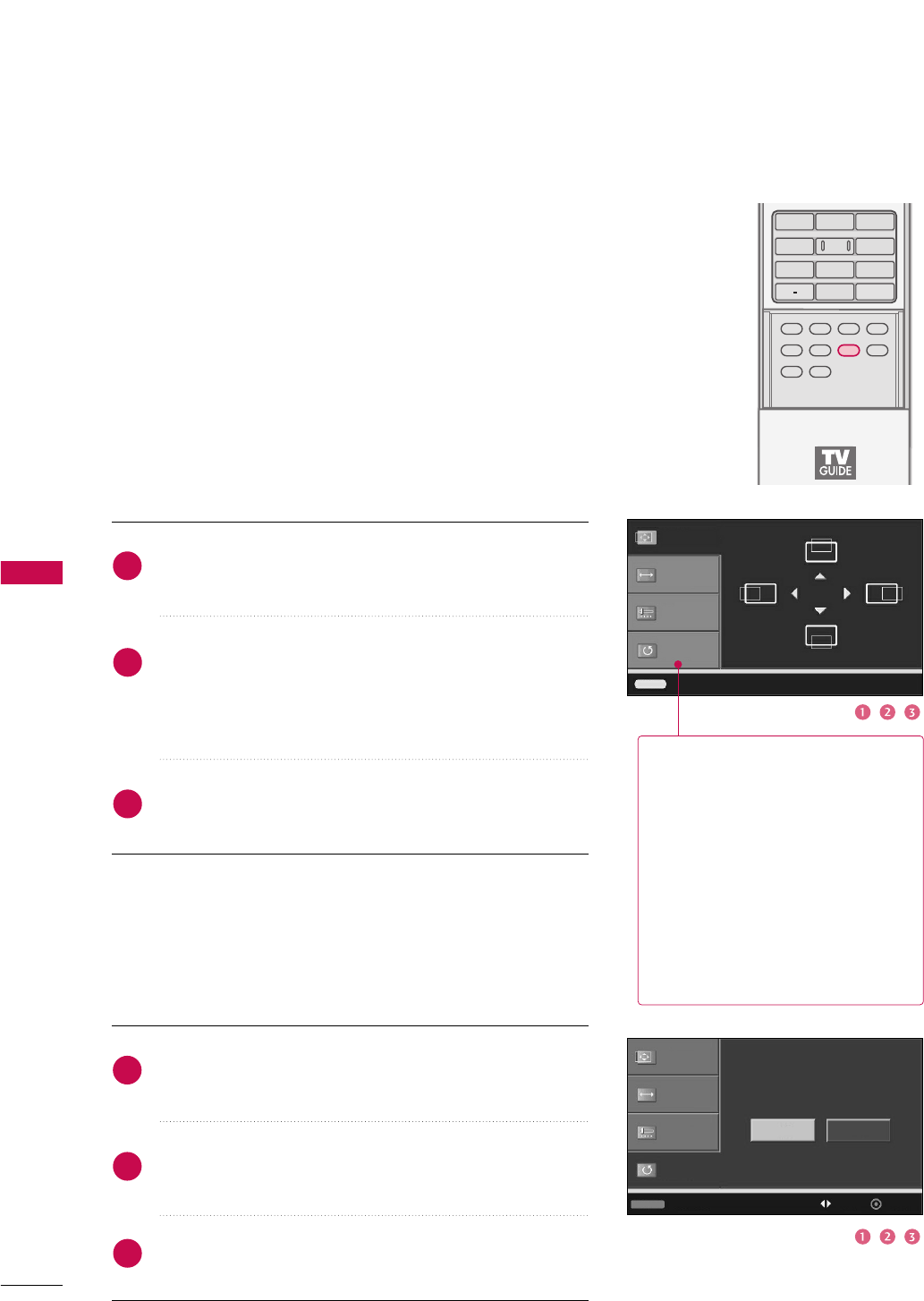
Screen Setup for PC mode
Overview
When RGB connect to PC output and select the RGB-PC in Main
Input, this function is used.
When HDMI/DVI connect to PC output and select HDMI/DVI input,
this function is used.
In RGB-DTV mode, SIZE and PHASE is not available.
Adjustment for screen Position, Size, Phase, Reset
Press the AADDJJUUSSTTbutton and then use DDor EEbutton to
select PPoossiittiioonn, SSiizzee, or PPhhaassee.
Press the EENNTTEERRbutton and then use DDEE FFGG button to
make appropriate adjustments.
■The PPhhaasseeadjustment range is --1166 ~++1166.
■The SSiizzeeadjustment range is --3300 ~++3300.
Press the EENNTTEERRbutton.
Position GG
Size
Phase
Reset
Adjust Close
Initializing (Reset to original factory values)
Press the AADDJJUUSSTTbutton and then use DDor EEbutton to
select RReesseett.
Press the EENNTTEERR button and then use FFor GGbutton to
select YYeess.
Press the EENNTTEERRbutton.
Position
Size
Phase
Reset GG
To initialize the adjusted values
APM
TIMER
ADJUSTADJUST
SWAP
PIP CH +PIP CH -
PIP
PIP INPUT
1 2 3
4 5 6
78
0
9
FLASHBK
EZ SOUND
EZ PIC
Initialize Settings
Yes No
Adjust Previous Move Select
1
2
3
1
2
3
PPoossiittiioonnThis function is to adjust picture
to left/right and up/down as you
prefer.
SSiizzeeThis function is to minimize any
vertical bars or stripes visible on
the screen background. And the
horizontal screen size will also
change.
PPhhaasseeThis function allows you to
remove any horizontal noise and
clear or sharpen the image of char-
acters. In HDMI/DVI-PC mode,
PHASE is not available.
APPENDIX
108
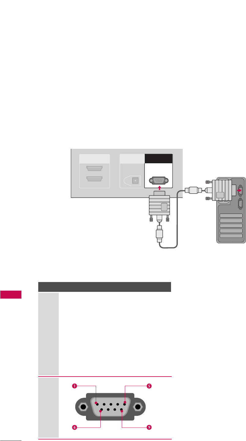
EXTERNAL CONTROL DEVICE SETUP
APPENDIX
RS-232C Setup
Connect the RS-232C (serial port) input jack to an external control device (such as a computer or an A/V
control system) to control the product’s functions externally.
Connect the serial port of the control device to the RS-232C jack on the product back panel.
Note: RS-232C connection cables are not supplied with the product.
HDMI/DVI IN
2
1(DVI)
DIGITAL AUDIO
OUT
OPTICAL
RS-232C INRS-232C IN
(CONTROL(CONTROL
&
SERVICE)SERVICE)
Type of Connector; D-Sub 9-Pin Male
No. Pin Name
1 No connection
2 RXD (Receive data)
3 TXD (Transmit data)
4 DTR (DTE side ready)
5 GND
6 DSR (DCE side ready)
7RTS
(Ready to send)
8 CTS (Clear to send)
9 No Connection

APPENDIX
117
Programming a code into a remote mode
To find out whether your remote control can operate each device without programming, turn on the device
(such as a VCR) and press the corresponding mode button on the remote.
After that, press the PPOOWWEERRbutton. If the device is turned off and it responds properly the remote control
need not be programmed. If not, the remote should be programmed to operate the device. The program-
ming procedures are explained below.
Press the MMEENNUUand MMUUTTEEbutton continuously at the same time for two seconds; the currently selected
device button is illuminated.
If you don't press any button for 20 seconds, the light on the mode button will be turned off. In that case,
you have to repeat from step 2.
Enter the appropriate code from the code table on the following pages. When pressing the button, the light
blinks at a time. If the device turned off, the programming is successful.
Press the MMEENNUUbutton to store the code. After blinking twice, this code is stored.
Test the remote control functions to see if the device responds properly. If not, steps 2-5.
The provided universal remote control can be programmed to operate most remote-controllable devices.
Note that the remote may not control all models of other brands.
2
3
4
5
1
PROGRAMMING THE REMOTE CONTROL
APPENDIX
125
PRODUCT SPECIFICATIONS
■The specifications shown above may be changed without prior notice for quality improvement.
37LB1DA
(37LB1DA-UB)
MODELS
41.2 x 27.3 x 10.3 inches
1045.8 x 693.8 x 260.4 mm
41.2 x 23.4 x 5.2 inches
1045.8 x 594.4 x 133.0 mm
69.7 pounds / 31.6 kg
55.8 pounds / 25.3 kg
AC100-240V ~ 50/60Hz
NTSC-M, ATSC, 64 & 256 QAM
VHF 2-13, UHF 14-69, CATV 1-135, DTV 2-69, CADTV 1-135
75 ohm
32 ~ 104°F (0 ~40°C)
Less than 80%
-4 ~ 140°F (-20 ~60°C)
0 ~ 85%
Dimensions
(Width x Height x Depth)
Weight
Power requirement
Television System
Program Coverage
External Antenna Impedance
Environment condition
including stand
excluding stand
including stand
excluding stand
Operating Temperature
Operating Humidity
Storage Temperature
Storage Humidity