LG Electronics USA 37LDBT LCD TV/Monitor User Manual MFL34797004 Edit1
LG Electronics USA LCD TV/Monitor MFL34797004 Edit1
Contents
- 1. Users Manual 1
- 2. Users Manual 2
- 3. Users Manual 3
Users Manual 1

P/NO : MFL34797004 (0612-REV00)
As an ENERGY STAR
Partner LGE U. S. A.,Inc.
has determined that this
product meets the ENERGY
STAR guidelines for
energy efficiency.
As an ENERGY STAR
Partner LGE U. S. A.,Inc.
has determined that this
product meets the ENERGY
STAR guidelines for
energy efficiency.
LCD TV PLASMA TV
32LC7D
37LC 7 D
42LC7D
42PC5D
50PC5D
LCD TV MODELS PLASMA TV MODELS
WARNING / CAUTION
1
WARNING / CAUTION
To prevent fire or shock hazards, do not expose
this product to rain or moisture.
FCC NOTICE
Class B digital device
This equipment has been tested and found to com-
ply with the limits for a Class B digital device, pur-
suant to Part 15 of the FCC Rules. These limits are
designed to provide reasonable protection against
harmful interference in a residential installation. This
equipment generates, uses and can radiate radio fre-
quency energy and, if not installed and used in
accordance with the instructions, may cause harmful
interference to radio communications. However,
there is no guarantee that interference will not
occur in a particular installation. If this equipment
does cause harmful interference to radio or televi-
sion reception, which can be determined by turning
the equipment off and on, the user is encouraged to
try to correct the interference by one or more of
the following measures:
- Reorient or relocate the receiving antenna.
- Increase the separation between the equipment
and receiver.
- Connect the equipment to an outlet on a circuit
different from that to which the receiver is con-
nected.
- Consult the dealer or an experienced radio/TV
technician for help.
Any changes or modifications not expressly
approved by the party responsible for compliance
could void the user’s authority to operate the
equipment.
CAUTION
Do not attempt to modify this product in any way
without written authorization from LG Electronics.
Unauthorized modification could void the user’s
authority to operate this product
The lightning flash with arrowhead
symbol, within an equilateral triangle,
is intended to alert the user to the
presence of uninsulated “dangerous voltage”
within the product’s enclosure that may be of
sufficient magnitude to constitute a risk of electric
shock to persons.
The exclamation point within an equilateral
triangle is intended to alert the user to
the presence of important operating and main-
tenance (servicing) instructions in the literature
accompanying the appliance.
TO REDUCE THE RISK OF ELECTRIC SHOCK
DO NOT REMOVE COVER (OR BACK). NO
USER SERVICEABLE PARTS INSIDE. REFER TO
QUALIFIED SERVICE PERSONNEL.
WARNING/CAUTION
TO REDUCE THE RISK OF FIRE AND ELECTRIC
SHOCK, DO NOT EXPOSE THIS PRODUCT TO
RAIN OR MOISTURE.
WARNING / CAUTION
2
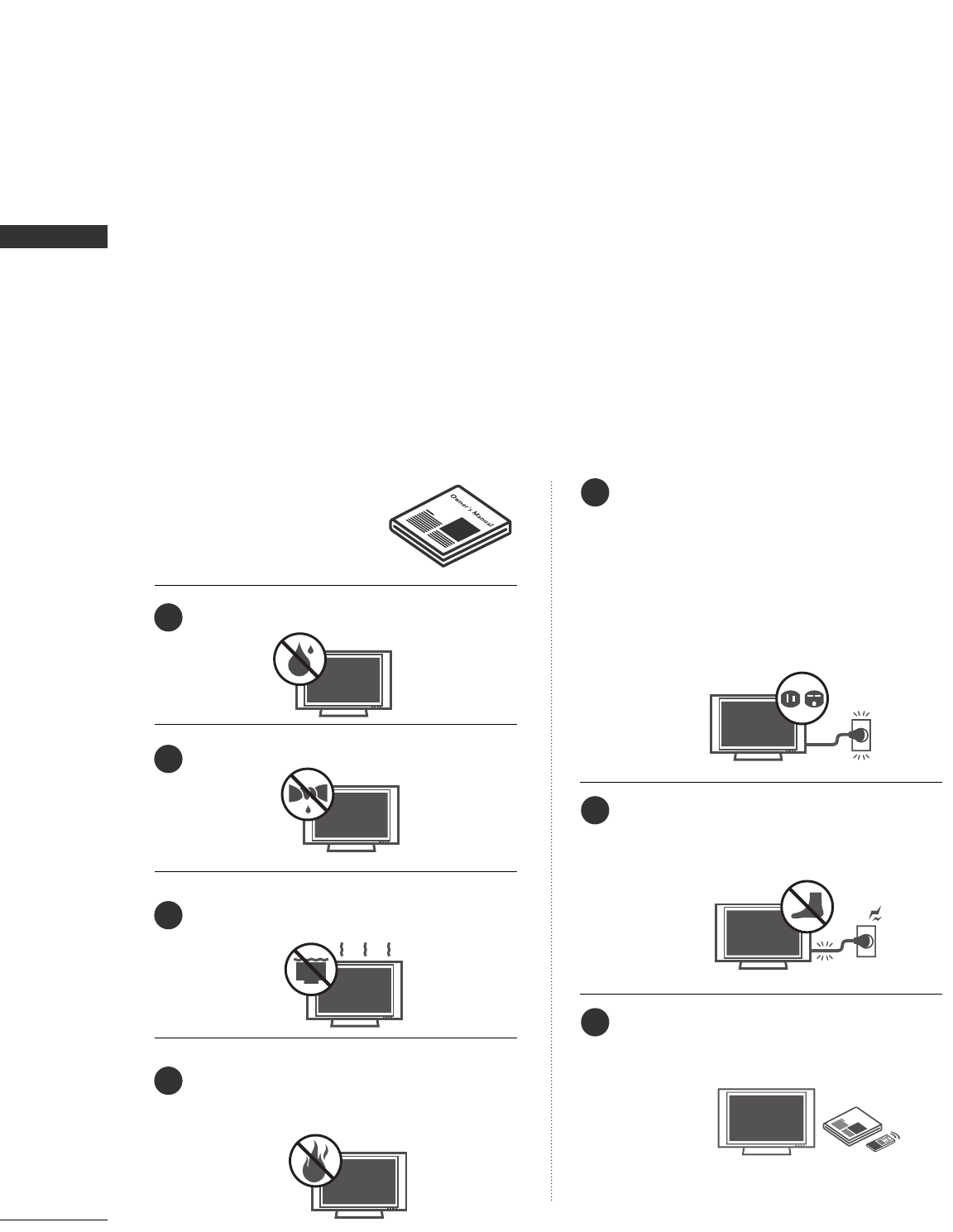
IMPORTANT SAFETY INSTRUCTIONS
SAFETY INSTRUCTION
Read these instructions.
Keep these instructions.
Heed all warnings.
Follow all instructions.
Do not use this apparatus near water
Clean only with dry cloth.
Do not block any ventilation openings. Install in
accordance with the manufacturer’s instructions.
Do not install near any heat sources such as
radiators, heat registers, stoves, or other apparatus
(including amplifiers)that produce heat.
Do not defeat the safety purpose of the polar-
ized or grounding-type plug. A polarized plug
has two blades with one wider than the other.
A grounding type plug has two blades and a
third grounding prong, The wide blade or the
third prong are provided for your safety. If the
provided plug does not fit into your outlet,
consult an electrician for replacement of the
obsolete outlet.
Protect the power cord from being walked on
or pinched particularly at plugs, convenience
receptacles, and the point where they exit from
the apparatus.
Only use attachments/accessories specified by
the manufacturer.
Important safety instructions shall be provided with each apparatus. This information shall be given in a separate
booklet or sheet, or be located before any operating instructions in an instruction for installation for use and
supplied with the apparatus.
This information shall be given in a language acceptable to the country where the apparatus is intended to
be used.
The important safety instructions shall be entitled “Important Safety Instructions”. The following safety
instructions shall be included where applicable, and, when used, shall be verbatim as follows. Additional safety
information may be included by adding statements after the end of the following safety instruction list. At
the manufacturer’s option, a picture or drawing that illustrates the intent of a specific safety instruction may
be placed immediately adjacent to that safety instruction :
Owner Manual
Owner Manual
Owner Manual
Owner Manual
Owner Manual
Owner Manual
Owner Manual
Owner Manual
Owner Manual
Owner Manual
Owner Manual
Owner Manual
Owner ManualOwner Manual
Owner Manual
1
2
3
4
5
6
7
WARNING / CAUTION
3
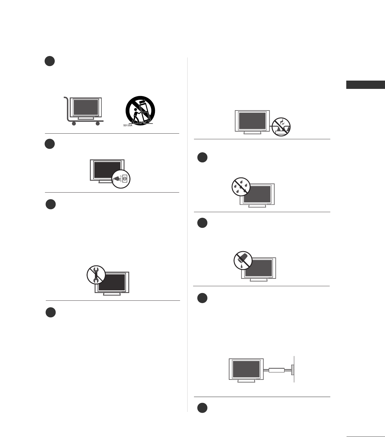
Use only with the cart, stand, tripod, bracket,
or table specified by the manufacturer, or sold
with the apparatus. When a cart is used, use
caution when moving the cart/apparatus
combination to avoid injury from tip-over.
Unplug this apparatus during lightning storms
or when unused for long periods of time.
Refer all servicing to qualified service person-
nel. Servicing is required when the apparatus
has been damaged in any way, such as power-
supply cord or plug is damaged, liquid has
been spilled or objects have fallen into the
apparatus, the apparatus has exposed to rain
or moisture, does not operate normally, or has
been dropped.
CAUTION concerning the Power Cord :
Most appliances recommend they be placed
upon a dedicated circuit; that is, a single outlet
circuit which powers only that appliance and
has no additional outlets or branch circuits.
Check the specification page of this owner's
manual to be certain.
Do not overload wall outlets. Overloaded wall
outlets, loose or damaged wall outlets, extension
cords, frayed power cords, or damaged or
cracked wire insulation are dangerous. Any of
these conditions could result in electric shock
or fire. Periodically examine the cord of your
appliance, and if its appearance indicates dam-
age or deterioration, unplug it, discontinue use
of the appliance, and have the cord replaced
with an exact replacement part by an autho-
rized servicer. Protect the power cord from
physical or mechanical abuse, such as being
twisted, kinked, pinched, closed in a door, or
walked upon. Pay particular attention to plugs,
wall outlets, and the point where the cord exits
the appliance.
Outdoor Use Marking :
WARNING - To Reduce The Risk Of Fire Or
Electric Shock, Do Not Expose This Appliance
To Rain Or Moisture
Wet Location Marking : Apparatus shall not be
exposed to dripping or splashing and no
objects filled with liquids, such as vases, shall
be placed on or over apparatus.
GGRROOUUNNDDIINNGG
Ensure that you connect the earth ground wire
to prevent possible electric shock. If ground-
ing methods are not possible, have a qualified
electrician install a separate circuit breaker.
Do not try to ground the unit by connecting it
to telephone wires, lightening rods, or gas pipes.
DDIISSCCOONNNNEECCTTIINNGG DDEEVVIICCEE FFRROOMM MMAAIINNSS
Mains plug is the disconnecting device. The
plug must remain readily operable.
Owner Manual
Owner Manual
Owner Manual
Owner Manual
Owner Manual
Owner Manual
Owner Manual
Owner Manual
Owner Manual
Owner Manual
Owner Manual
Owner Manual
Owner Manual
Owner Manual
8
9
10
11
12
13
14
15
Power
Supply
Short-circuit
Breaker

CONTENTS
4
CONTENTS
WARNING / CAUTION
. . . . . . . . . . . . . . . . . . . . . . . . . . . . 1
SAFETY INSTRUCTIONS
. . . . . . . . . . . . . . . . . . . . . . 2-3
PREPARATION
Accessories . . . . . . . . . . . . . . . . . . . . . . . . . . . . . . . . . . . . . . . . . . . . . . . . . . . . . . 5
Front & Back Panel Information . . . . . . . . . . . . . . . . . . . . . . . . . 6
Front & Back Panel Information . . . . . . . . . . . . . . . . . . . . . . . . . 8
Attaching the TV to a Wall . . . . . . . . . . . . . . . . . . . . . . . . . . . . . . . 10
Stand Installation . . . . . . . . . . . . . . . . . . . . . . . . . . . . . . . . . . . . . . . . . . . . . 11
Desktop Pedestal Installation . . . . . . . . . . . . . . . . . . . . . . . . . . . . 11
Back Cover for Wire Arrangement . . . . . . . . . . . . . . . . . . . . . 12
Antenna or Cable Connection . . . . . . . . . . . . . . . . . . . . . . . . . . 14
EXTERNAL EQUIPMENT SETUP
HD Receiver Setup . . . . . . . . . . . . . . . . . . . . . . . . . . . . . . . . . . . . . . . . . 15
DVD Setup . . . . . . . . . . . . . . . . . . . . . . . . . . . . . . . . . . . . . . . . . . . . . . . . . . . . . . 18
VCR Setup . . . . . . . . . . . . . . . . . . . . . . . . . . . . . . . . . . . . . . . . . . . . . . . . . . . . . 20
Other A/V Source Setup . . . . . . . . . . . . . . . . . . . . . . . . . . . . . . . . . 22
PC Setup . . . . . . . . . . . . . . . . . . . . . . . . . . . . . . . . . . . . . . . . . . . . . . . . . . . 23-26
AV Out Setup & Digital Audio Output . . . . . . . . . . . . . 27
WATCHING TV / CHANNEL CONTROL
Remote Control Key Functions . . . . . . . . . . . . . . . . . . . 28-29
Turning the TV On . . . . . . . . . . . . . . . . . . . . . . . . . . . . . . . . . . . . . . . . . . 30
Channel Selection . . . . . . . . . . . . . . . . . . . . . . . . . . . . . . . . . . . . . . . . . . . 30
Volume Adjustment . . . . . . . . . . . . . . . . . . . . . . . . . . . . . . . . . . . . . . . . . 30
On-Screen Menus Selection . . . . . . . . . . . . . . . . . . . . . . . . . . . . . 31
Channel Search . . . . . . . . . . . . . . . . . . . . . . . . . . . . . . . . . . . . . . . . . . . . . . . 32
- Auto Scan (EZ Scan) . . . . . . . . . . . . . . . . . . . . . . . . . . . . . . . . . 32
- Add / Delete Channel (Manual Scan) . . . . . . . . . 33
- Channel Editing . . . . . . . . . . . . . . . . . . . . . . . . . . . . . . . . . . . . . . . . 34
DTV Signal Strength . . . . . . . . . . . . . . . . . . . . . . . . . . . . . . . . . . . . . . . . 35
Input Source Selection . . . . . . . . . . . . . . . . . . . . . . . . . . . . . . . . . . . . 36
Input Label . . . . . . . . . . . . . . . . . . . . . . . . . . . . . . . . . . . . . . . . . . . . . . . . . . . . . 37
SimpLink . . . . . . . . . . . . . . . . . . . . . . . . . . . . . . . . . . . . . . . . . . . . . . . . . . . . . . . . . 38
PICTURE CONTROL
Picture Size (Aspect Ratio) Control . . . . . . . . . . . . . . . . . . 40
Preset Picture Settings . . . . . . . . . . . . . . . . . . . . . . . . . . . . . . . . . . . . . 41
- EZ Picture Preset . . . . . . . . . . . . . . . . . . . . . . . . . . . . . . . . . . . . . . 41
- Color Tone Preset. . . . . . . . . . . . . . . . . . . . . . . . . . . . . . . . . . . . . 41
Manual Picture Adjustment . . . . . . . . . . . . . . . . . . . . . . . . . . . . . . 42
- EZ Picture - User Mode . . . . . . . . . . . . . . . . . . . . . . . . . . . . 42
- Color Tone - User Mode . . . . . . . . . . . . . . . . . . . . . . . . . . . 43
XD - Picture Improvement Technology . . . . . . . . . . . . . 44
Advanced - Cinema 3:2 PulldownMode . . . . . . . . . . . . 45
Advanced - Black (Darkness) Level . . . . . . . . . . . . . . . . . . . 45
Picture Reset . . . . . . . . . . . . . . . . . . . . . . . . . . . . . . . . . . . . . . . . . . . . . . . . . 46
Low - Power Picture Mode . . . . . . . . . . . . . . . . . . . . . . . . . . . . . . . 46
Image Sticking Minimization (ISM) Method . . . . . . . 47
SOUND & LANGUAGE CONTROL
Preset Sound Setting . . . . . . . . . . . . . . . . . . . . . . . . . . . . . . . . . . . . . . . 48
Balance . . . . . . . . . . . . . . . . . . . . . . . . . . . . . . . . . . . . . . . . . . . . . . . . . . . . . . . . . . 48
Sound Setting Adjustment - User Mode . . . . . . . . . . . 49
Stereo/SAP Broadcasts Setup . . . . . . . . . . . . . . . . . . . . . . . . . . 50
TV Speakers On/Off Setup . . . . . . . . . . . . . . . . . . . . . . . . . . . . . . 50
Audio Language . . . . . . . . . . . . . . . . . . . . . . . . . . . . . . . . . . . . . . . . . . . . . . 51
On-Screen Menus Language Selection . . . . . . . . . . . . . . 51
Caption/Text . . . . . . . . . . . . . . . . . . . . . . . . . . . . . . . . . . . . . . . . . . . . . . . . . . 52
Caption Option . . . . . . . . . . . . . . . . . . . . . . . . . . . . . . . . . . . . . . . . . . . . . 54
TIME SETTING
Clock Setting . . . . . . . . . . . . . . . . . . . . . . . . . . . . . . . . . . . . . . . . . . . . . . . . . . 55
- Auto Color Setup . . . . . . . . . . . . . . . . . . . . . . . . . . . . . . . . . . . . 55
- Manual Color Setup . . . . . . . . . . . . . . . . . . . . . . . . . . . . . . . . . 56
Auto On/Off Timer Setting . . . . . . . . . . . . . . . . . . . . . . . . . . . . . 57
Sleep Timer Setting . . . . . . . . . . . . . . . . . . . . . . . . . . . . . . . . . . . . . . . . . 58
Auto Shut-off Setting . . . . . . . . . . . . . . . . . . . . . . . . . . . . . . . . . . . . . . . 58
PARENTAL CONTROL / RATINGS
Set Password & Lock System . . . . . . . . . . . . . . . . . . . . . . . . . . . 59
Channel Blocking & External Input Blocking . . . . . . 61
External Input Blocking . . . . . . . . . . . . . . . . . . . . . . . . . . . . . . . . . . 106
Movie & TV Rating . . . . . . . . . . . . . . . . . . . . . . . . . . . . . . . . . . . . . . . . . . 62
APPENDIX
Troubleshooting . . . . . . . . . . . . . . . . . . . . . . . . . . . . . . . . . . . . . . . . . . . . . . 65
Maintenance . . . . . . . . . . . . . . . . . . . . . . . . . . . . . . . . . . . . . . . . . . . . . . . . . . . 67
Product Specifications . . . . . . . . . . . . . . . . . . . . . . . . . . . . . . . . . . . . . 68
Programming the Remote Control . . . . . . . . . . . . . . . . . . . 70
IR Codes . . . . . . . . . . . . . . . . . . . . . . . . . . . . . . . . . . . . . . . . . . . . . . . . . . . . . . .74
External Control Through RS-232C . . . . . . . . . . . . . . . . .110
WARNING / CAUTION
5
PREPARATION
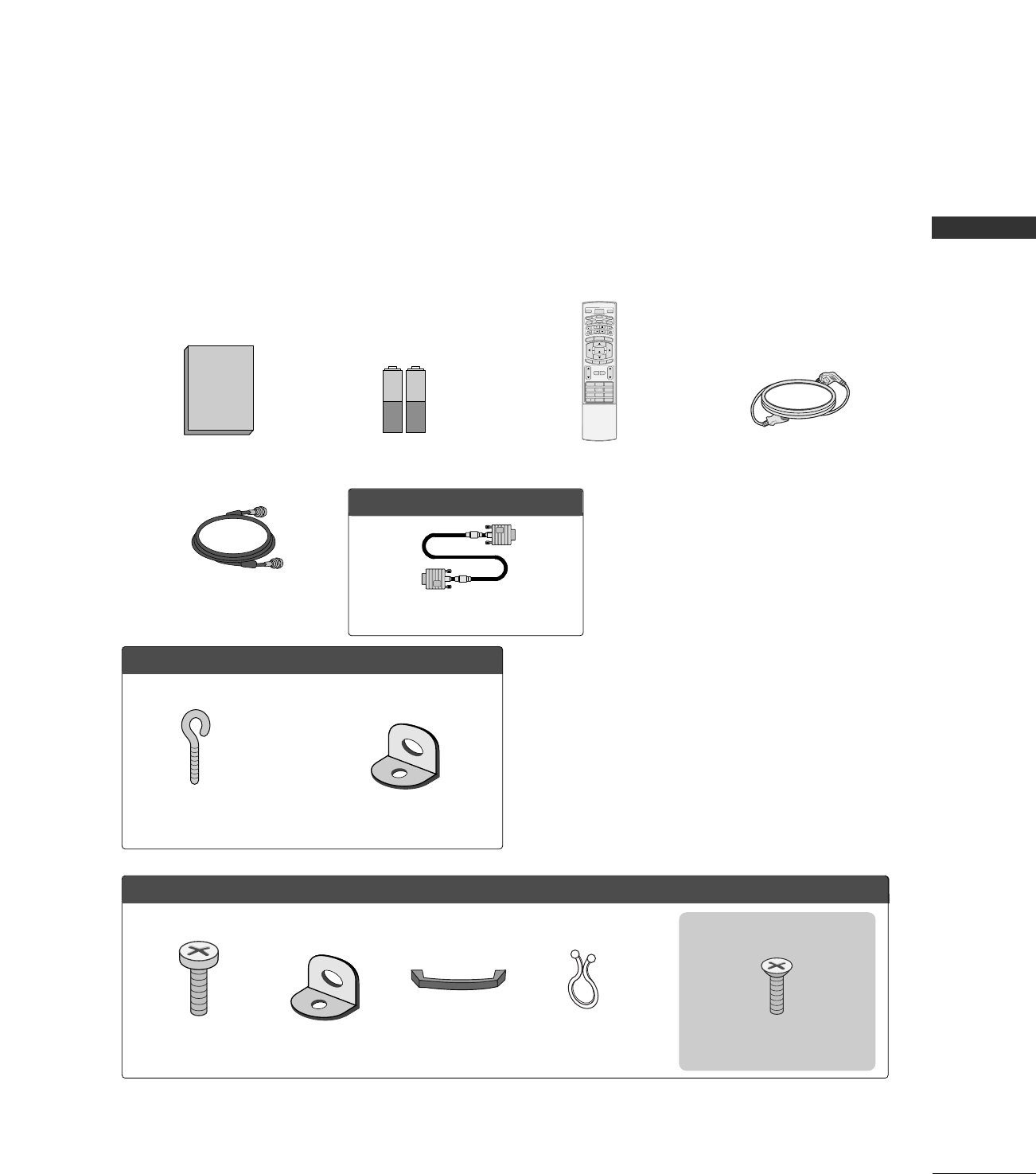
ACCESSORIES
Ensure that the following accessories are included with your product. If an accessory is missing, please con-
tact the dealer where you purchased the product.
User must use shielded signal interface cables (D-sub 15 pin cable) with ferrite cores to maintain standard
compliance for the product.
Manuel de l’Utilisateur
1.5V 1.5V
Owner’s Manual Batteries
1 2 3
4 5 6
78
0
9
BACK
VOL CH
MUTE
FAV
BRIGHT -
MENU
BRIGHT +
ENTER
EXIT
TIMER
RATIO
SIMPLINK
POWER
VCR
TV
DVD
AUDIO
CABLE
STB
MODE
TV INPUT
INPUT
Remote Control Power Cord
75ohm Round Cable
OOppttiioonn EExxttrraass
D-sub 15 pin Cable
FFoorr LLCCDD TTVV mmooddeellss
2-eye-bolts 2-Wall brackets
FFoorr PPllaassmmaa TTVV mmooddeellss
Cable Management
2- TV Bracket Bolts 2- TV Brackets,
2- Wall Brackets
Twister Holder
Arrange the wires with
the twister holder.
4-Bolts for stand assembly
(Refer to p.15)
2266””,, 3322”” oonnllyy
PREPARATION
6
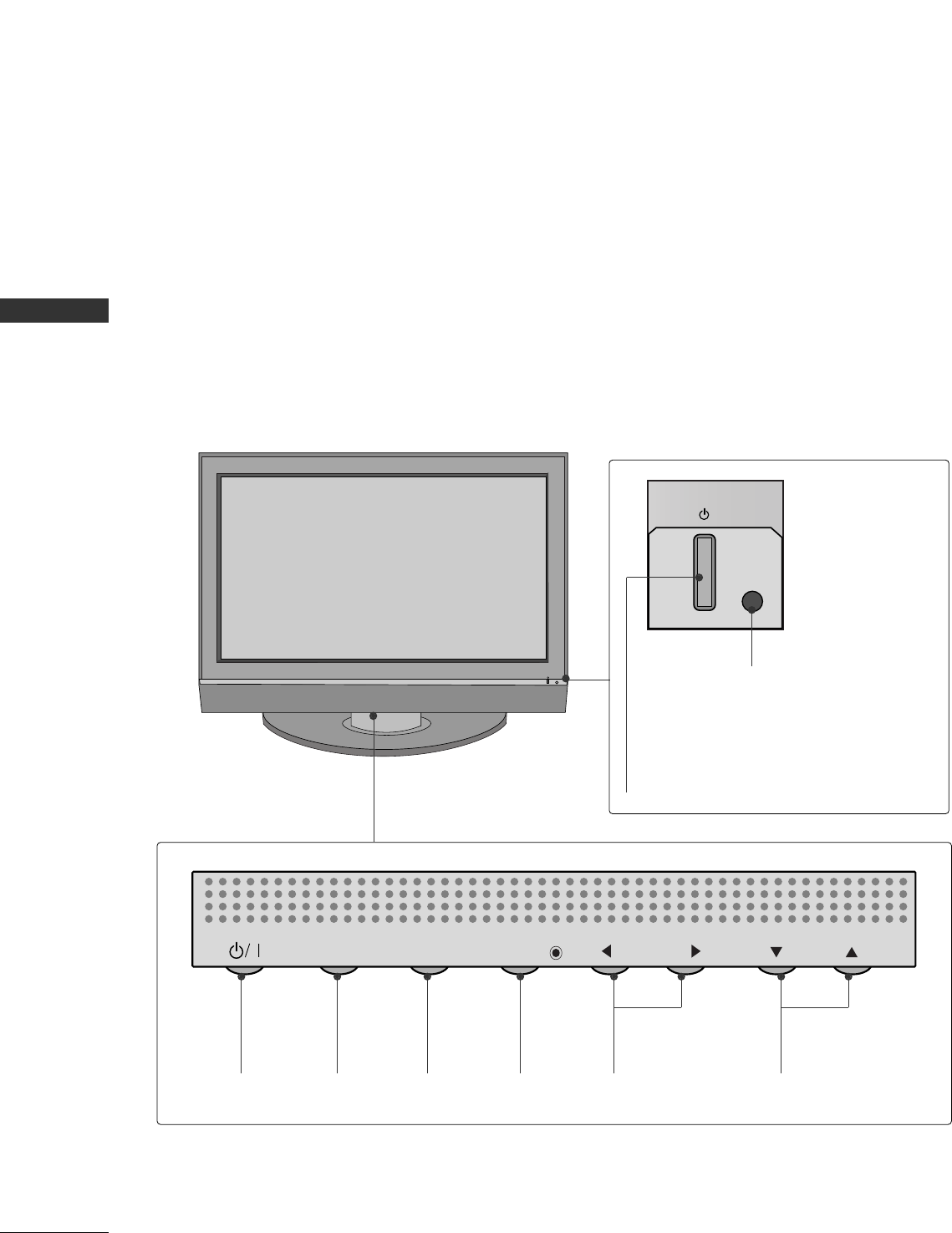
FRONT PANEL INFORMATION
PREPARTION
■
Here shown may be somewhat different from your TV.
Front Panel Controls
CH
VOL
MENU
INPUT ENTER
CH
VOL
MENU
INPUT ENTER
Power Standby Indicator
Illuminates red in standby mode.
When the TV is turned on, the indicator
blinks green and then illuminates green
before the picture is displayed.
Remote Control Sensor
POWER
Button
INPUT
Button
MENU
Button
ENTER
Button
VOLUME
(FF,GG)Buttons
CHANNEL
(EE,DD)Buttons
Plasma TV Model
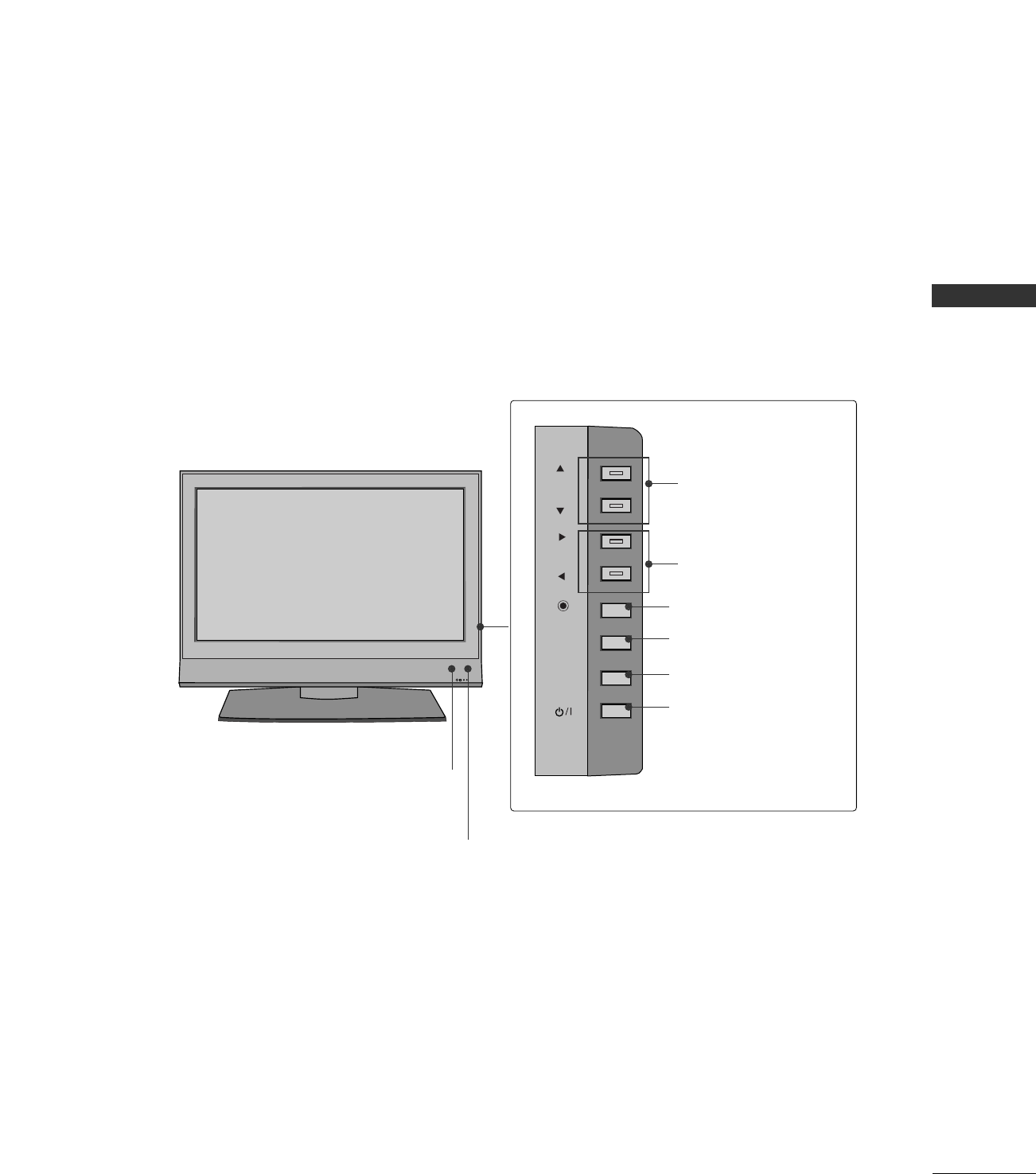
PREPARATION
7
R
CH
VOL
ENTER
MENU
INPUT
Remote Control Sensor
Power Standby Indicator
Illuminates red in standby mode.
When the TV is turned on, the indicator blinks green and
then illuminates green before the picture is displayed.
CHANNEL Buttons
VOLUME Buttons
ENTER Button
MENU Button
INPUT Button
ON/OFF Button
LCD TV Model
PREPARATION
8
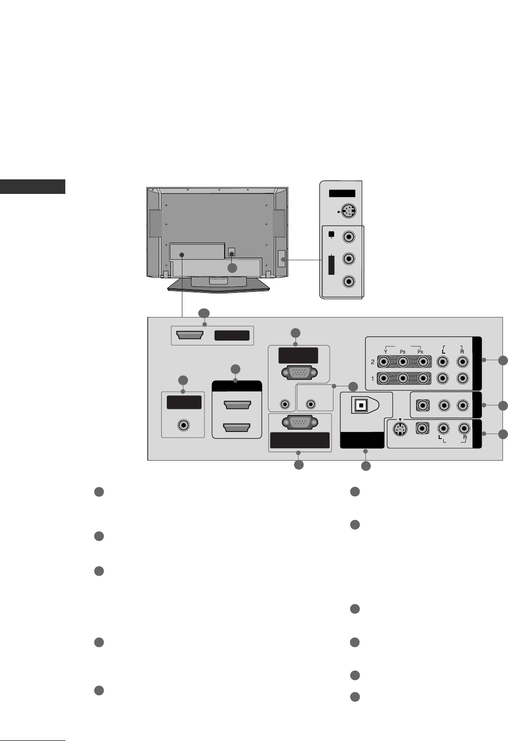
BACK PANEL INFORMATION
PREPARTION
Back Connection Panel
COMPONENT IN
Connect a component video/audio device to these
jacks.
AV OUT
Connect a second TV or monitor.
AV (Audio/Video) IN 1
Connect audio/video output from an external
device to these jacks.
S-VIDEO
Connect S-Video out from an S-VIDEO device.
ANTENNA/CABLE IN
Connect over-the air signals to this jack.
Connect cable signals to this jack.
DIGITAL AUDIO OUT
Connect digital audio from various types of equipment.
Note: In standby mode, these ports do not work.
HDMI/DVI IN
Connect a HDMI signal to 1 or 2.
RGB IN (PC)
Connect the monitor output from a PC to the
appropriate input port.
AUDIO IN (RGB/DVI)
Connect the monitor output from a PC to the
appropriate input port.
Remote Control Port
Connect your wired remote control.
RS-232C IN (CONTROL & SERVICE) PORT
Connect to the RS-232C port on a PC.
SERVICE
Power Cord Socket
For operation with AC power.
Caution: Never attempt to operate the TV on DC
power.
1
7
6
8
9
10
11
2
3
4
5
AV IN 2
L/MONO
R
AUDIO
VIDEO
S-VIDEO
( )
S-VIDEO Input
Provides better picture quality than the
video input.
AUDIO Input
Connections are available for listening to
stereo sound from an external device.
VIDEO Input
Connects the video signal from a video
device.
R
HDMI/DVI IN
VIDEO
AUDIO
VIDEO
AUDIO
MONO
( )
S-VIDEO
ANTENNA/
CABLE IN
REMOTE
CONTROL IN
RS-232C IN
(CONTROL & SERVICE)
RGB IN
(PC)
AUDIO IN
(RGB/DVI)
DIGITAL AUDIO
OUT
OPTICAL
1
2
SERVICE
COMPONENT IN AV OUT
AV IN 1
2
1
8
3
7
6
95
10
Plasma TV Model
4
11
PREPARATION
9
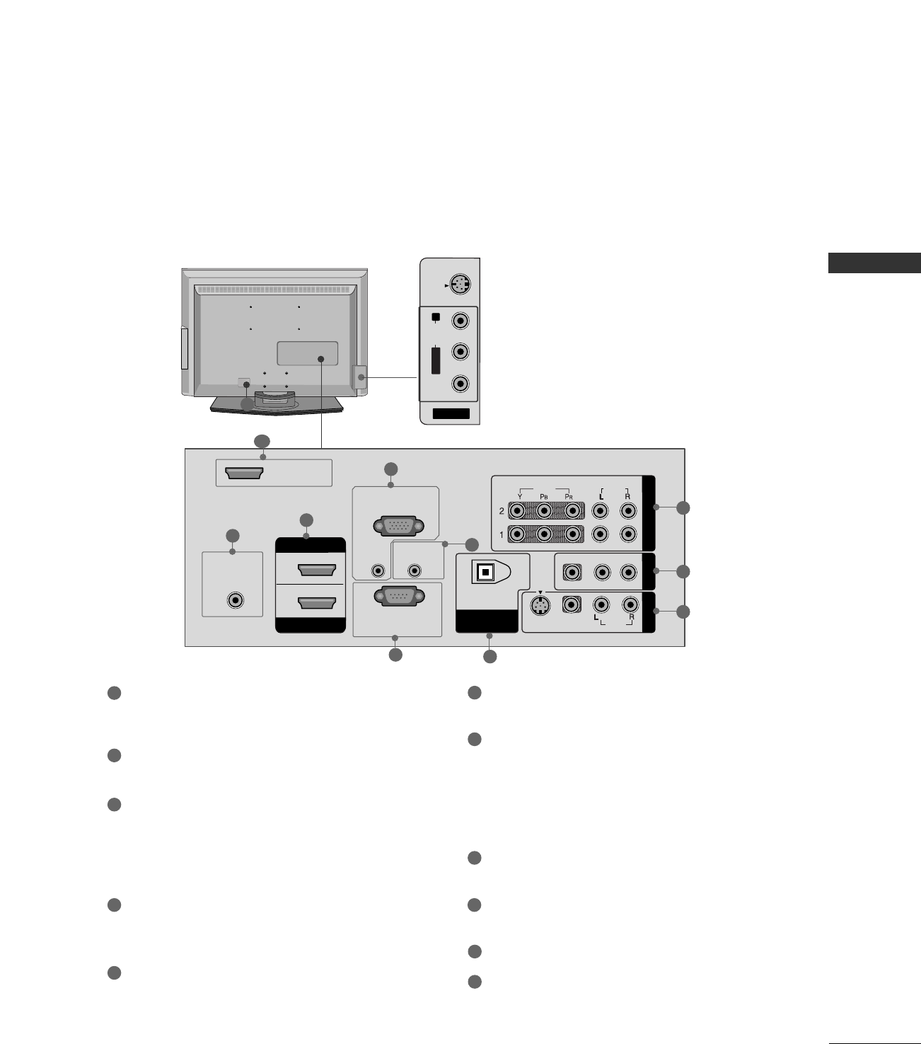
LCD TV Model
COMPONENT IN
Connect a component video/audio device to these
jacks.
AV OUT
Connect a second TV or monitor.
AV (Audio/Video) IN 1
Connect audio/video output from an external
device to these jacks.
S-VIDEO
Connect S-Video out from an S-VIDEO device.
ANTENNA/CABLE IN
Connect over-the air signals to this jack.
Connect cable signals to this jack.
DIGITAL AUDIO OUT
Connect digital audio from various types of equipment.
Note: In standby mode, these ports do not work.
HDMI/DVI IN
Connect a HDMI signal to 1 or 2.
RGB IN (PC)
Connect the monitor output from a PC to the
appropriate input port.
AUDIO IN (RGB/DVI)
Connect the monitor output from a PC to the
appropriate input port.
Remote Control Port
Connect your wired remote control.
RS-232C IN (CONTROL & SERVICE) PORT
Connect to the RS-232C port on a PC.
SERVICE
Power Cord Socket
For operation with AC power.
Caution: Never attempt to operate the TV on DC
power.
1
7
6
8
9
10
11
2
3
4
5
AV IN 2
L/MONO
R
AUDIO
VIDEO
S-VIDEO
( )
S-VIDEO Input
Provides better picture quality than the
video input.
AUDIO Input
Connections are available for listening to
stereo sound from an external device.
VIDEO Input
Connects the video signal from a video
device.
R
HDMI IN
HDMI/DVI IN
VIDEO
AUDIO
VIDEO
AUDIO
MONO
( )
S-VIDEO
ANTENNA/
CABLE IN
REMOTE
CONTROL IN
RS-232C IN
(CONTROL & SERVICE)
RGB IN
(PC)
AUDIO IN
(RGB/DVI)
DIGITAL AUDIO
OUT
OPTICAL
1
2
SERVICE
COMPONENT IN AV OUT
AV IN 1
2
1
8
3
7
6
95
10
4
11
PREPARATION
10
ATTACHING THE TV TO A WALL
PREPARTION
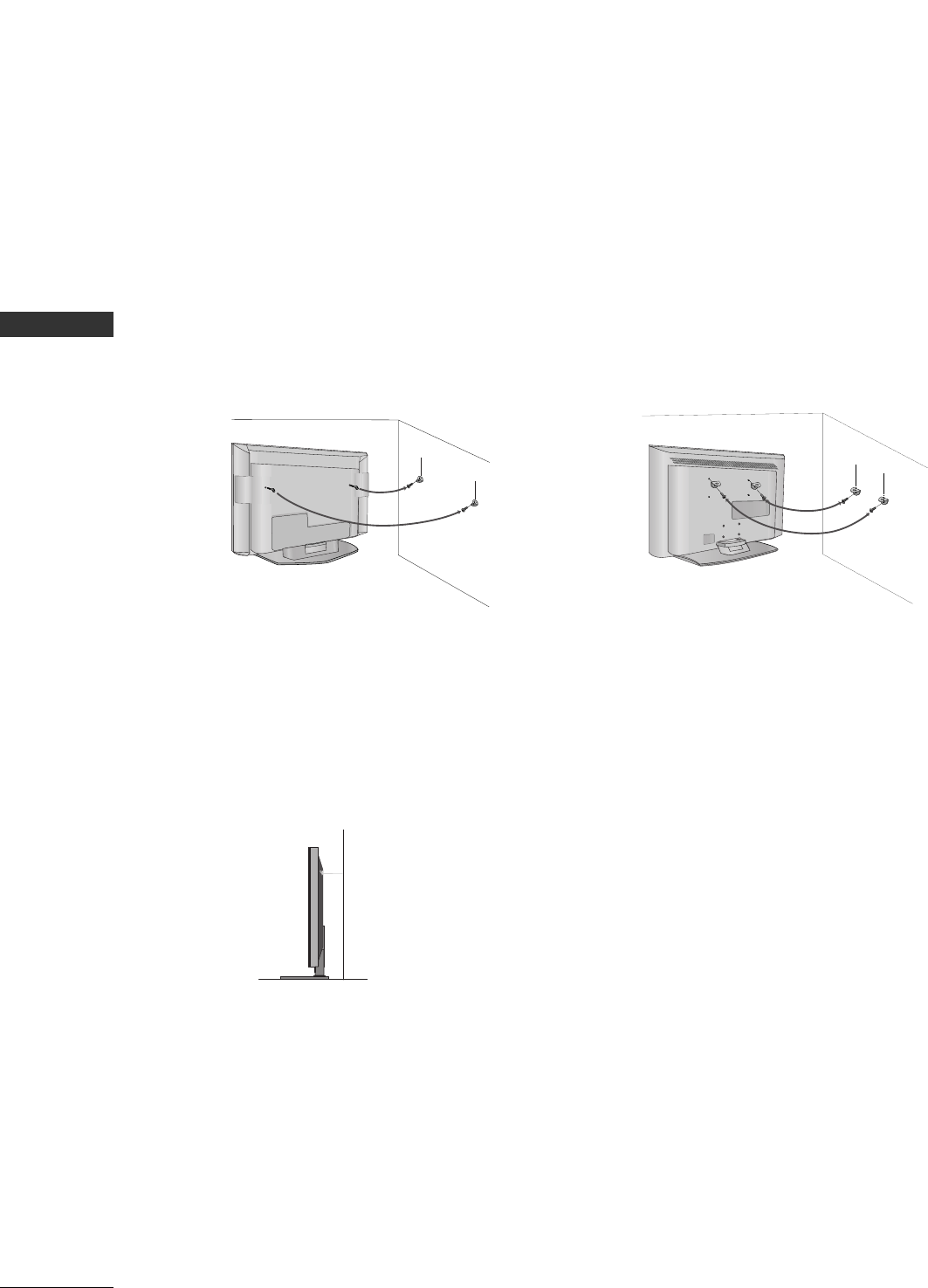
We recommend that you set up the TV close to a wall so it cannot fall over if pushed backwards.
Additionally, we recommend that the TV be attached to a wall so it cannot be pulled in a forward direction,
potentially causing injury or damaging the product.
Caution: Please make sure that children don’t climb on or hang from the TV.
Plasma TV Model LCD TV Model
■Insert the eye-bolts (or TV brackets and bolts) to tighten the product to the wall as shown in the picture.
*If your product has the bolts in the eye-bolts position before inserting the eye-bolts, loosen the bolts.
Secure the wall brackets with the bolts (not provided as parts of the product, must purchase separately) on
the wall. Match the height of the bracket that is mounted on the wall to the holes in the product.
Ensure the eye-bolts or brackets are tightened securely.
■Use a sturdy rope (not provided as parts of the product, must pur-
chase separately) to tie the product. It is safer to tie the rope so it
becomes horizontal between the wall and the product.
PREPARATION
11
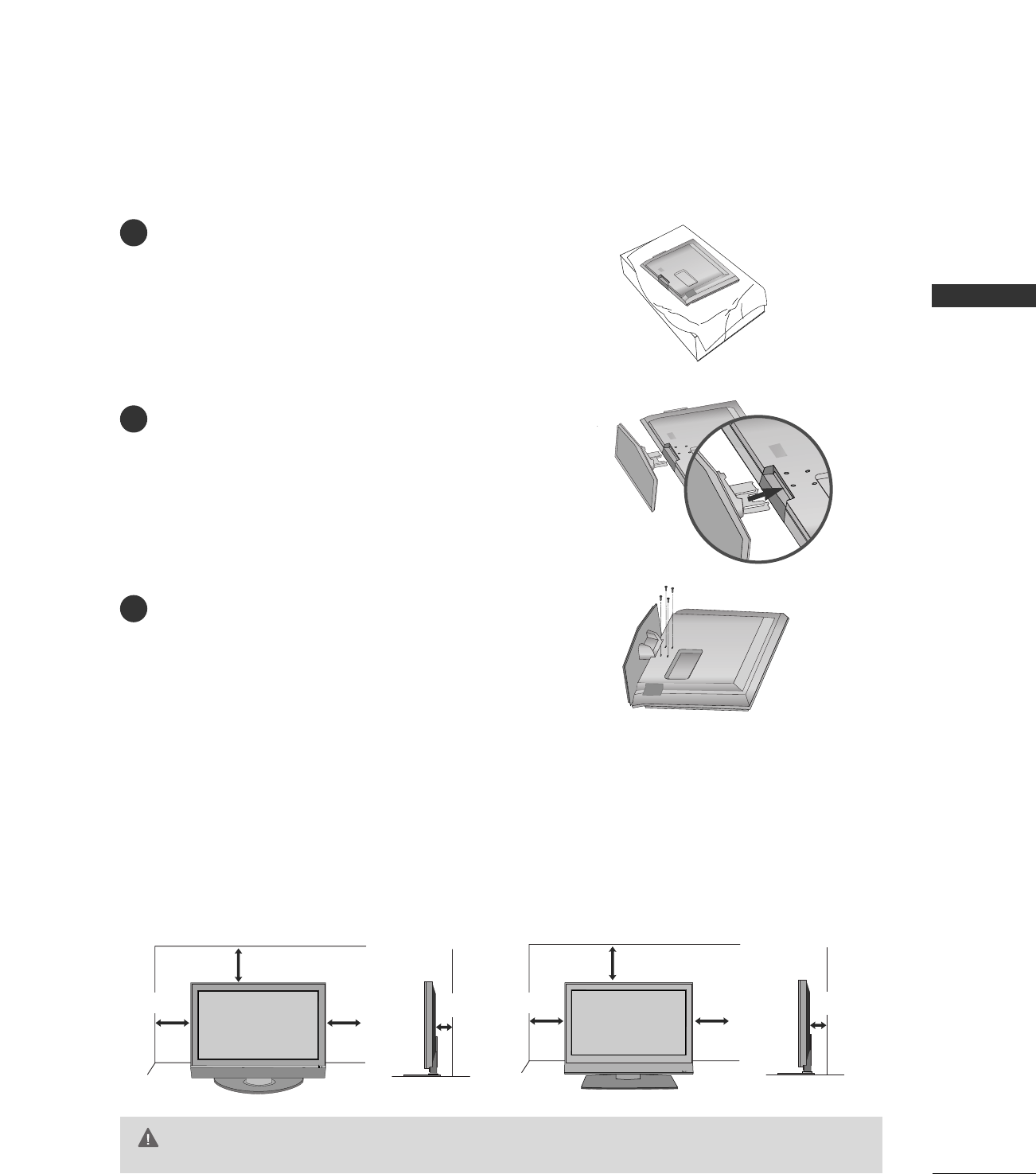
STAND INSTALLATION (Only 32 inch LCD TV models)
Carefully place the product screen side down on
a cushioned surface that will protect product and
screen from damage.
Assemble the product stand with the product as
shown.
Install the 4 bolts securely, in the back of the
product in the holes provided.
1
2
3
For proper ventilation, allow a clearance of 4inches on each side from the wall.
4 inches
4 inches
4 inches 4 inches
R
4 inches
4 inches
4 inches 4 inches
Ensure adequate ventilation by following the clearance recommendations.
CAUTION
Plasma TV LCD TV
DESKTOP PEDESTAL INSTALLATION
PREPARATION
12
BACK COVER FOR WIRE ARRANGEMENT
PREPARTION
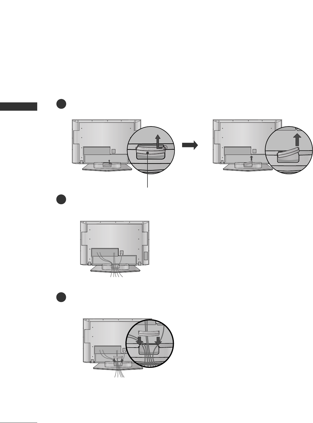
Plasma TV
Hold the CABLE MANAGEMENT with both hands and pull it backward as shown.
Connect the cables as necessary.
To connect an additional equipment, see the External equipment Connections section.
1
2
Install the CABLE MANAGEMENT as shown.
3
CABLE MANAGEMENT
PREPARATION
13
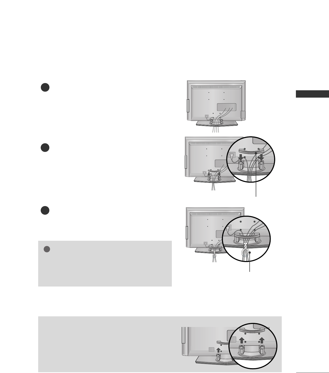
LCD TV
Connect the cables as necessary.
To connect an additional equipment, see the External
equipment Connections section.
Install the CABLE MANAGEMENT as shown.
How to remove the CABLE MANAGEMENT
GGHold the CABLE MANAGEMENT with both hands and
pull it backward.
CABLE MANAGEMENT
TWISTER HOLDER
GGDo not hold the CABLE MANAGEMENT when moving
the product.
- If the product is dropped, you may be injured or the
product may be broken.
NOTE
!
1
2
Bundle the cables using the supplied twister holder.
3
PREPARATION
14
PREPARTION
■To prevent the equipment damage, never plug in any power cords until
you have finished connecting all equipment.
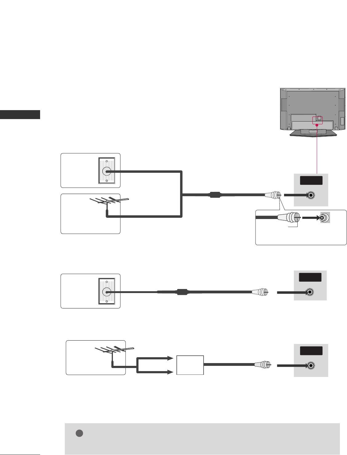
1. Antenna (Analog or Digital)
Wall Antenna Socket or Outdoor Antenna without a Cable Box Connections.
For optimum picture quality, adjust antenna direction if needed.
2. Cable
R
( )
Wall
Antenna
Socket
Outdoor
Antenna
(VHF, UHF)
Cable TV
Wall Jack
Multi-family Dwellings/Apartments
(Connect to wall antenna socket)
RF Coaxial Wire (75 ohm)
RF Coaxial Wire (75 ohm)
Single-family Dwellings /Houses
(Connect to wall jack for outdoor antenna) Be careful not to bend the bronze
wire when connecting the antenna.
Bronze Wire
R
( )
ANTENNA/
CABLE IN
R
( )
ANTENNA/
CABLE IN
R
( )
ANTENNA/
CABLE IN
GGThe TV will let you know when the analog, cable, and digital channel scans are complete.
NOTE
!
■To improve the picture quality in a poor signal area, please purchase a signal amplifier and install properly.
■If the antenna needs to be split for two TV’s, install a 2-Way Signal Splitter.
■If the antenna is not installed properly, contact your dealer for assistance.
Antenna
UHF
Signal
Amplifier
VHF
EXTERNAL EQUIPMENT SETUP
15
HD RECEIVER SETUP
EXTERNAL EQUIPMENT SETUP
This TV can receive Digital Over-the-air/Cable signals without an external digital set-top box. However, if you
do receive digital signals from a digital set-top box or other digital external device, refer to the figure as shown
below.
DIGITAL AUDIO
OUT
OPTICAL
AV OUT
AV IN 1
VIDEO
AUDIO
MONO
( )
S-VIDEO
COMPONENT IN
VIDEO
AUDIO
Y L RPBPR
When connecting Component cable
1 2
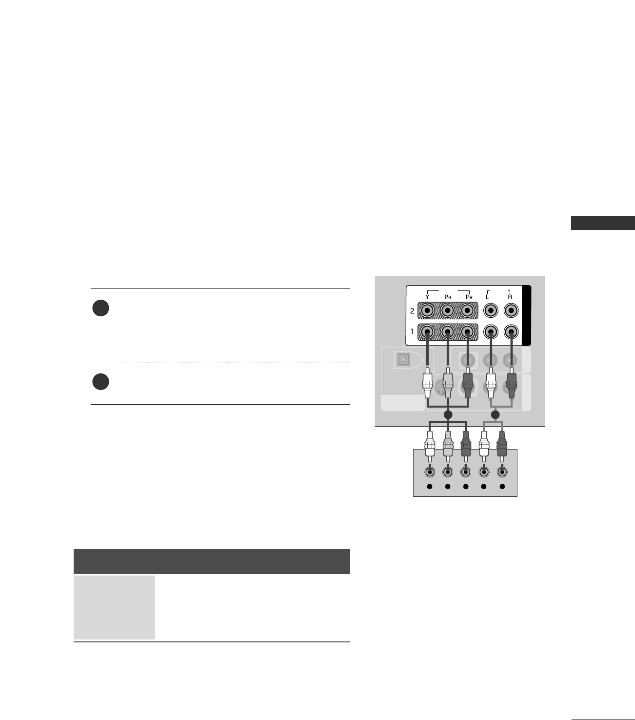
1. How to connect
Connect the video outputs (Y, PB, PR)of the digital set
top box to the CCOOMMPPOONNEENNTT IINN VVIIDDEEOO 11jacks on
the set. Match the jack colors
(Y = green, PB= blue, and PR= red).
Connect the audio output of the digital set-top box to
the CCOOMMPPOONNEENNTT IINN AAUUDDIIOO 11jacks on the set.
2
1
2. How to use
■Turn on the digital set-top box.
(Refer to the owner’s manual for the digital set-top box.)
■Select CCoommppoonneenntt 11 input source with using the
IINNPPUUTT button on the remote control.
■If connected to CCOOMMPPOONNEENNTT IINN22 input, select
CCoommppoonneenntt 22 input source.
Signal
480i
480p
720p
108 0 i
Component 1/2
Yes
Yes
Yes
Yes
HDMI1/DVI,
HDMI2
No
Yes
Yes
Yes
EXTERNAL EQUIPMENT SETUP
16
EXTERNAL EQUIPMENT SETUP
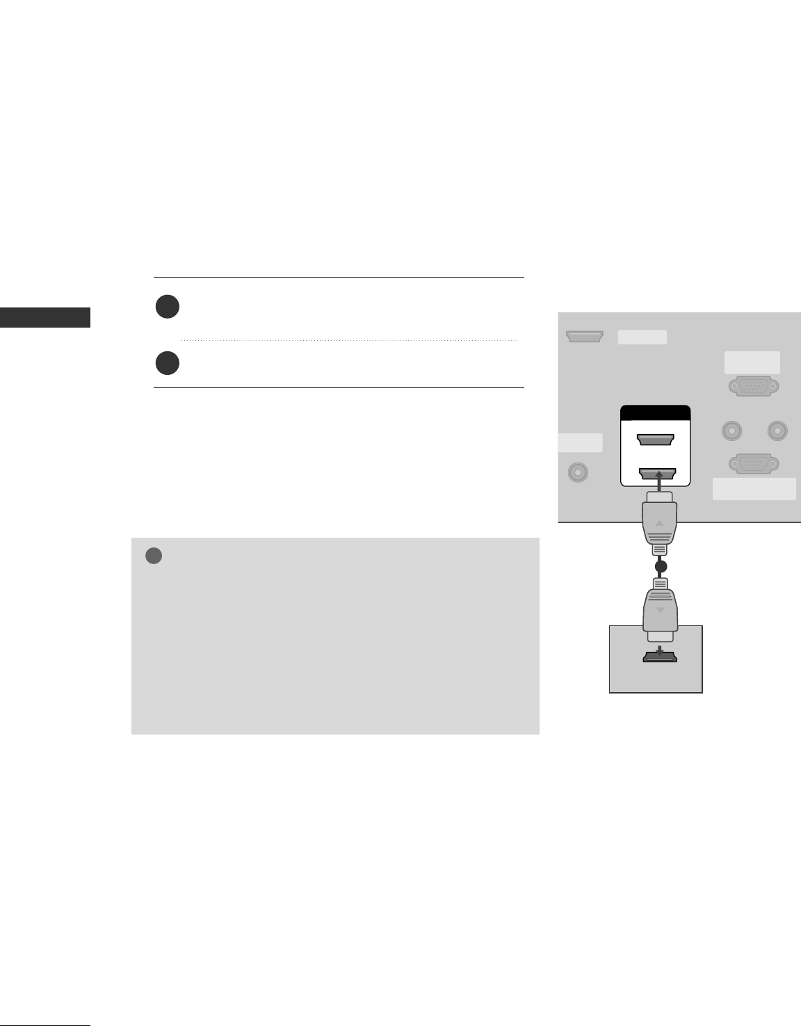
When connecting HDMI cable
Connect the digital set-top box to HHDDMMII//DDVVII IINN 11
or 22 jack on the set.
No separated audio connection is necessary.
1. How to connect
2. How to use
■Turn on the digital set-top box.
(Refer to the owner’s manual for the digital set-top box.)
■Select HHDDMMII11//DDVVIIor HHDDMMII22 input source with using
the IINNPPUUTTbutton on the remote control.
2
1
HDMI/DVI IN
ANTENNA/
CABLE IN
REMOTE
CONTROL IN
RS-232C IN
(CONTROL & SERVICE)
RGB IN
(PC)
AUDIO IN
(RGB/DVI)
1
2
SERVICE
HDMI-DTV OUTPUT
1
GGIf the digital set-top box supports Auto HDMI function, the
output resolution of the source device will be automatically
set to 1280x720p.
GGIf the digital set-top box player does not support Auto HDMI,
you need to set the output resolution appropriately.
To get the best picture quality, adjust the output resolution of
the source device to 1280x720p.
NOTE
!
EXTERNAL EQUIPMENT SETUP
17
HDMI/DVI IN
ANTENNA/
CABLE IN
REMOTE
CONTROL IN
RS-232C IN
(CONTROL & SERVICE)
RGB IN
(PC)
AUDIO IN
(RGB/DVI)
DIGITAL AUDIO
OUT
OPTICAL
1
2
SERVICE
COMPONENT IN AV OUT
AV IN 1
VIDEO
AUDIO
MONO
( )
S-VIDEO
VIDEO
AUDIO
L R
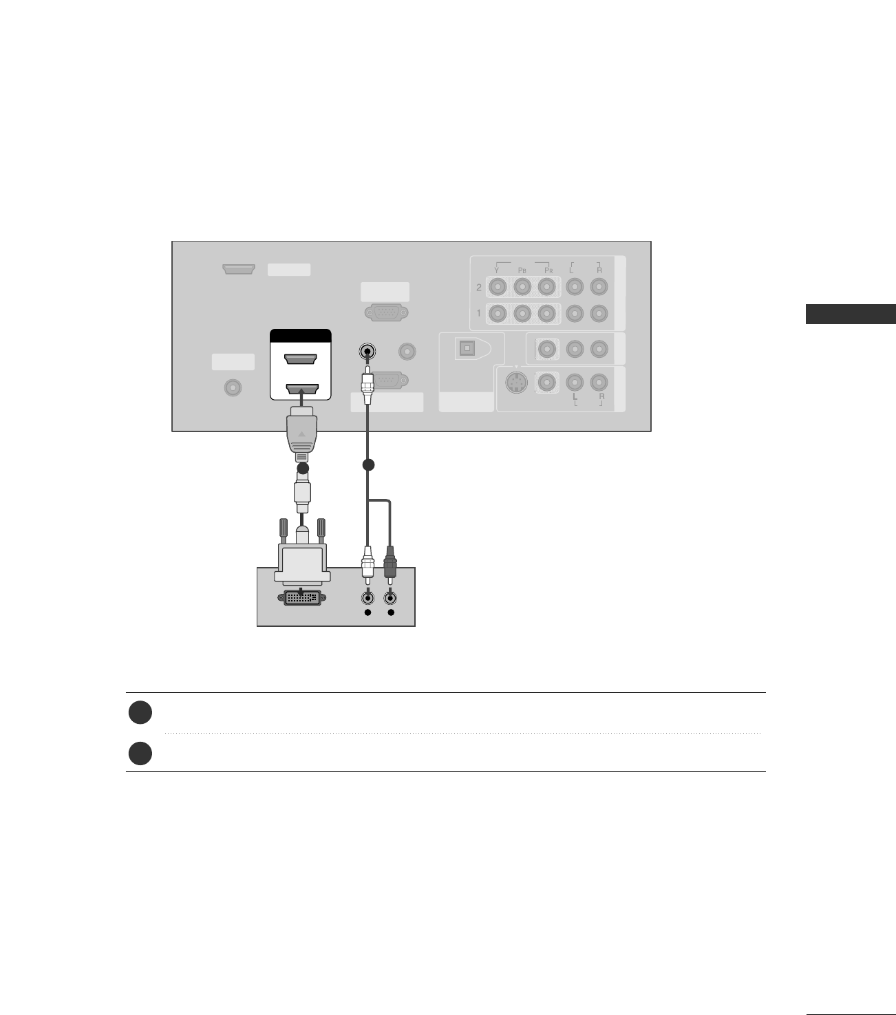
DVI-DTV OUTPUT
Connect the DVI output of the digital set-top box to the HHDDMMII//DDVVII IINN 11or 22 jack on the set.
Connect the audio output of the digital set-top box to the AAUUDDIIOO IINN ((RRGGBB//DDVVII))jack on the set.
1. How to connect
■Turn on the digital set-top box. (Refer to the owner’s manual for the digital set-top box.)
■Select HHDDMMII11//DDVVIIor HHDDMMII22input source with using the IINNPPUUTTbutton on the remote control.
2. How to use
2
1
12
When connecting HDMI to DVI cable
EXTERNAL EQUIPMENT SETUP
18
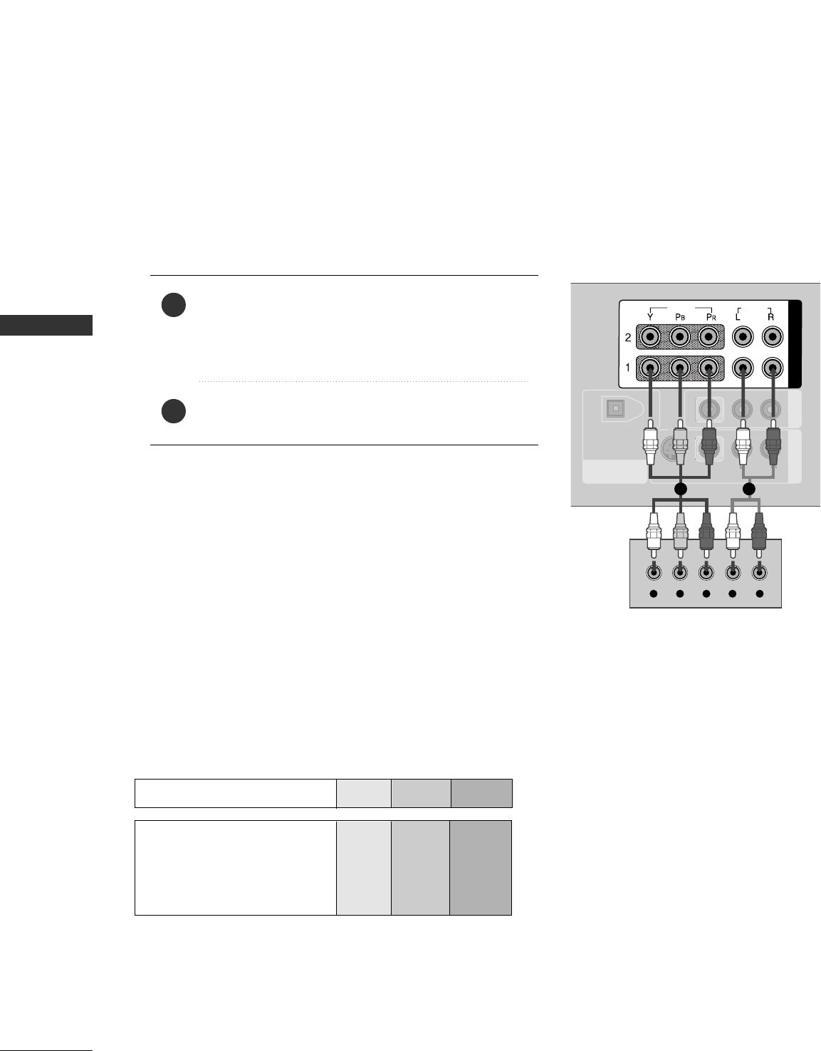
DVD SETUP
EXTERNAL EQUIPMENT SETUP
When connecting Component cable
DIGITAL AUDIO
OUT
OPTICAL
AV OUT
AV IN 1
VIDEO
AUDIO
MONO
( )
S-VIDEO
COMPONENT IN
VIDEO
AUDIO
Y L RPBPR
AUDIO
( )
Component Input ports
To get better picture quality, connect a DVD player to the component input ports as shown below.
Component ports on the TV
YPBPR
Video output ports
on DVD player
Y
Y
Y
Y
PB
B-Y
Cb
Pb
PR
R-Y
Cr
Pr
Connect the video outputs (Y, PB, PR)of the DVD to
the CCOOMMPPOONNEENNTT IINN VVIIDDEEOO11jacks on the set.
Match the jack colors
(Y = green, PB= blue, and PR= red).
Connect the audio outputs of the DVD to the
CCOOMMPPOONNEENNTT IINN AAUUDDIIOO11jacks on the set.
1. How to connect
2. How to use
■Turn on the DVD player, insert a DVD.
■Select CCoommppoonneenntt 11 input source with using the IINNPPUUTT
button on the remote control.
■If connected to CCOOMMPPOONNEENNTT IINN 22 input, select
CCoommppoonneenntt 22 input source.
■Refer to the DVD player's manual for operating instructions.
2
1
1 2

EXTERNAL EQUIPMENT SETUP
19
When connecting with an S-Video cable
DIGITAL AUDIO
OUT
OPTICAL
COMPONENT IN AV OUT
AV IN 1
VIDEO
S-VIDEO
VIDEO
AUDIO
AUDIOUDIO
MONO
( )
L R
S-VIDEO
AUDIO
12
HDMI/DVI IN
NTENNA/
CABLE IN
REMOTE
CONTROL IN
RS-232C IN
(CONTROL & SERVICE)
RGB IN
(PC)
AUDIO IN
(RGB/DVI)
1
2
SERVICE
HDMI-DVD OUTPUT
AUDIO
( )
1
Connect the S-VIDEO output of the DVD to the
SS--VVIIDDEEOOinput on the set.
Connect the audio outputs of the DVD to the AAUUDDIIOO
input jacks on the set.
1. How to connect
2. How to use
■Turn on the DVD player, insert a DVD.
■Select AAVV11input source with using the IINNPPUUTTbutton on
the remote control.
■If connected to AAVV IINN22, select AAVV22 input source.
■Refer to the DVD player's manual for operating instructions.
When connecting HDMI cable
Connect the HDMI output of the DVD to the
HHDDMMII//DDVVII IINN 11or 22jack on the set.
No separated audio connection is necessary.
1. How to connect
2. How to use
■Select HHDDMMII11//DDVVIIor HHDDMMII22input source with using
the IINNPPUUTTbutton on the remote control.
■Refer to the DVD player's manual for operating instructions.
2
1
2
1
GGIf the DVD supports Auto HDMI function, the DVD output
resolution will be automatically set to 1280x720p.
GGIf the DVD does not support Auto HDMI, you need to set
the output resolution appropriately.
To get the best picture quality, adjust the output resolution
of the DVD to 1280x720p.
NOTE
!